a mutation-based framework for automated testing of timelinessoffutt/documents/theses/nilsson... ·...
TRANSCRIPT

A Mutation-based Framework for Automated Testing of Timeliness
Robert Nilsson
October 18, 2006
Linkoping Studies in Scienceand Technology
Dissertation No. 10030
Department of Computer and Information ScienceLinkoping University, SE-581 83 Linkoping, Sweden
Linkoping 2006

ISBN 91-85523-35-6 ISSN 0345-7524 © Robert Nilsson, 2006. All rights reserved. Printed in Sweden by LiU-Tryck. Linköping 2006.
i
AbstractA problem when testing timeliness of event-triggered real-time systems is that
response times depend on the execution order of concurrent tasks. Conventionaltesting methods ignore task interleaving and timing and thus do not help determinewhich execution orders need to be exercised to gain confidence in temporal correct-ness. This thesis presents and evaluates a framework for testing of timeliness that isbased on mutation testing theory. The framework includes two complementary ap-proaches for mutation-based test case generation, testing criteria for timeliness, andtools for automating the test case generation process. A scheme for automated testcase execution is also defined. The testing framework assumes that a structured no-tation is used to model the real-time applications and their execution environment.This real-time system model is subsequently mutated by operators that mimic po-tential errors that may lead to timeliness failures. Each mutated model is automat-ically analyzed to generate test cases that target execution orders that are likely tolead to timeliness failures. The validation of the theory and methods in the pro-posed testing framework is done iteratively through case-studies, experiments andproof-of-concept implementations. This research indicates that an adapted form ofmutation-based testing can be used for effective and automated testing of timelinessand, thus, for increasing the confidence level in real-time systems that are designedaccording to the event-triggered paradigm.
Keywords: Automated Testing, Real-time systems, Time constraints, Timeli-ness, Model-based.

ii
Acknowledgements
First and foremost, I would like to thank my supervisors. Sten F. Andler for encour-agement, insightful comments on my work and for being a great boss. Jeff Offutt,for widening my horizon and giving me invaluable guidance in research and the artof writing papers. Jonas Mellin for some interesting discussions and for sharing hisexperiences of thesis writing. I would also like to thank Simin Nadjm-Tehrani forher comments on my work and for always being supportive and welcoming.
Next, I would like to thank the following (present and past) members of theDRTS research group (in alphabetical order), Alexander Karlsson, Ammi Erics-son, Bengt Eftring, Birgitta Lindstrom, Gunnar Mathiason, Henrik Grimm, JorgenHansson, Marcus Brohede, Mats Grindal, Ragnar Birgisson and Sanny Gustavsson.It has been a pleasure working with all of you and I’m grateful for all the procrasti-nation and tilted discussions that we have shared. In particular, I would like to thankAlexander Karlsson for helping me with the attempts to seed timeliness errors.
I am also very grateful for all the contacts and opportunities given to me throughthe ARTES network and FlexCon project. It is probably not a coincidence that re-search in this thesis is inspired by ideas originating from Uppsala, Vasteras andLund. In particular, I want to thank Paul Pettersson, Hans Hansson, Anita Andlerand Roland Gronros, for being good research catalysts and for organizing interest-ing summer schools and conferences. In the FlexCon project, I would specificallylike to thank Karl-ErikArzen and Klas Nilsson for valuable input and feedback.I also want to thank Dan Henriksson for introducing me to the intricacies of thetruetime tool and for helping with the controller design of the experiments in ourjoint paper. In this context, I would also like to thank Anders Pettersson and HenrikThane for interesting discussions about subtle issues of real-time system testing.
I want to thank the fellow employees at the former department of ComputerScience and the School of Humanities and Informatics at the University of Skovde.I believe that there is great potential in a small academy being so dedicated toresearch. Keep up the good work!
Finally, I want to thank my family; Anders, Jane and Johan Nilsson and mygrandmother Ulla Hjalmarsson for coping with me during my exile in academia. Avery special thanks goes to my girlfriend Viola Bergman, for her cheerful supportand warm encouragements. At last, I want to thank and tribute my grandfather,Helge Hjalmarsson, for being a great inspiration for me.

iii
List of Publications
Some of the contributions of this Ph.D thesis has previously been published in thefollowing papers and technical reports.
• R. Nilsson, S.F. Andler, and J.Mellin. Towards a Framework for AutomatedTesting of Transaction-Based Real-Time Systems. InProceedings of EigthInternational Conference on Real-Time Computing Systems and Applica-tions (RTCSA2002), pages 109–113, Tokyo, Japan, March 2002.
• R. Nilsson. Thesis proposal : Automated timeliness testing of dynamic real-time systems. Technical Report HS-IDA-TR-03-006, School of Humanitiesand Informatics, Univeristiy of Skovde, 2003.
• R. Nilsson, J. Offutt, and S. F. Andler. Mutation-based testing criteria fortimeliness. InProceedings of the 28th Annual Computer Software and Ap-plications Conference (COMPSAC), pages 306–312, Hong Kong, September2004. IEEE Computer Society.
• R. Nilsson and D. Henriksson. Test case generation for flexible real-timecontrol systems. InProceedings of the 10th IEEE International Conferenceon Emerging Technologies and Factory Automation, pages 723–721, Catania,Italy, September 2005.
• R. NilssonJ. Offutt and J. Mellin, Test case generation for Mutation-basedtesting of timeliness, InProceedings of the 2nd International Workshop onModel-Based Testing, pages 102-121, Vienna, Austria, March 2006.

iv
Contents
1 Introduction 11.1 Overview . . . . . . . . . . . . . . . . . . . . . . . . . . . . . . 11.2 Results and Contributions . . . . . . . . . . . . . . . . . . . . . . 21.3 Thesis Outline . . . . . . . . . . . . . . . . . . . . . . . . . . . . 3
I Timeliness Demise 5
2 Dynamic Real-Time Systems 72.1 Real-time System Preliminaries . . . . . . . . . . . . . . . . . . 72.2 Tasks and Resources . . . . . . . . . . . . . . . . . . . . . . . . 82.3 Design and Scheduling . . . . . . . . . . . . . . . . . . . . . . . 10
3 Testing Real-time Systems 133.1 Software Testing Preliminaries . . . . . . . . . . . . . . . . . . . 133.2 Testing Criteria . . . . . . . . . . . . . . . . . . . . . . . . . . . 153.3 Issues when Testing Real-Time Systems . . . . . . . . . . . . . . 163.4 Testing of Timeliness . . . . . . . . . . . . . . . . . . . . . . . . 173.5 Timeliness Faults, Errors and Failures . . . . . . . . . . . . . . . 18
4 Problem Definition: Testing Dynamic Real-Time Systems 214.1 Purpose . . . . . . . . . . . . . . . . . . . . . . . . . . . . . . . 214.2 Motivation for Automated Testing of Timeliness . . . . . . . . . . 214.3 Problem Definition . . . . . . . . . . . . . . . . . . . . . . . . . 224.4 Approach and Delimitations . . . . . . . . . . . . . . . . . . . . 24
4.4.1 Thesis Statement . . . . . . . . . . . . . . . . . . . . . . 244.4.2 Objectives . . . . . . . . . . . . . . . . . . . . . . . . . 25
v
vi Contents
II Rise of the Mutated Models 27
5 A Framework for Testing Dynamic Real-Time Systems 295.1 Framework Overview . . . . . . . . . . . . . . . . . . . . . . . 295.2 Timeliness Test Cases . . . . . . . . . . . . . . . . . . . . . . . 315.3 Mutation-based Test Case Generation . . . . . . . . . . . . . . . 325.4 Test Execution . . . . . . . . . . . . . . . . . . . . . . . . . . . . 34
6 Mutation-based Testing Criteria for Timeliness 376.1 Motivation . . . . . . . . . . . . . . . . . . . . . . . . . . . . . . 376.2 Adopted Modelling Formalism . . . . . . . . . . . . . . . . . . . 386.3 Mutation Operators . . . . . . . . . . . . . . . . . . . . . . . . . 41
6.3.1 Task Set Mutation Operators . . . . . . . . . . . . . . . . 426.3.2 Automata Mutation Operators . . . . . . . . . . . . . . . 45
6.4 Mutation-based Testing Criteria . . . . . . . . . . . . . . . . . . 466.5 Generation of Test Cases Using Model-Checking . . . . . . . . . 486.6 Validation of Mutation Operators . . . . . . . . . . . . . . . . . 49
7 Generation of Test Cases Using Heuristic-driven Simulations 537.1 Motivation . . . . . . . . . . . . . . . . . . . . . . . . . . . . . 537.2 Genetic Algorithms for Test case Generation . . . . . . . . . . . 54
7.2.1 Genome Mapping Function . . . . . . . . . . . . . . . . 567.2.2 Fitness Function . . . . . . . . . . . . . . . . . . . . . . 577.2.3 Heuristic Cross-over Functions . . . . . . . . . . . . . . . 57
7.3 Testing of Time Dependent Control Performance . . . . . . . . . 597.4 Test Case Generation Experiments . . . . . . . . . . . . . . . . . 61
7.4.1 Base-line Real-time System . . . . . . . . . . . . . . . . 627.4.2 Complex Dynamic Real-time System . . . . . . . . . . . 647.4.3 Mixed Load Real-time Control System . . . . . . . . . . 66
III Empiricism strikes back 71
8 T 3: A Tool for Mutation-based Testing of Timeliness 738.1 Overview . . . . . . . . . . . . . . . . . . . . . . . . . . . . . . 738.2 Flextime Simulator Extensions . . . . . . . . . . . . . . . . . . . 74
8.2.1 TrueTime . . . . . . . . . . . . . . . . . . . . . . . . . . 758.2.2 Task Sets and Execution Patterns . . . . . . . . . . . . . . 758.2.3 Activation Patterns . . . . . . . . . . . . . . . . . . . . . 78

Contents vii
8.3 Test Case Generation Support . . . . . . . . . . . . . . . . . . . 788.3.1 Modes for Generating Test Cases . . . . . . . . . . . . . 788.3.2 Support for Task Instance Modelling . . . . . . . . . . . . 81
9 Case Study: Testing using the Mutation-based Framework 839.1 Overview . . . . . . . . . . . . . . . . . . . . . . . . . . . . . . 839.2 A Flexcon Demonstrator Prototype . . . . . . . . . . . . . . . . 84
9.2.1 Real-time Design . . . . . . . . . . . . . . . . . . . . . 849.2.2 Target Platform . . . . . . . . . . . . . . . . . . . . . . 879.2.3 Test Harness . . . . . . . . . . . . . . . . . . . . . . . . 899.2.4 Task Implementation . . . . . . . . . . . . . . . . . . . . 93
9.3 Applying the Framework for Testing of Timeliness . . . . . . . . 939.3.1 Constructing Task Input Data . . . . . . . . . . . . . . . 949.3.2 Combining Task Input Data for System Level Testing . . . 95
9.4 Demonstrator Testing Experiments . . . . . . . . . . . . . . . . . 979.4.1 Experiment 1 - Framework Testing Effectiveness . . . . . 989.4.2 Experiment 2 - Effectiveness with Seeded Errors . . . . . 104
10 Discussion 10910.1 Mutation Operators and Testing Criteria . . . . . . . . . . . . . . 109
10.1.1 System Specific Mutation Operators . . . . . . . . . . . 11110.1.2 Guidelines for Adding Mutation Operators . . . . . . . . 112
10.2 Test Case Generation Issues . . . . . . . . . . . . . . . . . . . . 11510.2.1 Scalability of Test Case Generation . . . . . . . . . . . . 11610.2.2 Genetic Algorithm Enhancements . . . . . . . . . . . . . 116
10.3 Prefix-based Test Case Execution . . . . . . . . . . . . . . . . . 11710.3.1 Prefixed Test Cases for Testing of Timeliness . . . . . . . 11910.3.2 A Prefix-based Test Case Execution Scheme . . . . . . . 120
10.4 Validation of Mutation-based Testing of Timeliness . . . . . . . . 12110.4.1 Evaluating Timeliness Test Cases . . . . . . . . . . . . . 12110.4.2 Validation of Thesis Statement . . . . . . . . . . . . . . . 122
11 Related Work 12511.1 Test Case Generation . . . . . . . . . . . . . . . . . . . . . . . . 12511.2 Testing of Real-Time Systems . . . . . . . . . . . . . . . . . . . 129
viii Contents
12 Conclusions 13112.1 Summary . . . . . . . . . . . . . . . . . . . . . . . . . . . . . . 13112.2 Contributions . . . . . . . . . . . . . . . . . . . . . . . . . . . . 13212.3 Future Work . . . . . . . . . . . . . . . . . . . . . . . . . . . . 133
References 137
A Demonstrator Task Code 145
B Demonstrator Tasks Testing 155
C Case-Study Test Execution Results 163
D Mutation Operators Overview 167
Chapter 1
Introduction
The introduction chapter provides an overview of the contents covered by this the-sis. The scientific problem and solution approach are briefly introduced and moti-vated in section 1.1. The results and contributions are summarized in section 1.2.Finally, section 1.3 presents the structure of the reminder of the thesis.
1.1 Overview
Real-time systems must be dependable as they often operate in tight interactionwith human operators and valuable equipment. A trend is to increase the flexibilityof such systems so that they can support more features while running on “off-the-shelf” hardware platforms. However, with the flexibility comes increased softwarecomplexity and non-deterministic temporal behavior. There is a need for verifica-tion methods to detect errors arising from temporal faults so that confidence canstill be placed in the safety and reliability of such systems.
A problem associated with the testing of real-time applications is that theirtimeliness depends on the execution order of tasks. This is particularly problematicfor event-triggered and dynamically scheduled real-time systems, in which eventsmay influence the execution order at any time (Schutz 1994). Furthermore, tasksin real-time systems behave differently from one execution to the next, dependingnot only on the implementation of real-time kernels and program logic, but also onefficiency of acceleration hardware such as caches and branch-predicting pipelines.Non-deterministic temporal behavior necessitates methods and tools for effectively
1

2 Introduction
detecting the situations when errors in temporal estimations can cause the failureof dependable applications.
The timeliness of embedded real-time systems is traditionally analyzed andmaintained using scheduling analysis techniques or regulated online through ad-mission control and contingency schemes (Burns & Wellings 2001). These tech-niques use assumptions about the tasks and load patterns that must be correct fortimeliness to be maintained. Doing schedulability analysis of non-trivial systemmodels is complicated and requires specific rules to be followed by the run-timesupport system. In contrast, timeliness testing is general in the sense that it ap-plies to all system architectures and can be used to gain confidence in assumptionsby systematically sampling among the execution orders that can lead to misseddeadlines. Hence, from a real-time perspective, timeliness testing is a necessarycomplement to analysis.
It is difficult to construct effective sequences of test inputs for testing timeli-ness without considering the effect on the current set of active tasks and real-timeprotocols. However, existing testing techniques seldom use such information andthey do not predict which execution orders may lead to timeliness failures (Nilsson,Andler & Mellin 2002).
In summary, problems with testing of timeliness arise from a dynamic environ-ment and the vast number of potential execution orders of event-triggered real-timesystems. Therefore, we need to be able to produce test inputs that exercise a mean-ingful subset of these execution orders. Within the field of software testing, severalmethods have been suggested for model-based test case generation but few of themcapture the behavior that is relevant to generate effective timeliness test cases.
This thesis presents a mutation-based method for testing of timeliness that takesinternal behaviors into consideration. The thesis also describes experiments forevaluating the effectiveness of this method.
1.2 Results and Contributions
The results of this thesis form a framework for automatic testing of timeliness fordynamic real-time systems. In this context, a framework means theory and meth-ods as well as associated tools for performing automated testing of timeliness ina structured way1. As a requirement for applying our proposed framework, theestimated temporal properties and resource requirements of real-time applications
1The reason for providing a framework and not simply a method is that there are several ways toperform the steps in the chain from system modelling to test analysis.
1.3 Thesis Outline 3
must be specified in a model. As opposed to other approaches for model-basedtesting of timeliness, properties of the execution environment are part of the modelwhich is used for generating test cases. This provides the advantage that the ef-fects of, for example scheduling protocols and platform overheads, can be capturedduring automatic test case generation.
A set of basic mutation-based testing criteria for timeliness is defined and vali-dated using model-checking techniques. Two methods for generating test cases thatfulfill timeliness testing criteria are presented. One of the methods, based on model-checking, is suitable for dependable systems where a stringent test case generationmethod is preferred. For more complex target systems, the model-checking basedapproach may be impractical. A complementary method based on heuristic-drivensimulations is presented and evaluated in a series of experiments. The thesis alsopresents a prototype tool that integrates with MATLAB/Simulink and support theheuristic-driven method for test-case generation. This tool allows control specificconstraints and processes to be used as input to mutation-based test case generation.
A scheme for automated test case execution that uses the added informationfrom mutation-based test case generation and has the potential to reduce non-determinism is discussed. This method exploits advantages inherent in transactionbased systems and allows testing to be focused on the critical behaviors indicatedby test cases.
The mutation-based testing criteria and test case generation approaches areevaluated in a series of experiments using model-checking and simulations. Theoverall testing framework is evaluated by testing a simplified robot-arm control ap-plication that runs on the Linux/RTAI platform. This study is an example of howthe testing framework can be applied and demonstrates the effectiveness and limi-tations of the suggested approach.
1.3 Thesis Outline
Chapters 2 and 3 introduce relevant concepts from real-time systems developmentand software testing. Chapter 4 provides a more detailed description of the problemaddressed by the thesis, motivates its importance, and presents our approach foraddressing it.
Chapter 5 presents an overview of a framework for mutation-based testing oftimeliness and defines concepts used in the reminder of the thesis, while the pro-posed methods for test case selection and automated test case generation are in-cluded in Chapters 6 and 7. The validation experiments of the proposed methods

4 Introduction
are also presented in this context.Chapter 8 describes the tool support proposed for the framework, and Chapter 9
contains the result of a case study in which the proposed testing framework is usedfor testing timeliness in a real system. In Chapter 10 the contributions of the thesisare discussed and the advantages and disadvantages of the proposed framework aredescribed. Chapter 11 contains related work, Chapter 12 concludes the thesis andelaborates on future work.

EPISODE I
Timeliness Demise
5

Chapter 2
Dynamic Real-Time Systems
This chapter presents real-time systems terminology as well as the relevant back-ground to understand the contributions of this thesis and the systems and situationsto which the results apply.
2.1 Real-time System Preliminaries
Real-time systemsdenote information processing systems which must respond toexternally generated input stimuli within a finite and specified period (Young 1982).Typically, these kinds of systems are also embedded and operate in the context of alarger engineering system – designed for a dedicated platform and application.
Real-time systems typically interact with other sub-systems and processes inthe physical world. This is called theenvironmentof the real-time system. Forexample, the environment of a real-time system that controls a robot arm includesitems coming down a conveyor belt and messages from other robot control sys-tems along the same production line. Typically, there are explicittime constraints,associated with the response time and temporal behavior of real-time systems.For example, a time constraint for a flight monitoring system can be that oncelanding permission is requested, a response must be provided within 30 seconds(Ramamritham 1995). A time constraint on the response time of a request is calledadeadline. Time constraints come from the dynamic characteristics of the environ-ment (movement, acceleration, etc.) or from design and safety decisions imposedby a system developer.Timelinessrefers to the ability of software to meet time
7
8 Dynamic Real-Time Systems
constraints (c.f. Ramamritham (1995)).Real-time systems are sometimes calledreactivesince they react to changes in
their environment, which is perceived through sensors, and influence it through dif-ferent actuators. Dependable systems are computer systems where people’s lives,environmental or economical value may depend on the continued service of the sys-tem (Laprie 1994). Since real-time systems control hardware that interacts closelywith entities and people in the real world, they often need to be dependable.
2.2 Tasks and Resources
When designing real-time systems, software behavior is often described by a set ofperiodic and sporadic tasks that compete for system resources (for example, proces-sor time, memory and semaphores) (Stankovic, Spuri, Ramamritham & Buttazzo1998). When testing real-time software for timeliness, a similar view of softwarebehavior is useful.
Tasksrefers to pieces of sequential code that are activated each time a specificevent occurs (for example, a timer signal or an external interrupt). While a task maybe implemented by a single thread in a real-time operating system, a thread mightalso implement several different tasks1. For simplicity, we assume a one-to-onemapping between real-time tasks and threads in this thesis. A particular executionof a task is called atask instance.
A real-time applicationis defined by a set of tasks that implements a particularfunctionality for the real-time system. Theexecution environmentof a real-timeapplication is all the other software and hardware needed to make the system be-have as intended, for example, real-time operating systems and I/O devices (Burns& Wellings 2001).
There are basically two types of real-time tasks.Periodictasks are activated at afixed frequency, thus all the points in time when such tasks are activated are knownbeforehand. For example, a task with a period of 4 time units will be activatedat times 0, 4, 8, etc.Aperiodic tasks can be activated at any point in time. Toachieve timeliness in a real-time system, aperiodic tasks must be specified withconstraints on their activation pattern. When such a constraint is present the tasksare calledsporadic. A traditional constraint of this type is aminimum inter-arrivaltimebetween two consecutive task activations. In this thesis we treat all real-timetasks as being either periodic or sporadic, but constraints other than minimum inter-
1Theoretically, a particular task may span over several threads, where each thread can be seen asa resource needed by the task
2.2 Tasks and Resources 9
arrival times may be assumed in some cases. Tasks may also have anoffsetthatdenotes the time before any instance may be activated.
An assumption when analyzing timeliness of real-time systems is that the worst-case execution time (that is, the longest execution time) for each task is known be-forehand. In this context, all the processor instructions which must be executed fora particular task instance contribute to the task execution time. This also includesexecution time of non-blocking operating system calls and library functions usedsynchronously by the task. Furthermore, if tasks have critical sections, the longestexecution time within such sections is assumed to be known. However, for manymodern computer architectures, these figures are difficult to accurately estimate.
The reason for this difficulty is that hardware developers often optimize theperformance of processors to be competitive for general computing. This is doneby using mechanisms that optimize average execution times, such as multiple levelsof caches and branch-predicting pipelines (Petters & Farber 1999). The combinedeffect of several such mechanisms increases system complexity so that the exactexecution times appear non-deterministic with respect to control-flow and inputdata of tasks. Nevertheless, estimates based on measurements and assumptionsare used during the analysis of dependable real-time systems, since no accurateand practical method exists to acquire the exact worst case execution times. Theseestimates may be the sources of timeliness failures.
Theresponse timeof a real-time task is the time it takes from when the task isactivated until it finishes its execution2. The response times of a set of concurrenttasks depend on the order in which they are scheduled to execute. We call this theexecution orderof tasks.
In this thesis, ashared resourceis an entity needed by several tasks but thatshould only be accessed by one task at a time. Examples of such resources includedata structures containing state variables that need to be internally consistent, andnon-reentrant library functions. Mutual exclusion between tasks can be enforcedby holding a semaphore or executing within a monitor.
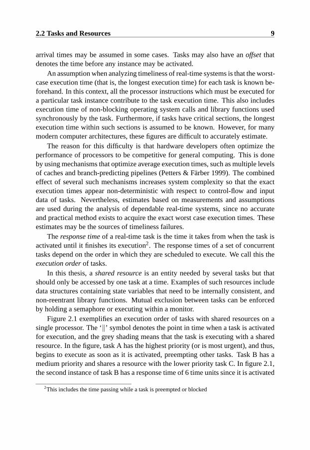
Figure 2.1 exemplifies an execution order of tasks with shared resources on asingle processor. The ‘‖’ symbol denotes the point in time when a task is activatedfor execution, and the grey shading means that the task is executing with a sharedresource. In the figure, task A has the highest priority (or is most urgent), and thus,begins to execute as soon as it is activated, preempting other tasks. Task B has amedium priority and shares a resource with the lower priority task C. In figure 2.1,the second instance of task B has a response time of 6 time units since it is activated
2This includes the time passing while a task is preempted or blocked
10 Dynamic Real-Time Systems
A
B
C
Time0 5 10 15
Figure 2.1: Task execution model
at time 5 and finishes its execution at time 11.Blockingoccurs when a real-time task scheduled for execution needs to use a
shared resource already locked by another task. In figure 2.1 the second instanceof task B is blocked from time 7 to time 9 because it has the highest priority, but itcannot execute since task C has locked a required resource. Incorrect assumptionsabout blocking are sources of timeliness failures.
Tasks may also be associated with criticality levels. One of the most simpleclassifications of criticality is thathard real-time tasks are expected to meet theirtime constraints, whereassoft real-time tasks can occasionally violate time con-straints without causing failures.
2.3 Design and Scheduling
Since there are many different types of real-time systems this section presents clas-sifications of real-time systems and clarifies in what context our problems and re-sults are relevant.
Kopetz et al. describe two ways of designing real-time systems; time-triggeredand event-triggered (Kopetz, Zainlinger, Fohler, Kantz, Puschner & Schutz 1991).The primary difference between them is that time-triggered systems observe theenvironment and perform actions at pre-specified points in time, whereas event-triggered systems detect and act on events immediately.
A pure time-triggeredreal-time computer system operates with a fixed period.At the end of each period the system observes all the events that have occurred sincethe period started and reacts to them by executing the corresponding tasks in thefollowing period. The computations that are made in one period must be finishedbefore the next period starts. Consequently, a time-triggered system design requiresthat information about events occurring in the environment is stored until the nextperiod starts. The scheduling of time-triggered real-time systems is made beforethe system is put into operation to guarantee that all the tasks meet their deadlines,
2.3 Design and Scheduling 11
given the assumed worst-case load. This means that a time-triggered real-timesystem may have to be completely redesigned if new features are added or if theload characteristics change.
In anevent-triggeredreal-time system, the computer reacts to events by imme-diately activating a task that should service the request within a given time. Theexecution order of the active set of tasks is decided by a system scheduling policyand, for example, the resource requirements, criticality or urgency of the tasks.
It is also common to make a distinction between statically scheduled and dy-namically scheduled systems. According to Stankovic et al. (Stankovic et al. 1998),the difference is that in statically scheduled systems all the future activations oftasks are known beforehand, whereas in dynamically scheduled systems, they arenot. Statically scheduledsystems are often scheduled before the system goes intooperation, either by assigning static priorities to a set of periodic tasks or by ex-plicitly constructing a schedule (for example, using a dispatch-table or cyclic ex-ecutive).Dynamically scheduledsystems perform scheduling decisions during op-eration and may change the order of task execution depending on the system state,locked resources, and new task activations. A time-triggered system is by definitionstatically scheduled, whereas an event-triggered system can be scheduled staticallyor dynamically. In this thesis, event-triggered real-time systems that are dynami-cally scheduled are referred to asdynamic real-time systems.
One advantage of dynamic real-time systems is that they do not waste resources“looking” for events in the environment. In particular, if such events seldom occurand require a very short response time (such as an alarm signal or a sudden requestfor an evasive action), a dynamic real-time system would waste less resources thana statically scheduled real-time system. In a statically scheduled system a periodictask would frequently have to “look” for events in the environment to be able todetect them and respond before the deadlines. In this context, resources mean, forexample, processor-time, network bandwidth and electric power.
However, both paradigms have benefits and drawbacks. Statically scheduledsystems offer more determinism and are therefore easier to analyze and test. Onereason for this is that the known activation pattern of periodic tasks repeats aftera certain period of time. This period is called ahyper-periodand is calculatedusing the least common multiplier of all the inter-arrival times of periodic tasks(Stankovic et al. 1998). There are many useful results for analyzing and testingstatically scheduled real-time systems (Schutz 1993, Thane 2000).
This thesis addresses problems associated with the testing of dynamic real-timesystems, because such systems are suitable for many application domains but lackeffective methods for testing of timeliness.

12 Dynamic Real-Time Systems
As an example of a system to which our testing methods can be applied, con-sider an onboard control system for a high-speed train. The system is used in manydifferent types of rail-cars and should operate in changing environments that incor-porate people, therefore it is desirable to use an event-triggered design for someparts of this system. Each car in the train set has a cluster of sensors, actuatorsand dedicated real-time computer nodes for the safety critical control of processes,such as the brakes and the tilt of the cars. These components are interconnectedwith a real-time network. On each rail car there is also a number of event-triggeredreal-time system nodes. The dynamic real-time system is used for monitoring andadjusting the operation of the underlying safety critical real-time control system,performing data-collection for maintenance, and for communicating with nodes inother rail cars and in the engine cockpit. The event-triggered nodes may also runother real-time applications such as controllers for air conditioners, staircases, andcabin doors. These kinds of applications need to be timely, but they are not criticalfor the safety of the passengers of the train.

Chapter 3
Testing Real-time Systems
This chapter presents a relevant background to software testing, in particular con-cepts relating to automated and model-based testing. Furthermore, issues related totesting real-time systems are included.
3.1 Software Testing Preliminaries
Software testingmeans exercising a software system with valued inputs (Laprie1994). In this thesis, the tested software system is called thetarget system. A largefraction1 of the development cost of software is typically spent on testing. Testingis important for development of dependable and real-time software, due to strin-gent reliability requirements and to avoid high maintenance costs. Two purposesof testing are conformance testing and fault-finding testing (Laprie 1994).Con-formance testingis performed to verify that an implementation corresponds to itsspecification whilefault-finding testingtries to find special classes of implementa-tion or design faults. Common to these purposes is the underlying desire to gainconfidence in the system’s behavior.
However, a fundamental limitation of software testing is that it is generally im-possible to test even a small program exhaustively. The reason is that the numberof program paths grows quickly with the number of nested loops and branch state-
1varying from 30 up to 80 percent in the literature, depending on the type of development projectand what activities are considered testing
13

14 Testing Real-time Systems
ments (Beizer 1990). For concurrent and real-time software, the number of possiblebehaviors are even higher due to the interactions between concurrent tasks. Conse-quently, testing cannot show the absence of faults (to prove system correctness), itcan only show the presence of faults (Dahl, Dijikstra & Hoare 1972).
According to Laprie et al. (Laprie 1994),faults are mistakes manifested insoftware implementations. Examples of faults are the incorrect use of conditionsin if-then-else and the misuse of a binary semaphore in a concurrent program. Anerror is an incorrect internal state resulting from reaching a software fault. If noerror handling is present, an error may lead to an externally observable systemfailure. A failure is a deviation from the system’s expected behavior.
Testing is traditionally performed at different levels during a software devel-opment process (Beizer 1990). This thesis focuses onsystem level testingthat isdone on the implemented system as a whole; this typically requires that all partsof the system are implemented and integrated (Beizer 1990). The reason for this isthat some timeliness faults only can be revealed at the system level (Schutz 1994).Other levels areunit testing, where a module or function with a specified interfaceis tested, andintegration testingwhere the interaction between modules is tested.
A distinction is commonly made between structural and functional testing meth-ods (Laprie 1994). Instructural testing methods, test cases are based on systemdesign, code structure and the systems internal architecture. Infunctional testingmethods, the system under test is considered a black-box with an unknown internalstructure; test cases are created based on the knowledge of system requirementsand high level specification models of the system.
This thesis presents a model-based testing method where both requirements andstructural knowledge are used. In particular, the method is an adapted version ofmutation-based testing.
One advantage of model-based testing is that it allows test cases to be automati-cally generated, hence, moving effort from generating specific test cases to buildinga model. Models can be built before the system is implemented and used as a ref-erence or part of a specification of the system. It is also possible to build the modeldirectly for testing purposes after or concurrently with development. Accordingto, for example, Beizer (1990), errors and ambiguities in the specification may bedetected while building models for testing.
Mutation testing is a method in which a program (DeMillo, Lipton & Sayward1978) or a specification model (Ammann & Black 1999) is copied and mutatedso that each copy contains an artificially created fault of a particular type. Eachmutated copy is called amutant. Test cases are specially generated that can revealthe faults in the copies of the program or model (manually, or using reachability
3.2 Testing Criteria 15
tools). For example, if one occurrence of the operator ‘>’ is mutated into theoperator ‘<’, then a test case must be selected that causes the mutated code to beexecuted and the corresponding failure to be detected. If such a test case is found,then the mutant iskilled.
An underlying hypothesis of these methods is that the test cases generatedshould be able to find not only the mutations, but also many faults that are similar,hence, achieving effective coverage of the tested program or system. If a specifica-tion model is used as a source for mutation-based testing, then the implementationmay actually contain some fault that was added some of the mutant models. It isthus useful that such faults correspond to ones likely to occur.
3.2 Testing Criteria
A desirable property of any testing method is to have an associated metric in whichthe completeness of testing can be expressed. It is not trivial to formulate such ametric, since it typically requires bounding the number of possible tests. To achievethis, different test requirements and testing criteria are used.
Test requirementsare specific goals that must be reached or investigated duringtesting (Offutt, Xiong & Liu 1999). For example, a test requirement can be toexecute a specific source code statement, to observe a specific execution order oftasks, or to cover a transition in a state-machine model.
A testing criterion is a way to express some class of testing requirements.Hence, examples of a test criterion can be execute all source code statements con-taining the letter x, execute all possible execution orders of tasks that share data, orcover all transitions in a state machine model.
Once testing criteria have been established, they can be used in two ways. Theycan be used to measuretest coverageof a specific set of test cases, or they can beused during test case generation so that the constructed set of test cases implicitlyfulfills an associated test criterion. A set of test cases that has been generated withthe purpose of fulfilling a specific testing criterion is called atest suitein this thesis.
Test coverage and testing criteria are also used to express the level of ambitionwhen testing software. That is, testing criteria sets a threshold for when an ap-plication has been sufficiently tested, and the test coverage denotes the minimumfraction of test requirements that should be covered.
Testing criteria for mutation testing are typically formulated with respect tothe number of mutated programs or models. That is, the standard testing criterionis “kill all mutants”, but the thoroughness and test effort can be controlled by how
16 Testing Real-time Systems
many different types of mutant are created. For example, a test suite can be requiredto kill all mutants where the variable ‘i’ has been replaced by the variable ‘j’.
When testing concurrent real-time systems, testing criteria for sequential soft-ware can be used on each of the possible execution orders in the system (Thane2000). However, even for a statically scheduled real-time system the number ofexecution orders that need to be tested grows very quickly with the number oftask activations. For dynamic real-time systems, the problem is elevated by thenon-deterministic times between sporadic task activations. Hence, it is necessaryto develop testing criteria for selecting relevant sub-sets of all possible executionorders.
3.3 Issues when Testing Real-Time Systems
Schutz (Schutz 1994) describes issues that need to be considered when testing real-time systems. In particular, some issues impose requirements on the test case gen-eration methods investigated and the experiments conducted in this thesis.
Schutz uses the termobservabilityfor the ability to monitor or log the behaviorof a tested system. Observability is usually achieved by inserting probes that revealinformation about the current state and internal state-changes in the system. Aproblem in this context is that by introducing probes into the real-time softwareyou actually influence the temporal behavior of the system. Hence, you cannotgenerally remove the probes once testing is complete without invalidating the testresults. This problem is usually referred to asprobe-effect(Gait 1986). The mostcommon way to avoid the probe-effect problem is to leave the probes in the system,but direct their output to a channel that consumes the same amount of resources butis inaccessible during operation (Schutz 1993). A special version of this is to have abuilt-in component (software or hardware) that monitors the activity in the systemand then leave that component in the system, or compensate for the activity of sucha component during operation. In systems with scarce computing resources, theprobe-effect makes it desirable to keep the amount of logging to a minimum.
Two related concepts in this context are reproducibility and controllability.Re-producibility refers to the property of the system repeatedly exhibiting identicalbehavior when stimulated with the same test case. Reproducibility is a very de-sirable property for testing, particularly it is useful during regression testing anddebugging.Debuggingis the activity of localizing faults and the conditions underwhich they occur so that the faults can be corrected.Regression testingis done aftera fault is corrected to ensure the error is no longer present and that the repair did

3.4 Testing of Timeliness 17
not introduce new faults.In real-time systems, and especially in event-triggered and dynamically sched-
uled systems, it is very difficult to achieve reproducibility. This is because theactual (temporal and causal) behavior of a system depends on elements that havenot been expressed explicitly as part of the system’s input. For example, the re-sponse time of a task depends on the current load of the system, varying efficiencyof hardware acceleration components, etc. In this thesis, systems with this propertyare callednon-deterministic.
Controllability refers to the amount of influence the tester has over the systemwhen performing a test execution. A high degree of controllability is typicallyrequired to achieve effective testing of systems that are non-deterministic. It isalso useful to have high controllability to be able to reach maximum coverage of aparticular test suite when testing a non-deterministic system (see section 10.3.2 fora discussion of this).
If the target system is non-deterministic and controllability is low, testers mustresort to statistical methods to ensure the validity of test results, which in turnrequires that the same test case may have to be executed many times to achievestatistically significant results. A minimum requirement on controllability is that asequence of timed inputs can be repeatedly injected in the same way.
3.4 Testing of Timeliness
The purpose of testing of timeliness is to gain confidence that an implementationof a real-time system complies to the temporal behavior assumed during the designand analysis. In particular, these assumptions must hold in situations where devi-ations would cause timeliness failures. It is also useful to test timeliness when thebehavior of the environment deviates slightly from assumptions.
In some cases, the generation of test cases for testing of timeliness is triv-ial. Some scheduling analysis methods present algorithmic ways to derive worst-case situations for their assumed system models. For example, a set of periodictasks, without shared resources using rate monotonic priority assignment, expe-rience their worst case response time when all tasks are released simultaneouslyand execute their longest time (Liu & Layland 1973). Hence, releasing all thetasks simultaneously at a critical instant would be the only meaningful test case fortesting timeliness for such a system. However, not all real-time systems meet theassumptions in such a simple model. For example, the worst-case response timesfor a set of tasks sharing mutual exclusive resources are harder to derive analyti-
18 Testing Real-time Systems
cally, especially if dynamically scheduled tasks and advanced concurrency controlprotocols are used (see analysis of worst case response times using the EDF al-gorithm (Stankovic et al. 1998)). In fact, many scheduling problems with thesekind of characteristics are NP-hard or NP-complete (Stankovic, Spuri, Di Natale &Buttazzo 1995). Other aspects that complicate derivation of worst-cases are spo-radic tasks, tasks with multiple criticality levels sharing resources, different typesof precedence constraints and arbitrary offsets. Since there is a plethora of real-timesystem scheduling and concurrency control protocols, it is useful to have generalmethods and theory for testing of timeliness.
Scheduling models often neglect inherent application semantics and causal-ity constraints in the environment. In particular, sporadic tasks could have morecomplex constraints on consecutive arrivals than minimum inter-arrival times. Forexample, it might be known that up to three requests for a particular task activationcan occur within 5 milliseconds, but after that interval, no new requests can occurfor half a second. By allowing environment models to be specified more accurately,the derived situations will be more likely to correspond with the operational worstcases instead of the theoretical worst cases defined by the generic task models.
Conversely, there are several model-based test case generation methods thatfocus on covering a model of the environment, or a model of a real-time applica-tion that abstract away from real-time design paradigms and interactions betweenconcurrently executing tasks (see section 11.1). Such approaches have little orno knowledge of what type of inputs cause timeliness to be violated in an event-triggered real-time system (Nilsson 2000). In this thesis, a method that is capable ofexploiting both knowledge about the internal behavior of event-triggered real-timesystems and complex temporal and causal relations in the environment is proposedand evaluated. The method specially focuses on finding faults that cause timelinessviolations and is complementary to more general test methods that aim to covermodels of the system and its input domain.
3.5 Timeliness Faults, Errors and Failures
This thesis specializes the definitions of Laprie et al. (see section 3.1) for testingof timeliness. The relation between the concepts are preserved, so that a timelinessfault may lead to timeliness error which in turn, may lead to timeliness failure.
The termtimeliness faultdenotes a mistake in the implementation or configura-tion2 of a real-time application that may result in unanticipated temporal behaviors.
2In this context, configuration is when an application is adjusted for a specific platform.
3.5 Timeliness Faults, Errors and Failures 19
In particular, this can become a problem if another temporal behavior is assumedduring analysis and design. For example, a timeliness fault can be that a conditionin a branch statement is wrong and causes a loop in a task to iterate more timesthan expected for a particular input. Another example is when two tasks disturbeach other (for example, via unprotected shared hardware and software resources)in a unanticipated way. Both these examples of timeliness faults may lead to thetimeliness error of some part of a task executing longer than expected. Anothertype of timeliness fault is that the environment (or sensors and actuators) behavedifferently than expected. For example, if an interrupt handling mechanism is sub-ject to an unforeseen delay, then the internal inter-arrival time may become shorterthan expected.
A timeliness erroris when the system internally deviates from assumptionsabout its temporal behavior. This is similar to a situation where a sequential pro-gram internally violates a logical state invariant. Timeliness errors are difficult todetect without extensive logging and precise knowledge about the internal behaviorof the system. In addition, timeliness errors might only be detectable and lead tosystem level timeliness failures for specific execution orders.
A timeliness failureis an externally observable violation of a time constraint.In a hard real-time system, this typically has an associated penalty or consequencefor the continued operation of the overall system. Since time constraints typicallyare expressed with respect to the externally observable behavior of a system (orcomponent), timeliness failures are often easy to detect once they occur.

20 Testing Real-time Systems
Chapter 4
Problem Definition: TestingDynamic Real-Time Systems
This chapter motivates and describes the scientific problem addressed by this thesis.Furthermore, the chapter presents the thesis statement and the scientific approachtaken to evaluate it.
4.1 Purpose
The purpose of this thesis is to investigate how automated testing of timelinesscan be performed in a structured and effective way for real-time systems that arescheduled dynamically and have both periodic and sporadic tasks that compete forshared resources. In particular, a framework for testing of timeliness based onmutation testing is proposed and evaluated.
4.2 Motivation for Automated Testing of Timeliness
Real-time requirements are prevalent in commercial systems and there are strongreasons to believe that the need for new products with real-time requirements isincreasing while the time-to-market for such systems remains short. For example,dependable real-time systems such as autonomous vehicle control systems, sensornetwork applications and ubiquitous computing devices with multimedia applica-tions are being developed. Unfortunately, dynamic real-time system designs, thatmay be suitable for applications of this type, are difficult to analyze using existing
21

22 Problem Definition: Testing Dynamic Real-Time Systems
methods. Hence, contributions to the verification and testing of such systems areimportant.
A large proportion of the effort of developing software is spent on testing andverification activities (see section 3.1). However, Schutz (1994) points out thatthe testing phase generally is less mature than other phases of the developmentcycle and that the typical testing methods do not address the issues specific fortesting real-time systems. In particular, industrial practitioners generally do nothave access to specific methods for testing real-time properties, and the methodsused for this are often case-specific or ad-hoc. Defining new practical methods fortesting real-time systems is an important area of research. For example, the issue ofspecific test case generation methods for real-time systems is mentioned by Schutz(Schutz 1993), and there are still few approaches for doing this in a structured andeffective way (see section 3.4).
The software development industry has been advocating automated testing fora long time. The main emphasis has been on automating test execution for regres-sion testing (Rothermel & Harrold 1997). Furthermore, while various methods forautomatic test case generation have been presented in the literature (c.f., DeMillo &Offutt (1993)), few reports exist of methods that are being used for development ofcommercial real-time systems. The advantage of automation is that it reduces therisk of human mistakes during testing, and also potentially decreases the associatedtime required for generating and executing test cases.
Furthermore, formal methods researchers advocate that software testing (andother structured software engineering methods) are complementary to, and shouldbe integrated with, formal refinement for developing dependable software (Bowen& Hinchey 1995). For instance, testing of the integration between formally devel-oped components and standard libraries, which have not been part of the formaldevelopment, may be necessary.
4.3 Problem Definition
Timeliness is one of the most important properties of real-time systems. Formalproofs, static analysis and scheduling analysis that aim to guarantee timeliness independable real-time systems typically require full knowledge of worst-case exe-cution times, task dependencies, and maximum arrival rates of requests. Reliableinformation of this kind is difficult to acquire, and if analysis techniques are ap-plied, they must often be based on estimations or measurements that cannot beguaranteed correct. For example, it has become increasingly complex to model a

4.3 Problem Definition 23
state-of-the-art processor in order to predict timing characteristics of tasks (Petters& Farber 1999).
Further, many analysis techniques require that the tested system is designed ac-cording to specific rules. For example, all tasks may be required to be independent,or to have fixed priorities based on their periodicity or relative deadline.
In contrast to schedulability analysis and formal proofs, testing of timelinessis general in the sense that it applies to all system architectures and does not relyblindly on the accuracy of models and estimations; instead the target system isexecuted and monitored so that faults leading to timing failures can be detected.Hence, testing of timeliness is complementary to analysis and formal verification.
The problem in this context is the huge number of possible execution orders indynamically scheduled and event-triggered systems (Schutz 1993). In these kindsof systems, schedules do not repeat in the same way as in statically scheduled sys-tems and the number of execution orders grows exponentially with the number ofsporadic tasks in the system (Birgisson, Mellin & Andler 1999). This makes it im-portant to develop test selection methods that focus testing on exposing situationswhere timeliness failures are most likely to occur. However, it is generally nottrivial to derive test cases that exercise critical execution orders (that is, the worstcase interleaving of tasks) in systems that have internal resource dependencies andare dynamically scheduled. Existing methods for testing of timeliness typicallyonly model the environment of the real-time system or cover abstract models ofreal-time applications. Such test case generation methods miss the impact of vary-ing execution orders and competition for shared resources, which definitely has animpact on system timeliness (Nilsson, Offutt & Mellin 2006). A related problemwhen performing testing of timeliness is associated with the lack of reproducibil-ity on dynamic real-time systems platforms (Schutz 1994). In such a system it isdesirable to be able to control the execution so that a potentially critical, but rarelyoccurring interleaving of tasks can be tested.
These problems can be summarized:
Analysis of timeliness for dynamic real-time systems relies on assumptions thatare hard to verify analytically. Hence, automated testing techniques are needed as acomplement to build confidence in temporal correctness. However, existing testingmethods, tools or testing criteria neglect the internal behavior of real-time systemsand the vast number of possible execution orders resulting from non-deterministicplatforms and dynamic environments. Consequently, the test cases that are exe-cuted seldom verify the execution orders most likely to reveal timeliness failures.

24 Problem Definition: Testing Dynamic Real-Time Systems
4.4 Approach and Delimitations
There are several ways of addressing the problem outlined in section 4.3. Theapproach taken in this thesis is to refine an existing testing method so that it canexploit the kind of models and assumptions used during schedulability analysis.Such a method enables systematic sampling of the execution orders that can lead toviolated time constraints and, thus, can be used to assess the assumptions expressedin the real-time system model. In particular, a method based on mutation testing(see section 3.1) is proposed and evaluated for testing of timeliness.
We conjecture that mutation-based testing is suitable for refinement since it isa mature, strong and adaptable testing method. In this context, mature means thatthe original mutation test method has existed and evolved for over twenty years(DeMillo et al. 1978). It is a strong testing method in the sense that it is oftenused for evaluating the efficiency of other, less stringent, testing methods (Andrews,Briand & Labiche 2005). Furthermore, many previous adoptions of mutation-basedtesting, for example, for safety-critical (Ammann, Ding & Xu 2001) and object-oriented software exist (Ma, Offutt & Kwon 2005).
However, it is not possible to directly apply mutation-based testing for the time-liness testing problem. For example, a specification notation that captures the rel-evant design properties of dynamic real-time systems must be adopted and the testcase generation method must be modified so that it copes with dynamic real-timesystems. This kind of issues are addressed by this thesis. Our hypothesis is outlinedin subsection 4.4.1 and our objectives are in subsection 4.4.2.
4.4.1 Thesis Statement
Based on the above observations, the following thesis statement is proposed:
Mutation-based testing can be adapted for automated testing of timeliness in away that takes internal system behaviors into consideration and generates effectivetest cases for dynamic real-time systems
This thesis statement can be divided into the following sub-hypotheses:
• H1: There is a real-time specification notation which captures the relevantinternal behavior of dynamic real-time systems so that meaningful mutationoperators can be defined.
4.4 Approach and Delimitations 25
• H2: Test cases for testing of timeliness can automatically be generated usingmutation-based testing and models of dynamic real-time systems.
• H3: Test cases generated using mutation-based testing are more effectivethan random test cases1 for revealing timeliness errors on a realistic targetplatform.
4.4.2 Objectives
The following objectives are formulated as steps in addressing the outlined prob-lem. For each objective, the thesis chapter that describes related efforts is givenwithin parentheses.
1. Identify the requirements on test cases and target system modelling nota-tions so that structured and automated testing of timeliness can be supported(Chapter 5).
2. Adopt a notation for modelling dynamic real-time systems that enable mean-ingful testing criteria for timeliness to be formulated (Chapter 6).
3. Propose an automated and practical approach for generation of test caseswhich exploits models of dynamic real-time systems (Chapter 7).
4. Implement tool prototypes for supporting the automatic test case generationapproach and for evaluating its feasibility (Chapter 8).
5. Investigate the applicability of the proposed testing method and its relativeeffectiveness by using it for testing timeliness on a real-time target platform(Chapter 9).
1This could potentially be generalized to test cases generated by any method that do not considerinternal state and execution orders. However, due to problems with the validation of such hypothesis,random testing is used as a base-line method.
26 Problem Definition: Testing Dynamic Real-Time Systems

EPISODE II
Rise of the Mutated Models
27

Chapter 5
A Framework for TestingDynamic Real-Time Systems
This chapter provides an overview of the proposed framework for testing timelinessand introduces solution specific concepts that are used in the reminder of this thesis.
5.1 Framework Overview
This section introduces central concepts that are used within the proposed frame-work for testing of timeliness and presents a high-level introduction of how the testframework can be applied.
Estimates of the temporal behavior of application tasks that run on the targetsystem are expressed in areal-time applications model. This model also containsassumptions about the behavior of the system’s environment, for example, physicallaws or causality that limit certain task activations from happening simultaneously.
An execution environment modelreflects the policies and real-time protocolsthat are implemented in the target system. For example, the execution environmentmodel may express that application tasks are scheduled using EDF-scheduling,share data using monitors with FIFO semantics, and that context switches imposean overhead of two time units. The execution environment model can potentially bereused for several variations of real-time systems using the same type of platformand protocols.
When both these models are integrated, we refer to the combined model as thereal-time system model.
29
30 A Framework for Testing Dynamic Real-Time Systems
Execution environmentmodelling
Real-time application modelling
Decide Testing Criteria
Analysis of Model and Test Effort
Mutation basedTest case Generation
Task Input data gen.and measurements
Test Execution
Test Analysis
2
3
45
6
1
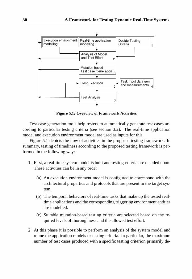
Figure 5.1: Overview of Framework Activities
Test case generation tools help testers to automatically generate test cases ac-cording to particular testing criteria (see section 3.2). The real-time applicationmodel and execution environment model are used as inputs for this.
Figure 5.1 depicts the flow of activities in the proposed testing framework. Insummary, testing of timeliness according to the proposed testing framework is per-formed in the following way:
1. First, a real-time system model is built and testing criteria are decided upon.These activities can be in any order
(a) An execution environment model is configured to correspond with thearchitectural properties and protocols that are present in the target sys-tem.
(b) The temporal behaviors of real-time tasks that make up the tested real-time applications and the corresponding triggering environment entitiesare modelled.
(c) Suitable mutation-based testing criteria are selected based on the re-quired levels of thoroughness and the allowed test effort.
2. At this phase it is possible to perform an analysis of the system model andrefine the application models or testing criteria. In particular, the maximumnumber of test cases produced with a specific testing criterion primarily de-

5.2 Timeliness Test Cases 31
Real-time Sys. Model
Testing Criteria
Mutation-based Test Case Generation
Input data models
Measurements/Static Analysis
Task Code
Task Input Data Activation Patterns+Execution Orders
Timeliness Test Cases
Figure 5.2: Timeliness tests overview
pends on the size of the system. The analysis of the model and testing criteriamay result in refinements before proceeding with test generation.
3. Test cases are generated automatically from the model in accordance withthe selected testing criterion. Based on the result of the automated test casegeneration, the testing criterion may also be changed.
4. Sets of input data for individual tasks are acquired using compiler basedmethods or temporal unit testing with measurements.
5. Each generated test case is executed repeatedly to capture different behaviorsof the non-deterministic platform. Prefix-based test execution techniques canbe used if the test harness and target platform supports it.
6. During test execution, the test harness produces logs that can be analyzedoff-line to further refine the model or isolate timeliness faults. If a particu-lar execution order has not been sufficiently covered more test-runs can beperformed. The real-time system model, the implementation or testing crite-ria can be refined based on the test results and a new iteration of timelinesstesting can be started.
5.2 Timeliness Test Cases
Figure 5.2 shows an overview of the data flow when generating timeliness testcases. Information from the real-time application model and execution environment

32 A Framework for Testing Dynamic Real-Time Systems
model, as explained in section 5.1, is used for generating activation patterns andexecution orders.
Activation patternsare time-stamped sequences of requests for task activation.For example, an activation pattern may express that task A should be activated attimes 5, 10, and 14 while task B should be activated at times 12, 17 and 23.
The execution order part of test cases predicts how tasks are interleaved in asituation where timeliness may be violated for a particular activation pattern. Thisis sometimes referred to as acritical execution order. The execution orders can beused to derive a test prefix (see section 5.4) for test execution; it can also be usedduring test analysis to determine if a test run has revealed a dangerous behavior.
Timeliness test cases should also specify relevant input data for the varioustasks so that their execution behavior can be, at least partially, controlled duringtimeliness testing.Task input data, in this context, are the values that are readby tasks throughout their execution. For example, a task for controlling the tem-perature in a chemical process might read the current temperature from a memorymapped I/O port and the desired temperature from a shared data structure. Boththese values influence the control flow of the task and, thus, decide the executionbehavior of the task. Typically, it is interesting to use input data that cause longexecution times or cause shared resources to be used a long time.
There are several ways of obtaining such input data for tasks running undis-turbed. For example, Wegener, StHammer, Jones & Eyres (1997) applied a methodbased on genetic algorithms to acquire test data for real-time tasks. Petters & Farber(1999) used compiler based analysis for the same purpose. Further, deriving taskinput data is similar to deriving input data for unit testing of sequential software;hence, methods from that domain can be adapted to ensure a wide range of exe-cution behaviors is covered. Common to all such approaches is that they requirethe actual implementation and information about the input domain of tasks. Hence,these requirements are inherited by the framework for testing of timeliness. Inthis thesis, we assume that suitable input data for the various tasks are availableand focus on generating activation patterns and execution orders for testing systemtimeliness when several tasks execute concurrently.
5.3 Mutation-based Test Case Generation
Mutation-based testing of timeliness is inspired by a specification-based methodfor automatic test case generation presented by Ammann, Black and Majurski(Ammann, Black & Majurski. 1998). The main idea behind the method is to sys-
5.3 Mutation-based Test Case Generation 33
TestingCriterion
Real-timesystemmodel
Mutantgenerator
MutationOperators
ExecutionAnalysis
Killed mutants+Traces
Mutantmodels
Traceprocessing
Activationpatterns+Exec. orders
Figure 5.3: Mutation-based test case generation
tematically “guess” what faults a system contains and then evaluate what the effectof such a fault would be. Once faults with severe consequences are identified,specialized test cases are constructed that aim to reveal such faults in the systemimplementation.
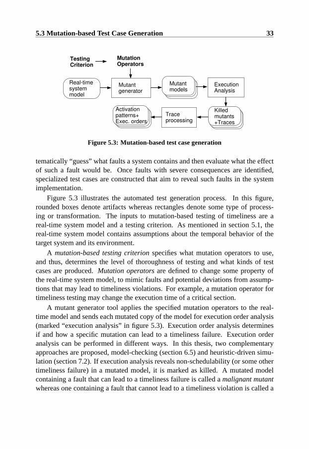
Figure 5.3 illustrates the automated test generation process. In this figure,rounded boxes denote artifacts whereas rectangles denote some type of process-ing or transformation. The inputs to mutation-based testing of timeliness are areal-time system model and a testing criterion. As mentioned in section 5.1, thereal-time system model contains assumptions about the temporal behavior of thetarget system and its environment.
A mutation-based testing criterionspecifies what mutation operators to use,and thus, determines the level of thoroughness of testing and what kinds of testcases are produced.Mutation operatorsare defined to change some property ofthe real-time system model, to mimic faults and potential deviations from assump-tions that may lead to timeliness violations. For example, a mutation operator fortimeliness testing may change the execution time of a critical section.
A mutant generator tool applies the specified mutation operators to the real-time model and sends each mutated copy of the model for execution order analysis(marked “execution analysis” in figure 5.3). Execution order analysis determinesif and how a specific mutation can lead to a timeliness failure. Execution orderanalysis can be performed in different ways. In this thesis, two complementaryapproaches are proposed, model-checking (section 6.5) and heuristic-driven simu-lation (section 7.2). If execution analysis reveals non-schedulability (or some othertimeliness failure) in a mutated model, it is marked as killed. A mutated modelcontaining a fault that can lead to a timeliness failure is called amalignant mutantwhereas one containing a fault that cannot lead to a timeliness violation is called a

34 A Framework for Testing Dynamic Real-Time Systems
Test Harness
Test ObjectTimelinessTest case
Test Outcome
Expected Outcome
Test Result
Test Execution Test Analysis
Figure 5.4: Timeliness test execution overview
benign mutant. Ideally, an execution order analyzer should always be able to kill allmalignant mutants. Traces from killed mutated models are used to extract an acti-vation pattern with the ability to reveal faults similar to the malignant mutant modelin the system under test. It is also possible to extract the corresponding executionorder of tasks that leads to deadline violations from such traces.
5.4 Test Execution
Figure 5.4 shows the components and artifacts associated with test execution andtest analysis.
Test executionis the process of running the target system and injecting stim-uli according to the activation pattern part of the timeliness test case. Since thetarget platform contain sources of non-determinism, several execution orders mayoccur in the real system for the same activation pattern. Consequently, a minimalrequirement for applying the testing framework is that each activation pattern au-tomatically can be injected repeatedly (see section 3.3). Each single execution ofa test case is called atest run(that is, a test case execution may consist of one ormore test runs). The outputs collected from the system during test execution arecollectively called atest outcome.
The execution orders from test cases provide the ability to determine when a po-tentially critical execution order has been reached. Optionally, more advanced testexecution mechanisms, such as prefix-based testing (Hwang, Tai & Hunag 1995),can be used to increase the controllability during test execution. In that case, thesystem is initialized in a specified prefix state before each test run starts, increasingthe probability that a particular execution order can be observed. A discussion ofhow this kind of test execution can be supported for timeliness testing, is availablein section 10.3.2.
The test harnessincorporates all the software needed for controlling and ob-
5.4 Test Execution 35
serving a test execution of the target system. The design of the test harness iscritical for real-time systems since parts of it must typically be left in the opera-tional system to avoid probe effects (see section 3.3). To be specific, the test objectin figure 5.4 is the part of the target system that is being tested.
During test analysis, the test outcome produced by the system during test ex-ecution is analyzed with respect to the expected outcome. Atest resultindicateswhether a test execution succeeded in revealing an error or not. For timelinesstesting, the most relevant test outcomes are the execution orders and temporal be-havior observed during a test run. Expected outcomes are that the specified timingconstraints are met and, optionally, that no critical execution order is observed. Ifmutation-based testing has been used to generate a test case, then both the mutatedand original models can be used for test analysis.
Test analysis can be made both off-line or on-line. One motivation for off-linetest analysis is to avoid probe-effects, another is that more resources are typicallyavailable for the algorithms which process the test outcome. It might also be easierto predict the expected correct behavior after certain variables have been instanti-ated during the test run. The advantage of on-line test analysis is that test results canbe acquired at run-time, making it possible to perform error handling or capture ad-ditional data for debugging. The software that performs test analysis is sometimescalled atest oracle.

36 A Framework for Testing Dynamic Real-Time Systems

Chapter 6
Mutation-based Testing Criteriafor Timeliness
This chapter introduces mutation-based testing criteria for testing of timeliness.In addition, a method for automated test case generation using these criteria isdescribed.
6.1 Motivation
As mentioned in section 3.2, testing criteria are used to specify goals for testing.Further, when a testing activity is limited in time, testing criteria are useful forreporting the achieved level of coverage for each tested module or property. Forexample, a test report may state that a module has been tested up to 78 percentstatement coverage, or that 85 percent of all pairwise combinations of startup para-meters have been tested.
In the same way, it is useful to be able to state to what degree system timelinesshas been tested. However, if conventional testing criteria for sequential softwareare applied on all possible execution orders of a dynamic real-time system (as sug-gested for statically scheduled systems (Thane 2000)), then it becomes practicallyimpossible to reach full coverage. The reason for this is the exponential growthof execution orders in event-triggered systems (Schutz 1993). Hence, covering allexecution orders in dynamic real-time systems is generally unfeasible and compa-rable to full path coverage of sequential software.
Less ambitious and yet effective test criteria are needed for testing dynamicreal-time systems. Further, it is desirable to focus testing efforts on the execution
37

38 Mutation-based Testing Criteria for Timeliness
orders where small deviations in assumptions may cause timeliness violations.To formulate such testing criteria and generate test cases automatically, a no-
tation for modelling dynamic real-time systems is needed, as described in section6.2. Based on this notation, mutation operators and corresponding testing criteriaare defined in sections 6.3 and 6.4 respectively. Section 6.5 describes our methodfor generating timeliness test cases using model-checking; this method is subse-quently used in a evaluation experiment described in section 6.6.
6.2 Adopted Modelling Formalism
The Timed Automata (TA) (Alur & Dill 1994) notation has been used to modeldifferent aspects of real-time systems and to generate test cases that do not take ex-ecution orders and platform information into consideration (e.g., Petitjean & Fochal(1999)). An extension of timed automata, Timed Automata with Tasks (TAT) waspresented by Norstrom, Wall and Yi (Norstrom, A.Wall & Yi 1999) and refined byFersman et al. (Fersman, Pettersson & Yi 2002) (Fersman 2003). TAT includesexplicit means of modelling scheduling and execution behavior of concurrent real-time tasks, so it is suitable as a source for mutation-based testing of timeliness.
A timed automaton (TA) is a finite state machine extended with a collectionof real-valued clocks. Each transition can have a guard, an action and a numberof clock resets. A guard is a condition on clocks and variables, such as a timeconstraint. An action makes calculations, resets clocks and assigns values to vari-ables. The clocks increase uniformly from zero until they are individually reset byan action. When a clock is reset, it is instantaneously set to zero and then starts toincrease uniformly with the other clocks. TAT extends the TA notation with a setof real-time tasks P. The elements of the set P represent tasks that perform com-putations in response to an activation request. Formally, we use definition 6.1 fromFersman (2003). In her definition,Act is a finite set of actions andζ a finite set ofreal-valued variables for clocks.B(ζ) denotes the set of conjunctive formulae ofatomic constraints in the formxi ∼ C or xi−xj ∼ D wherexi, xj ∈ ζ are clocks,∼ ∈ {≤, <, =,≥, >} and C & D are natural numbers.
Definition 6.1 A timed automaton extended with tasks over actionsAct, clocksζand tasksP is a tuple< N, l0, E, I, M > where
• < N, l0, E, I > is a timed automaton where
– N is a finite set of locations– l0 ∈ N is the initial location– E ⊆ N ×B(ζ)×Act× 2ζ ×N

6.2 Adopted Modelling Formalism 39
ID c d SEM PRECA 4 12 {} {}B 2 8 {} {}
Table 6.1: Task set for example TAT
– I : N 7→ B(ζ) is a function assigning each location with a clockconstraint
• M : N 7→ P is a partial function assigning locations to tasks inP
A state in TAT is defined by a triple consisting of the current location of theautomaton, instantiations for all data variables and clocks, and a task queue. Thetask queue contains tuples with the remaining execution time as well as the timeremaining until the deadline is reached for each task instance. The first task instancein the queue is assumed to be executing and its remaining execution time decreaseswhen the clocks progress. A task instance is placed into the task queue when alocation associated with the task is reached. If the remaining execution time reaches0 for the first task in the queue, it is removed, and the next task starts to execute.Preemptions occur when the first task in the queue is replaced before its remainingexecution time is zero. Parallel decomposition of multiple TA and TAT automatacan be done with synchronization functions (Fersman 2003).
Shared resources are modelled by a set of system-wide semaphores,R, whereeach semaphores ∈ R can be locked and unlocked by tasks at fixed points in time,0 ≤ t1 < t2 ≤ ci, relative to the task’s start time. Elements inP express infor-mation about task types as quadruples(c, d, SEM, PREC). The variablec isthe required execution time andd is the relative deadline. These values are used toinitialize the remaining execution time and time until deadline when a new instanceis put in the task queue. The setSEM contain tuples of the form(s, t1, t2) wheret1 andt2 are the lock and unlock times of semaphores ∈ R relative to the starttime of the task. In this notation, precedence constraints are modelled as relationsbetween pairs of tasks, hence,PREC is a subset ofP that specifies which tasksmust precede a task of this type.
The precedence constraints and semaphore requirements impact the task queueso that only tasks with their execution conditions fulfilled can be put in the firstposition of the schedule (Fersman et al. 2002).
As an example, consider the TAT model in figure 6.1, and the simple task setin table 6.1. All clocks start at zero, the task queue starts empty and the automatonis in the Initial location. Two types of transitions may occur: (i) time may progressan arbitrary time period (delay transitions), increasing all clock variables, or (ii) atransition to location Alpha can be taken (an action transition). In this example, two
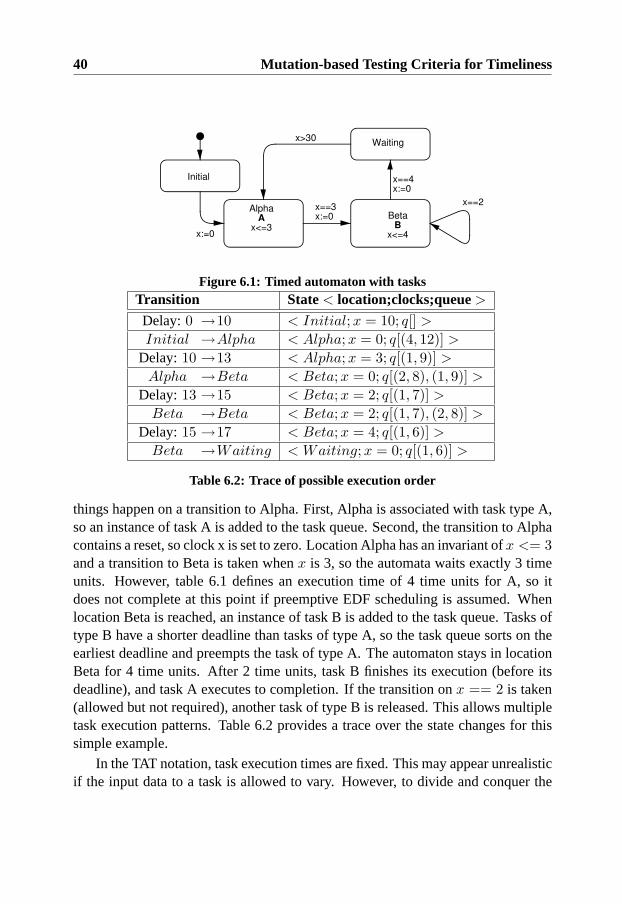
40 Mutation-based Testing Criteria for Timeliness
Initial
AlphaA
x<=3
x==3x:=0
Waiting
x==4x:=0
BetaB
x<=4x:=0
x>30
x==2
Figure 6.1: Timed automaton with tasksTransition State< location;clocks;queue>
Delay:0 →10 < Initial;x = 10; q[] >
Initial →Alpha < Alpha; x = 0; q[(4, 12)] >
Delay:10 →13 < Alpha; x = 3; q[(1, 9)] >
Alpha →Beta < Beta;x = 0; q[(2, 8), (1, 9)] >
Delay:13 →15 < Beta;x = 2; q[(1, 7)] >
Beta →Beta < Beta;x = 2; q[(1, 7), (2, 8)] >
Delay:15 →17 < Beta;x = 4; q[(1, 6)] >
Beta →Waiting < Waiting;x = 0; q[(1, 6)] >
Table 6.2: Trace of possible execution order
things happen on a transition to Alpha. First, Alpha is associated with task type A,so an instance of task A is added to the task queue. Second, the transition to Alphacontains a reset, so clock x is set to zero. Location Alpha has an invariant ofx <= 3and a transition to Beta is taken whenx is 3, so the automata waits exactly 3 timeunits. However, table 6.1 defines an execution time of 4 time units for A, so itdoes not complete at this point if preemptive EDF scheduling is assumed. Whenlocation Beta is reached, an instance of task B is added to the task queue. Tasks oftype B have a shorter deadline than tasks of type A, so the task queue sorts on theearliest deadline and preempts the task of type A. The automaton stays in locationBeta for 4 time units. After 2 time units, task B finishes its execution (before itsdeadline), and task A executes to completion. If the transition onx == 2 is taken(allowed but not required), another task of type B is released. This allows multipletask execution patterns. Table 6.2 provides a trace over the state changes for thissimple example.
In the TAT notation, task execution times are fixed. This may appear unrealisticif the input data to a task is allowed to vary. However, to divide and conquer the

6.3 Mutation Operators 41
testing problem, the test case generation step assumes that each task is associatedwith a particular (typical or worst-case) equivalence class of input data (see thecase-study in chapter 9 for an example of how this can be handled).
6.3 Mutation Operators
As mentioned in section 5.3, the basis for mutation testing is the set of operators.Mutation operators usually model possible faults, therefore the first step in design-ing mutation operators is to understand the types of faults and errors that can leadto timeliness failures. We have identified two categories of timeliness faults.
The first category represents incorrect assumptions about the system behaviorduring schedulability analysis and design. This includes assumptions about thelongest execution paths, use of shared resources, precedence relations, overheadtimes and cache efficiency. If the wrong assumptions are used then unforseen ex-ecution orders may cause deadlines to be missed. Furthermore, incorrect assump-tions about task attributes may result in incorrect behavior of admission control andoverload management protocols used in more complex real-time system architec-tures (for example, as described by Hansson, Son, Stankovic & Andler (1998)).
The second category represents the system’s ability to cope with unanticipateddiscontinuities and changes in the load, for example, disturbances in the samplingor in the constraints on the activation patterns of sporadic tasks. Faults of this typemay come either from the implementation of the mechanism that trigger task execu-tion, or from incorrect modelling of the operational environment. If the operationalenvironment differs from the assumptions, even an extensively tested system mayfail during operation.
Mutation operators based on these two categories are described in this section.For six operators, a parameter is used to indicate constant differences in time. Thistime can be tuned by the tester to yield mutants that are easier or harder to kill,hence,∆ is used to denote the size of the change. In the following descriptions, thevariablen denotes the number of tasks in the system’s task set andr is the numberof shared resources requiring mutual exclusion. In some systems, the same resourceis locked and released multiple times by the same task (for example, to decreaseblocking times), thereforel denotes the maximum number of times a resource islocked by the same task.
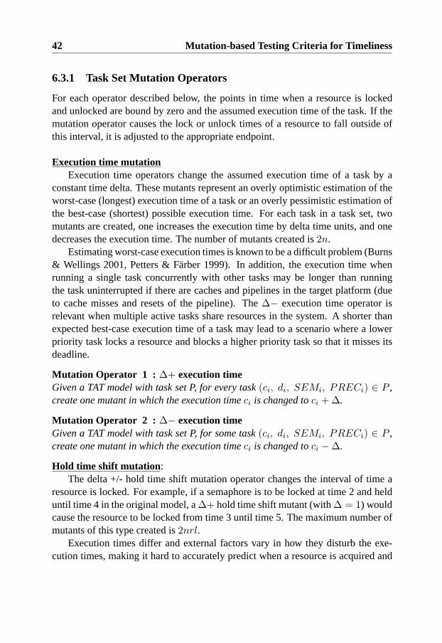
42 Mutation-based Testing Criteria for Timeliness
6.3.1 Task Set Mutation Operators
For each operator described below, the points in time when a resource is lockedand unlocked are bound by zero and the assumed execution time of the task. If themutation operator causes the lock or unlock times of a resource to fall outside ofthis interval, it is adjusted to the appropriate endpoint.
Execution time mutationExecution time operators change the assumed execution time of a task by a
constant time delta. These mutants represent an overly optimistic estimation of theworst-case (longest) execution time of a task or an overly pessimistic estimation ofthe best-case (shortest) possible execution time. For each task in a task set, twomutants are created, one increases the execution time by delta time units, and onedecreases the execution time. The number of mutants created is2n.
Estimating worst-case execution times is known to be a difficult problem (Burns& Wellings 2001, Petters & Farber 1999). In addition, the execution time whenrunning a single task concurrently with other tasks may be longer than runningthe task uninterrupted if there are caches and pipelines in the target platform (dueto cache misses and resets of the pipeline). The∆− execution time operator isrelevant when multiple active tasks share resources in the system. A shorter thanexpected best-case execution time of a task may lead to a scenario where a lowerpriority task locks a resource and blocks a higher priority task so that it misses itsdeadline.
Mutation Operator 1 : ∆+ execution timeGiven a TAT model with task set P, for every task(ci, di, SEMi, PRECi) ∈ P ,create one mutant in which the execution timeci is changed toci + ∆.
Mutation Operator 2 : ∆− execution timeGiven a TAT model with task set P, for some task(ci, di, SEMi, PRECi) ∈ P ,create one mutant in which the execution timeci is changed toci −∆.
Hold time shift mutation :The delta +/- hold time shift mutation operator changes the interval of time a
resource is locked. For example, if a semaphore is to be locked at time 2 and helduntil time 4 in the original model, a∆+ hold time shift mutant (with∆ = 1) wouldcause the resource to be locked from time 3 until time 5. The maximum number ofmutants of this type created is2nrl.
Execution times differ and external factors vary in how they disturb the exe-cution times, making it hard to accurately predict when a resource is acquired and
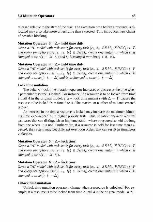
6.3 Mutation Operators 43
released relative to the start of the task. The execution time before a resource is al-located may also take more or less time than expected. This introduces new chainsof possible blocking.
Mutation Operator 3 : ∆+ hold time shiftGiven a TAT model with task set P, for every task(ci, di, SEMi, PRECi) ∈ Pand every semaphore use(s, t1, t2) ∈ SEMi, create one mutant in whicht1 ischanged tomin(t1 + ∆, ci) andt2 is changed tomin(t2 + ∆, ci).
Mutation Operator 4 : ∆− hold time shiftGiven a TAT model with task set P, for every task(ci, di, SEMi, PRECi) ∈ Pand every semaphore use(s, t1, t2) ∈ SEMi, create one mutant in whicht1 ischanged tomax(0, t1 −∆) andt2 is changed tomax(0, t2 −∆).
Lock time mutationThe delta +/- lock time mutation operator increases or decreases the time when
a particular resource is locked. For instance, if a resource is to be locked from time2 until 4 in the original model, a∆+ lock time mutant (with∆ = 1) causes theresource to be locked from time 3 to 4. The maximum number of mutants createdis 2nrl.
An increase in the time a resource is locked may increase the maximum block-ing time experienced by a higher priority task. This mutation operator requirestest cases that can distinguish an implementation where a resource is held too longfrom one where it is not. Furthermore, if a resource is held for less time than ex-pected, the system may get different execution orders that can result in timelinessviolations.
Mutation Operator 5 : ∆+ lock timeGiven a TAT model with task set P, for every task(ci, di, SEMi, PRECi) ∈ Pand every semaphore use(s, t1, t2) ∈ SEMi, create one mutant in whicht1 ischanged tomin(t1 + ∆, t2).
Mutation Operator 6 : ∆− lock timeGiven a TAT model with task set P, for every task(ci, di, SEMi, PRECi) ∈ Pand every semaphore use(s, t1, t2) ∈ SEMi, create one mutant in whicht1 ischanged tomax(0, t1 −∆).
Unlock time mutationUnlock time mutation operators change when a resource is unlocked. For ex-
ample, if a resource is to be locked from time 2 until 4 in the original model, a∆+
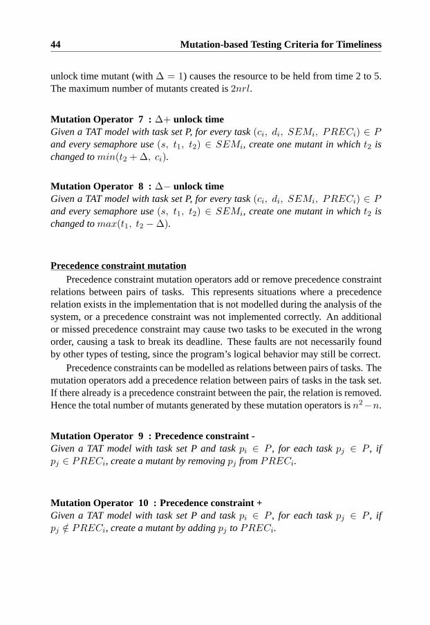
44 Mutation-based Testing Criteria for Timeliness
unlock time mutant (with∆ = 1) causes the resource to be held from time 2 to 5.The maximum number of mutants created is2nrl.
Mutation Operator 7 : ∆+ unlock timeGiven a TAT model with task set P, for every task(ci, di, SEMi, PRECi) ∈ Pand every semaphore use(s, t1, t2) ∈ SEMi, create one mutant in whicht2 ischanged tomin(t2 + ∆, ci).
Mutation Operator 8 : ∆− unlock timeGiven a TAT model with task set P, for every task(ci, di, SEMi, PRECi) ∈ Pand every semaphore use(s, t1, t2) ∈ SEMi, create one mutant in whicht2 ischanged tomax(t1, t2 −∆).
Precedence constraint mutationPrecedence constraint mutation operators add or remove precedence constraint
relations between pairs of tasks. This represents situations where a precedencerelation exists in the implementation that is not modelled during the analysis of thesystem, or a precedence constraint was not implemented correctly. An additionalor missed precedence constraint may cause two tasks to be executed in the wrongorder, causing a task to break its deadline. These faults are not necessarily foundby other types of testing, since the program’s logical behavior may still be correct.
Precedence constraints can be modelled as relations between pairs of tasks. Themutation operators add a precedence relation between pairs of tasks in the task set.If there already is a precedence constraint between the pair, the relation is removed.Hence the total number of mutants generated by these mutation operators isn2−n.
Mutation Operator 9 : Precedence constraint -Given a TAT model with task set P and taskpi ∈ P , for each taskpj ∈ P , ifpj ∈ PRECi, create a mutant by removingpj fromPRECi.
Mutation Operator 10 : Precedence constraint +Given a TAT model with task set P and taskpi ∈ P , for each taskpj ∈ P , ifpj /∈ PRECi, create a mutant by addingpj to PRECi.
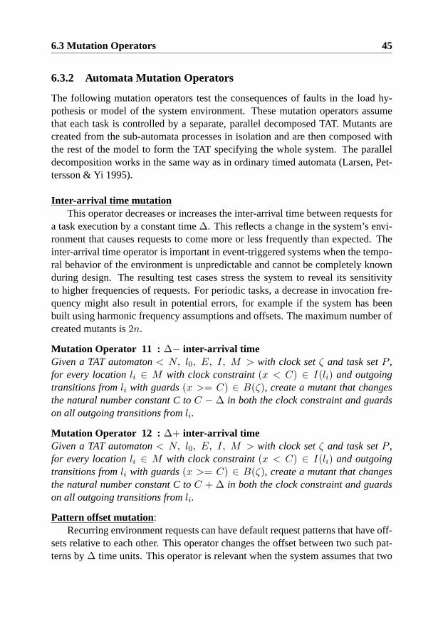
6.3 Mutation Operators 45
6.3.2 Automata Mutation Operators
The following mutation operators test the consequences of faults in the load hy-pothesis or model of the system environment. These mutation operators assumethat each task is controlled by a separate, parallel decomposed TAT. Mutants arecreated from the sub-automata processes in isolation and are then composed withthe rest of the model to form the TAT specifying the whole system. The paralleldecomposition works in the same way as in ordinary timed automata (Larsen, Pet-tersson & Yi 1995).
Inter-arrival time mutationThis operator decreases or increases the inter-arrival time between requests for
a task execution by a constant time∆. This reflects a change in the system’s envi-ronment that causes requests to come more or less frequently than expected. Theinter-arrival time operator is important in event-triggered systems when the tempo-ral behavior of the environment is unpredictable and cannot be completely knownduring design. The resulting test cases stress the system to reveal its sensitivityto higher frequencies of requests. For periodic tasks, a decrease in invocation fre-quency might also result in potential errors, for example if the system has beenbuilt using harmonic frequency assumptions and offsets. The maximum number ofcreated mutants is2n.
Mutation Operator 11 : ∆− inter-arrival timeGiven a TAT automaton< N, l0, E, I, M > with clock setζ and task setP ,for every locationli ∈ M with clock constraint(x < C) ∈ I(li) and outgoingtransitions fromli with guards(x >= C) ∈ B(ζ), create a mutant that changesthe natural number constant C toC − ∆ in both the clock constraint and guardson all outgoing transitions fromli.
Mutation Operator 12 : ∆+ inter-arrival timeGiven a TAT automaton< N, l0, E, I, M > with clock setζ and task setP ,for every locationli ∈ M with clock constraint(x < C) ∈ I(li) and outgoingtransitions fromli with guards(x >= C) ∈ B(ζ), create a mutant that changesthe natural number constant C toC + ∆ in both the clock constraint and guardson all outgoing transitions fromli.
Pattern offset mutation:Recurring environment requests can have default request patterns that have off-
sets relative to each other. This operator changes the offset between two such pat-terns by∆ time units. This operator is relevant when the system assumes that two
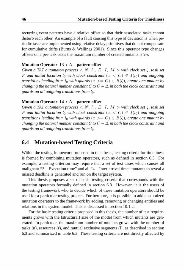
46 Mutation-based Testing Criteria for Timeliness
recurring event patterns have a relative offset so that their associated tasks cannotdisturb each other. An example of a fault causing this type of deviation is when pe-riodic tasks are implemented using relative delay primitives that do not compensatefor cumulative drifts (Burns & Wellings 2001). Since this operator type changesoffsets on a per-task basis the maximum number of created mutants is2n.
Mutation Operator 13 : ∆+ pattern offsetGiven a TAT automaton process< N, l0, E, I, M > with clock setζ, task setP and initial location l0 with clock constraint(x < C) ∈ I(l0) and outgoingtransitions leading froml0 with guards(x >= C) ∈ B(ζ), create one mutant bychanging the natural number constant C toC + ∆ in both the clock constraint andguards on all outgoing transitions froml0.
Mutation Operator 14 : ∆− pattern offsetGiven a TAT automaton process< N, l0, E, I, M > with clock setζ, task setP and initial location l0 with clock constraint(x < C) ∈ I(l0) and outgoingtransitions leading froml0 with guards(x >= C) ∈ B(ζ), create one mutant bychanging the natural number constant C toC −∆ in both the clock constraint andguards on all outgoing transitions froml0.
6.4 Mutation-based Testing Criteria
Within the testing framework proposed in this thesis, testing criteria for timelinessis formed by combining mutation operators, such as defined in section 6.3. Forexample, a testing criterion may require that a set of test cases which causes allmalignant “2+ Execution time” and all “4− Inter-arrival time” mutants to reveal amissed deadline is generated and run on the target system.
This thesis proposes a set of basic testing criteria that corresponds with themutation operators formally defined in section 6.3. However, it is the users ofthe testing framework who to decide which of these mutation operators should beused for a particular testing project. Furthermore, it is possible to add customizedmutation operators to the framework by adding, removing or changing entities andrelations in the system model. This is discussed in section 10.1.2.
For the basic testing criteria proposed in this thesis, the number of test require-ments grows with the (structural) size of the model from which mutants are gen-erated. In particular, the maximum number of mutants grows with the number oftasks (n), resources (r), and mutual exclusive segments (l), as described in section6.3 and summarized in table 6.3. These testing criteria are not directly affected by

6.4 Mutation-based Testing Criteria 47
Mutation operator type Max. Mutants
Execution time n
Hold time shift nrl
Lock time nrl
Unlock time nrl
Precedence constraint n2
Inter-arrival time n
Pattern offset n
Table 6.3: Maximum number of mutants generated by each operator
the size of the reachable state space1 of the real-time system model or the imple-mentation and, therefore, an exponential increase of test requirements (things tocover) is avoided. An effect of this is that mutation-based testing criteria are morescalable for dynamic real-time systems than testing criteria which require a fractionof all execution orders to be covered.
Since the model used for test case generation is based on assumptions aboutthe system under test, and not the structure or implementation of the real system, itis possible that the actual mutations of the model correspond with real differencesbetween the model and the implementation (timeliness errors). Hence, if mutationoperators correspond to deviations that are likely to occur and might lead to time-liness violations, then test cases are generated that target these types of faults. Thisrelation between mutants and implementation faults makes it desirable to have acomprehensible set of mutation operators.Comprehensivenessmeans that for alltypes of errors which might lead to timeliness violations in a particular system,there is a corresponding mutation operator. However, it is difficult to reach a com-prehensive set of meaningful mutation operators, especially since the combined ap-plication of mutation operators that individually cannot create malignant mutantsmay become meaningful. In this context, a mutation operator ismeaningfulif itcreates at least one malignant mutant. Further, there might be several fault typesthat are specific for a particular execution environment mechanism or design style.Examples of such mutation operators, and guidelines for how to extend the testingframework with new mutation operators are presented in section 10.1.
Similar to other types of mutation-based testing, mutation-based testing oftimeliness relies on the assumption that the generated test cases are also useful
1The reachable state space of a state machine (or program) is comprised of all states that mightbe reached from the initial state, given any possible input (Fersman 2003)

48 Mutation-based Testing Criteria for Timeliness
for detecting faults that do not exactly correspond to any mutant (see section 3.1).
6.5 Generation of Test Cases Using Model-Checking
Given a real-time system specified in TAT and an implementation of the aforemen-tioned mutation operators, model-checking can be used to kill mutants, that is, find-ing a trace that shows how a task in the mutated model violates a time constraint.The mechanism that makes this possible is the generic schedulability analysis usingTAT model-checking described by Fersman et al (Fersman et al. 2002). This mech-anism is implemented in the Times tool, developed at Uppsala University (Amnell,Fersman, Mokrushin, Pettersson & Yi 2002).
Once a real-time system has been modelled in TAT, an implementation of themutation operators, defined in section 6.3, automatically produce each mutant andsend it to the model checker for schedulability analysis. If the mutant is malignantthe schedulablility analysis results in a trace of transitions over the automata modelthat leads to a violated timing constraint.
From a timeliness testing perspective, the points in time in which different spo-radic tasks are requested are interesting to use as activation patterns (a part of time-liness test cases, as defined in section 5.2). Hence, by parsing the automata trace itis possible to extract the points in time where stimuli should be injected in order toreveal a fault in a system represented by the mutated model.
In the trace from TAT model-checker, such points are characterized by tran-sitions to task activation locations (that is, a locationli whereM(li) maps to anelement inP ). For each such transition, the task associated with the activationlocation,M(li), together with the current global time, are added to the activationpattern part of the derived test case.
The same trace contains information of how the system is assumed to behaveinternally for the timeliness failure to occur. This can be extracted by monitoringthe state changes over the set of active tasks in the ready queue (see table 6.2 for anexample). This information can be used during test case execution and test analysis,as described in section 5.2.
The main advantage with this approach is that, theoretically, if a mutant ismalignant it is killed by the model-checker, given sufficient time and resources forthe analysis.
The model-checking approach for generating test cases can be used with ar-bitrary complex automata modelling constraints on task activation patterns (in theenvironment of the real-time system) without changing the modelling notation or

6.6 Validation of Mutation Operators 49
model-checker implementation. This makes it possible to model systems wheresome sporadic tasks always arrive in clusters and others never occur at the sametime. Hence, the test cases generated with this approach comply to or are close tothe operational worst-cases of a system instead of artificial constraints on activationpatterns such as minimum inter-arrival times.
However, when system models increase in size and a larger fraction of trig-gering automata becomes more non-deterministic, the analysis performed by themodel-checker suffers from reachable state space explosion. A further limitationof the model-checking approach is the assumption that the target system complieswith a limited set of execution environment models supported by the model-checkertool. If the execution environment model must be changed, that change must bedone in the “back-end” of the model-checker2. It is unclear how such changesaffect the effectiveness of schedulability analysis.
6.6 Validation of Mutation Operators
To validate that the proposed mutation operators are meaningful a test case gener-ation experiment was performed. If mutants are killed with this approach it meansthe faults introduced in the model indeed represent faults that may cause timelinessviolation in a real-time system.
This case study uses a small task set that has a simple environment model butrelatively complex interactions between the tasks. Static priorities were assigned tothe tasks using thedeadline monotonic scheme, that is, the highest priority is givento the task with the earliest relative deadline. Arbitrary preemption is allowed.
The model-checker implements a variant of theimmediate priority ceilingpro-tocol to avoid priority inversion. That is, if a task locks a resource then its prioritybecomes equal to the priority of the highest priority task which might use that re-source, and is always scheduled before lower prioritized tasks. The FCFS policy isused if several tasks have the same priority.
The model has five tasks. Two are controlled by TAT models such as the onein figure 6.2. The automata are sporadic in nature but have a fixed observation grid(denoted OG in the figure), which limits when a new task instance can be released(for example, such a limitation may exist if requests may only arrive at certain slotsof a time-triggered network). These experiments use an observation grid of 10 timeunits. The three remaining tasks are strictly periodic and controlled by generic
2In the Times tool, some changes of this type can be done by exporting the execution environmentmodel to the Uppaal model-checker
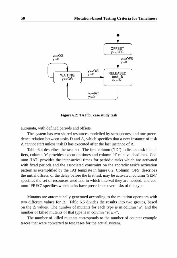
50 Mutation-based Testing Criteria for Timeliness
OFFSETy<=OFS
RELEASEDtask_By<=IAT
WAITINGy<=OG
y>=OFSy:=0
y>=IATy:=0
y>=OGy:=0
y>=OGy:=0
Figure 6.2: TAT for case study task
automata, with defined periods and offsets.The system has two shared resources modelled by semaphores, and one prece-
dence relation between tasks D and A, which specifies that a new instance of taskA cannot start unless task D has executed after the last instance of A.
Table 6.4 describes the task set. The first column (’ID’) indicates task identi-fiers, column ’c’ provides execution times and column ’d’ relative deadlines. Col-umn ’IAT’ provides the inter-arrival times for periodic tasks which are activatedwith fixed periods and the associated constraint on the sporadic task’s activationpattern as exemplified by the TAT template in figure 6.2. Column ’OFS’ describesthe initial offsets, or the delay before the first task may be activated, column ’SEM’specifies the set of resources used and in which interval they are needed, and col-umn ’PREC’ specifies which tasks have precedence over tasks of this type.
Mutants are automatically generated according to the mutation operators withtwo different values for∆. Table 6.5 divides the results into two groups, basedon the∆ values. The number of mutants for each type is in column ‘µ’, and thenumber of killed mutants of that type is in column “KMC”.
The number of killed mutants corresponds to the number of counter exampletraces that were converted to test cases for the actual system.
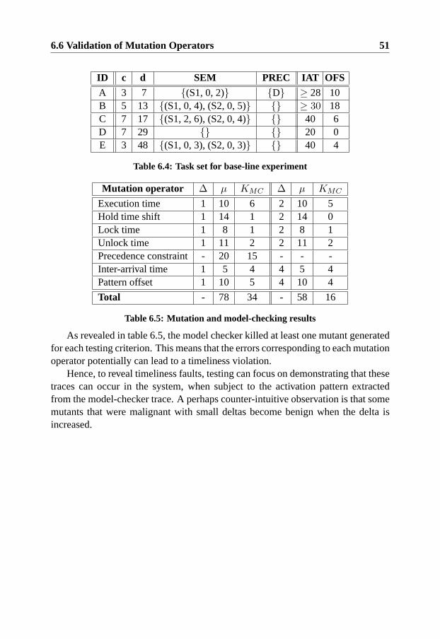
6.6 Validation of Mutation Operators 51
ID c d SEM PREC IAT OFS
A 3 7 {(S1, 0, 2)} {D} ≥ 28 10B 5 13 {(S1, 0, 4), (S2, 0, 5)} {} ≥ 30 18C 7 17 {(S1, 2, 6), (S2, 0, 4)} {} 40 6D 7 29 {} {} 20 0E 3 48 {(S1, 0, 3), (S2, 0, 3)} {} 40 4
Table 6.4: Task set for base-line experiment
Mutation operator ∆ µ KMC ∆ µ KMC
Execution time 1 10 6 2 10 5Hold time shift 1 14 1 2 14 0Lock time 1 8 1 2 8 1Unlock time 1 11 2 2 11 2Precedence constraint - 20 15 - - -Inter-arrival time 1 5 4 4 5 4Pattern offset 1 10 5 4 10 4
Total - 78 34 - 58 16
Table 6.5: Mutation and model-checking results
As revealed in table 6.5, the model checker killed at least one mutant generatedfor each testing criterion. This means that the errors corresponding to each mutationoperator potentially can lead to a timeliness violation.
Hence, to reveal timeliness faults, testing can focus on demonstrating that thesetraces can occur in the system, when subject to the activation pattern extractedfrom the model-checker trace. A perhaps counter-intuitive observation is that somemutants that were malignant with small deltas become benign when the delta isincreased.

52 Mutation-based Testing Criteria for Timeliness
Chapter 7
Generation of Test Cases UsingHeuristic-driven Simulations
This section presents an alternative method for generating mutation-based test casesthat are suitable for flexible real-time systems.
7.1 Motivation
In chapter 6 model-checking of TAT specifications is used for the execution orderanalysis step of test case generation. This is possible since the counter-examplesfrom schedulability analysis shows the execution orders that can lead to misseddeadlines. Model-checking is a reliable method in the sense that timeliness vio-lations are guaranteed to be revealed if they exist in the mutated model and themodel-checker terminates. However, for large task sets the computational complex-ity of this type of analysis often becomes too great. In particular, the complexity ofanalysis increases if many tasks use shared resources and are released in responseto sporadic requests1.
In dynamic real-time systems, there is potential for many sporadic tasks and,thus model-checking may be impractical. We propose an approach for testing time-liness of such systems where a simulation of the mutant model is iteratively runand evaluated using heuristics. By using a simulation-based method instead ofmodel-checking for execution order analysis, the combinatorial explosion of full
1In TAT-models, each activation automaton for a sporadic task would require at least one localclock, this is known to increase analysis complexity.
53
54 Generation of Test Cases Using Heuristic-driven Simulations
state exploration is avoided.Further, we assume that it is less time consuming to modify a system simulation
to correspond with the execution environment model, compared to changing themodel-checker in such a way that schedulability analysis remains feasible.
The transition from model-checking to simulation can be compared with a simi-lar trend in automatic test data generation for sequential software, where constraint-solving (DeMillo & Offutt 1991) has been successfully complemented with dy-namic approaches in which actual software executions guide the search for inputvalues (Offutt, Jin & Pan 1999).
When simulation is used for execution order analysis, the TAT model task setis mapped to corresponding task and resource entities in a real-time simulator. Theactivation patterns of periodic tasks are known beforehand and are included into thestatic configuration of the simulator. The activation pattern for sporadic (automatacontrolled) tasks is varied for each simulation to find the execution orders that canlead to timeliness failures.
Consequently, a necessary input to the simulation of a particular system (cor-responding to a TAT model) is an activation pattern of the sporadic tasks. Therelevant output from the simulation is an execution order trace over a hyper-period(see section 3.4) of the periodic tasks where the sporadic requests have been in-jected according to the activation pattern. A desired output from a mutation testingperspective is an execution order that leads to a timing constraint being violated.
By treating test case generation as an heuristic search problem, different heuris-tic methods can be applied to find a feasible solution. In the following sections, wepresent and evaluate an approach based on genetic algorithms.
7.2 Genetic Algorithms for Test case Generation
Genetic algorithms (also known as evolutionary algorithms (Michalewicz & Fogel1998)) are suggested for the heuristic search of TAT models, since they are config-urable and are known for coping well with search spaces containing local optima(Michalewicz & Fogel 1998).
Genetic algorithms operate by iteratively refining a set of solutions to an opti-mization problem through random changes and by combining features from exist-ing solutions. In the context of genetic algorithms, the solutions are calledindivid-ualsand the set of solutions is called thepopulation. Each individual has agenomethat represents its unique features in a standardized and compact format. Commonformats for genomes are bit-strings and arrays of real values. Consequently, users

7.2 Genetic Algorithms for Test case Generation 55
of a genetic algorithm tool-box must supply a problem specific mapping functionfrom a genome in any of the standard formats to a particular candidate solution forthe problem. It has been argued that the mapping is important for the success of thegenetic algorithm. For example, it is desirable that all possible genomes representa valid solution (Michalewicz & Fogel 1998).
The role of the fitness function in genetic algorithms is to evaluate the opti-mality or fitnessof a particular individual. The individuals with the highest levelof fitness in a population and are more likely to be selected as input to cross-overfunctions and of being moved to the next generation.
Cross-over functions are applied on the selected individuals to create new in-dividuals with higher fitness in the next generation. This means either combiningproperties from several individuals, or modifying a single individual according toheuristics. Traditionally, a function applied on a single individual is called a “mu-tation” but to avoid ambiguity2 we use the termcross-over functionsfor all thefunctions that result in new genomes for the next generation.
There are generic cross-over functions that operate on arbitrary genomes ex-pressed in the standard formats. For example, a cross-over function can exchangetwo sub-strings in a binary string genome or increase some random real value in anarray. However, depending on the encoding of genomes, the standard cross-overfunctions may be more or less successful in enhancing individuals. Using knowl-edge of the problem domain and the mapping function, it is possible to customizecross-over functions in a way that increases the probability of creating individu-als with high fitness. On the other hand, some cross-over functions must remainstochastic to prevent the search from getting stuck in local optima. A genetic al-gorithm search typically continues for a predetermined number of generations, oruntil an individual that meets some stopping criteria has been found.
In general, three types of functions need to be defined to apply genetic algo-rithms to a specific search problem:(i) a genome mapping function,(ii) heuristiccross-over functions, and(iii) a fitness function. The following subsections suggestsuch functions for mutation-based timeliness test case generation.
The performance of a genetic algorithm can also be enhanced by preparing theinitial population with solutions that are assumed to have high fitness based onapplication knowledge. Since this type of initialization is system specific, it is notfully investigated in this thesis. However, some example enhancements of this typeare discussed in section 10.2.2.
2In this thesis, the term mutation refers to changes to a real-time system model that is done beforeexecution order analysis begins.

56 Generation of Test Cases Using Heuristic-driven Simulations
OFFSETy <= OFS(i)+T(i,1)
RELEASE Task iy <= MIAT(i)+T(i,j)y == OFS(i)+T(i,1)
y := 0
y == MIAT(i)+T(i,j)y := 0
Figure 7.1: Annotated TAT template}OFS(i) }T(i,1) }MIAT(i)
}T(i,2) }MIAT(i) }T(i,3)
a1 a2 a30
Figure 7.2: Activation pattern of sporadic task i
7.2.1 Genome Mapping Function
For the test case generation problem, only the activation patterns of non-periodictasks vary between consecutive simulations of the same TAT model. Thus, it issufficient that a genome can be mapped to such an activation pattern. Each acti-vation pattern deterministically results in a particular execution order trace in thesimulation. The execution order traces are the individuals for this search problem.
Figure 7.1 contains an annotated TAT-automata for describing activation pat-terns of sporadic tasks. Generally, activation patterns can be expressed by anytimed automata, but this mapping function uses sporadic task templates, sinceevent-triggered real-time tasks are often modelled as being sporadic (Burns &Wellings 2001). The template has two parameters that are constant for each mutant.The parameter OFS defines the assumed offset, that is, the minimum delay beforeany instance of this task is assumed to be requested. The parameter MIAT definesthe assumed minimum inter-arrival time between instances of the sporadic task.
An array of real valuesT(i,1..m) defines the duration of thevariable delay in-terval between consecutive requests of a sporadic taski. Herem is the maximumnumber of activations that can occur during the simulation. Figure 7.2 depicts thefirst three activations of a sporadic task and exemplifies the relation between theautomata constants and the values inT .
By combining the arrays forn sporadic tasks in the mutant task setP we forma matrixT(1..n,1..m) of real values, where each row corresponds to an activationpattern of a sporadic task. The matrixT can be used as a genome representation ofall valid activation patterns for the mutant model.

7.2 Genetic Algorithms for Test case Generation 57
7.2.2 Fitness Function
Since our genome representation of valid activation patterns is meaningless with-out a particular TAT-mutant model, the simulation must be run with the activationpattern matrix as input before fitness can be calculated. The fitness for each indi-vidual in a population is computed in three steps. First, a genome is translated to anactivation pattern of sporadic tasks. Second, a simulation of the mutant TAT modelis run in which the sporadic tasks are requested according to the activation pattern.
Third, the resulting execution order trace from the simulation is used to cal-culate fitness. A suitable fitness for the generation of timeliness test cases shouldexpress how close a mutant is to violating a time constraint. Theslackis the timebetween the response time of a task instance and its deadline (see section 2.2).Hence, measuring the minimum slack observed during a simulation is one of thesimplest ways of calculating fitness. The highest fitness is given to the activationpattern that results in the simulated execution order trace with the least minimumslack. More elaborate fitness functions (for example, using weighting based ondiversity or average response times) can also be evaluated for improving the per-formance of the genetic algorithm.
7.2.3 Heuristic Cross-over Functions
For timeliness testing, there are intuitive heuristics for what kind of activation pat-terns are likely to stress the mutant model. For example, it seems possible thatreleasing many different types of sporadic requests in a burst-like fashion is morelikely to reveal timeliness violations than an even distribution of requests.
The variableM is a TAT model that containsn sporadic tasks controlled byautomata templates such as in figure 7.1. As described in section 7.2.1, a genomematrix of sizen ∗ m is denoted by the variableT . The integer variablei is usedto index over the rows in a genome matrixT . The rows in such matrices corre-spond to sporadic tasks, hence it is bounded by1 andn. The integer variablejandk is used to index over the columns in genome matrices and is bounded by1 andm. The variableε is used to denote a small positive real number. The ex-pression[abeg, aend] v [bbeg, bend] means that the left hand interval[abeg, aend] is asub-interval of the right hand interval[bbeg, bend]. Formally, this can be expressed([abeg, aend] v [bbeg, bend]) ⇐⇒ (abeg ≥ bbeg ∧ aend ≤ bend).
Definition 7.1 : Critical task instanceThe task instance with the least slack in an execution order trace.
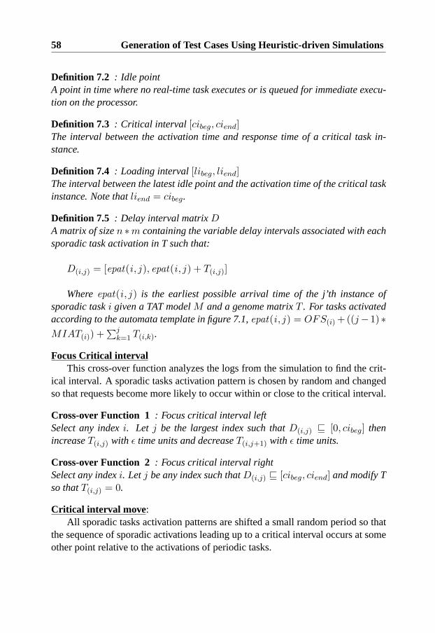
58 Generation of Test Cases Using Heuristic-driven Simulations
Definition 7.2 : Idle pointA point in time where no real-time task executes or is queued for immediate execu-tion on the processor.
Definition 7.3 : Critical interval [cibeg, ciend]The interval between the activation time and response time of a critical task in-stance.
Definition 7.4 : Loading interval[libeg, liend]The interval between the latest idle point and the activation time of the critical taskinstance. Note thatliend = cibeg.
Definition 7.5 : Delay interval matrixDA matrix of sizen ∗m containing the variable delay intervals associated with eachsporadic task activation in T such that:
D(i,j) = [epat(i , j ), epat(i , j ) + T(i,j)]
Whereepat(i , j ) is the earliest possible arrival time of the j’th instance ofsporadic taski given a TAT modelM and a genome matrixT . For tasks activatedaccording to the automata template in figure 7.1,epat(i , j ) = OFS(i) +((j− 1) ∗MIAT(i)) +
∑jk=1 T(i,k).
Focus Critical intervalThis cross-over function analyzes the logs from the simulation to find the crit-
ical interval. A sporadic tasks activation pattern is chosen by random and changedso that requests become more likely to occur within or close to the critical interval.
Cross-over Function 1 : Focus critical interval leftSelect any indexi. Let j be the largest index such thatD(i,j) v [0, cibeg] thenincreaseT(i,j) with ε time units and decreaseT(i,j+1) with ε time units.
Cross-over Function 2 : Focus critical interval rightSelect any indexi. Letj be any index such thatD(i,j) v [cibeg, ciend] and modify Tso thatT(i,j) = 0.
Critical interval move :All sporadic tasks activation patterns are shifted a small random period so that
the sequence of sporadic activations leading up to a critical interval occurs at someother point relative to the activations of periodic tasks.

7.3 Testing of Time Dependent Control Performance 59
Cross-over Function 3 : Critical interval move rightFor every indexi such thatD(i,1) v [0, cibeg] increaseT(i,1) with ε time units.
Cross-over Function 4 : Critical interval move leftFor every indexi such thatD(i,1) v [0, cibeg] decreaseT(i,1) with ε time units.
New interval focusThis cross-over function generates new candidate critical intervals to keep the
optimization from getting stuck in local optima. A new point in time is chosen byrandom and all the closest sporadic releases are shifted towards the selected pointin time.
Cross-over Function 5 : New interval focusLet tnew be a new random instant within the simulation interval. For every indexiselect the largest indexj such thatD(i,j) v [0, tnew] and increaseT(i,j) with ε timeunits. Also decreaseT(i,j+1) with ε time units.
Loading interval perturbation :Theoretically, all task activations in the loading interval may influence response
time through the state in the system when the request of the critical task instanceoccurs (Mellin 1998). In practice, it is more likely that changes at the end of theloading interval have a direct effect on the timeliness of the critical task instance.This cross-over function changes the activation pattern at the end of the loadinginterval.
Cross-over Function 6 : Loading interval perturbationSelect any indexi and a positive valueε. Let j be the the largest index such thatD(i,j) v [libeg, liend] andj > 1, modify T so thatT(i,j−1) = ε time units.
7.3 Testing of Time Dependent Control Performance
The only failure type considered in the previous examples and experiments is theviolation of time constraints, and in particular, response time deadlines. With aheuristic driven approach it is possible to use mutation-based testing to test morecomplex time constraints (for example, expressed using the constraint graph no-tation used by Berkenkotter & Kirner (2005)) and other properties that indirectlydepend on execution orders and temporal behavior of tasks.
60 Generation of Test Cases Using Heuristic-driven Simulations
Further, a real-time system simulator can be extended to take more aspects ofthe controlled system into consideration than those expressed in the real-time ap-plication model. In particular, by changing the set of variables being traced duringsimulation and by updating the fitness function and termination criteria, test casescan be generated that test new types of time constraints and time dependent prop-erties. One such property is control performance.
Many real-time systems have tasks that implement control applications. Suchapplications interact with physical processes through sensors and actuators to achievea control goal. For example, a painting robot may have a control application thatperiodically samples joint angles and sets different motor torques so that the robotmovement becomes smooth and aligned with the painted object.
Control algorithms contain built-in time constraints that are more subtle thanresponse time deadlines. The delay between sensor readings (typically done in thebeginning of task execution) and the actuator control (typically done at the end oftask execution) is known asinput-output latency. This includes the time passingwhile the task is preempted and blocked. Hence, this interval is different fromresponse times and execution times, as defined in section 2.2.
Excessive input-output latency compromises the performance of a control sys-tem, and may even cause instability. This means that an application may fail itscontrol goal causing acontrol failure to occur. Since the same types of errors thatcause timeliness failures may result in increased input-output latency (or a largerdifference between maximum and minimum input-output latency than expected),it is possible to use the mutation-based testing criteria presented in section 6.3 forthis purpose.
By co-simulating the real-time kernel execution with continuous process mod-els (for example, using Simulink) it is possible to measure the expected controlperformance for a particular execution order of tasks. This means that it is possibleto use mutation-based testing to automatically generate test cases that can stress areal-time control system to reveal control failures.
To support this type of test case generation, the closed-loop behavior of boththe controlled process and its controller logic (as implemented by real-time tasks)must be included in the simulation. Further, control specific variables must be usedfor calculating the fitness for the heuristic search problem.
In order to evaluate control performance it is common to use weighted quadraticcost functions (Astrom & Wittenmark 1997). For a scalar system, with one outputy and one inputu, the cost can be written

7.4 Test Case Generation Experiments 61
J =∫ Tsim
0
(y2(t) + ρu2(t)
)dt (1)
where the weight factor,ρ, expresses the relation between the two counteractingobjectives of control design(i) to keep the regulated output close to zero and(ii) tokeep the control effort small. The higher the cost measured during a simulation run,the worse the control performance. Therefore, we assume that1/J is proportionalto the control performance when calculating the fitness of a particular executionorder trace3.
The fitness of a simulation trace where both timeliness of hard tasks and controlperformance of soft, adaptive controllers should be considered can be defined as
F =∑
k
1Jk− Smin ∗ w (2)
whereSmin denotes the least slack observed for any hard real-time task. ThevariableJk denotes the value ofJ for adaptive controllerk at the end of the simula-tion. A weight variablew is used to adjust the minimum slack so that the timelinessfactor is of the same magnitude as the control quality factor.
Apart from calculating the general fitness that drives the genetic algorithmheuristics toward evaluating more fit solutions, the fitness function are also usedto detect failures and halt the search. Relevant failure conditions are that(i) a harddeadline is missed,(ii) the control system becomes unstable (the cost,J , exceedssome threshold value), or(iii) a control constraint is violated, for example, the mo-tion of a robot arm becomes too irregular. Failure condition(i) and(ii) can easilybe detected by checking the minimum slack of hard tasks and the value of the costfunction for the controller tasks. Failure condition(iii) is application-specific andmight require checking one or several process variables.
7.4 Test Case Generation Experiments
To evaluate the proposed test case generation method, three experiments were con-ducted. First, we establish basic confidence in the method by applying it to a sys-tem of the same type as used in the model-checking experiment. This allows us toevaluate the reliability of the proposed test case generation method in a base-lineexperiment and detect if it has difficulties to kill some types of malignant mutants.
3This way of measuring control fitness was developed together with Dan Henriksson for the ex-periment presented in Nilsson & Henriksson (2005)

62 Generation of Test Cases Using Heuristic-driven Simulations
Second, we test the hypothesis that the approach based on genetic algorithmscan remain effective for larger and more complex system models where the model-checking approach fails (because of the size of the reachable state space). In thisexperiment we automatically generate test cases from a real-time system modelwith a larger task set and a considerable fraction of sporadic tasks under complexreal-time system protocols.
Finally, we demonstrate the flexibility of the genetic algorithm based approachby using it for generating test cases for both timeliness and control performancefrom an extended real-time system model. In particular, this real-time systemmodel has a mixed load of soft and hard real-time tasks that share resources. Theperiodic tasks are soft and implement adaptive controllers for three inverted pendu-lums and the sporadic tasks are modelled to have hard deadlines.
To conduct the experiments, we extended the real-time and control co-simulationtool TrueTimeto simulate the execution of TAT-models (see section 8.3 for a de-scription of the added features). TrueTime was developed at the department ofautomatic control at the University of Lund to support the integrated design ofcontrollers and real-time schedulers (Henriksson, Cervin &Arzen 2003). We alsoconfigured and extended a genetic algorithm tool-box (Houck, Joines & Kay 1995)to interact with our simulated model. For model-checking experiments we used theTimestool, developed at Uppsala University (Amnell et al. 2002).
7.4.1 Base-line Real-time System
This experiment uses a small task set that has simple environment models but com-plex interactions between the tasks. Static priorities were assigned to the tasksusing thedeadline monotonicscheme, that is, the highest priority was given to thetask with the earliest relative deadline. Arbitrary preemption was allowed.
The system used theimmediate ceiling priorityprotocol to avoid priority inver-sion (Sha, Rajkumar & Lehczky 1990). That is, if a task locks a semaphore thenits priority becomes equal to the priority of the highest priority task that might usethat semaphore, and is always scheduled before lower prioritized tasks. The “firstcome first served” policy is used if several tasks have the same priority.
The base-line setup has five tasks (denoted A-D, and listed in table 7.1). Twotasks are sporadic and the three remaining tasks are strictly periodic. The systemhas two shared resources and one precedence relation between tasks D and A. Theprecedence relation specifies that a new instance of task A cannot start unless taskD has executed after the last instance of A.
Table 7.1 describes the assumptions of the task set. The first column (“ID”)

7.4 Test Case Generation Experiments 63
ID c d SEM PREC MIAT OFS
A 3 7 {(S1, 0, 2)} {D} ≥ 28 10B 5 13 {(S1, 0, 4), (S2, 0, 5)} {} ≥ 30 18C 7 17 {(S1, 2, 6), (S2, 0, 4)} {} 40 6D 7 29 {} {} 20 0E 3 48 {(S1, 0, 3), (S2, 0, 3)} {} 40 4
Table 7.1: Task set for base-line experiment
indicates task identifiers, column ‘c’ gives execution times, and column ‘d’ pro-vides relative deadlines. The “SEM” column specifies the set of semaphores usedand in which interval they are required. Column “PREC” reveals what other taskshave precedence over tasks of this type. For sporadic tasks, the “MIAT” columncontains the minimum inter-arrival time assumptions. For periodic tasks the samecolumn contains the fixed inter-arrival time. Column “OFS” denotes the initialoffset constant.
Table 7.2 contains the results from mutation testing the task set in table 7.1. A∆ value of 1 time unit was used to generate the mutants. The number of mutantsgenerated for each operator type is listed in column ‘µ’ and the number of mutantskilled by model-checking is contained in column “KMC”. For the genetic algo-rithm setup, we used a population of 20 individuals per generation and searchedeach mutant for 100 generations before terminating. We used the heuristic cross-over functions described in section 7.2.3 as well as three generic cross-over func-tions. The first generic cross-over function changed a random value in the genomerepresentation, the second created a new random individual in the population andthe third replaced a random value in the genome with 0. To gain confidence in theresults, each experiment was repeated in eight trials, each with a different randomseed. The number of mutants killed using genetic algorithms in any of the trialsis listed in column “KGA”. Column “KGA” lists the average number of malignantmutants that were killed per trial. The average number of generations required tokill malignant mutants of this type is contained in column “GEN ”.
As revealed in table 7.2, both the simulation-based and model-checking ap-proaches killed all the malignant mutants. Strangely, the model-checking approachalso killed some mutants that was benign using the simulator implementation. Bycomparing the execution orders of the benign mutants that were killed, we observedthat tasks sometimes inherited ceiling priorities before they started executing in thetraces produced by the model-checker. The number of mutants that where found
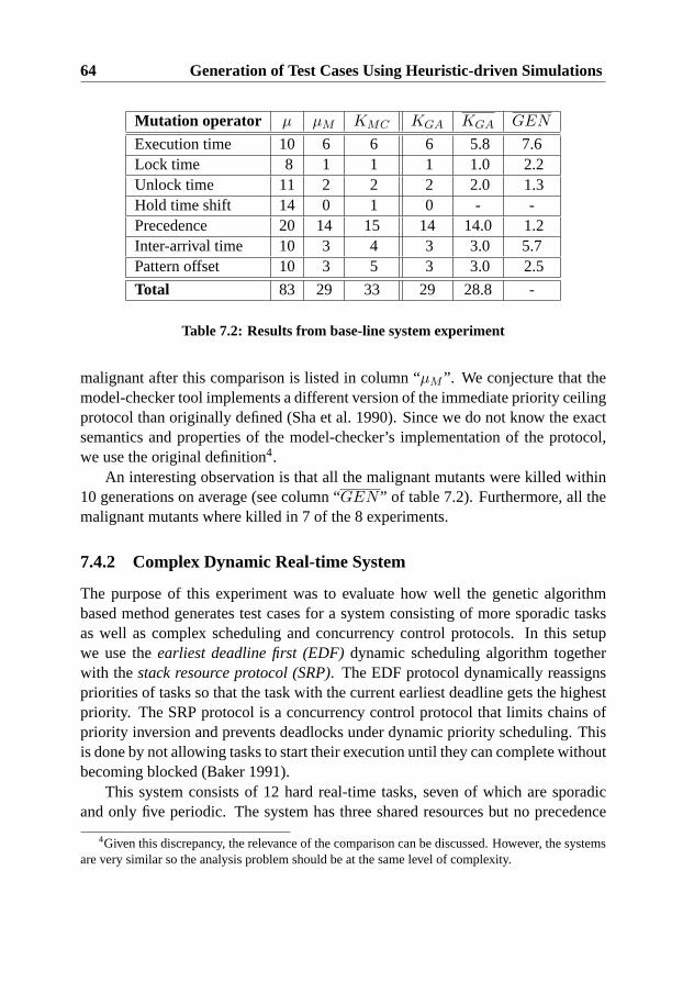
64 Generation of Test Cases Using Heuristic-driven Simulations
Mutation operator µ µM KMC KGA KGA GEN
Execution time 10 6 6 6 5.8 7.6Lock time 8 1 1 1 1.0 2.2Unlock time 11 2 2 2 2.0 1.3Hold time shift 14 0 1 0 - -Precedence 20 14 15 14 14.0 1.2Inter-arrival time 10 3 4 3 3.0 5.7Pattern offset 10 3 5 3 3.0 2.5
Total 83 29 33 29 28.8 -
Table 7.2: Results from base-line system experiment
malignant after this comparison is listed in column “µM ”. We conjecture that themodel-checker tool implements a different version of the immediate priority ceilingprotocol than originally defined (Sha et al. 1990). Since we do not know the exactsemantics and properties of the model-checker’s implementation of the protocol,we use the original definition4.
An interesting observation is that all the malignant mutants were killed within10 generations on average (see column “GEN ” of table 7.2). Furthermore, all themalignant mutants where killed in 7 of the 8 experiments.
7.4.2 Complex Dynamic Real-time System
The purpose of this experiment was to evaluate how well the genetic algorithmbased method generates test cases for a system consisting of more sporadic tasksas well as complex scheduling and concurrency control protocols. In this setupwe use theearliest deadline first (EDF)dynamic scheduling algorithm togetherwith thestack resource protocol (SRP). The EDF protocol dynamically reassignspriorities of tasks so that the task with the current earliest deadline gets the highestpriority. The SRP protocol is a concurrency control protocol that limits chains ofpriority inversion and prevents deadlocks under dynamic priority scheduling. Thisis done by not allowing tasks to start their execution until they can complete withoutbecoming blocked (Baker 1991).
This system consists of 12 hard real-time tasks, seven of which are sporadicand only five periodic. The system has three shared resources but no precedence
4Given this discrepancy, the relevance of the comparison can be discussed. However, the systemsare very similar so the analysis problem should be at the same level of complexity.

7.4 Test Case Generation Experiments 65
ID c d SEM PREC MIAT OFS
A 3 20 {(S1,0,2), (S2,0,2)} {} ≥ 28 10B 4 24 {(S1,0,3)} {} ≥ 30 4C 5 35 { (S2,2,5)} {} ≥ 38 6D 6 57 {(S2,0,6), (S3,2,5)} {} ≥ 48 0E 5 51 {} {} ≥ 52 7F 6 39 {(S3,3,6)} {} ≥ 44 0G 3 52 {} {} ≥ 52 2H 3 38 {(S3,0,2)} {} 40 5I 3 35 {(S1,1,2)} {} 48 2J 4 52 {} {} 60 2K 2 70 {(S2,0,2)} {} 80 10L 3 59 {} {} 60 12
Table 7.3: Task set for complex real-time system
constraints. The complete task characteristics are listed in table 7.3, using the samenotation as in table 7.1.
For this system we found it to be very time consuming and complicated to man-ually derive the number of malignant mutants. Moreover, model-checking cannotbe used for comparison since the reachable state-space becomes too large5. Sincewe could not find an alternative way to efficiently and reliably analyze mutants, wecannot guarantee that the method killed all the malignant mutants.
To increase confidence in the correctness of the original specification model,every generated test case was also run on the original (un-mutated) TAT specifi-cation. In a previous iteration of experiments, this kind of test actually revealed afault in a specification that was assumed to be correct.
For this experiment, we used a delta size of two time units for the mutationsof the execution patterns, and a delta size of six time units on the mutations on au-tomata template constants. We ran the genetic algorithm and searched each mutantfor 200 generations or until a failure was encountered. Each experiment was per-formed in five trials with different inial random seeds to guard against stochasticvariance. For each simulation performed during the heuristic search, a random testwas also conducted. This provides an indication of the relative efficiency between
5The Times tool does not currently support the SRP protocol and a sporadic task set of this sizewas refused by the model-checker (the analysis was terminated when no more memory could beallocated).

66 Generation of Test Cases Using Heuristic-driven Simulations
Mutation operator µ KR KGG KGA KGA GEN
Execution time 24 0 0 12 9.2 62Unlock time 16 0 0 0 - -Inter-arrival time 24 0 0 8 3.8 90Offset time 22 0 0 0 - -
Total 86 0 0 20 13.0 -
Table 7.4: Results from complex system experiment
random search and genetic algorithms with our heuristic. Furthermore, we ran agenetic algorithm experiment using only the three generic cross-over functions, de-scribed in section 7.4.1, to assess the added performance of our heuristics.
Since every mutant operator generated more mutants for this system model wedecided to use a subset of mutation operator types. Table 7.4 uses the same columnnotation as table 7.2, but the additional columns “KR” and “KGG” include theresults from random testing and non-customized genetic algorithms respectively.
As table 7.4 indicates, no malignant unlock time or offset time mutants werefound for this particular system. The average number of generations required tokill a mutant was higher for this system specification model, which indicates thatthe search problem is much more difficult than for the more static system presentedin section 7.4.1.
The low average number of mutants killed in each experiment suggests thatthe genetic algorithms may have to run longer on each mutant to achieve reliableresults. A possible explanation for this is that the genetic algorithm has troublefinding comparable candidates without the iterative refinement from the heuristicoperators. Hence, it would often prematurely discard partially refined candidates.
A possible remedy for these problems is to redo the search multiple times usinga fresh initial population. Since searching the mutant models is a fully automatedprocess, the additional cost of multiple searches may be acceptable. If no newmutants are killed after a specified number of searches, the process can be halted.
The comparison with random testing and generic genetic algorithms shows thatthe heuristic cross-over functions are vital for the performance of the method.
7.4.3 Mixed Load Real-time Control System
The purpose of this experiment was to investigate if a mutation-based testing tech-nique can generate test cases to reveal timeliness in flexible control systems wherethere is a mixed load of soft, adaptive controllers and reactive real-time tasks with
7.4 Test Case Generation Experiments 67
hard deadlines. To evaluate the control performance testing, described in section7.3, test cases which target execution orders that result in unacceptable controlperformance are also generated. Hence, this experiment evaluates whether the mu-tation operators can create malignant mutants in this kind of system as well as howeffective our genetic algorithm based approach is in killing such mutants.
For this experiment, we simulated a real-time system with fixed priorities andshared resources under the immediate priority ceiling protocol (Sha et al. 1990).The task set consists of three soft periodic tasks that implement flexible controllersfor balancing three inverted pendulums. The linearized equations of the pendulumsare given as
θ = ω20θ + ω2
0u (3)
whereθ denotes the pendulum angle andu is the control signal.ω0 is the naturalfrequency of the pendulum. The controllers were designed using LQ-theory withthe objective of minimizing the cost function6
J =∫ (
θ2(t) + 0.002u2(t))
dt. (4)
Further, the system has four sporadic real-time tasks with hard deadlines, as-sumed to implement logic for responding to frequent but irregular events, for ex-ample, external interrupts or network messages. The system also includes tworesources that must be shared with mutual exclusion between tasks.
Table 7.5 lists the exact properties of the simulated task set using the samenotation as in the previous experiments.
Three continuous-time blocks, modelling the inverted pendulums, was includedin the simulation and connected in a feedback loop to the TrueTime block that sim-ulated the flexible control system. Each of the modelled pendulums have a slightlydifferent natural frequency,ω0, and the goal of the control application was to bal-ance the pendulums to an upright position. The pendulums had an initial angle of0.1 radians from the upright position when the simulation started. An application-specific control failure was assumed to occur when the angle of a pendulum becamegreater than or equal toπ/8 (∼ 0.39) radians.
A set of mutants was generated by applying the mutation operators describedin section 6.3 on the extended task set in Table 7.5 using a∆ of two time unitsfor the first three mutation operator types and four time units for the last two. The
6The controller design for the inverted pendulums was provided by Dan Henriksson (Nilsson &Henriksson 2005).

68 Generation of Test Cases Using Heuristic-driven Simulations
ID c d SEM PREC MIAT OFS
A 3 7 {(R2, 0, 2)} {} ≥ 30 10B 5 15 {(R1, 0 , 3), (R2, 2, 5)} {} ≥ 40 20C 4 20 {(R1, 0, 3)} {} ≥ 40 0D 5 26 {(R2, 2, 5)} {} ≥ 50 28E 5 20 {(R1, 4, 5)} {} 20 1F 5 29 { (R2, 0, 4)} {} 29 1G 5 35 { (R1, 0, 3)} {} 35 1
Table 7.5: Case study task set
total number of mutants generated for each operator type is listed in column ’µ’ oftable 7.6.
For the genetic algorithm setup, we used a population size of 25 activation pat-tern matrices. The heuristic cross-over functions as presented in section 7.2.3 wereused for stochastically changing activation patterns. The fitness function defined insection 7.3 was used when analyzing the simulation traces.
First, the unmodified system was simulated for200 generations to gain con-fidence in the assumed correct specification. This was repeated five times withdifferent random seeds to protect against stochastic variance. No failures were de-tected in the original model.
Second, each mutant was searched for100 generations or until a timelinessor control failure was detected. When a mutant was killed, the same activationpattern was used as input for a simulation of the assumed correct system model.The motivation for this extra step was to further increase confidence in the safetyof the original model.
The experiment was repeated in five trials to assess the reliability of the ap-proach. Table 7.6 summarizes the results for each mutation operator and failuretype using the same notation as in table 7.2.
As indicated in table 7.6, our mutation-based approach using the Flextime toolautomatically generates test cases for revealing both timeliness and control failures.In addition, the malignant mutants that cause timeliness failures were killed in allof the experiments. This result increases confidence in the genetic algorithm beingeffective in revealing critical execution orders with respect to timeliness in modelsof mixed load control systems of this size. The relatively low average of killed mu-tants causing control failures indicates that finding a critical scenario with respect tocontrol is difficult. A possible explanation is that the optimization problem contains
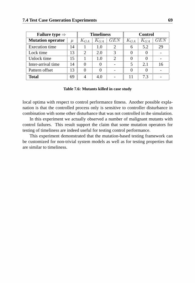
7.4 Test Case Generation Experiments 69
Failure type ⇒ Timeliness ControlMutation operator µ KGA KGA GEN KGA KGA GEN
Execution time 14 1 1.0 2 6 5.2 29Lock time 13 2 2.0 3 0 0 -Unlock time 15 1 1.0 2 0 0 -Inter-arrival time 14 0 0 - 5 2.1 16Pattern offset 13 0 0 - 0 0 -
Total 69 4 4.0 - 11 7.3 -
Table 7.6: Mutants killed in case study
local optima with respect to control performance fitness. Another possible expla-nation is that the controlled process only is sensitive to controller disturbance incombination with some other disturbance that was not controlled in the simulation.
In this experiment we actually observed a number of malignant mutants withcontrol failures. This result support the claim that some mutation operators fortesting of timeliness are indeed useful for testing control performance.
This experiment demonstrated that the mutation-based testing framework canbe customized for non-trivial system models as well as for testing properties thatare similar to timeliness.

70 Generation of Test Cases Using Heuristic-driven Simulations

EPISODE III
Empiricism strikes back
71


Chapter 8
T 3: A Tool for Mutation-basedTesting of Timeliness
This chapter describes different parts of a prototype tool that support the frameworkfor mutation-based testing and implements the heuristic driven simulation approachfor test case generation described in chapter 7.
8.1 Overview
The Timeliness Testing Tool (T 3) consists of the real-time simulator extensionsprovided by the Flextime add-on, as well as implementations of the defined muta-tion operators, parametrization of the genetic algorithm, and the scripts that auto-mate the test case generation process.
Figure 8.1 provides an overview of how the different parts of this prototypetool are used to perform automated test case generation. As the figure indicates, areal-time system model and a testing criterion must be supplied as input to the tool(arrow 1a and 1b in figure 8.1). In the current prototype, the real-time applicationmodel must be manually translated to a native tabular format. However, this in-formation could be retrieved from an existing TAT modelling tool (such as Times(Amnell et al. 2002)) or a graphical user interface. The execution environmentmodel can be modified by configuring the simulator using the Flextime add-on.
The mutation operators corresponding to the given testing criterion create a setof mutant models. These operators have been implemented to operate on the tabularrepresentation of real-time application models. For each generated mutant in theset, the corresponding model is given as input to the Flextime simulator add-on
73

74 T 3: A Tool for Mutation-based Testing of Timeliness
MATLAB Simulink
Truetime +Flextime
2) Mutated model
3) Activation patternAdaptedGeneticAlgorithm
Mutation operators
4) Simulation trace5) Test suite
1b) TAT-model
1a) Testing criterion
Figure 8.1: Test case generation tool
running on Simulink and TrueTime (arrow 2 in figure 8.1).
A genetic algorithm search is then initiated for each mutant. First, a populationof activation patterns is randomly generated by the adapted genetic algorithm andsupplied one by one to the simulator (arrow 3 in figure 8.1). For each simulation,a trace is returned to the genetic algorithm (arrow 4 in figure 8.1) so that fitnesscan be calculated and the activation patterns refined according to heuristics. Thenew activation patterns are fed back to the simulator (arrow 3 in figure 8.1) and theprocess is repeated until the mutant is killed or the search is terminated. After eachmutant has been searched for violated time constraints, a test suite is generatedcontaining one test case for each of the killed mutants (arrow 4 in figure 8.1).
8.2 Flextime Simulator Extensions
Flextime is an add-on to the real-time control systems simulator TrueTime (Henrikssonet al. 2003). The purpose of the Flextime add-on is primarily to support automatedanalysis and mutation-based test case generation. For this purpose TrueTime mustbe adapted to(i) do efficient simulation ofTATsystem models,(ii) support struc-tured parametrization of simulations, and(iii) simplify extensions that are consis-tent withTATspecifications.
When Flextime is used for mutation-based test case generation a mutantTATmodel should be mapped to simulation entities. The following subsections describethe TrueTime tool and howTAT task sets and activation patterns are mapped tosimulations by the Flextime extension.
8.2 Flextime Simulator Extensions 75
8.2.1 TrueTime
TrueTime is an open source real-time kernel simulator based on MATLAB/Simulink(Henriksson et al. 2003). The main feature of the simulator is that it offers thepossibility of co-simulation of task execution in a real-time kernel and continuousdynamics modelling. The simulator is mainly used for the integrated design of con-trollers and schedulers, and can be used to analyze the effects of timeliness errorson the control performance of such systems.
The TrueTime kernel support the simulation of periodic and aperiodic tasks,and the attributes of the tasks (such as periods and deadlines) may be changeddynamically during simulation. The scheduling algorithm used by the kernel isconfigurable and can be defined by the user. Synchronization between tasks issupported by events and the protection of shared resources is simulated as mutualexclusive monitors1.
Each task in TrueTime is implemented in a separate code function that definesthe execution behavior. The code function includes everything from interactionwith resources, I/O ports and networks to the specification of execution time ofdifferent segments. The TrueTime code functions may be written as either C++functions or as MATLAB scripts (called m-files).
8.2.2 Task Sets and Execution Patterns
For automated analysis and mutation-based test case generation, we find it usefulto distinguish between application functionality and execution behavior. Therefore,in the Flextime extension, execution times, resource requirements, and precedenceconstraints are specified separately from code functions. This design makes it pos-sible to specify execution patterns of large task sets without having to generatea specific code function for each type. The role of code functions in Flextimeis specialized to perform control related calculations and to interact with externalSimulink blocks.
Figure 8.2 shows a subset of the class diagram for Flextime. The classftTaskis an abstract class that maps down to the TrueTime tasks. This means that whenobjects of any of the sub-classes to this class are created, a TrueTime task is alsocreated and initialized. The abstractftTaskclass contains basic information abouttasks, such as periods, deadlines and offsets. Moreover, theftTaskclass extendsTrueTime tasks with a list of execution items that define the execution pattern foreach instance of this task.
1These primitives can be used to implement other, more complex, synchronization mechanisms.

76 T 3: A Tool for Mutation-based Testing of Timeliness
ftTask
FP_IPC_Task
executionItem
executeWork takeRes releaseRes
-{ordered}
1 *
ftResource
IPC_Resource
Figure 8.2: Flextime classes
The sub-classes offtTaskandftResourceare primarily used for supporting dif-ferent concurrency control protocols, but other types of execution environment ex-tensions are also supported. For example, one pair of subclasses can be used tosimulate tasks and resources under the immediate priority ceiling protocol (Shaet al. 1990), whereas another pair may be used for simulation of tasks under EDFscheduling and the stack resource protocol (Baker 1991). The reason sub-classesare needed for both types of entities is that such protocols often require specificdata to be kept with task and resource representatives.
When anftTaskbegins its execution, a virtualdo segmethod is called sequen-tially on each item in the execution item list. Execution items of typetakeResandreleaseResspecify that a particular resource is to be locked or unlocked. Thedo segfunction in these execution items simply invokes a corresponding virtualtakeandreleasefunction in theftTaskclass with the resource identifier as a parameter. Inthis way, the logic associated with acquiring and releasing resources can be imple-mented in the protocol-specific sub-classes offtTask, and execution item classesremain protocol independent. Execution items of the typeexecuteWorkare genericand specify that execution of code should be simulated for some duration, and op-tionally, that a segment of a Flextime code function should be executed. All theaforementioned objects can be created using the factory method pattern to supportextendability and configuration (Gamma, Helm, Johnson & Vlissides 1994).
In the Flextime tool, task sets can be initialized in two different ways. Oneis to create the Flextime tasks and populate execution item lists statically in theTrueTime initialization code function. Figure 8.3 includes an example2 of the C++
2For simplicity, the task and execution pattern instances are explicitly constructed without thefactory method pattern in this example.

8.2 Flextime Simulator Extensions 77
void init(){// String IDstatic IPC_Resource R1("State_Sem");
// TYPE, StringID, Priority , MIAT, OFS, Deadlinestatic FP_IPC_Task A(SPOR,"Safety_check", 1 , 0.040,0.0,0.020);A << 0.001 <<+R1<< 0.005 << -R1 << 0.002 << FINISHED;
static FP_IPC_Task B(PER,"Pendulum", 2 , 0.040, 0.020, 0.040);B << 0.002 << +R1 << 0.006 << -R1 << 0.001 << FINISHED;
}
Figure 8.3: C++ Syntax for initializing task set
// Specify task and resource sub-typesRFactory<IPC_Resource> RCreator;TFactory<FP_IC_Task> TCreator;
void init(){
// Import task set from MATLAB variables TS and XPTasksetImporter TSI("TS","XP");TSI.importRes(RCreator);TSI.importTasks(TCreator);TSI.importPrecs();
}
Figure 8.4: C++ Syntax for importing task set
syntax required for initializing a task set. The second way, which is assumed ifno specific C++ initialization file is given, is that the task set specification for asimulation is provided through matrices in the global MATLAB workspace. Seefigure 8.4 for an example setup in which a task set is imported.
The matrix representation of task sets has the advantage that different mutationoperators directly can be applied to create new mutants. However, if new tasktypes, concurrency control mechanisms or scheduling protocols are used, then theC++ initialization file must be customized accordingly.
New tasks types may have additional constraints on activation patterns cor-responding to timed automata models. For such task types, a C++ method that

78 T 3: A Tool for Mutation-based Testing of Timeliness
performs the mapping from the genome representation to a valid activation patternmust be implemented, this is further discussed in section 10.2.2.
8.2.3 Activation Patterns
As previously described in section 7.2.1, the activation patterns from periodic tasksare deterministic and can be initialized as usual with the TrueTime kernel block.The activation pattern for sporadic tasks should be varied for each simulation tofind execution orders that can lead to timeliness failures. Consequently, a newactivation pattern for the sporadic tasks must be imported for each simulation run.The FlexTime tool is capable of importing activation patterns in the genome formatdescribed in section 7.2.1 or as a matrix with absolute activation times for each taskinstance. In particular, activation pattern matrices of this type are also importedfrom the global MATLAB workspace at the start of each simulation run.
Traces from each simulation run are stored and exported to MATLAB after thesimulation run has ended. For example, task activation times, start times3 as well asresponse times are stored from each simulation. In the global MATLAB workspace,these simulation logs can be visualized, analyzed, filtered and converted to timeli-ness test cases (see section 5.2).
8.3 Test Case Generation Support
This section presents some different ways that the prototype tool can be used tosupport modelling and test case generation.
8.3.1 Modes for Generating Test Cases
The prototype tool currently support two different modes for generating and ana-lyzing mutant models, fixed delta mode and iterative delta reduction mode.
In the fixed delta mode, a mutation operator is invoked with a specified deltavalue and mutants are created by changing some aspect of the original specificationwith a constant value, delta. The heuristic search is run on each of the mutatedmodels and if a deadline violation is detected, a test case is generated and the searchis terminated.
In the iterative delta reduction mode, a maximum delta is specified togetherwith the mutation operator. This mode is a feature that supports generation of
3These are the points in time when tasks actually start executing in response to activations
8.3 Test Case Generation Support 79
test suites with different delta parameters rather than an extension to the theory ofmutation-based testing of timeliness. Recalling the framework overview figure 5.1this supports an automated feedback loop from activity 3 to activity 1.
In this mode, the tool starts by applying the mutation operator using the maxi-mum delta on the original real-time system model to create a set of mutants. Thisstep is similar to the fixed delta generation mode. If a deadline violation is foundin a mutant, then delta is decreased with one time unit and all the individuals inthe test population are re-evaluated using the new model. A new heuristic searchis started on the new mutant using the end population of the previous search as aninitial population. This process is iterated until no deadline violation is found ordelta has been decreased to zero.
If the maximum delta is set high it is likely that the maximum number of testcases is produced for each mutation operator. As the delta is decreased it becomesharder to kill the malignant mutants, since the difference between the mutants andthe feasible model becomes smaller. Using the iterative delta reduction mode, theuser does not need to manually try different delta sizes before deciding which onewould give the best trade-off between test quality and test suite size. Instead, whenthe test case generation terminates the user may choose between generated testsuites for different sizes of the parameter delta. It is also possible to create a testsuite containing only the test cases that can kill the smallest mutation of a partic-ular entity. For example, one of the test cases might kill all∆− interarrival timemutations of task A where∆ > 2 milliseconds, whereas another test case in thesame test-suite may kill all∆− interarrival time mutations of task B where∆ > 5milliseconds. Figure 8.5 shows the pseudo code for the iterative delta reductionmode where only one test case for each mutated entity is included in a test suite.
The effectiveness of this mode relies on the hypothesis that there is a subsump-tion relation between mutants of the same type but with different delta sizes. Thismeans that a test case generated using a smaller delta should be effective for killingall mutants of the same entity with larger deltas. Since such subsumption relationdoes not holds for all system designs (for example, see section 6.6), the tool sup-ports an extra validation step where the final test case is simulated on all previouslykilled mutants with larger delta sizes. If a mutant that is generated using a largedelta cannot be killed using that test case, then the anomaly is logged and both testcases are stored.
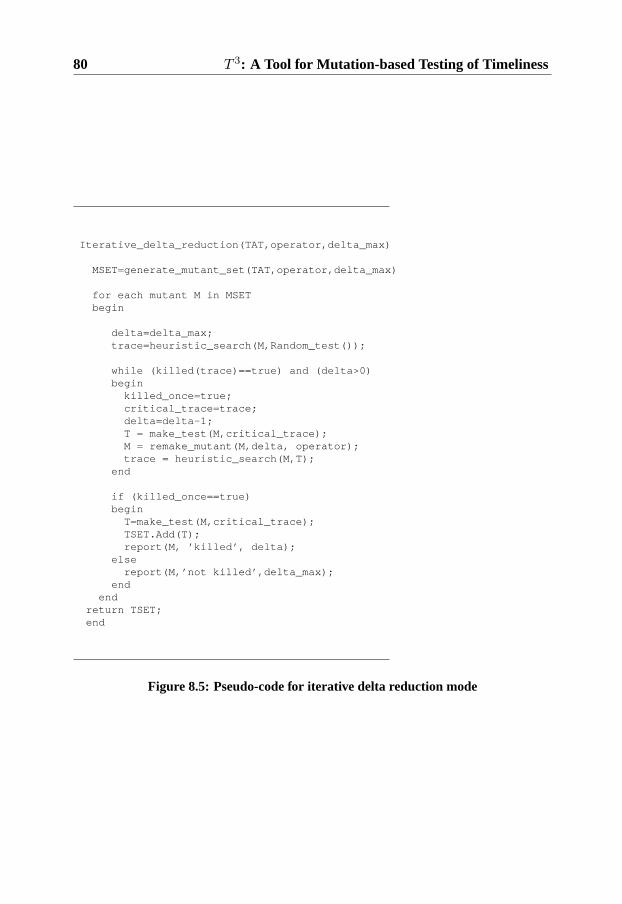
80 T 3: A Tool for Mutation-based Testing of Timeliness
Iterative_delta_reduction(TAT,operator,delta_max)
MSET=generate_mutant_set(TAT,operator,delta_max)
for each mutant M in MSETbegin
delta=delta_max;trace=heuristic_search(M,Random_test());
while (killed(trace)==true) and (delta>0)begin
killed_once=true;critical_trace=trace;delta=delta-1;T = make_test(M,critical_trace);M = remake_mutant(M,delta, operator);trace = heuristic_search(M,T);
end
if (killed_once==true)begin
T=make_test(M,critical_trace);TSET.Add(T);report(M, ’killed’, delta);
elsereport(M,’not killed’,delta_max);
endend
return TSET;end
Figure 8.5: Pseudo-code for iterative delta reduction mode
8.3 Test Case Generation Support 81
8.3.2 Support for Task Instance Modelling
The Flextime add-on and the mutant generator programs that implement the mu-tation operators also support an extended form of task modelling that enables aunique task execution pattern to be associated with each task instance.
This addition does not require an extension of the TAT notation since it canbe modelled as a TAT automata template that releases one different task for eachstimuli in an activation pattern. If task mutation operators are applied on systemsmodelled in this way, each task instance may be mutated independently. However,to maintain the semantics of the mutation operators and to keep the number ofmutants bounded by the maximum in table 8.2, all execution patterns of a particulartask must be mutated in the same way.
The advantage with this extension is that deterministic variations in task execu-tion patterns can be modelled in a simple way. For example, if we know that everythird release of a particular task always executes longer or locks a different set ofresources, the behavior of that task can be modelled as a chain of task executionpatterns instead of one static task execution pattern. An example illustrating theusefulness of this modelling style is presented in section 9.4.1.
To keep the simulation deterministic with respect to activation pattern, eachexecution pattern for a particular task must be statically ordered so that the n’thactivation of task A always has the same execution pattern. A possible future ex-tension would be to associate each task type with a “bag” of possible execution pat-terns (behaviors) and let the heuristic search algorithm dynamically decide whichshould be used for a particular task activation. However, this kind of extensionwould further increase the domain of the search problem (see section 10.2.1).

82 T 3: A Tool for Mutation-based Testing of Timeliness

Chapter 9
Case Study: Testing using theMutation-based Framework
This chapter demonstrates how the framework described in chapter 5 can be appliedfor testing of timeliness and presents some experiments that evaluate the generatedtest cases.
9.1 Overview
The purpose of this case study is to assess the applicability of the approach formutation-based testing presented in chapter 5 (and the associated tool, presented inchapter 8) for the automated testing of timeliness.
This case-study can be classified as acontrolled case-study, which means thatan idea is used in a limited situation with realistic assumptions. This does notnecessarily generalize to a broad range of cases, but can give indications that theidea is useful. The idea in this context is using the mutation-based frameworkto test timeliness. In particular, the proposed framework is used to test a smallcontrol application running on an open source real-time operating system. Theconfiguration of the target system and the real-time system model is changed overa set of experiments to identify under which conditions the framework is useful.
The effectiveness of test cases generated using the mutation-based testing frame-work is compared with timeliness test cases generated using random testing. Ifthe applied framework is more effective than random testing for finding timelinessfaults, confidence is increased in the feasibility of the approach (also see the thesisstatement in section 4.4.1). Further, application on a realistic system platform may
83
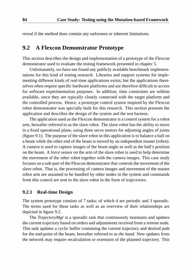
84 Case Study: Testing using the Mutation-based Framework
reveal if the method does contain any unforseen or inherent limitations.
9.2 A Flexcon Demonstrator Prototype
This section describes the design and implementation of a prototype of the Flexcondemonstrator used to evaluate the testing framework presented in chapter 5.
Unfortunately, we have not found any publicly available benchmark implemen-tations for this kind of testing research. Libraries and support systems for imple-menting different kinds of real-time applications exists; but the applications them-selves often require specific hardware platforms and are therefore difficult to accessfor software experimentation purposes. In addition, time constraints are seldomavailable, since they are typically closely connected with the target platform andthe controlled process. Hence, a prototype control system inspired by the Flexconrobot demonstrator was specially built for this research. This section presents theapplication and describes the design of the system and the test harness.
The application used as the Flexcon demonstrator is a control system for a robotarm, hereafter referred to as the slave robot. The slave robot has the ability to movein a fixed operational plane, using three servo motors for adjusting angles of joints(figure 9.1). The purpose of the slave robot in this application is to balance a ball ona beam while the other end of the beam is moved by an independent master (robot).A camera is used to capture images of the beam angle as well as the ball’s positionon the beam. A force sensor on the arm of the slave robot is used to help determinethe movement of the other robot together with the camera images. This case studyfocuses on a sub-part of the Flexcon demonstrator that controls the movement of theslave robot. That is, the processing of camera images and movement of the masterrobot arm are assumed to be handled by other nodes in the system and commandsfrom this control are sent to the slave robot in the form of trajectories.
9.2.1 Real-time Design
The system prototype consists of 7 tasks; of which 4 are periodic and 3 sporadic.The terms used for these tasks as well as an overview of their relationships aredepicted in figure 9.2.
TheTrajectoryMgris a sporadic task that continuously maintains and updatesthe current trajectory based on orders and adjustments received from a remote node.This task updates a cyclic buffer containing the current trajectory and desired pathfor the end-point of the beam, hereafter referred to asthe hand. New updates fromthe network may require recalculation or extension of the planned trajectory. This

9.2 A Flexcon Demonstrator Prototype 85
JOINT 1
JOINT 2
JOINT 3FORCE SENSOR
MASTER ROBOTRUBBER
JOINT
BALL
Figure 9.1: Robot demonstrator overview
Joint Motor 1
Angle sensor 1
Force Sensor
Joint Motor 2
Angle sensor 2
Joint Motor 3
Angle sensor 3
Controller 1
Controller 3
Controller 2
RTAI Real-time nodeNetwork/user-space
Trajectorymanager
Ref. adjuster
Force handler
Task
Task
Task
Task
TaskTask
Watch-dog
Task
Robot hardware
Figure 9.2: Tasks and their relation to each other

86 Case Study: Testing using the Mutation-based Framework
task also translates trajectory coordinates in the form〈x, y, angle〉 to the corre-sponding set points for the three joints. Herex andy are the position of the handrelative to the base point of the robot arm;angle is the desired angle of the hand,relative to the ground.
TheRefAdjustertask is coordinating the controllers by adjusting the referencesignal (set-points) to follow the precalculated trajectory. This sporadic task is ac-tivated when the robot arm is within the bounds of certain intermediate via-pointsalong the trajectory.
In this prototype, the robot arm is assumed to be equipped with a sub-systemthat sends interrupts when the force applied to the robot hand is changed. Theinterrupts from the force sensor are serviced by the sporadicForceHandlertaskthat filters the information and sends notifications to a remote node if changes areabove a certain threshold.
Three tasks (Controller 1, 2 and 3) are periodic controllers with a relatively highsampling rate for accurately controlling the joints of the robot. These controllersget feedback through angle sensors that are read at the beginning of each task exe-cution. The implementation of controllers are of PID-type, configured according tothe dynamics of the controlled system. The three controller tasks are implementedusing a single thread similar to a cyclic executive (c.f., Burns & Wellings (2001)).This means that the periods of the controllers harmonize and that the relative activa-tion order of these periodic tasks is known. This implementation style is advocatedby Klas Nilsson, the domain expert within the Flexcon project (Nilsson 2005). Fortest case generation purposes this thread can be modelled as a shared mutual exclu-sive resource between the controller tasks.
A high priority Watch-dogtask is used to ensure that the hardware is alwaysserviced within a certain interval of time. The reason for this is that the robothardware requires the hardware interface to be polled with a certain minimum rate(Nilsson 2005). To monitor the polling, a shared time stamp structure is updatedevery time any task polls the hardware interface. If the watchdog detects that thehardware has not been polled within the interval then actions are taken to service theinterface. Furthermore, the watchdog task is responsible for checking the integrityof the control system and regularly sends messages to remote nodes indicating thatthe controllers are up and running.
This design of the robot control prototype has four resources that require mutualexclusive access, which are listed in table 9.1. Table 9.2 summarizes the applica-tion task set and lists the various shared resources used by the different tasks. Foran application such as a robot arm controller, there is a trade-off between controlperformance and the periods (sampling frequency), hence, it is the designer who

9.2 A Flexcon Demonstrator Prototype 87
Semaphore Protected resourceQ HW interface + TimestampsR Current setpointS Trajectory buffer + indicesT Network interface
Table 9.1: Shared system resources
Task ResourcesTrajectoryMgr S TRefAdjuster R S
ForceHandler Q TController 1 Q RController 2 Q RController 3 Q RWatch-dog Q T
Table 9.2: Task set of prototype with shared resources
sets suitable periods. In other applications involving the Flexcon robots, the sam-pling frequency of the joint controllers varies between 200 Hz (which is the lowerlimit from the closed-loop dynamics of the system) up to 4 KHz to improve thedisturbance rejection of the system (Henriksson 2006). This prototype is designedfor a sampling frequency at 2.5 KHz, to get disturbance rejection while not notoverloading the system.
For sporadic tasks, the offsets, periods and timing constraints are typically de-cided by properties of the environment, network protocols, or set by system de-signers to meet end-to-end deadlines in distributed real-time applications. For thetesting experiments in this chapter, the attributes of sporadic tasks are chosen sothat the system remains timely in worst-case situations without wasting resources.Hence, these attributes can be altered during experimentation. The reason for thisexperiment design is that it is easier to change the deadlines and periods rather thanthe system implementation or properties of the platform.
9.2.2 Target Platform
The target system for this application is a x86 based pc (a 450 MHz Pentium III)running Linux with RTAI (Real-Time Applications Interface). The operating sys-tem Linux/RTAI (Bianchi, Dozio, Ghiringhelli & Mantegazza 1999) has several
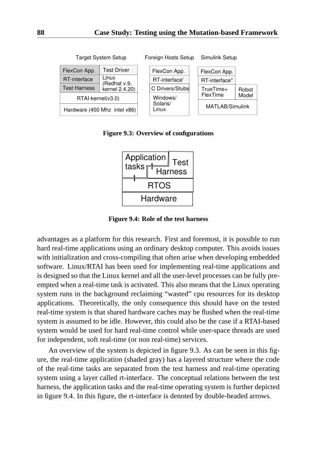
88 Case Study: Testing using the Mutation-based Framework
Hardware (450 Mhz intel x86)
RTAI-kernel(v3.0)
Linux(Redhat v.9, kernel 2.4.20)
FlexCon App.
RT-interface
Test Harness
Test Driver
Target System Setup
Windows/Solaris/Linux
FlexCon App.
RT-interface'
Foreign Hosts Setup
TrueTime+FlexTime
FlexCon App.
RT-interface''
Simulink Setup
C Drivers/Stubs
MATLAB/Simulink
RobotModel
Figure 9.3: Overview of configurations
Application tasks
Test Harness
RTOS
Hardware
Figure 9.4: Role of the test harness
advantages as a platform for this research. First and foremost, it is possible to runhard real-time applications using an ordinary desktop computer. This avoids issueswith initialization and cross-compiling that often arise when developing embeddedsoftware. Linux/RTAI has been used for implementing real-time applications andis designed so that the Linux kernel and all the user-level processes can be fully pre-empted when a real-time task is activated. This also means that the Linux operatingsystem runs in the background reclaiming “wasted” cpu resources for its desktopapplications. Theoretically, the only consequence this should have on the testedreal-time system is that shared hardware caches may be flushed when the real-timesystem is assumed to be idle. However, this could also be the case if a RTAI-basedsystem would be used for hard real-time control while user-space threads are usedfor independent, soft real-time (or non real-time) services.
An overview of the system is depicted in figure 9.3. As can be seen in this fig-ure, the real-time application (shaded gray) has a layered structure where the codeof the real-time tasks are separated from the test harness and real-time operatingsystem using a layer called rt-interface. The conceptual relations between the testharness, the application tasks and the real-time operating system is further depictedin figure 9.4. In this figure, the rt-interface is denoted by double-headed arrows.

9.2 A Flexcon Demonstrator Prototype 89
The motivation for the layered structure is to hide the test-instrumentation fromthe code of the application tasks and to make the robot application portable to otherreal-time platforms. Obviously the timing and order of tasks may be completely dif-ferent on non-real time hosts, but applications can be compiled and tested for logi-cal and syntactical correctness on any supported platform. The MATLAB/simulinktarget also makes it possible to test how the control application would interact witha simulated hardware robot, given that the assumptions about temporal behaviorare correct. In this context, the test driver in figure 9.3 runs in linux user-space andreads data files containing timeliness test cases into memory, so that it is availableas needed when a test run starts.
9.2.3 Test Harness
The test harness incorporates all the software needed for controlling and observinga test-run on the target system. The design of the test harness is critical for real-time systems since it often must be left in the operational system to avoid probeeffects. An important issue in this context is that the instrumentation code must notchange the execution behavior in other ways than increasing the execution time. Forexample, the application behavior could be significantly altered if calls to loggingfunctions were blocking.
According to Schutz (1993), the following significant events need to be instru-mented to capture an execution order of event-triggered real-time systems.
• Access to time
• Context switches
• Asynchronous interrupts
Apart from this, when testing timeliness it is necessary to log the start and endtime of each task instance so that it is possible to check that it executes within itstime constraints.
The instrumentation of interrupts can be added directly to the interrupt handlerfunctions. Access to time can be instrumented by logging the system calls used toaccess the system clock.
The order of context switches can be indirectly monitored by logging the in-vocation and completion of task instances. However, to obtain full information ofthe timing when a context switch occurs it is necessary to be able to insert probesin the system dispatcher. According to Schutz (1993), it is application dependentwhether the timing of these events is necessary or not.
90 Case Study: Testing using the Mutation-based Framework
Injecting Stimuli
During a test run sporadic stimuli should be injected at the points in time specifiedby the activation pattern part of timeliness test cases. To realize this, the test harnessfor the Flexcon application uses a sporadic task that emulates the interrupt-handlersin the system. This task reads an activation pattern specification from a FIFO-queue that has been populated by the test driver before testing starts. The activationpattern specification contains the type of the next sporadic task to be activated andan absolute point in time when it should be activated.
Since the test harness task for injecting stimuli executes on the highest priorityand does not share any resources with the application tasks, the execution distur-bance from this task is assumed to be short and similar to that of the emulatedinterrupt handlers. Further, the same mechanism is used to evaluate all the testsuites compared and therefore should not introduce any bias.
The activation of periodic tasks is handled by using the facilities provided bythe RTAI native interface. Hence, the periods and start times of tasks are specified atsystem initialization and activation (stimuli) are generated by the operating system.
Monitoring and Logging
In the current prototype implementation, all tasks log their own events in separatemain-memory buffers. Thus, no synchronization between real-time tasks is neces-sary for this purpose. The events in the log are time-stamped so they can be orderedand analyzed after the completion of a test run. The main-memory buffers are alsoaccessible from user space (as devices in the Linux file system), hence it is possibleto perform on-line analysis of test logs concurrently. In the following experiments,information from these main-memory buffers is collected after each test run, toavoid unnecessary competition for resources.
Only partial information about context switches is acquired in this application(through logging of task activation and completion times); the reason for this isto make sure that the test execution harness does not depend on features of theLinux/RTAI infrastructure. However, the information acquired is sufficient for de-termining the execution order of the application tasks and checking that tasks exe-cute within their time constraints. If necessary, context switch overhead times canbe approximated by the time a higher priority task (than the one currently running)is requested and the logged time when the task begins its execution.

9.2 A Flexcon Demonstrator Prototype 91
static void Spor_Thread2(int dummy) {
const int MyID = ID_FSENSORH;RT_TASK* ME = rt_whoami();
SPT2_data A;SPT2_init(&A,MyID);
rt_task_suspend(ME); // Init done waiting for test scope to start
while (SYS_STATE==Operative) {log(MyID,TS_Start);
SPT2_work(&A,MyID);log(MyID,TS_End);rt_task_suspend(ME);// Sporadic tasks remain suspended until invoked by// a new interrupt
}
}
Figure 9.5: RTAI-thread implementing sporadic task in test harness

92 Case Study: Testing using the Mutation-based Framework
static void Per_ThreadALLContr(int dummy) {
PT0_data A; // Local Data (think C++ object state data)PT1_data B;PT2_data C;
PT0_init(&A,ID_CONTR1);PT1_init(&B,ID_CONTR2);PT2_init(&C,ID_CONTR3);
rt_task_suspend(rt_whoami()); // Init done
while (rt_get_time()<end_time) {
PT0_work(&A,ID_CONTR1); // Invoke controller 1PT2_work(&C,ID_CONTR3); // Invoke controller 3rt_task_wait_period(); // wait until (P * n)+(P/4)
PT1_work(&B,ID_CONTR2); // Invoke controller 2rt_task_wait_period(); // wait until (P * n)+(P/2)
PT0_work(&A,ID_CONTR1); // Invoke controllerrt_task_wait_period(); // wait until (P * n)+(P * 3/4)
PT1_work(&B,ID_CONTR2); // Invoke controller 2rt_task_wait_period(); // wait until (P * n+1)
}rt_task_suspend(rt_whoami());
}
Figure 9.6: RTAI-thread implementing controller tasks in test harness

9.3 Applying the Framework for Testing of Timeliness 93
Task Support
The real-time tasks are implemented as functions that are free from semantics as-sociated with the target platform. The reason for this is to be able to support thelayered architecture suggested in section 9.2.2.
Hence, each real time task is assumed to have a data structure containing itslocal context (state variables), an “Init” function called once at the start-up of thesystem, and a “Work” function called at each invocation of the task. To supportconcurrency, each task is typically implemented using a dedicated operating systemthread that is responsible for logging and calling the task-functions at the right time.See figure 9.5 for an example of how a sporadic task is implemented. A similarthread is needed for each sporadic task and it is possible to parameterize the setupso that this indirection becomes transparent to the user of the test harness1.
It is also possible that tasks are implemented by more advanced threads, forexample, periodic tasks that share a common major cycle time can be implementedusing a single thread (see figure 9.6).
9.2.4 Task Implementation
The implementation of the robot application tasks is quite small, only approxi-mately 1000 lines of C code (excluding code in library function calls etc).
As previously mentioned, the implementation of this prototype contains somesimplifications, but is assumed to be detailed enough to be representative of smallcontrol applications. One simplification is that some parts are omitted, for exampleno hardware device drivers or networks stacks are implemented. The parts notimplemented are replaced with stubs (function calls) that make dummy operationsusing a busy delay primitive. A description of the implementation of the applicationtasks including source code extracts is available in Appendix A.
9.3 Applying the Framework for Testing of Timeliness
When performing system level testing of timeliness (according to the frameworkoutlined in chapter 5), tasks are requested as specified by the activation pattern partof timeliness test cases to exercise a particular execution order. During such a testrun the individual tasks are fed with input data that are good candidates for causinglong execution times or blocking times. This should stress the system to revealpotential timeliness failures.
1In this way the test harness can be adapted for other applications and target platforms
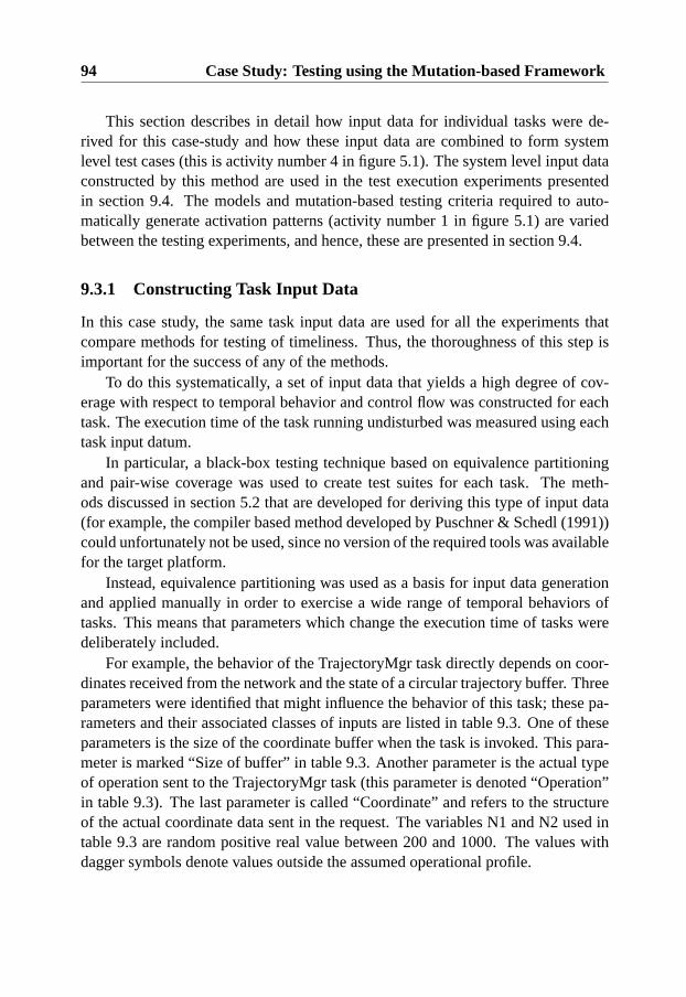
94 Case Study: Testing using the Mutation-based Framework
This section describes in detail how input data for individual tasks were de-rived for this case-study and how these input data are combined to form systemlevel test cases (this is activity number 4 in figure 5.1). The system level input dataconstructed by this method are used in the test execution experiments presentedin section 9.4. The models and mutation-based testing criteria required to auto-matically generate activation patterns (activity number 1 in figure 5.1) are variedbetween the testing experiments, and hence, these are presented in section 9.4.
9.3.1 Constructing Task Input Data
In this case study, the same task input data are used for all the experiments thatcompare methods for testing of timeliness. Thus, the thoroughness of this step isimportant for the success of any of the methods.
To do this systematically, a set of input data that yields a high degree of cov-erage with respect to temporal behavior and control flow was constructed for eachtask. The execution time of the task running undisturbed was measured using eachtask input datum.
In particular, a black-box testing technique based on equivalence partitioningand pair-wise coverage was used to create test suites for each task. The meth-ods discussed in section 5.2 that are developed for deriving this type of input data(for example, the compiler based method developed by Puschner & Schedl (1991))could unfortunately not be used, since no version of the required tools was availablefor the target platform.
Instead, equivalence partitioning was used as a basis for input data generationand applied manually in order to exercise a wide range of temporal behaviors oftasks. This means that parameters which change the execution time of tasks weredeliberately included.
For example, the behavior of the TrajectoryMgr task directly depends on coor-dinates received from the network and the state of a circular trajectory buffer. Threeparameters were identified that might influence the behavior of this task; these pa-rameters and their associated classes of inputs are listed in table 9.3. One of theseparameters is the size of the coordinate buffer when the task is invoked. This para-meter is marked “Size of buffer” in table 9.3. Another parameter is the actual typeof operation sent to the TrajectoryMgr task (this parameter is denoted “Operation”in table 9.3). The last parameter is called “Coordinate” and refers to the structureof the actual coordinate data sent in the request. The variables N1 and N2 used intable 9.3 are random positive real value between 200 and 1000. The values withdagger symbols denote values outside the assumed operational profile.

9.3 Applying the Framework for Testing of Timeliness 95
Size of buffer Operation Coordinate0 Insert (N1,N2,1.57)15 Move All (-N1,N2,0.0)99 Adjust (10) (N1, -N2, 3.15)†100 Adjust (99) (0,0,0.0)†
Table 9.3: Equivalence partitioning of TrajectoryMgr
From this equivalence partitioning, each parameter is pair-wise combined witheach of the other parameters. Table 9.4 lists an example suite that provides pair-wise coverage of the parameter values in table 9.3.
After input data were created, each task was run on the target system withoutany disturbances from other application tasks. For each input datum the task wasactivated periodically 20 times, and the procedure was repeated 5 times. The sta-tistics of the tasks execution behavior for a particular input datum, over these 100invocations, were collected. Analysis tools were developed to automatically extractworst-case, best-case, mean, median and standard deviation of the execution timesfrom the logs. Based on these measurements it is possible to rank each task inputdatum with respect to the resulting execution time and execution pattern of the task.
These lists of input data for the different system tasks are then combined to cre-ate sets of test data for system level testing of timeliness where all the tasks are runconcurrently. The equivalence partitioning, input data specifications and the resultsfrom the measurements of the tasks in the Flexcon demonstrator application areavailable in Appendix B. From the measurements it can be concluded that hard-ware caching has a significant impact on the execution times for this applicationand platform.
9.3.2 Combining Task Input Data for System Level Testing
Before starting system level testing on the target system it is necessary to choosewhich input data for the different tasks should be combined when tasks run con-currently. An intuitive choice is to combine all the input data that cause the longestexecution time into one single set of input data to use for all the test runs. However,if only one set of input data is used then it is possible that only a small fractionof the actual code is executed during system level testing. Furthermore, anomaliesmight exist so that input data which cause a short execution time during measure-ments (when the task is executing undisturbed) cause a disproportionately longerexecution time when a task is executed concurrently with other tasks.
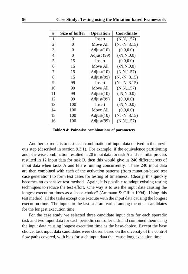
96 Case Study: Testing using the Mutation-based Framework
# Size of buffer Operation Coordinate1 0 Insert (N,N,1.57)2 0 Move All (N, -N, 3.15)3 0 Adjust(10) (0,0,0.0)4 0 Adjust (99) (-N,N,0.0)5 15 Insert (0,0,0.0)6 15 Move All (-N,N,0.0)7 15 Adjust(10) (N,N,1.57)8 15 Adjust(99) (N, -N, 3.15)9 99 Insert (N, -N, 3.15)10 99 Move All (N,N,1.57)11 99 Adjust(10) (-N,N,0.0)12 99 Adjust(99) (0,0,0.0)13 100 Insert (-N,N,0.0)14 100 Move All (0,0,0.0)15 100 Adjust(10) (N, -N, 3.15)16 100 Adjust(99) (N,N,1.57)
Table 9.4: Pair-wise combinations of parameters
Another extreme is to test each combination of input data derived in the previ-ous step (described in section 9.3.1). For example, if the equivalence partitioningand pair-wise combination resulted in 20 input data for task A and a similar processresulted in 12 input data for task B, then this would give us 240 different sets ofinput data when tasks A and B are running concurrently. These 240 input dataare then combined with each of the activation patterns (from mutation-based testcase generation) to form test cases for testing of timeliness. Clearly, this quicklybecomes an expensive test method. Again, it is possible to adopt existing testingtechniques to reduce the test effort. One way is to use the input data causing thelongest execution times as a “base-choice” (Ammann & Offutt 1994). Using thistest method, all the tasks except one execute with the input data causing the longestexecution time. The inputs to the last task are varied among the other candidatesfor the longest execution time.
For the case study we selected three candidate input data for each sporadictask and two input data for each periodic controller task and combined them usingthe input data causing longest execution time as the base-choice. Except the basechoice, task input data candidates were chosen based on the diversity of the controlflow paths covered, with bias for such input data that cause long execution time.
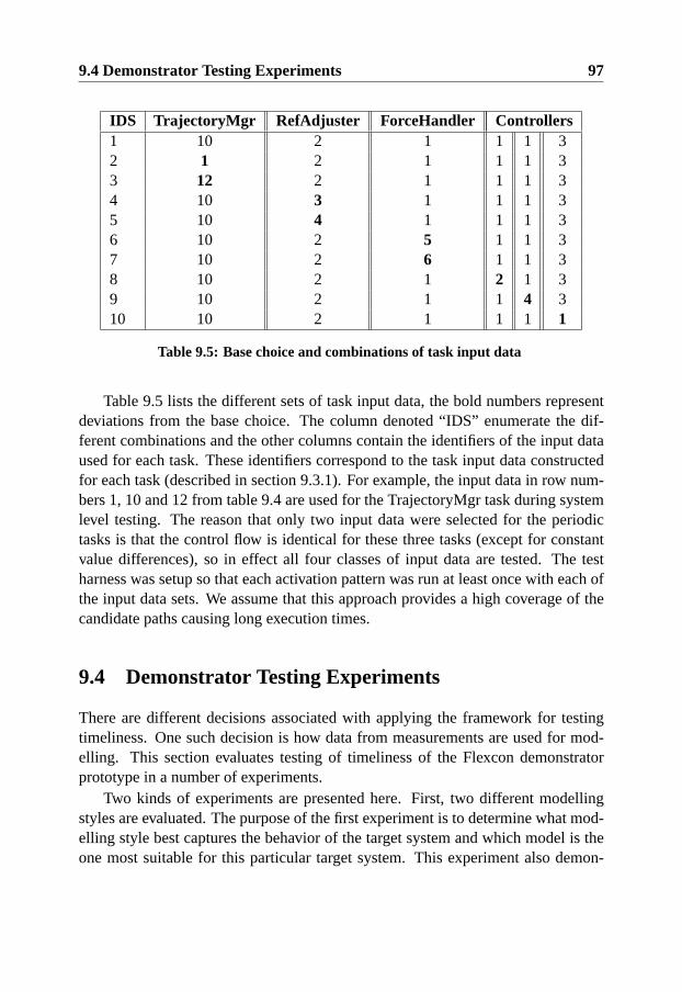
9.4 Demonstrator Testing Experiments 97
IDS TrajectoryMgr RefAdjuster ForceHandler Controllers1 10 2 1 1 1 32 1 2 1 1 1 33 12 2 1 1 1 34 10 3 1 1 1 35 10 4 1 1 1 36 10 2 5 1 1 37 10 2 6 1 1 38 10 2 1 2 1 39 10 2 1 1 4 310 10 2 1 1 1 1
Table 9.5: Base choice and combinations of task input data
Table 9.5 lists the different sets of task input data, the bold numbers representdeviations from the base choice. The column denoted “IDS” enumerate the dif-ferent combinations and the other columns contain the identifiers of the input dataused for each task. These identifiers correspond to the task input data constructedfor each task (described in section 9.3.1). For example, the input data in row num-bers 1, 10 and 12 from table 9.4 are used for the TrajectoryMgr task during systemlevel testing. The reason that only two input data were selected for the periodictasks is that the control flow is identical for these three tasks (except for constantvalue differences), so in effect all four classes of input data are tested. The testharness was setup so that each activation pattern was run at least once with each ofthe input data sets. We assume that this approach provides a high coverage of thecandidate paths causing long execution times.
9.4 Demonstrator Testing Experiments
There are different decisions associated with applying the framework for testingtimeliness. One such decision is how data from measurements are used for mod-elling. This section evaluates testing of timeliness of the Flexcon demonstratorprototype in a number of experiments.
Two kinds of experiments are presented here. First, two different modellingstyles are evaluated. The purpose of the first experiment is to determine what mod-elling style best captures the behavior of the target system and which model is theone most suitable for this particular target system. This experiment also demon-
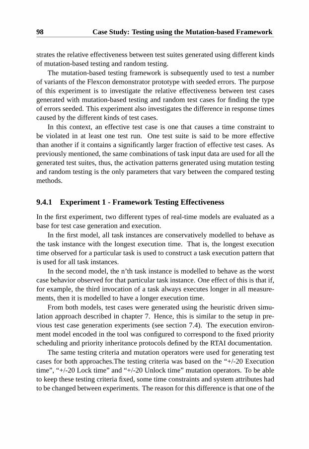
98 Case Study: Testing using the Mutation-based Framework
strates the relative effectiveness between test suites generated using different kindsof mutation-based testing and random testing.
The mutation-based testing framework is subsequently used to test a numberof variants of the Flexcon demonstrator prototype with seeded errors. The purposeof this experiment is to investigate the relative effectiveness between test casesgenerated with mutation-based testing and random test cases for finding the typeof errors seeded. This experiment also investigates the difference in response timescaused by the different kinds of test cases.
In this context, an effective test case is one that causes a time constraint tobe violated in at least one test run. One test suite is said to be more effectivethan another if it contains a significantly larger fraction of effective test cases. Aspreviously mentioned, the same combinations of task input data are used for all thegenerated test suites, thus, the activation patterns generated using mutation testingand random testing is the only parameters that vary between the compared testingmethods.
9.4.1 Experiment 1 - Framework Testing Effectiveness
In the first experiment, two different types of real-time models are evaluated as abase for test case generation and execution.
In the first model, all task instances are conservatively modelled to behave asthe task instance with the longest execution time. That is, the longest executiontime observed for a particular task is used to construct a task execution pattern thatis used for all task instances.
In the second model, the n’th task instance is modelled to behave as the worstcase behavior observed for that particular task instance. One effect of this is that if,for example, the third invocation of a task always executes longer in all measure-ments, then it is modelled to have a longer execution time.
From both models, test cases were generated using the heuristic driven simu-lation approach described in chapter 7. Hence, this is similar to the setup in pre-vious test case generation experiments (see section 7.4). The execution environ-ment model encoded in the tool was configured to correspond to the fixed priorityscheduling and priority inheritance protocols defined by the RTAI documentation.
The same testing criteria and mutation operators were used for generating testcases for both approaches.The testing criteria was based on the “+/-20 Executiontime”, “+/-20 Lock time” and “+/-20 Unlock time” mutation operators. To be ableto keep these testing criteria fixed, some time constraints and system attributes hadto be changed between experiments. The reason for this difference is that one of the
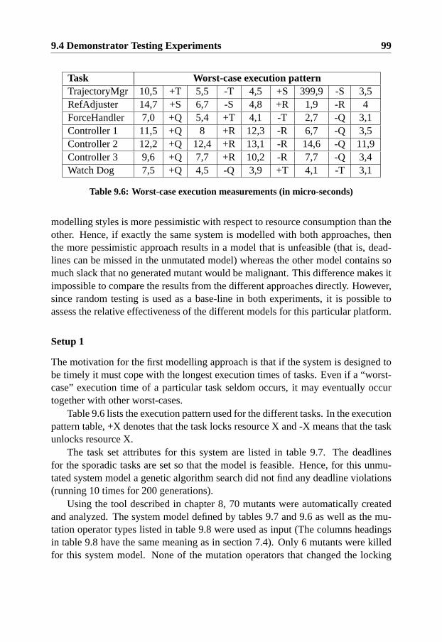
9.4 Demonstrator Testing Experiments 99
Task Worst-case execution patternTrajectoryMgr 10,5 +T 5,5 -T 4,5 +S 399,9 -S 3,5RefAdjuster 14,7 +S 6,7 -S 4,8 +R 1,9 -R 4ForceHandler 7,0 +Q 5,4 +T 4,1 -T 2,7 -Q 3,1Controller 1 11,5 +Q 8 +R 12,3 -R 6,7 -Q 3,5Controller 2 12,2 +Q 12,4 +R 13,1 -R 14,6 -Q 11,9Controller 3 9,6 +Q 7,7 +R 10,2 -R 7,7 -Q 3,4Watch Dog 7,5 +Q 4,5 -Q 3,9 +T 4,1 -T 3,1
Table 9.6: Worst-case execution measurements (in micro-seconds)
modelling styles is more pessimistic with respect to resource consumption than theother. Hence, if exactly the same system is modelled with both approaches, thenthe more pessimistic approach results in a model that is unfeasible (that is, dead-lines can be missed in the unmutated model) whereas the other model contains somuch slack that no generated mutant would be malignant. This difference makes itimpossible to compare the results from the different approaches directly. However,since random testing is used as a base-line in both experiments, it is possible toassess the relative effectiveness of the different models for this particular platform.
Setup 1
The motivation for the first modelling approach is that if the system is designed tobe timely it must cope with the longest execution times of tasks. Even if a “worst-case” execution time of a particular task seldom occurs, it may eventually occurtogether with other worst-cases.
Table 9.6 lists the execution pattern used for the different tasks. In the executionpattern table, +X denotes that the task locks resource X and -X means that the taskunlocks resource X.
The task set attributes for this system are listed in table 9.7. The deadlinesfor the sporadic tasks are set so that the model is feasible. Hence, for this unmu-tated system model a genetic algorithm search did not find any deadline violations(running 10 times for 200 generations).
Using the tool described in chapter 8, 70 mutants were automatically createdand analyzed. The system model defined by tables 9.7 and 9.6 as well as the mu-tation operator types listed in table 9.8 were used as input (The columns headingsin table 9.8 have the same meaning as in section 7.4). Only 6 mutants were killedfor this system model. None of the mutation operators that changed the locking
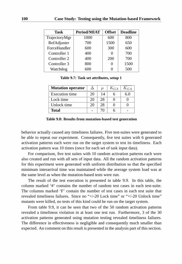
100 Case Study: Testing using the Mutation-based Framework
Task Period/MIAT Offset DeadlineTrajectoryMgr 1000 600 800RefAdjuster 700 1500 650
ForceHandler 600 300 600Controller 1 400 0 700Controller 2 400 200 700Controller 3 800 0 1500Watchdog 600 0 500
Table 9.7: Task set attributes, setup 1
Mutation operator ∆ µ KGA KGA
Execution time 20 14 6 6.0Lock time 20 28 0 0Unlock time 20 28 0 0Total - 70 6 -
Table 9.8: Results from mutation-based test generation
behavior actually caused any timeliness failures. Five test-suites were generated tobe able to repeat our experiment. Consequently, five test suites with 6 generatedactivation patterns each were run on the target system to test its timeliness. Eachactivation pattern was 10 times (once for each set of task input data).
For comparison, five test suites with 10 random activation patterns each werealso created and run with all sets of input data. All the random activation patternsfor this experiment were generated with uniform distribution so that the specifiedminimum interarrival time was maintained while the average system load was atthe same level as when the mutation-based tests were run.
The result of the test execution is presented in table 9.9. In this table, thecolumn marked ‘#’ contains the number of random test cases in each test-suite.The columns marked ‘F’ contain the number of test cases in each test suite thatrevealed timeliness failures. Since no “+/-20 Lock time” or “+/-20 Unlock time”mutants were killed, no tests of this kind could be run on the target system.
From table 9.9, it can be seen that two of the 50 random activation patternsrevealed a timeliness violation in at least one test run. Furthermore, 3 of the 30activation patterns generated using mutation testing revealed timeliness failures.The difference in effectiveness is negligible and consequently much smaller thanexpected. An comment on this result is presented in the analysis part of this section.
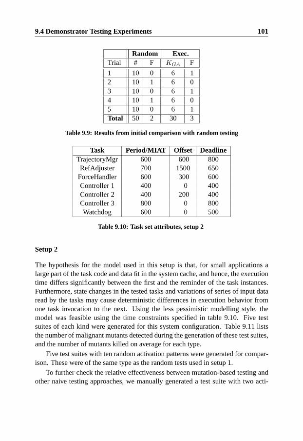
9.4 Demonstrator Testing Experiments 101
Random Exec.Trial # F KGA F
1 10 0 6 12 10 1 6 03 10 0 6 14 10 1 6 05 10 0 6 1Total 50 2 30 3
Table 9.9: Results from initial comparison with random testing
Task Period/MIAT Offset DeadlineTrajectoryMgr 600 600 800RefAdjuster 700 1500 650
ForceHandler 600 300 600Controller 1 400 0 400Controller 2 400 200 400Controller 3 800 0 800Watchdog 600 0 500
Table 9.10: Task set attributes, setup 2
Setup 2
The hypothesis for the model used in this setup is that, for small applications alarge part of the task code and data fit in the system cache, and hence, the executiontime differs significantly between the first and the reminder of the task instances.Furthermore, state changes in the tested tasks and variations of series of input dataread by the tasks may cause deterministic differences in execution behavior fromone task invocation to the next. Using the less pessimistic modelling style, themodel was feasible using the time constraints specified in table 9.10. Five testsuites of each kind were generated for this system configuration. Table 9.11 liststhe number of malignant mutants detected during the generation of these test suites,and the number of mutants killed on average for each type.
Five test suites with ten random activation patterns were generated for compar-ison. These were of the same type as the random tests used in setup 1.
To further check the relative effectiveness between mutation-based testing andother naive testing approaches, we manually generated a test suite with two acti-
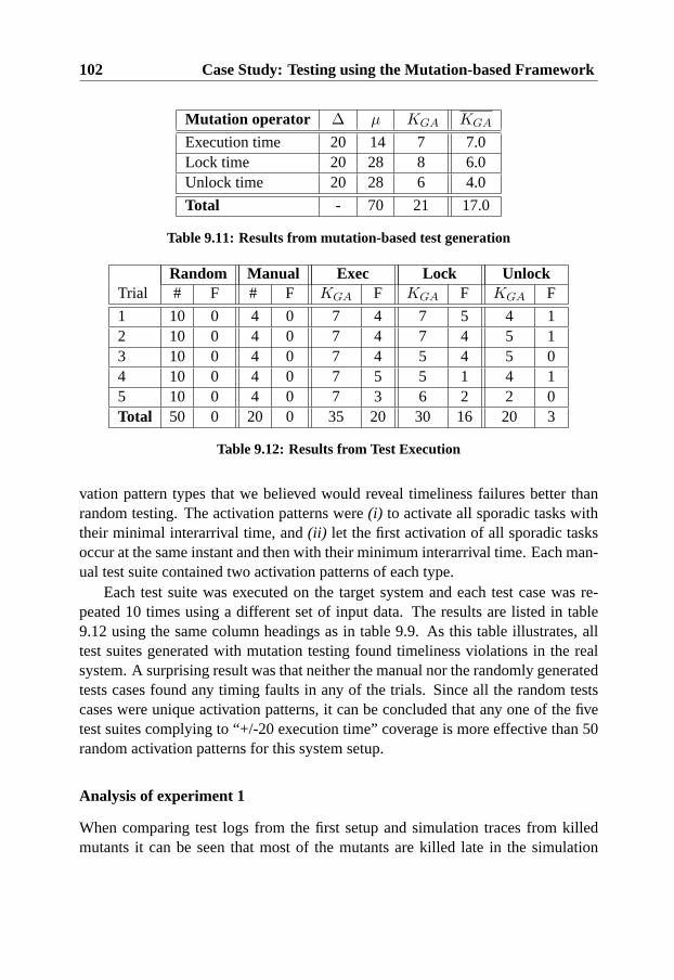
102 Case Study: Testing using the Mutation-based Framework
Mutation operator ∆ µ KGA KGA
Execution time 20 14 7 7.0Lock time 20 28 8 6.0Unlock time 20 28 6 4.0
Total - 70 21 17.0
Table 9.11: Results from mutation-based test generation
Random Manual Exec Lock UnlockTrial # F # F KGA F KGA F KGA F
1 10 0 4 0 7 4 7 5 4 12 10 0 4 0 7 4 7 4 5 13 10 0 4 0 7 4 5 4 5 04 10 0 4 0 7 5 5 1 4 15 10 0 4 0 7 3 6 2 2 0Total 50 0 20 0 35 20 30 16 20 3
Table 9.12: Results from Test Execution
vation pattern types that we believed would reveal timeliness failures better thanrandom testing. The activation patterns were(i) to activate all sporadic tasks withtheir minimal interarrival time, and(ii) let the first activation of all sporadic tasksoccur at the same instant and then with their minimum interarrival time. Each man-ual test suite contained two activation patterns of each type.
Each test suite was executed on the target system and each test case was re-peated 10 times using a different set of input data. The results are listed in table9.12 using the same column headings as in table 9.9. As this table illustrates, alltest suites generated with mutation testing found timeliness violations in the realsystem. A surprising result was that neither the manual nor the randomly generatedtests cases found any timing faults in any of the trials. Since all the random testscases were unique activation patterns, it can be concluded that any one of the fivetest suites complying to “+/-20 execution time” coverage is more effective than 50random activation patterns for this system setup.
Analysis of experiment 1
When comparing test logs from the first setup and simulation traces from killedmutants it can be seen that most of the mutants are killed late in the simulation
9.4 Demonstrator Testing Experiments 103
trace whereas almost all deadline violations in the real system are detected whentasks are activated for the first time. It is also evident that the simulated task in-stances execute much longer than the real software tasks on average. This effect isparticularly evident late in the simulation trace.
We believe that this behavior is due to the large size of hardware caches andthe relatively complex caching architecture of the target system. After the firstinvocation of a task all the source code and local data for a task may have beencopied to the cache memory (first or second level). Since each real-time applicationtask is activated with a high frequency (relative to other threads running in Linuxuser-space) the probability that the data used by the the real-time tasks remain inthe cache is high.
The effect of this discrepancy between the model and the real system’s behavioris that the heuristic search algorithm often creates an activation pattern to stressa critical interval late in the simulation. However, on the target system, the realexecution time is much shorter than in the simulation in this interval, and hence,the generated activation pattern is unlikely to reveal any timeliness failures.
This effect is compensated by the modelling style applied in experiment setup2. By modelling the task instances separately, the simulated model is more similarto the system behavior. Consequently, the heuristic search algorithm has a betterchance of identifying the activation patterns that also stress the real system imple-mentation. The improvement in the relative effectiveness of the mutation-based testsuites for the second setup indicates that the mutation-based framework is sensitiveto large mistakes in execution pattern modelling. This implies that it is useful toexploit feedback from measurements collected during unit testing and not be overlypessimistic when creating models for system level testing purposes.
Another observation is that for both experiment setups there exist intervals inthe test logs in which no real-time task is allowed to run even if several tasks havebeen requested for execution. We assume this is caused by platform overheads anddisturbances that are not part of the model.
If overheads of this type occur deterministically for certain execution orders ortask executions, then they can be treated as a difference between the model andthe implementation and included in the execution environment model for a newiteration of analysis and test case generation. However, transient faults that cannotbe controlled or predicted are difficult to model in a meaningful way.
Once transient faults have been identified as causing timeliness failures, thereare two ways of proceeding. The preferred way when building a real-time system istrying to identify the causes of the transient timeliness faults (unpredictability) andremoving them from the system. If that is not possible (which may be the case when
104 Case Study: Testing using the Mutation-based Framework
building real-time systems with off-the-shelf hardware and software components),extra computing resources can be included, or features removed so there is slack inthe system to cope with the “noise” introduced by the transient faults.
A problem in this context is estimating the amount of slack needed to avoidtimeliness failures in the new system. The only way to gain confidence in a suchsystem may be testing since traditional analysis methods for real-time systems typ-ically do not cope well with unpredictable disturbances (Burns & Wellings 2001).Further, by allowing this types of timeliness faults in the system, the effectivenessof timeliness testing methods is also negatively affected since test cases must berun more times to obtain reliable results. In addition, it is generally impossible toknow if the worst case has been observed for a particular test case.
9.4.2 Experiment 2 - Effectiveness with Seeded Errors
The purpose of this experiment is to investigate the effectiveness of mutation-basedtesting when the target system is designed to cope with some transient timelinessfaults. In particular, we investigated the relative effectiveness of the test suites intesting system variants with both seeded errors and transient faults2. We comparedthe results for different levels of slack to discover how much the different test suitesstress the non-deterministic system.
For this experiment, we created a number of variants of the Flexcon demonstra-tor application with seeded errors by adding a busy delay at a random point in thetasks code. The error seeding was controlled so that each task was affected by oneerror. The basic block in the task code where the error was injected was chosen byrandom. This means that the error can occur within a condition statement or in acode segment where a shared resource is locked. The size of the busy delay addedto the source code was 80 microseconds. Table 9.13 summarizes the result of theerrors seeding for different variants of the system.
Since this experiment required running 7 times as many tests, we only did acomparison between random testing and one of the mutation-based testing criteria(approximately 6000 test runs were executed for this experiment). In particular,five “+/-20 execution time” test suites and five random test suites from experimentone were rerun on each of the 7 variants of the target system.
As an example, figure 9.7 shows the number of effective test cases for two testsuites executed on variant 7. In this figure, the solid line is the test cases generatedwith mutation-based testing and the dashed line represents the random test cases.
2These remains in the seeded variants since we could not easily fix the transient faults detected inthe first experiment.

9.4 Demonstrator Testing Experiments 105
Version Task Resources1 TrajectoryMgr S2 Refadjuster -3 Force handler Q&T4 Controller 1 Q5 Controller 2 Q&R6 Controller 3 -7 Watch-dog T
Table 9.13: Software variants and affected entities of seeded errrors
0 50 100 150 200 250 300 350 400 4500
2
4
6
8
Lateness
Effe
ctiv
e T
est C
ases
Figure 9.7: Failures detected in variant 7 of the system

106 Case Study: Testing using the Mutation-based Framework
12
34
56
7 50150
250350
450
0
2
4
6
8
10
LatenessSoftware Version
Effe
ctiv
e T
est C
ases
Figure 9.8: Failures detected in seeded variants with random testing
Point 0 on the x-axis indicates the number of effective test cases (using the y-axis),assuming the deadlines listed in table 9.10. The values along the x-axis representan iterative increase (in steps of 50 microseconds) of all the deadlines in table 9.10.Since there is 7 mutation-based test cases and 10 random test cases in a test suite,the maximum of the solid line is 7 whereas the maximum of the dashed line is10. The graph is not normalized to maintain visibility of the number of test casesleading to failures. This type of graph indicates how many test cases in each testsuite cause deadlines to be missed and how late the system responds when testedwith different kind of test suites.
An overview of the results for all the software variants is presented as a surfaceplot in figures 9.8 and 9.9. These figures contains the results of the most effectivetest suites for each software variant with seeded faults. The graphs contain thesame information as in figure 9.7, but each of the variants is plotted on the z-axis.Similar plots for the least effective test suites and the mean effectiveness is givenin Appendix C.
From these surface plots it can be seen that the test suites generated withmutation-based testing contain a larger percentage of effective test cases, and con-sistently reveal behaviors with longer response times than random testing.

9.4 Demonstrator Testing Experiments 107
12
34
56
7 50150
250350
450
0
2
4
6
8
10
LatenessSoftware Version
Effe
ctiv
e T
est C
ases
Figure 9.9: Failures detected in seeded variants with mutation testing
Analysis of experiment 2
This experiment indicates that a large fraction of the mutation-based test cases re-mains effective for finding seeded errors when the slack in the system is increasedto compensate for some transient errors.
A remarkable observation is that even after the software has been seeded withdeterministic timeliness errors, test cases with random activation patterns are oftenincapable of causing any deadlines to be missed. This indicates that a system testedonly with random activation patterns can contain many potential timeliness errorsthat are never revealed.
For example, if variant two of the system implementation was tested using 50random activation patterns (that is, 500 test runs with different combinations oftask input data and activation patterns) no deadline violations would be detected3.In the trial with the least effective mutation-based tests (see figure C.2 in AppendixC), five of the timeliness test cases reveal missed deadlines in this system and the
3If we assume that the performance of executing random activation patterns is comparable to thesimulation experiments with random search, described in section 7.4, then it is likely that randomtesting will perform badly even if the number of random tests are significantly increased.
108 Case Study: Testing using the Mutation-based Framework
system was stressed so that a deadline was missed with over 200 microseconds(this trial consisted of 70 test runs). These results support the claim from section3.4 that methods for testing of timeliness benefit from exploiting information aboutthe internal behavior of real-time systems.
There are some issues concerning the setup of this experiment, that need to bediscussed. One such issue is that the errors seeded during experiment two are bigin relation to the measured execution behavior of tasks. The reason for this is thatthe increase in system slack adds a “dampening” effect which makes small errorsdifficult to detect. By adding big timeliness errors we increase the probability ofa deadline being missed in a system with additional slack and this makes it easierto compare the testing approaches. A more thorough discussion related to seedingtimeliness errors is available in section 10.4.1.
Another important note is that execution orders are independent of the amountof slack in the system when using fixed priority scheduling protocols. This is notthe case when using other execution environments. It is, thus possible that theeffectiveness of mutation-based test suites for such systems is more sensitive toincreasing the slack. Hence, the comparison presented in this section may notnecessarily generalize to systems with dynamic priority schedulers.
Chapter 10
Discussion
This chapter contains a discussion of the methods and experiments presented in thisthesis. Furthermore, some related ideas that remain to be evaluated are presented.
Referring to the framework overview in figure 5.1, issues relating to testingcriteria and model analysis (activity 1 and 2) are discussed in section 10.1, aspectsof test case generation (activity 3) are discussed in section 10.2 and a discussion ofhow test execution (activity 5) can be performed in a way that exploits mutation-based test case generation is found in section 10.3. Task input data generationand test analysis (activities 4 and 6) are not addressed in this chapter, since nosignificant contributions have been made for these activities.
Finally, section 10.4 contains a discussion of issues relating to validation andthe research presented in this thesis.
10.1 Mutation Operators and Testing Criteria
When discussing mutation-based testing criteria, three issues need to be addressed.These are(i) comprehensiveness,(ii) meaningfulness, and(iii) cost effectiveness.
In this context, comprehensiveness means, that for all errors that might lead totimeliness failures of a tested system, a corresponding mutation operator is defined.A mutation operator is considered meaningful if it creates at least one malignantmutant. It could also be argued that a meaningful mutation operator should gen-erate mutants which represent some error type that actually can occur during thedesign or implementation of real-time systems. This property is more difficult to
109
110 Discussion
evaluate, but if it is possible to come up with examples of faults that would causesuch an error (such as described in section 6.3), then it is likely that the operator ismeaningful even under that definition. A mutation operator is not cost effective ifit creates a huge number of rarely malignant mutants.
As previously mentioned, it is generally impossible to show that a set of muta-tion operators is comprehensive. Further, it is possible that some mutation opera-tors are not meaningful or too expensive for a specific system (for example, due toproperties enforced by real-time protocols).
These issues are encountered for most types of mutation testing, and knowledgeof comprehensiveness, meaningfulness and cost effectiveness typically develop asa testing method matures and is used in different situations.
For comparison, a set of mutation operators for class testing (object-orientedtesting) were first presented by Kim, Clark & McDermid (2000). These were usedand refined by Chevalley & Thevenod-Fosse (2002) two years later. At the sametime Offutt et al. developed a categorization for object oriented programming faults(Offutt, Alexander, Y.Wu, Xiao & Hutchinson 2001). This resulted in a more com-prehensive set of mutation operators for the Mujava tool (Ma et al. 2005). However,subsequent experimental studies revealed that some of the mutation operators wereexpensive compared to their fault finding capability when used on a set of opensource systems, whereas other operators were determined to be meaningless sincethey only produced benign mutants (Offutt, Ma & Kwon 2006).
With this analogy in mind, our current impression is that the mutation operatortypes in section 6.3 provide a comprehensive set of mutations which are meaningfulfor real-time applications that can be modelled with the TAT notation. Subsection10.1.1 also presents some additional variants of mutation operators and subsection10.1.2 describes how new mutation operators could be integrated to the proposedtesting framework.
In this thesis, we generated mutation-based test cases for a small real-time ap-plication (see section 9.3) and some different types of hypothetical real-time systemmodels (see section 7.4). It is thus too early to make general statements about theoverall cost effectiveness of the mutation operators in section 6.3. However, ourfirst impression is that the mutation operators which indirectly increase the loadin potentially critical intervals (for example,∆+ execution time mutants or∆−inter-arrival time mutants) are more cost effective than the corresponding muta-tions which decrease the system load. This is intuitive, since the load of real-timesystems is directly related to timeliness, whereas other types of mutations typi-cally cause timeliness failures via increased blocking times and race conditions.On the other hand, timeliness faults leading to dangerous race conditions may be

10.1 Mutation Operators and Testing Criteria 111
hard to reveal using other testing methods (for example, brute force random test-ing on a non-deterministic platform), and hence, the low cost effectiveness and theincreased computation effort might be acceptable in some situations.
10.1.1 System Specific Mutation Operators
As previously discussed, the mutation operators evaluated in this thesis are onlycomprehensive for applications that comply with the TAT real-time applicationmodel notation. This excludes some fault types that might lead to timeliness fail-ures in some specific systems.
For example, the TAT notation presented in section 6.2 assumes that each re-source is locked and unlocked by the same task instance before it terminates. Inpractice, this means that the handling of semaphores must be encapsulated andused only for protecting critical sections. This is typically the case if concurrencycontrol is provided to the user in the form of mechanisms such as condition criticalregions (where a compile-time warning is issued if a semaphore is incorrectly used)or monitors (where locking and unlocking is handled implicitly when entering andexiting monitor functions).
Unfortunately, not all execution environments for real-time applications en-force programmers to use such well behaved concurrency control mechanisms1.
Further, in some systems, low level mechanisms such as semaphores might beused for synchronization between tasks, or for modelling some condition in thesystems environment. For such situations, the basic TAT notation is not sufficientto accurately model the possible execution orders in the target system.
However, the simulation based approach for test-case generation and the flex-time tool is designed in such a way that it can still be used to support many exten-sions. System specific extensions to the notation for real-time application modelsand new types of mutation operators might therefore be needed to automaticallygenerate effective test cases. It is unclear if these kinds of extensions can be addedto a model checker tool so that the schedulability analysis used for killing mu-tants can still be performed. If the simulation based approach is used, it should bestraightforward to add such extensions to the execution order analysis.
An example of such a mutation operator and the and associated extensions fol-low. However, we have not conducted any experiments with these extensions.
1Despite many efforts in academia to raise the abstraction of real-time system design and imple-mentation, many real-time operating systems and platforms still assume that low-level languages andsynchronization mechanisms are used directly.
112 Discussion
Lock omission mutantIn a system where semaphores must be manually set for protecting critical sectionsit might be the case that unlocking a resource is not only delayed, but completelyomitted. Hence, the “lock omission” mutation operator removes the operations2
that lock or unlock resources.Omitting the operation where a resource is locked does not have a direct ef-
fect on timeliness. However, since a mutual exclusion constraint is violated, it ispossible that a logical error eventually occurs which changes the control flow sothat tasks behave differently than expected. The effect of omitting the operation inwhich a resource is unlocked is much more severe, since any other real-time taskswhich need to lock that resource are blocked indefinitely.
In addition, elusive race conditions might occur if a system contains errors inwhich both lock and unlock operations for a particular resource are omitted bydifferent tasks.
To support this type of mutation operator, the notation for resource lockingwould have to be extended with a special symbol†, representing “never”. With thisextended notation, the setSEM could contain tuples in any of the forms(s, t1, t2),(s, t1, †), (s, †, t2). Given this extension, the lock point omission operators can bedefined.
Mutation Operator 15 unlock omission:Given a TAT model with task set P, for every task(ci, di, SEMi, PRECi) ∈ Pand every semaphore use(s, t1, t2) ∈ SEMi, create one mutant in whicht2 ischanged to†.
Mutation Operator 16 lock omission:Given a TAT model with task set P, for every task(ci, di, SEMi, PRECi) ∈ Pand every semaphore use(s, t1, t2) ∈ SEMi, create one mutant in whicht1 ischanged to†.
10.1.2 Guidelines for Adding Mutation Operators
The mutation-based framework for testing of timeliness proposed in this thesis isintended to be general and support as many types of target systems as possible.However, it is not feasible to predict all possible target systems and all the possiblesystem specific mutation operators that might be desirable for comprehensiveness.Therefore, this section describes some guidelines for adding mutation operators.
2These are sometimes called the entry or exit protocols of a critical section.

10.1 Mutation Operators and Testing Criteria 113
In principle, mutation operators can be defined to add, remove or change theattributes of some entity or relation between entities in the real-time system model.For example, such entities are tasks and resources and attributes are execution timesand constraints on the inputs (see Appendix D).
The following guidelines are based on what kinds of extensions are directlysupported by the proposed notation and the design of the Flextime tool. This pro-vide an indication of how to model a particular hypothesized fault. We assumethat most of the guidelines also apply to extending a model-checking tool to per-form execution order analysis, but this depends on the design and limitations of theparticular model-checker.
Do not add errors that make the real-time model non-deterministic
If the simulation of a mutant with a particular activation pattern becomes non-deterministic (for example, by modelling the execution time of tasks as a randomdistribution), then it is difficult to determine if the activation pattern leads to adangerous execution order or not. Hence, the search for an effective activationpattern is disturbed. If a particular fault is transient, model the behavior when thefault occurs, find an activation pattern to reveal it, and run it multiple times on thenon-deterministic target system instead. This is a way to divide and conquer thetesting problem.
Combine the effect of existing mutation operators
This means that several mutation operators are applied to the same model, but po-tentially mutating different entities. For example, by applying two existing muta-tion operators (“∆− Interarrival time” and “∆− Execution time”) it is possible totest if a system is untimely when the period of task A is extended and the executiontime of task B is decreased. This does not require any changes in the notation forthe real-time system model. It is notable that one effect of specifying this type ofmutation is that one mutant is created for every possible combination.
Iteratively apply existing mutation operators
This means that several mutation operators are applied in series for mutating aspecific entity. For example, it is possible to test the consequences if the executiontime of task B is longer than expected and the point in time when a resource isunlocked is also delayed. This does not require any changes in the notation for thereal-time system model. Also, this kind of mutation becomes a specialization of

114 Discussion
an existing mutation operator so the maximum number of mutants created will notincrease.
Add or replace some real-time task
If timeliness errors can be modelled as real-time tasks which execute with a certainactivation pattern that is predictable or controllable during testing, then a mutationoperator could add such tasks to the system without changing the notation for thereal-time system model. For example, if a suspected error is that the applicationperiodically is disturbed by some undocumented kernel overhead (or a task createdby a COTS software module), but the frequency or what the consequences mightbe is unknown, then it is possible to create a mutation operator that adds differentvariants of a periodic task. The mutants are then analyzed to discover the malignantvariants and generate test cases that can reveal such behavior.
Inject or modify specialized execution segments
With a small extension to the TAT-notation and the FlexTime add-on it is possible tomodel timeliness errors by creating new types of execution items (see section 8.2).Mutation operators can then be specified that inject or modify execution items inthe execution pattern of tasks. For example, the system specific mutation opera-tor outlined in section 10.1.1 could be implemented with an operator that removesthe execution items which perform the locking and unlocking of resources. An-other example is adding an execution segment that cannot be preempted or one thatblocks the task and waits on a particular data dependency.
Modifying tasks instance execution patterns
As described in section 8.3, all the current mutation operators change a task execu-tion pattern so that the behaviors of all task instances are changed in the same way.The extended modelling style used in the case study described in section 9.4.1 andthe associated support in the timeliness testing tool (T 3) actually allow mutationoperators to change a subset of task instances. Hence, it is possible to create mu-tation operators that modify only one of the execution patterns. For example, it ispossible to create a mutant operator that change the second instance of task A toexecute twice as long as the previous one.
10.2 Test Case Generation Issues 115
Mutating some execution environment model property
The mutation-based test case generation approach proposed in this thesis typicallyassumes that the execution environment model is fixed for all mutants and that onlyproperties of the real-time application models are modified by mutation. However,if properties of the execution environment model are parameterized (so that changesdo not require recompilation of the kernel simulator), then it is possible to definemutation operators that change aspects of the execution environment. For exam-ple, a mutant can be that the priority inheritance protocol has been implementedincorrectly.
10.2 Test Case Generation Issues
The test case generation method proposed in this thesis is primarily associated withgenerating activation patterns for event-triggered tasks. Since the target platformcontains sources of non-determinism (for example caches), several different execu-tion orders are expected for a particular activation pattern of sporadic tasks. Oncea particular activation pattern has been generated the test execution techniques pre-sented by Thane and Pettersson (Thane 2000, Pettersson & Thane 2003) can beused to gain coverage of these expected execution orders. Furthermore, the execu-tion order descriptions generated by our approach provide added value since it ispossible to determine a subset of these execution orders that are most the relevantto cover for testing of timeliness. The generated execution orders can also be usedto support prefix-based testing (see section 10.3).
The execution order analysis performed during test case generation can be seenas a rudimentary form of automated sensitivity analysis for event-triggered real-time systems (c.f. Andersson, Wall & Norstrom (2006)). However, since we cannotguarantee that our method will find timeliness violations in a model, we do notclaim it is rigorous enough to be used this purpose. Testing has the fundamentallimitation that it can only show the presence of errors, but not their absence (Dahlet al. 1972). The heuristic-driven execution order analysis shares this property andshould therefore be used primarily for testing.
Another possibility is to take the activation patterns generated from mutatedmodels and simulate them on the un-mutated model. This can be seen as testingthe timeliness of the model. Obviously, this does not state anything about the prop-erties of the implemented system, but it is likely that such test cases can revealtimeliness violations in models difficult to analyze formally due to reachable statespace explosion.
116 Discussion
10.2.1 Scalability of Test Case Generation
As opposed to model-checking, the memory consumption does not increase asquickly as the reachable state space of the analyzed model when using a methodbased on heuristic driven simulation. In addition, the analysis can be halted anytime to give the current “best-try” for killing a mutant. Nevertheless, when testcases should be generated from complex system models, the computing time re-quired for on analyzing mutants increases. The following three factors contributeto this effect:
1. The number of mutants created by the selected mutation operators (for ful-filling a given test criteria) increases in a polynomial way with the number oftasks and resources, as outlined in section 6.3.
2. As the search problem expands, more iterations of the genetic algorithmsearch are required to gain confidence that all the malignant mutants havebeen killed. The impact of this factor depends on the characteristics of eachparticular search problem (c.f., Michalewicz & Fogel (1998)), for example,how many execution orders that kill a mutant or if those execution orderscorrespond to local optima which the heuristic cross overs are likely to exer-cise. Clearly, it is difficult to estimate the impact of this factor in a generalway.
3. The third factor is the time required for each simulation run in the fitnessfunction. The dominating variable in this context is the number of events inthe simulation interval and consequently the length of the simulation interval.The length of the simulation interval is determined by the hyper-period of theperiodic tasks, that is, the least common multiplier of their periods3. Hence,if there are many periodic tasks with relative prime periods, then the simula-tion interval may be long. However, this factor can be bounded to a constantby using a global offset as part of the genome and simulating a shorter sub-interval starting from that offset. With this modification, the simulation timecan be considered constant with respect to the input domain.
10.2.2 Genetic Algorithm Enhancements
The genetic algorithm suggested for generating test cases in this thesis should beconsidered a prototype for investigating the feasibility of the test case generation
3Plus the time for the longest offset in the task set
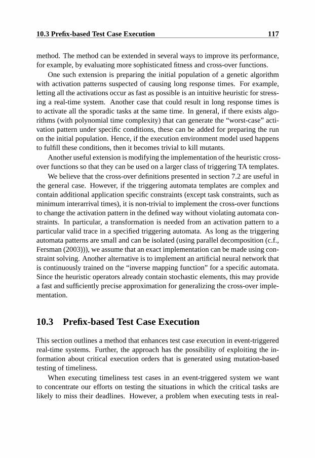
10.3 Prefix-based Test Case Execution 117
method. The method can be extended in several ways to improve its performance,for example, by evaluating more sophisticated fitness and cross-over functions.
One such extension is preparing the initial population of a genetic algorithmwith activation patterns suspected of causing long response times. For example,letting all the activations occur as fast as possible is an intuitive heuristic for stress-ing a real-time system. Another case that could result in long response times isto activate all the sporadic tasks at the same time. In general, if there exists algo-rithms (with polynomial time complexity) that can generate the “worst-case” acti-vation pattern under specific conditions, these can be added for preparing the runon the initial population. Hence, if the execution environment model used happensto fulfill these conditions, then it becomes trivial to kill mutants.
Another useful extension is modifying the implementation of the heuristic cross-over functions so that they can be used on a larger class of triggering TA templates.
We believe that the cross-over definitions presented in section 7.2 are useful inthe general case. However, if the triggering automata templates are complex andcontain additional application specific constraints (except task constraints, such asminimum interarrival times), it is non-trivial to implement the cross-over functionsto change the activation pattern in the defined way without violating automata con-straints. In particular, a transformation is needed from an activation pattern to aparticular valid trace in a specified triggering automata. As long as the triggeringautomata patterns are small and can be isolated (using parallel decomposition (c.f.,Fersman (2003))), we assume that an exact implementation can be made using con-straint solving. Another alternative is to implement an artificial neural network thatis continuously trained on the “inverse mapping function” for a specific automata.Since the heuristic operators already contain stochastic elements, this may providea fast and sufficiently precise approximation for generalizing the cross-over imple-mentation.
10.3 Prefix-based Test Case Execution
This section outlines a method that enhances test case execution in event-triggeredreal-time systems. Further, the approach has the possibility of exploiting the in-formation about critical execution orders that is generated using mutation-basedtesting of timeliness.
When executing timeliness test cases in an event-triggered system we wantto concentrate our efforts on testing the situations in which the critical tasks arelikely to miss their deadlines. However, a problem when executing tests in real-

118 Discussion
time systems is the controllability issue which is related to non-determinism (seesection 3.3). This leads to problems in ensuring that a particular execution orderhas been sufficiently tested.
As previously mentioned, most test case generation methods for testing timeli-ness are limited to generating activation patterns, that is, sequences of events withtime-stamps. However, the system-wide state in which these inputs occur is sel-dom specified in test cases. This implies that the same activation patterns must berun multiple times to gain confidence in the system’s behavior, hoping that someparticular execution order occurs. In some situations, this becomes problematic.As an example, consider the simple case when two tasks are executed on the sameprocessor and 70% of all the executions tasks are interleaved in the same way. Toreveal an error associated with the reversed execution order of these tasks, the sys-tem must be executed at least 13 times to give 99% probability of observing thereversed order one time. Further, assume that the error in this particular executionorder is only revealed using one of 100 input data. If non-deterministic testing isused we must execute and analyze 1300 tests to have a high probability of revealingthe error.
As discussed by Schutz (Schutz 1994), the number of possible execution or-ders grows very quickly with the number of activated tasks instances in an event-triggered system, hence, the probability of observing a specific execution order de-creases accordingly, even if a uniform distribution of execution orders is assumed4.
The alternative is to have some mechanism that controls the execution so that adesired execution order always occurs, or a mechanism that increases the probabil-ity that of an execution order occurring during testing.
However, when performing timeliness testing (and other time dependent test-ing), intrusive probes cannot be inserted in the execution environment during testexecution and then removed, as this would change the temporal behavior of thetested system so that it becomes different from the system used in operation (seesection 3.3). For the same reason, a “forced” execution must be exactly the same asa behavior that would occur without the enforcing mechanism. According to Shutz,it is difficult to force a single execution order without modifying the target systemin a way that alters its timing (Schutz 1993).
A potentially less intrusive approach to enhance the efficiency of test case exe-cutions is to increase the probability that a particular execution order occurs. Oneway of doing this is to include a state description as a test-prefix in each test case,and hence, enable a more controlled test execution even if no single execution order
4It is possible that some execution orders occur much more seldom than others, making it evenharder to reach them.
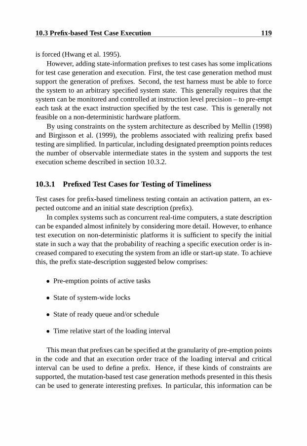
10.3 Prefix-based Test Case Execution 119
is forced (Hwang et al. 1995).However, adding state-information prefixes to test cases has some implications
for test case generation and execution. First, the test case generation method mustsupport the generation of prefixes. Second, the test harness must be able to forcethe system to an arbitrary specified system state. This generally requires that thesystem can be monitored and controlled at instruction level precision – to pre-empteach task at the exact instruction specified by the test case. This is generally notfeasible on a non-deterministic hardware platform.
By using constraints on the system architecture as described by Mellin (1998)and Birgisson et al. (1999), the problems associated with realizing prefix basedtesting are simplified. In particular, including designated preemption points reducesthe number of observable intermediate states in the system and supports the testexecution scheme described in section 10.3.2.
10.3.1 Prefixed Test Cases for Testing of Timeliness
Test cases for prefix-based timeliness testing contain an activation pattern, an ex-pected outcome and an initial state description (prefix).
In complex systems such as concurrent real-time computers, a state descriptioncan be expanded almost infinitely by considering more detail. However, to enhancetest execution on non-deterministic platforms it is sufficient to specify the initialstate in such a way that the probability of reaching a specific execution order is in-creased compared to executing the system from an idle or start-up state. To achievethis, the prefix state-description suggested below comprises:
• Pre-emption points of active tasks
• State of system-wide locks
• State of ready queue and/or schedule
• Time relative start of the loading interval
This mean that prefixes can be specified at the granularity of pre-emption pointsin the code and that an execution order trace of the loading interval and criticalinterval can be used to define a prefix. Hence, if these kinds of constraints aresupported, the mutation-based test case generation methods presented in this thesiscan be used to generate interesting prefixes. In particular, this information can be

120 Discussion
build initial state insert eventstime
save state monitor and log
phase 1 phase 2
lock dataobjects
T1T2
T3
Figure 10.1: Test execution phases
generated by injecting the test-case activation pattern on the mutated real-time sys-tem model and then store a snapshot of the simulation state just before the mutatedentity may affect the simulation.
In addition to the prefixes, the test case information specified in section 5.2 isstill required for prefix-based testing of timeliness.
10.3.2 A Prefix-based Test Case Execution Scheme
The first step in executing a test case with this scheme would be to run the systeminto the specified prefix state. Under a strict pessimistic concurrency control pol-icy, the active transactions have also acquired locks on all the required resources(Gray & Reuter 1993). Hence, serial execution up to the required transaction statesis possible while no time dependencies are reflected in the data objects (in Figure10.1; transactions T1, T2, and T3 are executed sequentially to specified preemp-tion points). Obviously, the state of the locked objects influences the executiontime of the individual transactions; hence, relevant states of shared objects shouldbe treated as task input data. Once each active task is executed to the specifiedpreemption point, they are combined into a concurrent prefix state. Pending trans-action tasks which have not yet been allowed to execute, but are part of the prefixspecification, are added to the ready queue. If a dynamic scheduler is used, it isassumed to have updated the ready queue as a direct response to incoming eventsand hence, one must allow it to build an initial schedule before the test executionbegins. At this point the specified prefix has been reached.
In the second phase the system is executed from the prefix state and inputs areexternally injected according to the activation pattern part of timeliness test cases.The behavior of the system is continuously monitored and logged using the event

10.4 Validation of Mutation-based Testing of Timeliness 121
monitoring facilities present in the architecture. The event logs are used after thetest case execution to verify that a correct execution order was observed and thatall the outputs occurred within their time constraints.
10.4 Validation of Mutation-based Testing of Timeliness
This section contains a discussion of the issues related to validating timeliness test-ing methods in general, and the hypotheses outlined in this thesis in particular.
10.4.1 Evaluating Timeliness Test Cases
A typical way of comparing the effectiveness of testing methods is runing test suitesto see which ones find the most faults. This requires access to a set of software thatcontains the type of faults used for comparison. There are three ways of obtainingto such software.
One is to use software systems that already contain faults. These may be faultsthat have been found, documented and corrected in a new release. It is also possibleto use non-tested software that has (at least not tested at this particular level or fora specific type of faults). This approach was used for the experiment described insection 9.4.1. A second way is to automatically seed faults in an assumed correctsoftware by changing the software system directly (as opposed to the mutationoperators in section 6.3 that only change the model of the system). This approachresults in a number of variants of the system, each containing a fault at a randomlychosen location. This is similar to the approach used in the experiment describedin section 9.4.1. A third way is to let a person manually seed faults in copies ofthe software. If this approach is used, it is important to separate the task of seedingfaults from the task of applying a test method, since it may introduce some bias ifthe tester knows the location of faults.
It is often difficult to manually seed realistic timeliness faults. The reason isthat such faults may arise from subtle interactions between software and hardwarecomponents, or configuration decisions that are not visible in the application sourcecode. Further, for testing of timeliness there are some constraints on what kinds offaults are meaningful and possible to seed. A dynamic real-time system design ex-ecuting on a non-deterministic platform would probably contain some slack to tol-erate transient disturbances (for example, see section 9.4.1). Hence, seeding verysmall faults would probably not cause any timeliness failures and would thereforenot be detected using any of the compared testing methods. Conversely, faults cas-ing substantial timeliness errors would be detected by running almost any execution
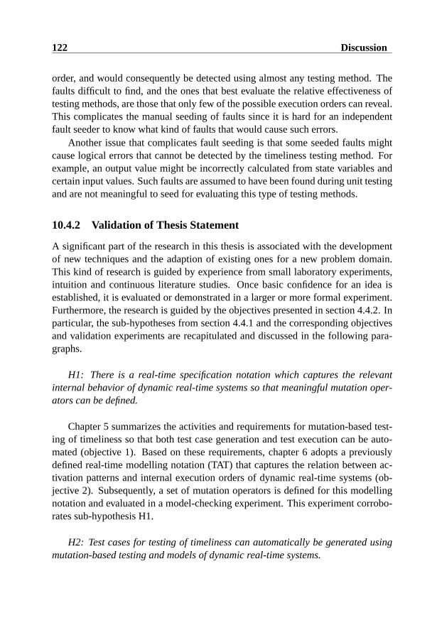
122 Discussion
order, and would consequently be detected using almost any testing method. Thefaults difficult to find, and the ones that best evaluate the relative effectiveness oftesting methods, are those that only few of the possible execution orders can reveal.This complicates the manual seeding of faults since it is hard for an independentfault seeder to know what kind of faults that would cause such errors.
Another issue that complicates fault seeding is that some seeded faults mightcause logical errors that cannot be detected by the timeliness testing method. Forexample, an output value might be incorrectly calculated from state variables andcertain input values. Such faults are assumed to have been found during unit testingand are not meaningful to seed for evaluating this type of testing methods.
10.4.2 Validation of Thesis Statement
A significant part of the research in this thesis is associated with the developmentof new techniques and the adaption of existing ones for a new problem domain.This kind of research is guided by experience from small laboratory experiments,intuition and continuous literature studies. Once basic confidence for an idea isestablished, it is evaluated or demonstrated in a larger or more formal experiment.Furthermore, the research is guided by the objectives presented in section 4.4.2. Inparticular, the sub-hypotheses from section 4.4.1 and the corresponding objectivesand validation experiments are recapitulated and discussed in the following para-graphs.
H1: There is a real-time specification notation which captures the relevantinternal behavior of dynamic real-time systems so that meaningful mutation oper-ators can be defined.
Chapter 5 summarizes the activities and requirements for mutation-based test-ing of timeliness so that both test case generation and test execution can be auto-mated (objective 1). Based on these requirements, chapter 6 adopts a previouslydefined real-time modelling notation (TAT) that captures the relation between ac-tivation patterns and internal execution orders of dynamic real-time systems (ob-jective 2). Subsequently, a set of mutation operators is defined for this modellingnotation and evaluated in a model-checking experiment. This experiment corrobo-rates sub-hypothesis H1.
H2: Test cases for testing of timeliness can automatically be generated usingmutation-based testing and models of dynamic real-time systems.

10.4 Validation of Mutation-based Testing of Timeliness 123
In chapter 6 it is recognized that the same model-checking mechanism used forvalidating the mutation operators can be used for automatically generating timeli-ness test cases. However, since this method has limitations with respect to systemsize and extendability, it is not practical for all types of dynamic real-time sys-tems. Instead, chapter 7 presents another approach for automatically generatingmutation-based test cases using heuristic driven simulations (objective 3). Thismethod is evaluated in three test case generation case studies that corroborate sub-hypothesis H2.
H3: Test cases generated using mutation-based testing are more effective thanrandom test cases for revealing timeliness errors on a realistic target platform.
To perform experiments and support extendability, a prototype tool was de-veloped. The central features in the design of this tool are presented in chapter 8(objective 4). In chapter 9, a case-study is described in which the mutation-basedtesting framework is applied on a small real-time control application (objective 5).The case-study exemplifies how the different activities in the framework can beperformed for a specific target system. It also contain an experiment that givesconfidence in the effectiveness of mutation-based test cases, given that large de-terministic variances in execution patterns are captured during test case generation.Hence, this experiment corroborates sub-hypothesis H3 under the condition that themutation-based test cases are generated using a suitable model of task instances.
Consequently, we conclude that this thesis provides one possible solution ofthe problem outlined in section 4.35. An mutation-based testing method has beenadapted so that it can be used to automatically generate activation patterns thattarget execution orders that are likely to reveal timeliness failures. Since the popu-lation of dynamic real-time systems is unknown (this holds for most types of soft-ware), it is difficult to assess the general applicability of a testing method based onlaboratory experiments and even industrial case studies (the problem is to obtain arepresentative sample). However, the adapted method is defined in the context ofan extendable framework and, hopefully, this will encourage practitioners and re-searchers to apply the method and its associated tool for other platforms and similartesting problems.
5Note that it is possible to negate each of the sub-hypotheses and express the experiment resultsas counter examples. However, we find it more natural to present the sub-hypotheses as statementsin the positive form.

124 Discussion

Chapter 11
Related Work
This chapter presents related work in the joint area of software testing and real-time,reactive systems. The focus is on test case generation but other relevant contribu-tions in the area of testing are also discussed.
11.1 Test Case Generation
This section describes the state-of-the-art methods of generating test cases for real-time systems. In particular, there is a focus on methods that claim to generate testcases for real-time, embedded or reactive systems. Table 11.1 lists the authors ofrelated work and classifies the contributions with respect to three categories. Whenthe same authors have several related publications addressing different aspects ofthe same method, only one is included in the table. The first category (the columndenoted ‘T’) indicates whether the approaches are developed for system level test-ing of time constraints. Generally, such approaches use some formal or structuredmodel for capturing time constraints.
The column denoted ‘I’ indicates if the related work uses information aboutconcurrent tasks, shared resources and real-time protocols for deciding relevant in-puts. In contrast to our approach, few other methods based on formal notationsinclude this in their models (probably to avoid of the associated state space explo-sion). However, if the internal behavior is not modelled, it is generally impossibleto predict the worst case activation pattern for a system that is implemented usingconventional real-time operating systems and task models. For example, exactly
125
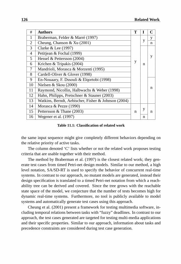
126 Related Work
# Authors T I C1 Braberman, Felder & Marre (1997)
y
yy
2 Cheung, Chanson & Xu (2001) n3 Clarke & Lee (1997)
n
y4 Petitjean & Fochal (1999)5 Hessel & Pettersson (2004)6 Krichen & Tripakis (2004)7 Mandrioli, Morasca & Morzenti (1995)8 Cardell-Oliver & Glover (1998)9 En-Nouaary, F. Dssouli & Elqortobi (1998)
n10 Nielsen & Skou (2000)11 Raymond, Nicollin, Halbwachs & Weber (1998)12 Hahn, Philipps, Pretschner & Stauner (2003)13 Watkins, Berndt, Aebischer, Fisher & Johnson (2004)14 Morasca & Pezze (1990)
ny
n15 Pettersson & Thane (2003)16 Wegener et al. (1997) n
Table 11.1: Classification of related work
the same input sequence might give completely different behaviors depending onthe relative priority of active tasks.
The column denoted ‘C’ lists whether or not the related work proposes testingcriteria that are usable together with their method.
The method by Braberman et al. (1997) is the closest related work; they gen-erate test cases from timed Petri-net design models. Similar to our method, a highlevel notation, SA/SD-RT is used to specify the behavior of concurrent real-timesystems. In contrast to our approach, no mutant models are generated, instead theirdesign specification is translated to a timed Petri-net notation from which a reach-ability tree can be derived and covered. Since the tree grows with the reachablestate space of the model, we conjecture that the number of tests becomes high fordynamic real-time systems. Furthermore, no tool is publicly available to modelsystems and automatically generate test cases using this approach.
Cheung et al. (2001) present a framework for testing multimedia software, in-cluding temporal relations between tasks with “fuzzy” deadlines. In contrast to ourapproach, the test cases generated are targeted for testing multi-media applicationsand their specific properties. Similar to our approach, information about tasks andprecedence constraints are considered during test case generation.
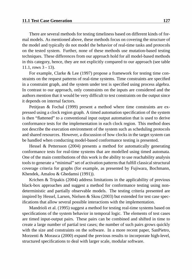
11.1 Test Case Generation 127
There are several methods for testing timeliness based on different kinds of for-mal models. As mentioned above, these methods focus on covering the structure ofthe model and typically do not model the behavior of real-time tasks and protocolson the tested system. Further, none of these methods use mutation-based testingtechniques. These differences from our approach hold for all model-based methodsin this category, hence, they are not explicitly compared to our approach (see table11.1, rows 3 - 13).
For example, Clarke & Lee (1997) propose a framework for testing time con-straints on the request patterns of real-time systems. Time constraints are specifiedin a constraint graph, and the system under test is specified using process algebra.In contrast to our approach, only constraints on the inputs are considered and theauthors mention that it would be very difficult to test constraints on the output sinceit depends on internal factors.
Petitjean & Fochal (1999) present a method where time constraints are ex-pressed using a clock region graph. A timed automation specification of the systemis then “flattened” to a conventional input output automation that is used to deriveconformance tests for the implementation in each clock region. This method doesnot describe the execution environment of the system such as scheduling protocolsand shared resources. However, a discussion of how clocks in the target system canbe handled when conducting model-based conformance testing is presented.
Hessel & Pettersson (2004) presents a method for automatically generatingconformance tests for real-time systems that are modelled using timed automata.One of the main contributions of this work is the ability to use reachability analysistools to generate a “minimal” set of activation patterns that fulfill classical structuralcoverage criteria for graphs (for example, as presented by Fujiwara, Bochmann,Khendek, Amalou & Ghedamsi (1991)).
Krichen & Tripakis (2004) address limitations in the applicability of previousblack-box approaches and suggest a method for conformance testing using non-deterministic and partially observable models. The testing criteria presented areinspired by Hessel, Larsen, Nielsen & Skou (2003) but extended for test case spec-ifications that allow several possible interactions with the implementation.
Mandrioli et al. (1995) suggest a method for testing real-time systems based onspecifications of the system behavior in temporal logic. The elements of test casesare timed input-output pairs. These pairs can be combined and shifted in time tocreate a large number of partial test cases; the number of such pairs grows quicklywith the size and constraints on the software. In a more recent paper, SanPietro,Morzenti & Morasca (2000) expand the previous results to incorporate high-level,structured specifications to deal with larger scale, modular software.
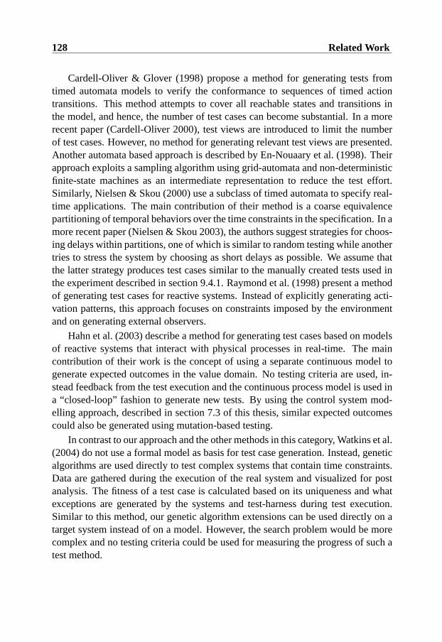
128 Related Work
Cardell-Oliver & Glover (1998) propose a method for generating tests fromtimed automata models to verify the conformance to sequences of timed actiontransitions. This method attempts to cover all reachable states and transitions inthe model, and hence, the number of test cases can become substantial. In a morerecent paper (Cardell-Oliver 2000), test views are introduced to limit the numberof test cases. However, no method for generating relevant test views are presented.Another automata based approach is described by En-Nouaary et al. (1998). Theirapproach exploits a sampling algorithm using grid-automata and non-deterministicfinite-state machines as an intermediate representation to reduce the test effort.Similarly, Nielsen & Skou (2000) use a subclass of timed automata to specify real-time applications. The main contribution of their method is a coarse equivalencepartitioning of temporal behaviors over the time constraints in the specification. In amore recent paper (Nielsen & Skou 2003), the authors suggest strategies for choos-ing delays within partitions, one of which is similar to random testing while anothertries to stress the system by choosing as short delays as possible. We assume thatthe latter strategy produces test cases similar to the manually created tests used inthe experiment described in section 9.4.1. Raymond et al. (1998) present a methodof generating test cases for reactive systems. Instead of explicitly generating acti-vation patterns, this approach focuses on constraints imposed by the environmentand on generating external observers.
Hahn et al. (2003) describe a method for generating test cases based on modelsof reactive systems that interact with physical processes in real-time. The maincontribution of their work is the concept of using a separate continuous model togenerate expected outcomes in the value domain. No testing criteria are used, in-stead feedback from the test execution and the continuous process model is used ina “closed-loop” fashion to generate new tests. By using the control system mod-elling approach, described in section 7.3 of this thesis, similar expected outcomescould also be generated using mutation-based testing.
In contrast to our approach and the other methods in this category, Watkins et al.(2004) do not use a formal model as basis for test case generation. Instead, geneticalgorithms are used directly to test complex systems that contain time constraints.Data are gathered during the execution of the real system and visualized for postanalysis. The fitness of a test case is calculated based on its uniqueness and whatexceptions are generated by the systems and test-harness during test execution.Similar to this method, our genetic algorithm extensions can be used directly on atarget system instead of on a model. However, the search problem would be morecomplex and no testing criteria could be used for measuring the progress of such atest method.

11.2 Testing of Real-Time Systems 129
There is some related methods, not developed for system-level testing of time-liness, that nevertheless are relevant or complementary to our approach (see table11.1, rows 14 - 16).
Morasca & Pezze (1990) propose a method for testing concurrent and real-timesystems that uses high-level Petri-nets for specification and implementation. Thismethod does not explicitly handle timeliness, nor does it provide testing criteria,but it is one of the first to model the internal concurrency of the tested real-timesystem using Petri-nets.
Thane (2000) proposes a method to derive execution orders of a real-time sys-tem before it is put into operation. It was suggested that each execution order canbe treated as a sequential program where conventional test methods can be applied.During test execution, the tests are sorted according to the pre-analyzed executionorders. In a more recent paper, Pettersson and Thane (Pettersson & Thane 2003)extend the method by supporting shared resources. In contrast to our method, thismethod is developed for real-time systems where all task activation times are knownat design time.
Wegener et al. use genetic algorithms to test temporal properties of real-timetasks (Wegener et al. 1997). However, the main focus of their work is determiningsuitable inputs for producing worst and best-case execution times. This approachis a valuable complement to our method, since we assume that relevant classes ofinput data exist for each real-time task before system-level testing of timelinessstarts.
11.2 Testing of Real-Time Systems
Thane (2000) presents results for testing and debugging distributed real-time sys-tems. As previously mentioned, Thane focuses on statically scheduled systemswhere it is tractable to analyze the possible execution orders before the system goesinto operation. The system is then executed until there is enough test coverage ofeach of the anticipated execution orders. Thane does not present any method forgenerating timeliness test cases or relevant execution orders; instead he suggeststhat conventional methods can be used in combination with his execution orderanalysis. Thane also proposes a method for deterministic replay and debuggingfacilities for real-time systems. Both the non-deterministic test execution approachand the replay and debugging facilities are useful complements to the testing frame-work presented in this thesis.
Although the focus of Schutz’s (Schutz 1993) work is on testing time-triggered
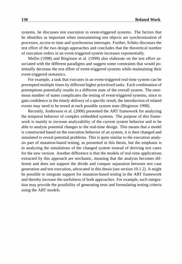
130 Related Work
systems, he discusses test execution in event-triggered systems. The factors thathe identifies as important when instrumenting test objects are synchronization ofprocesses, access to time and synchronous interrupts. Further, Schutz discusses thetest effort of the two design approaches and concludes that the theoretical numberof execution orders in an event-triggered system increases exponentially.
Mellin (1998) and Birgisson et al. (1999) also elaborate on the test effort as-sociated with the different paradigms and suggest some constraints that would po-tentially decrease the test effort of event-triggered systems while maintaining theirevent-triggered semantics.
For example, a task that executes in an event-triggered real-time system can bepreempted multiple times by different higher prioritized tasks. Each combination ofpreemptions potentially results in a different state of the overall system. The enor-mous number of states complicates the testing of event-triggered systems, since togain confidence in the timely delivery of a specific result, the introduction of relatedevents may need to be tested at each possible system state (Birgisson 1998).
Recently, Andersson et al. (2006) presented the ART framework for analyzingthe temporal behavior of complex embedded systems. The purpose of this frame-work is mainly to increase analyzability of the current system behavior and to beable to analyze potential changes to the real-time design. This means that a modelis constructed based on the execution behavior of an system, it is then changed andsimulated to reveal potential problems. This is quite similar to the execution analy-sis part of mutation-based testing, as presented in this thesis, but the emphasis isin analyzing the simulations of the changed system instead of deriving test casesfor the new version. Another difference is that the models of real-time applicationsextracted by this approach are stochastic, meaning that the analysis becomes dif-ferent and does not support the divide and conquer separation between test casegeneration and test execution, advocated in this thesis (see section 10.1.2). It mightbe possible to integrate support for mutation-based testing in the ART frameworkand thereby increase the usefulness of both approaches. For example, such integra-tion may provide the possibility of generating tests and formulating testing criteriausing the ART models.
Chapter 12
Conclusions
This chapter summarizes this thesis and elaborates on the impact of the results andcontributions. Future directions for research on this topic are also suggested.
12.1 Summary
Timeliness is a property that is unique for real-time systems and deserves specialconsideration during both design and testing. A problem when testing timelinessof dynamic real-time systems is that response times depend on the execution orderof concurrent tasks. Other existing testing methods ignore task interleaving andtiming and, thus, do not help determine what kind of test cases are meaningful fortesting timeliness. This thesis presents several contributions for automated testingof timeliness for dynamic real-time systems. In particular, a model-based testingmethod, founded in mutation testing theory, is proposed and evaluated for reveal-ing failures arising from timeliness faults. One contribution in this context is thatmutation-based testing and models developed for generic schedulabilty analysis,can be used to express testing criteria for timeliness and for automatic generationof mutation-based test cases. Seven basic mutation operators are formally definedand validated to represent error types that can lead to timeliness failures. Theseoperators can subsequently be used to set up relevant testing criteria.
Two approaches for automatically generating test cases for timeliness are de-fined. One approach reliably generates test cases that can distinguish a correct sys-tem from a system with a hypothesized timeliness error. The second approach is
131
132 Conclusions
designed to be extendible for many target platforms and has the potential to gener-ate test cases that target errors in the interaction between real-time control systemsand physical processes, modelled in MATLAB/Simulink. In addition, this thesisoutlines a scheme for prefix-based test case execution and describes how such amethod can exploit the information from mutation-based test case generation tofocus testing on the most relevant scenarios.
The contributions outlined above are put into context by a framework for au-tomated testing of timeliness. This framework specifies activities, techniques andimportant issues for conducting mutation-based timeliness testing – from systemmodelling to automated test case execution.
The validation of the proposed testing approaches is done iteratively throughcase studies and proof-of-concept implementations. In particular, the mutation-based testing criteria are validated through a model-checking case study (see sec-tion 6.6). This case study reveals that the generated mutants actually lead to time-liness violations in a simple real-time system model. The simulation based testcase generation method is evaluated in a set of test case generation experimentswith different target system characteristics (see section 7.4). These experimentsindicate that the approach is applicable for generating test cases for non-trivial dy-namic real-time systems and real-time control systems with mixed task loads. Thiswas not possible using previously existing methods due to problems with the sizeof the reachable state space and limitations in tool support. Finally, the proposedframework for testing of timeliness is demonstrated on a small robot control appli-cation running on Linux/RTAI. This case study indicates that the mutation-basedtest cases, that are generated using assumptions of the internal structure of the real-time system, can be more effective than both naively constructed stress tests and asuite of randomly generated test cases that are approximately ten times larger.
Consequently, our case studies and experiments corroborate the hypothesis pre-sented in section4.4.1. Mutation-based testing can be used for generating effectivetest cases by exploiting models that take internal behaviors into consideration.
12.2 Contributions
This section briefly summarizes the contributions of this thesis. The contributionsare the result of pursuing the objectives outlined in section 4.4.2.
• A mutation-based framework for testing of timeliness. The framework isconstructed to address the problems summarized in chapter 4 and is demon-

12.3 Future Work 133
strated to be effective in finding timeliness errors in dynamic real-time sys-tems.
• An extendible set of mutation operators defined in terms of a modelling no-tation which captures varying execution orders. This kind of mutation oper-ators allows coverage to be expressed when testing timeliness.
• A method for automatically generating mutation-based test cases for timeli-ness using model checking.
• A method for automatically generating mutation-based test cases for timeli-ness using heuristic driven simulations.
• A tool prototype that allows automated test case generation according to theproposed framework and supports modelling of the environment using MAT-LAB/Simulink.
A part from these contributions, this thesis contains an example of how theproposed framework can be applied for testing a simple robot arm control system.Also, a scheme for pre-fix based test execution, that increases controllability and iscompatible with the mutation-based framework, is outlined.
12.3 Future Work
This section contains some spin-off ideas of how the framework for automatic test-ing of timeliness can be extended beyond the scope of this work.
Field-study on Framework Applicability
The framework presented in this thesis has been shown effective using a combina-tion of simulation, proof-of-concept and a limited feasibility case-study. To furthervalidate the applicability and flexibility of the presented framework it is desirableto use it to test a wide range of commercial real-time applications. This kind ofstudy would reveal how well the proposed framework can be adapted for platformsand applications used in commercial real-time system development. Furthermore,it would be interesting to compare the effectiveness of ad-hoc methods used inindustry with our framework.
134 Conclusions
Testing of Timeliness during Mode-changes
The testing experiments presented in this thesis have focused on testing the time-liness of a real-time system from startup. This assumes that the system and itsenvironment continues to operate in a similar way during the rest of its execution.However, for some systems the mode of operation may change at certain pointsin time. This means that the system task set are altered or that different types ofservices is requested or become more critical. A typical example of this is a controlsystem on an aircraft, where there is one mode of operation when the aircraft istaxiing on the ground, and another when the plane is airborne. In these kinds ofsystems it may be important that some services remain timely during the transitionfrom one mode of operation to another. The testing framework presented in thisthesis should be evaluated for generating timeliness test cases during the transitionfrom one mode to the other. We believe that such extension is possible and canincrease the usefulness of the timeliness testing framework even more.
Testing of Timeliness for Multi-Processor Systems
A emerging trend in general computing is to increase performance by utilizing par-allel processors and specialized computing elements (for example, chips containingfield programmable gate arrays). Eventually, this trend will force developers to useparallel platforms for dependable real-time applications.
Unfortunately, the problems motivating a structured and generalizable approachfor testing of timeliness are even more prevalent in architectures with several activeprocessing units. In particular, the relation between activation patterns and exe-cution orders is more complex and the problems associated with finding criticalscenarios are elevated.
The framework presented in this thesis has currently only been evaluated forsingle processor architectures. However, assuming that the scheduling protocolin a multiprocessor system behave deterministically given a specified task set andactivation pattern, it may be possible to use the proposed methods and tools totest timeliness of a multi-processor system. Consequently, the divide and conquerapproach provided by the combination of mutation testing, execution order analysisand non-deterministic test execution should be evaluated for this domain. An initialfuture work along this line is to perform a series of test case generation experimentsusing a simulated multiprocessor platform.
12.3 Future Work 135
Evaluation of the Iterative Delta Reduction Mode
During initial experimentation with the different test case generation modes (de-scribed in section 8.3), it was observed that, for some system models, the iterativedelta reduction mode killed mutants with small deltas more reliably than usingthe fixed delta mode directly. However, it is still inconclusive wether the iterativetightening of deltas actually improve the capabilities of the heuristic search or ifthis effect only is a consequence of running more simulations. A series of con-trolled experiments would be needed to investigate this. Furthermore, we leave as afuture work to determine if the hybrid test suites generated using the iterative deltareduction mode can be as effective as the test suites generated using fixed deltas.
Validation of the Prefix-based Test Execution Scheme
The prefix-based test execution approach outlined in section 10.3.2 generally re-quires support from the test harness and from the operating system where a real-time application is run. Despite indications that designated pre-emption pointsincrease the controllability of dynamic real-time systems, it is still unclear whatpenalties are associated with including them in real-time systems. An interestingproject would be to integrate the prefix-based test execution scheme with a real-timeoperating system and compare the effort to observe a particular execution order.
A partial implementation of designated pre-emption points has been made onthe RTAI platform using a globally shared semaphore (execution token) that is tem-porarily released and re-taken when certain system calls are issued or when specificpoints in the task code are reached. During the state enforcement phase a high pri-ority “enforcer task” is used for reading the prefix-description and waking up appli-cation tasks in a specified order. A structured experiment is needed to determine ifthis implementation of the prefix-based test execution scheme can be used withouta probe effect.
A Testable Platform for Dynamic Real-time Systems
Even if the testing framework presented in this thesis is developed to be generaland adaptable for many platforms, there are potential benefits in standardizing thetarget system platform. For example, by providing a suite of tools for applicationmodelling, mutation-based test generation, predictable event monitoring and prefixbased test execution for a specific platform, real-time application developers cantry both the methods and the platform directly.
136 Conclusions
One candidate platform for event-triggered real time applications is the Dis-tributed activE real-timE Database System – DeeDS. The DeeDS prototype alreadycontains predictable event monitoring, transaction support and real-time schedulingprotocols. However, it is important that the real-time properties of such a platformare evaluated experimentally and captured in an accurate execution environmentmodel.
Evidence-based online monitoring
The test case experiments presented in this thesis indicate that the tasks’ specifiedworst case execution behavior often can be violated without jeopardizing systemlevel timeliness.
Malignant mutants contain cases where such violations can lead to problems.Using execution order analysis of malignant mutants, it is possible to characterizesituations where timeliness failures may occur. From this it might be possible toautomatically create composite event descriptions that can trigger on sequencesof events leading up to a situation where a system level time constraint might beviolated. This could be used to predict dangerous situations before they occur andprevent errors leading to timeliness failures.

References
Alur, R. & Dill, D. (1994), ‘A theory of timed automata’,Theoretical ComputerScience126, 183–235.
Ammann, P. & Black, P. (1999), A specification-based coverage metric to evaluatetest sets,in ‘HASE ’99: Proceedings of the 4th IEEE International Sympo-sium on High-Assurance Systems’, Washington, DC, pp. 239–248.
Ammann, P., Black, P. & Majurski., W. (1998), Using model checking to gen-erate tests from specifications,in ‘Proceedings of the Second IEEE Interna-tional Conference on Formal Engineering Methods’, IEEE Computer Society,pp. 46–54.
Ammann, P., Ding, W. & Xu, D. (2001), Using a model checker to test safety prop-erties,in ‘Proccedings of the Seventh IEEE International Conference on En-gineering of Complex Computer Systems’, IEEE Computer Society, Skovde,Sweden, pp. 212–221.
Ammann, P. & Offutt, J. (1994), Using formal methods to derive test frames incategory-partiton testing,in ‘Proceedings of the Ninth Annual Conference onComputer Assurance (COMPASS 94)’, pp. 69–80.
Amnell, T., Fersman, E., Mokrushin, L., Pettersson, P. & Yi, W. (2002), Times - Atool for modelling and implementation of embedded systems,in ‘Proceedingsof TACAS’02’, number 2280, Springer–Verlag, pp. 460–464.
Andersson, J., Wall, A. & Norstrom, C. (2006), A framework for analysis of tim-ing and resource utilization targeting complex embedded systems, UppsalaUniversity, pp. 297–329.
137

138 References
Andrews, J. H., Briand, L. C. & Labiche, Y. (2005), Is mutation an appropriate toolfor testing experiments?,in ‘Proceedings of the 27th IEEE International Con-ference on Software Engineering (ICSE 2005)’, St. Louis, Missouri, pp. 402–411.
Astrom, K. J. & Wittenmark, B. (1997),Computer-Controlled Systems, PrenticeHall.
Baker, T. P. (1991), ‘Stack-based scheduling of real-time processes’,The Journalof Real-Time Systems(3), 67–99.
Beizer, B. (1990),Software Testing Techniques, Von Nostrand Reinhold.
Berkenkotter, K. & Kirner, R. (2005), Real-time and hybrid systems testing,inM. Broy, B. Jonsson, J.-P. Katoen, M. Leucker & A. Pretschner, eds, ‘Model-based testing of Reactive Systems’, Vol. LNCS, Springer-Verlag, pp. 355–387.
Bianchi, E., Dozio, L., Ghiringhelli, G. & Mantegazza, P. (1999), Complex controlsystems, applications of diapm-rtai at diapm,in ‘Realtime Linux Workshop’,Vienna.
Birgisson, R. (1998), Improving testability of applications in acitve real-time data-base environments, Master’s thesis, University of Skovde. HS-IDA-MD-98-001.
Birgisson, R., Mellin, J. & Andler, S. F. (1999), Bounds on test effort for event-triggered real-time systems,in ‘Proceedings ot the 6th International Con-ference on Real-Time Computing, Systems and Applications (RTCSA’99)’,IEEE Computer Society Press, Hong-Kong, pp. 212–215.
Bowen, J. P. & Hinchey, M. G. (1995), ‘Seven more myths of formal methods’,IEEE Software12(4), 34–41.
Braberman, V., Felder, M. & Marre, M. (1997), Testing timing behavior of real-time software,in ‘International Software Quality Week’.
Burns & Wellings (2001),Real-Time Systems and Programming Languages, Addi-son Wesley.
Cardell-Oliver, R. (2000), ‘Conformance tests for real-time systems with timedautomata specifications’,Formal Aspects of Computing12(5), 350–371.
References 139
Cardell-Oliver, R. & Glover, T. (1998), ‘A practical and complete algorithm fortesting real-time systems’,Lecture Notes in Computer Science1486, 251–261.
Cheung, S. C., Chanson, S. T. & Xu, Z. (2001), Toward generic timing tests for dis-tributed multimedia software systems,in ‘ISSRE ’01: Proceedings of the 12thInternational Symposium on Software Reliability Engineering (ISSRE’01)’,IEEE Computer Society, Washington, DC, USA, p. 210.
Chevalley, P. & Thevenod-Fosse, P. (2002), ‘A mutation analysis tool for java pro-grams’,Software Tools and for Technology Transferpp. 1–14.
Clarke, D. & Lee, I. (1997), Automatic generation of tests for timing constraintsfrom requirements,in ‘Proceedings of the Third International Workshop onObject-Oriented Real-Time Dependable Systems’, Newport Beach, Califor-nia.
Dahl, O., Dijikstra, E. W. & Hoare, C. (1972),Structured Programming.
DeMillo, R. A., Lipton, R. J. & Sayward, F. G. (1978), ‘Hints on test data selection:Help for the practicing programmer’,IEEE Computer11(4), 34–41.
DeMillo, R. A. & Offutt, A. J. (1991), ‘Constraint-based automatic test data gener-ation’, Transactions on Software EngineeringSE-17(9), 900–910.
DeMillo, R. A. & Offutt, A. J. (1993), ‘Exprimental results from an automatic testcase generator’,ACM Transactions on Software Engineering and Methodol-ogy.
En-Nouaary, R., F. Dssouli, K. & Elqortobi, A. (1998), Timed test case generationbased on a state characterization technique,in ‘Proceeding of the 19th IEEEReal-Time Systems Symposium (RTSS98)’, Madrid, Spain.
Fersman, E. (2003), A Generic Approach to Schedulability Analysis of Real-TimeSystems, PhD thesis, University of Uppsala, Faculty of Science and Technol-ogy.
Fersman, E., Pettersson, P. & Yi, W. (2002), Timed automata with asynchronousprocesses: Schedulability and decidability,in J.-P. Katoen & P. Stevens, eds,‘Proc. of the 8th International Conference on Tools and Algorithms for theConstruction and Analysis of Systems’, number 2280in ‘Lecture Notes inComputer Science’, Springer–Verlag, pp. 67–82.

140 References
Fujiwara, S., Bochmann, G. V., Khendek, F., Amalou, M. & Ghedamsi, A. (1991),‘Test selection based on finite state models’,IEEE Transactions on softwareengineering17(6), 591–603.
Gait, J. (1986), ‘A probe effect in concurrent programs’,Software - Practice andExperience16(3), 225–233.
Gamma, E., Helm, R., Johnson, R. & Vlissides, J. (1994),Design Patterns: Ele-ments of Reusable Object-Oriented Software., Addison-Wesley.
Gray, J. & Reuter, A. (1993),Transaction Processing, Concepts and Techniques,Morgan Kaufmann.
Hahn, G., Philipps, J., Pretschner, A. & Stauner, T. (2003), ‘Prototype-based testsfor hybrid reactive systems’,14th IEEE International Workshop on RapidSystem Prototyping00, 78.
Hansson, J., Son, S., Stankovic, J. & Andler, S. (1998), Dynamic transactionscheduling and reallocation in overloaded real-time database systems,in ‘Pro-ceedings of the 5th International Conference on Real-Time Computing Sys-tems and Applications’.
Henriksson, D. (2006), Resource-Constrained Embedded Control and ComputingSystems, PhD thesis, Department of Automatic Control, Lund University.
Henriksson, D., Cervin, A. &Arzen, K.-E. (2003), TrueTime: Real-time controlsystem simulation with MATLAB/Simulink,in ‘Proceedings of the NordicMATLAB Conference’, Copenhagen, Denmark.
Hessel, A., Larsen, K., Nielsen, B. & Skou, A. (2003), Time optimal real-timetest case generation using UPPAAL,in ‘Proceedings of Workshop on FormalApproaches to Testing of Software (FATES)’, Montreal.
Hessel, A. & Pettersson, P. (2004), A test case generation algorithm for real-timesystems,in ‘Proceedings of the Fourth International Conference on QualitySoftware’, pp. 268– 273.
Houck, C., Joines, J. & Kay, M. (1995), A genetic algorithm for function opti-mization: A Matlab implementation, Technical Report NCSU-IE TR 95-09,Department of Computer Science, North Carolina State University.

References 141
Hwang, G., Tai, K. & Hunag, T. (1995), ‘Reachability testing : An approach totesting concurrent software’,International Journal of Software Engineeringand Knowledge Engineering5(4).
Kim, S., Clark, J. & McDermid, J. (2000), Class mutation: Mutation testingfor object-oriented programs,in ‘Net.ObjectDays Conference on Object-Oriented Software Systems’.
Kopetz, H., Zainlinger, R., Fohler, G., Kantz, H., Puschner, P. & Schutz, W.(1991), An engineering approach to hard real-time system design,in ‘Pro-ceedings of the Third European Software Engineering Conference’, Milano,Italy, pp. 166–188.
Krichen, M. & Tripakis, S. (2004), Black-box conformance testing for real-timesystems,in ‘Proceecings of SPIN’04 Workshop on Model-Checking Soft-ware’.
Laprie, J., ed. (1994),Dependability: Basic Concepts and Terminology, Springer-Verlag for IFIP WG 10.4.
Larsen, K. G., Pettersson, P. & Yi, W. (1995), Compositional and symbolic model-checking of real-time systems,in ‘IEEE Real-time Systems Symposium’,pp. 76–89.
Liu, C. L. & Layland, J. W. (1973), ‘Scheduling algorithms for multiprogrammingin a hard-real-time environment’,Journal of the ACM20(1), 46–61.
Ma, Y. S., Offutt, A. J. & Kwon, Y. R. (2005), ‘Mujava: An automated class muta-tion system’,Software Testing, Verification and Reliabilty2(15), 97–133.
Mandrioli, D., Morasca, S. & Morzenti, A. (1995), ‘Generating test cases for real-time systems from logic specifications’,ACM Transactions on Computer Sys-tems4(13), 365–398.
Mellin, J. (1998), Supporting system level testing of applications by active real-time databases,in ‘Proceedings 2nd International Workshop on Active,Real-Time, and Temporal Databases, ARTDB-97, number 1553 in LNCS.Springer-Verlag.’.
Michalewicz, Z. & Fogel, D. B. (1998),How to solve it : Modern Heuristics,Springer.
142 References
Morasca, S. & Pezze, M. (1990), ‘Using high level Petri-nets for testing concur-rent and real-time systems’,Real-Time Systems: Theory and Applicationspp. 119–131. Amsterdam North-Holland.
Nielsen, B. & Skou, A. (2000), Automated test generation from timed automata,in‘Proceedings of the 21st IEEE Real-Time Systems Symposium’, IEEE, WaltDisney World, Orlando, Florida.
Nielsen, B. & Skou, A. (2003), ‘Automated test generation from timed automata’,International Journal on Software Tools for Technology Transfer (STTT)5(1), 59 – 77.
Nilsson, K. (2005), Personal communication.
Nilsson, R. (2000), Automated selective test case generation methods for real-timesystems, Master’s thesis, University of Skovde.
Nilsson, R. (2003), Thesis proposal : Automated timeliness testing of dynamic real-time systems, Technical Report HS-IDA-TR-03-006, School of Humanitiesand Informatics, Univeristiy of Skovde.
Nilsson, R., Andler, S. & Mellin, J. (2002), Towards a Framework for AutomatedTesting of Transaction-Based Real-Time Systems,in ‘Proceedings of EigthInternational Conference on Real-Time Computing Systems and Applications(RTCSA2002)’, Tokyo, Japan, pp. 109–113.
Nilsson, R. & Henriksson, D. (2005), Test case generation for flexible real-timecontrol systems,in ‘Proceedings of the 10th IEEE International Conferenceon Emerging Technologies and Factory Automation’, Catania, Italy, pp. 723–731.
Nilsson, R., Offutt, J. & Andler, S. F. (2004), Mutation-based testing criteria fortimeliness,in ‘Proceedings of the 28th Annual Computer Software and Ap-plications Conference (COMPSAC)’, IEEE Computer Society, Hong Kong,pp. 306–312.
Nilsson, R., Offutt, J. & Mellin, J. (2006), Test case generation for mutation-basedtesting of timeliness,in ‘Proceedings of the 2nd International Workshop onModel Based Testing’, pp. 102–121.
Norstrom, C., A.Wall & Yi, W. (1999), Timed automata as task models for event-driven systems,in ‘Proceedings of RTCSA’99’, Hong Kong.
References 143
Offutt, A. J., Xiong, Y. & Liu, S. (1999), Criteria for generating specification-basedtests,in ‘Proceedings of the fifth International Conference on Engineering ofComplex Computer Systems’, Las Vegas.
Offutt, J., Alexander, R., Y.Wu, Xiao, Q. & Hutchinson, C. (2001), A fault modelfor sub-type inheritance and polymorphism,in ‘Proceedings pf the 12th Inter-national Symposium on Software Reliability Engineering’, IEEE ComputerSociety Press, Hong Kong China, pp. 84–93.
Offutt, J., Jin, Z. & Pan, J. (1999), ‘The dynamic domain reduction approach to testdata generation’,Software–Practice and Experience29(2), 167–193.
Offutt, J., Ma, Y.-S. & Kwon, Y.-R. (2006), The class-level mutants of mujava,in‘Workshop on Automation of Software Test (AST 2006)’, Shanghai, China,pp. 78–84.
Petitjean, E. & Fochal, H. (1999), A realistic architecture for timed testing,in ‘Proc.of Fifth IEEE International Conference on Engineering of Complex ComputerSystems’, USA, Las Vegas.
Petters, S. M. & Farber, G. (1999), Making worst case execution time analy-sis for hard real-time tasks on state of the art processors feasible,in ‘Proc.6th Int’l Conference on Real-Time Computing, Systems and Applications(RTCSA’99)’, Hong Kong.
Pettersson, A. & Thane, H. (2003), Testing of multi-tasking real-time systems withcritical sections,in ‘Proceedings of Ninth International Conference on Real-Time Computing Systems and Applications (RTCSA’03)’, Tainan city, Tai-wan.
Puschner, P. P. & Schedl, A. V. (1991), ‘Computing maximum task execution times- a graph based approach’. Kluwer Academic Publishers, Boston. Manufac-tured in The Netherlands.
Ramamritham, K. (1995), The origin of time constraints,in M. Berndtsson &J. Hansson, eds, ‘Proceedings of the First International Workshop on Activeand Real-Time Database Systems (ARTDB 1995)’, Springer, Skovde, Swe-den, pp. 50–62.
Raymond, P., Nicollin, X., Halbwachs, N. & Weber, D. (1998), Automatic test-ing of reactive systems,in ‘Proceeding of the 19th IEEE Real-Time SystemsSymposium (RTSS98)’.
144 References
Rothermel, G. & Harrold, M. J. (1997), ‘A safe, efficient regression test selectiontechnique’.
SanPietro, P., Morzenti, A. & Morasca, S. (2000), ‘Generation of execution se-quences for modular time critical systems’,IEEE Transactions on SoftwareEngineering26(2), 128–149.
Schutz, W. (1993),The Testability of Distributed Real-Time Systems, Kluwer Aca-demic Publishers.
Schutz, W. (1994), ‘Fundamental issues in testing distributed real-time systems’,Real-Time Systems7(2), 129–157.
Sha, L., Rajkumar, R. & Lehczky, J. P. (1990), ‘Priority inheritance protocols:An approach to real-time synchronization’,IEEE Transactions on Comput-ers9(39), 1175–1185.
Stankovic, J. A., Spuri, M., Ramamritham, K. & Buttazzo, G. C. (1998),Deadlinescheduling for real-time systems, Kluwer academic publishers.
Stankovic, J., Spuri, M., Di Natale, M. & Buttazzo, G. (1995), ‘Implications ofclassical scheduling results for real-time systems’,IEEE Computer28(6), 16–25.
Thane, H. (2000), Monitoring, Testing and Debugging of Distributed Real-TimeSystems, PhD thesis, Royal Institute of Technology. KTH, Stockholm, Swe-den.
Watkins, A., Berndt, D., Aebischer, K., Fisher, J. & Johnson, L. (2004), Breedingsoftware test cases for complex systems,in ‘HICSS ’04: Proceedings of theProceedings of the 37th Annual Hawaii International Conference on SystemSciences (HICSS’04) - Track 9’, IEEE Computer Society, Washington, DC,USA, p. 90303.3.
Wegener, J., StHammer, H. H., Jones, B. F. & Eyres, D. E. (1997), ‘Testing real-time systems using genetic algorithms’,Software Quality Journal6(2), 127–135.
Young, S. J. (1982),Real-Time Languages: Design and Development, Chichester:Ellis Horwood.

Appendix A
Demonstrator Task Code
This appendix describes the implementation of the different tasks that realize therobot application. The purpose of this is primarily to show examples of the applica-tion code to increase the understanding of the tested application and its properties.The current implementation of the robot application is small, consisting of approx-imately 1000 lines of c code. This allows short response-times and high samplingrates. The following subsections describe the implementation of each of the appli-cation tasks.
TrajectoryMgr Task
As outlined in section 9.2 the trajectory manager (TrajectoryMgr) is responsiblefor responding to requests from users or higher level control applications on othernodes. For example, another node can send a sequence of viapoints for movingthe robot hand from position A to position B without smashing into an object orbreaking some rigid object attached to the robot hand (such as the beam in theFlexcon application). The commands that can be issued to the trajectory managertask is;
• Add a trajectory point
• Adjust current trajectory
• Adjust a trajectory point
145
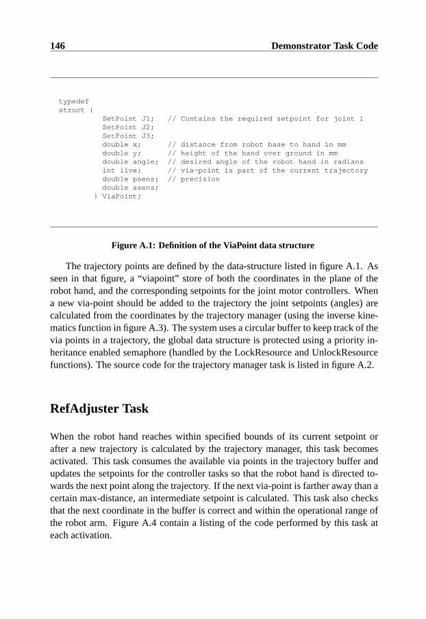
146 Demonstrator Task Code
typedefstruct {
SetPoint J1; // Contains the required setpoint for joint 1SetPoint J2;SetPoint J3;double x; // distance from robot base to hand in mmdouble y; // height of the hand over ground in mmdouble angle; // desired angle of the robot hand in radiansint live; // via-point is part of the current trajectorydouble psens; // precisiondouble asens;
} ViaPoint;
Figure A.1: Definition of the ViaPoint data structure
The trajectory points are defined by the data-structure listed in figure A.1. Asseen in that figure, a “viapoint” store of both the coordinates in the plane of therobot hand, and the corresponding setpoints for the joint motor controllers. Whena new via-point should be added to the trajectory the joint setpoints (angles) arecalculated from the coordinates by the trajectory manager (using the inverse kine-matics function in figure A.3). The system uses a circular buffer to keep track of thevia points in a trajectory, the global data structure is protected using a priority in-heritance enabled semaphore (handled by the LockResource and UnlockResourcefunctions). The source code for the trajectory manager task is listed in figure A.2.
RefAdjuster Task
When the robot hand reaches within specified bounds of its current setpoint orafter a new trajectory is calculated by the trajectory manager, this task becomesactivated. This task consumes the available via points in the trajectory buffer andupdates the setpoints for the controller tasks so that the robot hand is directed to-wards the next point along the trajectory. If the next via-point is farther away than acertain max-distance, an intermediate setpoint is calculated. This task also checksthat the next coordinate in the buffer is correct and within the operational range ofthe robot arm. Figure A.4 contain a listing of the code performed by this task ateach activation.

147
void SPT0_work(SPT0_data * TD,int MyID){LockResource(NETWORK,MyID); // Lock network for reading dataSPT0_inputs IN;ReadNetworkBuffer(&IN);UnlockResource(NETWORK,MyID);LockResource(TRAJBUF,MyID); // lock trajectory-bufferif (IN.operation==ADD){ // Add coordinate
ViaPoint tmp;tmp=InverseKinematics(IN.x,IN.y,IN.angle);// Calculate angles corresponding to coordinatetmp=CorrectCoordinate(tmp); // Check and move..Trajectory[TCurrentP]=tmp;Trajectory[TCurrentP].live=1;int next=TCurrentP+1;if (next>=CBUFFERSIZE) next=0;if (Trajectory[next].live==0){
TCurrentP=next;} else {
// commandbuffer overflow !! Perform error handling}
} else if (IN.operation==ADJUSTALL){ // Move current Trajectoryint i;for(i=0; i<CBUFFERSIZE;i++){
ViaPoint TVP;TVP=Trajectory[i];if (TVP.live==1){
ViaPoint tmp;tmp=InverseKinematics(TVP.x+IN.x,TVP.y+IN.y,TVP.angle+IN.angle);tmp=CorrectCoordinate(tmp);Trajectory[i]=tmp;
}}
} else if (IN.operation==ADJUSTONE) { //Move single Via-point;int Cindex=TCurrentP-IN.index;if (Cindex<0) Cindex=Cindex+CBUFFERSIZE;if (Cindex>=0 && Cindex<CBUFFERSIZE){
if (Trajectory[Cindex].live==1){ViaPoint TVP=Trajectory[Cindex];ViaPoint tmp;tmp=InverseKinematics(TVP.x+IN.x,TVP.y+IN.y,TVP.angle+IN.angle);tmp=CorrectCoordinate(tmp);Trajectory[Cindex]=tmp;
}}
}UnlockResource(TRAJBUF,MyID);
}
Figure A.2: Source code for trajectory manager task
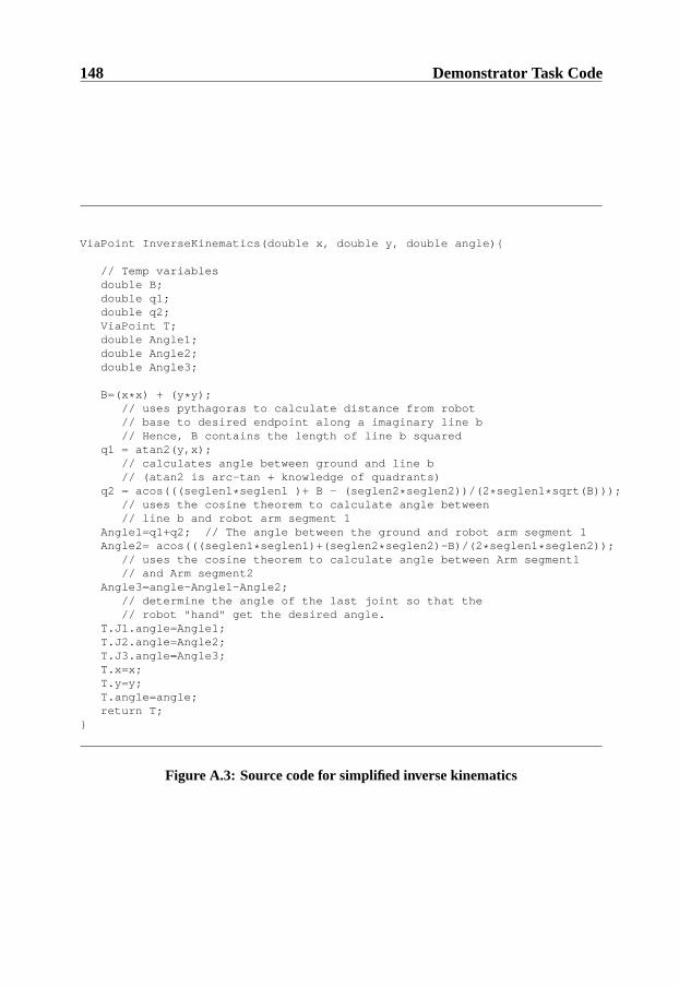
148 Demonstrator Task Code
ViaPoint InverseKinematics(double x, double y, double angle){
// Temp variablesdouble B;double q1;double q2;ViaPoint T;double Angle1;double Angle2;double Angle3;
B=(x * x) + (y * y);// uses pythagoras to calculate distance from robot// base to desired endpoint along a imaginary line b// Hence, B contains the length of line b squared
q1 = atan2(y,x);// calculates angle between ground and line b// (atan2 is arc-tan + knowledge of quadrants)
q2 = acos(((seglen1 * seglen1 )+ B - (seglen2 * seglen2))/(2 * seglen1 * sqrt(B)));// uses the cosine theorem to calculate angle between// line b and robot arm segment 1
Angle1=q1+q2; // The angle between the ground and robot arm segment 1Angle2= acos(((seglen1 * seglen1)+(seglen2 * seglen2)-B)/(2 * seglen1 * seglen2));
// uses the cosine theorem to calculate angle between Arm segment1// and Arm segment2
Angle3=angle-Angle1-Angle2;// determine the angle of the last joint so that the// robot "hand" get the desired angle.
T.J1.angle=Angle1;T.J2.angle=Angle2;T.J3.angle=Angle3;T.x=x;T.y=y;T.angle=angle;return T;
}
Figure A.3: Source code for simplified inverse kinematics
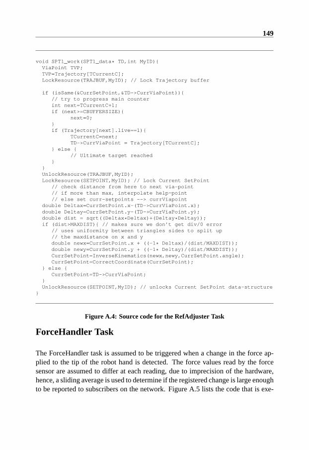
149
void SPT1_work(SPT1_data * TD,int MyID){ViaPoint TVP;TVP=Trajectory[TCurrentC];LockResource(TRAJBUF,MyID); // Lock Trajectory buffer
if (isSame(&CurrSetPoint,&TD->CurrViaPoint)){// try to progress main counterint next=TCurrentC+1;if (next>=CBUFFERSIZE){
next=0;}if (Trajectory[next].live==1){
TCurrentC=next;TD->CurrViaPoint = Trajectory[TCurrentC];
} else {// Ultimate target reached
}}UnlockResource(TRAJBUF,MyID);LockResource(SETPOINT,MyID); // Lock Current SetPoint
// check distance from here to next via-point// if more than max, interpolate help-point// else set curr-setpoints --> currViapoint
double Deltax=CurrSetPoint.x-(TD->CurrViaPoint.x);double Deltay=CurrSetPoint.y-(TD->CurrViaPoint.y);double dist = sqrt((Deltax * Deltax)+(Deltay * Deltay));if (dist>MAXDIST){ // makes sure we don’t get div/0 error
// uses uniformity between triangles sides to split up// the maxdistance on x and ydouble newx=CurrSetPoint.x + ((-1 * Deltax)/(dist/MAXDIST));double newy=CurrSetPoint.y + ((-1 * Deltay)/(dist/MAXDIST));CurrSetPoint=InverseKinematics(newx,newy,CurrSetPoint.angle);CurrSetPoint=CorrectCoordinate(CurrSetPoint);
} else {CurrSetPoint=TD->CurrViaPoint;
}UnlockResource(SETPOINT,MyID); // unlocks Current SetPoint data-structure
}
Figure A.4: Source code for the RefAdjuster Task
ForceHandler Task
The ForceHandler task is assumed to be triggered when a change in the force ap-plied to the tip of the robot hand is detected. The force values read by the forcesensor are assumed to differ at each reading, due to imprecision of the hardware,hence, a sliding average is used to determine if the registered change is large enoughto be reported to subscribers on the network. Figure A.5 lists the code that is exe-
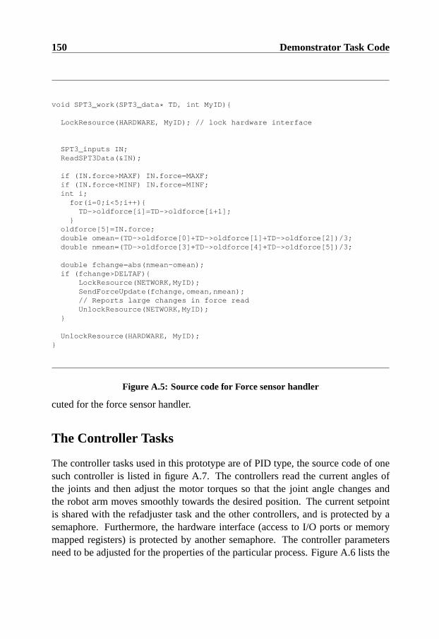
150 Demonstrator Task Code
void SPT3_work(SPT3_data * TD, int MyID){
LockResource(HARDWARE, MyID); // lock hardware interface
SPT3_inputs IN;ReadSPT3Data(&IN);
if (IN.force>MAXF) IN.force=MAXF;if (IN.force<MINF) IN.force=MINF;int i;
for(i=0;i<5;i++){TD->oldforce[i]=TD->oldforce[i+1];
}oldforce[5]=IN.force;double omean=(TD->oldforce[0]+TD->oldforce[1]+TD->oldforce[2])/3;double nmean=(TD->oldforce[3]+TD->oldforce[4]+TD->oldforce[5])/3;
double fchange=abs(nmean-omean);if (fchange>DELTAF){
LockResource(NETWORK,MyID);SendForceUpdate(fchange,omean,nmean);// Reports large changes in force readUnlockResource(NETWORK,MyID);
}
UnlockResource(HARDWARE, MyID);}
Figure A.5: Source code for Force sensor handler
cuted for the force sensor handler.
The Controller Tasks
The controller tasks used in this prototype are of PID type, the source code of onesuch controller is listed in figure A.7. The controllers read the current angles ofthe joints and then adjust the motor torques so that the joint angle changes andthe robot arm moves smoothly towards the desired position. The current setpointis shared with the refadjuster task and the other controllers, and is protected by asemaphore. Furthermore, the hardware interface (access to I/O ports or memorymapped registers) is protected by another semaphore. The controller parametersneed to be adjusted for the properties of the particular process. Figure A.6 lists the

151
void PT2_init(PT2_data * TD,int MyID){// Example controller parameters
const double K = 50; // Decide P partconst double Ti = 0.25; // Decide I partconst double Td = 0.2; // Decide D Partconst double h = 0.1; // Controllers assumed sampling periodconst double N = 10; // Maximum derivative Gain
const double Tr = 1; // Tracking constant - for anti-windupconst double beta = 1; // Setpoint weighting
// Pre-calculated coefficientsTD->K = K;TD->bi = K * h/Ti;TD->ad = Td/(Td + N * h);TD->bd = K * Td* N/(Td + N * h);TD->tk = h/Tr;TD->beta = beta;
// State variablesTD->yold = Get_init_pos(3);TD->ui = 0;TD->ud = 0;
}
Figure A.6: A. Initialization of constants
initialization part of the controllers where controller parameters are set and constantexpressions are precalculated.
Watchdog task
The watchdog task runs periodically to check the integrity of the control system.This is done by examining a set of time-stamps indicating when the controller taskslast read data from the hardware interface. If the controllers have omitted readingthe sensor values within a certain time the watch-dog task performs a dummy read-operation to avoid an incorrect state of the hardware. In addition, the periodiccontroller tasks update individual time-stamps so that the watch-dog task can detectthey are alive and operating. The watch-dog task also sends status messages toa monitoring node on the network so that cooperating nodes can detect systemfailures. Figure A.8 contains source code for this task.
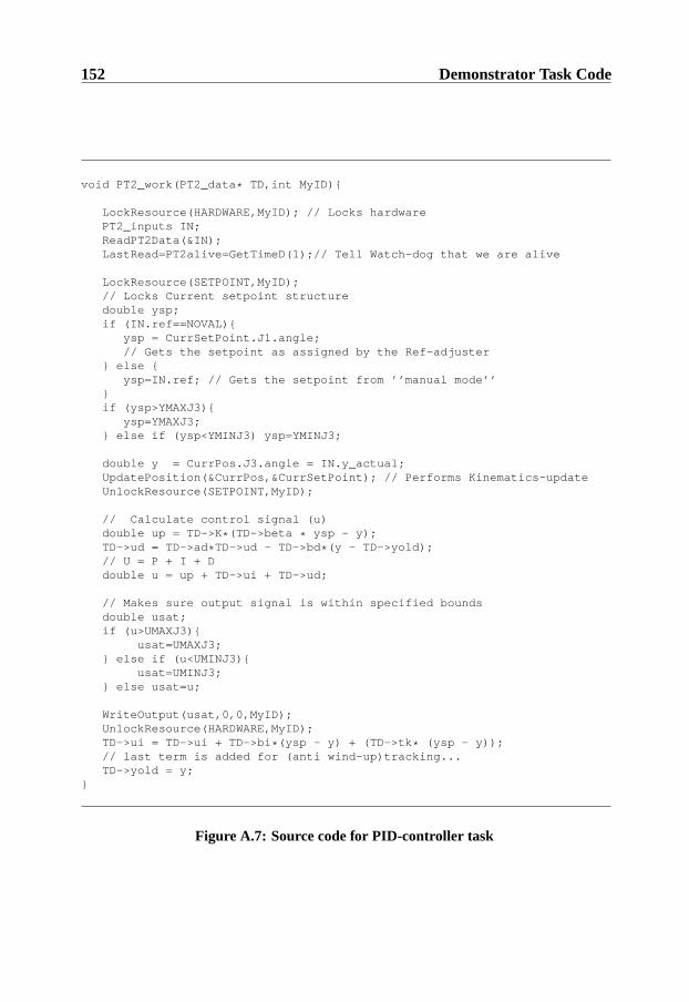
152 Demonstrator Task Code
void PT2_work(PT2_data * TD,int MyID){
LockResource(HARDWARE,MyID); // Locks hardwarePT2_inputs IN;ReadPT2Data(&IN);LastRead=PT2alive=GetTimeD(1);// Tell Watch-dog that we are alive
LockResource(SETPOINT,MyID);// Locks Current setpoint structuredouble ysp;if (IN.ref==NOVAL){
ysp = CurrSetPoint.J1.angle;// Gets the setpoint as assigned by the Ref-adjuster
} else {ysp=IN.ref; // Gets the setpoint from ’’manual mode’’
}if (ysp>YMAXJ3){
ysp=YMAXJ3;} else if (ysp<YMINJ3) ysp=YMINJ3;
double y = CurrPos.J3.angle = IN.y_actual;UpdatePosition(&CurrPos,&CurrSetPoint); // Performs Kinematics-updateUnlockResource(SETPOINT,MyID);
// Calculate control signal (u)double up = TD->K * (TD->beta * ysp - y);TD->ud = TD->ad * TD->ud - TD->bd * (y - TD->yold);// U = P + I + Ddouble u = up + TD->ui + TD->ud;
// Makes sure output signal is within specified boundsdouble usat;if (u>UMAXJ3){
usat=UMAXJ3;} else if (u<UMINJ3){
usat=UMINJ3;} else usat=u;
WriteOutput(usat,0,0,MyID);UnlockResource(HARDWARE,MyID);TD->ui = TD->ui + TD->bi * (ysp - y) + (TD->tk * (ysp - y));// last term is added for (anti wind-up)tracking...TD->yold = y;
}
Figure A.7: Source code for PID-controller task

153
void PT3_work(PT3_data * TD,int MyID){
LockResource(HARDWARE,MyID); //Locks hardware interfacedouble Now = GetTimeD(1);double SinceR=(Now-LastRead);double SincePT0=(Now-PT0alive);double SincePT1=(Now-PT1alive);double SincePT2=(Now-PT2alive);int status=0;if ((LastRead!=0.0) && (SinceR>MAXPOLLTIME)){
DummyReadHWinterface();LastRead=GetTime(1);
}UnlockResouce(HARDWARE,MyID);
if ((PT0alive!=0.0)&&(SincePT0>(2 * PT0_PERIOD))){// Perform some local error-handlingstatus+=ErrorHandling();
}if ((PT1alive!=0.0)&&(SincePT1>(2 * PT1_PERIOD))){
// Perform some local error-handlingstatus+=ErrorHandling();
}if ((PT2alive!=0.0)&&(SincePT2>(2 * PT2_PERIOD))){
// Perform some local error-handlingstatus+=ErrorHandling();
}LockResource(NETWORK,MyID);
// Send i’m alive messageSendIMAlive(status);UnlockResource(NETWORK,MyID);
}
Figure A.8: Source code for Watchdog Task

154 Demonstrator Task Code

Appendix B
Demonstrator Tasks Testing
This appendix contains the detailed description of how equivalence partitioningwas done on each task to derive classes of input data. As previously mentioned,there are several methods for deriving this kind of input data. The method usedfor this experiment is a refinement of equivalence partitioning and pair-wise com-bination coverage (for example, compare with Ammann and Offutt (Ammann &Offutt 1994)), adapted for temporal unit testing.
TrajectoryMgr testing
The behavior of this task when invoked is dependent on the inputs read from thenetwork and the state of the circular trajectory buffer at the beginning of the test.Three properties of these input data were suspected of influencing the temporalbehavior of this task. The parameters and their associated classes of inputs are listedin table B.1. One of these parameters is the size of the coordinate buffer when anew coordinate is received. This parameter is denoted “Size of Buffer” in the table.Another parameter is the actual type of operation sent to the trajectory manager.This parameter is called “Operation” in the table and we distinguish between anadjust command for a coordinate at position 10 in the buffer and coordinate 99 inthe buffer. The last parameter is termed “Coordinate” and refers to the structure ofthe actual coordinate that should be added to the trajectory. The variables N1 andN2 used in table B.1 are random positive real values between 200 and 1000. Thevalues with dagger symbols denote values outside the assumed operational profile.
155

156 Demonstrator Tasks Testing
Size of buffer Operation Coordinate0 Insert (N1,N2,1.57)15 Move All (-N1,N2,0.0)99 Adjust (10) (N1, -N2, 3.15)†100 Adjust (99) (0,0,0.0)†
Table B.1: Equivalence partitioning of TrajectoryMgr
Test case Size of buffer Operation Coordinate1 0 Insert (N,N,1.57)2 0 Move All (N, -N, 3.15)3 0 Adjust(10) (0,0,0.0)4 0 Adjust (99) (-N,N,0.0)5 15 Insert (0,0,0.0)6 15 Move All (-N,N,0.0)7 15 Adjust(10) (N,N,1.57)8 15 Adjust(99) (N, -N, 3.15)9 99 Insert (N, -N, 3.15)10 99 Move All (N,N,1.57)11 99 Adjust(10) (-N,N,0.0)12 99 Adjust(99) (0,0,0.0)13 100 Insert (-N,N,0.0)14 100 Move All (0,0,0.0)15 100 Adjust(10) (N, -N, 3.15)16 100 Adjust(99) (N,N,1.57)
Table B.2: Pair-wise combination of test parameters

157
Test Case Execution pattern1 10,8 +T 4,9 -T 4,4 +S 13,7 -S 3,42 6,6 +T 4,6 -T 3 +S 50,1 -S 3,63 6,7 +T 4,7 -T 3,2 +S 1,9 -S 3,44 6,5 +T 4,7 -T 3,6 +S 1,9 -S 3,35 5,5 +T 4,3 -T 3 +S 11,8 -S 3,26 5,7 +T 4,7 -T 3 +S 10,3 -S 3,17 5,6 +T 4,4 -T 3 +S 5,1 -S 38 5,4 +T 4,2 -T 3 +S 1,9 -S 39 5,6 +T 4,2 -T 2,9 +S 9 -S 310 10,5 +T 5,5 -T 4,5 +S 399,9 -S 3,511 5,3 +T 4,3 -T 2,9 +S 5,1 -S 312 5,7 +T 5,3 -T 2,8 +S 1,9 -S 3,213 5,3 +T 4,3 -T 3,1 +S 9,1 -S 3,114 5,9 +T 4,3 -T 2,9 +S 346,7 -S 3,215 5,2 +T 4,4 -T 3 +S 5,2 -S 316 5,5 +T 4,3 -T 2,9 +S 1,9 -S 3
Table B.3: Max execution times measured for TrajectoryMgr
Each value for a parameter in table B.1 should be pair-wise combined with eachvalue of the other parameters. Table B.2 lists an example test suite that providespair-wise coverage of these parameter values. Table B.3 table list the worst caseexecution times recorded for each segment when executing the task with input datasatisfying the test case descriptions in table B.2. In the execution pattern table, +Xmeans that the task locks resource X, -X means that the task unlocks resource X.
Refadjuster testing
The behavior of this task depends on the contents of the trajectory buffer. Theparameters in table B.4 have been identified to influence the execution pattern ofthis task. Here, Q1 and Q2 denote any coordinate in the first and second quadrant ofthe operational plane. The constant MAXD is the parameter deciding the maximumallowed distance between two Viapoints in the trajectory.
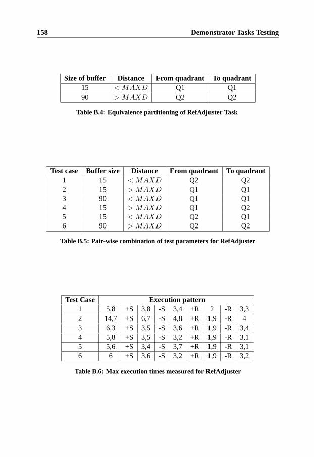
158 Demonstrator Tasks Testing
Size of buffer Distance From quadrant To quadrant15 < MAXD Q1 Q190 > MAXD Q2 Q2
Table B.4: Equivalence partitioning of RefAdjuster Task
Test case Buffer size Distance From quadrant To quadrant1 15 < MAXD Q2 Q22 15 > MAXD Q1 Q13 90 < MAXD Q1 Q14 15 > MAXD Q1 Q25 15 < MAXD Q2 Q16 90 > MAXD Q2 Q2
Table B.5: Pair-wise combination of test parameters for RefAdjuster
Test Case Execution pattern1 5,8 +S 3,8 -S 3,4 +R 2 -R 3,32 14,7 +S 6,7 -S 4,8 +R 1,9 -R 43 6,3 +S 3,5 -S 3,6 +R 1,9 -R 3,44 5,8 +S 3,5 -S 3,2 +R 1,9 -R 3,15 5,6 +S 3,4 -S 3,7 +R 1,9 -R 3,16 6 +S 3,6 -S 3,2 +R 1,9 -R 3,2
Table B.6: Max execution times measured for RefAdjuster

159
Burst of 6 sensor reads Latest sensor read1 change> DELTAF inside valid range
3 cons. changes> DELTAF outside valid rangeno changes> DELTAF
Table B.7: Equivalence partitioning of ForceHandler Task
Burst of 6 sensor reads Latest sensor readno changes> DELTAF inside valid range1 change> DELTAF inside valid range
3 cons. changes> DELTAF inside valid rangeno changes> DELTAF outside valid range1 change> DELTAF outside valid range
3 cons. changes> DELTAF outside valid range
Table B.8: Pairwise test-data used for ForceHandler Task
ForceHandler testing
This task locks different resources depending on the relation between input values.This needs some special consideration during testing of timeliness, since the worstcase behavior for each of the possible task execution patterns needs to be measured.From a unit testing perspective, the behavior of this task depends on the last sensorvalues read. Also, the sizes of the sensor values read may affect the executionpattern of the task. Table B.7 contains the equivalence partitioning used for testingthis task. Table B.8 lists the test data that fulfill pair-wise coverage of these classes.
Since the execution patterns for this task are different depending on the inputdata, two different worst-case execution behavior tables can be extracted. Theseare listed in tables B.9 and B.10.
Controller tasks testing
The controller tasks have relatively simple control flows, but the robot arm be-havior depend on the correctness and timeliness of the calculations performed bythese tasks. The behavior of a controller task depends on the active setpoints andthe current angle of the robot arm joints. The behavior also depends on the statevariables calculated by the controller in the previous activation step. Since theFlexcon application can be executed in closed loop with a simulated robot arm in
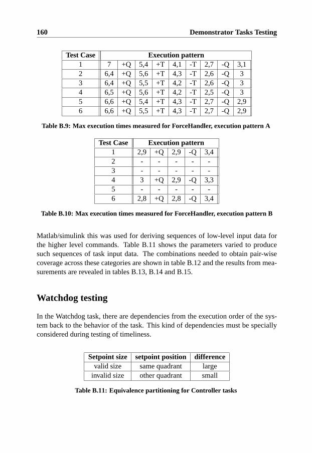
160 Demonstrator Tasks Testing
Test Case Execution pattern1 7 +Q 5,4 +T 4,1 -T 2,7 -Q 3,12 6,4 +Q 5,6 +T 4,3 -T 2,6 -Q 33 6,4 +Q 5,5 +T 4,2 -T 2,6 -Q 34 6,5 +Q 5,6 +T 4,2 -T 2,5 -Q 35 6,6 +Q 5,4 +T 4,3 -T 2,7 -Q 2,96 6,6 +Q 5,5 +T 4,3 -T 2,7 -Q 2,9
Table B.9: Max execution times measured for ForceHandler, execution pattern A
Test Case Execution pattern1 2,9 +Q 2,9 -Q 3,42 - - - - -3 - - - - -4 3 +Q 2,9 -Q 3,35 - - - - -6 2,8 +Q 2,8 -Q 3,4
Table B.10: Max execution times measured for ForceHandler, execution pattern B
Matlab/simulink this was used for deriving sequences of low-level input data forthe higher level commands. Table B.11 shows the parameters varied to producesuch sequences of task input data. The combinations needed to obtain pair-wisecoverage across these categories are shown in table B.12 and the results from mea-surements are revealed in tables B.13, B.14 and B.15.
Watchdog testing
In the Watchdog task, there are dependencies from the execution order of the sys-tem back to the behavior of the task. This kind of dependencies must be speciallyconsidered during testing of timeliness.
Setpoint size setpoint position differencevalid size same quadrant large
invalid size other quadrant small
Table B.11: Equivalence partitioning for Controller tasks

161
Setpoint size setpoint position differencevalid size same quadrant large
invalid size same quadrant smallinvalid size other quadrant largevalid size other quadrant small
Table B.12: Pairwise test-data used for controller tasks
Test Case Execution pattern1 11,5 +Q 8 +R 12,3 -R 6,7 -Q 3,52 8,5 +Q 6,2 +R 10,2 -R 6,4 -Q 33 8,5 +Q 5,7 +R 10,6 -R 6,6 -Q 3,24 8,6 +Q 5,5 +R 10,5 -R 6,3 -Q 3
Table B.13: Max execution times measured for Controller 1
Test Case Execution pattern1 12,2 +Q 12,4 +R 13,1 -R 14,6 -Q 11,92 11,4 +Q 12,4 +R 13,9 -R 13,8 -Q 3,13 11,2 +Q 12,6 +R 14,4 -R 13,7 -Q 34 11,5 +Q 6,5 +R 13,8 -R 13 -Q 3
Table B.14: Max execution times measured for Controller 2
Test Case Execution pattern1 9,5 +Q 7,8 +R 10,6 -R 7,6 -Q 3,32 6,8 +Q 5,3 +R 8,1 -R 5,2 -Q 2,93 9,6 +Q 7,7 +R 10,2 -R 7,7 -Q 3,44 7,1 +Q 5,7 +R 7,9 -R 5,8 -Q 3
Table B.15: Max execution times measured for Controller 3
Task Execution patternWatchDog 7,5 +Q 4,5 -Q 3,9 +T 4,1 -T 3,1
Table B.16: Max execution times measured for Watchdog

162 Demonstrator Tasks Testing
In particular, the task’s execution behavior (control flow) depends on the rela-tion between a set of shared time stamps and the current time. That means that theexecution time depend on the actual order and timing of other tasks. These vari-ables cannot be controlled when all tasks are run concurrently without introducingprobe effects. Optimally, this kind of relation between execution order and exe-cution time should be included in the model used for test case generation. In themutation-based testing framework, this addition can be implemented by a special-ized execution segment as described in section 10.1.2. Since the impact is smalland the dependencies are limited to a single task for this application, we do notmodel these dependencies in this case study.
For the measurements, the shared time stamps were set so that the program pathwith the intuitively longest execution time would occur when the task was run insingularity (see table B.16).
Appendix C
Case-Study Test ExecutionResults
This appendix contains figures that visualize the results from the experiment de-scribed in section 9.4.2. In particular, figure C.1 shows the average number of testcases that resulted in timeliness failures when five different test suites fulfillingthe (∆ = 20) execution time testing criteria were run on 7 software variants withseeded timeliness errors. Each test suite contained 7 test cases, therefore this is themaximum number of effective test cases (max of the z-axis). In figure C.2 and fig-ure C.3 the most and least effective test suite for each software variant are plottedin the same way.
For comparison, five test suites with 10 randomly generated test cases were runon each of the seven software variants. In the same way, the average number ofeffective test cases are plotted in figure C.4. The result from the most effectiverandom test suites for each version is plotted in figure C.6 and the least effectiverandom test suites are plotted in figure C.5.
163

164 Case-Study Test Execution Results
12
34
56
7 50150
250350
450
0
2
4
6
8
10
LatenessSoftware Version
Effe
ctiv
e T
est C
ases
Figure C.1: Average number of failures detected in seeded variants using mutationtesting
12
34
56
7 50150
250350
450
0
2
4
6
8
10
LatenessSoftware Version
Effe
ctiv
e T
est C
ases
Figure C.2: Least number of failures detected in seeded variants using mutationtesting

165
12
34
56
7 50150
250350
450
0
2
4
6
8
10
LatenessSoftware Version
Effe
ctiv
e T
est C
ases
Figure C.3: Most number of failures detected in seeded variants using mutationtesting
12
34
56
7 50150
250350
450
0
2
4
6
8
10
LatenessSoftware Version
Effe
ctiv
e T
est C
ases
Figure C.4: Average number of failures detected in seeded variants using randomtesting

166 Case-Study Test Execution Results
12
34
56
7 50150
250350
450
0
2
4
6
8
10
LatenessSoftware Version
Effe
ctiv
e T
est C
ases
Figure C.5: Least number of failures detected in seeded variants using randomtesting
12
34
56
7 50150
250350
450
0
2
4
6
8
10
LatenessSoftware Version
Effe
ctiv
e T
est C
ases
Figure C.6: Most number of failures detected in seeded variants using randomtesting

Appendix D
Mutation Operators Overview
This appendix contains a classification (see figure D.1) of the mutation operatorsdefined in chapter 6 as well as an overview of how related mutation operators canbe implemented using the guidelines in section 10.1.2.
167
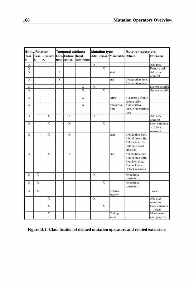
168 Mutation Operators Overview
Entity/Relation Mutation operators
Task
xi
Task
xj
Resource
rm
Exec.
time
Critical
section
Input
constraints
Add Remove Manipulate Defined Extension
X X Add task
X X Remove task
X X start Add exec.
segment
X X end +execution time,
+execution timeX X X System specific
X X X System specific
X X Offset +pattern offset, -
pattern offsetX X Interarrival-
time
+interarrival-
time, -interarrival-
time
X X X X Add exec.
segment
X X X X Lock omission
+ Unlock
omission
X X X start +hold time shift,
-hold time shift,
+lock time, -
lock time, Lock
omission
X X X end +hold time shift,
-hold time shift,
+unlock time,
-unlock time,
Unlock omission
X X X Precedence
constraint +
X X X Precedence
constraint -
X X Relative
priority
Trivial
X X Add exec.
segments
X X Lock omission
+ Unlock
X Ceiling
value
Mutate exec.
env. property
Temporal attribute Mutation type
Figure D.1: Classification of defined mutation operators and related extensions
Department of Computer and Information ScienceLinköpings universitet
Dissertations
Linköping Studies in Science and Technology
No 14 Anders Haraldsson: A Program ManipulationSystem Based on Partial Evaluation, 1977, ISBN91-7372-144-1.
No 17 Bengt Magnhagen: Probability Based Verificationof Time Margins in Digital Designs, 1977, ISBN91-7372-157-3.
No 18 Mats Cedwall: Semantisk analys av process-beskrivningar i naturligt språk, 1977, ISBN 91-7372-168-9.
No 22 Jaak Urmi: A Machine Independent LISP Compil-er and its Implications for Ideal Hardware, 1978,ISBN 91-7372-188-3.
No 33 Tore Risch: Compilation of Multiple File Queriesin a Meta-Database System 1978, ISBN 91-7372-232-4.
No 51 Erland Jungert: Synthesizing Database Structuresfrom a User Oriented Data Model, 1980, ISBN 91-7372-387-8.
No 54 Sture Hägglund: Contributions to the Develop-ment of Methods and Tools for Interactive Designof Applications Software, 1980, ISBN 91-7372-404-1.
No 55 Pär Emanuelson: Performance Enhancement in aWell-Structured Pattern Matcher through PartialEvaluation, 1980, ISBN 91-7372-403-3.
No 58 Bengt Johnsson, Bertil Andersson: The Human-Computer Interface in Commercial Systems, 1981,ISBN 91-7372-414-9.
No 69 H. Jan Komorowski: A Specification of an Ab-stract Prolog Machine and its Application to PartialEvaluation, 1981, ISBN 91-7372-479-3.
No 71 René Reboh: Knowledge Engineering Techniquesand Tools for Expert Systems, 1981, ISBN 91-7372-489-0.
No 77 Östen Oskarsson: Mechanisms of Modifiability inlarge Software Systems, 1982, ISBN 91-7372-527-7.
No 94 Hans Lunell: Code Generator Writing Systems,1983, ISBN 91-7372-652-4.
No 97 Andrzej Lingas: Advances in Minimum WeightTriangulation, 1983, ISBN 91-7372-660-5.
No 109 Peter Fritzson: Towards a Distributed Program-ming Environment based on Incremental Compila-tion,1984, ISBN 91-7372-801-2.
No 111 Erik Tengvald: The Design of Expert PlanningSystems. An Experimental Operations PlanningSystem for Turning, 1984, ISBN 91-7372-805-5.
No 155 Christos Levcopoulos: Heuristics for MinimumDecompositions of Polygons, 1987, ISBN 91-7870-133-3.
No 165 James W. Goodwin: A Theory and System for
Non-Monotonic Reasoning, 1987, ISBN 91-7870-183-X.
No 170 Zebo Peng: A Formal Methodology for AutomatedSynthesis of VLSI Systems, 1987, ISBN 91-7870-225-9.
No 174 Johan Fagerström: A Paradigm and System forDesign of Distributed Systems, 1988, ISBN 91-7870-301-8.
No 192 Dimiter Driankov: Towards a Many Valued Logicof Quantified Belief, 1988, ISBN 91-7870-374-3.
No 213 Lin Padgham: Non-Monotonic Inheritance for anObject Oriented Knowledge Base, 1989, ISBN 91-7870-485-5.
No 214 Tony Larsson: A Formal Hardware Description andVerification Method, 1989, ISBN 91-7870-517-7.
No 221 Michael Reinfrank: Fundamentals and LogicalFoundations of Truth Maintenance, 1989, ISBN 91-7870-546-0.
No 239 Jonas Löwgren: Knowledge-Based Design Supportand Discourse Management in User Interface Man-agement Systems, 1991, ISBN 91-7870-720-X.
No 244 Henrik Eriksson: Meta-Tool Support for Knowl-edge Acquisition, 1991, ISBN 91-7870-746-3.
No 252 Peter Eklund: An Epistemic Approach to Interac-tive Design in Multiple Inheritance Hierar-chies,1991, ISBN 91-7870-784-6.
No 258 Patrick Doherty: NML3 - A Non-Monotonic For-malism with Explicit Defaults, 1991, ISBN 91-7870-816-8.
No 260 Nahid Shahmehri: Generalized Algorithmic De-bugging, 1991, ISBN 91-7870-828-1.
No 264 Nils Dahlbäck: Representation of Discourse-Cog-nitive and Computational Aspects, 1992, ISBN 91-7870-850-8.
No 265 Ulf Nilsson: Abstract Interpretations and AbstractMachines: Contributions to a Methodology for theImplementation of Logic Programs, 1992, ISBN 91-7870-858-3.
No 270 Ralph Rönnquist: Theory and Practice of Tense-bound Object References, 1992, ISBN 91-7870-873-7.
No 273 Björn Fjellborg: Pipeline Extraction for VLSI DataPath Synthesis, 1992, ISBN 91-7870-880-X.
No 276 Staffan Bonnier: A Formal Basis for Horn ClauseLogic with External Polymorphic Functions, 1992,ISBN 91-7870-896-6.
No 277 Kristian Sandahl: Developing Knowledge Man-agement Systems with an Active Expert Methodolo-gy, 1992, ISBN 91-7870-897-4.
No 281 Christer Bäckström: Computational Complexity

of Reasoning about Plans, 1992, ISBN 91-7870-979-2.
No 292 Mats Wirén: Studies in Incremental Natural Lan-guage Analysis, 1992, ISBN 91-7871-027-8.
No 297 Mariam Kamkar: Interprocedural Dynamic Slic-ing with Applications to Debugging and Testing,1993, ISBN 91-7871-065-0.
No 302 Tingting Zhang: A Study in Diagnosis Using Clas-sification and Defaults, 1993, ISBN 91-7871-078-2.
No 312 Arne Jönsson: Dialogue Management for NaturalLanguage Interfaces - An Empirical Approach,1993, ISBN 91-7871-110-X.
No 338 Simin Nadjm-Tehrani: Reactive Systems in Phys-ical Environments: Compositional Modelling andFramework for Verification, 1994, ISBN 91-7871-237-8.
No 371 Bengt Savén: Business Models for Decision Sup-port and Learning. A Study of Discrete-Event Man-ufacturing Simulation at Asea/ABB 1968-1993,1995, ISBN 91-7871-494-X.
No 375 Ulf Söderman: Conceptual Modelling of ModeSwitching Physical Systems, 1995, ISBN 91-7871-516-4.
No 383 Andreas Kågedal: Exploiting Groundness in Log-ic Programs, 1995, ISBN 91-7871-538-5.
No 396 George Fodor: Ontological Control, Description,Identification and Recovery from Problematic Con-trol Situations, 1995, ISBN 91-7871-603-9.
No 413 Mikael Pettersson: Compiling Natural Semantics,1995, ISBN 91-7871-641-1.
No 414 Xinli Gu: RT Level Testability Improvement byTestability Analysis and Transformations, 1996,ISBN 91-7871-654-3.
No 416 Hua Shu: Distributed Default Reasoning, 1996,ISBN 91-7871-665-9.
No 429 Jaime Villegas: Simulation Supported IndustrialTraining from an Organisational Learning Perspec-tive - Development and Evaluation of the SSITMethod, 1996, ISBN 91-7871-700-0.
No 431 Peter Jonsson: Studies in Action Planning: Algo-rithms and Complexity, 1996, ISBN 91-7871-704-3.
No 437 Johan Boye: Directional Types in Logic Program-ming, 1996, ISBN 91-7871-725-6.
No 439 Cecilia Sjöberg: Activities, Voices and Arenas:Participatory Design in Practice, 1996, ISBN 91-7871-728-0.
No 448 Patrick Lambrix: Part-Whole Reasoning in De-scription Logics, 1996, ISBN 91-7871-820-1.
No 452 Kjell Orsborn: On Extensible and Object-Rela-tional Database Technology for Finite ElementAnalysis Applications, 1996, ISBN 91-7871-827-9.
No 459 Olof Johansson: Development Environments forComplex Product Models, 1996, ISBN 91-7871-855-4.
No 461 Lena Strömbäck: User-Defined Constructions in
Unification-Based Formalisms,1997, ISBN 91-7871-857-0.
No 462 Lars Degerstedt: Tabulation-based Logic Program-ming: A Multi-Level View of Query Answering,1996, ISBN 91-7871-858-9.
No 475 Fredrik Nilsson: Strategi och ekonomisk styrning -En studie av hur ekonomiska styrsystem utformasoch används efter företagsförvärv, 1997, ISBN 91-7871-914-3.
No 480 Mikael Lindvall: An Empirical Study of Require-ments-Driven Impact Analysis in Object-OrientedSoftware Evolution, 1997, ISBN 91-7871-927-5.
No 485 Göran Forslund: Opinion-Based Systems: The Co-operative Perspective on Knowledge-Based Deci-sion Support, 1997, ISBN 91-7871-938-0.
No 494 Martin Sköld: Active Database Management Sys-tems for Monitoring and Control, 1997, ISBN 91-7219-002-7.
No 495 Hans Olsén: Automatic Verification of Petri Nets ina CLP framework, 1997, ISBN 91-7219-011-6.
No 498 Thomas Drakengren: Algorithms and Complexityfor Temporal and Spatial Formalisms, 1997, ISBN91-7219-019-1.
No 502 Jakob Axelsson: Analysis and Synthesis of Hetero-geneous Real-Time Systems, 1997, ISBN 91-7219-035-3.
No 503 Johan Ringström: Compiler Generation for Data-Parallel Programming Langugaes from Two-LevelSemantics Specifications, 1997, ISBN 91-7219-045-0.
No 512 Anna Moberg: Närhet och distans - Studier avkommunikationsmmönster i satellitkontor och flexi-bla kontor, 1997, ISBN 91-7219-119-8.
No 520 Mikael Ronström: Design and Modelling of a Par-allel Data Server for Telecom Applications, 1998,ISBN 91-7219-169-4.
No 522 Niclas Ohlsson: Towards Effective Fault Prevention - An Empirical Study in Software Engi-neering, 1998, ISBN 91-7219-176-7.
No 526 Joachim Karlsson: A Systematic Approach for Pri-oritizing Software Requirements, 1998, ISBN 91-7219-184-8.
No 530 Henrik Nilsson: Declarative Debugging for LazyFunctional Languages, 1998, ISBN 91-7219-197-x.
No 555 Jonas Hallberg: Timing Issues in High-Level Syn-thesis,1998, ISBN 91-7219-369-7.
No 561 Ling Lin: Management of 1-D Sequence Data -From Discrete to Continuous, 1999, ISBN 91-7219-402-2.
No 563 Eva L Ragnemalm: Student Modelling based onCollaborative Dialogue with a Learning Compan-ion, 1999, ISBN 91-7219-412-X.
No 567 Jörgen Lindström: Does Distance matter? On geo-graphical dispersion in organisations, 1999, ISBN91-7219-439-1.
No 582 Vanja Josifovski: Design, Implementation and
Evaluation of a Distributed Mediator System forData Integration, 1999, ISBN 91-7219-482-0.
No 589 Rita Kovordányi: Modeling and Simulating Inhib-itory Mechanisms in Mental Image Reinterpretation- Towards Cooperative Human-Computer Creativi-ty, 1999, ISBN 91-7219-506-1.
No 592 Mikael Ericsson: Supporting the Use of DesignKnowledge - An Assessment of CommentingAgents, 1999, ISBN 91-7219-532-0.
No 593 Lars Karlsson: Actions, Interactions and Narra-tives, 1999, ISBN 91-7219-534-7.
No 594 C. G. Mikael Johansson: Social and Organization-al Aspects of Requirements Engineering Methods -A practice-oriented approach, 1999, ISBN 91-7219-541-X.
No 595 Jörgen Hansson: Value-Driven Multi-Class Over-load Management in Real-Time Database Systems,1999, ISBN 91-7219-542-8.
No 596 Niklas Hallberg: Incorporating User Values in theDesign of Information Systems and Services in thePublic Sector: A Methods Approach, 1999, ISBN91-7219-543-6.
No 597 Vivian Vimarlund: An Economic Perspective onthe Analysis of Impacts of Information Technology:From Case Studies in Health-Care towards GeneralModels and Theories, 1999, ISBN 91-7219-544-4.
No 598 Johan Jenvald: Methods and Tools in Computer-Supported Taskforce Training, 1999, ISBN 91-7219-547-9.
No 607 Magnus Merkel: Understanding and enhancingtranslation by parallel text processing, 1999, ISBN91-7219-614-9.
No 611 Silvia Coradeschi: Anchoring symbols to sensorydata, 1999, ISBN 91-7219-623-8.
No 613 Man Lin: Analysis and Synthesis of ReactiveSystems: A Generic Layered ArchitecturePerspective, 1999, ISBN 91-7219-630-0.
No 618 Jimmy Tjäder: Systemimplementering i praktiken- En studie av logiker i fyra projekt, 1999, ISBN 91-7219-657-2.
No 627 Vadim Engelson: Tools for Design, InteractiveSimulation, and Visualization of Object-OrientedModels in Scientific Computing, 2000, ISBN 91-7219-709-9.
No 637 Esa Falkenroth: Database Technology for Controland Simulation, 2000, ISBN 91-7219-766-8.
No 639 Per-Arne Persson: Bringing Power andKnowledge Together: Information Systems Designfor Autonomy and Control in Command Work,2000, ISBN 91-7219-796-X.
No 660 Erik Larsson: An Integrated System-Level Designfor Testability Methodology, 2000, ISBN 91-7219-890-7.
No 688 Marcus Bjäreland: Model-based ExecutionMonitoring, 2001, ISBN 91-7373-016-5.
No 689 Joakim Gustafsson: Extending Temporal ActionLogic, 2001, ISBN 91-7373-017-3.
No 720 Carl-Johan Petri: Organizational Information Pro-vision - Managing Mandatory and Discretionary Useof Information Technology, 2001, ISBN-91-7373-126-9.
No 724 Paul Scerri: Designing Agents for Systems withAdjustable Autonomy, 2001, ISBN 91 7373 207 9.
No 725 Tim Heyer: Semantic Inspection of Software Arti-facts: From Theory to Practice, 2001, ISBN 91 7373208 7.
No 726 Pär Carlshamre: A Usability Perspective on Re-quirements Engineering - From Methodology toProduct Development, 2001, ISBN 91 7373 212 5.
No 732 Juha Takkinen: From Information Management toTask Management in Electronic Mail, 2002, ISBN91 7373 258 3.
No 745 Johan Åberg: Live Help Systems: An Approach toIntelligent Help for Web Information Systems,2002, ISBN 91-7373-311-3.
No 746 Rego Granlund: Monitoring Distributed Team-work Training, 2002, ISBN 91-7373-312-1.
No 757 Henrik André-Jönsson: Indexing Strategies forTime Series Data, 2002, ISBN 917373-346-6.
No 747 Anneli Hagdahl: Development of IT-suppor-ted In-ter-organisational Collaboration - A Case Study inthe Swedish Public Sector, 2002, ISBN 91-7373-314-8.
No 749 Sofie Pilemalm: Information Technology for Non-Profit Organisations - Extended Participatory De-sign of an Information System for Trade Union ShopStewards, 2002, ISBN 91-7373-318-0.
No 765 Stefan Holmlid: Adapting users: Towards a theoryof use quality, 2002, ISBN 91-7373-397-0.
No 771 Magnus Morin: Multimedia Representations ofDistributed Tactical Operations, 2002, ISBN 91-7373-421-7.
No 772 Pawel Pietrzak: A Type-Based Framework for Lo-cating Errors in Constraint Logic Programs, 2002,ISBN 91-7373-422-5.
No 758 Erik Berglund: Library Communication AmongProgrammers Worldwide, 2002,ISBN 91-7373-349-0.
No 774 Choong-ho Yi: Modelling Object-OrientedDynamic Systems Using a Logic-Based Framework,2002, ISBN 91-7373-424-1.
No 779 Mathias Broxvall: A Study in the Computational Complexity of Temporal Reasoning, 2002, ISBN 91-7373-440-3.
No 793 Asmus Pandikow: A Generic Principle for Enabling Interoperability of Structured and Object-Oriented Analysis and Design Tools, 2002,ISBN 91-7373-479-9.
No 785 Lars Hult: Publika Informationstjänster. En studieav den Internetbaserade encyklopedins bruksegen-skaper, 2003, ISBN 91-7373-461-6.
No 800 Lars Taxén: A Framework for the Coordination ofComplex Systems´ Development, 2003, ISBN 91-7373-604-X
No 808 Klas Gäre: Tre perspektiv på förväntningar ochförändringar i samband med införande av informa-

tionsystem, 2003, ISBN 91-7373-618-X.No 821 Mikael Kindborg: Concurrent Comics - program-
ming of social agents by children, 2003,ISBN 91-7373-651-1.
No 823 Christina Ölvingson: On Development of Infor-mation Systems with GIS Functionality in PublicHealth Informatics: A Requirements EngineeringApproach, 2003, ISBN 91-7373-656-2.
No 828 Tobias Ritzau: Memory Efficient Hard Real-TimeGarbage Collection, 2003, ISBN 91-7373-666-X.
No 833 Paul Pop: Analysis and Synthesis of Communication-Intensive Heterogeneous Real-Time Systems, 2003, ISBN 91-7373-683-X.
No 852 Johan Moe: Observing the DynamicBehaviour of Large Distributed Systems to ImproveDevelopment and Testing - An Emperical Study inSoftware Engineering, 2003, ISBN 91-7373-779-8.
No 867 Erik Herzog: An Approach to Systems Engineer-ing Tool Data Representation and Exchange, 2004,ISBN 91-7373-929-4.
No 872 Aseel Berglund: Augmenting the Remote Control:Studies in Complex Information Navigation for
Digital TV, 2004, ISBN 91-7373-940-5.No 869 Jo Skåmedal: Telecommuting’s Implications on
Travel and Travel Patterns, 2004, ISBN 91-7373-935-9.
No 870 Linda Askenäs: The Roles of IT - Studies of Or-ganising when Implementing and Using EnterpriseSystems, 2004, ISBN 91-7373-936-7.
No 874 Annika Flycht-Eriksson: Design and Use of On-tologies in Information-Providing Dialogue Sys-tems, 2004, ISBN 91-7373-947-2.
No 873 Peter Bunus: Debugging Techniques for Equation-Based Languages, 2004, ISBN 91-7373-941-3.
No 876 Jonas Mellin: Resource-Predictable and EfficientMonitoring of Events, 2004, ISBN 91-7373-956-1.
No 883 Magnus Bång: Computing at the Speed of Paper:Ubiquitous Computing Environments for Health-care Professionals, 2004, ISBN 91-7373-971-5
No 882 Robert Eklund: Disfluency in Swedish human-human and human-machine travel bookingdialogues, 2004. ISBN 91-7373-966-9.
No 887 Anders Lindström: English and other Foreign Lin-quistic Elements in Spoken Swedish. Studies ofProductive Processes and their Modelling using Fi-nite-State Tools, 2004, ISBN 91-7373-981-2.
No 889 Zhiping Wang: Capacity-Constrained Production-inventory systems - Modellling and Analysis inboth a traditional and an e-business context, 2004,ISBN 91-85295-08-6.
No 893 Pernilla Qvarfordt: Eyes on Multimodal Interac-tion, 2004, ISBN 91-85295-30-2.
No 910 Magnus Kald: In the Borderland between Strategyand Management Control - Theoretical Frameworkand Empirical Evidence, 2004, ISBN 91-85295-82-5.
No 918 Jonas Lundberg: Shaping Electronic News: GenrePerspectives on Interaction Design, 2004, ISBN 91-85297-14-3.
No 900 Mattias Arvola: Shades of use: The dynamics ofinteraction design for sociable use, 2004, ISBN 91-85295-42-6.
No 920 Luis Alejandro Cortés: Verification and Schedul-ing Techniques for Real-Time Embedded Systems,2004, ISBN 91-85297-21-6.
No 929 Diana Szentivanyi: Performance Studies of Fault-Tolerant Middleware, 2005, ISBN 91-85297-58-5.
No 933 Mikael Cäker: Management Accounting as Con-structing and Opposing Customer Focus: Three CaseStudies on Management Accounting and CustomerRelations, 2005, ISBN 91-85297-64-X.
No 937 Jonas Kvarnström: TALplanner and Other Exten-sions to Temporal Action Logic, 2005, ISBN 91-85297-75-5.
No 938 Bourhane Kadmiry: Fuzzy Gain-Scheduled VisualServoing for Unmanned Helicopter, 2005, ISBN 91-85297-76-3.
No 945 Gert Jervan: Hybrid Built-In Self-Test and TestGeneration Techniques for Digital Systems, 2005,ISBN: 91-85297-97-6.
No 946 Anders Arpteg: Intelligent Semi-Structured Infor-mation Extraction, 2005, ISBN 91-85297-98-4.
No 947 Ola Angelsmark: Constructing Algorithms forConstraint Satisfaction and Related Problems -Methods and Applications, 2005, ISBN 91-85297-99-2.
No 963 Calin Curescu: Utility-based Optimisation of Re-source Allocation for Wireless Networks, 2005.ISBN 91-85457-07-8.
No 972 Björn Johansson: Joint Control in Dynamic Situa-tions, 2005, ISBN 91-85457-31-0.
No 974 Dan Lawesson: An Approach to DiagnosabilityAnalysis for Interacting Finite State Systems, 2005,ISBN 91-85457-39-6.
No 979 Claudiu Duma: Security and Trust Mechanisms forGroups in Distributed Services, 2005, ISBN 91-85457-54-X.
No 983 Sorin Manolache: Analysis and Optimisation ofReal-Time Systems with Stochastic Behaviour,2005, ISBN 91-85457-60-4.
No 986 Yuxiao Zhao: Standards-Based Application Inte-gration for Business-to-Business Communications,2005, ISBN 91-85457-66-3.
No 1004 Patrik Haslum: Admissible Heuristics for Auto-mated Planning, 2006, ISBN 91-85497-28-2.
No 1005 Aleksandra Tesanovic: Developing Re-usable and Reconfigurable Real-Time Software us-ing Aspects and Components, 2006, ISBN 91-85497-29-0.
No 1008 David Dinka: Role, Identity and Work: Extendingthe design and development agenda, 2006, ISBN 91-85497-42-8.
No 1009 Iakov Nakhimovski: Contributions to the Modelingand Simulation of Mechanical Systems with De-tailed Contact Analysis, 2006, ISBN 91-85497-43-X.
No 1013 Wilhelm Dahllöf: Exact Algorithms for Exact Sat-isfiability Problems, 2006, ISBN 91-85523-97-6.
No 1016 Levon Saldamli: PDEModelica - A High-LevelLanguage for Modeling with Partial DifferentialEquations, 2006, ISBN 91-85523-84-4.
No 1017 Daniel Karlsson: Verification of Component-basedEmbedded System Designs, 2006, ISBN 91-85523-79-8.

No 1018 Ioan Chisalita: Communication and NetworkingTechniques for Traffic Safety Systems, 2006, ISBN91-85523-77-1.
No 1019 Tarja Susi: The Puzzle of Social Activity - TheSignificance of Tools in Cognition and Coopera-tion, 2006, ISBN 91-85523-71-2.
No 1021 Andrzej Bednarski: Integrated Optimal CodeGeneration for Digital Signal Processors, 2006,ISBN 91-85523-69-0.
No 1022 Peter Aronsson: Automatic Parallelization ofEquation-Based Simulation Programs, 2006, ISBN91-85523-68-2.
No 1023 Sonia Sangari: Some Visual Correlates to FocalAccent in Swedish, 2006, ISBN 91-85523-67-4.
No 1030 Robert Nilsson: A Mutation-based Framework forAutomated Testing of Timeliness, 2006, ISBN 91-85523-35-6.
Linköping Studies in Information Science
No 1 Karin Axelsson: Metodisk systemstrukturering- attskapa samstämmighet mellan informa-tionssyste-markitektur och verksamhet, 1998. ISBN-9172-19-296-8.
No 2 Stefan Cronholm: Metodverktyg och användbar-het - en studie av datorstödd metodbaserad syste-mutveckling, 1998. ISBN-9172-19-299-2.
No 3 Anders Avdic: Användare och utvecklare - om an-veckling med kalkylprogram, 1999. ISBN-91-7219-606-8.
No 4 Owen Eriksson: Kommunikationskvalitet hos in-formationssystem och affärsprocesser, 2000. ISBN91-7219-811-7.
No 5 Mikael Lind: Från system till process - kriterier förprocessbestämning vid verksamhetsanalys, 2001,ISBN 91-7373-067-X
No 6 Ulf Melin: Koordination och informationssystem iföretag och nätverk, 2002, ISBN 91-7373-278-8.
No 7 Pär J. Ågerfalk: Information Systems Actability -Understanding Information Technology as a Toolfor Business Action and Communication, 2003,ISBN 91-7373-628-7.
No 8 Ulf Seigerroth: Att förstå och förändrasystemutvecklingsverksamheter - en taxonomiför metautveckling, 2003, ISBN91-7373-736-4.
No 9 Karin Hedström: Spår av datoriseringens värden -Effekter av IT i äldreomsorg, 2004, ISBN 91-7373-963-4.
No 10 Ewa Braf: Knowledge Demanded for Action -Studies on Knowledge Mediation in Organisations,2004, ISBN 91-85295-47-7.
No 11 Fredrik Karlsson: Method Configuration -method and computerized tool support, 2005, ISBN91-85297-48-8.
No 12 Malin Nordström: Styrbar systemförvaltning - Attorganisera systemförvaltningsverksamhet medhjälp av effektiva förvaltningsobjekt, 2005, ISBN91-85297-60-7.
No 13 Stefan Holgersson: Yrke: POLIS - Yrkeskunskap,motivation, IT-system och andra förutsättningar för
polisarbete, 2005, ISBN 91-85299-43-X.