a multi-scale approach to shaping carbon …thesis.library.caltech.edu/8436/1/lyon- thesis...
TRANSCRIPT

A Multi-Scale Approach to Shaping
Carbon Nanotube Structures for
Hollow Microneedles
Thesis by
Bradley Lyon
In Partial Fulfillment of the Requirements
for the Degree of
Doctor of Philosophy
CALIFORNIA INSTITUTE OF TECHNOLOGY
Pasadena, California
2014
(Defended May 13, 2014)

ii
2014
Bradley Lyon
All Rights Reserved

iii
Acknowledgements
I would like to begin by thanking my advisor, Professor Morteza Gharib, for his inspiring
guidance and leadership throughout this project. I would also like to thank my thesis committee,
Professors Beverley McKeon, Guruswami Ravichandran, and Yu-Chong Tai, for their support
and helpful feedback.
I would like to thank the entire Gharib group for their support and camaraderie. In
particular, I thank Adrianus Indrat Aria for being a great mentor, teammate, and friend. I thank
Masoud Beizai for his assistance and unique insights. I thank Amir Gat for his friendship and his
assistance in the initial stages of the project. I thank Julia Cossé for her assistance in fabricating
molds for the silicone skin patches. I thank all of my undergraduate students for their assistance:
Melissa Cronin and Sreeni Appasani, for fabricating skin patches to support the in vivo study, and
Neeru Ravi for her assistance in running experiments for the fluid absorbance of CNTs.
I would like to acknowledge the assistance from Kavli Nanoscience Institute (KNI),
UCLA Nanolab, and the Analytical Facility of Geology and Planetary Sciences in providing
access to state of the art fabrication and characterization equipment that was crucial to the success
of this project. I especially would like to thank Hoc Ngo, Risaku Toda, and Jim Lacy for their
assistance in catalyst deposition, Chi Ma for assistance in sample imaging, and Guy DeRose for
assistance in obtaining AFM data.
I would like to thank the Office of Laboratory Animal Resources (OLAR) for their
outstanding support of the in vivo study. I want to thank Dr. Janet Baer and Dr. Karen Lencioni
for their assistance in designing the methodology for the in vivo study. I want to thank Melissa
McPherson, Gwen Williams, and Monica Calvario for providing the technical expertise for

iv
working with the animals that made the in vivo study possible. I also want to thank the OLAR
staff for locating homes for all of the rabbits at the conclusion of the in vivo study.
I would also like to thank both Dr. Brittney DeClerck of the USC Keck Medical Center
and Dr. Leslie Ballas of the USC Norris Cancer Center for their tremendous care and support. I
would like to additionally thank Dr. Brittney DeClerck for the insightful discussions on
transdermal drug delivery.
I would like to thank my family for their unwavering love and support. I am grateful to
my pets for the joy they bring to my life: my dogs, Joey and Lily, and my rabbit, Cali (formerly
Rabbit #2). Finally, I thank my wife and best friend, Rebecca Meltzer Lyon, whose love and
support means everything to me.
I would also like to thank Dr. Joseph Charyk and Edwina Charyk for their generosity in
support of the Charyk Laboratory for Bio-Inspired Design. This research has been supported in
part by the ARCS foundation and ZCube s.r.l.

v
Abstract
The concept of a carbon nanotube microneedle array is explored in this thesis from
multiple perspectives including microneedle fabrication, physical aspects of transdermal delivery,
and in vivo transdermal drug delivery experiments. Starting with standard techniques in carbon
nanotube (CNT) fabrication, including catalyst patterning and chemical vapor deposition,
vertically-aligned carbon nanotubes are utilized as a scaffold to define the shape of the hollow
microneedle. Passive, scalable techniques based on capillary action and unique photolithographic
methods are utilized to produce a CNT-polymer composite microneedle. Specific examples of
CNT-polyimide and CNT-epoxy microneedles are investigated. Further analysis of the transport
properties of polymer resins reveals general requirements for applying arbitrary polymers to the
fabrication process.
The bottom-up fabrication approach embodied by vertically-aligned carbon nanotubes
allows for more direct construction of complex high-aspect ratio features than standard top-down
fabrication approaches, making microneedles an ideal application for CNTs. However, current
vertically-aligned CNT fabrication techniques only allow for the production of extruded
geometries with a constant cross-sectional area, such as cylinders. To rectify this limitation,
isotropic oxygen etching is introduced as a novel fabrication technique to create true 3D CNT
geometry. Oxygen etching is utilized to create a conical geometry from a cylindrical CNT
structure as well as create complex shape transformations in other CNT geometries.
CNT-polymer composite microneedles are anchored onto a common polymer base less
than 50 µm thick, which allows for the microneedles to be incorporated into multiple drug
delivery platforms, including modified hypodermic syringes and silicone skin patches.
vi
Cylindrical microneedles are fabricated with 100 µm outer diameter and height of 200-250 µm
with a central cavity, or lumen, diameter of 30 µm to facilitate liquid drug flow. In vitro delivery
experiments in swine skin demonstrate the ability of the microneedles to successfully penetrate
the skin and deliver aqueous solutions.
An in vivo study was performed to assess the ability of the CNT-polymer microneedles to
deliver drugs transdermally. CNT-polymer microneedles are attached to a hand actuated silicone
skin patch that holds a liquid reservoir of drugs. Fentanyl, a potent analgesic, was administered to
New Zealand White Rabbits through 3 routes of delivery: topical patch, CNT-polymer
microneedles, and subcutaneous hypodermic injection. Results demonstrate that the CNT-
polymer microneedles have a similar onset of action as the topical patch. CNT-polymer
microneedles were also vetted as a painless delivery approach compared to hypodermic injection.
Comparative analysis with contemporary microneedle designs demonstrates that the delivery
achieved through CNT-polymer microneedles is akin to current hollow microneedle architectures.
The inherent advantage of applying a bottom-up fabrication approach alongside similar delivery
performance to contemporary microneedle designs demonstrates that the CNT-polymer
composite microneedle is a viable architecture in the emerging field of painless transdermal
delivery.

vii
LIST OF FIGURES
2.1 Flowchart for Fabricating Patterned Vertically-Aligned CNTs _______________________ 12
2.2 Catalyst Patterned on Silicon Wafer ___________________________________________ 15
2.3 4-Inch Process Tube Furnace and Samples ______________________________________ 16
2.4 Multi-Scale SEM Image of CNT Pillars ________________________________________ 22
2.5 Buckling Failure of CNT Pillar _______________________________________________ 24
3.1 Flowchart for Microneedle Fabrication _________________________________________ 28
3.2 CNT and CNT-Polymer Composite Structure ____________________________________ 29
3.3 Underside of CNT-Polymer Microneedles ______________________________________ 32
3.4 Summary of CNT-Polymer Microneedle Results _________________________________ 36
3.5 AFM Map of Elastic Modulus of CNT-BOPDA Microneedle _______________________ 38
3.6 Comparison of Fabrication Process for Silicon and CNT-Polymer Microneedles ________ 41
4.1 Schematic of Physical Setup for Washburn Flow _________________________________ 47
4.2 Glycerol Absorption into CNTs: Time Lapse Images and Plot ______________________ 51
4.3 Progression of Polymer Resin into 40 µm Diameter Lumen _________________________ 53
4.4 Illustration of Polymer Resin Wicking into CNT Scaffold Cross-Section During
Spin Coating _____________________________________________________________ 55
4.5 Ratio of Capillary and Centrifugal Terms in Washburn Equation _____________________ 56
4.6 Comparison of Microneedles with Different Lumen Sizes __________________________ 58
4.7 Washburn Flow through CNT Scaffold During Spin Coating ________________________ 60
5.1 Modified Syringe Delivery Platform __________________________________________ 68
5.2 Single Reservoir Skin Patch __________________________________________________ 69
5.3 Dual Reservoir Skin Patch ___________________________________________________ 71
5.4 Syringe Pump Skin Patch____________________________________________________ 73
5.5 Impact Penetration Setup ____________________________________________________ 75
5.6 Hydraulic Circuit Representation for Microneedle Delivery System __________________ 79
5.7 CNT-SU8 Microneedle: Delivery Into the Air ___________________________________ 81
5.8 CNT-SU8 Microneedle: In Vitro Swine Skin Penetration ___________________________ 82
5.9 CNT-BOPDA Microneedle: Delivery Into the Air ________________________________ 84

viii
5.10 CNT-BOPDA Microneedle: Compilation of Hydrogel and In Vitro Swine Skin Delivery _ 85
5.11 CNT-BOPDA Microneedle: SEM Images of Microneedle after In Vitro Swine
Skin Delivery ___________________________________________________________ 87
5.12 Increased Delivery Volume via Impulse Driven Penetration _______________________ 88
5.13 Delivery Rates for Microneedle Array in Each Delivery Medium ___________________ 89
5.14 Side Terminated Lumen Concept: Dual Patterned Catalyst ________________________ 92
5.15 Damaged CNT-BOPDA Microneedles (500 µm height) after In Vitro Skin Penetration _ 93
6.1 Schematic of Skin Anatomy and Injection Locations ______________________________ 99
6.2 Fentanyl Patch on Rabbit ___________________________________________________ 102
6.3 Onset of Action for Fentanyl ________________________________________________ 105
6.4 Measured Fentanyl Concentration in Blood Plasma at Onset of Action _______________ 107
6.5 SEM Images of Microneedles Before and After In Vivo Delivery ___________________ 109
6.6 Rabbit Skin 8 Hours After Microneedle Application _____________________________ 110
7.1 Oxygen Etched Microneedles _______________________________________________ 119
7.2 Minimum Pillar Diameter vs. Oxygen-Carbon Ratio _____________________________ 120
7.3 Necking Effect in Oxygen Etched CNT Pillars _________________________________ 121
7.4 Tip-Neck Diameter Ratio vs. Normalized Neck Diameter _________________________ 122
7.5 Oxygen Etched Microneedle Tips ____________________________________________ 123
7.6 CNT Densification during Oxygen Etching _____________________________________ 124
7.7 Thickness vs. Oxygen-Carbon Ratio & Normalized Thickness vs. Tip Diameter _______ 125
7.8 Flower Ring Geometry: Before and After Oxygen Etching ________________________ 127
7.9 Geometric Model: Coordinate and Variable Definitions ___________________________ 131
7.10 Geometric Model: Oxygen Etched Microneedle Profile Evolution __________________ 132
7.11 Comparison of Predicted Profile with Microneedle Geometry _____________________ 133
7.12 Geometric Model: Change in Microneedle Height During Oxygen Etching ___________ 134
7.13 Geometric Model: Model Parameter Plot _____________________________________ 135

ix
LIST OF TABLES
2.1 CVD Parameters (1” Furnace) ________________________________________________ 18
2.2 CVD Parameters (4” Furnace) ________________________________________________ 18
4.1 Polymer Requirements for Microneedle Fabrication _______________________________ 45
4.2 Characteristic Wicking Speeds of Candidate Polymer Resins _______________________ 49
4.3 Characteristic Wicking Speeds of Candidate Polymer Resins and Compatibility
with Thermoset Fabrication Method ___________________________________________ 63
6.1 In Vivo Microneedle Delivery Data for Microneedles of Length 200 – 500 µm ________ 113
7.1 Transition Points in Oxygen Etching Progression _______________________________ 126

x
TABLE OF CONTENTS
Acknowledgments ____________________________________________________________ iii
Abstract _____________________________________________________________________ v
List of Figures _______________________________________________________________ vii
List of Tables ________________________________________________________________ ix
1 Introduction ________________________________________________________________ 1
1.1 Review of Microneedles ____________________________________________________ 1
1.2 Objectives ______________________________________________________________ 4
1.3 Scope ___________________________________________________________________ 5
1.4 Thesis Overview __________________________________________________________ 6
2 Vertically-Aligned Carbon Nanotubes: Overview and Application to
Hollow Microneedles ________________________________________________________ 9
2.1 Introduction ______________________________________________________________ 9
2.2 Fabrication Process _______________________________________________________ 11
2.2.1 Overview ____________________________________________________________ 11
2.2.2 Photolithography _____________________________________________________ 13
2.2.3 Catalyst Deposition ___________________________________________________ 14
2.2.4 CVD Fabrication _____________________________________________________ 16
2.3 Material Characteristics ___________________________________________________ 21
2.4 Application to Hollow Microneedles _________________________________________ 22
2.4.1 Benefits _____________________________________________________________ 22
2.4.2 Challenges __________________________________________________________ 23
3 Microneedle Fabrication ____________________________________________________ 26
3.1 Introduction ______________________________________________________________ 26
3.2 Materials & Methods _______________________________________________________ 28
3.2.1 Process Overview ____________________________________________________ 28
3.2.2 Thermal Cured Polymers _______________________________________________ 32
3.2.2.1 SU-8 2002, SU-8 2010 _____________________________________________ 32
3.2.2.2 BOPDA Polyimide ________________________________________________ 33

xi
3.2.3 Selective UV Cured Polymers ___________________________________________ 33
3.2.3.1 SU-8 2025 _______________________________________________________ 33
3.2.3.2 HD-4110 ________________________________________________________ 34
3.3 Results __________________________________________________________________ 35
3.4 Fabrication Method Discussion & Comparison ___________________________________ 39
3.5 Conclusions ______________________________________________________________ 43
4 Analysis of Thermoset Fabrication of Microneedles ______________________________ 44
4.1 Introduction ______________________________________________________________ 44
4.2 Capillary Action through Vertically-Aligned Carbon Nanotubes _____________________ 47
4.2.1 Introduction _________________________________________________________ 47
4.2.2 Materials & Methods __________________________________________________ 49
4.2.3 Results _____________________________________________________________ 50
4.3 Application to Thermoset Fabrication Process ___________________________________ 52
4.3.1 Wicking Into the Lumen _______________________________________________ 52
4.3.2 Effect of Spin ________________________________________________________ 54
4.3.3 Limitations on Lumen Diameter _________________________________________ 57
4.3.4 Capillary Action Through the CNT Scaffold _______________________________ 59
4.4 Conclusions ______________________________________________________________ 63
5 Laboratory and In Vitro Delivery _____________________________________________ 65
5.1 Introduction ______________________________________________________________ 65
5.2 Materials & Methods _______________________________________________________ 66
5.2.1 Delivery Platforms ____________________________________________________ 66
5.2.1.1 Dye Coated Microneedles ___________________________________________ 67
5.2.1.2 Modified Syringe __________________________________________________ 67
5.2.1.3 Single Reservoir Skin Patch _________________________________________ 68
5.2.1.4 Dual Reservoir Skin Patch ___________________________________________ 70
5.2.1.5 Syringe Pump Skin Patch ___________________________________________ 73
5.2.1.6 Impact Penetration ________________________________________________ 73
5.2.2 Delivery Mediums ____________________________________________________ 75
5.2.2.1 Intro the Air ______________________________________________________ 75
5.2.2.2 Hydrogel ________________________________________________________ 76

xii
5.2.2.3 In Vitro Swine Skin ________________________________________________ 77
5.2.3 Imaging ____________________________________________________________ 78
5.3 Poiseuille Flow Model for Microneedle and Delivery Platform System ________________ 78
5.4 Delivery Results ___________________________________________________________ 80
5.4.1 CNT- SU-8 2025 Microneedle __________________________________________ 81
5.4.2 CNT-BOPDA Polyimide Microneedle ____________________________________ 83
5.4.2.1 Delivery Into the Air _______________________________________________ 83
5.4.2.2 Delivery Into Hydrogel _____________________________________________ 84
5.4.2.3 Delivery Into In Vitro Swine Skin _____________________________________ 86
5.4.2.4 Impulse Penetration ________________________________________________ 87
5.5 Discussion _______________________________________________________________ 88
5.5.1 Fluid Throughput _____________________________________________________ 88
5.5.2 Mechanics of Microneedle Penetration ___________________________________ 92
5.6 Conclusions ______________________________________________________________ 95
6 In Vivo Delivery ____________________________________________________________ 97
6.1 Introduction ______________________________________________________________ 97
6.2 Materials & Methods ______________________________________________________ 100
6.2.1 Microneedle Preparation ______________________________________________ 100
6.2.2 Fentanyl Delivery ___________________________________________________ 101
6.2.3 Saline Syringe Pump Delivery __________________________________________ 104
6.3 Results _________________________________________________________________ 105
6.4 Discussion ______________________________________________________________ 111
6.5 Conclusions _____________________________________________________________ 113
7 Oxygen Etching ___________________________________________________________ 116
7.1 Introduction _____________________________________________________________ 116
7.2 Materials & Methods ______________________________________________________ 117
7.3 Experimental Results ______________________________________________________ 118
7.3.1 Hollow Cylindrical Pillars _____________________________________________ 118
7.3.2 Application to Complex Geometry ______________________________________ 127
7.3.3 Comparison to Capillography __________________________________________ 128

xiii
7.4 Geometric Model _________________________________________________________ 129
7.4.1 Motivation _________________________________________________________ 129
7.4.2 Methods __________________________________________________________ 130
7.4.3 Results ___________________________________________________________ 132
7.5 Conclusions _____________________________________________________________ 135
8 Conclusion _______________________________________________________________ 138
8.1 Summary _______________________________________________________________ 138
8.1.1 Impact of the Study __________________________________________________ 138
8.1.2 Microneedle Fabrication ______________________________________________ 139
8.1.3 Microneedle Delivery ________________________________________________ 141
8.2 Future Work ___________________________________________________________ 143
Bibliography _______________________________________________________________ 146

1
Chapter 1
Introduction
1.1 Review of Microneedles
Microneedles represent a potentially transformative technology for drug delivery.
Microneedles replace standard hypodermic injections performed by a medical professional, with a
painless delivery that can be self-administered by the patient. This transformation is particularly
powerful in the developing world, which requires a decentralized strategy for healthcare to
compensate for a shortage of medical personnel and facilities (Chin 2009). Specifically for
vaccinations, microneedle delivery into the skin has demonstrated enhanced immune response
over standard intramuscular injection. This allows for reduction in the volume of therapeutic
agent required to inoculate a patient, which can ultimately increase the supply of vaccines and
lower the cost of inoculation per patient (Kim et al. 2012; Kim and Prausnitz 2011; La Montagne
and Fauci 2004). Reduction in vaccine dose enables more effective management of vaccine
supply, including more rapid production of vaccine for emerging pathogen threats and better
handling of sudden supply shocks. In 2004, a supply shock of influenza vaccine occurred in the
United States as vaccine contamination cut the available vaccine supply in half (Kenney et al.
2004).
Fear of hypodermic needle injections, or needle phobia, is estimated to affect over 10%
of the population (Birchall 2006). The painless aspect of microneedles alone is predicted to
improve patient compliance for medical treatments performed routinely via hypodermic injection.

2
Previous studies have demonstrated that microneedles significantly reduce the amount of pain and
discomfort felt by patients (Gill et al. 2008). The painless attribute of microneedles is attributed
primarily to the short length of the microneedles, typically less than 1 mm. The short length of the
microneedles is designed to allow for precise delivery into the epidermis and upper dermis layers
of the skin. The epidermis and upper dermis layers of skin contain a sparse distribution of nerves
resulting in a painless delivery. In comparison, hypodermic injections are typically given in
deeper tissues, such as the subcutaneous layer of the skin and the muscles, which contain a higher
concentration of nerves. (Hegde, Kaveri, and Bayry 2011). A schematic of the different layers of
the skin and the target delivery depth for microneedles and conventional delivery methods
including topical patches and hypodermic injection is shown in Figure 6.1.
Within the last decade, much progress has been made in the development of different
microneedle architectures. Solid microneedles do not directly deliver drugs, but are used to
painlessly penetrate the skin. Solid microneedles have been marketed for a variety of applications
including scar treatment (Doddaballapur 2009) and improving skin permeability of topical drug
formulations (Zhou et al. 2010). Several solid microneedle products have been commercialized
and are now commonly available, including Dermaroller® (AesthetiCare, West Yorkshire, UK)
and Genosys® (Hansderma, Downey, CA) (Kim, Park, and Prausnitz 2012).
Coated and dissolving microneedles have been shown to fulfill a unique niche in
allowing for passive, continuous release of drug into the skin by using a dissolving polymer
matrix embedded with drugs to either coat a solid microneedle or to mold a microneedle
completely from the polymer matrix. Drug delivery rates are tied to the rate at which the polymer
matrix dissolves in the skin, which can last from minutes for water soluble polymers or up to
weeks or months for biodegradable polymers (Sullivan et al. 2010; Lee et al. 2011; Cormier et al.
2004; Park, Allen, and Prausnitz 2005). Dissolving microneedles have been formulated to allow
for administration of large biotherapeutics such as influenza vaccine (Sullivan et al. 2010). A

3
commercially available dissolving microneedle, MicroHyala® (CosMED Pharmaceutical Co,
Kyoto, Japan), has been marketed for cosmetic purposes to treat wrinkles.
Hollow microneedles conceptually act like an array of small hypodermic microneedles.
The central cavity, or lumen, of the hollow microneedles allows for injection of liquid drug
solutions. Hollow microneedles potentially offer a large advantage in performance over other
microneedle architectures. By acting purely as a mechanical conduit for delivery without having
to incorporate drug into the structure of the needle, the architecture is more flexible and can allow
for more direct application of existing drug formulations currently used for hypodermic injection.
Additionally, the hollow microneedle allows for delivery of larger drug molecules and volumes
than other microneedle architectures (Kim, Park, and Prausnitz 2012). By interfacing the hollow
microneedles with micropumps, the hollow microneedle can facilitate active control over the drug
delivery profile to allow for continuous drug release or closed-loop control of drug administration
when coupled with an external sensor for applications such as insulin delivery (Ma et al. 2006;
Ali and Nagib 2011; Ochoa, Mousoulis, and Ziaie 2012; Zisser and Jovanovic 2006).
Complications in fabrication have been identified as a deterrent against future
development of hollow microneedle platforms (Kim, Park, and Prausnitz 2012). The primary
approaches for fabricating hollow microneedles to date have all focused on top-down approaches
using materials such as silicon, metal, or glass. Top-down fabrication methods start with a bulk
material and progressively creating smaller features through processes such as wafer etching or
glass pulling. Silicon microneedles are routinely fabricated from silicon wafers by reactive ion
etching and have demonstrated success in delivering drug in solid, coated, and hollow
microneedle architectures (Häfeli et al. 2009; Gardeniers et al. 2003). However, the requirement
to fabricate a hollow cavity, or lumen, for hollow microneedles poses additional fabrication
challenges for top-down approaches. Specifically for silicon microneedles, the geometry of the
microneedle is defined in piecemeal. Separate etching sequences are required to define the outer

4
shape of the microneedle, to create the lumen, and to optimize the overall structure. Overall, the
iterated etching sequences add considerable time and cost to fabrication, limiting the commercial
viability of the technology.
Here, a novel bottom-up approach to fabricating hollow microneedles using vertically-
aligned carbon nanotubes (VA-CNTs) is introduced. Bottom-up processes create a micro- or
nano- structure by assembly of smaller components. For carbon nanotubes, chemical vapor
deposition allows for self-assembly of carbon atoms to fabricate carbon nanotubes. This bottom-
up approach is intended to provide a much simpler and more scalable alternative to contemporary
top-down approaches for producing hollow microneedles to allow for future technological,
medicinal, and industrial development of the hollow microneedle architecture.
1.2 Objectives
The use of carbon nanotubes to create a hollow microneedle is a brand-new concept. As
such, the primary purpose of this thesis is to broadly investigate the feasibility of the concept
from a wide range of perspectives including microneedle fabrication, incorporation in drug
delivery platforms, and delivery performance from both a physical and medicinal perspective.
Looking forward, the desired outcome of this study is to create a broad foundation for the CNT
microneedle concept in order to motivate continued interest and research in both the microneedle
and CNT fabrication communities.
Each chapter is organized to investigate a single facet of the CNT microneedle concept.
Chapter 2 provides background on carbon nanotubes (CNTs) and discusses the present challenges
in applying the standard CNT fabrication techniques to producing a microneedle. Chapters 3 and
4 focus on the fabrication of CNT-polymer composite microneedles, including the fabrication
methodology and process requirements for selecting polymers that are compatible with the
fabrication methods. Chapter 4 analyzes in detail the microfluidic transport of polymer resin
5
during the fabrication process. Chapters 5 through 6 focus on the delivery performance of a
subset of CNT-polymer composite microneedle designs through in vitro delivery experiments and
an in vivo study examining the use of the CNT-polymer composite microneedle to delivery
fentanyl transdermally. In this study, the primary delivery platform used in conjunction with the
CNT microneedles is a hand actuated skin patch. Of particular interest for delivery is to
separately analyze the contributions of the CNT microneedles from the contributions of the skin
patch. In this context, the general performance of the CNT microneedles can be extracted from
the combined performance of the skin patch-CNT microneedle delivery system.
In Chapter 7, a more fundamental study is undertaken on optimizing the geometry of
CNT bundles through oxygen etching. The goal of the oxygen etching study is to demonstrate an
approach to expand on the standard patterning capabilities of CNT fabrication as presented in
Chapter 2. Within the context of the objectives of each chapter, the experimental results of the
CNT microneedle are compared to similar data from existing hollow microneedle architectures.
This analysis is used to determine where CNT microneedles may provide a comparative
advantage over current approaches, and in which areas the CNT microneedle may still be
deficient.
1.3 Scope
The fields of CNT fabrication and microneedles are both well established. Work on
CNTs dates back to 1991 with the synthetic fabrication of CNTs by Iijima (Iijima 1991). Today,
CNT research has grown exponentially, with over 24,000 publications and 2,000 patents issued in
the year 2011 alone (De Volder et al. 2013). The field of modern microneedles began to develop
in 1998 as the microfabrication techniques from the microelectronics industry were adapted for
microneedle fabrication. Since the 1990s, the microneedle field has grown steadily, with over 300
publications in the year 2011 alone (Kim, Park, and Prausnitz 2012). Despite the large scope of

6
these fields, little, if any, overlap between the fields of carbon nanotubes and microneedles exists.
Literature searches demonstrate that the closest embodiment to a CNT microneedle that has been
previously considered is to fabricate CNTs on top of a solid silicon microneedle to act as a
sensing element for glucose in interstitial fluid (Yoon et al. 2013).
Current challenges in the individual fields of CNT fabrication and microneedles are
presented to provide context to the CNT microneedle. These issues include topics such as the
ability to scale CNT fabrication to industrial production, limitations in total deliverable drug
volume through hollow microneedles, and the general biocompatibility of microneedles.
However, these issues of the parent fields are not investigated in detail in this study. Instead, the
scope of this thesis is limited to the development of the CNT microneedle architecture and the
unique advantages and challenges that this architecture represents.
One of the unique characteristics of this study is the presentation of the CNT microneedle
from concept all the way to in vivo drug delivery study. The ability to rapidly propel this study in
terms of technology development required limiting the number of microneedle embodiments
under consideration in this study to only a few representative designs in terms of CNT properties,
polymer choice, needle geometry, and delivery platform. However, discussions are presented
throughout the thesis on how the concepts presented can be extended to arbitrary CNT
microneedle designs. In particular, Chapter 4 analyzes the fabrication of the CNT-polymer
composite from a microfluidic perspective in order to develop criteria for introducing arbitrary
polymers into the CNT composite architecture.
1.4 Thesis Overview
Chapter 2 introduces the bottom-up assembly approach embodied by carbon nanotubes,
and discusses the inherent benefits and challenges of using CNTs to produce microneedles. The
standard fabrication techniques of catalyst patterning and chemical vapor deposition for

7
producing patterned vertically-aligned carbon nanotube arrays are reviewed. Additionally, the
specific procedure and methodology used for fabricating CNTs in this study are also presented.
Chapter 3 focuses on the fabrication process to transform patterned vertically-aligned
CNTs into CNT-polymer composite microneedles. Fabrication techniques are demonstrated for
two classes of polymers: thermoset polymers and negative photoresists. A comparison of the
fabrication and geometry of the CNT-polymer microneedle to other microneedle architectures is
presented.
Chapter 4 deconstructs the fabrication processes presented in Chapter 3 into a set of
criteria to allow for screening of arbitrary thermoset polymers and negative photoresists for
incorporation into the CNT-polymer microneedle concept. Specific attention is given to the
transport of polymer resin through the porous CNT scaffold in order to understand the formation
of the CNT-polymer composite. From this, criteria based on the physical properties of the
polymer resin are determined for properly screening candidate thermoset polymers. The goal of
this study is to allow for universal adaption of the CNT-polymer composite microneedle beyond
the representative polymers that are discussed within the scope of this thesis.
Chapter 5 investigates the physical aspects of delivery through the CNT-polymer
microneedles on the level of laboratory and in vitro swine skin delivery experiments. The CNT-
polymer microneedles are incorporated onto several delivery platforms including syringes, hand
actuated skin patches, and syringe pump actuated skin patches. Of particular interest here is to
evaluate the performance of the microneedles separately from the performance of the
microneedle-delivery platform system. Focus in analysis is given to the physical conditions of
delivery, including how the geometry of the microneedle influences the hydraulic resistance of
delivery and the ability of the microneedle to successfully penetrate the skin.

8
Chapter 6 focuses on the delivery of the CNT-polymer microneedles from the
perspective of drug delivery. An in vivo study is performed looking at the delivery of fentanyl, a
potent analgesic, through the CNT-polymer microneedles attached to a hand actuated skin patch
delivery platform. Delivery of fentanyl through the microneedles is compared to standard
delivery routes, including topical patch and subcutaneous injection. Based on the results of this in
vivo study, discussion focuses on the possible medical applications of the CNT-polymer
microneedles, and how the delivery of the CNT-microneedle-skin patch system presented here
compares to other hollow microneedle architectures.
Chapter 7 explores the use of isotropic oxygen etching to create true three-dimensional
CNT bundle geometry. As will be discussed in Chapter 2, typical CNT fabrication techniques
only allow for the creation of CNT bundles with constant cross-section geometry. Oxygen etching
is investigated within the context of producing optimal microneedle geometry, including the
formation of a taper geometry to allow for longer microneedles. A model is presented to predict
microneedle geometry produced by oxygen etching, and to better understand the nature of the
shape transformation.
Chapter 8 summarizes the results of the study. Directions for future study of CNT-
polymer composite microneedles as presented throughout the thesis are also summarized.

9
Chapter 2
Vertically-Aligned Carbon Nanotubes: Overview and Application to Hollow Microneedles
2.1 Introduction
As introduced in Section 1.1, carbon nanotube microneedles represent a paradigm shift in
the approach to fabricating microneedles. The modern field of microneedles, originating in the
1990s, adapted top-down fabrication techniques from the microelectronics industry for producing
integrated circuits (Kim, Park, and Prausnitz 2012). However, the high aspect ratio geometry
required for a microneedle can be created more simply using a bottom-up approach rather than a
top-down approach. In fact, in the first paper on the synthetic fabrication of carbon nanotubes by
Iijima, before the term “carbon nanotube” was put into common use, Iijima first describes the
material as “needle-like tubes” (Iijima 1991). The challenge of implementing bottom-up
processing in practice is the reliance on passive physical and chemical nano-scale mechanisms to
“self-assemble” materials. Therefore, a large degree of nanoscience and process engineering is
required to develop a reliable fabrication procedure. In addition to carbon nanotubes, other
examples of bottom-up materials include silicon nanowires (Huang, Fang, and Zhu 2007),
quantum dots (Marzin et al. 1994), and DNA.

10
CNT synthesis can be achieved through several techniques including arc discharge, laser
ablation, and chemical vapor deposition. Arc discharge and laser ablation are commonly used in
industrial applications. However, they only allow for the fabrication of CNT powders comprised
of randomly aligned CNTs without attachment to an underlying substrate. In the form of a
powder, CNTs are limited to architectures where they are dispersed in a solution to form
materials such as composites, paints, and thin films. A wide array of applications using powder
CNTs has been commercialized to date. CNTs are mixed with plastic resins to form electrically
conducting plastics for electromagnetic shielding (Yang et al. 2005). Powder CNT composites
have been generated for a variety of products including sports equipment, wind turbine blades,
and boat hulls. CNT powders have been incorporated in the cathode and anode structures in
commercial lithium-ion batteries to improve electrical conductivity and mechanical integrity
during cycling (De Volder et al. 2013). Powder CNTs have been utilized to develop membranes
for commercial water filtration systems (Upadhyayula et al. 2009). CNT coatings are also
currently being developed to passively prevent ice accumulation on aircraft (Batelle Memorial
Institute, 2011).
On the laboratory level, arc discharge, laser ablation, and chemical vapor deposition are
all very common techniques to fabricate carbon nanotubes. However, CNTs produced by
chemical vapor deposition have had considerably less commercial success to present. Chemical
vapor deposition, as will be presented in this study, is the only fabrication method that allows for
patterned growth of CNTs on a substrate. CVD truly enables the spirit of bottom-up assembly by
allowing for atom-by-atom assembly of carbon atoms to produce carbon nanotubes on the nano-
scale that are used in turn to create complex CNT patterns all the way to the micro- and macro-
scales. The most promising set of commercial applications, to date, that utilize CVD fabrication is
the use of vertically-aligned CNTs as a feedstock for producing high tensile strength, electrically
conductive yarns (Park and Lee 2012). The direct use of actual patterned CNTs has been limited

11
to industrial research and development for applications ranging from electrical interconnects, to
supercapacitor electrodes, to thermal interfaces for microelectronics (De Volder et al. 2013).
The use of patterned CNTs is constrained by a number of factors, including cost and a
lack of techniques to transfer the CNT structures to secondary substrates and modify the structure
through mechanical and chemical techniques without damaging the structure. The goal of this
study is to demonstrate how the bottom-up approach can allow for the fabrication of complex
mechanical structures in the embodiment of the hollow microneedle. Here, the concepts of
patterned, aligned carbon nanotube fabrication through catalyst deposition and chemical vapor
deposition will be introduced and discussed. From this context, an analysis of the benefits and
challenges of using CNTs to produce hollow microneedles will be presented.
2.2 Fabrication Process
2.2.1 Overview
Figure 2.1 illustrates the process of fabricating patterned vertically-aligned carbon
nanotube arrays. The general processes of fabricating patterned vertically-aligned carbon
nanotubes through catalyst patterning and chemical vapor deposition has been developed and
demonstrated in prior studies (Teo et al. 2001) (Milne et al. 2004). During chemical vapor
deposition, vertically-aligned carbon nanotubes are fabricated through atomic self-assembly
catalyzed by iron nanoparticles. By controlling the position of iron catalyst on a substrate
material, vertically-aligned carbon nanotubes can be patterned in arrays conforming to the
position of the iron catalyst. Carbon nanotubes fabricated in this study are multi-wall with an
average diameter of 20 nm with a mean interspacing of 50 nm, resulting in a packing density in
the range of 120-180 nanotubes per square micrometer (Aria 2013). The height of the vertically-
aligned carbon nanotube array can be varied between 100 µm – 1 mm.

12
Figure 2.1- Flowchart for fabricating patterned vertically-aligned CNTs
CNT fabrication can be divided into two processes: catalyst patterning and nanotube
synthesis. For catalyst patterning, photolithography is used to create a polymer mask on top of a
substrate to define the geometry of the catalyst pattern. Next, physical vapor deposition is used to
deposit a uniform nanometer-thin catalyst layer along with several underlying layers that support
I. Photolithography
II. Catalyst Deposition
III. Chemical Vapor Deposition
1. Electron Beam Deposition of Catalyst Layers
2. Liftoff of Photoresist Mask
1. Catalyst Sintering (Pretreatment)
2. CNT Growth
2. Pattern Transfer(UV Exposure)
UV
3. Post-Exposure Bake of Photoresist
4. Develop Photoresist in Base Solution
Substrate Photoresist
1. Spin Coat & Soft Bake
700 °C
H2
C2H4
700 °C
H2
13
the catalyst. For this study, electron beam evaporation is used as the physical vapor deposition
method. After catalyst deposition, the polymer mask is removed from the substrate, leaving only
the patterned catalyst on the substrate.
Nanotube synthesis is achieved through chemical vapor deposition. In the first step of
CVD, the thin nanometer iron layer is sintered into nanoparticles at 700°C. Each nanoparticle acts
as the seed particle for the self-assembly of a single CNT. Therefore, the efficiency of the
sintering process in generating nanoparticles ultimately determines the packing density of the
resulting array. After catalyst sintering, ethylene gas is flowed over the sample. At 700°C,
ethylene gas dissociates, and the reactive carbon-containing subspecies are absorbed into the iron
nanoparticles, which initiate the self-assembly process of the CNTs.
2.2.2 Photolithography (I)
A positive-tone photoresist (Shipley 1813, MicroChem, Newton, MA) is processed
through photolithography to create a polymer mask for electron beam (e-beam) catalyst
deposition. Silicon wafers are used as the underlying substrate for the process. To increase the
adhesion of the photoresist to the silicon wafer, the surface of the wafer is treated with HMDS
(hexamethyldisilazane) by placing the wafer in a sealed container with a small amount of liquid
HMDS for 5 minutes. During this time, vapor from the HMDS deposits onto the wafer surface,
forming a thin layer. Photoresist is dropcasted onto the wafer with a pipette, and immediately spin
coated at 4,000 RPM for 60 seconds to create a uniform micrometer-thin resist layer across the
wafer. After spin coating, the wafer is placed on a hot plate for 1 minute at 115°C. This soft
baking process removes excess solvent from the photoresist solution.
A photomask is used to transfer the desired catalyst geometry to the photoresist layer.
The pattern of the photomask is designed using a commercial CAD tool (AutoCAD 2012,
Autodesk, San Rafael, CA) and printed onto a transparent plastic sheet through laser

14
photoplotting (CAD/Art Services, Bandon, OR). The minimum feature size that can be printed
through this technique is approximately 10 µm. The transparency photomask is then attached to a
4” x 4” piece of soda lime glass to allow the photomask to be loaded into the mask aligner (MA6,
Suss MicroTec, Sunnyvale, CA). The mask aligner aligns the photomask above the photoresist
covered silicon wafer and exposes the sample to UV light. Exposure time is nominally set to 10
seconds.
Through UV exposure, the pattern inscribed in the photomask is transferred to the
photoresist. Printed, or dark, areas of the photomask block UV exposure of the photoresist. UV
light passes through transparent areas of the photomask and is absorbed by the photoresist. For
positive-tone photoresist, as used here, the areas of the photoresist that were exposed to UV can
be removed in the following step of photoresist development. In Chapter 3, a negative-tone
photoresist will be utilized, which has the opposite effect. For negative-tone photoresist, areas of
the photoresist that were not exposed to UV are removed during photoresist development.
Following exposure, the wafer is put through a post-exposure bake at 115°C for 60
seconds. To develop the photoresist, the wafer is immersed in a bath of a base developer for 5
minutes (MF-319 Developer, MicroChem, Newton, MA). Gentle agitation is applied to the bath
to assist in dissolving exposed areas of the photoresist. After development, the wafer is rinsed in
deionized water.
2.2.3 Catalyst Deposition (II)
At the end of the photolithography process, the silicon wafer is coated with a photoresist
mask patterned in the desired catalyst geometry. An electron beam evaporator is used to deposit
the catalyst and its supporting layers (Mark 40 Electron Beam Evaporator, CHA Industries,
Fremont, CA). An optional silicon dioxide layer is deposited first, with 200 nm nominal
thickness. Alumina is then deposited at 0.5 A/s, for a layer thickness of 10 nm. Iron catalyst is

15
deposited last, at 0.3 A/s, for a layer thickness of 1 nm. Alumina is a standard diffusion barrier to
prohibit interaction of the iron with silicon. A physically deposited silicon dioxide layer was
found to promote taller CNT array growth during chemical vapor deposition. Previous studies
have postulated that the additional roughness and porosity in the support layers, as caused here by
the presence of the deposited silicon dioxide layer, promotes optimal catalyst sintering and
activity during nanotube fabrication (Amama et al. 2010).
After e-beam deposition, the photoresist mask, along with the undesired catalyst, is lifted
off the silicon wafer by sonicating the wafer in acetone for 3 minutes, followed by an isopropanol
rinse. The final result of patterned catalyst on a silicon wafer is shown in Figure 2.2. Catalyst
patterning gives complete two dimensional control of the CNT pattern. Specifically for the
application of hollow microneedles, catalyst patterning allows for control of the diameter of the
microneedle, the diameter of the lumen, and the spacing between microneedles.
Figure 2.2- Catalyst patterned into 50 µm and 100 µm diameter circles on a silicon wafer.

16
2.2.4 CVD Fabrication (III)
Two custom thermal CVD furnaces were used in this study. The original furnace has a 1-
inch diameter quartz process tube with a heated length of 12 inches, allowing for fabrication of
approximately 8-16 CNT samples of dimensions 7 mm x 7 mm in a single run. A new furnace
was built with a custom 4-inch diameter quartz process tube with a heated length of 36 inches,
allowing for a maximum capacity of at least 6 silicon wafers of diameter 3 inches or at least 450
CNT samples of dimensions 7 mm x 7mm (Figure 2.3a). Samples were loaded and unloaded into
the tube furnaces on custom quartz boats. Representative results from the 4-inch process tube
furnace are illustrated optically in Figure 2.3b. For simplicity, these furnaces will be referred to
simply by the diameter of the process tube, 1” and 4”. Both CVD setups used commercial tube
furnaces (Mini Mite Furnace [1”] & Split Hinge Three Zone Furnace [4”], Thermo Scientific,
Waltham, MA).
Figure 2.3- (a) 4” process tube furnace and (b) samples on custom quartz sample holders designed to hold 3” (76 mm) diameter silicon wafer.
Both the 1” and 4” furnaces were connected in parallel to the same gas storage and
delivery system. Three high-purity gases were used for the CVD process, including argon
(99.999% purity, Airgas, Radnor, PA), hydrogen (99.999% purity, Airgas, Radnor, PA), and
(a) (b)

17
ethylene (99.95% purity, Matheson, Newark, CA). To ensure the quality of the feedstock gas
used in the CVD process, the gas lines for ethylene, hydrogen, and argon are each individually
evacuated and purged before every CVD process. The mass flow rate of each gas was controlled
by a digital mass flow controller (πMFC, MKS Instruments, Fullerton, CA). The pressure in the
CVD furnaces was controlled by a downstream pressure control (πPC, MKS Instruments,
Fullerton, CA). A scroll vacuum pump (XDS 5, Edwards Vacuum, Sanborn, NY) is present
downstream of the pressure controller to drive gas flow. The ultimate achievable vacuum of the
system is 1 torr.
VA-CNT arrays fabricated in a single run of the 1” furnace demonstrated a wide variance
in sample height on the order of hundreds of micrometers. A consistent pattern was observed
where the sample height correlated to the position of the sample in the 1” furnace. Samples
situated closer to the upstream end of the furnace were consistently shorter than samples situated
closer to the downstream end of the furnace. Analysis of the gas flow during CNT growth
revealed that the time for the gas to transverse across the heated length of the 1” furnace was less
than 20 seconds. Thus, the temperature and composition of the gas were not uniform over the
length of the process tube. To correct for this variance, the larger 4” furnace was constructed. The
residence time of the gas during CNT growth for the 4” furnace was 10 minutes, ensuring a
uniform gas temperature and composition throughout the volume of the process tube. As a result,
the variance in CNT height between samples fabricated in the same CVD run was limited to 10 -
70 µm depending on the relative catalytic quality of the samples.
For the specific application of hollow microneedles, minimizing height variance is key in
order to allow for the fabrication of consistent microneedle samples. For the specific microneedle
geometry that is considered for this study, a target height of 250 µm to 300 µm was set for all
CNT samples in the study. With the 1” furnace, the large height variance produced a small

18
sample yield of only 6-13% in the desired height range. In contrast, the 4” furnace had a sample
yield of approximately 50%.
Process parameters for both the pretreatment and nanotube growth phases of CVD are
given in Table 2.1 and Table 2.2 for the 1” and 4” furnaces respectively. The parameters of the 4”
furnace were chosen to emulate the growth from the 1” furnace in terms of CNT diameter,
packing density, and height. Details on the development and operation of the CNT fabrication
procedure of the original 1” furnace are provided in previous work (Aria 2013). Here, focus is
given on the development and operation of the 4” furnace, with comparison to the 1” furnace
procedure as needed.
Table 2.1- CVD Parameters (1” Furnace)
Table 2.2- CVD Parameters (4” Furnace)
Parameter Pretreatment Growth
Temperature (°C) 750 750 Pressure (torr) 600 600 Argon (sccm) 200 - Hydrogen (sccm) 285 210 Ethylene (sccm) - 490 Process Time (min) 5 60
Parameter Pretreatment Growth
Temperature (°C) 700 700 Pressure (torr) 600 600 Argon (sccm) 200 0 Hydrogen (sccm) 600 450 Ethylene (sccm) 0 300 Process Time (min) 5 60
19
Samples are loaded into the 4” furnace using a custom quartz sample holder, allowing for
samples as large as a 3” silicon wafer to be loaded into the furnace. Up to 6 quartz sample holders
can be loaded into the furnace for a single process run. On the ends of the quartz process tube,
custom quartz flanges were designed to allow for the process tube to be directly connected to the
upstream and downstream piping by a stainless steel to quartz quick flange adapter (EVAC,
Buchs, Switzerland). After closing the process tube via the quick flange connections, the furnace
is pumped to its ultimate vacuum. Directly downstream of the furnace, a fan is placed underneath
the process tube extruding from the furnace to accelerate the cooling of the gas. Following the
termination of the process tube is a series of alternating water-cooled flanges and metal sieve
traps (Nor-Cal Products, Yreka, CA) to cool the gas and remove precipitating hydrocarbon
residue that may cause a blockage in the piping or damage the downstream pressure controller.
The water-cooled flanges are connected to a chiller set to continuously deliver water through the
flanges to maintain the temperature of the flanges at room temperature.
Delivery pressure from each gas supply is set to 15 psig for ethylene, hydrogen, and
argon for the operation of the 4” furnace. The 4” furnace is heated to 700°C under an inert argon
atmosphere of flow rate 500 sccm and pressure 600 torr. Catalyst sintering is achieved during the
pretreatment phase. Upon reaching 700°C, hydrogen is introduced in addition to argon, with flow
rates of 600 and 200 sccm respectively. Pressure is kept constant at 600 torr. The presence of
hydrogen allows for the reduction of the iron catalyst, eliminating any naturally occurring iron
oxides. The reduction of the iron catalyst increases the mobility of the catalyst, enabling it to
sinter from the thin 1 nm catalyst sheet into a dense array of iron nanoparticles. Each iron
nanoparticle acts as the seed particle for one carbon nanotube.
Following the five minute process time of pretreatment, CNT growth is initiated by
introducing ethylene into the gas mixture simultaneous with the elimination of argon gas flow.
The resulting ethylene and hydrogen gas mixture has an individual species flow rate of 300 and

20
450 sccm respectively. Process temperature and pressure are kept constant at 700°C and 600 torr
respectively. During this process, the heat from the furnace causes the ethylene to dissociate, and
the reactive carbon-containing subspecies are absorbed into the iron nanoparticles. The crystalline
structure of the iron nanoparticle acts as a template for the self-assembly of carbon into carbon
nanotubes.
At the very beginning of CNT growth, CNTs grow laterally along the surface of the
substrate. Due to the high packing density of the CNTs achieved by the density of iron
nanoparticles formed during pretreatment, the CNTs become spatially frustrated, causing the
CNTs to intertwine and begin growing vertically above the substrate (Bedewy et al. 2009). The
growth process is sustained for 60 minutes. Vertically-aligned CNTs reach typical heights in the
range of 200 µm to 400 µm. This height range is selected specifically for the microneedle
application investigated in this study.
In contrast to the ethylene-rich gas mixture used in the 1” furnace during growth, the gas
mixture for growth in the 4” furnace is hydrogen-rich. Initial attempts to directly apply the
parameters of the 1” furnace growth to the 4” furnace growth resulted in extremely short CNTs,
with array height below 100 µm. The array was also covered with a thick coating of amorphous
carbon, as could be directly visualized from SEM images. The presence of large amounts of
amorphous carbon indicated that the process gas was too carbon-rich. The increase in gas
residence time from 20 seconds in the 1” furnace to 10 minutes in the 4” furnace allowed for a
higher rate of dissociation of ethylene than was observed in the 1” furnace. The overabundance of
carbon caused the iron catalyst to become oversaturated with carbon, resulting in premature
termination of CNT growth. The ratio of ethylene to hydrogen gas was progressively reduced,
along with reduction of the furnace temperature, to reduce the abundance of reactive carbon
species. The final resulting growth parameters reflect this transition, enabling sustained catalyst
activity to allow for growth of CNTs in the desired height range.

21
At the end of the growth process, the ethylene and hydrogen gas flows are halted, and the
furnace is kept in an inert argon atmosphere of flow rate 500 sccm and 600 torr while the furnace
is cooled to room temperature. When the furnace temperature reaches 175°C, the argon gas flow
is stopped, and the process tube is evacuated until the tube reaches its ultimate vacuum pressure.
Upon reaching room temperature, a leak valve is opened to fill the process tube with air. After the
process tube reaches atmospheric pressure, the samples are unloaded from the furnace.
2.3 Material Characteristics
SEM images of typical results from the CNT fabrication process are illustrated in Figure
2.4 (VP Field Emission SEM, Zeiss, Oberkochen, Germany). The patterned CNT structures
conform exactly to the catalyst pattern, without any variation in cross-section geometry
throughout the height of the pillar. CNTs are patterned into hollow cylinders with outer diameter
of 150 µm with a central cavity, or lumen, diameter of 40 µm. The height of the cylinders is
determined during the CVD growth process. Samples produced in the 4” furnace have a height in
the range of 150 – 400 µm, with a high degree of height uniformity between samples produced in
the same CVD process. Samples produced in the 1” furnace have a height in the range of 100–
800 µm, with very little height uniformity between samples produced in the same CVD process.
From a macroscopic perspective, the CNT pillars appear to be solid, with perfect vertical
alignment along the lateral surface of the pillars. On the nanoscale, the structure of the pillar is
revealed to be porous, with an average nanotube to nanotube spacing of 50 nm, and a packing
CNT density of 120-180 nanotubes per square micrometer. The general vertical growth direction
of the nanotubes is still present at the nanoscale. However, the nanotubes do not grow perfectly
vertical. Entanglement of neighboring CNTs, along with minor deviations in the lateral direction,
is observed. In this way, the seemingly solid macroscopic vertically-aligned CNT structure is best
described as a highly dense, nanoporous network of intertwined nanotubes.

22
Figure 2.4- Multi-scale SEM images of CNT pillars ranging from (a) pillar array to (f) individual CNTs
2.4 Application to Hollow Microneedles
The preceding sections have introduced the general method of fabricating of vertically-
aligned carbon nanotubes as well as the specific equipment, procedures, and results obtained in
this study. Conceptually, the preceding sections provide a review of the current state of vertically-
aligned CNT fabrication. From this perspective of common nanotube fabrication techniques, a
discussion of the benefits and challenges of applying vertically-aligned CNTs is presented below.
2.4.1 Benefits
The primary benefit of using CNT structures for hollow microneedles over standard top-
down approaches is the large degree of flexibility present in the bottom-up approach that can be
applied to designing microneedle geometry. Through catalyst patterning, the size, shape, and
spacing of vertically-aligned carbon nanotube microneedles can be varied arbitrarily. While the
current mechanical requirements of transdermal drug delivery dictate the use of structures on the
order of 100 µm, submicron VA-CNT scaffolds can be easily fabricated, if desired, using
advanced lithography methods such as e-beam lithography or deep UV photolithography (Teo et
(a) (c)
(d)
(b)
(e) (f)

23
al. 2001). Chemical vapor deposition allows for the geometry of the microneedle to be fabricated
in a single step.
1 mm generally represents the maximum length under consideration for microneedle
architectures. A 1 mm maximum height ensures targeted delivery into the dermis layer of the skin
while still minimizing pain associated with injection into deeper tissues (Gill et al. 2008). While
a limited height range is investigated in this study, with a maximum microneedle length of 400
µm, the ability to grow CNT features more than 1 mm in length has been routinely demonstrated
(Hasegawa and Noda 2011). In contrast, silicon microneedles are limited to heights below 1 mm
since they are fabricated by etching silicon wafers that have a total thickness on the order of
hundreds of microns.
2.4.2 Challenges
Many of the challenges of using CNTs for hollow microneedles are not unique to the
application of hollow microneedles. While catalyst patterning allows for remarkable control over
forming micro- and nano-scale CNT features, these patterns are generally restricted to use on the
growth substrate, with few options available for transferring the patterns to other surfaces without
inadvertently damaging the pattern. Techniques to anchor CNTs in silicone have been previously
demonstrated, but do not allow for the option of preserving a clear lumen for hollow
microneedles (Sansom, Rinderknecht, and Gharib 2008). CNT adhesion to the growth substrate is
generally very weak, and the simple action of shearing the CNTs with a tweezers provides more
than sufficient force to separate the CNTs from the substrate and destroy the vertically-aligned
structure.
From the perspective of material strength and stiffness, patterned VA-CNTs alone cannot
act as a microneedle. While under tension, individual carbon nanotubes have reported tensile
strengths of up to 150 GPa (Yu et al. 2000). Due to this performance, CNTs have been commonly

24
proposed for use in extreme high-tension applications ranging from space elevators to tethers for
formation flight satellites. However, under compression, the high aspect ratio of the CNTs
(typically 20,000:1) makes the nanotubes prone to buckling (Figure 2.5), with an exceedingly
low modulus under compression of only 550 kPa (Ci et al. 2008). Thus, the CNT microneedle
alone cannot achieve skin penetration, regardless of the bulk microneedle geometry.
Figure 2.5- Base of buckled 100 µm diameter solid CNT pillar.
Another concern is the cost of fabricating CNTs, as well as the ability to scale-up the
CVD process to an industrial level. The cost of producing multi-wall CNTs by CVD, currently at
$100/kg, is considered cost prohibitive for many applications. However, the production capacity
for CNTs has steadily grown in the last decade, with a 10-fold increase in production capacity
since 2006 (De Volder et al. 2013). Previous work has also demonstrated the ability to integrate
CVD into an assembly line process, allowing for continuous fabrication of vertically-aligned
CNT samples that can further decrease the production cost of CNTs (de Villoria et al. 2009).
25
Carbon nanotubes and their sister material, graphene, are both fabricated through similar
chemical vapor deposition processes. Specifically for graphene, CVD has been identified as
providing the best monetary value for producing high quality graphene for electronic applications
(Novoselov et al. 2012). The process for producing graphene by CVD is much more challenging
than producing VA-CNTs, as the desire to reproducibly fabricate monolayer graphene depends on
a thorough understanding of the kinetics of carbon absorption and desorption into the catalyst.
Therefore, the continued study of CVD for both CNT and graphene will result in the long-term
optimization of the technique, resulting in increased product yield and reduced operation costs.

26
Chapter 3
Microneedle Fabrication
3.1 Introduction
Using the catalyst patterning techniques from Chapter 2, vertically-aligned CNTs (VA-
CNTs) can be patterned into almost any arbitrary geometry of constant cross-section.
Additionally, the chemical vapor deposition (CVD) process for fabricating CNTs allows for
microneedle to be constructed up to 1 mm in height. The advantage of the bottom-up approach is
that the geometry of the entire microneedle, including the lumen, is defined in a single step of
CVD. This creates a direct path for producing microneedles that is not present in other top-down
approaches for fabricating hollow microneedles.
Here, the bottom-up approach is leveraged for fabricating CNTs and developing a novel
approach to creating fully functional microneedles by creating a CNT-polymer composite
microneedle. Polymer resins are used to infiltrate the porous CNT pillars through capillary action.
After infiltration, the polymer is then subsequently cured to create the CNT-polymer composite
structure. Previous studies have demonstrated the fabrication of micropatterned VA-CNT-
polymer composites by using matrices of poly(dimethylsiloxane) (PDMS) and epoxy (Jung et al.
2006) (De Volder et al. 2010). In this work, these general concepts are extended to demonstrate
that a composite of patterned VA-CNT and polymer can be used to directly fabricate an array of
hollow microneedles.
27
In order to fabricate a functioning CNT-polymer composite microneedle and overcome
the challenges delineated in Section 2.4, the following requirements for the CNT-polymer
composite microneedle are defined:
(I) The resulting CNT-polymer composite must withstand the forcing required to achieve skin
penetration.
(II) The lumen must be clear after processing and open at both ends.
(III) A thick polymer base (>25 µm) is required to unite the microneedles onto a single anchoring
substrate.
(IV) The aforementioned polymer base allows for the microneedle array to be separated from the
native silicon substrate.
(V) The approach is scalable for a large number of microneedles.
To satisfy Requirement I, polymers are used with an intrinsic stiffness greater than 1
GPa, which is considered sufficient to support skin penetration (Park, Allen, and Prausnitz 2005).
Here, two families of polymer are considered, SU-8 epoxy and polyimide, which have a stiffness
of 3 GPa and 2.5 GPa respectively (Microchem) (Jiang, Bin, and Matsuo 2005). Requirement V
is important for the express application of hollow microneedles. With the goal of microneedles to
provide an architecture that can be widely distributed to a large number of patients, it is important
that the fabrication approach minimizes unnecessary fabrication costs to ensure that microneedles
can be manufactured quickly and cheaply without issue of scale. Assuming that the bulk of the
fabrication complexity and cost is tied to fabricating the CNT pillar, the additional methods to
convert the CNTs into microneedles will focus on passive techniques that do not require in stiu
control during processing in order to minimize additional fabrication complexity and cost.
Generally, all of these objectives are interdependent, and thus careful choice of polymer must be

28
applied to create a functioning microneedle. For instance, the use of high viscosity polymer
resins may easily create a thick polymer base. However, the slow transport of a highly viscous
resin will also increase the difficulty of clearing the lumen.
3.2 Materials & Methods
3.2.1 Process Overview
Figure 3.1 outlines the microneedle fabrication process. Catalyst patterning and VA-CNT
fabrication together create a CNT scaffold that defines the geometry of the microneedle,
including the cross-sectional geometry and height (Step 1 & 2). Polymer resin is then dropcasted
onto the CNT array and immediately spin coated (Step 3). Dropcasting is performed with a
pipette and completely covers the CNT pillar array. In order to comply with Requirement V, resin
is purposely applied in this manner such that there is no active control of the resin application.
Figure 3.1- Microneedle fabrication schematic for thermal curing of thermoset polymer resins and selective UV curing of negative tone photoresists.
2. VA-CNT Fabrication 3. Spin Coat 4. UV Exposure
5. Liquid Development6. Thermal Cure7. Substrate Separation 8. Attach to
Delivery Platform
UV
UV
UV
Thermal
1. Catalyst Patterning
UV
Developer

29
During spin coating, several actions occur simultaneously. Polymer resin wicks into the
CNT scaffold to create a CNT-polymer composite (Figure 3.2). On the outer surface of the CNT
scaffold, the polymer resin conformally coats the scaffold, allowing for the geometry of the
scaffold to be preserved in the resulting microneedle. The remaining polymer resin creates a
polymer base that unites the microneedles on a single platform. For some polymers, the lumen is
completely clear of polymer after spin coating due to the high rate of capillary uptake into the
CNT scaffold. For other polymers, the lumen is clogged after spin coating. A model for
predicting which polymers will leave the lumen clear after spin coating is discussed in Chapter 4.
Figure 3.2- Structure of (a) CNT, (b) CNT-SU-8 2025 (c) CNT-BOPDA polyimide, (d) Broken CNT-BOPDA microneedle demonstrating full penetration of the polymer resin through the
microneedle while not obstructing the lumen.
For thermoset polymer resins that passively clear the lumen during spin coating, the resin
can be immediately heated to cure the composite and the polymer base (Step 6). For polymer
resins that clog the lumen, a new approach, CNT Masked Photolithography, has been developed
that uses a modified photolithography scheme to clear the lumen and selectively cure different
(a) (b) (c)
(d)

30
segments of the polymer by UV exposure (Step 4 & 5). For the selective UV curing process,
utilizing CNT Masked Photolithography, the type of polymer is restricted to negative-tone
photoresists. Negative-tone photoresists act in the opposite manner as positive-tone photoresists,
as described in Chapter 2 and Figure 2.1. Negative-tone photoresists require UV exposure to
cross-link polymer chains and solidify the polymer. Otherwise, polymer not exposed to UV is
washed away during development.
For CNT Masked Photolithography, the sample is selectively cured under oblique
incidence UV light (UV/Visible Light Exposure Chamber, MTI Corp., Richmond, CA) (Step 4).
CNTs are commonly considered to be the world’s darkest material due to their high light
absorbance (Mizuno et al. 2009). The high UV absorbance of CNTs allows CNTs to be used as a
masking element to shield the polymer resin in the lumen from UV exposure. Utilizing oblique
incidence minimizes UV radiation entering the lumen from the top surface of the microneedle.
The polymer base is directly exposed to UV radiation and is cross-linked. A high dose of UV is
used, consistent with previous studies, to compensate for attenuation of UV light in the CNT
scaffold to ensure at least partial cross-linking of the polymer resin within the CNT scaffold (De
Volder et al. 2010). A hard bake process after development ensures that the polymer in the
scaffold is fully cured.
After UV exposure, the microneedles go through a brief post-exposure bake to conform
to the prescribed photolithographic process for the photoresists. The microneedle sample is then
immersed in developer solution, which clears the uncured photoresist from the lumen while
leaving the UV exposed resin in the scaffold and base untouched. (Step 5). To aid in clearing the
lumen, the immersed sample is placed on a shaker table during development. After development,
the sample is rinsed to stop development. Samples are then thermally cured to solidify all
polymer resin that remains in the samples (Step 6).
31
After thermal curing the samples, the remainder of the fabrication process is the same for
both the thermal cured and selective UV cured samples. The microneedle array can be removed
from the silicon substrate, since the microneedles are anchored together in the cured polymer base
(Step 7). The polymer base is macroscopically thin, 25 - 50 µm, and flexible. In this thickness
range, it can be handled easily by tweezers without risk of tearing. In every testing instance, there
have been no observations of tearing or other flow induced damage of the polymer base. For
polymer bases thinner than 25 µm, the bases were unable to mechanically support the
microneedle array during substrate separation and general handling of the array. For polymer
bases thicker than 50 µm, the reduction in the height of the microneedles becomes prohibitive.
After peeling the microneedle array from the silicon substrate, the polymer base can be cut
cleanly with a razor blade to subdivide the array or reduce the base area.
Substrate separation is achieved by simple, mechanical means. Either a tweezers or razor
blade can be used to peel the polymer base away from the substrate. This is achieved by generally
choosing polymers that have poor adhesion to silicon dioxide, which comprises the top layer of
the silicon substrate. Additionally, full curing of the polymer base minimizes adhesion of the
polymer to the substrate. In some instances, a sacrificial layer, such as gold, which has poor
adhesion to silicon dioxide, can be deposited after CNT fabrication (Step 2) of thickness 50 – 100
nm to ease in separation. Due to the nanometer thickness of the sacrificial layer, the additional
deposition conformally coats the outer layer of the CNT scaffold without interfering in the
capillary uptake of polymer resin.
After substrate separation, the lumen of the microneedle can be inspected from the
underside to verify that the lumen is clear (Figure 3.3). Specifically for the selective UV process,
the bottom of the lumen represents the most difficult point to clear polymer resin during
development. A clogged lumen for the selective UV process would indicate that a longer
development time is necessary. At this point, the fabrication of the microneedle array is complete,

32
and the array can be transferred to any given delivery platform (Step 8). In Chapter 5,
performance of the microneedles on specific delivery platforms will be discussed.
Figure 3.3- Underside of (a) SU8 2025- CNT and (b) BOPDA-CNT microneedles on polymer base showing clear lumen after substrate separation.
3.2.2 Thermal Cured Polymers
3.2.2.1 SU-8 2002, SU-8 2010
A previous study has shown that low viscosity formulations of SU-8, such as SU8-2002
and SU8-2010 (MicroChem, Newton, MA), can be spin coated on VA-CNTs to create a
composite (De Volder et al. 2010). However, the thin film created by these resists through spin
coating (2µm and 10µm for SU-8 2002 and SU-8 2010 respectively) is too fragile for making a
structurally supportive base for the microneedles. These polymers are listed to illustrate the
thermal technique.
These polymers are capable of being cured using the thermal technique. For these
polymers, UV curing is used as part of the thermal technique to fully cross-link the polymer.
However, these polymers are classified as thermal cured rather than the selective UV curing
technique because the high wicking speed of these resists leaves the lumen cleared, negating the
(a) (b)

33
need to develop and selectively etch away polymer resin left in the lumen. Thus, it is more
closely classified as thermal cured with an additional step of UV curing only to ensure proper
cross-linking of the polymer.
For both polymer variants, SU-8 is dropcast and spun on the sample at 3,000 RPM for 60
seconds. The samples are then soft baked on a hot plate at 95°C for 3 minutes/10 minutes for SU-
8 2002/2010 respectively. The sample is exposed to oblique incidence UV light for 2 minutes/ 5
minutes at 30 mW/cm2 (UV Exposure Chamber, MTI Corporation, Richmond, CA). Next, the
samples are put through a post-exposure bake on a hot plate for 10/20 minutes at 95°C. Finally,
the sample is hard baked at 150°C in a vacuum oven for 24 hours (VWR Signature Vacuum
Oven, VWR, Radnor, PA).
3.2.2.2 BOPDA Polyimide
Poly(3,3′,4,4′-benzophenonetetracarboxylic dianhydride-co-4,4′-oxydianiline/1,3-
phenylenediamine) (Sigma-Aldrich, St. Louis, MO), or BOPDA for short, is used as the
polyimide resin. After dropcasting, the sample is spun at 1,000 rpm for 60 seconds. After spin
coating, the polyimide is thermally cured using a four-step temperature ramp from 100°C to
250°C. The sample is placed on a hotplate for 100°C for 1 hour, followed by 30 minutes at
150°C, and an additional 30 minutes at 200°C. The sample is then moved into a vacuum oven at
250°C for 4 hours. The gradual temperature ramp is designed to ensure proper curing of the
polyimide and prevent the polyimide from becoming brittle.
3.2.3 Selective UV Cured Polymers
3.2.3.1 SU-8 2025
In contrast to SU-8 2002 and SU-8 2010, the high viscosity of SU8-2025 (MicroChem,
Newton, MA) causes the lumen to become clogged, necessitating the selective UV curing

34
method. The epoxy resin is dropcast, and the sample is spin coated at 3,000 rpm for 60 seconds.
The sample is then soft baked at 95°C on a hot plate for 4 minutes. The sample is then exposed to
UV light at 30 mW/cm2 for up to 1 minute. Post exposure bake is performed for 3 minutes at
95°C. The microneedles are then submerged in SU-8 Developer to clear the uncured photoresist
from the inner cavity (MicroChem, Newton, MA). The submerged sample is placed on a shaker
table set to 150 rpm for 10 minutes. Following development, the sample is rinsed in isopropanol
and cured in a vacuum oven at 150 °C for 20 minutes (Lyon, Aria, and Gharib 2013(a)). In
contrast with SU-8 2002 and 2010, SU8-2025 was exposed to a lower total UV dose. This is
because for exposure times greater than 1 minute, the epoxy resin in the lumen begins to cure,
making the resin less responsive during development, leading to a permanently blocked lumen.
3.2.3.2 HD-4110
HD-4110 is a negative tone UV-curable polyimide resin (HD MicroSystems, Parlin NJ).
After dropcasting the resin, the sample is spin coated at 1,500 rpm for 60 seconds. Soft bake is
performed on a hot plate at 90°C for 2 minutes. The sample is then exposed to UV radiation for 5
minutes at 30 mW/cm2. In substitution of a post-exposure bake, the sample is simply held at room
temperature for 5 minutes before development to conform to the suggested photolithographic
parameters of the resin’s process data sheet. The sample is immersed in the developer solution,
PA-401D, for 3 minutes (HD MicroSystems, Parlin NJ). For the duration of development, the
immersed sample is placed on a shaker table at 150 rpm. After development, the sample is rinsed
in PA-400R (HD MicroSystems, Parlin NJ). The sample is hard baked at 150°C in a vacuum
oven for up to 24 hours.

35
3.3 Results
While the diameter and height of CNT scaffolds in general can be greatly varied through
catalyst patterning and CVD as described in Chapter 2, a specific subset of geometries is used for
producing the most advantageous microneedle design in terms of mechanical strength of the
needle, suitable deliverable drug volume, and the goal of painlessly delivering drug past the
outermost layers of skin, the stratum corneum, and into the epidermis. Results from both the
selective UV and the thermal curing methods are demonstrated in Figure 3.4. For all of the
polymers described in the previous section, BOPDA polyimide of the thermal curing technique
and SU8-2025 & HD-4110 polyimide of the selective UV curing method were found to fulfill all
of the fabrication requirements introduced at the beginning of the chapter. SU8-2002 and SU8-
2010 had maximum base thicknesses of 2 µm and 10 µm, respectively, and were not able to
consistently achieve substrate separation.
The height of the VA-CNT scaffolds is set between 250 µm and 300 µm. Since the
needles are now attached to a common polymer base, the working height of the microneedles is
reduced to 200 ‒ 250 µm (Figure 3.4 c-h). In this range, the microneedles provide enough depth
for skin penetration, while also minimizing the pain associated with the injection (Haq et al.
2009). The average thickness of the human stratum corneum and epidermis layers is 10–20 µm
and 50–100 µm, respectively (Prausnitz, Mitragotri, and Langer 2004). Microneedle heights
below 200 µm were found to be too short to achieve consistent skin penetration. To facilitate
equitable delivery of drug through each microneedle, the height of the microneedles in a single
array must be uniform. By utilizing the increased sample uniformity achieved by using the larger
4” diameter quartz tube furnace described in Chapter 2, the average standard deviation in the
height of the microneedles in a single array is 9 µm.

36
Figure 3.4- Summary of microneedle results. (a), (b) 3x3 CNT scaffold of outer diameter/ lumen diameter 150/40 µm. (c), (d) CNT-SU8-2025 microneedles of 150/25 µm. (e) Underside of CNT-HD-4110 microneedles peeled from substrate. (f), (g) CNT-BOPDA microneedles produced from
same CNT scaffold pattern as (a), (b). Microneedles illustrate significant shrinkage due to capillography effect. (h) CNT-BOPDA microneedles separated from the substrate hanging on a
30 gauge hypodermic needle.
VA-CNT scaffolds were patterned as cylinders with 150 µm outer diameter and lumen
diameter ranging from 25 µm to 50 µm. Of particular interest for the CNT-BOPDA polyimide
microneedle is the overall shrinkage of the diameter of the microneedles after thermal curing. The
initial VA-CNT scaffold had an original outer diameter of 150 µm with a 40 µm diameter lumen.
After thermal curing, the diameter of the microneedle reduces to 100 µm outer diameter and 30
µm lumen diameter (Figure 3.4 a,b & f,g). This phenomenon, known as capillography, has been
CNT Masked Photolithography
(Selective UV Curing)
Thermal Curing
As Grown CNT
ArrayNeedle Substrate Separated
(a) (b)
(c) (d) (e)
(f) (g) (h)
Method
37
seen previously by introducing a volatile liquid such as water or isopropanol into the interspacing
of the carbon nanotubes (De Volder et al. 2010) (Huang et al. 2007). As the solvent in the
polyimide resin evaporates, the resin contracts, pulling the carbon nanotubes closer together.
For the CNT-BOPDA polyimide microneedles, capillography reduces the area of the
microneedle tip by 56%. Capillography reductions in microneedle size were not observed for
CNT Masked Photolithography polymers. The polymers used for CNT Masked Photolithography
depend on UV curing rather than thermal curing, and thus are generally less volatile. The
reduction in size of the CNT-BOPDA polyimide microneedles compared to the as grown CNT
scaffold and the microneedles produced from the CNT Masked Photolithography method can be
seen in Figure 3.4.
The microneedles are spaced 1 mm apart such that the deformation of skin from one
microneedle does not interfere with the skin contact of the surrounding microneedles (Burton et
al. 2011). The base of the microneedle array is macroscopically thin and flexible. In the
configuration used for in vivo testing, 9 microneedles are arranged in a 3 x 3 grid. The
microneedle array is centered on a 1 cm x 1 cm polymer base, but only takes up an area of 0.2 cm
x 0.2 cm. The oversized base allows for sufficient contact area for adhering the microneedles to a
variety of delivery platforms, as will be discussed in Chapter 5.
The resulting CNT-polymer microneedle acts mechanically as a single solid structure
rather than a network of individual nanotubes, eliminating the failure mode of buckling by
individual nanotubes as seen in Chapter 2. The stiffness of the CNT-BOPDA composite was
measured as 2.75 ± 0.48 GPa through atomic force microscopy (Dimension Icon AFM, Bruker
Corporation, Fremont, CA) with a spatial resolution of 20 nm (Figure 3.5). Compared to the
stiffness of the BOPDA polyimide alone, 2.5 GPa, the incorporation of the VA-CNTs does not
significantly enhance the stiffness of the material as has been reported in similar nanotube-

38
polyimide composites (Jiang, Bin, and Matsuo 2005). Instead, the primary motivation for using
VA-CNTs is to act as a scaffold to directly create the high-aspect ratio geometry necessary for
hollow microneedles. The polymer matrix provides the majority of the mechanical strength of the
composite.
Figure 3.5- Elastic modulus of CNT-BOPDA polyimide microneedle mapped by AFM
Previous studies have demonstrated the use of spin coating and polymer curing to create
composites with vertically-aligned carbon nanotubes. The ability to clear a center cavity was
achieved using less viscous polymer solution including SU8-2002 (De Volder et al. 2010).
However, the low viscosity of the polymer solution does not allow for the creation of a
mechanically supportive base. Here, this study is the first to show that this technique can be
applied to fabricate functioning microneedles, including the feature of substrate separation. The
key to creating functioning microneedles is proper selection of the polymer in order to satisfy the
five aforementioned microneedle requirements.
39
3.4 Fabrication Method Discussion & Comparison
The strength of the fabrication process presented herein lies in its simplicity. By properly
choosing the polymer to achieve the mechanical requirements of the microneedle, the fabrication
process becomes remarkably simple over the current top-down approaches for hollow
microneedles. Thus, this simplification in fabrication expands the range of potential applications
and commercial opportunities for hollow microneedles. It is anticipated that this technique is not
limited to the polymers described here. Generally, other thermoset polymers of similar viscosity
would be viable polymer candidates, as will be described in Chapter 4.
One of the key advantages of the bottom-up approach is that the minimum feature size
that can be fabricated is much smaller than what can be attained through conventional top-down
approaches. By fully exploring the different combinations of nanotube-polymer composites, it
may be possible to further shrink the diameter of the microneedle by up to an order of magnitude
without putting any constraints on the fundamental fabrication process. The advantage of
reducing the diameter of the microneedle is to increase the packing density of microneedles on a
delivery platform. As photolithography becomes more complex at smaller length scales,
capillography provides a simple method to further reduce the size of the microneedle without
complicating the lithography processes. Additionally, oxygen etching, as introduced in Chapter 7,
provides an alternative framework for further shrinking the size of CNT scaffolds beyond what
has been achieved with capillography. Using this fabrication approach, VA-CNTs would stand
alone from the current top-down fabrication methods in being able to extend hollow microneedles
into smaller feature sizes.
CNT-polymer composite microneedles can potentially be fabricated to reach heights
taller than 1 mm through CVD techniques (Hasegawa and Noda 2011). In contrast, silicon
microneedles are etched from a silicon wafer. Therefore, the combined height of the silicon

40
microneedles and the thickness of the base supporting the microneedles is restricted to the total
thickness of the silicon wafer, which typically ranges from 300-1,000 µm. Micromolding
approaches using top-down fabricated master structures have reached heights in the range of 500
µm to 1 mm (Burton et al. 2011; Norman et al. 2013) at the expense of relatively large base
diameters on the range of 200-500 µm, which reduces microneedle packing density. As the aspect
ratio of the CNT-polymer composite microneedles is increased, to either increase the height of
the needles or to reduce the feature size, a taper may need to be utilized to mechanically support
the microneedle during skin penetration. The CNT-polymer composite process can be combined
with other methods to create more complex geometry. Focused ion beam (FIB) milling has been
shown to modify the geometry of CNTs on the nano-scale (Krasheninnikov and Banhart 2007).
However, the use of FIB would be difficult to scale for CNT bundles, let alone large arrays of
microneedles, and runs counter to the passive, scalable approach used thus far. Alternatively,
capillography or oxygen etching, as will be demonstrated in Chapter 7, can be used to passively
fabricate more complex geometry that may be advantageous for microneedle performance.
The thin, flexible polymer substrate created by this methodology is unique to other
hollow microneedle architectures. The minimalist base increases the number of drug delivery
architectures that can be potentially utilized. By being able to curve or deform the base, the
microneedles can potentially make better contact with the skin during drug delivery. Another
potential application is to attach microneedles to balloon like platforms, like a balloon catheter,
such that the polymer base allows for accommodation or incorporation of an expanding structure
(Lyon et al. 2014).
Fabrication of both silicon and CNT-polymer microneedles offers similar advantages in
terms of geometry customization and parallel processing of large numbers of microneedles. In
characterizing the fabrication process for silicon microneedles, reactive ion etching (RIE) is
generally the primary method for defining the microneedle shape, with additional processes such

41
as wet etching or micromachining used as secondary methods to optimize the microneedle
geometry (Kim, Park, and Prausnitz 2012; Gardeniers et al. 2003; Ma et al. 2006; Yu et al. 2009).
Figure 3.6 compares the fabrication process of CNT-polymer microneedles to silicon
microneedles produced by a generic RIE procedure. For producing hollow silicon microneedles,
RIE is commonly performed on silicon wafers in three iterations. The first iteration defines the
outer geometry of the needle. In the second iteration, the wafer is etched from the back side to
create the lumen. The third iteration is used to optimize the geometry and to open the lumen on
the top of the microneedle. Fine alignment of the wafer must be maintained between the three
etching cycles to ensure that the lumen is aligned with the external shape of the microneedle.
Figure 3.6- Comparison of fabrication process for silicon and CNT-polymer microneedles
Silicon Microneedle
CNT Microneedle
Proc
ess
Step
s
UV/Thermal
Catalyst Patterning
VA-CNT Fabrication
Polymer Incorporation
Define External Shape
Define Lumen
Shape Optimization
Photolithography
PVD: Physical Mask
Physical Mask Removal
Photolithography
PVD: Physical Mask
Physical Mask Removal
Photolithography
PVD: Physical Mask
Physical Mask Removal
Photolithography
PVD: Catalyst
4
12
Reactive Ion Etching
Reactive Ion Etching
Reactive Ion Etching
Chemical Vapor Dep.

42
In comparing the fabrication sequences, silicon microneedles in general require three
times the number of processing steps compared to CNT-polymer microneedles, showing that the
CNT-polymer method has the potential to be significantly simpler than the silicon approach. This
is because creating a hollow cavity in the silicon approach requires multiple etching iterations,
which in turn require multiple processing steps for each iteration. In contrast, the entire geometry
of the CNT-polymer needle is defined from the sequential steps of catalyst patterning, nanotube
fabrication, and polymer incorporation without. Another important consideration in the CNT-
polymer approach is that incorporation of polymer resin on the CNT scaffold relies on a
combination of simple and passive mechanisms such as capillary action, thermal curing, and UV
exposure that can be easily executed on both the laboratory and industrial level. The primary
fabrication challenge for the CNT-polymer microneedle is the fabrication of VA-CNTs.
However, as discussed in Section 2.4, the increasing production capacity for fabricating CNTs,
along with continued basic research into the CVD process, is projected to lower the overall
fabrication difficulty and improve scalability in the long run.
Micromolding is another common approach to producing hollow microneedles by
electroplating micromolds to produce a hollow metallic microneedle. Typical master structures
for micromolding are fabricated by micromachining or laser drilling of a bulk material, which can
be time consuming and ultimately limits the minimum feature size of the needle (Kim, Park, and
Prausnitz 2012; Norman et al. 2013). However, after the master structure is complete, the
micromolding process allows for fast fabrication of large numbers of microneedles. Both the
silicon and CNT-polymer microneedle can achieve a much finer feature size than
micromachining and laser drilling, and thus both can be potentially used as a master structure for
micromolding. A previous study has demonstrated the successful use of CNT-SU8 composites for
general micromolding applications (De Volder et al. 2010).
43
3.5 Conclusions
A new approach to fabricating hollow microneedles has been presented using a
vertically-aligned carbon nanotube-polymer composite. By using VA-CNTs as a scaffold for
creating the shape of the microneedle, simple and scalable techniques can be used to directly
convert the scaffold into a working microneedle device. The polymer gives the microneedle its
mechanical strength, and creates a common base for the microneedle array. The thin, flexible
polymer base is a unique feature to the CNT-polymer microneedle, and increases the number of
potential drug delivery platforms to which the microneedles can be applied. Both the thermal and
selective UV approach can be applied to an arbitrary number of microneedles in parallel,
allowing for these methods to be incorporated in future commercial manufacturing processes.
In comparing the fabrication of CNT-polymer composite microneedles with other
approaches, the CNT-polymer fabrication method is potentially simpler than that of silicon
microneedles. CNT-polymer composites may also be incorporated as master structures for
micromolds to allow for rapid development of microneedles with characteristic feature sizes on
the order of several microns. Further work to incorporate other polymers into the thermal and
selective UV fabrication procedures can lead to a wide range of possibilities to expand the CNT-
polymer composite architecture.

44
Chapter 4
Analysis of Thermoset Fabrication of Microneedles
4.1 Introduction
In Chapter 3, two methods for producing CNT-polymer composite microneedles were
introduced: thermal curing of a thermoset polymer and selective UV curing of a negative-tone
photoresist polymer. Here, an investigation of the fluid transport properties of the polymer resin
in forming the microneedle composite is undertaken to determine how to expand the fabrication
techniques from Chapter 3 to a wider range of polymers. The immediate goal of this study is to
develop a set of requirements that can allow for screening of an arbitrary thermoset polymer resin
as to whether or not the resin can be successfully incorporated into a CNT-polymer composite
microneedle.
The ability to adapt the CNT-polymer composite fabrication method to a variety of
polymers is advantageous for the general advancement of the technology. Incorporation of stiffer
polymers, such as polyamide-imides, can allow for higher aspect ratio microneedles. In the field
of dissolving microneedles, many new combinations of drugs embedded in degradable polymers
are being developed (Kim, Park, and Prausnitz 2012; Fukushima et al. 2011). Incorporation of a
partially dissolving polymer in the CNT scaffold could allow for a CNT-polymer hollow

45
microneedle to simultaneously deliver multiple drug species in parallel by both luminal transport
and polymer degradation.
Table 4.1 lists the primary requirements for the CNT-polymer composite microneedle
and the subsequent material data that are required for screening a candidate polymer. “Scalable
Process” refers to a method that can process a large number of needles in parallel. In essence, this
requirement is satisfied by the fabrication steps outlined in Chapter 3 and is not necessarily a
constraint on polymer choice. However, failure of a polymer to satisfy the first four requirements
would require additional processing steps that may ultimately reduce process scalability.
Table 4.1- Polymer requirements for microneedle fabrication.
As discussed in Chapter 3, the stiffness of the composite is derived primarily from the
polymer matrix, with the CNTs contributing very little to the mechanical rigidity of the structure
under compression. With this in mind, the stiffness of the polymer should be greater than 1 GPa
(Park, Allen, and Prausnitz 2005). A common polymer base that is capable of being separated
from the silicon substrate requires that a polymer can be spin coated to a thickness greater than 20
µm. This data is readily available from a polymer resin’s spin speed curve, which relates the film
thickness of the resin to the rotation speed during spin coating. The range of possible film
Microneedle Requirement Required Polymer Data
Skin Penetration Polymer stiffness greater than 1GPa
Clear Lumen Thermoset Polymer: σ/µ > 1 cm/s
Negative Photoresist: Photolithography Process Data Sheet
Common Polymer Base
Polymer Spin Speed Curve Base thickness > 20 µm
Substrate Separation Poor adhesion between polymer and substrate Scalable Process -

46
thickness that can be achieved through spin coating depends primarily on the viscosity of the
polymer (Scriven 1988). Poor adhesion between the polymer and substrate must be present to
guarantee a clean separation. This can be achieved either by the naturally poor surface interaction
between the polymer and substrate, or by introducing a sacrificial layer such as a gold layer to
reduce adhesion.
To cure the lumen for the selective UV curing method, the process parameters are largely
adapted from the general photolithography protocol for the material, including an estimate of UV
dosage as well as types of developers and rinses to be utilized during the process. This data is
readily available from reference material, including material and process data sheets. For most
commercially available photoresists, this material is made available to application developers by
the photoresist manufacturer.
For the thermal curing method for thermoset polymers as presented in Chapter 3, there is
no obvious guideline or requirement to ensure that the polymer is compatible with the passive
wicking method for clearing the lumen. Here, analysis of the transport of polymer resin during
dropcasting and spin coating will be presented to motivate the utility of a characteristic wicking
speed, defined as the ratio between a fluid’s surface tension, σ, and viscosity, µ. The
characteristic wicking speed will be applied as a quantitative criterion to determine whether or not
a polymer can reliably produce a clear lumen by the thermal curing process.

47
4.2 Capillary Action Through Vertically-Aligned Carbon
Nanotubes
4.2.1 Introduction
The first objective of this study is to determine a model for describing the transport of
polymer resin through the network of vertically-aligned carbon nanotubes. Previous work has
demonstrated that the Washburn model of capillary action (Washburn 1921) can be used to
describe the transport of aqueous solutions as well as more viscous polymer resins through a
network of vertically-aligned CNTs (Zhou 2005).
The Washburn model describes capillary flow, or wicking, through a cylindrical hollow
tube of infinite length (Figure 4.1).
Figure 4.1- Setup for Washburn flow through a capillary tube from a large fluid reservoir
Fluid enters the capillary tube of diameter 2R, with the location of the fluid front at time t
described by x(t) as the distance of the fluid front from the opening of the capillary tube. The
dynamic contact angle, θ, is dependent on the flow rate through the capillary (Joos, Van
Remoortere, and Bracke 1990). The Washburn model is derived assuming a Poiseuille flow
Fluid Reservoir
x(t)
2R
θ
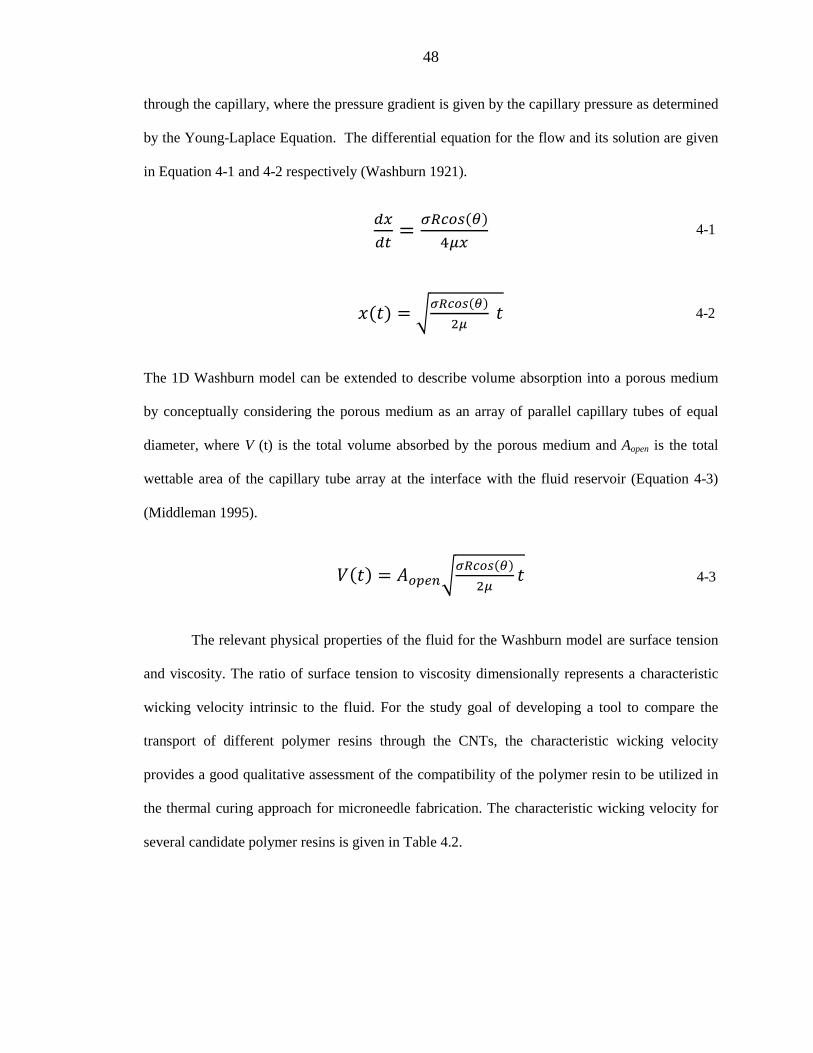
48
through the capillary, where the pressure gradient is given by the capillary pressure as determined
by the Young-Laplace Equation. The differential equation for the flow and its solution are given
in Equation 4-1 and 4-2 respectively (Washburn 1921).
𝑑𝑥𝑑𝑡
= 𝜎𝑅𝑐𝑜𝑠(𝜃)4𝜇𝑥
𝑥(𝑡) = �𝜎𝑅𝑐𝑜𝑠(𝜃)2𝜇
𝑡
The 1D Washburn model can be extended to describe volume absorption into a porous medium
by conceptually considering the porous medium as an array of parallel capillary tubes of equal
diameter, where V (t) is the total volume absorbed by the porous medium and Aopen is the total
wettable area of the capillary tube array at the interface with the fluid reservoir (Equation 4-3)
(Middleman 1995).
𝑉(𝑡) = 𝐴𝑜𝑝𝑒𝑛�𝜎𝑅𝑐𝑜𝑠(𝜃)
2𝜇𝑡
The relevant physical properties of the fluid for the Washburn model are surface tension
and viscosity. The ratio of surface tension to viscosity dimensionally represents a characteristic
wicking velocity intrinsic to the fluid. For the study goal of developing a tool to compare the
transport of different polymer resins through the CNTs, the characteristic wicking velocity
provides a good qualitative assessment of the compatibility of the polymer resin to be utilized in
the thermal curing approach for microneedle fabrication. The characteristic wicking velocity for
several candidate polymer resins is given in Table 4.2.
4-2
4-3
4-1
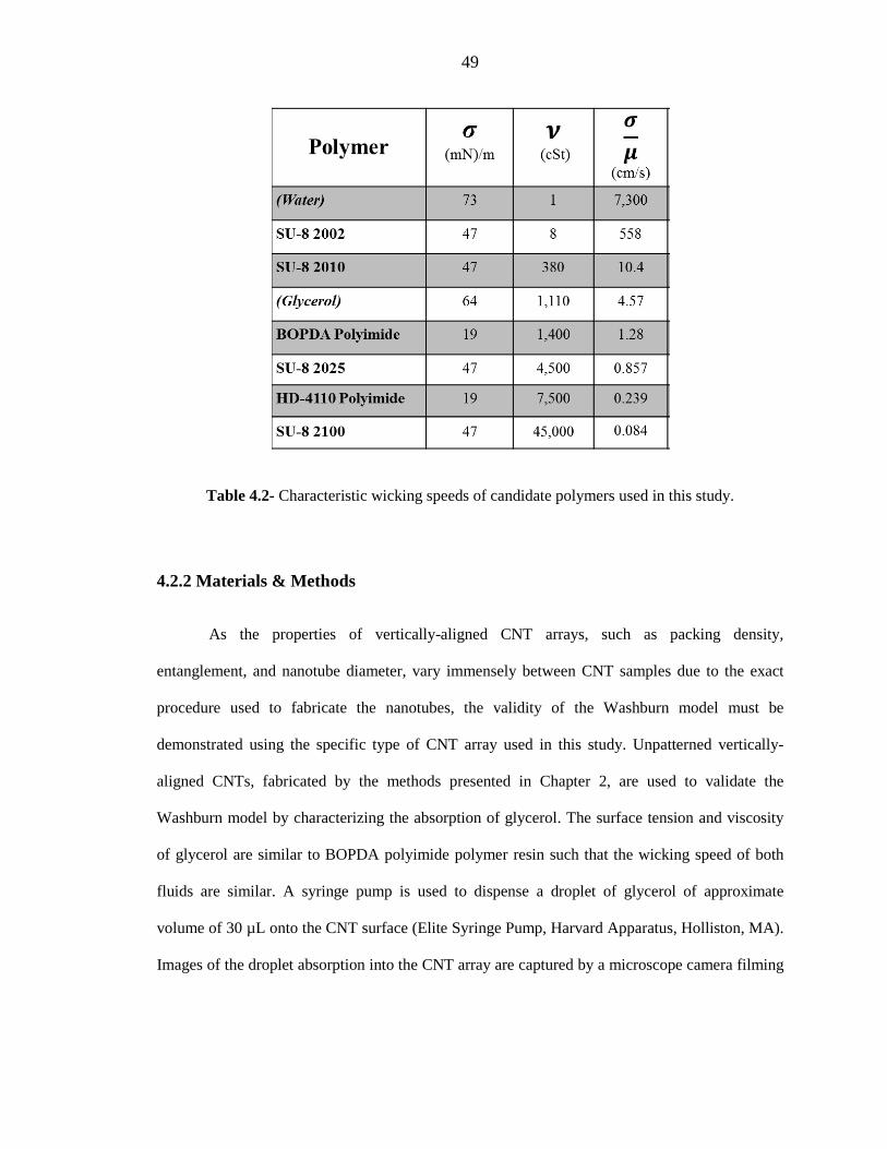
49
Table 4.2- Characteristic wicking speeds of candidate polymers used in this study.
4.2.2 Materials & Methods
As the properties of vertically-aligned CNT arrays, such as packing density,
entanglement, and nanotube diameter, vary immensely between CNT samples due to the exact
procedure used to fabricate the nanotubes, the validity of the Washburn model must be
demonstrated using the specific type of CNT array used in this study. Unpatterned vertically-
aligned CNTs, fabricated by the methods presented in Chapter 2, are used to validate the
Washburn model by characterizing the absorption of glycerol. The surface tension and viscosity
of glycerol are similar to BOPDA polyimide polymer resin such that the wicking speed of both
fluids are similar. A syringe pump is used to dispense a droplet of glycerol of approximate
volume of 30 µL onto the CNT surface (Elite Syringe Pump, Harvard Apparatus, Holliston, MA).
Images of the droplet absorption into the CNT array are captured by a microscope camera filming

50
at a frame rate of 30 frames per second (DCM Series Microscope Camera, ScopeTek, Hangzhou,
China).
The image stack from the droplet absorption is imported and processed in MATLAB. A
custom script converts the grayscale images of the droplet into binary images to allow for the
diameter and height of the droplet in each frame to be measured. The droplet is approximated as a
spherical cap to allow for calculation of the droplet volume in each frame (Equation 4-4).
𝑉 = 𝜋ℎ6
(3𝑟2 + ℎ2)
After contacting the surface of the CNTs, the diameter of the glycerol droplet remains constant
such that the extension of the Washburn equation to fluid volume (Equation 4-3) can be applied
to the data to determine if transport of polymer resin into the CNT array follows the Washburn
model.
4.2.3 Results
The absorption of glycerol droplets into unpatterned CNTs demonstrated good agreement
with the Washburn model, as determined by curve fit to the data (Figure 4.2). Thirty microliter
droplets of glycerol were fully absorbed by CNT samples on the order of seconds, allowing for
sufficient time resolution of the adsorption process. The volume of the spherical cap was
measured until the droplet regressed to a volume of approximately 30% of its original volume.
Beyond this point, the resolution of the camera and the spherical cap assumption prohibited
accurate measurement of the volume. The Washburn model also accurately predicts the time
when the droplet is fully absorbed. The experiment was repeated 40 times on different CNT
samples, and all cases showed good agreement with the Washburn model.
4-4

51
Figure 4.2 (a) Time-lapse images of glycerol droplet being absorbed into unpatterned CNT surface. (b) Representative glycerol droplet absorption data. Blue points represents experimental
data. Red line represents fit of data to Washburn model.
The data demonstrates that the transport of viscous fluids through the CNTs used in this
study can be modeled by the Washburn equation. This result was expected from previous fluid
transport studies through CNTs (Zhou 2005). However, validation is a necessary step considering
the wide range of catalyst preparations and CVD protocols that can be used to produce vertically-
aligned CNTs (Park and Lee 2012). Furthermore, the use of glycerol, which has a similar wicking
T= 0 s T= 0.25 s T= 0.5 s
T= 1 s T= 2 s T= 4 s
(a)
(b)
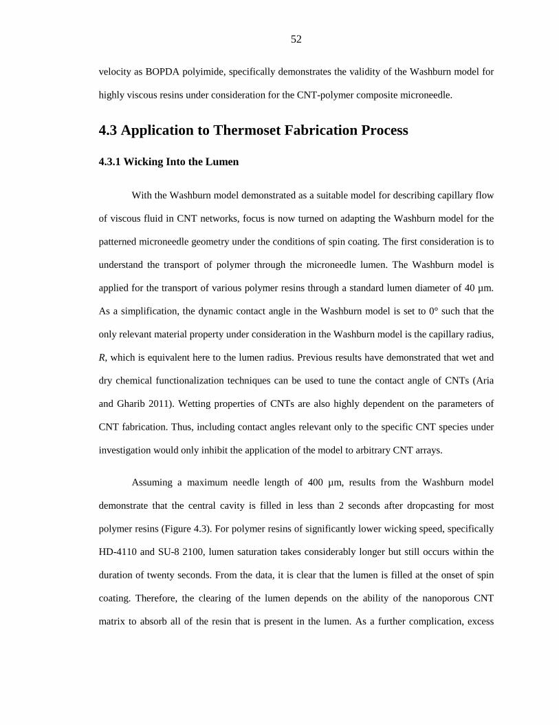
52
velocity as BOPDA polyimide, specifically demonstrates the validity of the Washburn model for
highly viscous resins under consideration for the CNT-polymer composite microneedle.
4.3 Application to Thermoset Fabrication Process
4.3.1 Wicking Into the Lumen
With the Washburn model demonstrated as a suitable model for describing capillary flow
of viscous fluid in CNT networks, focus is now turned on adapting the Washburn model for the
patterned microneedle geometry under the conditions of spin coating. The first consideration is to
understand the transport of polymer through the microneedle lumen. The Washburn model is
applied for the transport of various polymer resins through a standard lumen diameter of 40 µm.
As a simplification, the dynamic contact angle in the Washburn model is set to 0° such that the
only relevant material property under consideration in the Washburn model is the capillary radius,
R, which is equivalent here to the lumen radius. Previous results have demonstrated that wet and
dry chemical functionalization techniques can be used to tune the contact angle of CNTs (Aria
and Gharib 2011). Wetting properties of CNTs are also highly dependent on the parameters of
CNT fabrication. Thus, including contact angles relevant only to the specific CNT species under
investigation would only inhibit the application of the model to arbitrary CNT arrays.
Assuming a maximum needle length of 400 µm, results from the Washburn model
demonstrate that the central cavity is filled in less than 2 seconds after dropcasting for most
polymer resins (Figure 4.3). For polymer resins of significantly lower wicking speed, specifically
HD-4110 and SU-8 2100, lumen saturation takes considerably longer but still occurs within the
duration of twenty seconds. From the data, it is clear that the lumen is filled at the onset of spin
coating. Therefore, the clearing of the lumen depends on the ability of the nanoporous CNT
matrix to absorb all of the resin that is present in the lumen. As a further complication, excess

53
resin from the top of the microneedle at the beginning of spin coating continues to replenish the
lumen, making the lumen a nearly infinite reservoir. (Figure 4.4a).
Figure 4.3- Progression of polymer resin into 40 µm diameter lumen.
(a)
(b)

54
4.3.2 Effect of Spin
At the beginning of spin coating, the CNT scaffold is completely surrounded by polymer
resin (Figure 4.4a). The effective capillary diameter of the CNT scaffold for the Washburn model
is set to 30 nm, coinciding with the mean distance between nanotubes in the CNT scaffold. In
comparing the curvature of the 40 µm diameter lumen to a single CNT capillary tube of 30 nm
diameter, the capillary tube is small enough such that the interface between the lumen and the
capillary tube can be considered planar, as is assumed in the standard Washburn model presented
thus far. This argument can also be extended to the outer lateral surface of the microneedle such
that curvature of the microneedle does not need to be considered in the transport model through
the CNT matrix.
Spin coating is performed at constant angular velocity in the range of 1,000 – 3,000 rpm
depending on the polymer resin (see Section 3.2). Thus, a rotating reference frame can be used to
evaluate the forces on the microneedle and polymer resin. A Coriolis force is exerted on the
polymer resin. However, the Coriolis force acts only to push the fluid in the azimuthal direction,
causing no net effect to flow for an axisymmetric microneedle scaffold. In contrast, the
centrifugal force points in the outward radial direction with magnitude 𝜌𝜔2𝑟 which, in principle,
can act to aid capillary force in clearing polymer resin from the lumen.
Centrifugal force can be appended to the Washburn equation as a body force (Middleman
1995). For transport from the lumen into the CNT matrix, centrifugal force acts in the direction of
capillary transport (positive sign, Equation 4-5). For transport from the outer lateral surface of the
microneedle, centrifugal force acts against the direction of capillary transport (negative sign,
Equation 4-5).
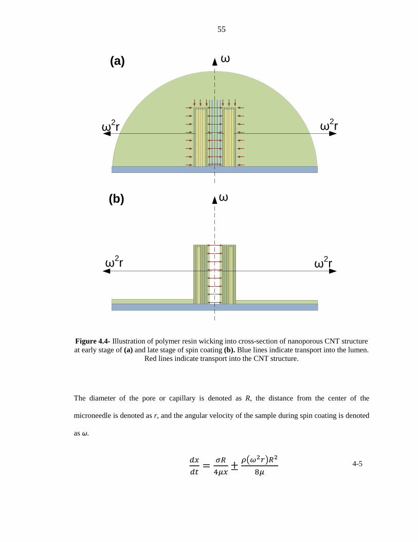
55
Figure 4.4- Illustration of polymer resin wicking into cross-section of nanoporous CNT structure at early stage of (a) and late stage of spin coating (b). Blue lines indicate transport into the lumen.
Red lines indicate transport into the CNT structure.
The diameter of the pore or capillary is denoted as R, the distance from the center of the
microneedle is denoted as r, and the angular velocity of the sample during spin coating is denoted
as ω.
𝑑𝑥𝑑𝑡
= 𝜎𝑅4𝜇𝑥
± 𝜌�𝜔2𝑟�𝑅2
8𝜇
ω
ω2r ω2r
(b)
ω
ω2r ω2r
(a)
4-5

56
In comparing the magnitude of the capillary and centrifugal terms, as a function of pore size, the
capillary term dominates the centrifugal term by more than 7 orders of magnitude. Figure 4.5
illustrates this for the case of BOPDA polyimide spin coated at 1,000 RPM, or 105 rad/s, being
wicked from the lumen into hypothetical CNT networks of varying capillary sizes, R.
Figure 4.5- Ratio of Capillary and Centrifugal Terms in Washburn Equation as a function of capillary size (Equation 4-5).
In the range of pore size for the CNT network used in this study, 15 nm pore radius, the capillary
term is 9 orders of magnitude higher than the centrifugal term. In generalizing this result for
different resins and larger spin speeds considered in the fabrication of microneedles, the result of
the centrifugal action being negligible compared to the Washburn capillary action is consistent.
Therefore, the action of wicking into the CNT network during spin coating can be represented by
the original Washburn equation (Equation 4-2).
R (µm)

57
This is a very important consideration, as it shows that the capillary action of polymer
resin through the CNTs is independent of spin speed. In terms of the fabrication process, this
result decouples the action of determining a polymer base thickness from the action of forming
the CNT-polymer composite through capillary action. From a polymer resin’s spin speed curve,
the spin speed alone can be used to determine the base thickness. Transport through the CNTs can
be characterized by the wicking velocity alone, the ratio of surface tension to viscosity of the
resin, to ensure proper setting of the CNT-polymer composite, including a clear lumen. This
criterion is still subject to the ultimate range of achievable spin coated film thickness, which is
determined by the physical properties of the fluid. However in practice, this criteria allows for
fine tuning of the base thickness over the spin speed curve without affecting the formation of the
CNT-polymer composite.
4.3.3 Limitations on Lumen Diameter
As described in the previous section, the lumen of the microneedle becomes filled in a
matter of seconds after dropcasting. In this same time span, the fluid front of the polymer resin
only advances 1-10 µm into the nanoporous network, depending on the resin’s wicking velocity.
As an additional consideration, in the early stages of spin coating, when excess resin still covers
the microneedle, the lumen is continuously being refilled, representing an almost infinite
reservoir (Figure 4.4a). Only in later stages of spin coating, when the excess polymer resin is
removed from the top surface of the scaffold, can the lumen begin to be emptied by transport
through the nanoporous network (Figure 4.4b). Therefore, the total amount of resin absorbed by
the CNTs through the lumen is potentially much more than the physical volume of the lumen.
The necessity to drain the volume of the lumen through the surface area of the lumen for
the thermal fabrication method places restrictions on the size of the lumen, since the ratio of
lumen volume to surface area is linear in diameter. This restriction was observed in a study of

58
three different microneedle designs. Each design had the same outer diameter, 150 µm, with a
varying lumen diameter of either 25 µm, 40 µm, or 75 µm. Each microneedle design was
incorporated with BODPA polyimide using the same thermal fabrication protocol as described in
Section 3.2.2.2. After fabrication, the lumen was observed for blockage at both the top and the
bottom of the needle through SEM imaging (Figure 4.6). The lumen was clear for the
microneedles with lumen diameters of 25 µm and 40 µm. Additionally, the open lumen for these
designs was verified by fluid delivery experiments, as will be discussed in Chapter 5. For the
microneedle with a 75 µm lumen, inspection of the bottom of the needle reveals a clogged lumen.
Figure 4.6- Matrix of different lumen diameters showing lumen obstruction for larger lumen diameters. While capillography shrinks the body of the microneedle above the polymer base, the
bottom of the microneedle imbedded in the polymer base retains its original dimensions.
The fitness of a microneedle geometry for being able to absorb the resin flowing into the
lumen can be determined by the ratio of the open volume in the microneedle to the lumen
150/25 150/40 150/75
95/20 95/30 95/50
CNT Scaffold
CNT- BOPDA Polyimide
Microneedle
Underside of CNT- BOPDA
Polyimide Microneedle
Outer/Lumen Diameter (µm)
Ratio of Scaffold Volume to Lumen
Volume32 12 2.7

59
volume. Assuming an approximate open area fraction of 90% for the CNT scaffold, the ratio of
open scaffold volume to lumen volume is 32, 12, and 2.7 for the 25 µm, 40 µm, and 75 µm
diameter lumens respectively. In the early stages of spin coating, it is expected that polymer resin
wicks into the scaffold structure from the entire scaffold surface area (Figure 4.4a). Therefore, it
is assumed that the scaffold to lumen volume ratio must be sufficiently higher than 1 to
accommodate wicking from all surfaces, while still allowing the lumen to be completely cleared
in the later stages of wicking, when the lumen becomes the only active wicking surface.
The dependence of the thermal fabrication process on passive fluid transport ultimately
limits the maximum size of the lumen for a given outer needle diameter. For fluid delivery
through the microneedle, lumen diameter represents a potentially critical parameter, as the
volumetric flow rate through the needle scales with lumen diameter to the fourth power for
Poiseuille flow. Chapter 5 will investigate further, in the context of delivery, the constraint lumen
size has on deliverable volume into the skin for transdermal drug delivery. In order to circumvent
this restriction on lumen diameter, the selective UV curing method presented in Chapter 3 would
have to be utilized, as it provides for an active method for clearing the lumen.
4.3.4 Capillary Action Through the CNT Scaffold
Wicking from the outer surface of the microneedle is quickly extinguished as the polymer
resin droplet is spread across the substrate in the first few seconds of spin coating. Thus, for the
majority of the duration of spin coating, wicking from the central cavity is the dominant transport
direction (Figure 4.4b). Transport of polymer resin from the lumen through the CNT scaffold as
characterized by the Washburn model is presented in Figure 4.7 for various candidate polymer
resins. The duration of the dropcasting and spin coating step is sixty seconds for all resins. After
that, the sample is transferred onto a hot plate to begin curing the polymer resin. The progression
of the fluid front during this time, as predicted by the Washburn model, is used as an indication of

60
the ability of the resin to fully envelop the CNT scaffold during spin coating, leading to the
clearing of the microneedle lumen. The Washburn model describes flow in an infinitely long
capillary. In practice, the thickness of the needle ranges from 55 – 63 µm depending on the
specific design. Therefore, for fluid front positions greater than the microneedle thickness, it is
assumed that the resin fully envelops the CNT scaffold.
Figure 4.7- (a) Fluid Front vs. Time for CNT scaffold with effective capillary diameter of 30 nm. (b) Position of Fluid Front at end of Spin Coating for each polymer. Error bars represent effect of
uncertainty in the effective capillary diameter of the CNT scaffold.
(a)
(b)
SU-8 2100
HD-4110
SU-8 2025
BOPDA
(Glycerol)
SU-8 2010
SU-8 2002
0 200 400 600 800 1000 1200 1400 1600 1800 2000 2200
Position of Fluid Front at End of Spin Coating (µm)
Poly
mer
19
33
62
76
143
217
1,585

61
Polymers with a very high wicking speed, such as SU-8 2002 and 2010, with wicking
speeds of 558 cm/s and 10.4 cm/s respectively, can completely penetrate the thickness of the
microneedle with predicted fluid fronts at the end of the spin coating cycle greater than the
thickness of the microneedle. While these polymers are adept for forming the CNT–polymer
composite, their overall low viscosity does not allow for the formation of a thick base via spin
coating, as required by the general microneedle requirements. Glycerol has a suitable wicking
speed for penetrating the CNT scaffold. However, glycerol is not a thermoset resin and cannot be
used directly to form a composite structure. In the other extreme, polymer resins with very low
wicking speed, such as SU-8 2100 and HD-4110, do not allow for sufficient transport into the
CNT scaffold to allow for the lumen to be cleared passively. Specifically for SU-8 2100, with a
predicted fluid front of only 19 µm after spin coating, the lumen is completely clogged, as can
been seen from both the top and the bottom of the microneedle. Thus, these resins are only
capable of being incorporated into the CNT-polymer microneedle by using the UV fabrication
process.
BOPDA polyimide and SU-8 2025 both have predicted fluid fronts in the range of the
thickness of the microneedles. Therefore, both polymers are qualitatively predicted to fully
envelop the CNT scaffold, providing for the proper conditions for clearing the lumen of resin.
Furthermore, the spin speed curves of both resins demonstrate the capability to generate a base of
sufficient thickness to support the microneedle array structure. Experimentally, BOPDA
polyimide has consistently demonstrated the ability to clear the lumen. Overall, SU-8 2025
showed mixed results when being processed through a thermal fabrication cycle. A few
microneedle array samples showed clear lumen, while the majority of samples demonstrated a
clogged lumen as observed by inspection of the lumen on the underside of the microneedle.
The Washburn model, in general, represents an optimistic look at the ability of polymer
resin to wick through the CNT scaffold. By modelling the CNTs as a parallel bundle of equal

62
sized capillary tubes, secondary effects, such as tortuosity, that can impede the transport rate are
neglected. Previous work has also demonstrated that for porous media with a distribution of
capillary sizes, like CNTs, that the Washburn model overestimates the transport rate as the media
approaches saturation (Zhou 2005). This is because in a porous media, larger capillaries are filled
at a faster rate than smaller capillaries such that near saturation, the global transport rate is
determined solely by transport through smaller, more resistive capillaries. Results presented here
approximate the effective capillary diameter as the mean interspacing between nanotubes for the
CNT scaffold. In considering VA-CNTs from different sources and fabrication methods, the
mean interspacing between nanotubes from generic VA-CNT samples can vary greatly. In
considering an uncertainty of 20 nm for the 30 nm capillary diameter, the total transport length of
the fluid front during spin coating has a maximum uncertainty of 33%, as visualized in Figure
4.7b.
In applying the thickness of the microneedle as a prerequisite transport distance for
forming the composite needle with a clear lumen, the Washburn model can finely differentiate
between the performance of resins with similar wicking speeds such as SU8-2025 and BOPDA
polyimide, with wicking speeds of 1.28 and 0.857 cm/s respectively. From these results, a
screening criterion can be established, for the microneedle geometry under investigation, that a
polymer resin must have a wicking speed greater than 1 cm/s in order to be a suitable candidate
for incorporation through the thermal fabrication process (Table 4.3).

63
Table 4.3- Wicking speeds of candidate polymers used in this study. A wicking speed greater than 1cm/s is required for a polymer to be used in the thermal curing technique. This criteria is
verified by experimental observation summarized in the last column.
4.4 Conclusions
The thermal curing method for fabricating CNTs relies on passive capillary action to
clear the lumen and infiltrate the CNT scaffold to form the CNT-polymer composite.
Understanding the underlying fluid mechanics behind this capillary transport is critical in order to
apply this simple, passive fabrication method to a wide range of polymers to improve the utility
of the CNT-polymer composite microneedle concept. Fluid absorption experiments performed on
unpatterned CNTs demonstrated that the capillary action of viscous polymer resins or fluids can
be described by the Washburn model of capillary action.
In applying the Washburn model to the geometry of the microneedles under the
conditions of spin coating, it was shown that the contribution of Washburn capillary action
dominates the transport of polymer resin into the CNT scaffold, neglecting any centrifugal

64
contributions from spinning. The ability to clear the lumen using capillary action was shown to
ultimately place an upper limit on the size of the lumen relative to the thickness of the
microneedle. For the 150 µm outer diameter microneedle under investigation in this study, it was
shown that the lumen cannot be passively cleared through capillary action for lumen diameters
greater than 75 µm. To overcome this limitation, the thermal curing method must be substituted
for the UV curing method, which allows for the lumen to be actively cured through a wet
development process.
The rate of capillary transport in the Washburn model scales with a characteristic wicking
velocity, which is an intrinsic property of the polymer resin. The characteristic wicking velocity is
equal to the ratio of surface tension to viscosity for a fluid, which has the equivalent unit of
velocity. While the wicking velocity itself is not an accurate assessment for the actual fluid speed,
the wicking velocity can act as a quantitative indicator of whether or not a particular polymer
resin can be utilized for the thermal curing fabrication technique. For the specific geometry
investigated in this study, 150 µm outer and 40 µm luminal diameter, it was determined that a
wicking velocity greater than 1 cm/s is necessary to achieve a clear lumen after spin coating.
With the inclusion of the results from the polymer resin transport analysis, Table 4.1
presents a complete list of microneedle requirements and the corresponding selection criteria for
choosing a polymer. With the addition of the wicking velocity criteria for the thermal curing
method, all of the polymer selection criteria consist of simple material property data such as
surface tension, stiffness, and spin speed curves. Thus, these criteria can be applied to any general
thermoset polymer for thermal curing or negative photoresist for selective UV curing to
determine whether the polymer is an appropriate match for forming the CNT-polymer composite
microneedle. This set of requirements eliminates the underlying empirical nature of forming the
composite, as presented in Chapter 3, and can allow for wider adaptation of the technology.

65
Chapter 5
Laboratory and In Vitro Delivery
5.1 Introduction
From the fabrication methods presented in Chapter 2, two microneedle architectures were
deemed suitable to proceed to the stage of incorporation onto a delivery platform by assessing the
ability of each microneedle architecture to reliably satisfy the fabrication requirements. The two
microneedle architectures chosen were CNT-SU8-2025 and CNT-BOPDA polyimide. Each
microneedle has an outer diameter of 150 µm and a height between 200-250 µm. The CNT-SU8
microneedles have a lumen diameter of 25 µm, and the CNT-BOPDA microneedles have a lumen
diameter of 30 µm.
Here, it is demonstrated that the CNT-polymer microneedles have the capability to
successfully deliver aqueous dye using two delivery mediums: hydrogel and in vitro swine skin.
Additionally, before testing in a delivery medium, the performance of the microneedles is
assessed by passing fluid through the microneedles without a delivery medium (delivery into the
air) to verify that the polymer base and microneedles are leak-proof. Focus in these experiments
is given on the physical aspects of delivery, including the ability of the microneedles to penetrate
skin and the ability of the microneedles to conduct fluid into the skin.

66
The goals of these experiments are to:
• Demonstrate that the CNT-polymer composite microneedles can function as a
microneedle, as indicated by successful in vitro skin penetration and fluid delivery.
• Demonstrate the compatibility of CNT-polymer composite with different drug delivery
platforms.
• Assess the performance the combined system of the CNT-polymer microneedles with a
given drug delivery platform.
Of particular importance is to understand how the delivery results are influenced
separately by the microneedles and the drug delivery platforms supporting the microneedles.
Several drug delivery platforms are investigated, including syringes and band-aid style skin
patches. Fluid is driven through these platforms by either hand actuation or actuation by a syringe
pump.
A hand actuated band-aid style skin patch is envisioned as the optimal delivery method.
Hand actuation simplifies the design of the skin patch by reducing costs and eliminating power
requirements associated with an electric pump, and works towards the universal goal of
microneedle technology to broadly disseminate medicine without the assistance of medical
infrastructure and personnel. Here, development of the hand actuated skin patch is considered in
parallel to the development of the CNT-polymer microneedles in order to build a complete drug
delivery system.
5.2 Materials & Methods
5.2.1 Delivery Platforms
Several delivery platforms are utilized to characterize delivery through the microneedles,
as well as to demonstrate the adaptability of the CNT-polymer microneedles to be incorporated
67
into several delivery architectures. In this section, a detailed description of the fabrication and the
utility of each delivery platform is presented.
5.2.1.1 Dye Coated Microneedles
The first delivery platform considered is a microneedle coated with dye. The purpose of
this arrangement is to assess the ability of the microneedles to penetrate skin separately from the
ability to deliver fluid. In this way, the mechanical strength of the pillar can be assessed
separately from the fluid transport properties of the microneedle.
For this experiment, microneedles were kept on their native silicon substrate. The
microneedles and silicon substrate were attached to a 1” x 3” glass slide with double-sided copper
tape. A dye solution of methylene blue and chloroform was prepared and poured over the
microneedle array (Sigma-Aldrich, St. Louis, MO). Upon evaporation of the chloroform, dry
methylene blue powder conformally coated the microneedles. During in vitro skin penetration,
the methylene blue powder is reconstituted into a dye upon contact with the interstitial fluid from
the skin. Concentrated pockets of dye in the skin are then identified as penetration marks.
5.2.1.2 Modified Syringe
An adapter was placed on a standard 3 mL hypodermic syringe to support delivery
through a microneedle array. Figure 5.1 demonstrates an example of a CNT-SU8 microneedle
array placed upon an adapter assembly used to connect the microneedles to the syringe (not
pictured). This approach has been used in previous microneedle studies such that the simplicity of
the delivery platform allows for focus on the delivery capabilities of the microneedle as well as
use of a syringe pump to precisely actuate the flow (Stoeber and Liepmann 2005) (Norman et al.
2013).

68
Figure 5.1- Modified syringe platform for microneedle drug delivery.
The microneedle array is glued to a hard plastic reservoir adapter using a quick cure
epoxy (Idex Health & Science, Odex Harbor, Washington). The reservoir adapter has an open
cavity diameter of approximately 3 mm on its top surface, allowing for actuation of a maximum
of 9 microneedles. The rest of the microneedles are adhered directly to the top surface of the
reservoir and cannot be filled with fluid. The reservoir adapter is fitted to a piece of clear plastic
tubing. The tubing is fitted to a hypodermic syringe with a barb-luer lock adapter. Actuation is
achieved by either a syringe pump or manual forcing of the syringe.
5.2.1.3 Single Reservoir Skin Patch
PDMS (polydimethylsiloxane) skin patches were constructed as an additional delivery
platform for investigating drug delivery through CNT-polymer microneedles. PDMS is chosen as
the material as its soft, flexible properties resemble that of a band-aid. In this sense, a PDMS skin
patch represents a platform that can potentially allow for patient administration without direct
medical supervision from a nurse or doctor. The first PDMS skin patch constructed is based on a
single drug reservoir, hand actuated design. Designs of this type have been utilized in previous
conceptions and studies (Gharib, Sansom, and Aria 2010) (Häfeli et al. 2009).
A single reservoir skin patch was designed specifically for use with the CNT-polymer
microneedles. The skin patch is 3.4 cm in diameter, with a thickness of 0.5 cm (Figure 5.2 a,b).

69
The microneedles are connected to the PDMS patch using the same reservoir adapter as in the
modified syringe design such that the microneedles can be interchanged on the reservoir during
experiments. The microneedles sit directly below the drug reservoir (Figure 5.2 c).
Figure 5.2- Single Reservoir Skin Patch. (a) Image of the single reservoir skin patch with CNT- SU8 microneedles. (b) The single reservoir skin patch with CNT- SU8 microneedles placed on the forearm to illustrate scale in handling and placing the patch. (c) Cross-section schematic of
the components and operation of the single reservoir skin patch.
A thin PDMS membrane, of 2 mm thickness, covers the drug reservoir such that by squeezing the
cover actuates flow through the microneedles. The drug reservoir has a top diameter of 1.5 cm to
allow for actuation with a single finger. The dimensions of the skin patch are selected in order to
emulate a band-aid in terms of handling and wearability. The large size of the skin patch
compared to the minute dimensions of the microneedles is designed to ensure the skin patch is
universally accessible to patients for the goal of self-administration, particularly for patients with
impaired coordination.
The drug reservoir is filled through a channel that runs underneath the PDMS cover to the
side of the patch. A barb-luer lock adapter at the end of the channel allows for the patch to be
Deformable Cover
FDeliveryFApplication
Skin Patch
Drug Reservoir
Syringe Adapter
Microneedle Array
Nanoport
(a)
(b) (c)

70
filled by a hypodermic syringe. Additionally, a check valve is placed in between the barb-luer
lock adapter and the syringe to prevent backflow (Qosina, Edgewood, New York). Alternatively,
the check valve can also be replaced with a luer lock cap during delivery.
To fabricate the skin patch and deformable cover, molds were machined out of acetal
plastic using a CNC mill (CNC Mini-Mill 3, Minitech Machinery Corporation, Norcross,
Georgia). PDMS resin (Sylgard 184, Dow Corning, Midland, MI) was poured into the molds and
then set thermally at 80°C in a convection oven for 1 hour. After removing the components from
their respective molds, the cover was attached to the skin patch by using PDMS resin as an
adhesive and thermal curing at 80°C in a convection oven for 30 minutes. Similarly, the barb-luer
lock adapter was set in the skin patch using PDMS resin as an adhesive element.
5.2.1.4 Dual Reservoir Skin Patch
A second PDMS skin patch was designed utilizing two drug reservoirs connected in
series (Figure 5.3). The primary drug reservoir is offset from the microneedles and holds the
majority of the drug. (Figure 5.3 d) The primary drug reservoir is covered by a thin, highly
deformable silicone (EcoFlex 30 Smooth-On, Easton, PA) to allow the drug release into the skin
to be actuated by pressing on the top of the reservoir akin to the single reservoir patch. A small
secondary reservoir sits directly above the microneedles to ensure a continuous flow of drugs into
the microneedles. The two reservoirs are connected to each other through a small channel within
the patch.
The purpose of using an offset drug reservoir is to separate the action of applying the
microneedles to the skin and actuating drug delivery. By using a two-step approach, the chance of
accidental drug discharge while applying and removing the microneedles is significantly reduced.
This is especially important for making the microneedles universally accessible to patients for

71
Figure 5.3- Dual Reservoir Skin Patch with CNT-BOPDA Microneedles. (a) Skin patch fits within a person’s palm. The CNT-BOPDA microneedles are adhered directly to the skin patch.
(b) Skin patch filled with aqueous methylene blue solution to illustrate the flow path. (c) Application of microneedles onto the forearm with actuation of the primary drug reservoir. (d)
Fabrication schematic of skin patch. (e) Cross section schematic of components and operation of skin patch.
self-administration. Particularly for patients with impaired coordination, the two-step approach
allows for adjustment in placing the patch before committing to drug delivery. The size of the
skin patch is designed specifically such that the delivery can be achieved by using two fingers.
(1) Plasma Bond
(2) EcoFlex Adhesive
(3) PDMS Adhesive
(4) PDMS Adhesive
SKIN PATCH (BOTTOM)
SKIN PATCH (TOP)
MICRONEEDLE ARRAY
COVER
SYRINGE ADAPTER
Secondary Drug Reservoir
Microneedle Array
Skin Patch
Deformable Cover
Primary Drug Reservoir
FDelivery FApplicationSyringe Adapter
(a)
(d)
(b)
(e)
(c)
72
The first finger presses down directly on top of the microneedle to achieve skin penetration. The
second finger then presses on the primary drug reservoir to actuate the flow of drug. The overall
skin patch is 3.6 cm x 3.6 cm, with a thickness of only 3 mm. In contrast to the single reservoir
skin patch, the microneedles in the dual reservoir skin patch are attached directly to the skin patch
using uncured PDMS as an adhesive. In this way, the flexibility of the polymer base of the
microneedles directly complements the flexibility of the PDMS, allowing for local deformation
during skin penetration to improve skin contact.
The components and fabrication steps of the skin patch are illustrated in Figure 5.3d. The
patch is constructed from two PDMS layers that are bonded together to create the reservoirs. A
thin layer of highly deformable silicone (EcoFlex 30) is then added as a cover. As before for
fabricating the PDMS and EcoFlex layers, the resins were poured into micromachined acetal
plastic molds. Each material was thermally cured in a convection oven at 80°C for up to 1 hour.
The two separate PDMS layers were bonded together after a remote oxygen plasma
surface treatment of 100 sccm oxygen at 500 W and 200 mTorr for 5 minutes (PVA Tepla M4L
Gas Plasma System, Corona, CA). After the surface treatment, the PDMS layers were pressed
together under a constant pressure of approximately 10N, and placed in a convection oven at
80°C for 30 minutes to form the bond (1). To attach the cover, a small amount of EcoFlex resin
was brushed onto the PDMS surface as an adhesive. After placing the cover on top of the skin
patch, the assembly was again placed in a convection oven at 80°C for 30 minutes to set the
Ecoflex resin (2). Similarly for attaching the microneedle array and the syringe adapter to the skin
patch, PDMS resin was used as an adhesive and allowed to set in an 80°C convection oven for 30
minutes (3,4). A standard syringe is used to fill the skin patch via the syringe adapter, a small
luer lock adapter connected to the side of the patch. During experiments, the syringe adapter is
capped to prevent backflow.

73
5.2.1.5 Syringe Pump Skin Patch
A skin patch based on the dimensions of the dual reservoir design was designed
specifically for actuation by an external syringe pump (Elite Syringe Pump, Harvard Apparatus,
Holliston, MA) through the syringe adapter (Figure 5.4). The similarity in design to the dual
reservoir skin patch is to directly isolate the effect of hand actuation versus external pump
actuation on the microneedle delivery. The modified patch consists of a single reservoir placed
above the microneedles using the same area dimensions as the secondary reservoir on the dual
reservoir patch. A thick PDMS cover is used in substitution of the flexible EcoFlex cover to
prevent any deformation of the patch during syringe pump actuation. The combined thickness of
the patch and cover is 7 mm. The skin patch is connected to a T-junction connected to tubing
from the syringe pump, as well as a drain that allows for an accelerated flow rate while filling the
tubing without risking damage to the skin patch.
Figure 5.4- Syringe pump skin patch attached to T-junction via luer lock connection.
5.2.1.6 Impact Penetration
Similar to the modification to the Syringe Pump Skin Patch in Section 5.2.1.5 to assess
the difference between hand actuation and pump actuation in microneedle delivery, a spring-

74
loaded applicator is considered here as an alternate to using hand force to press the microneedles
into the skin to achieve skin penetration. Previous work examined the effect of penetration speed,
or impact, on delivery of hollow microneedles of length between 200 and 300 µm. It was shown
that by substituting manually driven penetration for high impact penetration driven by an external
applicator, the delivery rate can be significantly raised by over an order of magnitude (Verbaan et
al. 2008).
For these experiments, the Syringe Pump Skin Patch was used in order to precisely
measure the delivery rate. The Syringe Pump Skin Patch was placed directly above the delivery
medium. The tip of the microneedle was placed within 2 mm of the top surface of the delivery
medium. An aqueous 1% methylene blue solution was used as the injected fluid in order to
visually assess the spread of delivered dye.
To provide the actuation force, a lancing device designed for obtaining blood samples for
glucose monitoring in diabetes patients was utilized (FreeStyle Lite Lancing Device, Abbott
Laboratories, Abbott Park, Illinois). In standard practice, the lancing device presses a metal
needle of a few millimeters in length into a patient’s skin to draw blood to be collected on a
glucose test strip. The metal needle sits upon a flat plastic plunger. The metal needle was
removed from the lancet such that the plunger could be used to contact the skin patch directly
above the microneedles (Figure 5.5).
The lancing device was placed directly over the microneedles on the skin patch (Figure
5.5). The plunger of the lancing device was modified to provide a flat area to provide an evenly
distributed force over the microneedle array. The surface area of the plunger was approximately 3
mm x 3mm, slightly larger than a 3 x 3 microneedle array. A button on the lancing device
releases the compressed spring and presses the plunger into the skin patch at a velocity of 2 m/s,
which in turn pushes the microneedles into the delivery medium. The penetration velocity
investigated here is consistent with previous studies that examined penetration speeds of 1 m/s

75
and 3m/s (Verbaan et al. 2008). After penetration, the lancet is left engaged to continue providing
steady force to keep the microneedles engaged in the delivery medium. Immediately following
penetration, the syringe pump was actuated to begin fluid flow. Delivery was sustained over 5
minutes, at constant flow rate.
Figure 5.5- Impact Penetration Setup. Lancing device sits above the Syringe Pump Skin Patch. Upon actuation, microneedles are driven into hydrogel (4% agarose) as a laboratory model for
skin.
5.2.2 Delivery Mediums
5.2.2.1 Into the Air
A combination of three delivery mediums are used in conjunction with the above delivery
platforms to assess the performance of the CNT-polymer microneedles. The first delivery
medium tested is no delivery medium. Fluid is simply flowed through the microneedles and is
expelled into the air. This is used as a baseline assessment to check for several conditions:
• Ensure that the lumen of the microneedles is not obstructed.
• Verify there is no defect in the microneedles, such as a tear in the polymer.

76
• Verify there is no leak in the skin patch, or defect in the connection between the
microneedles and the skin patch.
• Quantify the maximum flow rate through the microneedle-delivery platform system.
Delivering fluid into the air represents an opportunity to evaluate the hydraulic resistance of the
microneedles independently of any additional resistance contributed by the delivery medium. In
this way, it is assessed whether the lumen size and the number of microneedles are sufficient to
allow for an acceptable volumetric flow rate under the pressure limitations imposed by utilizing
hand actuation.
5.2.2.2 Hydrogel
Hydrogel is made in different concentrations of agarose ranging from 1% to 4%
(UltraPure Agarose, Life Technologies, Grand Island, NY). Hydrogel is used for testing fluid
delivery of the microneedle-delivery platform system separate from assessing the strength of the
microneedles for achieving skin penetration. In this way, delivery in hydrogel is complementary
to the dye coated microneedles in providing a platform to test specific aspects of the delivery.
Hydrogel can be easily penetrated with the microneedles. Because of the ease of penetration,
microneedles can be used for multiple delivery events into hydrogel. In contrast, as will be
discussed in Section 5.4.2.3, microneedles can only be used once for delivery experiments into
skin.
4% agarose hydrogel is found to be a good laboratory model for skin in terms of
comparable hydraulic resistance. Hydrogel is commonly used here in place of skin samples in
delivery experiments due to its high availability and quick preparation time. Delivery of an
aqueous solution of methylene blue dye is used to visualize the delivery and assess whether dye is
fully delivered into the hydrogel or spills over onto the surface of the gel.

77
5.2.2.3 In Vitro Swine Skin
Swine skin is used to represent human skin to assess the microneedle-delivery platform
system in actual delivery conditions. Previous studies have shown swine skin is similar to human
skin in terms of permeability and thickness (Marro, Guy, and Begoña Delgado-Charro 2001;
Schmook, Meingassner, and Billich 2001; Takeuchi et al. 2011). Skin samples were collected
from the dorsal region of four month old Yucatan Miniature Swine (Sinclair Bio Resources,
Columbia, MO). Skin samples were shaved prior to harvesting and kept frozen at -20°C until use,
for a maximum period of 12 weeks. Prior to use, frozen skin samples were placed in a sealed
plastic bag and thawed in a room temperature water bath. Extraneous fat from the underside of
the sample was removed with a straight edge chef’s knife.
Full-thickness skin samples were used with the CNT-BOPDA microneedles. A hole
punch was used to create uniform sample sizes of 38 mm diameter. Split-thickness skin samples
were used with the CNT-SU8 microneedles. To create split-thickness samples, full-thickness skin
samples were placed in a dermatome, which removes the bottom layers of the skin to produce a
sample less than 0.5 mm thick consisting of the stratum corneum, epidermis, and upper dermis
layers of the skin. During delivery, samples were placed on a glass slide and stretched taut to
ensure good contact with the microneedles during delivery.
Similar to delivery experiments performed in hydrogel, an aqueous solution of methylene
blue dye is used to visualize the delivery and assess whether dye is fully delivered into the skin or
spills over onto the surface of the skin. Microneedles can only be used once for skin penetration
experiments, as the microneedles tend to collect various oils and debris from the skin that can
occlude the lumen or block the microneedles from properly contacting the skin.

78
5.2.3 Imaging
The resulting injection sites from both the hydrogel and swine skin experiments were
imaged immediately after delivery using a stereomicroscope (Zeiss Stereo Discovery V20, Carl
Zeiss Microscopy, Jena, Germany). Microneedles were imaged by scanning electron microscopy
before and after skin delivery experiments to assess any structural damage.
5.3 Poiseuille Flow Model for Microneedle and Delivery
Platform System
Flow actuated from the delivery platform, through the microneedles, and into a resistive
delivery medium can be modelled as Poiseuille flow for steady microfluidic flows. Since the goal
of the study is to evaluate the delivery volume and volumetric flow rate, the parabolic velocity
profile predicted by Poiseuille flow can be integrated to give a 1D equation for volumetric flow
through the system (Equation 5-1).
𝜟𝑷 = 𝑸�𝟖𝝁𝑳𝝅𝒓𝟒
�
where Q is the volumetric flow rate, ΔP is the applied pressure, µ is the fluid viscosity, L is the
channel length, and r is the channel radius.
A helpful analogy for designing microfluidic flow systems is to consider Equation 5-1 as
an Ohm’s law for microfluidics (Kirby 2010). Applied pressure is equivalent to voltage and
volumetric flow rate is akin to current. Hydraulic resistance, R, can then be extracted from
Equation 5-1 as shown in Equation 5-2.
𝜟𝑷 = 𝑸𝑹
𝑅 =8𝜇𝐿𝜋𝑟4
5-2
5-1

79
The exact form of hydraulic resistance given in Equation 5-2 physically represents flow through a
cylindrical channel like the lumen of the microneedles. For other flow channel geometry, the
hydraulic resistance can be considered as an equivalent resistance to a cylindrical channel.
A flow circuit diagram for the microneedle delivery system is shown in Figure 5.6a for an
arbitrary number of microneedles, N. Since the microneedle geometry is consistent for each
needle, the circuit diagram can be simplified by the circuit relation for parallel resistors (Figure
5.6b). Adding the resulting resistances in series gives a total resistance for the system. All
delivery experiments considered here will consist of nine microneedles (N=9). From this
simplification, it is observed that the resistance of the system can be steadily decreased by the
addition of more microneedles. In comparing the size of the microneedle lumen to the millimeter
sized channels of the delivery platforms described in Section 5.2.1, the resistance of the delivery
platform can be neglected, since resistance scales inversely with channel diameter to the fourth
power.
Figure 5.6- (a) Hydraulic circuit representation for microneedle delivery system into a delivery medium for N identical microneedles. (b) Simplified circuit representation for identical parallel
microneedles. Additional microneedles lower system delivery resistance.
Rdelivery platform
Rmicroneedle
Rdelivery medium
ΔP
... ... ... ...Rdelivery platform
Rdelivery medium
ΔP
Rmicroneedle
N
(a) (b)

80
For the express application here, this model is used as a tool for considering the separate
contributions the skin patch, microneedles, and delivery medium play in resisting fluid flow.
Moving forward, the primary sources of hydraulic resistance that will be considered are the
microneedles and the delivery medium, while the delivery platform provides the actuation
pressure. Minimizing hydraulic resistance is a key design criterion for hand actuated delivery
systems. Hand actuation, in practice, limits the total pressure that can be applied to the flow
system. With this cap on the maximum applied pressure, minimizing hydraulic resistance is
required to ensure proper flow rates can be achieved.
5.4 Delivery Results
The delivery goals for the CNT-SU8 2025 microneedle were different from the goals for
the CNT-BOPDA polyimide microneedle. The CNT-SU8 microneedle was the first successful
microneedle to be fabricated. The delivery goals for the CNT-SU8 architecture were to separately
demonstrate the ability to achieve skin penetration and to conduct fluid through the array via hand
actuation.
After these experiments, the focus of the delivery experiments shifted to the newly
developed CNT-BOPDA microneedles. The thermal curing approach for the CNT-BOPDA
microneedle allowed for microneedles to be fabricated more rapidly, and was seen as being the
most advantageous for supporting delivery experiments on the laboratory stage thru in vivo
testing. Delivery experiments for the CNT-BOPDA microneedle continued where the
experiments with CNT-SU8 microneedles ended. The goal of the CNT-BOPDA delivery
experiments was to show that the CNT-BOPDA microneedles combined with a hand actuated
skin patch can allow for fluid delivery into in vitro skin. In this manner, these experiments
combined the solid mechanics requirement of penetrating skin with the fluid mechanics
requirement of supporting fluid conduction through the microneedle.

81
5.4.1 CNT-SU-8 2025 Microneedle
Figure 5.7- Delivery into the air for CNT-SU8 microneedle. (a) Modified syringe with total array flow of 4.8 mL/min. (b) Flow through single reservoir skin patch under hand actuation.
Liquid flow through the microneedle is demonstrated by connecting the microneedle
array to a water filled modified syringe. Despite the small 25 µm lumen diameter per needle, the
integrated area of the microneedle array allows for high flow rates into the air of 4.8 mL/min for
the array under hand actuation (Figure 5.7a). Despite the relatively thin polymer base of
approximately 25 µm, the base shows no signs of fatigue or cracking under high flow rates.
Achieving flow greater than 600 µL/min per needle under minimal actuation pressure
demonstrates the low hydraulic resistance of the device, which ultimately lowers the work needed
to flow liquid through the microneedles at any flow rate. CNT-SU8 microneedles were
incorporated into the single reservoir skin patch. Flow was actuated by pressing a single finger
into the deformable cover (Figure 5.7 b). To actuate flow, the applied force was exceedingly
gentle, with a magnitude of less than 1N. Similar to the experiment on a modified syringe, the
base showed no signs of fatigue or cracking during delivery.
In vitro skin penetration is demonstrated on split-thickness (<0.5 mm thick) samples of
dorsal swine skin using CNT-SU8 microneedles coated in dry methylene blue powder.
(a) (b)
1cm

82
Microneedles were pressed by hand into the swine skin and achieved penetration at tip pressures
in the range of 60MPa to 90MPa. Upon contact with the interstitial fluid in the skin, the
methylene blue dye is passively released from the needle, marking the point of contact with the
skin (Figure 5.8). The clear pattern of the 2 x 2 microneedle array indicates positive penetration
and ultimately demonstrates that the CNT-SU8 composite has sufficient strength to achieve skin
penetration. The two penetration marks on the left side of the sample show positively that the
microneedles penetrated into the skin as can be seen by the local concentration of dye at the
penetration sites. The two penetration marks on the right side of the sample show that the
microneedles penetrated completely through the split-thickness sample with the light from the
microscope shining directly through the sample. A ring of diffuse methylene blue can be seen
around each penetration site.
Figure 5.8- CNT-SU8 Microneedle Swine Skin Penetration. Microneedle coated with methylene blue prior to penetration. Sample imaged by stereomicroscope.
From these experiments, it is shown that all of the mechanical objectives of the
microneedle outlined previously in Chapter 3 have been achieved. The size and material
composition of the microneedle are appropriate for withstanding the applied pressure needed to
achieve skin penetration. The lumen is unobstructed and supports fluid conduction. Hand
actuation limits the magnitude of the applied delivery pressure on the system. However, from
1 mm

83
these experiments, it is observed that the lumen is properly sized to limit hydraulic resistance.
Large flow rates were observed under minimal pressure actuation for the case of delivery into the
air. The SU-8 base mechanically supports the microneedles from substrate separation, device
incorporation, to fluid delivery without tearing or cracking.
5.4.2 CNT-BOPDA Polyimide Microneedle
After verifying the individual components of delivery with the CNT-SU8 microneedle,
the delivery experiments for the CNT-BOPDA polyimide microneedle focused on evaluating the
combined performance of the CNT-BOPDA microneedle and the dual reservoir skin patch to
achieve in vitro liquid delivery into swine skin. For these tests, a 3 x 3 array of microneedles were
placed in the center of a 1cm x 1cm polyimide base and attached to the delivery platforms
delineated in Section 5.2.
5.4.2.1 Delivery into the Air
Before testing in a delivery medium, the fluid conduction of the CNT-BOPDA
microneedles and the dual reservoir skin patch assembly was verified. The CNT-BOPDA
microneedles were first placed on a modified syringe to verify that significant flow rates could be
achieved through the microneedles using hand actuation (Figure 5.9 a). Next, the CNT-BOPDA
microneedles were tested on the dual reservoir skin patch. For delivery through the microneedles
into the air, hand actuation of the skin patch resulted in a delivery rate of 340 µL/min over the
microneedle array or 38 µL/min per needle (Figure 5.9 b). For syringe pump actuation using the
syringe pump skin patch, a maximum flow rate into the air was observed of 1.3 mL/min over the
array or 144 µL/min per needle. Beyond this flow rate, the pressure in the secondary reservoir
pushing on the polyimide base caused the polyimide base to separate from the skin patch, causing
fluid to be leaked in the space between the microneedle array and the skin patch.

84
(a) (b)
Figure 5.9- (a) Droplet on a single CNT-BOPDA microneedle. (b) Hand Actuation of CNT-BOPDA microneedle on Dual Reservoir Skin Patch Platform.
From these experiments, it is observed that like the CNT-SU8 microneedle, the CNT-
BOPDA microneedle is capable of supporting significant flow volumes under hand actuation, as
is expected since the CNT-SU8 and CNT-BOPDA microneedles have similar lumen diameters of
25 µm and 30 µm respectively. The maximum flow rate using a syringe pump is over three times
higher than what can be achieved by hand actuation. Therefore, in considering the performance of
the combined microneedle-skin patch system, the constraint on delivery pressure by using hand
actuation is the limiting factor in determining delivery rate.
5.4.2.2 Delivery into Hydrogel
A 3 x 3 CNT-BOPDA microneedle array attached to the dual reservoir skin patch was
tested by delivering an aqueous solution of methylene blue dye into hydrogel (1% agarose) and in
vitro swine skin samples. Methylene blue readily spreads in hydrogel (1% agarose) such that any
accidental delivery before the microneedles are fully inserted into the gel would result in dye
flooding the surface. In this way, the use of the dual reservoir skin patch in minimizing accidental
discharge, as described in Section 5.2.1.4, is assessed.

85
Figure 5.10- Compilation of microneedle penetration images. I. Penetration of hydrogel without fluid delivery. II. Delivery of methylene blue dye into hydrogel. III. In vitro delivery of
methylene blue into swine skin.
The hydrogel was injected with approximately 15 µL of dye delivered simultaneously
through nine microneedles in less than a minute through hand actuation. Comparison of images of
hydrogel penetration without fluid delivery and hydrogel immediately after dye delivery show
dye concentrated in the punctures made by the microneedles and diffusing into the hydrogel
under the surface (Figure 5.10 I, II). Additionally, the surface of the hydrogel was blotted after
delivery with a kimwipe to verify that all dye was delivered into the hydrogel and did not
discharge onto the surface. From this, it is concluded that the microneedle-dual reservoir system
achieves a positive delivery in hydrogel (1% agarose). Here, the data demonstrates the utility of
the two-step delivery system used in the dual reservoir skin patch in preventing accidental
discharge of fluid on the surface.
An additional delivery test was performed in hydrogel (4% agarose) using the CNT-
BOPDA microneedles and the syringe pump skin patch. The goal of this test was to determine the
I.
II.
III.500 µm

86
maximum deliverable volume over the span of 5 minutes and to assess the failure mode at the
maximum deliverable volume. 4% agarose hydrogel was used, which provides significantly
higher flow resistance than 1% agarose hydrogel. Here, the 4% variant is used as a laboratory
model for swine skin. The maximum delivery volume was found to be 12.5 µL or 2.5 µL/min.
Above this delivery rate, dye would flood the top surface of the hydrogel indicating that the
delivery rate was faster than the absorption rate into the hydrogel.
5.4.2.3 Delivery Into In Vitro Swine Skin
In vitro skin penetration and delivery of methylene blue dye were achieved in full-
thickness swine skin (Figure 5.10, III). Comparison of the penetration marks in swine skin with
the control penetration marks in hydrogel show that the size of the penetration marks in swine
skin is consistent with the diameter of the microneedles. In this way, it is determined that there is
no lateral spread of the dye along the top layers of the skin, which confirms a positive
penetration. The microneedles were pressed into the skin with a force per needle in the range of
1.1 N to 1.6 N to achieve a tip pressure of 140 to 210 MPa. Given the geometry of the
microneedles, the applied force per needle was greater than the minimum force required to
achieve skin penetration, as reported in previous work (Davis et al. 2004). To activate the drug
flow, the primary drug reservoir was compressed with a finger force in the range of 0.7 to 1.0 N,
resulting in delivery of approximately 4 µL into the skin over a 5 minute period. After
penetration, the microneedles were imaged by scanning electron microscopy and did not exhibit
any signs of buckling, breakage, or other structural damage (Figure 5.11). SEM images of the
microneedles after penetration show that debris from the skin, including hair and skin
particulates, is present on the microneedles and the polymer base. Given the small size of the
microneedle and the release point of the lumen being susceptible to blockage, it is determined
from this data that the microneedles represent a single-use delivery system.

87
Figure 5.11- SEM image of CNT-BOPDA microneedle array after in vitro swine skin delivery.
5.4.2.4 Impulse Penetration
Previous studies using hollow silicon microneedles of similar dimensions to the CNT-
polymer microneedles have shown that the use of an external applicator to achieve skin
penetration can ultimately increase the delivery rate of the microneedles by over an order of
magnitude (Verbaan et al. 2008). Moreover, hollow microneedles that are currently being
developed for commercial applications have included external applicators as part of their final
design (Burton et al. 2011). In addition to increasing the delivery rate, an impulse injection using
an external applicator eliminates the variability from person to person of using hand force to
directly actuate drug flow.
For this experiment, the CNT-BOPDA microneedles were placed in the impact
penetration setup as described in Section 5.2.1.6. Delivery rates were tested in the range of 1
µL/min to 6 µL/min. The delivery was considered successful only if all methylene blue dye was
delivered into the hydrogel. As a control, the lancet was removed and the microneedles were
pressed into the hydrogel by hand actuation as described previously in Section 5.4.2.2. The
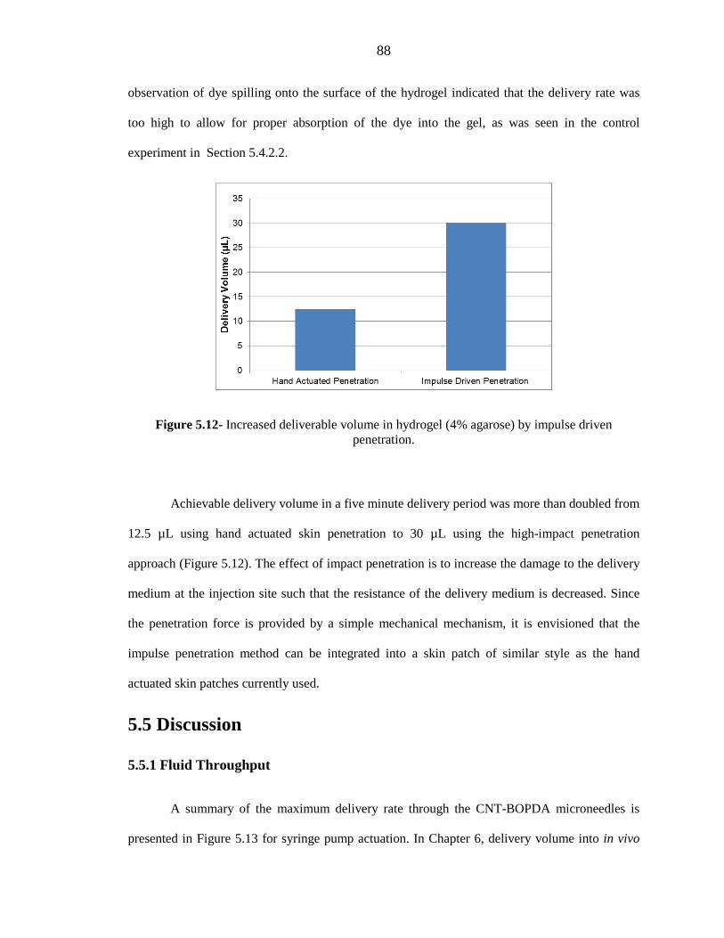
88
observation of dye spilling onto the surface of the hydrogel indicated that the delivery rate was
too high to allow for proper absorption of the dye into the gel, as was seen in the control
experiment in Section 5.4.2.2.
Figure 5.12- Increased deliverable volume in hydrogel (4% agarose) by impulse driven penetration.
Achievable delivery volume in a five minute delivery period was more than doubled from
12.5 µL using hand actuated skin penetration to 30 µL using the high-impact penetration
approach (Figure 5.12). The effect of impact penetration is to increase the damage to the delivery
medium at the injection site such that the resistance of the delivery medium is decreased. Since
the penetration force is provided by a simple mechanical mechanism, it is envisioned that the
impulse penetration method can be integrated into a skin patch of similar style as the hand
actuated skin patches currently used.
5.5 Discussion
5.5.1 Fluid Throughput
A summary of the maximum delivery rate through the CNT-BOPDA microneedles is
presented in Figure 5.13 for syringe pump actuation. In Chapter 6, delivery volume into in vivo

89
rabbit skin actuated by a syringe pump will be shown to have agreement with the data reported
here for volume delivered under hand actuation into in vitro swine skin. Delivery rate through in
vitro swine skin is similar in magnitude to hydrogel (4% agarose). Given the relative ease of
preparing hydrogel along with the ability to reuse microneedles for hydrogel delivery, hydrogel is
vetted as a good laboratory model for testing the fluid conduction of microneedle-skin patch
system performance before progressing to animal models. Delivery into the skin models (in vitro
swine skin and hydrogel [4% agarose]) has an order of magnitude lower delivery rate than
delivery into the air. In the context of the flow model presented previously, it is clear that the
main source of hydraulic resistance during delivery comes from the delivery medium rather than
the microneedles.
Figure 5.13- Delivery rates for a 3 x3 microneedle array in each delivery medium. Skin refers to both in vitro swine skin and in vivo rabbit skin. Hydrogel has a concentration of 4% agarose.
Previous work using hollow microneedles of the same height have shown similar or
lower delivery rates into the skin (Table 6.1). A full discussion of comparable microneedle
delivery systems is reserved until Section 6.4. Comparable delivery performance, as shown here,
combined with the fabrication advantages outlined in Chapter 3, demonstrates that the CNT-
polymer microneedle, regardless of specific delivery platform, is capable of being developed into
a successful microneedle technology.
0.1
1
10
100
1000
10000
Skin Hydrogel Hydrogel Into the Air
Deliv
ery
Rate
(µL/
min
)
(Impact Penetration)

90
The CNT-BOPDA microneedles and other contemporary microneedle designs in the
height range of 200 – 500 µm are typically limited to delivery volumes on the order of microliters
(Table 6.1). The current challenge in the field of hollow microneedles is to increase the total
delivery volume to the range of hundreds of microliters. By reaching this delivery threshold,
liquid drug formulations that are currently administered by hypodermic injection can be more
directly adapted to the hollow microneedle delivery architecture.
To further increase the delivery volume and rate of the CNT-BOPDA microneedles, a
number of improvements can be made to either the microneedle or delivery platform. Options for
modifying the delivery platform include replacing hand actuation with a micro or MEMS based
pump that can allow for higher applied pressure, resulting in higher flow rates at the cost of
increased price and complexity (Ma et al. 2006). Additionally, changing the mechanics of
microneedle penetration, as discussed in terms of impact penetration versus hand actuation, has
been shown here to reduce hydraulic resistance of the delivery medium to significantly increase
the delivery rate. Previous work has shown that a spring-actuated delivery device, similar to the
lancet used here, can be incorporated into an integrated delivery platform (Burton et al. 2011).
Other methods that have been used in contemporary designs include slightly retracting the
microneedles after skin penetration in order to create a low resistance cavity for injecting fluid
into the skin (Wang et al. 2006).
Increasing the length of the microneedles, as described in Chapter 2, would allow for
deeper penetration into the skin, leading to higher delivery rates as skin permeability increases in
deeper tissues (Schmook, Meingassner, and Billich 2001). In comparing the CNT-polymer
composite microneedles to other hollow microneedle designs, one major difference in terms of
delivery pathway can be observed. Whereas the lumen of the CNT-polymer composite
microneedle terminates on the top surface of the microneedle, most microneedle designs follow
the design of the hypodermic needle with the lumen terminating on the side of the needle (Figure
91
3.4h) (Häfeli et al. 2009). A previous study examined microneedle-skin interaction in a finite
element simulation to compare the release from a top-terminated lumen and a side-terminated
lumen. Results from the simulation showed that the high pressure exerted on the skin at the tip of
the microneedle restricts fluid delivery, whereas the relatively low pressure along the side of the
microneedle provides a better conduit for transporting fluid from the needle into the skin (Roxhed
et al. 2007). One option to include a side-terminated lumen to the CNT-polymer composite
microneedles would be to micromachine the top of the needle after curing the polymer resin.
Micromachining is used commonly in producing a sharpened tip for silicon and polymer
microneedles. However, micromachining provides coarse control in assuring uniformity over
large arrays of needles and limits scalability for large arrays (Baron et al. 2008).
An alternative approach, unique to CNT-polymer composite fabrication, can be used to
create a side-terminated lumen without limiting scalability for large arrays. The height of VA-
CNT arrays is very sensitive to a number of conditions during fabrication, including gas mixture
and temperature during CVD as well as the thickness and composition of the catalyst. By creating
a site specific defect in the catalyst, a side lumen can naturally be created by the stunted height of
the VA-CNT array above the defective catalyst. Figure 5.14 illustrates this concept on a CNT
scaffold. In this example, the defect was created by over-sonicating the sample during photoresist
lift-off, which damaged a small segment of the catalyst ring.
Defects can also be engineered during catalyst patterning by depositing catalyst in two
steps in order to use two photoresist masks to separately deposit a pristine catalyst and a defective
catalyst. A defective catalyst can be achieved by either changing the thickness of the iron catalyst
or by failing to deposit either the alumina or silicon dioxide buffer layers that support the iron
catalyst. It is expected that this design is easily supportable through microneedle fabrication, as it
has been shown that polymer resin conformally coats the CNT scaffold during processing, and no

92
changes are made to the intrinsic CNT structure that would affect the transport of polymer resin
through capillary action.
(a)
(b)
Figure 5.14- (a) Conceptual illustration of catalyst distribution on silicon wafer. (b) CNT scaffold with side-terminated lumen caused by the presence of site-specific defective catalyst.
5.5.2 Mechanics of Microneedle Penetration
A notable difference in the CNT-polymer microneedle compared to other designs is the
simplicity of the geometry. Absent in the CNT-polymer microneedle is the typical tapered

93
geometry seen in most contemporary hollow microneedles (Roxhed et al. 2007). A tapered
geometry is typically utilized to prevent buckling failure and fracture of the microneedle during
skin penetration (Davis et al. 2004). However, the CNT-polymer composite microneedle has
consistently demonstrated successful skin penetration without structural damage in the height
range of 200-300 µm. However, when considering increasing the microneedle height or
increasing the aspect ratio, a taper may need to be considered. General fabrication options for
fabricating tapered microneedle geometry are considered in Section 3.4. Additionally, a study on
utilizing oxygen plasma etching as a novel method to introduce a taper to CNT geometry is
delineated in Chapter 7. Buckling failure of the microneedles during skin penetration was
observed starting at a needle height of 500 µm for the CNT-BOPDA microneedles with standard
outer and lumen diameters (Figure 5.15).
Figure 5.15- 500 µm tall CNT-BOPDA microneedles damaged after in vitro skin penetration test.
In considering the tip of the microneedle, previous study of similar blunt tipped
microneedles has shown that the force required to penetrate the skin depends purely on the outer
diameter of the microneedle tip rather than the surface area of the tip. This is because on the
length scale of the diameter of the microneedle tip, the skin cannot locally deform into the lumen

94
as a mechanism to ease stress (Davis et al. 2004). This observation is important in showing that
the requirements of achieving skin penetration and conducting fluid through the microneedle can
be decoupled in the microneedle design, as the outer tip diameter determines the force required
for penetrating the skin, whereas the lumen diameter determines the hydraulic resistance of the
microneedle.
Many contemporary microneedle designs feature a very pronounced taper. This is
especially true for silicon microneedles, where the brittle nature of silicon makes the needle
particularly susceptible to fracture resulting in a complete break of the needle. In contrast, for the
CNT-polymer composite microneedle, buckling failure does not necessarily result in needle
breakage. As seen in Figure 5.15, 2 out of 9 microneedles are severely broken, with the top
section of the microneedles attached by the thinnest of margins. The rest of the microneedles
show deformation in shape but remain intact and attached to the polyimide base. This difference
in failure mode is important in assessing patient safety, as a needle material susceptible to fracture
and breakage is more likely to become lodged in the patient rather than a needle that deforms but
remains attached to its delivery platform.
A potential advantage to not having a taper in the CNT-polymer composite microneedle
is the ability to penetrate deeper into the skin for a given microneedle height. The increasing
diameter of a pronounced taper limits the overall penetration depth of a microneedle. In a
previous study, silicon microneedles with a pronounced taper and a total needle height of 200 µm
were shown to have a penetration depth limited between 60 µm and 70 µm (Häfeli et al. 2009). In
comparing the penetration depth to the geometry of the microneedle, it can be observed that the
penetration depth is coincident with the slender, cylindrical tip of the microneedle before the
diameter of the needle begins to increase with the taper. Thus in this instance, it is observed that
the taper is the limiting feature that inhibits further penetration of the microneedle. Without the
presence of a taper, or similar diameter broadening geometry, to limit penetration depth, the

95
CNT-polymer microneedle is predicted to have a greater penetration depth than contemporary
microneedles of similar lengths. A conservative estimate for penetration depth of the CNT-
polymer microneedle is 100 – 125 µm, or 30-65 µm greater penetration depth than the silicon
microneedle.
In relying on hand actuation to press the microneedles into the skin, the number of
microneedles that can be supported is limited. For the CNT-BOPDA microneedles, a compression
force in the range of 1.1 to 1.6 N per needle is applied to achieve skin penetration for a total force
of 9.9 to 14.4 N. Maximum sustainable finger force is limited to 35 N for a healthy adult (NASA
1995). Taking into account the goal of universal accessibility, an upper limit of penetration force
is estimated to be approximately 17 N (50% maximum finger force). In this case, hand forced
skin penetration limits the number of CNT-BOPDA microneedles on a single device to 10 – 15
microneedles. The limit on the number of needles ultimately limits the deliverable volume, as
each microneedle operates as an independent conduit for delivery into the skin. Thus, an external
applicator, similar to the lancet used here for impact penetration, may become necessary for
applications requiring large delivery volumes from a large array of microneedles.
5.6 Conclusions
The utility of the CNT-polymer composite microneedles has been shown through liquid
delivery experiments in hydrogel as well as in vitro liquid delivery in swine skin. Performance of
the CNT-polymer microneedles was demonstrated on a variety of delivery platforms, including
modified syringes, hand actuated skin patches, and pump actuated skin patches. The microneedles
were portable to a variety of drug delivery platforms due to the thin, flexible nature of the
polymer base. From the cumulative ensemble of delivery experiments, no failure of the polymer
base, such as cracking or tearing, was observed. This result demonstrates that the thin SU-8 and
polyimide bases are mechanically supportive of the microneedle array during delivery.

96
The design of the microneedles was sufficient for supporting delivery under the limited
forcing constraints of hand actuation for both skin penetration and fluid flow. The dual reservoir
skin patch, as tested with the CNT-BOPDA microneedles, was shown to provide a unique
architecture to avoid accidental discharge of drug by separating the action of microneedle
insertion into the skin and fluid actuation. In comparing delivery into the skin and delivery
through the microneedles without a delivery medium (into the air), it was found that the delivery
rate into the air is over three orders of magnitude higher than the delivery rate into the skin. From
this result, it can be concluded that the predominant source of hydraulic resistance during delivery
is not the size of the microneedle lumen but rather the hydraulic resistance of the skin. Future
strategies and work to reduce the hydraulic resistance presented by the skin will need to focus on
how the microneedle interacts with the skin upon insertion.
Deliverable volume into the skin is comparable to similar to contemporary microneedles
of the same length. Several approaches to separately improve the skin patch and the microneedle
were investigated with the goal of further improving the delivery volume and rate. For the skin
patch, replacing hand forcing with an external applicator to drive the microneedles into the
delivery medium was shown to increase total deliverable volume. For the microneedle, increasing
the length of the microneedle and moving the termination point of the lumen from the top surface
to the lateral surface are considered as future strategies for increasing delivery volumes.
Ultimately, by showing here that the microneedles can deliver drug into the skin
combined with the simplifications in fabrication as discussed in Chapter 3, the CNT-polymer
composite architecture is vetted as a potential microneedle technology. The portability of the
CNT-polymer microneedle by a thin polymer base along with the flexibility in microneedle
geometry, facilitated by the bottom-up fabrication method, can facilitate the expansion of the
CNT–polymer architecture to a wide range of drug delivery platforms.

97
Chapter 6
In Vivo Delivery
6.1 Introduction
In Chapter 5, different configurations of microneedles and delivery systems were
investigated. Here, a single configuration of CNT-BOPDA composite microneedles attached to a
hand actuated dual reservoir skin patch is used as a case study for fentanyl delivery in New
Zealand White Rabbits. In contrast to the previous chapter that focused on the physical aspect of
delivery of both the microneedles and the skin patch, the focus here is on the microneedle-skin
patch system as a whole and its ability to deliver drugs systemically.
The objectives of this study are to:
• Determine the onset of action for microneedle delivery of fentanyl (time between
application and systemic detection).
• Assess deliverable drug volume as compared to in vitro experiments.
• Determine if the microneedle injection is qualitatively painless.
• Assess the ability to successfully administer microneedle trandermal patch to a live
animal model and assess damage to the microneedles, if any, after delivery.
The scope of the in vivo delivery experiment is not a comprehensive pharmacokinetic study, but
rather to collect baseline information on the delivery rate of microneedles compared to standard

98
drug application routes such as topical and hypodermic injection, and assess the ease in which a
hand actuated microneedle patch can be applied to a live subject.
Fentanyl is a highly potent opioid analgesic, with a potency 50 to 100 times higher than
morphine (Mather 1983). Fentanyl can be administered by multiple methods, including
hypodermic injection and topical patches (Hess, Stiebler, and Herz 1972; Foley et al. 2001;
Mather 1983). Fentanyl is chosen for the in vivo study, as the high potency of fentanyl does not
require the delivery of large drug volumes, and can thus be successfully delivered despite the
delivery volume limitations of microneedles discussed in Chapter 5. Fentanyl is absorbed
systemically, allowing for the delivery to be characterized in time by taking blood samples
throughout the experiment to measure the concentration of fentanyl in the blood plasma. Fentanyl
is highly dissolvable in water up to a maximum concentration of 25 mg/mL, allowing for delivery
of an aqueous solution similar to prior laboratory and in vitro experiments. Furthermore, the
commercial availability of fentanyl topical patches and injectable aqueous solutions allow for
direct comparison of microneedle delivery with topical and subcutaneous hypodermic delivery.
The overall systemic delivery for the microneedles is expected to be a hybrid of
hypodermic injection and a topical skin patch. The microneedles have the same quick application
time as hypodermic injection, while incorporating the painless aspect of a topical skin patch.
Given the length of the microneedles, the microneedles are expected to pass through the stratum
corneum and deliver drug into the epidermis at a depth below the skin surface of 70-120 µm.
From the point of delivery, the drug diffuses into deeper tissues in the dermis and subcutaneous
layers. The high abundance of blood vessels in the deeper tissues provides the most direct route
for systemic drug absorption (Figure 6.1). Given that the hypodermic injection places drug
directly in the subcutaneous layer, it is expected that hypodermic injection will have the quickest
systemic onset of action compared to topical and microneedle delivery, which rely on diffusion to
reach deeper tissues and a sparser network of blood vessels in the upper layer of the dermis.

99
Figure 6.1- Illustration of the different layers of skin, the injection depth for each delivery method, and distance from injection point to blood vessels in the subcutaneous layer. (Adapted
from Health and Safety Executive, United Kingdom, 2014).
New Zealand White Rabbits are chosen as the animal model, as the size of the animal
allows for multiple blood samples to be collected over the course of the experiment. The delivery
of fentanyl citrate on rabbits has been well-characterized in previous studies and is commonly
used as a model for subsequent in vivo human delivery characterization (Hess, Stiebler, and Herz
1972; Foley et al. 2001). The fentanyl dose typically used for a 4 kg rabbit in veterinary
applications is similar to that for a human infant, making the data collected in this study relevant
for future investigations of using microneedles for in vivo delivery on humans. One drawback to
using rabbits is that the morphology of the skin is different from human skin due to the high
Topical Patch
Microneedles
Sub-Q Injection
Subcutaneous
Dermis(1-2 mm)
Epidermis(~100 µm)

100
concentration of hair follicles on the rabbit skin (Foley et al. 2001). Due to its mechanics and
composition, swine skin, as used in Chapter 5, is generally considered the best model for
assessing microneedle penetration. However, due to the high volume of previous work linking
fentanyl data delivery in rabbits to delivery in human patients, rabbits were deemed the most
suitable model for the in vivo study.
6.2 Materials & Methods
All experimental methods described within were approved by the California Institute of
Technology Institutional Animal Care and Use Committee (IACUC).
6.2.1 Microneedle Preparation
Dimensions of the CNT-BOPDA composite microneedle are consistent with what has
been described to present. Nine microneedles are patterned into a 3 x 3 microneedle array with 1
mm spacing between needles. The outer and luminal diameter of the microneedles were 100 and
30 µm respectively. Microneedles used in this experiment have a length in the range of 210 – 230
µm, with the standard deviation in height in a single array averaging 9 µm. A 15 nm thick layer
of platinum/palladium is sputter coated onto the microneedles to allow for imaging of the
microneedles before and after the in vivo experiment. Dual reservoir skin patches, as described in
Section 5.2.1.4, are used as the delivery platform.
Before mounting to skin patches, microneedles are imaged in SEM to verify the
microneedle dimensions, ensure uniformity between the needles, and to verify the absence of any
anomalous defects. After the in vivo experiment, microneedles are separated from the skin patch
with a razor blade and reimaged under SEM. Comparison of SEM images taken before and after
the delivery experiment are used to assess whether the microneedles sustained any damage during
the delivery.

101
After affixing microneedles using methods described previously, the skin patch is filled
with the aqueous fentanyl solution through the syringe adapter on the side of the skin patch. The
skin patch is tested by squeezing the primary drug reservoir to release a small amount of drug to
verify flow through all 9 microneedles on the skin patch. After testing the flow, the primary drug
reservoir is replenished, and the surface of the microneedles is wiped dry with a kimwipe. Finally,
the filled skin patches are weighed on an analytic balance with a precision 0.1 mg (AGCN100,
Torbal Scales, Clifton, NJ). Skin patches are weighed again after delivery to determine the
amount of drug that was delivered during the experiment, which allow the deliverable volume to
be measured with a precision of 0.1 µL.
6.2.2 Fentanyl Delivery
Six female New Zealand White Rabbits (Charles River, Wilmington MA) were assigned
randomly to three groups. Two rabbits were assigned to the microneedle experimental group, two
rabbits were assigned to the topical skin patch control group, and two rabbits were assigned to the
hypodermic injection control group. The delivery experiment was performed in 2 rounds. During
each round, each animal received a single dosage of fentanyl by the predetermined delivery
method. The animals had a rest period of 1 month between rounds to allow for the natural
elimination of any traces of fentanyl. Each rabbit was examined by a veterinarian to verify the
rabbit was in good health before proceeding with each delivery experiment. During the first round
of delivery experiments, the rabbits were 13 weeks old and had an average weight of 2.80 ± 0.13
kg. During the second round of delivery experiments, the rabbits were 18 weeks old and had an
average weight of 3.53 ± 0.20 kg.
Fentanyl was delivered on the dorsal side of the rabbit near the spine of the rabbit for
each delivery group. To prepare the delivery site, hair was removed in an approximate 8 cm x 8
cm area for all rabbits. The majority of hair is removed with hair clippers. The remaining hair is

102
removed by applying Nair Hair Removal topical solution for several minutes and then rinsing the
skin (Nair, Church & Dwight CO, Ewing, NJ). The Nair treatment was observed to produce a
mild inflammatory response in the skin that was unrelated to the fentanyl delivery.
For topical patch administration, a commercial fentanyl patch (Duragesic Fentanyl
Transdermal System, Janssen Pharmaceuticals, Titusville, NJ) of dosage 12 µg per hour is
applied to the shaved dorsal skin of the rabbit (Figure 6.2) for the duration of the experiment, 8
hours. As Figure 6.2 shows, a small residual amount of fur is still present on the rabbit after the
hair removal process. The fentanyl patch is specifically positioned to minimize contact with
residual fur, as the presence of fur under the patch can affect the delivery rate into the skin (Foley
et al. 2001).
Figure 6.2- Fentanyl patch on rabbit skin.
For hypodermic injection, a commercial aqueous fentanyl solution of concentration 50
µg/mL was used (Baxter Healthcare Corporation, Deerfield, IL). The target dosage for
hypodermic injection was 12.5 µg per kilogram body weight, which is far below the maximum
intravenous dosage for a rabbit (Foley et al. 2001). Prior to delivery, topical EMLA cream (2.5%
lidocaine, 2.5% prilocaine) was applied to the injection site in order to numb the area. To ensure

103
delivery into the subcutaneous layer of the skin, the dorsal skin was pinched together and then
injected with the hypodermic needle.
The microneedle skin patch is assembled as delineated in Section 6.2.1. Like the
hypodermic injection, a target dosage of 12.5 µg per kilogram body weight was used. A
concentrated aqueous fentanyl solution was prepared from fentanyl citrate salt (Sigma-Aldrich,
St. Louis, MO) for microneedle application. This method was used to prepare the microneedle
sample since the commercially available fentanyl solution designed for hypodermic injection
requires injection volumes on the order of 700- 950 µL, far beyond the delivery capability of the
microneedles as shown during in vitro skin delivery tests. For the first round of delivery
experiments, the fentanyl concentration was set to 3.6 µg/ µL for a target delivery volume of 10
µL. For the second round of delivery experiments, the fentanyl concentration was increased to
11.17 µg/ µL to allow for a smaller delivery volume of 4 µL.
For applying the microneedle patch to the skin, the patch is placed along the center of the
rabbit’s back to ensure good contact with the skin. Similar to placing the topical patch, the
microneedle patch is placed away from residual hair to avoid delivery occlusion. Using the dual
reservoir skin patch, the microneedles are first inserted into the skin using the force of a single
finger. After insertion, a second finger is used to actuate the primary drug reservoir to begin drug
flow. From previous in vitro experiments, it is expected that the delivery is completed within 5
minutes. To ensure maximum deliverable volume, the patch is held in place for 10 minutes. After
10 minutes, the primary drug reservoir is released while continuing to hold the microneedles
affixed to the skin. After an additional minute, the finger holding the microneedles in the skin is
released and the skin patch is removed from the rabbit. The surface of the skin is inspected
visually and wiped with a kimwipe to check for any residual drug not absorbed by the skin.

104
Blood collection was facilitated by an intravenous butterfly catheter placed in the
marginal ear vein of the rabbit before the experiment. Rabbits were placed in an Elizabethan
collar for the duration of the experiment to prevent the animal from disturbing the catheter. The
catheter was secured to the rabbit by wrapping the ear and catheter together in bandaging tape
(3M Vetrap Bandaging Tape, Saint Paul, MN). 3 mL of blood was collected from each rabbit at 6
time points: before fentanyl application and then 15 minutes, 30 minutes, 60 minutes, 2 hours,
and 8 hours after application. During blood collection and fentanyl administration, rabbits were
wrapped in a large towel and manually restrained. Blood samples were tested for the presence of
fentanyl through ELISA (enzyme-linked immunosorbent assay) analysis performed by an
external laboratory (AniLytics, Gaithersburg, MD). The ELISA analysis had a minimum
detection limit of 0.013 ng/mL.
6.2.3 Saline Syringe Pump Delivery
To verify the delivery volume obtained during the fentanyl trial, a follow-on study was
performed using the CNT-BOPDA microneedles with the syringe pump skin patch as described
in Section 5.2.1.5. Fentanyl was replaced with a 0.9% saline solution, such that the delivery
volume could be modified without concern for the medicinal effect on the rabbit (Abbott
Laboratories, Abbott Park, IL). A rabbit was chosen randomly from the 6 rabbits used during the
fentanyl trial. Before beginning the saline trial, the rabbit was given a minimum 1 month rest
period. Total delivery time was set for 5 minutes, and the saline was flowed at a continuous rate.
Successful delivery was determined by examining the skin after delivery to ensure that saline did
not pool on the skin surface and that the skin patch did not leak during delivery, which would
indicate a significant buildup of back pressure caused by the high hydraulic resistance of the skin.

105
6.3 Results
Each delivery mechanism was tested four times over the course of two rounds of fentanyl
delivery experiments. Figure 6.3 shows the onset of action for each delivery group. Onset of
action is defined as the time between fentanyl application and the time it is first measured in the
blood plasma. Dashed lines represent the scheduled blood sampling times delineated in Section
6.2.2. Deviation from the scheduled blood sampling times represents the actual blood sampling
time during the experiment. The onset action is defined as a range between blood sampling times
where the closed marker indicates the first positive measurement of fentanyl in blood plasma, and
the open marker indicates the previous negative measurement of fentanyl in plasma. The precise
onset of action is presumed to occur somewhere along the highlighted range.
Figure 6.3- Onset of action for fentanyl as determined by time between fentanyl application and first detection of fentanyl in plasma. Open circle represents last negative measurement of fentanyl
in plasma. Closed circle represents first positive measurement of fentanyl in plasma. Dashed black line represents scheduled blood sampling times.
Hypodermic injection has an almost instantaneous onset of action, with the first plasma
sample taken at 15 minutes showing a non-zero fentanyl application for all 4 delivery
106
experiments. The near instantaneous result is expected, as fentanyl is injected directly into the
subcutaneous layer and agrees with previous results (Hess, Stiebler, and Herz 1972). The topical
patch has an onset of action between 1-2 hours for three patches, and an onset of action between
30 minutes to an hour for 1 patch. For the experiment with the early onset of action, a more
pronounced inflammatory response was observed from the Nair pretreatment. Previous work has
shown that damage to the outer layers of skin caused by an overaggressive Nair treatment can
result in an increased transport rate through the skin (Foley et al. 2001). Therefore, the onset of
action is determined to be between the nominal 1 hour and 2 hour blood sampling times for the
topical patch group.
Four microneedle patches were tested during the in vivo experiments. For the first round
of experiments, the concentration of the fentanyl solution was targeted for a delivered drug
volume of 10 µL. Actual released drug volume was determined to be 4 µL. Due to the
underdosing of fentanyl and the sensitivity limits of the ELISA kit, no traces of fentanyl were
detected in the plasma for the first experiment cycle. In the second round of experiments, the
concentration of the fentanyl solution was increased to target a 4 µL dose, as discussed in Section
6.2.2. Of the two microneedle deliveries in the second round experiments, one microneedle
delivery failed due to bad skin contact with the rabbit during the experiment. During delivery, the
rabbit moved, causing the microneedles to lose contact with the skin. For the successful delivery
in the second round, the onset of action was found to be between 1-2 hours, the same range as the
topical patch.
A large time range is investigated, as the onset action for microneedles has not been well-
characterized in previous work. Furthermore, this investigation represents the first in vivo
experiments to deliver fentanyl through a microneedle. Now that the approximate onset of action
times are defined for each delivery mechanism, future experiments can focus in the 1 to 2 hour

107
range to determine conclusively whether microneedles or topical patches have a faster onset of
action.
The general agreement of onset action for microneedles and topical patch is expected, as
the diffusion length from the epidermis to the subcutaneous layer is on the order of millimeters,
and the difference in starting depth in the skin between the microneedles and topical patch is less
than 100 µm. The fentanyl plasma concentration of the skin patch and the microneedles is shown
at the observed onset of action (2 hours after application) in Figure 6.4. The fentanyl
concentration of the topical patch is 0.076 ± 0.005 ng/mL whereas the fentanyl concentration of
the microneedles is 0.063 ng/mL, which is 83% of the topical patch concentration. The measured
fentanyl concentrations were consistent with results seen in previous rabbit model studies on
topical fentanyl delivery (Foley et al. 2001).
Figure 6.4- Measured fentanyl concentration in blood plasma at onset of action.
An important consideration in comparing the topical patch to the microneedles is that the
commercial topical patch contains diffusion enhancers, which act to reduce the onset of action
compared to a standard aqueous fentanyl solution, which is used in the microneedle patch. The

108
molecular weight of fentanyl citrate, 0.528 kDa, is quite small compared to large molecule drugs
like insulin, with a molecular weight of 5.8 kDa. While small molecular drugs, like fentanyl, are
able to slowly diffuse through the skin in a manner of hours, large molecular drugs like insulin
are unable to cross through the stratum corneum layer of the skin, which is the outer layer of skin.
Therefore, large molecule drugs are dependent on a transdermal delivery system, like
microneedles or hypodermic injection, to overcome this boundary.
Thus, the primary objective of this experiment is not to show a more rapid onset of action
over a topical patch for fentanyl, but rather that the CNT microneedle-skin patch system
successfully delivers drugs into the epidermis and allows for diffusion into deeper tissues. For
small molecule drugs that can be delivered through topical patches, a distinct advantage
demonstrated is that while topical patches need to be worn over the course of hours to achieve
drug absorption into the skin, the microneedle skin patch only needs to be applied over the course
of 5-10 minutes to have the same effect. In essence, instead of having a drug reservoir on the
topical patch, the CNT microneedle-skin patch creates a small reservoir of drug in the epidermis,
allowing the external patch to be removed within minutes rather than hours.
Figure 6.5 shows a CNT microneedle array before (a,b) and after (c,d) in vivo delivery.
As before for in vitro swine skin delivery, no notable damage is seen on any of the microneedle
samples after in vivo rabbit skin delivery. Skin debris is readily identified on the polymer base as
well as along the side of the microneedle (c). The presence of large skin debris relative to the size
of the microneedle limits the use of the microneedles to a single-use device to avoid the risk of
possible occlusion of the microneedles.
In regard to pain associated with injection, rabbits did not tolerate hypodermic injection.
Rabbits held by manual restraint consistently flinched when contacted with the hypodermic
needle. This allowed the rabbit to break free of restraint and did not allow for the injection to be

109
administered. Rabbits needed to be given a pretreatment of EMLA cream, as described in Section
6.2.2, to numb the injection area in order for the injection to be administered successfully. The
dermal patch, as expected, did not produce any pain upon application. Due to the presence of the
Elizabethan collar on the rabbit during the experiment, it was unclear whether the patch was a
source of irritation to the rabbit, as the collar restricted the rabbit from scratching or biting the
patch. Rabbits readily accepted microneedle injection for the duration of the 10 minute
application. Rabbits were manually restrained during injection and did not physically respond to
the microneedles. This result is expected, as microneedles of similar and greater lengths have
been shown in previous studies to produce minimal or no pain sensation (Haq et al. 2009).
Figure 6.5- SEM Images of microneedles before (a,b) and after (c,d) delivery. Skin debris is present on the microneedles after delivery, but the microneedles do not sustain any structural
damage.
In order to assess possible skin irritation caused by the microneedles, the injection site
was imaged before delivery, immediately after delivery, and 8 hours after delivery. Figure 6.6
shows a microneedle injection site and the surrounding region 8 hours after delivery. Non-site-
(a) (c)
(b) (d)

110
specific irritation can be seen, as the skin is generally inflamed as a result of the Nair treatment,
similar to what was observed in Figure 6.2 for the rabbit undergoing fentanyl delivery through a
topical patch. At the specific microneedle injection site, no secondary irritation to the skin is
observed. For all microneedle treatments, no skin irritation was present 8 hours after delivery.
Immediately following delivery, a vague imprint of the polyimide base could be seen in the rabbit
skin for a couple of cases, but this imprint quickly vanished within the course of an hour.
The combined lack of pain and skin irritation seen in this in vivo study is promising,
considering that the CNT-BOPDA polyimide composite microneedle represents a new material
that has never before been used for skin penetration. These results are significant in
demonstrating that the CNT-polymer composite can be considered a viable microneedle platform
not only in terms of physical dimensions and material strength but also in terms of compatibility
with transdermal delivery.
Figure 6.6- Rabbit skin, 8 hours after microneedle application (circled region). No observation of microneedle specific skin irritation.
The deliverable volume of 4 µL observed in the fentanyl delivery trial using the dual
reservoir skin patch was verified using the same design of CNT-BOPDA microneedles on a

111
syringe pump skin patch. Constant flow rates of 500nL/min, 800nL/min, and 1 µL/min were
applied for 5 minutes, for total delivery volumes of 2.5 µL, 4 µL, and 5 µL respectively. Positive
delivery was observed for 2.5 µL and 4 µL. At 5 µL, a leak was observed in the syringe pump
skin patch, which is indicative of significant backpressure resisting the saline flow into the skin.
Thus, 4 µL over 5 minutes is viewed as a maximum volume for the microneedle-skin patch
system. While the rate of 800nL/min is presumably stable over longer time periods, it is
envisioned for practical applications that a manually actuated skin patch has a limit of 5 minutes
for a patient to continuously provide actuation force to the patch.
6.4 Discussion
Previous studies using hollow microneedles in the same length range (200-500 µm) as the
CNT-polymer microneedles have shown similar results to the CNT microneedle-skin patch
system in terms of onset of action and delivery rate. Gardeniers et al. reports preliminary data
using microneedles of length 350 µm to show the presence of diclofenac in the blood plasma only
after 6 hours of continuous delivery. The same study also repots the delivery of insulin through
the same microneedles at a steady delivery rate of 1U/hr (10µL/hr). For insulin delivery,
microneedles of height 350 µm took slightly under 2 hours to achieve a 20% reduction blood
glucose level, whereas microneedles of height 150 µm took approximately 2.5 hours (Gardeniers
et al. 2003). Davis et al. also examines insulin delivery comparing transdermal microneedles of
height 500 µm to topical delivery. In this study, the peak reduction of the blood glucose level for
the microneedle delivery occurs 4.5 hours after application, compared to 6 hours for topical
delivery (Davis et al. 2005). From these studies, it is observed that the onset of action for
systemic absorption from hollow microneedle delivery is consistently in the range of hours.
Therefore, in evaluating the future role of hollow microneedles, it is observed that
although the hollow microneedles physically resemble a hypodermic injection, the onset of action

112
for systemic absorption of the microneedles is more akin to an accelerated topical patch. This is
to be expected, as the short length of the microneedles is designed to bypass only the first few
layers of the skin, the stratum corneum, which provide the largest impedance for drug transfer,
especially for large molecule drugs (Figure 6.1) (Prausnitz, Mitragotri, and Langer 2004). In this
sense, hollow microneedles provide a head start past the more tortuous layers of the skin, but the
primary delivery mechanism of diffusion into deeper tissues remains unchanged.
Rapid onset of action (< 1 hour) from a microneedle delivery is most likely restricted to
applications where the target delivery site is in the skin at or near the injection site where long
range diffusion is not required. This has been demonstrated in a previous study examining the
delivery of lidocaine on coated microneedles to achieve local analgesia. Lidocaine, when applied
as a topical cream (such as EMLA cream as used here as a pretreatment before hypodermic
injection), has an onset of action ranging from 1-2 hours when used as a pretreatment for local
medical procedures in the skin. In contrast, lidocaine coated microneedles were able to achieve
the same analgesic effect with an onset of action of under a minute (Zhang et al. 2012) .
The current pairing of the CNT-polymer microneedle array with a hand actuated skin
patch generally results in low delivery rates into the skin. However, the results are comparable to
previous results using hand actuated skin patches and microneedles of similar height (Häfeli et al.
2009). 5 minutes is taken as the nominal application time for the CNT-polymer microneedle
consistent with the results from the in vitro study presented in Chapter 5. However, by hand
actuating the deformable drug reservoir with constant force, it is expected that the applied
pressure in the drug reservoir decreases as the reservoir begins to drain. Therefore, the delivery
rate is expected to decrease over the course of delivery. In this case, it is likely that the drug
delivery is complete before the total 5 minute application time, which would result in the CNT-
polymer microneedles having a delivery rate similar to what is reported in the Häfeli et al. study.

113
Reference Drug Number of Needles
Needle Height (µm)
Application Time
Total Drug Volume (µL)
Delivery Rate (µL/min)
Delivery Rate per needle (µL/min)
CNT/BOPDA Fentanyl 9 219 5 min (nominal) 4 0.8 0.089
Hafeli et al. Albumin 6 200 1 minute 3.2 3.20 0.53 Roxhed et al. Insulin 21 400 3 hours 6 0.03 0.0014 Gardeniers et al. Insulin 36 350 6 hours 60 0.17 0.0047
McAllister et al. Insulin 16 500 30 minutes 5 0.17 0.011
Table 6.1- In vivo microneedle delivery data for microneedles of length 200-500 µm.
Table 6.1 summarizes in vivo delivery data for hollow microneedles in the length range
of 200 µm to 500 µm. The results show that the delivery rate obtained in vivo for the CNT-
polymer microneedles is quite high compared to similar microneedles. Improvements in delivery
rate for the CNT microneedle-skin patch system can continue to be made using some of the
strategies outlined in Section 5.5, including the use of an external applicator and incorporating a
side-terminated lumen in the microneedle design. Even with these improvements, the global data
on drug delivery for hollow microneedles under 500 µm demonstrates consistently that the
platform is best suited for delivery of highly-concentrated drugs with minimal volume.
6.5 Conclusions
In vivo drug delivery of the CNT-BOPDA composite microneedle and dual reservoir skin
patch was investigated in delivering fentanyl transdermally to New Zealand White Rabbits. The
onset of action time of the microneedles was found to be of the same approximate time as
commercial topical fentanyl patches. At the onset of action, microneedles and skin patch
delivered a similar systemic dose of fentanyl, with blood plasma concentrations of 0.063 ng/mL

114
and 0.076 ng/mL respectively. Inspection of the microneedles before and after delivery
demonstrated that the microneedles did not sustain any damage during delivery. Inspection of the
injection site on the rabbit up to 8 hours after injection did not indicate any signs of skin irritation
that can be directly correlated to the microneedle delivery.
In assessing discomfort during delivery, rabbits tolerated the microneedle injection with
no observable signs of pain and discomfort. In contrast, rabbits unanimously did not tolerate a
direct hypodermic injection of fentanyl without pretreating the injection site with a local topical
analgesic. This indicates that the CNT-polymer microneedle achieves a painless delivery, which
is consistent with contemporary hollow microneedle architectures. The delivered drug volume
into the skin utilizing the hand actuated dual reservoir skin patch was 4 µL. The deliverable
volume was verified in follow-on experiments injecting saline using the syringe pump skin patch
variant of the dual reservoir patch. The CNT-BOPDA microneedle and dual reservoir skin patch
achieves high delivery rates compared to contemporary microneedle designs of the same needle
length.
This investigation has demonstrated the ability of the combined CNT-polymer
microneedle and hand actuated skin patch system to function as a transdermal drug delivery
platform. While microneedles and topical patches were shown to have similar onset of action for
fentanyl, the application of this result is restricted to small molecule drugs. Delivery of large
molecule drugs through topical patches is impossible due the restrictive permeability of the
stratum corneum. Therefore, microneedles are projected to have a well-defined role in providing
for painless, self-administered transdermal delivery of large molecule drugs, therapeutics, and
vaccines including insulin, proteins, DNA, and inactive viruses (Kim, Park, and Prausnitz 2012;
Sullivan et al. 2010). By bypassing the stratum corneum, microneedles allow for delivery of large
molecule drugs and therapeutics directly into the epidermis at which point they are able to diffuse

115
into deeper tissues in the same manner as small molecule drugs, as has been demonstrated here
with fentanyl.
Unlike small molecule drugs that can be effectively administered into the body by nearly
any delivery means, large molecule drugs can only be delivered via intravenous, intramuscular, or
subcutaneous injection. All of these methods for delivering large molecule drugs involve
significant discomfort and pain for the patient. Because of the limited therapeutic capabilities of
small molecule drugs, highly potent modern drugs typically consist of large molecules, such as
nucleic acids and proteins. Therefore, there is significant value in developing hollow microneedle
drug delivery platforms to enable effective and painless administration of large molecule drugs
that cannot be delivered via existing topical patches.

116
Chapter 7
Oxygen Etching
7.1 Introduction
The CNT-polymer microneedles, as has been demonstrated, are capable of acting as a
transdermal delivery system in their present configuration. Several options have been presented to
increase the performance or flexibility of the platform by allowing for features such as taller
microneedles, smaller tip diameters, and side-terminated lumens. In a departure from the
preceding chapters that examined the microneedle-skin patch system as a whole, here, a more
fundamental look is taken at how these goals can be achieved by introducing a new technique to
modify the CNT scaffold before polymer incorporation.
Capillography was introduced in Chapter 3 as a natural byproduct of thermal curing of a
polymer resin, causing the CNT scaffold to contract as volatile components of the resin
evaporated. Capillography is dependent on the evaporation of the wicking fluid to bring
neighboring CNTs into closer contact. Oxygen etching is introduced here as a more versatile
option for increasing the packing density and interaction between CNTs to induce macroscopic
shape change in CNT scaffolds.
CNT scaffolds are fabricated by standard catalyst patterning and chemical vapor
deposition techniques. After fabrication, CNTs are exposed to a low power isotropic oxygen
plasma. Oxygen plasma has two effects on CNTs: an increase in oxygenated functional groups
and an increase in the structural defects. The result of both modifications cause neighboring

117
CNTs to come into closer contact with each other, causing a macroscopic densification of the
CNT scaffold (Aria 2013). This technique allows for higher densification of CNT scaffolds than
is possible with capillography, and also makes the densification process controllable as well as
independent of a fluid medium. Here, oxygen etching is investigated within the scope of
exploring the concept of controllable shape change of macroscopic CNT structures for the
express application of hollow microneedles.
7.2 Materials & Methods
Two patterns of CNT bundles are fabricated in the same manner as described in Chapter
2. The first pattern investigated consists of hollow cylindrical pillars of similar dimension to the
CNT scaffolds used thus far. Pillars have a circular cross-section, with 150 µm and 120 µm outer
and lumen diameter respectively. The second pattern consists of a hollow pillar with a non-
axisymmetric cross-section to investigate the effect of oxygen etching on complex cross-section
geometries. Details on the geometry of the second pattern will be presented in Section 7.4. All of
the samples used in this study have a height in the range of 150 to 500 µm.
To achieve the oxygen etching effect, CNT pillar samples are placed in a plasma etcher
(M4L RF Gas Plasma System, PVA Tepla, Corona, CA). Plasma is produced remotely such that
the plasma is isotropic in distribution when it contacts the CNT samples. This allows for the CNT
pillar to be uniformly etched on all surfaces, rather than an anisotropic etching as typically seen in
other plasma processes such as reactive ion etching (RIE). The RF power is set for 50W, with an
oxygen flow rate of 150 sccm, and a chamber pressure of 500 mTorr. Process time is varied from
3 to 20 minutes.
As has been demonstrated in a previous study, the progression of oxygen etching on
CNTs can be quantified by measuring the atomic composition of the material and calculating the
oxygen to carbon ratio of the sample (Aria 2013). The atomic composition of the CNT scaffold is

118
measured through energy dispersive x-ray spectroscopy (EDS) (X-Max Silicon Drift Detector
EDS System, Oxford Instruments, Abingdon, England). EDS measurement is integrated with
SEM imaging to allow for EDS analysis on specific microneedles. In this way, the geometry and
the atomic composition of a CNT pillar are measured concurrently.
7.3 Experimental Results
7.3.1 Hollow Cylindrical Pillars
Oxygen etching effectively introduces a taper geometry to hollow cylindrical CNT
pillars. The base diameter of the pillar remains constant at 150 µm, while the tip diameter
progressively shrinks. Figure 7.1 demonstrates the geometry that can be achieved through oxygen
etching by starting with a hollow circular cylinder produced by standard catalyst patterning and
CVD methods. At low oxygen plasma dosages with a measured oxygen-to-carbon ratio below
10%, the tapering effect is uniform over the height of the pillar. Above this threshold, the etching
rate at the tip of the pillar decreases relative to the etching rate of the rest of the needle, causing
the formation of a neck just below the microneedle tip where the outer diameter reaches a
minimum value. Additionally, at high dosage levels, the base of the microneedles begins to
collapse. In the final configuration of the etched pillar as seen in Figure 7.1e, formerly vertical
CNTs now run horizontal across the substrate before coming together to support a pillar with a
reduced base diameter of 20 µm.
Figure 7.2 plots the progression of the pillar’s minimum diameter over the course of
etching. From the plot, it is observed that the etching behavior can be divided into three regions.
In Region I, the oxygen-to-carbon ratio, or O/C ratio, varies from 0% to 3.8%. The shape of the
pillar remains unchanged during this regime as the effects of etching can only be seen on the
atomic scale, as oxygenated functional groups, including carbonyl, carboxyl and epoxide groups,

119
begin to deposit on individual CNTs (Figure 7.1a) (Aria 2013). In Region II, a smooth taper is
developed along the length of the pillar. (Figure 7.1 b,c). Region II is characterized by an O/C
Figure 7.1- SEM images of microneedles at different stages of oxygen etching process with oxygen-carbon ratios of (a) 0% (Region I), (b) 8.49% (Region II), (c) 8.71% (Region II) (d)
18.05% (Region III) (e) 31% (Region III). All base diameters are 150 µm.
(a) (b)
(c) (d)
(e)
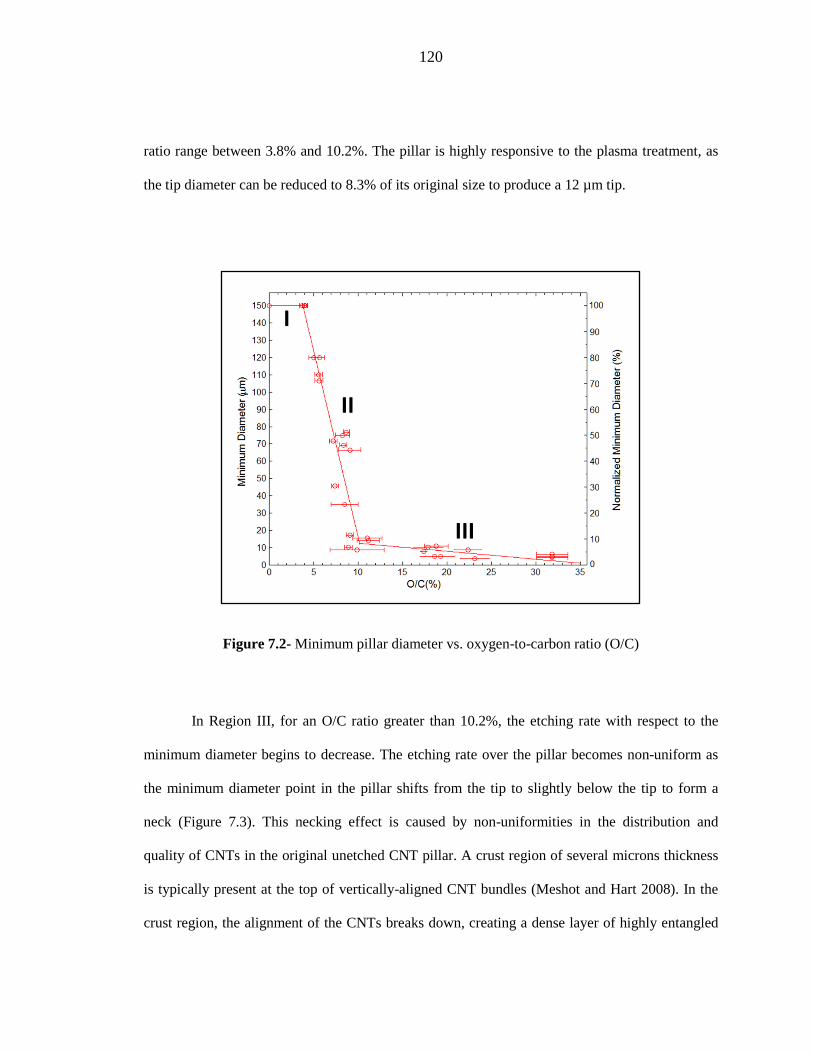
120
ratio range between 3.8% and 10.2%. The pillar is highly responsive to the plasma treatment, as
the tip diameter can be reduced to 8.3% of its original size to produce a 12 µm tip.
Figure 7.2- Minimum pillar diameter vs. oxygen-to-carbon ratio (O/C)
In Region III, for an O/C ratio greater than 10.2%, the etching rate with respect to the
minimum diameter begins to decrease. The etching rate over the pillar becomes non-uniform as
the minimum diameter point in the pillar shifts from the tip to slightly below the tip to form a
neck (Figure 7.3). This necking effect is caused by non-uniformities in the distribution and
quality of CNTs in the original unetched CNT pillar. A crust region of several microns thickness
is typically present at the top of vertically-aligned CNT bundles (Meshot and Hart 2008). In the
crust region, the alignment of the CNTs breaks down, creating a dense layer of highly entangled
II
I
III

121
CNTs. A conformal layer of amorphous carbon can also be observed in the crust region,
depending on the quality of the CNT growth. The increased nanotube density combined with the
presence of amorphous carbon makes the crust layer more resistant to etching than the rest of the
CNT pillar at high etching doses. Thus, as can be observed in Figure 7.3, the crust layer reaches a
minimum feature size while the rest of the pillar continues to contract. The neck of the pillar,
therefore, represents the boundary between the crust and well-aligned CNT layers.
Figure 7.3- CNT pillars with tip-neck ratios of (a) 1, (b) 2.36, (c) 3.3.
The observed necking effect occurs consistently in Region III for pillars where the tip
diameter drops below 10 µm (Figure 7.4). For the application of hollow microneedles, the
formation of a neck represents a failure mode for the CNT scaffold. The neck represents a weak
point in the structure that would be prone to failure during skin penetration. Above the 10 µm
diameter threshold, oxygen etching can be used to reproducibly fabricate microneedle geometry
to introduce a taper and produce a maximum reduction in tip diameter of 93%.
As the diameter of the pillar contracts, the thickness of the pillar also contracts (Figure
7.5). In examining the network of vertically-aligned nanotubes, the cumulative effect of oxygen
etching increases the interaction between neighboring CNTs pulling the nanotubes together.
(Figure 7.6) Previous results have linked this effect to the presence of oxygenated functional
group facilitating nanotube interactions, as well as an increase in electrostatic interactions during
(b)(a) (c)
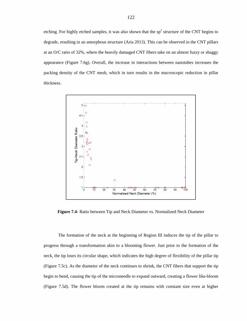
122
etching. For highly etched samples, it was also shown that the sp2 structure of the CNT begins to
degrade, resulting in an amorphous structure (Aria 2013). This can be observed in the CNT pillars
at an O/C ratio of 32%, where the heavily damaged CNT fibers take on an almost fuzzy or shaggy
appearance (Figure 7.6g). Overall, the increase in interactions between nanotubes increases the
packing density of the CNT mesh, which in turn results in the macroscopic reduction in pillar
thickness.
Figure 7.4- Ratio between Tip and Neck Diameter vs. Normalized Neck Diameter
The formation of the neck at the beginning of Region III induces the tip of the pillar to
progress through a transformation akin to a blooming flower. Just prior to the formation of the
neck, the tip loses its circular shape, which indicates the high degree of flexibility of the pillar tip
(Figure 7.5c). As the diameter of the neck continues to shrink, the CNT fibers that support the tip
begin to bend, causing the tip of the microneedle to expand outward, creating a flower like-bloom
(Figure 7.5d). The flower bloom created at the tip remains with constant size even at higher

123
etching rates. However as etching continues, the difference in the texture of the nanotubes is
observed as the CNTs become more rough and the pattern of vertically-aligned fibers becomes
heavily distorted, indicating an amorphous state of the CNTs.
Figure 7.5- Needle tips for oxygen-carbon ratios of (a) 0% (Region I), (b) 8.49% (Region II), (c) 8.71% (Region II) (d) 18.05% (Region III) (e) 31% (Region III).
(a) (b)
(c)
(e)
(d)

124
Figure 7.6- Densification of the CNT mesh for oxygen-carbon ratios of (a), (b) 0% (Region I), (c), (d) 8.49% (Region II), (e),(f) 8.71% (Region II) (g) 31% (Region III).
The reduction in thickness follows the same three regions that were used to describe
reduction in minimum diameter (Figure 7.6a). The reduction of thickness is also qualitatively
similar in each region to what was observed with minimum diameter. Thickness is initially
constant in Region I. In Region II, the CNT network is very responsive to etching as the packing
density of the network increases. In Region III, the thickness continues to decrease slightly but is
(b)
(d)
(a)
(c)
(e) (f)
(g)

125
less responsive to etching as in Region II. Instead, the primary characteristic of Region III is that
the CNTs become amorphous.
Figure 7.7- (a) Thickness vs O/C Ratio. (b) Normalized Thickness vs Normalized Tip Diameter.
(a)
(b)
I
II
III
I
II
III

126
Table 7.1- Transition point in terms of O/C ratio, as determined by linear fit to data.
In comparing the region transition points for diameter and thickness as defined by the
linear fit to the data, it is observed that for both the transition from Region I to II and the
transition from Region II to Region III, the transition occurs in thickness before diameter (Table
7.1). This indicates that contraction in diameter follows contraction in thickness. In Figure 7.7b,
the normalized tip diameter is plotted against the normalized thickness. It is estimated that the
diameter remains constant until the thickness reaches 82% of its original value, or 12.3 µm. A
single linear fit can be used to fit the data from Region II and Region III. This demonstrates that
despite large changes in etching sensitivity between Region II and Region III, the relative etching
rate between diameter and thickness remains the same throughout Regions II and III.
Oxygen etching, as presented here, represents a novel bottom-up approach to modify the
shape of CNT pillars. The isotropic distribution of the plasma allows for the etching effects to be
distributed throughout the pillar, rather than focused on the top surface as seen with anisotropic
etching processes such as RIE. Because of this isotropic distribution coupled with the low RF
power utilized, shape change is introduced not by destructive etching of CNTs, but rather by an
increase in interactions between neighboring CNTs, resulting in a more compact CNT network
that triggers shape change in terms of pillar thickness and ultimately pillar diameter on the
macroscopic scale.
Transition Thickness Diameter
Region I and II 3.23 % 3.82% Region II and III 9.57% 10.20%

127
7.3.2 Application to Complex Geometry
To demonstrate the potential of this technique to induce macroscopic shape change by
CNT densification, oxygen etching was applied to a shape with a complex cross-section. A
vertically-aligned CNT array is patterned into a flower-shaped ring with 5 petals connected to
each other by thin bridge elements (Figure 7.8a). Fabrication of the flower ring followed standard
catalyst patterning and chemical vapor deposition procedures. The circular cavity has a diameter
of 100 µm, and the distance from the center of the pattern to the tip of each petal is 100 µm. The
bridge element has a minimum thickness of 25 µm, and the petal has an approximate diameter of
40 µm. The shape is chosen to be qualitatively similar in design to a previous study that
investigated using capillography to induce shape change in complex patterns (De Volder et al.
2010).
Figure 7.8- (a) Flower ring patterned vertically-aligned carbon nanotubes after CVD. (b), (c) After oxygen etching, petals converge in the center to create a central pillar. Etching progression increases from left to right across the sample.
(a)
(b) (c)

128
Figure 7.8 b,c shows the result of oxygen etching in the flower ring geometry. The
thinner bridge elements are more easily penetrated by the oxygen plasma, allowing the bridge
element to compress at a faster rate than the petal element. The compression of the bridge before
the petal results in the petals being brought together in the center of the geometry to form a single
pillar from the intertwining petals. Figure 7.8b shows the progression of oxygen etching, moving
from left to right across the sample. The original 100 µm central cavity is reduced to a central
pillar with an ultimate tip diameter of 20 µm. Similar to the hollow cylindrical pillars investigated
earlier, the original catalyst patterned geometry remains present at the base of the flower ring
pillar. In Figure 7.8c, the CNTs that comprise the bridge element can be clearly observed near the
substrate. Higher up on the geometry, as the central pillar begins to form, the bridge element can
no longer be observed as the petal elements come into direct contact.
7.3.3 Comparison to Capillogrpahy
For the flower ring geometry, the same qualitative shape transformation achieved by
oxygen etching is also observed using capillography as the CNT densification method (De Volder
et al. 2010). However, oxygen etching, when compared to capillography, represents a much more
powerful platform for inducing shape change in CNT structures. Previous work using solvent
capillography on 200 µm diameter hollow cylindrical pillars, of similar thickness to the
cylindrical pillars investigated here, was able to demonstrate an ultimate tip diameter reduction of
44% (De Volder et al. 2010). In contrast, oxygen etching, as presented here, was able to reduce
the tip diameter of a cylindrical pillar by 92% by the end of Region II, before the occurrence of
necking in Region III.
Additionally, oxygen etching offers more process control as factors such as pressure,
flow rate, and RF power can be adjusted to optimize the etching process. In contrast, the
capillography process is fully dependent on the capillary transport and evaporation of a volatile

129
fluid medium. In order to affect change into the densification process of capillography, the fluid
medium must be changed, which only allows for large discrete changes in the process. Instead,
tuning of the plasma parameters in oxygen etching allows for fine control of the process.
7.4 Geometric Model
7.4.1 Motivation
Here, a geometric model for oxygen etched hollow cylindrical pillars is investigated. The
model uses pillars of the same dimensions as those used in Section 7.3.1. The ability of oxygen
etching to introduce a taper into cylindrical pillars, as demonstrated in the experimental results,
represents a major advantage in terms of the fabrication and delivery of CNT-polymer composite
microneedles as described in Chapter 3 and Chapter 5 respectively. The ability to controllably
fabricate a taper can improve microneedle delivery by reducing penetration force. This in turn
enables fabrication of microneedles with higher aspect ratios allowing for either longer
microneedles to achieve higher penetration depth or smaller diameter microneedles to increase
the microneedle packing density on a drug delivery platform.
Region II represents the ideal etching range for the application of microneedles, as
described previously, as the tip diameter can be reduced to 92% of its original size without the
complication of neck formation as observed in Region III. The geometric model presented here
aims to understand what occurs during Region II on the macroscopic scale in terms of structure
geometry. The ultimate goal of the model is to develop a tool for predicting the shape of tapered
microneedles fabricated through oxygen etching. In this way, the model allows for the design of a
specific microneedle geometry before committing to fabrication.
CNT bundles are approximated as an array of vertically-aligned strings with constant
properties throughout the length of the pillar. As a string, the CNTs can be deformed into any

130
curved geometry and maintain a constant length throughout the etching process. From this
approximation, the model aims to predict the profile of the needle geometry for a given etching
progression and examine secondary effects of etching that cannot be easily resolved through
experimental observation. It is expected that the height of the microneedles decreases during
etching as a result of the introduction of curvature into the needle shape. However, due to the
large variance in height of the CNT microneedles, this has not been conclusively proven from
experimental data.
7.4.2 Methods
The profile of the pillar is modeled as a hyperbolic cosine with the variable definitions in
terms of the microneedle geometry given in Figure 7.9 (Equation 7-1). A hyperbolic cosine is
typically used in models to represent the curvature of strings. Most commonly, a subset of
hyperbolic cosine curves, a catenary curve, is used to model the deformation of a string under its
own weight (Ng and Grimsdale 1996).
𝑦 = 𝑎 cosh �𝑥𝑏�
The origin of the coordinate system is placed at the center of the pillar tip. The direction along the
length of the microneedle is given by x. The radius of the pillar at a given height is given by y.
Equation 7-1 describes the profile for the right side of the microneedle. The microneedle is
axisymmetric such that the profile for the left side of the microneedle is given by reflecting the
profile generated by Equation 7-1 across the x-axis.
7-1
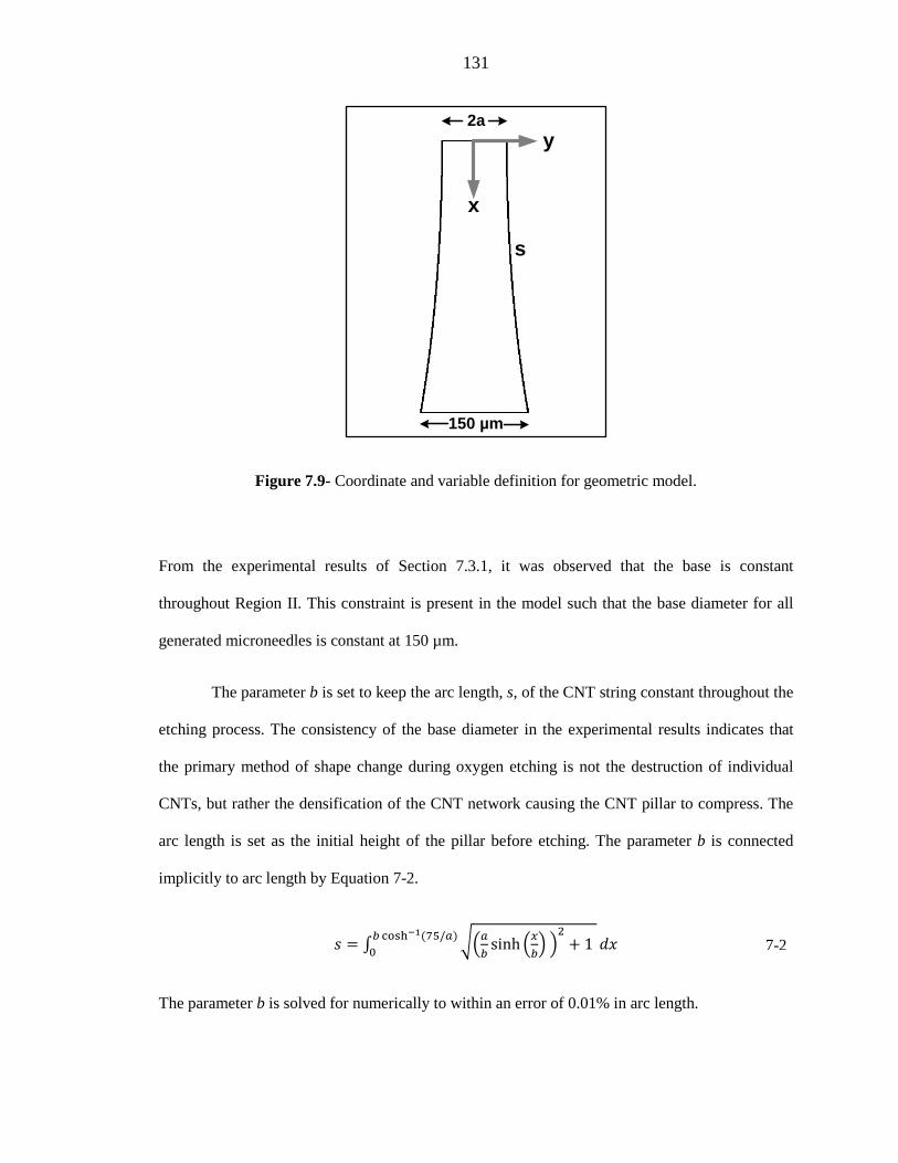
131
Figure 7.9- Coordinate and variable definition for geometric model.
From the experimental results of Section 7.3.1, it was observed that the base is constant
throughout Region II. This constraint is present in the model such that the base diameter for all
generated microneedles is constant at 150 µm.
The parameter b is set to keep the arc length, s, of the CNT string constant throughout the
etching process. The consistency of the base diameter in the experimental results indicates that
the primary method of shape change during oxygen etching is not the destruction of individual
CNTs, but rather the densification of the CNT network causing the CNT pillar to compress. The
arc length is set as the initial height of the pillar before etching. The parameter b is connected
implicitly to arc length by Equation 7-2.
𝑠 = ∫ ��𝑎𝑏
sinh �𝑥𝑏� �
2+ 1 𝑏 cosh−1(75/𝑎)
0 𝑑𝑥
The parameter b is solved for numerically to within an error of 0.01% in arc length.
x
y
s
2a
150 µm
7-2

132
7.4.3 Results
Figure 7.10 depicts the results of the model for the evolution of the profile of the
cylindrical pillar examined in Section 7.3.1 through Region II. A cylindrical pillar of initial
height 200 µm and 400 µm with a base diameter of 150 µm is depicted by the black cross section
(Figure 7.10 a,b respectively). As the O/C ratio of the pillar increases, as denoted in the transition
from blue to red profile, the tip diameter begins to contract. The side profile of the pillar is
initially linear and then becomes more concave as etching progresses. The termination of Region
II is depicted in the final pillar profile with a tip diameter of 10 µm.
Figure 7.10- Profile evolution of microneedle of 150 µm diameter base and (a) 200 µm height (b) 400 µm height. Images to relative scale.
The profile predicted by the model has very good agreement with the experimental
results from Region II, as exemplified in Figure 7.11a. The success of the model in Region II
highlights the smoothness of the profile along the length of the pillar created by oxygen etching.

133
In Region III, the model no longer captures the profile of the needle, as the profile cannot be
represented as a single global curve. Features such as necking at the tip and the collapse of the
base seen at higher etching rates create local deviations in the shape of the pillar. These
deviations prevent the profile from being defined simply from the boundary conditions of the
pillar. Figure 7.11b illustrates an example of this for a pillar with a slight neck at the boundary
between Region II and III. Comparing the pillar shape to the predicted curve, the model captures
the overall profile of the pillar with the exception of the top 20% of the pillar. The formation of
the neck changes the curvature of needle near the tip. In approaching the tip, the model predicts a
more gradual compression of the pillar diameter. However, the presence of the neck causes a
more rapid compression of the pillar, which is confined to the top 20% of the pillar.
Figure 7.11- Comparison of microneedle with model predicted profile for (a) Region II microneedle and (b) microneedle at transition between Region II and III showing early stages of
necking.
In addition to predicting the profile of the pillar, the constraint of the model to preserve
the arc length of the CNTs allows for insight into how the height of the pillar changes during
etching. This is of particular importance for the microneedle application, where the total height of
the microneedle determines the penetration depth of the microneedle in the skin. Figure 7.12
(a) (b)

134
shows the relation between normalized pillar height and tip diameter for initial pillar heights of
200, 300, 400, and 500 µm. The overall change in height during etching depends greatly on the
initial height of the pillar. In the span of etching, where the tip diameter is decreased by up to
93% of its original size, pillars of initial height 200 µm and 500 µm have a change in height of
2% and 11% respectively. While the change in height of the CNT scaffold during etching can be
neglected for shorter microneedles, change in height for taller CNT scaffolds can be significant
and needs to be incorporated into the final microneedle design to ensure proper penetration depth
in the skin.
Figure 7.12- Change in pillar height during oxygen etching as a function of tip diameter.
The relation between the model parameters a and b is illustrated in Figure 7.13 for
different initial pillar heights. The qualitative trend is the same for pillars of different initial
heights throughout the etching process, as represented by the shrinking tip radius a. In the
hyperbolic cosine function, b acts as a scaling parameter that determines the degree of curvature
Tip Diameter (µm)
Initial Pillar Height
Nor
mal
ized
Pilla
r Hei
ght (
%)

135
in the profile. For very large b, the profile of the pillar is linear. As b decreases, the curvature of
the pillar increases.
Figure 7.13- Model parameter plot for b vs. a (tip radius).
7.5 Conclusions
Bottom-up assembly, as demonstrated in the application of the CNT-polymer composite
microneedles, represents a powerful fabrication technique. The direct access to the nano-scale of
bottom-up assembly allows for faster, more flexible, and more scalable fabrication of micro- and
nano- structures than what can be achieved by conventional top-down fabrication. For CNTs,
traditional bottom-up fabrication methods, such as catalyst patterning and chemical vapor
deposition, restrict CNTs to extruded geometries with constant cross-section. This restriction
ultimately limits the adaptation of CNTs for microneedles and other applications.
Initial Pillar Height
136
Oxygen etching, as introduced here, is a passive, scalable method for overcoming this
obstacle by enabling 3D geometry for CNT structures. Using a cylindrical pillar of the same
diameter as the CNT-polymer composite microneedles, oxygen etching was shown to introduce a
tapered geometry to the cylindrical pillar, reducing the tip diameter by 93%. Further etching
beyond this point is possible, resulting in a blossoming-type transformation of the pillar tip that
illustrates the potential of unique shape transformations that can be achieved by oxygen etching.
However, for the express application of microneedles, the creation of a minimum diameter neck
during the blossoming transformation makes the geometry ill-suited for use as a microneedle
scaffold.
A geometric model was introduced for the cylindrical pillar to illustrate the shape
transformation during the second phase of oxygen etching (Region II). The profile of the etched
pillar can be represented as a single, smooth curve derived from a hyperbolic cosine function.
From the model, it was observed that oxygen etching reduces the height of the cylindrical pillar.
The magnitude of the height reduction is dependent on the initial height of the pillar. Short pillars
are only marginally affected with a 2% maximum height reduction for an initially 200 µm tall
pillar. In contrast, taller pillars are susceptible to larger height reductions with an 11% maximum
reduction for an initial pillar height of 500 µm.
Oxygen etching in itself operates as a bottom-up method, inducing densification in the
mesh of vertically-aligned CNTs. This densification then triggers macroscopic shape change, as
observed in the cylindrical pillar by a reduction in pillar thickness followed by reduction in tip
diameter. In CNT scaffolds with more complex geometry, oxygen etching can be used to generate
unique shape transformation beyond the capabilities of standard top-down fabrication approaches.
Here, a flower pattern with a hollow cavity was used to demonstrate how the CNT mesh is
compressed at a faster rate in thinner features than thicker features to cause macroscopic shape
change, as the flower collapses into a central hollow pillar via oxygen etching.
137
Oxygen etching represents a significant step towards creating scalable fully three-
dimensional CNT structures. For microneedles, this technique has the immediate application for
introducing tapered geometry and increasing the aspect ratio of microneedles, allowing for more
compact microneedle arrays and taller microneedles. The interplay of features with different
thicknesses, as illustrated in the flower ring example, may allow for fabrication of a much wider
range of geometries that would be of interest in the future development of the CNT-polymer
composite microneedle concept. In one potential application, by patterning an off-center lumen to
create a microneedle geometry with variable thickness, oxygen etching may initiate a side-
terminated lumen, akin to a hypodermic needle, on the thin side of the needle, while keeping the
geometry of the thick side of the needle unchanged. In future work to incorporate oxygen etched
geometry into the CNT-polymer composite framework, attention must be placed on the effect of
CNT densification on the transport of polymer resin through the CNT scaffold.

138
Chapter 8
Conclusion
8.1 Summary
8.1.1 Impact of the Study
Carbon nanotubes represent a multi-functional material with a unique set of structural,
electrical, thermal, and fluidic properties that make them attractive for use in an extensive field of
micro- and nano- devices. However, their widespread use to date has been restricted to CNT
powders, random alignment of CNTs without attachment to a common substrate, due to a lack of
methodology to shape and transport nanotubes after their fabrication. Here, in the context of
hollow microneedles, new fabrication techniques were demonstrated to increase the utility of
patterned vertically-aligned carbon nanotubes. Hollow microneedles represent an ideal
technology for evaluating the efficacy of incorporating CNTs into a complex mechanical system.
Current hollow microneedle designs rely on top-down approaches due to their heritage as a
spinoff technology from microelectronics based microfabrication. However, the technical
difficulty of creating high aspect ratio features and efficiently defining the lumen in top-down
approaches has added considerable fabrication complexity that has suppressed further
development of the technology.
Developing a more streamlined fabrication process for hollow microneedles through a
CNT architecture can have a profound impact on drug delivery and healthcare in general.
Microneedle skin patch designs such as the dual reservoir skin patch with CNT-BODPA

139
polyimide microneedles allow for painless, self-administered drug delivery. Enabling patients to
self-administer drugs normally reserved for hypodermic injection decreases the overall demand
for medical personnel and facilities. This is especially important for many countries where access
to medical infrastructure is limited. The enhanced immunogenic response of the skin to
vaccination, compared to deeper tissues where vaccines are typically injected, not only makes
microneedle administered vaccines more effective in inoculating a patient but also reduces dose
size, allowing for increased worldwide supply of vaccines.
8.1.2 Microneedle Fabrication
The fabrication methods presented in this thesis are aimed to fill the engineering gap
between vertically-aligned carbon nanotubes, fabricated by catalyst patterning and chemical
vapor deposition techniques, to fully functional microneedles. The nanoporosity of CNT
structures was found to be key to creating CNT-polymer composites that conform to the shape of
the original patterned CNT structure. Through spin coating, polymer resins simultaneously create
a composite with CNTs and form a common polymer base to allow for the microneedles to be
transferred onto delivery platforms. Two fabrication approaches were demonstrated: a thermal
curing technique for thermoset polymers and CNT Masked Photolithography, which uses CNTs
as a photomask for selectively curing negative photoresists. These methods were demonstrated
for a few representative polymers: BOPDA-polyimide for thermal curing and SU8-2025 & HD-
4110 polyimide for selective UV curing. These fabrication approaches both focus on simple,
passive fabrication steps such that the fabrication can potentially be scaled up to commercial
production. In particular, the thermal curing technique relies solely on the fluid mechanics of the
polymer resin to ensure the lumen remains unobstructed.
In order to make the fabrication technique more universally accessible, a set of
requirements was developed to screen the compatibility of arbitrary thermoset polymers and

140
negative photoresists with the presented fabrication process. Transport of polymer resin through
the lumen and into the nanoporous network of CNTs was analyzed by the Washburn model of
capillary action. From this analysis, it was determined that the intrinsic material properties of a
polymer resin alone could determine the resin’s compatibility with the thermal curing process. A
characteristic wicking velocity in the Washburn model, defined as the ratio of surface tension to
viscosity, is used to qualitatively describe the ease in which the polymer is wicked through the
nanoporous matrix. Polymer resins with a wicking velocity greater than 1 cm/s were found to be
generally compatible with the thermal curing technique.
CNT-polymer microneedles were fabricated with needles heights in the range of 200 –
250 µm in order to penetrate into the epidermis layer of the skin. Microneedles were cylindrical
in shape, with typical outer diameter between 100-150 µm and typical lumen diameter between
25-50 µm. Despite the seemingly blunt tip of the microneedles, microneedles attached to hand
actuated silicone skin patches demonstrated positive in vitro delivery of aqueous dye in swine
skin and in vivo delivery of fentanyl in rabbits without sustaining any structural damage.
However, in order to fabricate taller microneedles to penetrate deeper into the skin, a taper
geometry is needed to both reduce the force needed for skin penetration and increase the
resistance of the needle to fracture failure.
Isotropic oxygen etching is introduced as a new fabrication method to introduce a taper to
CNT microneedle geometry. Standard CNT fabrication practices only allow for construction of
CNT structures with constant cross-section, since the geometry of the CNT structure is defined by
catalyst patterning on a planar substrate. Prior to incorporating polymer, oxygen etching acts to
densify the nanoporous network of nanotubes to induce macroscopic shape change in the CNT
structure. In the case of a thin-shelled hollow cylinder, the size of the cylinder tip shrinks
axisymmetrically, while the base of the cylinder remains fixed via attachment to the substrate to
create a tapered needle geometry. Oxygen etching allows for the tip diameter to be controllably
141
reduced by up to 93% of its original size. Beyond this point, non-uniformities in the CNT
structure cause the etching rate to accelerate just below the microneedle tip to create a neck with a
diameter smaller than the tip. The existence of the neck makes the geometry inapplicable to
microneedles, as the neck represents a weakened point in the structure.
A model to predict the geometry of oxygen etched pillars was developed. CNTs were
modeled as deformable strings of constant length. As the tip diameter of the pillar is reduced, the
CNTs begin to bend near the base of the pillar, causing the height of the microneedle to shrink by
a maximum of 11%. The model is envisioned to allow for mechanical analysis of potential
microneedle designs before committing to catalyst patterning and CNT fabrication. A CNT
structure patterned into a flower with a central cavity is used to demonstrate the full potential of
oxygen etching to create three-dimensional CNT geometry beyond the range of top-down
fabrication. The presence of thick petal structures connected by thin bridge elements results in an
accelerated etching rate on the thin bridge elements, causing the petals to spiral into the center of
the ring to form a common pillar. While these oxygen etched designs were not incorporated into
microneedles during this study, the microneedle fabrication methods presented in this study are
all applicable to CNT structures created through oxygen etching.
8.1.3 Microneedle Delivery
The unique thin, flexible polymer base of the CNT-polymer microneedles allows for easy
incorporation of the microneedles onto a number of drug delivery platforms. In particular, a dual
reservoir silicone skin patch was developed for use with the CNT-polymer microneedles. Silicone
is chosen such that the flexibility of the silicone complements the flexibility of the polymer base
allowing for better contact with the skin. The dual reservoir skin patch is designed for manual
operation. A single finger presses the microneedles into the skin, and a second finger actuates
drug flow from a drug reservoir positioned offset from the microneedles. Development of the
142
dual reservoir was performed in parallel with the development of the CNT-polymer microneedles.
Hand actuation is seen as an advantageous platform for microneedle delivery by eliminating
pumps and the need for electricity to operate the delivery platform. This allows the hand actuated
skin patch to be made more cost-effectively and allows for wider distribution.
Delivery experiments using the dual reservoir skin patch along with several variant
platforms revealed deliverable drug volumes into in vitro swine skin and hydrogel (4%) of 4 µL
and 12 µL respectively within a delivery window of 5 minutes. Upon comparing the delivery
volumes with contemporary microneedles of similar lumen size and height, the CNT-polymer
microneedles were found to have a delivery rate consistent, with if not higher than, comparable
microneedle designs. Delivery results revealed that the primary source of hydraulic resistance for
the delivery system is not the microneedles, but rather the delivery medium.
To demonstrate the utility of the CNT-microneedles in the context of drug delivery, an in
vivo delivery study of fentanyl was performed in New Zealand White Rabbits. CNT-polymer
microneedle delivery was found to be qualitatively painless compared to hypodermic injection,
which was not tolerated by the rabbits. Microneedles were found to have the same approximate
onset of action in the range of 1-2 hours as a topical patch. Onset of action was determined by
first detection of fentanyl in the blood plasma. Performance of the CNT-polymer microneedle
was found to be comparable to other microneedles of the same height. Comparison to similar
microneedles confirmed an expected systemic onset of action in the range of hours. Deliverable
volume was found to be consistent with what was reported for the CNT-BOPDA microneedles in
the in vitro delivery study.
The combined results of the physical delivery study and the fentanyl study demonstrate
that the delivery performance of the CNT-polymer microneedle is akin to other microneedle
architectures of similar height. The results reveal that microneedles penetrating near the boundary

143
of the epidermis and dermis act as a hybrid between a topical patch and hypodermic needle. The
microneedles are shaped like hypodermic needles and have the same short application time.
However, the pharmacokinetics of drug absorption is more akin to the skin patch, as diffusion
remains the primary transport mechanism for the drug to reach capillary networks in the upper
dermis or denser blood vessel networks in deeper tissue layers.
8.2 Future Work
Given the fabrication advantages of the CNT-microneedles coupled with successful in
vitro and in vivo delivery studies demonstrating the CNT-microneedle as having the same
delivery performance of concurrent microneedle designs, this study has demonstrated that the
CNT-polymer composite microneedle concept is viable for further technological development.
The body of work presented here, representing a combination of fabrication methods and analysis
as well as delivery results from both a physical and medicinal perspective, has been designed with
the intent of creating a foundation for further work into the fabrication and application of CNT-
polymer composite microneedles. It is also the author’s intent that the fabrication methods
presented herein can also be applied to CNT structures outside the application of microneedles in
order to enable further engineering applications of CNTs beyond the current limits of CNT
powders.
Throughout this study, several opportunities were presented that have the potential to
augment the delivery results reported here. From analysis of the stiffness of the CNT-BOPDA
composite, it was shown that the stiffness of the composite needle depends primarily on the
polymer. Exploration of other CNT-polymer combinations such as polyamides-imides can allow
for stiffer composite, which would enable higher aspect ratio microneedles leading either to
deeper penetration by increasing the height or increased microneedle packing density by

144
decreasing the needle diameter. Tri-component composites using a polymer resin and
nanoparticles may also lead to enhanced material properties.
Oxygen etching represents a potential revolution for shaping carbon nanotube structures.
For the immediate application of hollow microneedles, the effect of densification of the
nanotubes may reduce the transport rate of polymer resin through the CNT network but is not
expected to significantly impact microneedle design. Being able to model and generalize the
shape morphing behavior of the flower ring would allow for a new class of 3D nano-scale
geometries beyond the capabilities of top-down fabrication. Combining the oxygen etching
process with a vacuum annealing process to remove oxygen content from the CNTs may result in
a partial reversal of the shape change observed during oxygen etching or may allow for a
secondary mechanism to passively shape CNT structures.
From a functional standpoint in the microneedle design, the incorporation of a side
terminated lumen may allow for reduced hydraulic resistance during delivery. This can be
achieved by depositing catalyst in two stages in order to create a defect region in the microneedle
structure that would result in shorter CNT growth on a single side, as presented in Chapter 5.
Alternatively, a side terminated lumen can potentially be produced by oxygen etching by off-
setting the lumen in the CNT scaffold to vary the thickness of the scaffold.
An exciting aspect to this work is its compatibility with continuing advances in the fields
of both CNT fabrication and microneedles. The fundamental concepts and techniques for
chemical vapor deposition are consistently being refined with the rise of research in graphene,
which requires a much stricter CVD process than CNTs to produce quality samples. Refinements
in CVD can lead to innovations leading to taller microneedles greater than 1mm in length and
making the process more compatible with industrial-scale manufacturing. Given the small size of
the CNT-polymer microneedles, including the macroscopically thin polymer base, the

145
microneedles can be easily ported to new delivery platform designs. The similarity in delivery
performance of the CNT-polymer microneedles to other microneedles demonstrates that new
delivery strategies, such as impact penetration and partial microneedle retraction, that have been
successfully validated in other microneedle designs can be readily applied to the CNT-polymer
microneedles.

146
Bibliography
Ali, Wahied G, and Gihan Nagib. 2011. "Embedded control design for insulin pump." Advanced
Materials Research no. 201:2399-2404.
Amama, Placidus B, Cary L Pint, Seung Min Kim, Laura McJilton, Kurt G Eyink, Eric A Stach,
Robert H Hauge, and Benji Maruyama. 2010. "Influence of alumina type on the evolution
and activity of alumina-supported Fe catalysts in single-walled carbon nanotube carpet
growth." ACS nano no. 4 (2):895-904.
Aria, Adrianus I., and Morteza Gharib. 2011. "Reversible Tuning of the Wettability of Carbon
Nanotube Arrays: The Effect of Ultraviolet/Ozone and Vacuum Pyrolysis Treatments."
Langmuir no. 27 (14):9005-9011.
Aria, Adrianus I.. 2013. Control of Wettability of Carbon Nanotube Arrayby Reversible Dry
Oxidation for Superhydrophobic Coating and Supercapacitor Applications, Graduate
Aerospace Laboratories, California Institute of Technology, Pasadena, CA.
Aria, Adrianus Indrat, Bradley Lyon, and Morteza Gharib. 2013. Sharp Tip Carbon Nanotube
Microneedle Devices and their Fabrication. US Patent Publication US 2013/0178722:
California Institute of Technology.
Baron, N, Jacky Passave, Blandine Guichardaz, and Gonzalo Cabodevila. 2008. "Investigations
of development process of high hollow beveled microneedles using a combination of ICP
RIE and dicing saw." Microsystem Technologies no. 14 (9-11):1475-1480.
Battelle Memorial Institute. Press Release: Battelle's Anti-Icing System Advances in Research
Program 2011. Available from http://www.battelle.org/media/press-releases/battelle's-
anti-icing-system-advances-in-research-program.

147
Bedewy, Mostafa, Eric R Meshot, Haicheng Guo, Eric A Verploegen, Wei Lu, and A John Hart.
2009. "Collective mechanism for the evolution and self-termination of vertically aligned
carbon nanotube growth." The Journal of Physical Chemistry C no. 113 (48):20576-
20582.
Birchall, James C. 2006. "Microneedle array technology: the time is right but is the science
ready?" Expert Rev. Med. Devices no. 3(1): 1-4.
Burton, Scott A, Chin-Yee Ng, Ryan Simmers, Craig Moeckly, David Brandwein, Tom Gilbert,
Nathan Johnson, Ken Brown, Tesha Alston, and Gayatri Prochnow. 2011. "Rapid
intradermal delivery of liquid formulations using a hollow microstructured array."
Pharmaceutical research no. 28 (1):31-40.
Chin, Curtis. 2009. "Biotechnology for global health: Solutions for the developing world."
Consilience: The Journal of Sustainable Development no. 1 (1):19-30.
Ci, L., J. Suhr, V. Pushparaj, X. Zhang, and P. M. Ajayan. 2008. "Continuous Carbon Nanotube
Reinforced Composites." Nano Lett no. 8 (9):2762-2766.
Cormier, Michel, Bonny Johnson, Mahmoud Ameri, Kofi Nyam, Luz Libiran, Dee Dee Zhang,
and Pete Daddona. 2004. "Transdermal delivery of desmopressin using a coated
microneedle array patch system." Journal of Controlled Release no. 97 (3):503-511.
Davis, S. P., W. Martanto, M. G. Allen, and M. R. Prausnitz. 2005. "Hollow metal microneedles
for insulin delivery to diabetic rats." Biomedical Engineering, IEEE Transactions on no.
52 (5):909-915.
Davis, Shawn P, Benjamin J Landis, Zachary H Adams, Mark G Allen, and Mark R Prausnitz.
2004. "Insertion of microneedles into skin: measurement and prediction of insertion force
and needle fracture force." Journal of biomechanics no. 37 (8):1155-1163.
de Villoria, R Guzmán, SL Figueredo, AJ Hart, SA Steiner Iii, AH Slocum, and BL Wardle.
2009. "High-yield growth of vertically aligned carbon nanotubes on a continuously
moving substrate." Nanotechnology no. 20 (40):405611.

148
De Volder, M., S. H. Tawfick, S. J. Park, D. Copic, Z. Zhao, W. Lu, and A. J. Hart. 2010.
"Diverse 3D microarchitectures made by capillary forming of carbon nanotubes." Adv
Mater no. 22 (39):4384-9.
De Volder, Michael FL, Sameh H Tawfick, Ray H Baughman, and A John Hart. 2013. "Carbon
nanotubes: present and future commercial applications." Science no. 339 (6119):535-539.
Doddaballapur, Satish. 2009. "Microneedling with dermaroller." Journal of cutaneous and
aesthetic surgery no. 2 (2):110.
Foley, Patricia L, Andrea L Henderson, Eric A Bissonette, Gina R Wimer, and Sanford H
Feldman. 2001. "Evaluation of fentanyl transdermal patches in rabbits: blood
concentrations and physiologic response." Comparative medicine no. 51 (3):239-244.
Fukushima, Keizo, Ayaka Ise, Hiromi Morita, Ryo Hasegawa, Yukako Ito, Nobuyuki Sugioka,
and Kanji Takada. 2011. "Two-layered dissolving microneedles for percutaneous
delivery of peptide/protein drugs in rats." Pharmaceutical research no. 28 (1):7-21.
Gardeniers, H. J. G. E., R. Luttge, E. J. W. Berenschot, M. J. De Boer, S. Y. Yeshurun, M.
Hefetz, R. van't Oever, and A. van den Berg. 2003. "Silicon micromachined hollow
microneedles for transdermal liquid transport." Microelectromechanical Systems, Journal
of no. 12 (6):855-862.
Gharib, M., E.B. Sansom, and A.I. Aria. 2010. Drug delivery and substance transfer facilitated by
nano-enhanced device having aligned carbon nanotubes protruding from device surface.
US Patent Publication 2012/657,862: California Institute of Technology.
Gill, Harvinder S, Donald D Denson, Brett A Burris, and Mark R Prausnitz. 2008. "Effect of
microneedle design on pain in human subjects." Clinical journal of pain no. 24 (7):585-
594.
Häfeli, Urs O, Amir Mokhtari, Dorian Liepmann, and Boris Stoeber. 2009. "In vivo evaluation of
a microneedle-based miniature syringe for intradermal drug delivery." Biomed
Microdevices no. 11 (5):943-950.

149
Haq, MI, E Smith, DN John, M Kalavala, C Edwards, A Anstey, A Morrissey, and JC Birchall.
2009. "Clinical administration of microneedles: skin puncture, pain and sensation."
Biomed Microdevices no. 11 (1):35-47.
Hasegawa, Kei, and Suguru Noda. 2011. "Millimeter-tall single-walled carbon nanotubes rapidly
grown with and without water." ACS nano no. 5 (2):975-984.
Health and Safety Executive, United Kingdom. Structure and Functions of the Skin 2014.
Available from http://www.hse.gov.uk/skin/.
Hegde, Nagendra R, Srinivas V Kaveri, and Jagadeesh Bayry. 2011. "Recent advances in the
administration of vaccines for infectious diseases: microneedles as painless delivery
devices for mass vaccination." Drug discovery today no. 16 (23):1061-1068.
Hess, R, G. Stiebler, and A Herz. 1972. "Pharmacokinetics of fentanyl in man and the rabbit."
European journal of clinical pharmacology no. 4 (3):137-141.
Huang, Xiao, Jijie J. Zhou, Elijah Sansom, Morteza Gharib, and Sow Chorng Haur. 2007.
"Inherent-opening-controlled pattern formation in carbon nanotube arrays."
Nanotechnology no. 18 (30):305301.
Huang, Zhipeng, Hui Fang, and Jing Zhu. 2007. "Fabrication of silicon nanowire arrays with
controlled diameter, length, and density." Adv Mater no. 19 (5):744-748.
Iijima, Sumio. 1991. "Helical microtubules of graphitic carbon." Nature no. 354 (6348):56-58.
Jiang, Xiaowen, Yuezhen Bin, and Masaru Matsuo. 2005. "Electrical and mechanical properties
of polyimide–carbon nanotubes composites fabricated by in situ polymerization."
Polymer no. 46 (18):7418-7424.
Joos, P, P Van Remoortere, and M Bracke. 1990. "The kinetics of wetting in a capillary." Journal
of colloid and interface science no. 136 (1):189-197.
Jung, Yung Joon, Swastik Kar, Saikat Talapatra, Caterina Soldano, Gunaranjan Viswanathan,
Xuesong Li, Zhaoling Yao, Fung Suong Ou, Aditya Avadhanula, Robert Vajtai, Seamus
Curran, Omkaram Nalamasu, and Pulickel M. Ajayan. 2006. "Aligned Carbon

150
Nanotube−Polymer Hybrid Architectures for Diverse Flexible Electronic Applications."
Nano Lett no. 6 (3):413-418.
Kenney, Richard T, Sarah A Frech, Larry R Muenz, Christina P Villar, and Gregory M Glenn.
2004. "Dose sparing with intradermal injection of influenza vaccine." New England
Journal of Medicine no. 351 (22):2295-2301.
Kim, Yeu-Chun, Jung-Hwan Park, and Mark R. Prausnitz. 2012. "Microneedles for drug and
vaccine delivery." Advanced Drug Delivery Reviews no. 64 (14):1547-1568.
Kim, Yeu-Chun, and Mark R Prausnitz. 2011. "Enabling skin vaccination using new delivery
technologies." Drug delivery and translational research no. 1 (1):7-12.
Kirby, Brian. 2010. Micro-and nanoscale fluid mechanics: transport in microfluidic devices:
Cambridge University Press.
Krasheninnikov, AV, and F Banhart. 2007. "Engineering of nanostructured carbon materials with
electron or ion beams." Nature materials no. 6 (10):723-733.
La Montagne, John R, and Anthony S Fauci. 2004. "Intradermal influenza vaccination—can less
be more?" New England Journal of Medicine no. 351 (22):2330-2332.
Lee, Jeong Woo, Seong‐O Choi, Eric I Felner, and Mark R Prausnitz. 2011. "Dissolving
microneedle patch for transdermal delivery of human growth hormone." Small no. 7
(4):531-539.
Lyon, Bradley, Adrianus I. Aria, and Morteza Gharib. 2013(a). "Feasibility Study of Carbon
Nanotube Microneedles for Rapid Transdermal Drug Delivery." MRS Proceedings no.
1569.
Lyon, Bradley, Adrianus I. Aria, Masoud Beizai, and Morteza Gharib. 2013(b). Polymer
Composite Carbon Nanotube Microneedle Devices and Their Fabrication. US Patent
Publication 2014/231,267: California Institute of Technology.

151
Lyon, Bradley, Adrianus I. Aria, and Morteza Gharib. 2013(c). Dual Reservoir Skin Patch for
Transdermal Microneedle Drug Delivery. Provisional Patent Disclosure CIT-6672-P:
California Institute of Technology.
Ma, Bin, Sheng Liu, Zhiyin Gan, Guojun Liu, Xinxia Cai, Honghai Zhang, and Zhigang Yang.
2006. "A PZT insulin pump integrated with a silicon microneedle array for transdermal
drug delivery." Microfluidics and Nanofluidics no. 2 (5):417-423.
Marro, Diego, Richard H Guy, and M Begoña Delgado-Charro. 2001. "Characterization of the
iontophoretic permselectivity properties of human and pig skin." Journal of Controlled
Release no. 70 (1):213-217.
Marzin, J-Y, J-M Gérard, A Izrael, D Barrier, and G Bastard. 1994. "Photoluminescence of single
InAs quantum dots obtained by self-organized growth on GaAs." Physical Review Letters
no. 73 (5):716.
Mather, LE. 1983. "Clinical pharmacokinetics of fentanyl and its newer derivatives." Clinical
pharmacokinetics no. 8 (5):422-446.
McAllister, Devin V, Ping M Wang, Shawn P Davis, Jung-Hwan Park, Paul J Canatella, Mark G
Allen, and Mark R Prausnitz. 2003. "Microfabricated needles for transdermal delivery of
macromolecules and nanoparticles: fabrication methods and transport studies."
Proceedings of the National Academy of Sciences no. 100 (24):13755-13760.
Meshot, Eric R, and A John Hart. 2008. "Abrupt self-termination of vertically aligned carbon
nanotube growth." Applied Physics Letters no. 92 (11):113107.
Microchem. SU-8 2000 Permanent Epoxy Negative Photoresist Processing Guidelines. Newton,
MA.
Middleman, Stanley. 1995. Modeling Axisymmetric Flows: Dyanmics of Films, Jets, and Drops.
San Diego, CA: Academic Press.

152
Milne, WI, KBK Teo, GAJ Amaratunga, P Legagneux, L Gangloff, J-P Schnell, V Semet, V
Thien Binh, and O Groening. 2004. "Carbon nanotubes as field emission sources."
Journal of Materials Chemistry no. 14 (6):933-943.
Mizuno, K., J. Ishii, H. Kishida, Y. Hayamizu, S. Yasuda, D. N. Futaba, M. Yumura, and K.
Hata. 2009. "A black body absorber from vertically aligned single-walled carbon
nanotubes." Proc Natl Acad Sci U S A no. 106 (15):6044-7.
NASA. 1995. Man-Systems Integration Standards. In NASA-STD-3000.
Ng, Hing N, and Richard L Grimsdale. 1996. "Computer graphics techniques for modeling cloth."
Computer Graphics and Applications, IEEE no. 16 (5):28-41.
Norman, J. J., S. O. Choi, N. T. Tong, A. R. Aiyar, S. R. Patel, M. R. Prausnitz, and M. G. Allen.
2013. "Hollow microneedles for intradermal injection fabricated by sacrificial
micromolding and selective electrodeposition." Biomed Microdevices no. 15 (2):203-10.
Novoselov, KS, VI Fal, L Colombo, PR Gellert, MG Schwab, and K Kim. 2012. "A roadmap for
graphene." Nature no. 490 (7419):192-200.
Ochoa, Manuel, Charilaos Mousoulis, and Babak Ziaie. 2012. "Polymeric microdevices for
transdermal and subcutaneous drug delivery." Advanced Drug Delivery Reviews no. 64
(14):1603-1616.
Park, Junbeom, and Kun-Hong Lee. 2012. "Carbon nanotube yarns." Korean Journal of Chemical
Engineering no. 29 (3):277-287.
Park, Jung-Hwan, Mark G Allen, and Mark R Prausnitz. 2005. "Biodegradable polymer
microneedles: fabrication, mechanics and transdermal drug delivery." Journal of
Controlled Release no. 104 (1):51-66.
Prausnitz, M.R., S. Mitragotri, and R. Langer. 2004. "Current status and future potential of
transdermal drug delivery." Nature Reviews Drug Discovery no. 3 (2):115-124.
Roxhed, Niclas, T Christian Gasser, Patrick Griss, Gerhard A Holzapfel, and Göran Stemme.
2007. "Penetration-enhanced ultrasharp microneedles and prediction on skin interaction

153
for efficient transdermal drug delivery." Microelectromechanical Systems, Journal of no.
16 (6):1429-1440.
Roxhed, Niclas, Björn Samel, Lina Nordquist, Patrick Griss, and Göran Stemme. 2008. "Painless
drug delivery through microneedle-based transdermal patches featuring active infusion."
Biomedical Engineering, IEEE Transactions on no. 55 (3):1063-1071.
Sansom, E., D. Rinderknecht, and M. Gharib. 2008. "Controlled partial embedding of carbon
nanotubes within flexible transparent layers." Nanotechnology no. 19 (3):035302.
Schmook, Fritz P, Josef G Meingassner, and Andreas Billich. 2001. "Comparison of human skin
or epidermis models with human and animal skin in in-vitro percutaneous absorption."
International journal of pharmaceutics no. 215 (1):51-56.
Scriven, LE. 1988. Physics and applications of dip coating and spin coating. MRS Proceedings
no. 121.
Stoeber, Boris, and Dorian Liepmann. 2005. "Arrays of hollow out-of-plane microneedles for
drug delivery." Microelectromechanical Systems, Journal of no. 14 (3):472-479.
Sullivan, Sean P, Dimitrios G Koutsonanos, Maria del Pilar Martin, Jeong Woo Lee, Vladimir
Zarnitsyn, Seong-O Choi, Niren Murthy, Richard W Compans, Ioanna Skountzou, and
Mark R Prausnitz. 2010. "Dissolving polymer microneedle patches for influenza
vaccination." Nature medicine no. 16 (8):915-920.
Takeuchi, Hiroyuki, Shuichi Terasaka, Takanobu Sakurai, Atsushi Furuya, Hidetoshi Urano, and
Kenji Sugibayashi. 2011. "Variation assessment for in vitro permeabilities through
yucatan micropig skin." Biological and Pharmaceutical Bulletin no. 34 (4):555-561.
Teo, KBK, M Chhowalla, GAJ Amaratunga, WI Milne, DG Hasko, G Pirio, P Legagneux, F
Wyczisk, and D Pribat. 2001. "Uniform patterned growth of carbon nanotubes without
surface carbon." Applied Physics Letters no. 79:1534-1536.

154
Upadhyayula, Venkata KK, Shuguang Deng, Martha C Mitchell, and Geoffrey B Smith. 2009.
"Application of carbon nanotube technology for removal of contaminants in drinking
water: a review." Science of the total environment no. 408 (1):1-13.
Verbaan, FJ, SM Bal, DJ Van den Berg, JA Dijksman, M Van Hecke, H Verpoorten, A van den
Berg, R Luttge, and JA Bouwstra. 2008. "Improved piercing of microneedle arrays in
dermatomed human skin by an impact insertion method." Journal of Controlled Release
no. 128 (1):80-88.
Wang, Ping M, Megan Cornwell, James Hill, and Mark R Prausnitz. 2006. "Precise
microinjection into skin using hollow microneedles." Journal of investigative
dermatology no. 126 (5):1080-1087.
Washburn, Edward W. 1921. "The dynamics of capillary flow." Physical review no. 17 (3):273.
Yang, Yonglai, Mool C Gupta, Kenneth L Dudley, and Roland W Lawrence. 2005. "Novel
carbon nanotube-polystyrene foam composites for electromagnetic interference
shielding." Nano Lett no. 5 (11):2131-2134.
Yoon, Youngsam, Gil S Lee, Koangki Yoo, and Jeong-Bong Lee. 2013. "Fabrication of a
Microneedle/CNT Hierarchical Micro/Nano Surface Electrochemical Sensor and Its In-
Vitro Glucose Sensing Characterization." Sensors no. 13 (12):16672-16681.
Yu, L. M., F. E. H. Tay, D. G. Guo, L. Xu, and K. L. Yap. 2009. "A microfabricated electrode
with hollow microneedles for ECG measurement." Sensors and Actuators A: Physical no.
151 (1):17-22.
Yu, Min-Feng, Oleg Lourie, Mark J Dyer, Katerina Moloni, Thomas F Kelly, and Rodney S
Ruoff. 2000. "Strength and breaking mechanism of multiwalled carbon nanotubes under
tensile load." Science no. 287 (5453):637-640.
Zhang, Ying, Ken Brown, Kris Siebenaler, Amy Determan, Daniel Dohmeier, and Kris Hansen.
2012. "Development of lidocaine-coated microneedle product for rapid, safe, and
prolonged local analgesic action." Pharmaceutical research no. 29 (1):170-177.

155
Zhou, Cui-Ping, Yu-Ling Liu, Hong-Liang Wang, Peng-Xiao Zhang, and Jin-Lan Zhang. 2010.
"Transdermal delivery of insulin using microneedle rollers in vivo." International journal
of pharmaceutics no. 392 (1):127-133.
Zhou, Jijie. 2005. Nanowicking: Multi-Scale Flow Interaction with Nanofabric Structures,
California Institute of Technology, Pasadena, CA.