a multi-robot architecture for autonomous cooperative...
TRANSCRIPT

A Multi-Robot Architecture for
Autonomous Cooperative Behaviours
by
Nils Ole Tippenhauer
Research project - Final reportpresented to the University of Waterloo
Date of issue: May 10th 2005Date of delivery: August 10th 2005
Supervisor:Professor Mohamed Kamel
Canada Research ChairPAMI Research Group Director
Electrical and Computer Engineering
Home supervisor:Professor Mayer-Lindenberg
Distributed Digital Systems Group DirectorComputer Science
Waterloo, Ontario, Canada, August 2005
c©Nils Ole Tippenhauer, 2005

I hereby declare that I am the sole author of this thesis.I authorize the University of Waterloo to lend this thesis to other institutions or individuals forthe purpose of scholarly research.
Nils Ole Tippenhauer
I further authorize the University of Waterloo to reproduce this thesis by photocopying or othermeans, in total or in part, at the request of other institutions or individuals for the purpose ofscholarly research.
Nils Ole Tippenhauer
i
Abstract
This paper focuses on the design and implementation of an architecture for a multi-robot systemwith autonomous cooperative behaviour between the individual robots. Different software used tosolve this problem is compared and two implementation efforts are made resulting in a workingarchitecture based on the two programs PLAYER and JADE which is then used to realize acooperative group behaviour example.
ii

Contents
1 Introduction 11.1 About this project . . . . . . . . . . . . . . . . . . . . . . . . . . . . . . . . . . . . 11.2 The lab . . . . . . . . . . . . . . . . . . . . . . . . . . . . . . . . . . . . . . . . . . 1
1.2.1 The robots . . . . . . . . . . . . . . . . . . . . . . . . . . . . . . . . . . . . 11.2.2 The mobility software . . . . . . . . . . . . . . . . . . . . . . . . . . . . . . 3
1.3 Overview over work done so far in the PAMI lab . . . . . . . . . . . . . . . . . . . 41.3.1 early 2004: 4th year project on Co-operative Robot Behaviour . . . . . . . 41.3.2 RobotManager . . . . . . . . . . . . . . . . . . . . . . . . . . . . . . . . . . 41.3.3 late 2004: Work done by Slim and Raydan . . . . . . . . . . . . . . . . . . 51.3.4 Geometric landmark discovery . . . . . . . . . . . . . . . . . . . . . . . . . 51.3.5 Multiple agent architecture for a multi robot system . . . . . . . . . . . . . 5
2 Background 62.1 Robotic software architectures . . . . . . . . . . . . . . . . . . . . . . . . . . . . . . 6
2.1.1 Control localization in behaviours . . . . . . . . . . . . . . . . . . . . . . . 62.1.2 Temporal control decomposition . . . . . . . . . . . . . . . . . . . . . . . . 7
2.2 Cooperation among a group of robots . . . . . . . . . . . . . . . . . . . . . . . . . 82.3 Practical problems in group communications . . . . . . . . . . . . . . . . . . . . . 92.4 Properties of the task environment . . . . . . . . . . . . . . . . . . . . . . . . . . . 92.5 Overview over software used in this area . . . . . . . . . . . . . . . . . . . . . . . . 10
2.5.1 ARIA . . . . . . . . . . . . . . . . . . . . . . . . . . . . . . . . . . . . . . . 112.5.2 ALLIANCE . . . . . . . . . . . . . . . . . . . . . . . . . . . . . . . . . . . . 112.5.3 MARIE . . . . . . . . . . . . . . . . . . . . . . . . . . . . . . . . . . . . . . 112.5.4 OROCOS . . . . . . . . . . . . . . . . . . . . . . . . . . . . . . . . . . . . . 122.5.5 MAGE . . . . . . . . . . . . . . . . . . . . . . . . . . . . . . . . . . . . . . . 122.5.6 RobotMgr . . . . . . . . . . . . . . . . . . . . . . . . . . . . . . . . . . . . . 132.5.7 PLAYER/STAGE/GAZEBO . . . . . . . . . . . . . . . . . . . . . . . . . . 152.5.8 JADE . . . . . . . . . . . . . . . . . . . . . . . . . . . . . . . . . . . . . . . 16
3 Goals of this research work 183.1 Framework for recognition and behaviour . . . . . . . . . . . . . . . . . . . . . . . 183.2 Application of cooperative group behaviour . . . . . . . . . . . . . . . . . . . . . . 183.3 Subgoals . . . . . . . . . . . . . . . . . . . . . . . . . . . . . . . . . . . . . . . . . . 19
3.3.1 Goto behaviour . . . . . . . . . . . . . . . . . . . . . . . . . . . . . . . . . . 193.3.2 Follow behaviour . . . . . . . . . . . . . . . . . . . . . . . . . . . . . . . . . 193.3.3 FindBlob behaviour . . . . . . . . . . . . . . . . . . . . . . . . . . . . . . . 193.3.4 FindClosest behaviour . . . . . . . . . . . . . . . . . . . . . . . . . . . . . . 193.3.5 Lead & Follow behaviour . . . . . . . . . . . . . . . . . . . . . . . . . . . . 19
iii

4 Design 214.1 Original design for C++ and robotmgr . . . . . . . . . . . . . . . . . . . . . . . . . 21
4.1.1 The server object . . . . . . . . . . . . . . . . . . . . . . . . . . . . . . . . . 224.1.2 The tasks . . . . . . . . . . . . . . . . . . . . . . . . . . . . . . . . . . . . . 234.1.3 The message class . . . . . . . . . . . . . . . . . . . . . . . . . . . . . . . . 24
4.2 Revised design for Java, JADE and PLAYER . . . . . . . . . . . . . . . . . . . . . 244.2.1 PLAYER part . . . . . . . . . . . . . . . . . . . . . . . . . . . . . . . . . . 254.2.2 JADE part . . . . . . . . . . . . . . . . . . . . . . . . . . . . . . . . . . . . 284.2.3 Java-client for PLAYER . . . . . . . . . . . . . . . . . . . . . . . . . . . . . 29
5 Implementation 305.1 First Implementation with C++ and RobotMgr . . . . . . . . . . . . . . . . . . . . 30
5.1.1 First steps with RobotMgr . . . . . . . . . . . . . . . . . . . . . . . . . . . 305.1.2 First steps with C++ networking . . . . . . . . . . . . . . . . . . . . . . . . 305.1.3 Reasons for the switch of the underlying software . . . . . . . . . . . . . . . 30
5.2 Preparation of the robots for PLAYER . . . . . . . . . . . . . . . . . . . . . . . . . 325.2.1 Requirements of PLAYER . . . . . . . . . . . . . . . . . . . . . . . . . . . . 325.2.2 Installation of Fedora Core 3 . . . . . . . . . . . . . . . . . . . . . . . . . . 325.2.3 Configuration of PLAYER and STAGE . . . . . . . . . . . . . . . . . . . . 33
5.3 Second Implementation in Java with JADE and PLAYER . . . . . . . . . . . . . . 345.3.1 First steps with PLAYER/STAGE - functionality test . . . . . . . . . . . . 345.3.2 First steps with Java and JADE . . . . . . . . . . . . . . . . . . . . . . . . 365.3.3 First steps with the PLAYER Java-client . . . . . . . . . . . . . . . . . . . 365.3.4 Simple behaviours: Goto, FollowTheLeader . . . . . . . . . . . . . . . . . . 365.3.5 Simple behaviours: FindBlob . . . . . . . . . . . . . . . . . . . . . . . . . . 375.3.6 Coordinating the agents . . . . . . . . . . . . . . . . . . . . . . . . . . . . . 385.3.7 Group formation . . . . . . . . . . . . . . . . . . . . . . . . . . . . . . . . . 395.3.8 The final complex behaviour . . . . . . . . . . . . . . . . . . . . . . . . . . 40
6 Testing of the implementation 426.1 Simulation in STAGE . . . . . . . . . . . . . . . . . . . . . . . . . . . . . . . . . . 426.2 Real life testing . . . . . . . . . . . . . . . . . . . . . . . . . . . . . . . . . . . . . . 43
7 Timeline 467.1 Comment on the original schedule . . . . . . . . . . . . . . . . . . . . . . . . . . . 467.2 Revised timeline . . . . . . . . . . . . . . . . . . . . . . . . . . . . . . . . . . . . . 46
8 Recommendations and future work 488.1 JADE . . . . . . . . . . . . . . . . . . . . . . . . . . . . . . . . . . . . . . . . . . . 488.2 JESS . . . . . . . . . . . . . . . . . . . . . . . . . . . . . . . . . . . . . . . . . . . . 48
iv

8.3 Further use of PLAYER drivers . . . . . . . . . . . . . . . . . . . . . . . . . . . . . 488.4 Enhancements for PLAYER . . . . . . . . . . . . . . . . . . . . . . . . . . . . . . . 49
9 Conclusions 50
10 References 51
11 Appendix 53
A Weekly summary 53A.1 First week . . . . . . . . . . . . . . . . . . . . . . . . . . . . . . . . . . . . . . . . . 53A.2 Second week . . . . . . . . . . . . . . . . . . . . . . . . . . . . . . . . . . . . . . . . 53A.3 Third week . . . . . . . . . . . . . . . . . . . . . . . . . . . . . . . . . . . . . . . . 54A.4 Fourth week . . . . . . . . . . . . . . . . . . . . . . . . . . . . . . . . . . . . . . . . 55A.5 Fifth week . . . . . . . . . . . . . . . . . . . . . . . . . . . . . . . . . . . . . . . . . 55A.6 Sixth week . . . . . . . . . . . . . . . . . . . . . . . . . . . . . . . . . . . . . . . . . 56A.7 Seventh week . . . . . . . . . . . . . . . . . . . . . . . . . . . . . . . . . . . . . . . 56A.8 Eighth week . . . . . . . . . . . . . . . . . . . . . . . . . . . . . . . . . . . . . . . . 57A.9 Ninth week . . . . . . . . . . . . . . . . . . . . . . . . . . . . . . . . . . . . . . . . 58A.10 Tenth week . . . . . . . . . . . . . . . . . . . . . . . . . . . . . . . . . . . . . . . . 58A.11 Eleventh week . . . . . . . . . . . . . . . . . . . . . . . . . . . . . . . . . . . . . . . 59A.12 Twelfth week . . . . . . . . . . . . . . . . . . . . . . . . . . . . . . . . . . . . . . . 59A.13 Thirteenth week . . . . . . . . . . . . . . . . . . . . . . . . . . . . . . . . . . . . . 59
B User guide to PLAYER/JADE robotic architecture 60
C PLAYER/Stage configuration files 61
D Jade PlayerAgent Code 64
List of Figures
1 iRobot Magellan Pro robot . . . . . . . . . . . . . . . . . . . . . . . . . . . . . . . 22 iRobot ATRV mini robot . . . . . . . . . . . . . . . . . . . . . . . . . . . . . . . . 33 Schematic of four level temporal decomposition . . . . . . . . . . . . . . . . . . . . 84 Schematic of the RobotMgr program . . . . . . . . . . . . . . . . . . . . . . . . . . 145 Schematic of the original designed architecture . . . . . . . . . . . . . . . . . . . . 236 Schematic of the revised two-tier architecture design . . . . . . . . . . . . . . . . . 257 Schematic of the JADE part in the revised design of the software architecture . . . 268 Example blobfinder picture . . . . . . . . . . . . . . . . . . . . . . . . . . . . . . . 359 One JADE Platform hosting 3 containers . . . . . . . . . . . . . . . . . . . . . . . 38
v

10 Schematic of the finite state machine used in the complex behaviour . . . . . . . . 4111 Simulation of the complex behaviour 1 . . . . . . . . . . . . . . . . . . . . . . . . . 4312 Simulation of the complex behaviour 2 . . . . . . . . . . . . . . . . . . . . . . . . . 43
List of Tables
1 YUV colors and their ranges for the blob . . . . . . . . . . . . . . . . . . . . . . . 342 Distances and correlating blob sizes as reported by the blobfinder . . . . . . . . . . 45
vi
1 INTRODUCTION
1 Introduction
1.1 About this project
This project is a research project to partially fulfill the requirements to obtain the diploma in myGerman study program, becoming a ”Diplom Informatik-Ingenieur”. The requirements for thisprojects are the following: a total work duration of about 400 hours, done in 3 months.
1.2 The lab
The PAMI research group was founded in 1980 and is a part of the Department of Electricaland Computer Engineering. The group works on a wide diversity of pertinent research areas. Italso consists of several professors, researchers and graduate students, as well as adjunct membersfrom other departments and universities. The lab has a range of different computers, servers androbots[14].
1.2.1 The robots
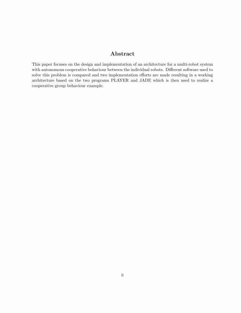
The PAMI lab has different robots, the ones used mostly are the three MagellanPro robots1. Theywere produced by Real World Interfaces,Inc.1. These cylindrical robots are about 50cm high andabout 40cm in diameter and have a full set of 16 sonar, 16 infra-red and 16 bumper sensorsarranged around the body. Those sensors are operated by two dedicated embedded controllerswhich are connected to a standard PC inside the robot. This PC is running the operating systemRedHat Linux 6.2. It is also equipped with wireless LAN, an odometer and a video camera on apan-tilt unit. No other harddrive than the harddisk is available. Direct connections to the robotcan be made through a serial connection and a terminal emulator or by connecting a standardPC screen and keyboard.Due to the linux installed the robot is also accessible via ssh or telnet. The robots names are mag1,mag2 and mag3, they have a DNS entry for mag1.uwaterloo.ca and mag2. and mag3. respectively.
The other kind of robot I used in my project was an ATRV mini by the same company, iRobot.The ATRVs in the lab are not as well equipped with sensors as the smaller Magellan Pros and areby design more outdoor robots with big wheels which should allow them to manoeuvre outsidein rougher terrain. The default sensors of the ATRVs are 16 sonar sensors spread around the
1Real World Interfaces is now called iRobot and discontinued their series of research robots
1
1.2 The lab 1 INTRODUCTION
Figure 1: iRobot Magellan Pro robot
2

1.2 The lab 1 INTRODUCTION
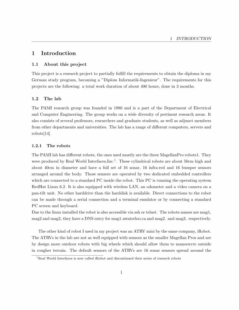
Figure 2: iRobot ATRV mini robot
robot with a strong emphasis on the front section. The unit is also heavier than the Magellan Prowhich weights about 20 Kg, it weights around 40 Kg. I used those robot to experiment with theLinux installation process and the PLAYER configuration. To test the PTZ and camera interfaceof PLAYER I temporarily installed the Sony camera of mag3 on the test ATRV, min1.Their DNS names are min1, min2 and min3.
1.2.2 The mobility software
The original software by the producer of the robots is called mobility. It allows access to thelast measurements taken by the sensors and provides an easy API for accessing informations likethe current position of the robots or sensor values. It also provides a central naming service to
3

1.3 Overview over work done so far in the PAMI lab 1 INTRODUCTION
communicate with the robots. As it is a binary only software (”black box”) its use to researchersis limited. To establish accurate sonar perception and calibrated infrared perception for exam-ple, considerable time and effort is required because information about the time at which eachindividual sonar transducer is activated is inaccessible through the binary-only software layer[13].
1.3 Overview over work done so far in the PAMI lab
This section will give a short overview of the preview work done with the Magellan Pro robots.It will concentrate on the projects which immediately preceded my work in the last year.Every project has in common that the software was developed from scratch and specifically forthe project’s goals with a very limited use for the following projects. After the switch from themobility software to C++ programming a big part of the programming work was spent for themessage exchange and inter-robot communication in the projects with group behaviour. The orig-inal goal of my work, the combination of different already programmed behaviours would requirea major extension of existing communication code and would allow later groups to concentratemore on higher level group behaviour work rather then low level networking.The goals and design of my project are described in the corresponding sections 3 and 4
1.3.1 early 2004: 4th year project on Co-operative Robot Behaviour
Four students (Christpher Book, Jean-Paul Haddad, David Henderson and Andrew Sheppard)started with programming cooperative group commands like a triangle formation using the mo-bility software. They implemented algorithms to make cooperative decisions and to communicatebetween the robots. At the end of the project the robots were able to form a straight line with agiven length and a triangle with a given side length.
1.3.2 RobotManager
Ben Miners wrote a replacement for the closed source mobility manager in C and C++ to have amore flexible and better maintained system. It enables direct access to the sensor data and otherfeatures. Communication through Corba is replaced by sending direct Messages and commandsper telnet. This new softare layer allowed precise calibration of the robots sensors. Documentationis available in the form of a descriptive PDF file and automatic documentation generation from thesource files by DOxygen. Behaviour of robots can be added by simple C++ programs which use
4

1.3 Overview over work done so far in the PAMI lab 1 INTRODUCTION
the robotmgr framework and are run directly on the robot. No naming service like in mobilityis provided, the inter-robot communication is planned but not fully implemented. My initialwork was done using RobotMgr, I will explain more about RobotMgr later when I introduce thesoftware used in section 2.5.
1.3.3 late 2004: Work done by Slim and Raydan
Slim and Raydan ported the code from the first 4th year project to the new robotmgr andextended it to a greater variety of commands such as the implementation of an algorithm toshoot an orange football (basketball). The second program they tracks a moving basketball withthe cameras of both robots. The last program located the previously unknown position of therobot by recognising landmarks at known positions and deducting the own position from thoseinformations.
1.3.4 Geometric landmark discovery
Ben Miners and other wrote code to detect a special artificial landmark which is recognisableregardless of the angle of the viewer, in realtime. This is based on a paper from Briggs, Scharsteinand Abbott [4]. The landmark consists of an p-similar pattern which can be detect reliableand fast from widely differing angles and distances. The landmark can have another barcodeincluded which enables to identify this special landmark and give more data about it. After thep-similar pattern is recognised the additional barcode is located and analysed. This gives youthe opportunity to use more than one landmark, for example to help the robot to navigate in aroom.
1.3.5 Multiple agent architecture for a multi robot system
Bram Gruneir worked with the Magellan pros as part of his master’s thesis about a multiple agentarchitecture for a multi robot system. He used JADE and Robotmgr to control and coordinatethe robots in a group with a dynamical number of 1-3 robots. The report about his work isunpublished so far and I haven’t got a copy of it, so all I could use of his work was his sourcecode and what I got from a presentation from him about his work. There is a video of his robotsbuilding a formation around a special coloured can on the PAMI website[14]. JADE is introducedin section 2.5.
5

2 BACKGROUND
2 Theoretical background
This chapter will introduce basics about robotic software architectures, cooperation between therobots and possible problems in that area. To conclude a selection of software I found in literatureis compared, among them the later used PLAYER and JADE.
2.1 Robotic software architectures
A software architecture in robotics defines the key components the software running to controlthe robot and the way they interact. It also suggests ways how to use this combination in itsintended way for fulfilling tasks. It is common to differentiate distinct levels in the architecture.As stated in [16, p.932]
Modern-day software architectures for robotics must decide how to combine reactivecontrol and model-based deliberative control. In many ways, reactive and deliberatecontrol have orthogonal strengths and weaknesses. Reactive control is sensor-drivenand appropriate for making low-level decisions in real time. However, reactive controlrarely yields a plausible solution at the global level, because global control decisionsdepend on information that cannot be sensed at the time of decision making. Forsuch problems, deliberate control is more appropriate.Consequently, most robot architectures use reactive techniques at the lower levels ofcontrol with deliberate techniques at higher levels. [...] Architectures that combinereactive and deliberate techniques are ususally called hybrid architectures.
2.1.1 Control localization in behaviours
A third layer which is often added between the two mentioned layers is the executive layer whichis the translator between the reactive and deliberate layer. As an example the executive layercan receive waypoints which are generated by a long term path planner in the deliberate layerand choose an appropriate way to reach this waypoint, then giving the associated commands tothe executive layer.Following [19, p. 291] wanted features of a well-designed architecture (in this case a navigationarchitecture) are:
1. Modularity for code reuse and sharing
6

2.1 Robotic software architectures 2 BACKGROUND
Basic software engineering principles embrace software modularity, and the samegeneral motivations apply equally to mobile robot applications. But modularityis of even greater importance in mobile robotics because in the course of a singleproject the mobile robot hardware or its physical environmental characteristicscan change dramatically , a challenge most traditional computers do not face. Forexample, one may introduce a Sick laser rangefinder to a robot that previouslyused only ultrasonic rangefinders.
2. Control localization
Localization of robot control is an even more critical issue in mobile robot nav-igation. The basic reason is that a robot architecture includes multiple typesof control functionality (e.g.,obstacle avoidance, path planning, path execution,etc.). By localizing each functionality to a specific unit in the architecture, weenable individual testinf as well as a principled strategy for control composition.[...] It is also valuable to localize such high-level decision-making software, en-abling it to be tested exhaustively in simulation and thus verify even without adirect connection to the physical robot.
A general tool to implement control decomposition are behaviours, which incorporate a specificcomponent of the architecture.
2.1.2 Temporal control decomposition
A possible axis along which we can discriminate the control architecture into distinct behavioursis the time constraints on the components. High level path planning components are only goingto be called every minute or 10 minutes, whereas low level sensor handling and motor control willbe updated in frequencies of 10 Hz and faster as depicted in figure 32. Those low level processalso have real-time demands to the scheduling while processing them is usually quite fast. forthe path planning no real-time requirements are made, but the computation might take a whiledue to its complex nature depending on the algorithm used. An example for a more complexarchitecture to combine different behaviours and motivations is the ALLIANCE[2] architecture
2Based on [19, p.294], numbers changed slightly
7

2.2 Cooperation among a group of robots 2 BACKGROUND
Figure 3: Schematic of four level temporal decomposition
2.2 Cooperation among a group of robots
Without going too much into notions of multibody agent planning some basics will be explainedhere. As stated in [16, p.450]
Plans can be constructed that specify actions for both players on the team [in thatexample]; we will describe techniques for constructing such plans efficiently. Efficientplan construction is useful, but does not guarantee success; the agents have to agreeto use the same plan! This requires some form of coordination, possibly achievedby communication.
The mechanisms to achieve coordination between the agents can vary. In the simplest casethere are domain-specific conventions which force the agents to make the right decisions, alsoknown as social laws if they are widely adopted by everyone.More abstract mechanisms are domain-independent conventions such executing the same algo-rithm with same inputs on every robot as described in [16, p.452]
For example, if each agent runs the same multibody planning algorithm with the sameinputs, it can follow the convention of executing th efirst feasible joint plan found,confident that the other agents will come to the same choice A more robust but moreexpensive strategy would be to generate all joint plans and then pick the one, say,whose printed representation is alphabetically first.
8

2.3 Practical problems in group communications 2 BACKGROUND
More advanced coordination strategies often emerge through evolutionary processes which resultin the flocking behaviour of birds, for example. Because every agent is following a simple set ofrules an emergent behaviour can be recognised in the group.
2.3 Practical problems in group communications
A problem in the coordination of a group of autonomous robots is the communication betweenthem. If there is a central infrastructure to provide data in a ”black board” fashioned way, likethe mobility software does, data exchange is relatively easy. If a more robust and decentralisedapproach is wanted the number of messages which have to be exchanged to get a common dataknowledge in the group is increasing exponentially, or a broadcasting solution has to be chosen.The broadcasting solution would send the data to a certain address in the network which causesevery robot to receive those messages. This makes sending the message easier but the amount ofmessages sent from the network switch to the robots remains the same, effectively only halvingthe amount of messages sent.To further lower this amount more intelligent strategies have to be used such as sending messagesonly to certain robots, for example the immediate neighbors. This way the amount of messagessent can grow linearly with the amount of robots in the group.
2.4 Properties of the task environment
The properties of task environments can be categorized to determine the appropriate agent designand the application of techniques for the specific agent. These categories are taken from [16, pp.40]The world in which the mobile Agent, the robots, will act is assumed with the following informalstatements:
• It is only partially observableNoisy sensors will prevent the robot from having a full exact overview over its surroundingat every moment, the tilt angle of the camera only allows the camera to view a certainrange and the robot can’t detect anything when its sight is blocked by obstacles such asother robots, for example.
• Its behaviour is deterministicWe assume no outside Agents or actions change the environment after the robots have beenstarted, the next stage of the environment is always completely determined by the actions
9

2.5 Overview over software used in this area 2 BACKGROUND
of the robot. An exception to this is the scenario where the robots should track a movinglandmark.
• The task environment is episodic.The different tasks will be well separated from each other, so the agent’s experience isdivided into atomic episodes.
• The task is semidynamic. It is semidynamic in that aspect that the world around the robotwill not change while time is passing. The performance score of the robot’s behaviour willdepend on the time though, so the task is semidynamic. In some applications the worldis dynamic, specifically in those cases where the robots are supposed to follow a movinglandmark.
• The time during the comletion of the task is continuousBoth the movement of the robots and other objects are continuous in time, so the state ofthe environment is changing in a continuous time. The perceptions are continuous in theway they measure angles, get pictures from the PTZ camera and get sonar feedback.
• Finally the setup has multiple, cooperative agents.No competing agents try to maximise their performance measure, thus minimising ourperformance measure, communication is needed to interact with the other agents to reacha common goal, a shared performance measure for example.
2.5 Overview over software used in this area
The advantages of a platform independent multi-robot system which enables flexible reuse andinterchangeability of code have been recognised by many groups, thus different software solutionswere created. They all have their own distinct features which will be compared now. My goalwas to find a software platform allowing the flexible reuse of existing solutions, even if they wereoriginally written for a different platform. Such a software would allow an easy exchange of resultsbetween developers of different robotic systems. This software should support the robots in thePAMI lab, of course. Additional comparisons between single and multiple agent software alongwith a proposed set of comparative dimesions can be found in [1]
10
2.5 Overview over software used in this area 2 BACKGROUND
2.5.1 ARIA
ARIA[3] is a Object Oriented interface to ActivMedia mobile robots, this way of little directuse for our iRobot robots, but it uses basic ideas which can be considered for a framework forrobotmgr as well. ARIA can be used to read sensors and drive the robot with custom actionsor to merely send and receive commands. It does threading via its own wrapper around linuxpthreads and has reference documentation generated via auto documentation in the code. Todetermine the action which is to be executed priorities are used. It is licenced under the GNUGPL, allowing us to view and reuse the sourcecode. Other interesting features:
• Built-in socket layer eases inter-program communication via network
• Built-in actions for obstacle avoidance
2.5.2 ALLIANCE
ALLIANCE[2] is a control architecture for fault tolerant, reliable and adaptive cooperation amongsmall to medium sized teams of heterogeneous mobile robots, performing (in dynamic environ-ments) missions composed of independent tasks that can have ordering dependencies. ALLIANCEuses a ”intentional” cooperation approach as opposed to a swarm-type approach. This approachwas chosen to enable smaller teams of heterogeneous robots to efficiently perform a given task. Akey issue here is the allocation of a task to the optimal robot to solve this task. This is solved witha behaviour based approach without a central control. The robots use mathematically modelledmotivations such as impatience and acquiescence to achieve adaptive action selection. Lower levelbehaviours
2.5.3 MARIE
MARIE[12] is a robotic development and integration environment focused on software re-usabilityand exploitation of already available APIs and middlewares frequently used in robotics. MARIEacts as the centralized control unit using the mediator design pattern for distributed system tocoordinate global interactions between different, normally incompatible applications. By usinga solid and generic communication framework Marie aims to create a very flexible system thatwill support a wide variety of applications. To realize these goals each program to be used withMARIE must have a clear method of interactions that MARIE can use for integration. An
11

2.5 Overview over software used in this area 2 BACKGROUND
implementation integrating different programs such as FlowDesigner/RobotFlow, ARIA, PLAY-ER/STAGE/GAZEBO, CARMEN and ACE is available for download on the projects website.This implementation is using a Magellan Pro like the ones in the PAMI lab as the hardware basis.The role of the components is:
• ACE is used to create communication framework between MARIE’s components
• Navigation and localization are done with CARMEN
• Expressions control, behaviors control (avoid, wander, rest) and joystick control are donewith RobotFlow/FlowDesigner
• Player device abstraction allows to use the same system configuration to run in simulation(with Stage,Gazebo) and on a real robot (Magellan Pro)
• Aria device abstraction allows to use the same system configuration to run in simulation(with SRIsim) and on a real robot (Pioneer)
• Application control, joystick control and manual expression control are done with wxWid-gets.
2.5.4 OROCOS
OROCOS is an initiative to produce a functional basis for robotic software systems. Based onRTAI (Real-Time Application Interface is a hard real-time extension to the Linux kernel) it isable to offer an open source hard realtime control architecture for several machine types.This is a very basic software intended for people writing realtime device drivers and using all theoffered features such as advanced control methods with asynchronous data access. Cons:small control problems do not require either real-time, or advanced control methods with asyn-chronous data access. For these cases, OROCOS can be overkill.
2.5.5 MAGE
MAGE[11] is an open source replacement similar to the RobotMgr program, but with certainlimitations in the context of unsolicited/low latency data acquisition, it also lacks full DVI-30ptz support. Mage is basically a very simple c interface to the rFlex controller on our robots.It was developed during the summer of 2000 for the authors entry into the AAAI mobile robots
12

2.5 Overview over software used in this area 2 BACKGROUND
competition, later he improved it somewhat for his thesis work.Because of the limitations Ben Miners decided to write an own implementation, the RobotMgrsoftware. MAGE also seems to be discontinued, as the latest release is from Juli 2004.
2.5.6 RobotMgr
RobotMgr is the replacement Ben Miners wrote for the closed source MOBILITY manager byiRobot. It was written in C and C++ to have a more flexible and better maintained system withfull access to the source code. It compiles both on the original RedHat 6.2 of the robots withwhich they were delivered as also with the Fedora Core 3 of my test robot. Its requirements onlyinclude apart from the obvious GCC the GNU Common C++ library. GNU Common C++ isa C++ framework offering portable support for threading, sockets, file access, daemons, persis-tence, serial I/O, XML parsing, and system services. I compiled robotMgr successfully with thelatest version of GNU Common C++, 1.3.1.
Another goal apart from the access to the source code was to enable direct access to thesensor data and other hardware devices of the robot. While sensor readings in MOBILITY areonly updated if new values are available and in a more irregular pattern RobotMgr allows directaccess to the sensors. This allows precise calibration of the robots sensors, which was done byBen Miners for one of the Magellan pros.
MOBILITY’s communication through Corba is replaced by sending direct messages with TCPor UDP and commands per telnet. The protocol used to send messages can be chosen betweenUDP or TCP by the code designer to allow both fast or secure message delivery. Messages canbe send through the abstract concept of channels to which the robot subscribe to send messagesto or listen to new messages. This way applications like a remote monitoring tools which displaysall sensor values of the remote robot is possible and also implemented fully working.
Documentation is available in the form of a descriptive PDF file and automatic documenta-tion generation from the source files by DOxygen.
Behaviour of robots can be added by simple C++ programs which use the robotmgr frame-work and are run directly on the robot. These behaviours are started by either using the telnetinterface or calling them directly from a C++ program. They are scheduled as parallel threads
13

2.5 Overview over software used in this area 2 BACKGROUND
Figure 4: Schematic of the RobotMgr program
14

2.5 Overview over software used in this area 2 BACKGROUND
automatically as their class is an extension of the pThread class and have a function which iscalled upon the reception of new data from the rFlex device.
No naming service like in MOBILITY is provided, the older project all used hard coded robotnames and addresses. The robots announce the startup of robotMgr on a public channel, butthis information has not been used so far.
While testing out RobotMgr’s features with small test programs I encountered several prob-lems with the message handling and remote control of other robots. Ben Miners kindly helpedme to solve some of those problem, but some remained. Due to these reasons I tried to findother software to control the robots and discovered PLAYER which is described in the followingsubsection.
2.5.7 PLAYER/STAGE/GAZEBO
These three programs are developed to be used together to write code to program both simulatedrobots and their real counterparts. PLAYER is the server part which either runs on the robot andgives access to its hardware and communication features or uses simulated sensors when run on anormal PC. To run the simulation either STAGE or GAZEBO is used, where STAGE focuses onsimulating the environment just enough to let simulated robot use its sensors, this way enablingthe fast simulation of bigger groups of robots in 2D GAZEBO is the high fidelity 3D counterpart,used to simulate only a few robots with much better environmental resolution.PLAYER provides client libraries for several programming languages such as C, C++, Tcl, LISP,Java, and Python, allowing to combine different pieces of software to a whole project and utilizethe relative strengths of the programming languages.
PLAYER also provides driver for a whole range of hardware devices such as the MagellanPro’s rFlex interface and Sony PTZ cam.PLAYER drivers interesting in the scope of this project are the following:
• camerav4l:The basic, uncompressed raw camera images as they are provided by the LINUX v4l2 driverof the capturing card.
• cameracompress
15

2.5 Overview over software used in this area 2 BACKGROUND
This a driver for compressed camera pictures from a source using the camera interface. Thisdriver can be used to display camera images remotely without stressing the network toomuch, although the compressing action does stress the robot quite a lot.
• cmvisionA driver which takes the camera stream from camerav4l for example and uses the CMVisionalgorithm to detect blobs on the picture.
• rFlex:The most important driver enables interfaces to all devices in the robot controlled by theon-board rFlex controllers.
PLAYER runs on Linux and uses the communication features offered by it.Because of the abstraction level of player and it being open source software programs developedby other groups can be used easily to enhance own projects. Integrated into PLAYER are algo-rithms such as a goal-seeking obstacle avoidance algorithm (VFH) or an Adaptive Monte CarloLocalization (AMCL).At any time a player server is running a client called playerv can connect and display the actualrobot’s view of the world via his array of sensors. It is also possible to give simple move commandswith this interface.
2.5.8 JADE
The Java Agent DEvelopment platform[7] provides a FIPA3 specifications compliant frameworkfor complex agent structures. Messaging is handled using FIPA ACL as the language to representthe messages. Each agent is represented by a globally unique adress called AID which containsthe name of the agent and the host and port name on which the agent is listening. Agents canannounce services at a global yellow page service running in the root container.The agents use threaded tasks called behaviours in JADE, which are scheduled by a simple roundrobin algorithm and are non-preemptive, so one blocking behaviour can stop the whole robot untilit is unblocked. There are different kinds of behaviour templates to choose from, the differencesare for example the way they terminate (never, after one execution, user-defined).
3The FIPA is an IEEE Computer Society standards organization that promotes agent-based technology and theinteroperability of its standards with other technologies.
16

2.5 Overview over software used in this area 2 BACKGROUND
JADE is usually used with purely software agents as it can be seen in their example files given onthe webpage. Those simple examples include the simulation of spreading of information througha group at a gathering or the dynamics of a market with groups of sellers and buyers for goods.In those cases quite a large number of agents do rather simple tasks, unlike the way this projectwill use JADE.
17

3 GOALS OF THIS RESEARCH WORK
3 Goals of this research work
During this research and project work a framework for future use with the robots will be writtenin an iterative process using a rapid prototyping style software engineering approach.The goal is to introduce a complete set of software to simulate, develop and test cooperativebehaviours with reusable components. This set of software should allow easy modification anddebugging while providing a high level communication interface to others robots in the group.The software should allow behaviour of the robots with emphasis on cooperation between themand the robots acting autonomously without the aid of a central server. Every robot will betreated equally by design and no predefined leader dictates the group’s actions.This architecture will then be implemented and a complex group behaviour written for it todemonstrate its capabilities.
3.1 Framework for recognition and behaviour
A multi layered framework as described in section 2.1 will be planned and implemented. Thearchitecture consists of two layers of software which are the low level robot control and the higherlevel execution code.
3.2 Application of cooperative group behaviour
Initially this was one of the first goals of this project because it was assumed that I could usethe work of previous groups and combine it to a new complex behaviour rather easily. It wassupposed to combine the artificial landmark detection with the group formation command whichwere both described in section 1.3, but since I switched the used software platforms this applica-tion is a completely new design. The new goal is thus:The group of robots will try to detect the landmark, the robots with the least distance to it isthen selected as the group leader. The other robots will build a certain formation around theleader while it is following the landmark as it is moved by a user. Possible extensions are therecognition of a pattern added to the landmark which will then define the kind of formation buildby the group or a certain behaviour when the landmark is moved in between the group or veryclose to another group member. Another extension of this idea is to change the leadership againshould the landmark be moved so that its distance to the leader is greater than to another robot,this robot will become the new leader.
18

3.3 Subgoals 3 GOALS OF THIS RESEARCH WORK
3.3 Subgoals
In order to implement the comlex behaviour described above small subsets were implementedand extended step-by-step following a rapid prototyping software engineering approach.To start those smaller behaviours special messages have to be sent to the running agent, containinga keyword each and variables in some cases which are separated by a colon.The subgoals are described following:
3.3.1 Goto behaviour
A behaviour which will accept coordinates as the input and will then compute the fastest way togo to this position and drive it with the robot. This will not include any collision detection orpath planning.
3.3.2 Follow behaviour
A leader robot will be set arbitrarily and a robot follows this leader in a certain distance whereverit goes. To move around a similar algorithm to the Goto behaviour will be used, again withoutcollision avoidance or path planning.
3.3.3 FindBlob behaviour
The robot tries to detect a landmark of a certain color or pattern in the environment and focuseson this landmark. The robot will also follow the landmark if it is moving and will try to keep acertain minimum and maximum distance.
3.3.4 FindClosest behaviour
This subbehaviour will communicate number (e.g, the distance to a landmark) between robots,then perform a computation on these numbers and get an AID (global unique agent name) as aresult.
3.3.5 Lead & Follow behaviour
These subbehaviours will enable one robot to lead all other robots in the group and the others tolisten to his movement commands. All the leader is going to do is propagate his current position
19

3.3 Subgoals 3 GOALS OF THIS RESEARCH WORK
to the following robots, they will then compute their target position on their own and issue thecorresponding commands to get to that position.
20

4 DESIGN
4 Design
The original design was my design for the first third of this project, when I assumed I would usethe combination of RobotMgr and self written C++ communication like the previous projectsdid. These would be used to build the complex behaviours while reusing the already writtensubbehaviours by previous groups. As explained in section 5.1 I decided to switch to the morepromising combination of PLAYER and JADE. Therefore the original design had to be revisedand is given in section 4.2. To show the original ideas on which the revised design was based Iwill explain the first design here, although it was not implemented in a fully working way.
4.1 Original design for C++ and robotmgr
To avoid ”reinventing the wheel” during the research a modular framework for recognition andbehaviour is planned. It will provide a way to communicate for the different running tasks androbots in the group. A central server program on each robot representing the intelligent agentwill coordinate the actions and decide which movement to make. Smaller Subprograms, runningin different threads will be able to access the sensor data and propose possible movements to theserver, weighted with a value corresponding to the importance of this action. The server will thenselect the most important action and execute it. This will enable the brake module to stop therobot when an object was hit, for example. The framework will do threading via its own wrapperaround linux pthreads, or robotmgr’s taskBase pthread wrapper.Due to the modularity components will be easily to replace by a different implementation. Theseare the most important components I had in mind for the framework:
• Basic Behaviour:Behaviour to enable the robot to navigate without destroying anything such as stoppingwhen bumping into anything or collision avoidance via sonar.
• component for object recognition:Modularity will allow the recognition of objects like an orange ball, any color or landmarkslike the artificial p-similar ones. This module will set the robot in a state where he scanshis environment once and align to the object so that it is in the middle of his point of view.From the angle of the camera, the angle of the robot, the known position of the robot and
21

4.1 Original design for C++ and robotmgr 4 DESIGN
the size of the object the position can be estimated. If multiple robots located the objectthen the localisation can be even improved by combining the gathered data.
• component for object tracking:Probably not more than one module is needed here, this part of the program makes surethat the robot follows the object with the camera. In the simple version this happens byscanning every image and trying to center the landmark. A more complex version willestimate the movement of the landmark and try to take up less computing power while stilltracking it. This module could also be seen as en extended version of the object recognitioncomponent.
• component for task assignment: Decides which robot in the group is to do which task, tasksare defined in the behaviour modules. To decide this cost functions well be implementedto compute the optimal decision in regard to either speed, energy consumption or otherpriorities.
• component for behaviour:Different models of behaviour like ”follow the object”, make a certain formation, shoot asoccer ball, give out information about the object etc.Some of this behaviour is already implemented somewhere but ”hard-coded” into smallprograms, the goal is to be able to reuse these components for the next object recogniserdeveloped or to choose from different behaviours easily.
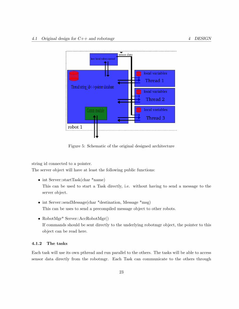
As you can see in figure 5, a central core of the software framework will be the server part.The functions of each component is going to be explained in the next subsections.
4.1.1 The server object
The server object is instantiated by the program written by the user or can be instantiated onits own. It will take care of setting up the robots rFlex controller as well as starting a listeningthread to receive messages of this framework. For this task an own communication pthread isstarted which receives the messages and dispatches them by calling functions of the server objectdepending on the contents of the message.The server object will keep records of the tasks started contained the pointers to the tasks, somessages can be forwarded to them. This is symbolized in the schematic in figure 5 by Thread
22
4.1 Original design for C++ and robotmgr 4 DESIGN
Figure 5: Schematic of the original designed architecture
string id connected to a pointer.The server object will have at least the following public functions:
• int Server::startTask(char *name)This can be used to start a Task directly, i.e. without having to send a message to theserver object.
• int Server::sendMessage(char *destination, Message *msg)This can be uses to send a precompiled message object to other robots.
• RobotMgr* Server::AccRobotMgr()If commands should be sent directly to the underlying robotmgr object, the pointer to thisobject can be read here.
4.1.2 The tasks
Each task will use its own pthread and run parallel to the others. The tasks will be able to accesssensor data directly from the robotmgr. Each Task can communicate to the others through
23
4.2 Revised design for Java, JADE and PLAYER 4 DESIGN
sending a message which is then forwarded to the target thread by the server object. Thus thetask will provide a function such as
• int Server::getMessage(Message *msg)This enables the task to receive messages objects.
4.1.3 The message class
The Message object consists of 5 char arrays which allow the flexible use of this message. Themessage definition is going to be as following:
class Message {public:char senderHost[5]; e.g. mag1char targetHost[5];char targetThread[10];char targetVariable[10];char dataString[10]; flexible data payload of msgPoint dataPoint; Point data payload of msg
4.2 Revised design for Java, JADE and PLAYER
The code for this task will only based on the work done by the previous groups in a very smalldegree as they mostly used a different programming language and most important a differentrobot management platform, robotMgr instead of PLAYER. The reason for my switch to thePLAYER platform will also be explained in section 5.1.3.
The programming language which will be used to realize the framework is Java as this issupported by both the main software components used, PLAYER and JADE. JADE will beused as the platform and framework for inter-robot communication , it also provides all thenecessary means to start and coordinate behaviours and much more. The Java code should becompileable on any POSIX machine which provides the necessary libraries. The emphasis was onobject oriented code which allows to modularize smaller parts and change them without havingto change any other code.
24

4.2 Revised design for Java, JADE and PLAYER 4 DESIGN
Figure 6: Schematic of the revised two-tier architecture design
The architecture will be a two-tier architecture as described in the section 2.1 and similar to theone discussed in [19, p.300]. It is displayed in figure 6.
The JADE part is displayed in detail in figure 7. The PLAYER part takes movement com-mands for the motor and other devices such as the PTZ unit and provides regular updates ofsensor data to the PlayerClient proxy in the PlayerAgent Java object. A central data storage, aJava hashmap, in the PlayerAgent object allows the shared storage of inter-behavioural data anda list with AIDs of known robots is kept in the playerAgents array. Every behaviour, displayedhere on the right with some of the more important ones such as the behaviour updating the listof known agents and the one receiving position updates and other data from those agents, storingthem in the hashtable. The number of running or possible behaviours is not limited by the designbut by the available hardware resources.
4.2.1 PLAYER part
Effectively the PLAYER software is replacing the part of the robotMgr in the original design dueto reasons explained in section 5.1.3. The PLAYER program itself is running out-of-the-box andneeds only little customisation to the robot on which it is used, the drivers which should be usedhave to be declared and initialized with configuration values in some cases. I made the followingsetup for the PLAYER server:
25

4.2 Revised design for Java, JADE and PLAYER 4 DESIGN
Figure 7: Schematic of the JADE part in the revised design of the software architecture
26

4.2 Revised design for Java, JADE and PLAYER 4 DESIGN
The PLAYER server will be running on every robot and listen to the port 6665, which is allowedby the firewall of the robot. The configuration file of the robot will define support for the differentsensors the robot provides and also declare the position of those sensors, so that the visualisationin other programs such as playerv will display the correct sensor reading. The interfaces providedby PLAYER on a Magellan pro robot are the following:
• positionThis most basic interface allows the reading of odometry data from the robot as well thesetting of the speed and direction of the motors.
• camera:0The basic, uncompressed raw camera images as they are provided by the LINUX v4l2 driverof the capturing card.
• camera:1This is an interface to compressed camera pictures from the same source as camera:0. Iused this together with playerviewer to see the live camera stream on a remote copmuter.
• blobfinderThis again uses the camera stream from camera:0 to detect colored blob in the picturesusing the CMVision algorithm.
• sonarThe array of 16 sonar sensors on the Magellan pro robot. Although they are managed bytwo separate embedded boards on the robot, they are accessible through one interface inplayer
• IRThe array of 16 IR sensors on the Magellan pro robot. Although they are managed by twoseparate embedded boards on the robot, they are accessible through one interface in player
• BumperThe array of 16 bumper sensors on the Magellan pro robot. Although they are managedby two separate embedded boards on the robot, they are accessible through one interfacein player
27

4.2 Revised design for Java, JADE and PLAYER 4 DESIGN
4.2.2 JADE part
The framework for the different behaviours is based on JADE and the Java-Client for the Playersoftware also described in section 2.5. JADE allows a very easy way to receive and send messages,organise and manage multiple threads (called Behaviours here) and testing using the dummy agentto simulate messages sent in the group of agents. Behaviours are scheduled by a simple roundrobin algorithm and are non-preemptive, so one blocking behaviour can stop the whole robot untilit is unblocked. There are different kinds of behaviour templates to choose from, the differencesare for example the way they terminate (never, after one execution, user-defined).On every robot one JADE agent will be running which hosts a set of the following behaviours.The robot hardware will be controlled by the basic behaviour which issues the final movementcommands to it.
• Basic Behaviour:Behaviour to enable the robot to navigate without destroying anything such as stoppingwhen bumping into anything or collision avoidance via sonar.
• component for object recognition:Player offers different drivers to provide the so called blobfinder interface, which can beconsidered as an object recognition interface. I used the CMVision driver which uses theCMVision algorithm to extract blobs of colours with a certain given range of YUV values.To use the artificial landmark detection algorithm the driver part in PLAYER would haveto be modified, thus returning a blob value with a certain color when an artificial landmarkhas been detected in the camera stream.
• component for object tracking:Together with the blobfinder, this behaviour uses the position proxy to get the best viewof the object. The PTZ unit is not used so far because this would require addition effortfor determining the movements of the robot.
• component for task assignment:In the case of the group following the blob one of these components determines the leader,another one determines the optimal position of the following robots in the formation.
• component for behaviour:This component is implemented as behaviours in JADE like most of the other components
28

4.2 Revised design for Java, JADE and PLAYER 4 DESIGN
as well. The modular architecture of JADE allows behaviours to control other behaviours,this is what these components do. They coordinate running behaviours, start new ones andalso provide the basic message receiving capabilities of the agents.
The first complex behaviour I implemented was a behaviour which starts by every robot lookingfor a landmark, then communicating if they found it, selecting a leader and following the landmarkin a formation.
4.2.3 Java-client for PLAYER
To be able to access the PLAYER server which is written in C++ the third party Java-client[10]for PLAYER is used. Basically the Java-client is just a very simple Java interface exchangingmessages with the PLAYER server. A proxy for every PLAYER device has to be instantiatedat the beginning of the program, later simple function calls to those proxies allow communica-tion with the PLAYER server. No special configuration is necessary and the use is absolutelytransparent.
29

5 IMPLEMENTATION
5 Implementation
5.1 First Implementation with C++ and RobotMgr
5.1.1 First steps with RobotMgr
First steps with the software used in the previous projects were done by modifying existing codeto enhance the features. After getting familiar with existing examples for the robotMgr softwarean own behaviour was added which would use the previously unused bumper sensors on the robot.The new behaviour would run in parallel with other running behaviours and listen on bumpersensor events. In the case of a bumper touching a nearby surface a variable would be set whichthen stops the robot,causes him to turn around, go backwards or other reactions defined in themain program.Next programs which were written for the robotMgr were test programs to remotely control otherrobots or exchanging messages between them. Most of those smaller test programs remained un-finished as the underlying robotMgr framework was not working completely.
5.1.2 First steps with C++ networking
On the higher level of group control I started with reading and modifying the existing programsfrom Slim and Raydan. It quickly showed that those programs were written to fit exactly theirrespective purposes and extending them to include other behaviours such as the landmark discov-ery proved to be much more complex then I expected. The existing way those programs workedonly allowed a very limited way of reacting to events, so I decided to only keep small parts of thecode and re implement most of the other parts to allow a greater flexibility for future behaviours.Special attention was given to have a flexible message format to use with different behaviours tocommunicate between the robots, a sort of automatic behaviour to synchronize sensor data be-tween the robots and threaded handling of simultaneous behaviours. The original design includeda descriptive outline to those features.
5.1.3 Reasons for the switch of the underlying software
Both the message handling and the threading quickly grew more complex and required most ofthe developing effort in contrast to the original goal of this research work, an autonomous group
30

5.1 First Implementation with C++ and RobotMgr 5 IMPLEMENTATION
behaviour architecture. To avoid this problem an existing framework with easy to use communi-cation means between the robots is needed. A research on existing multi-robot communicationframeworks in C++ brought no new discoveries and so I decided to reconsider the use of a dif-ferent Programming language than C++. At that point JADE was suggested by my colleaguesafter a presentation of me about PLAYER.PLAYER was chosen as a replacement for robotmgr for several reasons.
1. As Ben Miners is just finishing his master’s thesis he was very busy during all the time ofmy project and will be probably to provide even less support for his program after he hasleft the university. There is no existing programmer’s guide to the robotMgr and even withsome mail support from Ben it took me quite some time to write basic programs to test thesoftware’s capabilities and understand its possibilities. There is an automatically generatedDOxygen documentation available, but this won’t help to much with basic understandingof the software.PLAYER on the other hand has several documents such as papers and programmers guidesto help the understanding of the basic structure. An active mailing list is trying to helpusers with problems and advices. The mailing list archive is also a valuable knowledge base.The software is under constant development and this way improved with every new release.
2. PLAYER features 2D and 3D simulation using the STAGE and GAZEBO software. Thisfeature is an invaluable help in developing complex behaviours such as group behaviourwithout risking the expensive hardware in possible collisions or accidents. Large populationscan be simulated without the necessity to buy those robots, software can also be tested ondifferent hardware than the originally intended one by using the interface abstraction fordevices. Additional hardware such as SICK laser scanner can be tested for their efficiencyin improving the robots capabilities and, if they are bought later, used right away withthe already written software. The software could even be used with classes to allow alarger number of students to learn about this topic and have their own solutions to givenproblems. Also different environments such as close quarters in a hospital or an open fieldcan be conveniently simulated by just drawing the map with a graphic or CAD program.
3. As mentioned above the PLAYER software already supports a vast collection of hardware,so future purchases of a laser range finder for example will work right away in the robots- without having to modify the robotMgr, just by changing some lines in the PLAYERconfiguration files.
31

5.2 Preparation of the robots for PLAYER 5 IMPLEMENTATION
4. This concept also allow the exchange of an complete implementation of some project withother researchers or people interesting in it - all they have to provide is a working installationof PLAYER, then they could just execute the Java binaries of my project for example.
5. PLAYER’s included algorithms for tasks such as a goal-seeking obstacle avoidance algorithm(VFH, Vector Field Histogram) or an Adaptive Monte Carlo Localization (AMCL) add awhole new dimension of possibilities for work with the robots in the PAMI lab. Thisfunctionality will robotMgr probably never be able to offer - as it is just a small projectcompared to PLAYER.
5.2 Preparation of the robots for PLAYER
5.2.1 Requirements of PLAYER
The requirements for PLAYER include ”a recent version of GNU GCC” which was not availableon the about 3 year old RedHat installed on the robots since they were delivered. I also foundno way to update those packets without probably messing up the whole installation as the GCCis a fundamental part of every distribution. I tried an upgrade of RedHat to the newer versionwhich is called Fedora (Core 3) now, but I found no reports op people doing this successfully onthe internet and my own attempts were unsuccessfully too. After discussing the matter with theother members of the research group on one of the weekly meetings we decided I would installFedora Core 3 from scratch on the robots.
5.2.2 Installation of Fedora Core 3
For the installation I connected a local monitor and a local keyboard to the on-board computers,but there was no way to connect a CD-ROM drive or similar to install the distribution from. Afterresearching a bit on the internet I found a solution for this problem: It is possible to connecta floppy drive to the robots, but an install from floppy was only supported by Fedora Core 1.So I started installing Fedora Core 1 on the robots after making both the bootable first floppyand the second floppy which includes drivers for the on-board network interface. The files weredownloaded automatically from a HTTP server I found in the internet and the whole installationprocess took about 4 hours. After the initial Core 1 installation was configured and tested Icontinued the installation process with upgrading to Core 2 and then Core 3, which took about3 hours each again. To upgrade the distribution some tricks had to be used which I found on the
32

5.2 Preparation of the robots for PLAYER 5 IMPLEMENTATION
internet and which are not in the scope of this research work. The special software installed forthis project includes the Java JRE 5.0, PLAYER, JADE, JavaClient for PLAYER. JavaClientalso requires ANT to compile on the robots.
5.2.3 Configuration of PLAYER and STAGE
Both PLAYER and STAGE need configuration files to be customised to the type of robot usedor simulated. The configuration files for PLAYER include the physical location of the sensors onthe actual robot together with their angles. These values were calculated by my by taking roughmeasures on the ATRV mini itself, they could most certainly be improved with better measure-ments, but I assumed that most work would be done on the Magellan pro’s anyways, where thosemeasurements are much easier due to the round and symmetric shape of those robots.Every driver used by PLAYER has to be instantianted by lines such as:
driver(name ”cmvision”provides [”blobfinder:0”]requires [”camera:0”]colorfile ”color.cfg”)
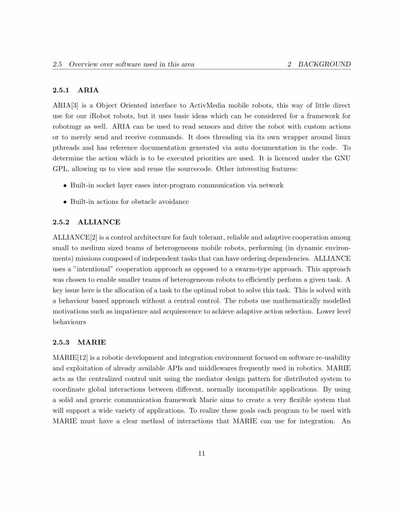
Where this is the section for the CMVision blobfinder algorithm. This driver requires the nameof a camera interface [”camera:0”] and will then provide a blobfinder interface [”blobfinder:0”].The only configuration option is the name of a colorfile which specifies the range of color detectedby the blobfinder and the names and colors associated with those regions.To get those values I used the videoplayer program from the third party software section ofthe PLAYER website. It allows to remotely display the picture the camera is providing atthat moment. I then made a screenshot of this picture using GIMP and changed it to YUVcolors using a plug-in for GIMP. The colours would now seem to be distorted because only thevalues are changed to YUV values of the original colour, but be displayed as RGB values. Theyellow landmark which I chose as a target for the blobfinder was identified easily even in thedistorted colour space and I selected colour values from all over its surface to find a range for
33
5.3 Second Implementation in Java with JADE and PLAYER 5 IMPLEMENTATION
Color Value range for blobY 170-240U 60-90V 130-145
Table 1: Colors and corresponding values in the YUV color space used to configure the CMVisionalgorithm of the blobfinder
the configuration file of the CMVision algorithm. The values I finally decided to take are ones intable 1
Other values that had to be set in the configuration file were constants to translate theabstract distance values reported by the rFlex interface to real distances in mm. Those con-stants were computed by driving the robot along a predefined distance and comparing the re-ported rFlex values with the actual distance. Those three values are connected in this relation:real distance mm = rF lex distance
odo distance conversion . These values are said to be different from robot modelto robot model, so I would have to compute these values again for the ATRV-Mini’s if they needreal distance values. The complete configuration file for the Magellan pro is attached in theappendix C
5.3 Second Implementation in Java with JADE and PLAYER
5.3.1 First steps with PLAYER/STAGE - functionality test
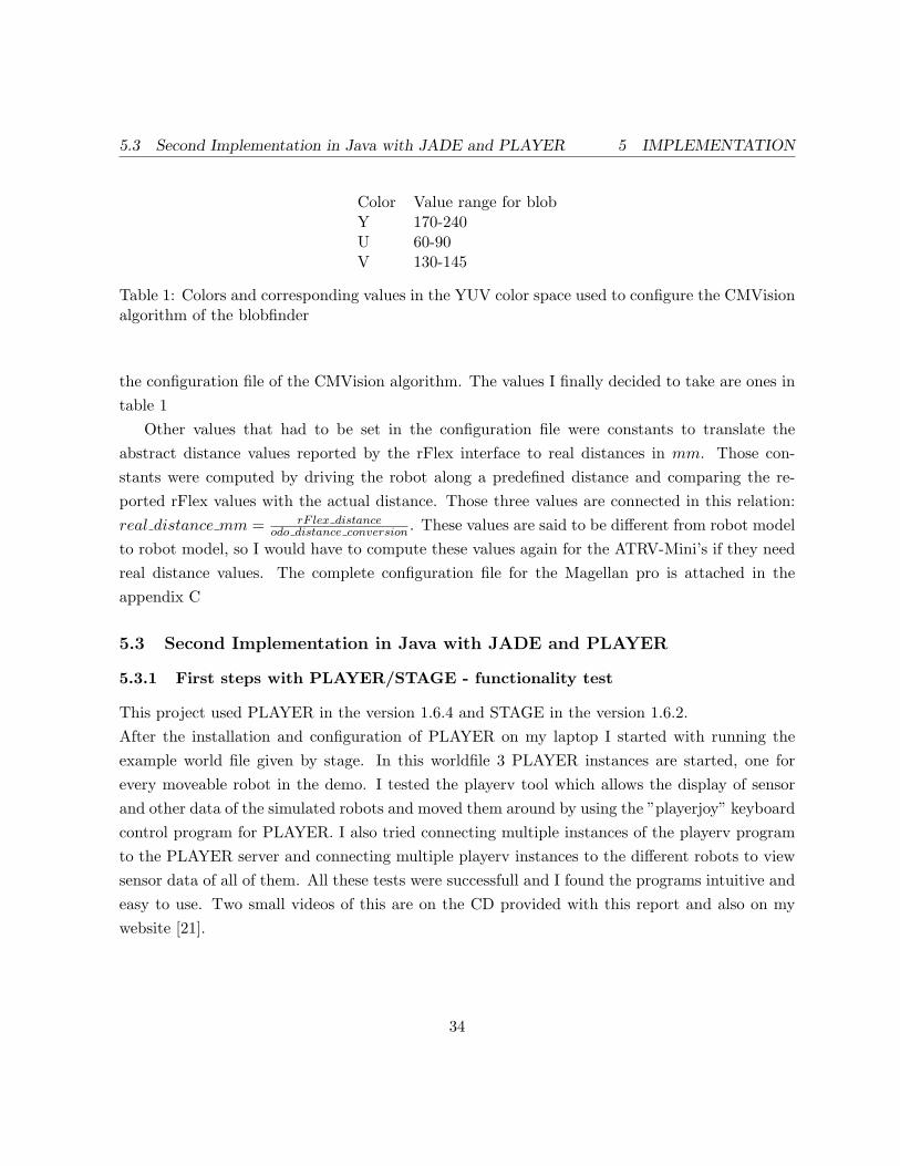
This project used PLAYER in the version 1.6.4 and STAGE in the version 1.6.2.After the installation and configuration of PLAYER on my laptop I started with running theexample world file given by stage. In this worldfile 3 PLAYER instances are started, one forevery moveable robot in the demo. I tested the playerv tool which allows the display of sensorand other data of the simulated robots and moved them around by using the ”playerjoy” keyboardcontrol program for PLAYER. I also tried connecting multiple instances of the playerv programto the PLAYER server and connecting multiple playerv instances to the different robots to viewsensor data of all of them. All these tests were successfull and I found the programs intuitive andeasy to use. Two small videos of this are on the CD provided with this report and also on mywebsite [21].
34

5.3 Second Implementation in Java with JADE and PLAYER 5 IMPLEMENTATION
Figure 8: Example for the blobfinder:(a) Original camera picture, (b) transferred to YUV, (c) with the blob found by the blobfinder
35

5.3 Second Implementation in Java with JADE and PLAYER 5 IMPLEMENTATION
5.3.2 First steps with Java and JADE
I used JADE version 3.3 and the Java RE 5.0.Because my experience in programming in Java was limited I started with looking at the givencode and trying to modify a working example. My biggest problem at that point was the settingof the CLASSPATH variables which determine where the Java classes are to be found on thecomputer -a concept which is quite different to C++ programming. Luckily all necessary toolswere already installed on my laptop so I didn’t have problems to compile Java programs - unlikethe fedora distribution on the robots which caused more problems when setting up the workingenvironment.First steps with JADE were made by testing the PingAgent given in the example code in thedistribution of JADE, this simple agent reacts to a specific kind of message by sending back areply upon receipt. This message is sent by using a so called dummy agent which can be startedin the JADE GUI. It allows to select the type, target and content of a message and to send itafterwards.
5.3.3 First steps with the PLAYER Java-client
The Java client for PLAYER[10] is developed by two persons at the time and not too muchdocumentation is available, the one on the website being a bit outdated. The developers answeredto my requests on the mailing lists and kindly pointed me towards the right use of the clientlibrary. After those initial problems everything was working without further issues. Basically theJava-client is just a very simple interface exchanging messages with the PLAYER server and notmuch can go wrong there. I wrote short test programs in Java to test the position and blobfinderproxy and they worked.
5.3.4 Simple behaviours: Goto, FollowTheLeader
After implementing very small behaviours like Stop which simply stops any ongoing movementat that time I started with implementing the Goto behaviour known from the robotmgr. TheGoto behaviour itself is a tickerBehaviour which is called in a certain frequency as defined inthe program. When created this behaviour saves the target point and with every call of theonTick() function it will compute the angle and distance to the target point. If the angle is belowa certain threshold the robot will move towards the target point, otherwise turn to lower the an-gle to the target. When the distance to the target is also below a certain threshold the robot stops.
36

5.3 Second Implementation in Java with JADE and PLAYER 5 IMPLEMENTATION
The next behaviour to be implemented was called FollowTheLeader. This behaviour is startedby sending an agent a message with the content field containing the following:followtheleader:leader agent namean example would be: followtheleader:player1The receiving agent sends a message to the leader subscribing to its position updates which arethen sent by the leader to every subscribed agent. Upon reception of these position updates therobot executes one step of the goto behaviour to move to a certain new position relative to theposition of the leader.
5.3.5 Simple behaviours: FindBlob
The FindBlob behaviour was implemented in an iterative process because of problems with theunderlying STAGE simulation software. The STAGE software would always report a blob evenif none in sight of the virtual robot, together with garbage values for the blob. After I localisedthis problem I wrote a small workaround ignoring those fake blobs. This was possible becausethe fake blob would have a wrong value set in the windowsize, which provides the size of thecamera picture. On my system the reported false value is always 22648x5, which allowed sortingout those blobs. Another problem with STAGE is that every robot in sight is reported as ablob whereas in the real application only blobs of a certain color are detected. This made someadditional code necessary to use the same code on both the real robot and in STAGE, but intotal those were just 4 lines.On the robot the blobfinder uses the CMVision algorithm[5] which is available as a driver inPLAYER. I configured it as described in section 5.2.3.I used a large landmark so the distance finding algorithm in the behaviour would resturn similarresults on both the real and simulated robot. This distance estimate was then used to tell therobot to come closer if he was to far away or back of if he was to close.If no blob was found in immediate view of the camera the robot would start to turn slowly to theleft until a certain time passes, in which he should turn around 360 degrees in total.If a blob was found the robot turns in order to center the blob in the middle of his view. Thiswill sometimes lead to a longer process of moving until the robot stops in real life because theblobs reported from the CMVision algorithm sometimes change their centre of gravitation due tolight change or something else.
37

5.3 Second Implementation in Java with JADE and PLAYER 5 IMPLEMENTATION
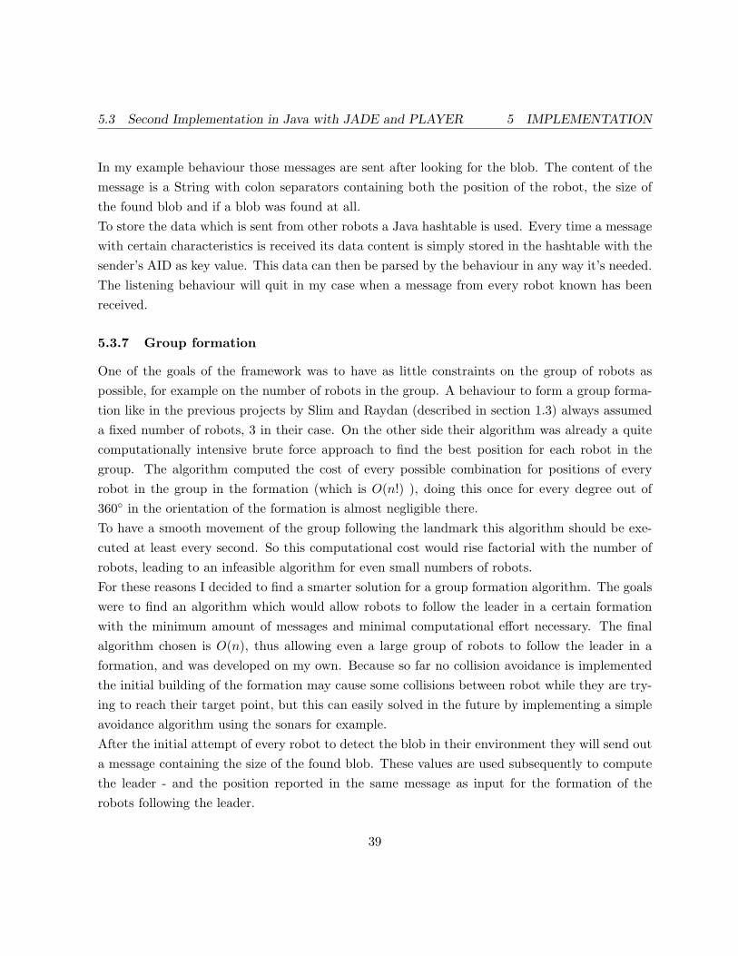
Figure 9: One JADE Platform hosting 3 containers
5.3.6 Coordinating the agents
To coordinate the actions of the group’s robots the approach of domain-independent conventionsas described in section 2.2 was used. Every robot executes the same algorithm with the sameinput values and thus every robot comes to the same plan of actions. This requires either somecommon shared Blackboard on a central server or messages which are sent to every robot.To keep the autonomous character of the robots I chose to have the least centralised services aspossible, thus the solution with sending messages to the robots directly was selected.This still leaves the problem of how to get the other robot’s AIDs in the beginning to sendmessages to them. Past project solved this by using a fixed list - which forced users to use theexact combination of robots every time. To improve this a very low level server is still neededbecause JADE supports no simple broadcast option to send messages to everyone. The JADEsolution to this problem is to connect all the running JADE instances to one platform as describedin [8] and displayed in figure 9. One running JADE instance (in my setup my laptop) hold themain container, all the other JADE instances connect to this platform and use its DF (DirectoryFacilitator). Every agent announces its presence to the DF on startup. Then periodically everyagent queries the DF for the list of known agents, whose AIDs are saved in a data structure.When a message has to be sent to every robot the small SendToAll behaviour I wrote can beused which will cycle through the known agents and add their AIDs are added as targets to themessage before it is sent.
38
5.3 Second Implementation in Java with JADE and PLAYER 5 IMPLEMENTATION
In my example behaviour those messages are sent after looking for the blob. The content of themessage is a String with colon separators containing both the position of the robot, the size ofthe found blob and if a blob was found at all.To store the data which is sent from other robots a Java hashtable is used. Every time a messagewith certain characteristics is received its data content is simply stored in the hashtable with thesender’s AID as key value. This data can then be parsed by the behaviour in any way it’s needed.The listening behaviour will quit in my case when a message from every robot known has beenreceived.
5.3.7 Group formation
One of the goals of the framework was to have as little constraints on the group of robots aspossible, for example on the number of robots in the group. A behaviour to form a group forma-tion like in the previous projects by Slim and Raydan (described in section 1.3) always assumeda fixed number of robots, 3 in their case. On the other side their algorithm was already a quitecomputationally intensive brute force approach to find the best position for each robot in thegroup. The algorithm computed the cost of every possible combination for positions of everyrobot in the group in the formation (which is O(n!) ), doing this once for every degree out of360◦ in the orientation of the formation is almost negligible there.To have a smooth movement of the group following the landmark this algorithm should be exe-cuted at least every second. So this computational cost would rise factorial with the number ofrobots, leading to an infeasible algorithm for even small numbers of robots.For these reasons I decided to find a smarter solution for a group formation algorithm. The goalswere to find an algorithm which would allow robots to follow the leader in a certain formationwith the minimum amount of messages and minimal computational effort necessary. The finalalgorithm chosen is O(n), thus allowing even a large group of robots to follow the leader in aformation, and was developed on my own. Because so far no collision avoidance is implementedthe initial building of the formation may cause some collisions between robot while they are try-ing to reach their target point, but this can easily solved in the future by implementing a simpleavoidance algorithm using the sonars for example.After the initial attempt of every robot to detect the blob in their environment they will send outa message containing the size of the found blob. These values are used subsequently to computethe leader - and the position reported in the same message as input for the formation of therobots following the leader.
39

5.3 Second Implementation in Java with JADE and PLAYER 5 IMPLEMENTATION
Based on those values which are assumed to be all different (in a real application a valid as-sumption) an order of the robots is established by every robot computing its own and for everyother robot the respective distance to the leader, an operation which is O(n). It then saves theAID of the sender of the message with the next bigger distance to the leader than its own - thisrobot is selected as the ”child”, the selecting robot will be called parent from now on. Due to theassumption of mutual exclusive distances to the leader this establishes a common order on everyrobot with exactly one ”child” entry for every robot but the leader which is not the child of anyother robot. The leader is the only robot which is free to move wherever it wants to, but is aparent itself and has a child. The robot furthest away from the leader is a child of another robot,but no parent itself. Once this order is established each robot starts to send out a Follow messageonly to his child, telling it to move to a position in a certain distance behind the position wherethe parent robot is supposed to be. The important part is the word ”supposed”, this meansthat a position change of the leader will result in subsequent fast updates of target positions forevery robot in the group, making it move to the new position much fasten than following onlythe parent would be.
5.3.8 The final complex behaviour
The complex behaviour chosen to demonstrate the proposed architecture is a group following amoving landmark in a certain formation. Its structure is displayed in 10.Several subbehaviours mentioned in the previous subsections are combined together in a finitestate machine behaviour, one of them being a JADE ParallelBehaviour which executes two otherbehaviours in parallel. This will let the robot scan the environment for a landmark and addition-ally listen for new messages from the other robots.Depending on the outcome of the computations in FindClosest either the Lead or Follow sub-behaviour are started. The FSMBehaviour class allows easy changes in the order or additionsof new subbehaviours. The state machine worked immediately after putting the behaviours to-gether, although some testing with simpler dummy state machine were done before to understandthe way they are built in JADE.
40

5.3 Second Implementation in Java with JADE and PLAYER 5 IMPLEMENTATION
Figure 10: Schematic of the finite state machine used in the complex behaviour
41
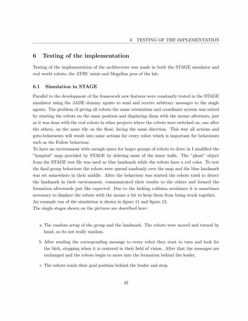
6 TESTING OF THE IMPLEMENTATION
6 Testing of the implementation
Testing of the implementation of the architecture was made in both the STAGE simulator andreal world robots, the ATRV minis and Magellan pros of the lab.
6.1 Simulation in STAGE
Parallel to the development of the framework new features were constantly tested in the STAGEsimulator using the JADE dummy agents to send and receive arbitrary messages to the singleagents. The problem of giving all robots the same orientation and coordinate system was solvedby starting the robots on the same position and displacing them with the mouse afterwars, justas it was done with the real robots in other projects where the robots were switched on, one afterthe others, on the same tile on the floor, facing the same direction. This way all actions andgoto-behaviours will result into same actions for every robot which is important for behaviourssuch as the Follow behaviour.To have an environment with enough space for larger groups of robots to drive in I modified the”hospital” map provided by STAGE by deleting most of the inner walls. The ”ghost” objectfrom the STAGE test file was used as blue landmark while the robots have a red color. To testthe final group behaviour the robots were spread randomly over the map and the blue landmarkwas set somewhere in their middle. After the behaviour was started the robots tried to detectthe landmark in their environment, communicated their results to the others and formed theformation afterwards just like expected. Due to the lacking collision avoidance it is sometimesnecessary to displace the robots with the mouse a bit to keep them from being stuck together.An example run of the simulation is shown in figure 11 and figure 12.The single stages shown on the pictures are described here:
a The random setup of the group and the landmark. The robots were moved and turned byhand, so its not really random.
b After sending the corresponding message to every robot they start to turn and look forthe blob, stopping when it is centered in their field of vision. After that the messages areexchanged and the robots begin to move into the formation behind the leader.
c The robots reach their goal position behind the leader and stop.
42

6.2 Real life testing 6 TESTING OF THE IMPLEMENTATION
Figure 11: Simulation of the complex behaviour: a) random setup of group, b) robots are lookingfor the blob
Figure 12: Simulation of the complex behaviour:c) initial formation, d) landmark is moved, robotsmove to new position, d) robots stay in new position
d The landmark is moved and the robots start to move into their positions in the formationbehind the now turned leader.
e The robots reach their position in the formation again.
The boxes which can be sometimes seen next to the robots are the visualisation of the blobfinderdata in stage.
6.2 Real life testing
The first test of the Goto behaviour on a real robot - The Magellan pro I used for testing - resultedin it turning around for a while when it was only supposed to turn 20 degrees. I realized that the
43

6.2 Real life testing 6 TESTING OF THE IMPLEMENTATION
configuration file, especially the odo distance conversion values had to be set first, additionallyI implemented a security check in the PlayerAgent to prevent the robot from ever moving fasterthan a predefined limit.Other problems in real world testing were due to the limited space in the lab, extra care had tobe taken with combined simulation/real world testing using STAGE in which the virtual robotwould lead the real robot.The FollowTheLeader behaviour was working just like in the simulator, no further changes had tobe done. A problem with a mixed set of robots was again the difference in the odo distance conversion
values which resulted in growing discrepancies between the two world views of of the leader andthe follower in a two robot case with min1 and mag3 for example. Even worse are the differencesin measuring the angles of the robots. Because the ATRV minis are using a four wheel poweredapproach for turning the odometry data is quite inaccurate. Tests where I let the min1 robotturn for 90 degrees and then turn 90 degrees in the other direction would result into an offsetof approximately 10 degrees between the old world frame of the robot - thus giving a huge errorafter some movements which include turns. The Magellan Pro robots don’t have these problemsin this scale as their two wheeled method of turning is far less susceptible to inaccuracy.This issue is discussed extensively in literature, and there are error models to describe it, forexample in [19, pp.186]. Basically some advanced localization attempts have to be made if theodometry data is of only poor quality. PLAYER includes some virtual devices for this task suchas the Advanced Monte-Carlo-Localization, but these often require sensors like a SICK laserscanner. This problem, described as ”one of the most pervasive perception problems in robotics”[16, p.908], will not be considered further in this report and is a good recommendation for futurework as stated in section 8.The next behaviour tested was the FindBlob behaviour. As I knew from monitoring the resultsfrom the blobfinder interface of the real robot the real blobfinder detects a lot more than justone blob even if centered directly on the landmark. Most of the unwanted blobs are in the areaof the wanted one but incur due to the used CMVision algorithm. These values were ignored inthe FindBlob behaviour by sorting the blobs reported by the interface and only looking at thebiggest ones. Also small blobs below a certain size can be safely ignored as they can result froma noisy camera picture. After some filtering has been done on the reported blob the coordinatesof the largest blob’s center of gravity are then used to give the robot commands to center thecamera on this blob. This was tested initially by just giving out the commands the behaviourwould give on the commandline, after those were confirmed to be right the move commands were
44

6.2 Real life testing 6 TESTING OF THE IMPLEMENTATION
Distance Size of largest blob≤10 cm 50,000100cm 5000≥200cm 1000
Table 2: Listing of distances of the landmark and the corresponding amount of pixels reportedby the blobfinder interface
given to the robot. Because the size of the real camera picture is bigger than the simulated one Ialso had to change the FindBlob algorithm a bit to give a blobsize relative to the camera windowsize.
While testing the blobfinder trained to recognise the two-colored large soccer field poles inthe lab I found the values displayed in table 2 for the Area of the main blob.Other problems in real world testing were due to the limited space in the lab, extra care had to
be taken with combined simulation/real world testing using STAGE in which the virtual robotwould lead the real robot.
45

7 TIMELINE
7 Timeline
7.1 Comment on the original schedule
The original schedule was based on the assumption that the software setup in the lab would besufficient to use it in the project, and no major switches to other software should be necessary.During the initial research and test phase of the project this assumption turned out to be invalid,as the Software basis used by the formed smaller projects, C++ and robotmgr didn’t provide anyframework like means to simplify the handling of messages between the robots. As communicationbetween the robots via messages is a basic requirement for an autonomous mobile robot systemthis made the development of the C++ siftware unnecessarily complicated and required a lotof work for non research topic area programming of message handling and multi-threading forexample. The weak documentation and the fact that the only programmer of the robotmgrsoftware was about to finish his master’s thesis didn’t help with those programs either, as Icouldn’t get important message handling features in robotMgr to work in my test programs.After extending my research on multi-agent frameworks for other programming languages thanC++ and talking to people using the robots for bigger projects such as Bram, I decided totry JADE as the framework for inter-robot communication. My discovery of PLAYER and theSTAGE simulator, also including a JAVA client software to control the PLAYER server forcedme to rethink the original timeline in the third week. I started switching completely to PLAYER,which also required a newer LINUX version on the robots. The test robot was ready for use inweek 6 which allowed my to start on the actual work on the framework. At this point the originalschedule was already assuming the work on the second objective, the cooperative box pushing,which obviously couldn’t be done at that point due to the above reasons.
7.2 Revised timeline
The weekly reports I wrote are available in the Appendix A. Here follows a very short summaryfor them:
• First week (May 9.-14.):Introduction to the lab, the people working there and the software. Organising keys andaccounts for the computer network. Searching papers and books which cover the projectstopics.
• Second week(May 17.-20.):
46
7.2 Revised timeline 7 TIMELINE
Planning of the research topics. Modification of existing software to let a group of robotschoose the one nearest to a landmark, this one now follows the landmark if it is moved.Extensive review of the old code.
• Third and Fourth week (May 23.-June 3.):Using the experience gained from reading and modifying the old code, the work the frame-work was started after evaluating different possible solutions the best method known tothat time was selected. The framework was tested with some basic behaviours like collisionavoidance and collision detection.After the discovery of PLAYER the switch to this platform was considered and PLAY-ER/STAGE was tested locally on my computer.
• Fifth and Sixth week (June 6.-June 17.):Unsuccessful attempts to extend the preexisting communication network in C++ in theFifth week, the Sixth week was spent on updating the OS on the ATRV mini.
• Seventh and Eight week (June 20.-July 1.):In the Seventh week I explored the possibilities of PLAYER on the real robot and prepareda talk on PLAYER which I held for the focus group on Friday. The Eight week was spentwith looking into JADE which I had discovered on the previous weekend.
• Ninth and Tenth week (July 4.-July 15.):After having finally decided on JADE and PLAYER as the basis for the architecture Istarted implementing it and some basic behaviours during those two weeks. I would testnew behaviours in the STAGE simulator first and try them on the real robots later.
• Eleventh, Twelfth and Thirteenth week (July 18.-August 10.):The complex FSM behaviour was finished in the Eleventh week, the two following weekswere mostly spent with compiling the report and writing additional documentation for usersof my framework.
47
8 RECOMMENDATIONS AND FUTURE WORK
8 Recommendations and future work
8.1 JADE
Even though I haven’t used Java for more than small assignments in undergrad classes I had noproblems with using it together with JADE. There is excellent documentation on JADE and Ifound the concepts very easy to understand and use. I would advise anyone who wants to startfuture work on group behaviour to use JADE instead of writing own implementations of messagehandling routines. Using Jade I was able to program basic behaviours which took other groupsweeks in days only - of course being able to simulate the robots in STAGE helped a lot, too.
8.2 JESS
Because Jade lacks own functions for machine intelligence it would benefit from combining it witha machine intelligence software like JESS. This has be done at other places such as in [9]
8.3 Further use of PLAYER drivers
Now that Ben Miners is finished with his master’s thesis future programmers using robotMgras the base for their programs will most probably have to debug possible bugs in robotMgrby themselves, also Ben won’t be able to introduce them to the basics of robotmgr. AlthoughrobotMgr is indeed a good program and successfully used in many applications in the PAMI labso far in my opinion PLAYER is the better choice for future work with the robots. The Javaclient for PLAYER worked flawlessly for me, the whole project is developed and successfully usedon more than 30 universities all around the world which shows its popularity. In my project Ihaven’t even used the more advanced interfaces provided by PLAYER such as self-localization,map building, way planning and so forth. Each one of those features make a good project toexplore alone, and show the superiority of a global developers community. The fact that PLAYERalso supports different platforms than just rFlex alone is also important now that iRobot stoppedproducing civil robots other than pink autonomous brooms. Programs written for PLAYER canbe used with only little extra effort on robots based on a different hardware platform but similarsensors. The simulation engines STAGE and GAZEBO offer also a big advantage compared torobotmgr, as they allow quick debugging and fast prototyping without having to fear to damagethe real robots due to programming errors when they suddenly run wild.
48
8.4 Enhancements for PLAYER 8 RECOMMENDATIONS AND FUTURE WORK
8.4 Enhancements for PLAYER
The modular concept allows easy extension with own drivers, which could be the artificial land-mark detection from the old project for example, using the blobfinder interface and basing onthe CMVision driver which does indeed a quite similar task. So far such a landmark recognitiondriver is not available for player and this would be a suitable contribution from the PAMI labto the PLAYER community. Instead of returning colored squares for detected colors from thecamera this algorithm could return those square if an artificial landmark was detected.
49

9 CONCLUSIONS
9 Conclusions
Starting with analysing and extending previous projects I decided that a more general frameworkfor robot behaviour and communication would be necessary to avoid spending most effort on thebasic tasks every time a new project begins.Research done on open source software used in this area brought some examples which werecompared and two of them were selected to be combined to use in the future framework.The robot’s 3 year old operating system had to be upgraded to be able to support recent versionsof the selected software and to ease future updates of the the OS a free distribution called Fedorawas chosen.The new software, PLAYER and JADE was installed on the robots, tested and configured. Afterit was considered suitable it was also installed on the other robots.To demonstrate the effectiveness of the selected software combination a cooperative group be-haviour was written. It is based on ideas of projects done by previous group but required acomplete rewrite from scratch due to the different software used. The group behaviour is com-posed out of multiple smaller subbehaviours connected by more complex JADE behaviours toa finite state machine running autonomously on an own JADE instance on every robot in thegroup. Using the advanced interfaces of PLAYER these behaviours themselves are simple andeasy to exchange. JADE provides flexible ways to connect those subbehaviours and providessimple means to communicate with other robots in the group, exchange data such as positionswith them or make remote behaviour calls.To develop these subbehaviours and the final complex behaviour the STAGE simulator was usedto test the algorithms. When those algorithms would work reliably they could be tested withoutmodifications on the robots which helped to speed up the development.The final behaviour was then successfully tested in a mixed simulated/real world environmentwhere both simulated and real robots follow an existing landmark moved by a user.
50

REFERENCES
10 References
References
[1] AgeS: Filling a Gap between Single and Multiple Agent Systems, James Kramer andMatthias Scheutz, Dep. of Comp.Sci. and Engineering, University of Notre Dame, IN.
[2] L. E. Parker. ALLIANCE: An architecture for fault-tolerant multi-robot cooperation. IEEETransactions on Robotics and Automation, 14(2):220–240, 1998.
[3] ARIA is a Object Oriented interface to ActivMedia mobile robots.http://www.activrobots.com/SOFTWARE/aria.html
[4] Reliable Mobile Robot Navigation From Unreliable Visual CuesIn Fourth International Workshop on Algorithmic Foundations of Robotics (WAFR 2000),Hanover, NH
[5] CMVision algorithmhttp://www-2.cs.cmu.edu/ jbruce/cmvision/ ,2005
[6] Festival softwarehttp://www.cstr.ed.ac.uk/projects/festival/download.html ,2005
[7] Java Agent DEvelopment framework http://jade.tilab.com/
[8] JADE Tutorial, JADE programming for beginners, Giovanni Caire,http://jade.cselt.it/doc/programmersguide.pdf
[9] Advanced uses of JADE http://jade.tilab.com/community-3rdpartysw.htm
[10] Java client for PLAYER http://java-player.sourceforge.net/
[11] The MAGE robot control softwarehttp://robotics.swarthmore.edu/downloads.shtml
[12] Ct, C., Ltourneau, D., Michaud, F., Valin, J.-M., Brosseau, Y., Raevsky, C., Lemay, M.,Tran, V., ”Code Reusability Tools for Programming Mobile Robots”, accepted for presenta-tion to IROS2004. http://marie.sourceforge.net/
51
REFERENCES REFERENCES
[13] Mobility Robot Integration Software Manual
[14] The Pattern Analysis and Machine Intelligence (PAMI) research group at the university ofWaterloopami.uwaterloo.ca
[15] The Player/Stage Project: Tools for Multi-Robot and Distributed Sensor Systems. Proceed-ings of the International Conference on Advanced Robotics (ICAR 2003),pages 317-323
[16] Stuart Russel,Peter Norvig. Artificial Intelligence - A Modern Approach.Pearson Educationinc,Upper Saddle River,New Jersey,2003
[17] Andrea Schaerf, Yoav Shoham, and Moshe Tennenholtz. Adaptive load balancing: A studyin multi-agent learning. Journal of Artificial Intelligence Research, 2:475-500, 1995.
[18] SFERES: Artificial evolution framework together with a multi-agent framework.http://sferes.lip6.fr/external/about.php ,2005
[19] Roland Siegwart, Illah R. Nourbakhsh, Introduction to Autonomous Mobile Robots, MITPress, 2004
[20] Eiji Uchibe, Minoru Asada, and Koh Hosoda. Behavior coordination for a mobile robotusing modular reinforcement learning. In Proc. of IEEE/RSJ International Conference onIntelligent Robots and Systems 1996 (IROS ’96), pages 1329-1336, 1996.
[21] Homepage with material of this project http://www.eng.uwaterloo.ca/∼notippen/ ,2005
52

A WEEKLY SUMMARY
11 Appendix
All material will also be available on the CD which you should have received together with thiscopy of my report. If you need another copy of the CD please write an email to [email protected]
A Weekly summary
A.1 First week
The first week started with Mohammed showing me the now working implementation of theformation building by mazen and mackram on Monday. I also tried to get the necessary keysat the offices in EIT. The next days were spent in reading basic books on the topic and readingbasic papers which were provided by professor Kamel. The books included the following:
• Mobile Robotics. A practical Introduction. Ulrich Nehmzow. Springer,Berlin, 2003
• Introduction to autonomous mobile robots. Roland Siegwart and Illah R. Nourbakhsh.
• Minimalist mobile robotics : a colony-style architecture for an artificial creature. JonathanH. Connell.
I also collected the source code for the old projects by Mazen and Mackram and the other projectswhich were done before that. Until the end of the week I had the required keys to access theinternal room with the robots. After I found out whom to ask about an account for the computersI requested an account.
A.2 Second week
In the beginning of the week I continued with reading the background informations from thebooks, in parallel I started to modify the existing code. One example is a small task to stop therobot on bumper contact which I wrote. I got the Windows network account to access the PCsin the lab.Due to the specialised programming of the legacy programs I has difficulties in extending themto new tasks with reprogramming a considerable part. Those older programs were also mostlyprogrammed for an older version of robotmgr so I had to do some bug fixing to even compilethem to start with. Unfortunately my laptops’s harddisk died the previous Friday, so I also hadto spend considerable time on reinstalling the laptop’s operating system, old backups and settingup a productive environment. Some written work done in the previous week was lost because Ididn’t make a backup of it.
53

A.3 Third week A WEEKLY SUMMARY
A.3 Third week
During the week I set up printing with my Linux laptop (had trouble with printing from theWindows PCs).Tue-Thu: Started to work on the construction of the framework for flexible behaviours with dif-ferent triggers, including efforts to understand the old code by Mazen and mackramFri-Sun: Mostly research on existing open-source software suitable to use with our robots. Thisshould considerably lower the effort to get a stable base for future developments in the PAMI lab.I also got CVS access to the robotmgr tree in this week.
Plans for the Behaviour framework so far:
• All robots run a server app, at the moment thats vidcap.cpp. This server starts basic stufflike message listening etc. This server also handles incoming messages and searches themfor commands etc. The server will start behaviours modules depending on the receivedcommands, and enables the behaviour modules to communicate to the other robots.The server will also allow other robots to access all data that this robot has gathered, suchas position, angles of both robot and his PTZ unit and data on the landmark etc.
• The command.cpp will allow the user to enter commands at one robot. The commandwill then be spread to all robots by the command.cpp. Apart from one robot sunningcommand.cpp and spreading the messages, all robots are behaving totally equally.
• The behaviour modules implement different behaviours for the robots. These include theported versions of the behaviours Mazen and mackram wrote, this time more cooperative.In the original version the code by Mazen and mackram just lets the two robots which don’trun the command.cpp report their position, with which the ”master robot” then computestheir position in the formation and sends it to them.Some modules that are planned are:
– Line - The ”line behaviour” from Mazen and Mackram ported to fit the framework,more cooperative
– triangle - The ”triangle behaviour” from Mazen and Mackram ported to fit the frame-work
– vidcap - The ”vidcap behaviour” from Ben ported to fit the framework. The robotwon’t follow the landmark unless it is the selected ”leader” in the group (local variableof the robot object). But it will try to find and follow it with the PTZ cam unit. Onceit either found the landmark or finished the 360 degree scan it will send a message tothe other robots to report its success or failure in finding the pattern. It will then waitfor the other messages to arrive and then determine the leader, every robot does this
54

A.4 Fourth week A WEEKLY SUMMARY
on its own. The robot selected as leader will then send a message to the others tellingthem the formation they should take (could be based on a barcode in the landmark).Optional, might be implemented later:The other robots continue to look for the landmark. They continue to send messages ifthey see it, if they are now closer than the leader the leadership changes to the closestrobot.
– line follow - The behaviour to follow the leader in a line formation. The two robotscommunicate their positions to each other and then look for the global best solutionfor their position, to which they move then.
– triangle follow - The behaviour to follow the leader in a triangle formation
A.4 Fourth week
After discovering PLAYER/STAGE last week I compiled it, which took some time because ofsome smaller compilation issues. I looked for example applications of PLAYER/STAGE andfound one at the project MARIE. First tries with PLAYER/STAGE on my laptop were workingfine and looked promising. The player project still lacks a control and communication structurefor group behaviour, so I continued to look for other software to take over those parts.On my search for open source software to use on the robots I found other software as well, so Imade a short summary of those programs in a separate paper, although I didn’t find a softwareto take over the group communication part.I tried to compile the PLAYER server locally in my home directory on one of the magellans(mag2) but the software (e.g. GCC) on the robots is far too old. I discussed with Ben to install anewer version of Linux on the robots and spend some time looking for a decent possibility to getthe robot to boot from an installation medium, but found none so far. As the robots don’t havea floppy, CD-ROM or other flexible installation drive we might need to use the /home partition(which has 22GB) as the partition for the installation. Another possibility would be to exchangethe whole harddisk against another one/connect the harddisk in the robot to a normal PC tobuild the new linux on this one. The install procedure is described in the mobility handbook inthe appendix A-2. The information needed to connect a serial console to the robot’s PC is givenin the robot’s handbook (9600 8N1).
A.5 Fifth week
This week began with working on the reimplementation of the framework. The basis was againthe second project from Mazen Slim and Mackram Raydan, which was cleared of any code notfitting to the concept of the framework. At the end the basic message sending and receiving andthe robot class were the only code fragment kept for the new project. Then the first version of theframework was written, it had some simplifications at some points to allow a faster testing. Themessage passing between the robots from the old code turned out to be a bit more complicated
55
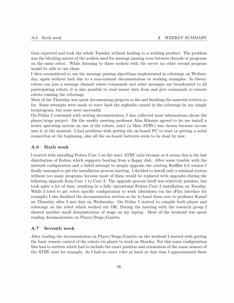
A.6 Sixth week A WEEKLY SUMMARY
than expected and took the whole Tuesday without leading to a working product. The problemwas the blocking nature of the sockets used for message passing even between threads or programson the same robot. While listening to those sockets with the server no other second programwould be able to use these.I then reconsidered to use the message passing algorithms implemented in robotmgr on Wednes-day, again without luck due to a non-existant documentation or working examples. In theoryrobots can join a message channel where commands and other messages are broadcasted to allparticipating robots, it is also possible to read sensor data from and give commands to remoterobots running the robotmgr.Most of the Thursday was spent documenting progress so far and finishing the material written sofar. Some attempts were made to trace back the segfaults caused in the robotmgr by my simpletestprogram, but none were successful.On Friday I continued with writing documentation, I also collected more informations about theplayer/stage project. On the weekly meeting professor Alaa Khamis agreed to let me install anewer operating system on one of the robots, min1 (a Mini ATRV) was chosen because no-oneuses it at the moment. I had problems with getting the on-board PC to start or getting a serialconnection at the beginning, also all the on-board batteries seem to be dead by now.
A.6 Sixth week
I started with installing Fedora Core 1 on the min1 ATRV mini because as it seems this is the lastdistribution of Fedora which supports booting from a floppy disk. After some trouble with thenetwork configuration and a failed attempt to simply upgrade the existing RedHat 6.2 version Ifinally managed to get the installation process starting. I decided to install only a minimal systemwithout too many programs because most of them would be replaced with upgrades during thefollowing upgrade from Core 1 to Core 3. The upgrade process itself was relatively painless, buttook quite a lot of time, resulting in a fully operational Fedora Core 3 installation on Tuesday.While I tried to get robot specific configuration to work (shutdown via the rFlex interface forexample) I also finalized the documentation written so far to hand them over to professor Kamelon Thursday after I met him on Wednesday. On Friday I started to compile both player androbotmgr on the robot which worked out OK. During the meeting with the research group Ishowed another small demonstration of stage on my laptop. Most of the weekend was spentreading documentation on Player/Stage/Gazebo.
A.7 Seventh week
After reading the documentation on Player/Stage/Gazebo on the weekend I started with gettingthe basic remote control of the robots via player to work on Monday. For this some configurationfiles had to written which had to include the exact position and orientation of the sonar sensors ofthe ATRV mini for example. As I had no exact ruler at hand at that time I approximated these
56

A.8 Eighth week A WEEKLY SUMMARY
values for a start, the angles should be correct though. The whole process took some time be-cause I found no documentation about how to write those configuration files apart from workingexamples given on the webpages. I also modified the stage configuration files to use a model of theATRV mini in the simulation. I tried one of the example control codes called sonarobstactleavoidon the real robot in a court set up in the lab and it worked.Tuesday I spent quite some time to get the camera to work, some issues with the video4linux2driver and most importantly a probably defective black and white camera delayed this processto take a whole day.Wednesday I took one of the Sony PTZ cameras from mag3 to try the PTZ control in Player.The control works now, but there seems to be a small problem with the serial connection fromthe camera to ttyS2 - sometimes it is necessary to replug the connection because it won’t workotherwise.Most of the Thursday was spent writing a small introduction to Player/Stage/Gazebo and cap-turing short movies to use during the presentation. The work on the presentation continued untilFriday, when the presentation was held.As final element of the robot which needed testing I tried the speech synthesys with Festival,supported by Player. This would test both the physical audio output hardware which was, to myknowledge, never used before, as also the ALSA Linux sound driver and the Festival program,of course. After finding and connecting a set of speakers to the right port in the robot, speechoutput worked right away, so I could assume the Linux install on min1 to be fully successfull.The only remaining problem is more a minor annoyance: When shutting down the robot via therFlex interface the rFlex controller waits for the words:”The system is halted” on the console andthen kills the power to the system. It seems that with the software installed on min1 these wordschanged to ”System halted”, which prevents the rFLex device from shutting down power fromitself.
A.8 Eighth week
After a presentation of Bram about his project with the Magellans and a following discussion Idecided to have another look at using CORBA for Inter robot communication. I read before thatone of the earlier groups with Fan,Wong and Yuen planned to use CORBA but then dropped thisplan because it was too complicated for them - even though they were a group of 3 and they had6 months of time during their project. This was the reason I ignored Corba at the beginning.Bram used the JADE Java Agent DEvelopment Framework which indeed looks quite powerfull,for example it already provides almost everything I mentioned as design ideas for the framework Iproposed in my initial project proposal. The downside is that it uses Java in which I have mostlyonly theoretical knowledge. So I spent the weekend and Monday on reading on Jade and Corbain general, also looking for a possible C++ equivalent.On Tuesday I started looking at the code Bram wrote for his project. He used robotmgr, of course- so one possibility for work of me could be porting the existing code to use Player as software to
57
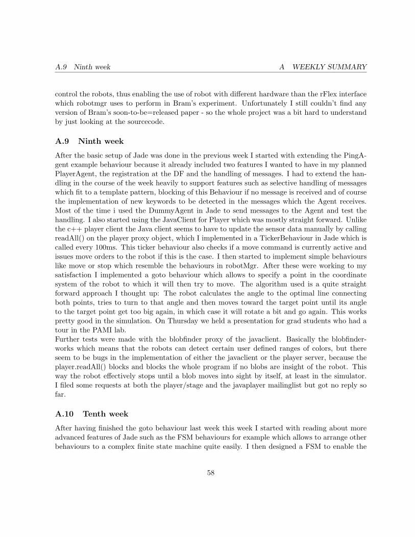
A.9 Ninth week A WEEKLY SUMMARY
control the robots, thus enabling the use of robot with different hardware than the rFlex interfacewhich robotmgr uses to perform in Bram’s experiment. Unfortunately I still couldn’t find anyversion of Bram’s soon-to-be=released paper - so the whole project was a bit hard to understandby just looking at the sourcecode.
A.9 Ninth week
After the basic setup of Jade was done in the previous week I started with extending the PingA-gent example behaviour because it already included two features I wanted to have in my plannedPlayerAgent, the registration at the DF and the handling of messages. I had to extend the han-dling in the course of the week heavily to support features such as selective handling of messageswhich fit to a template pattern, blocking of this Behaviour if no message is received and of coursethe implementation of new keywords to be detected in the messages which the Agent receives.Most of the time i used the DummyAgent in Jade to send messages to the Agent and test thehandling. I also started using the JavaClient for Player which was mostly straight forward. Unlikethe c++ player client the Java client seems to have to update the sensor data manually by callingreadAll() on the player proxy object, which I implemented in a TickerBehaviour in Jade which iscalled every 100ms. This ticker behaviour also checks if a move command is currently active andissues move orders to the robot if this is the case. I then started to implement simple behaviourslike move or stop which resemble the behaviours in robotMgr. After these were working to mysatisfaction I implemented a goto behaviour which allows to specify a point in the coordinatesystem of the robot to which it will then try to move. The algorithm used is a quite straightforward approach I thought up: The robot calculates the angle to the optimal line connectingboth points, tries to turn to that angle and then moves toward the target point until its angleto the target point get too big again, in which case it will rotate a bit and go again. This workspretty good in the simulation. On Thursday we held a presentation for grad students who had atour in the PAMI lab.Further tests were made with the blobfinder proxy of the javaclient. Basically the blobfinder-works which means that the robots can detect certain user defined ranges of colors, but thereseem to be bugs in the implementation of either the javaclient or the player server, because theplayer.readAll() blocks and blocks the whole program if no blobs are insight of the robot. Thisway the robot effectively stops until a blob moves into sight by itself, at least in the simulator.I filed some requests at both the player/stage and the javaplayer mailinglist but got no reply sofar.
A.10 Tenth week
After having finished the goto behaviour last week this week I started with reading about moreadvanced features of Jade such as the FSM behaviours for example which allows to arrange otherbehaviours to a complex finite state machine quite easily. I then designed a FSM to enable the
58

A.11 Eleventh week A WEEKLY SUMMARY
robots to try to detect a blob, send messages to all other active agents about it and collecttheir replies. To keep track of other agents in the network I used a central name service towhich every client connects upon it’s start. The agents register to that service upon startupand query it every 10 seconds or so to update their internal database with this data. Whenthe agent wants to send a message to every other agent he calls the SendToAll behaviour whichuses the database of the known clients and sends the message to everyone. Another behaviourcalled WaitForAllMsg waits for a certain message to come from every known robot. Once bothbehaviours have finished successfully the FSM will activate the next behaviour, in which theinstances in the received messages are compared and the closest robot is selected. This is doneon every robot individually, but since every robot has the same data this will lead to the sameresults for everyone. The closest robot is made the leader, every other robot will start the Followbehaviour while the leader starts the LEAD behaviour. These behaviours are again started bythe FSM according to the return value of the CopmuteClosest behaviour, which will return ’0’in case the robot will follow or ’1’ if its the leader. To manipulate the return value of behavioursthe onEnd() method has to be overridden, the return value of this function is the value used bythe FSM.
A.11 Eleventh week
The eleventh week started with continued work on the FSM behaviour. The problem with theblobfinder giving false values in the simulator was finally not resolved but I found a workaround- because falsely reported blob have always the same size they can be sorted out easily. Anotherproblem is that the blobfinder in stage will report any colored blobs, so I have to sort out theunwanted red blobs from the robots as well.
A.12 Twelfth week
With the FSM behaviour working I started to finish the report so not too much exiting can besaid about this week. I met Prof. Kamel and we agreed on me having a presentation on Fridaythe 9th - so I will have to prepare that one too. I plan to give a live presentation of the behaviourwith both classes of robots and also the simulated ones - that’s going to be interesting! I fixedthe design of this report using templates provided on the waterloo website. It uses font size 11,line spacing of 1.2 and custom borders which all looks perfect to me. Additionally I decided touse the fancy style to get the page headers which I find quite helpful. The graphics for the reportare almost done, I’m still undecided if I should prefer black and white or color ones... will haveto decide on that soon.
A.13 Thirteenth week
With only 3 remaining days this week was quite short... I finished the report by typing this andare going to proofread it later.
59

B USER GUIDE TO PLAYER/JADE ROBOTIC ARCHITECTURE
B User guide to PLAYER/JADE robotic architecture
I wrote a user’s guide to my project with practical hints on running and operating the project’sdemonstration. It is handed in separate print for greater convenience while using it. It is alsoavailable on the CD as a PDF file called Userguide.pdf.
60

C PLAYER/STAGE CONFIGURATION FILES
C PLAYER/Stage configuration files
This is the configuration file of the ATRV mini called ”rflex.atrv”. The configuration file for theMagellan pro (”rflex.magellan”) has additional sections for the IR devices. Both configurationfiles are also on the CD.
driver(
name "camerav4l"provides ["camera:0"]size [320 240]source 1save 0 #this would create screendumps - and generate big amounts of data fast!norm "ntsc"
)driver(
name "cameracompress"provides ["camera:1"]requires ["camera:0"] # Compress data from device camera:0save 0 #this would create screendumps - and generate big amounts of datra fast!
)driver(
name "cmvision"provides ["blobfinder:0"]requires ["camera:0"]colorfile "color.cfg"
)# This stuff doesn’t really work so far but is interesting#driver#(# name "festival"# provides ["speech:0"]#)
#driver#(# name "sphinx2"# provides ["speech_recognition:0"]
61

C PLAYER/STAGE CONFIGURATION FILES
#)
driver(
name "sonyevid30"provides ["ptz:0"]port "/dev/ttyS2"fov [3 30]
)
driver(
name "rflex"provides ["position:0" "sonar::sonar:0" "sonar2::sonar:1" "power:0" ]
rflex_serial_port "/dev/ttyS1"mm_length 500.0mm_width 300.0odo_distance_conversion 190odo_angle_conversion 60000default_trans_acceleration 50.0default_rot_acceleration 1.0rflex_joystick 1rflex_joy_pos_ratio 6rflex_joy_ang_ratio -0.01range_distance_conversion 1.476sonar_age 1sonar_echo_delay 30000sonar_ping_delay 0sonar_set_delay 0max_num_sonars 224num_sonars 16num_sonar_banks 2num_sonars_possible_per_bank 16num_sonars_in_bank [8 8]# theta (rads), x, y (mm) in robot coordinates (x is forward)mmrad_sonar_poses [
0.00000 200.00000 100.000000.31416 180.00000 110.000000.62832 160.00000 130.00000
62

C PLAYER/STAGE CONFIGURATION FILES
0.94248 140.00000 140.000001.25664 120.00000 150.000001.57079 100.00000 150.000001.57079 -200.00000 150.000003.14159 -200.00000 150.000000.00000 200.00000 -100.00000-0.31416 180.00000 -110.00000-0.62832 160.00000 -130.00000-0.94248 140.00000 -140.00000-1.25664 120.00000 -150.00000-1.57079 100.00000 -150.00000-1.57079 -200.00000 -150.00000-3.14159 -200.00000 -150.00000]
sonar_2nd_bank_start 8
rflex_power_offset 12)
63

D JADE PLAYERAGENT CODE
D Jade PlayerAgent Code
The main source code of this project is in the PlayerAgent.java file on the CD in the source codedirectory. In total it is about 1000 lines long - 25 pages, that’s why I didn’t include it in printhere.
64