a multi point fuel injection
TRANSCRIPT
13A-1
GROUP 13A
CONTENTS
GENERAL INFORMATION . . . . . . . . 13A-2
CONTROL SYSTEM . . . . . . . . . . . . . 13A-7
SENSOR. . . . . . . . . . . . . . . . . . . . . . . 13A-8
ACTUATOR . . . . . . . . . . . . . . . . . . . . 13A-14
FUEL INJECTION CONTROL . . . . . . 13A-15
THROTTLE VALVE OPENING ANGLE CONTROL . . . . . . . . . . . . . . . . . . . . . 13A-23
IGNITION TIMING AND DISTRIBUTION CONTROL . . . . . . . . . . . . . . . . . . . . . 13A-25
MIVEC (Mitsubishi Innovative Valve timing Electronic Control system) . . . . . . . 13A-31
POWER SUPPLY CONTROL. . . . . . . 13A-39
FUEL PUMP RELAY CONTROL . . . . 13A-40
OXYGEN SENSOR HEATER CONTROL . . . . . . . . . . . . . . . . . . . . . . . . . . . . . . . . . . . . . . . . . . . . . . . . . . . . . . . . . . . . . . . . . . . . . . . . . . . . . . . . . . . . . . . . . . . . . . . . . . . . . . . . . . . . . . . . . . . . . . . . . . . . . . . . . . . . 13A-41
A/C COMPRESSOR CONTROL. . . . . 13A-42
ALTERNATOR CONTROL . . . . . . . . . 13A-43
STARTER RELAY CONTROL . . . . . . 13A-44
CONTROLLER AREA NETWORK (CAN) . . . . . . . . . . . . . . . . . . . . . . . . . . . . . . . . . . . . . . . . . . . . . . . . . . . . . . . . . . . . . . . . . . . . . . . . . . . . . . . . . . . . . . . . . . . . . . . . . . . . . . . . . . . . . . . . . . . . . . . . . . . . . . . . . . . . 13A-44
DIAGNOSIS SYSTEM. . . . . . . . . . . . . 13A-45
GENERAL INFORMATIONMULTIPOINT FUEL INJECTION (MPI)13A-2
GENERAL INFORMATIONM2132000100428
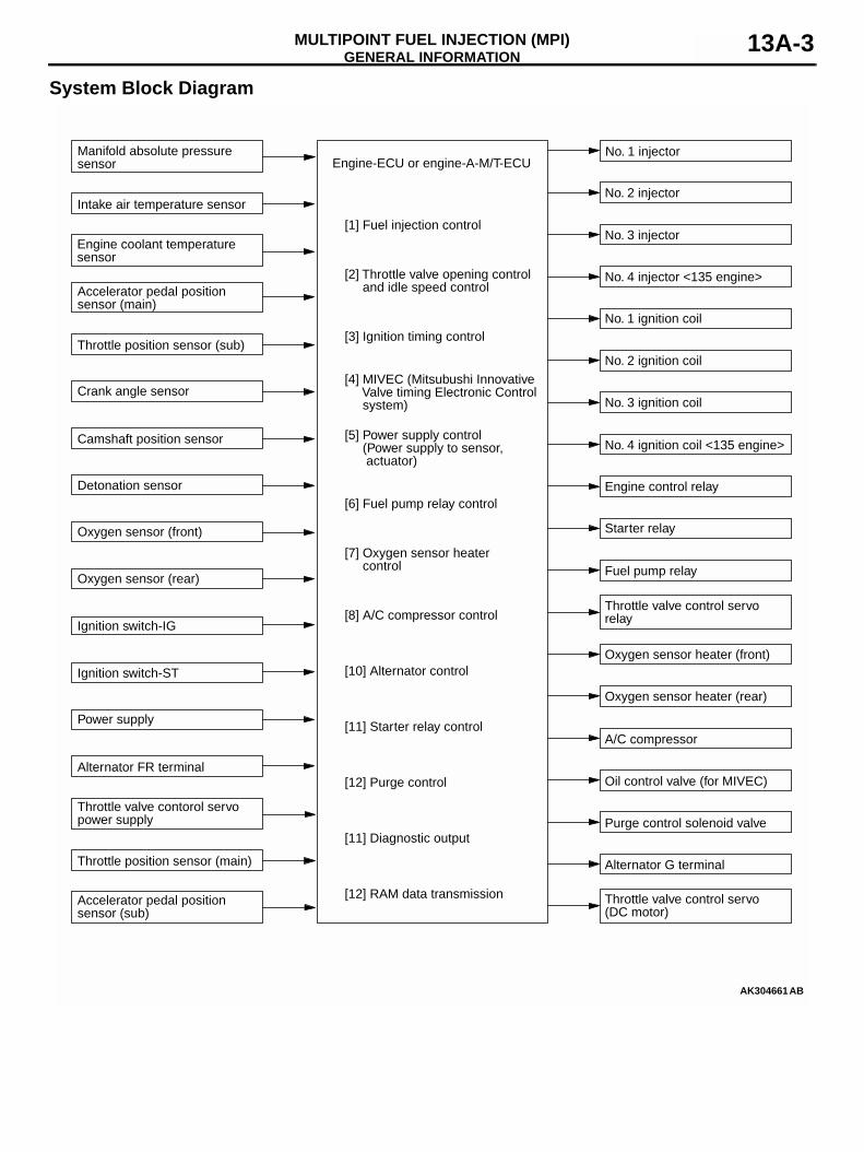
The engine control system consists of sensors that detect the conditions of the engine and the actuators that operate under the control of the engine-ECU or engine automated manual transmission electronic control unit (engine-A-M/T-ECU), which calculates and determines the engine control contents based on the signals provided by the sensors. The
engine-ECU or engine-A-M/T-ECU effects fuel injec-tion control, idle speed control, ignition timing control, and fuel pump control. In addition, the engine-ECU or engine-A-M/T-ECU contains a self-diagnosis sys-tem to facilitate the diagnosis of malfunctions in the major sensors and actuators.
GENERAL INFORMATIONMULTIPOINT FUEL INJECTION (MPI) 13A-3
System Block Diagram
AK304661
[1] Fuel injection control
[3] Ignition timing control
[5] Power supply control (Power supply to sensor, actuator)
[6] Fuel pump relay control
[7] Oxygen sensor heater control
[8] A/C compressor control
[12] Purge control
[4] MIVEC (Mitsubushi Innovative Valve timing Electronic Control system)
[10] Alternator control
[11] Diagnostic output
[12] RAM data transmission
[2] Throttle valve opening control and idle speed control
Manifold absolute pressuresensor
Engine coolant temperaturesensor
Accelerator pedal position sensor (main)
Throttle position sensor (sub)
Crank angle sensor
Detonation sensor
Camshaft position sensor
Oxygen sensor (front)
Oxygen sensor (rear)
Ignition switch-IG
Ignition switch-ST
Power supply
Alternator FR terminal
Intake air temperature sensor
Throttle valve control servo(DC motor)
Accelerator pedal position sensor (sub)
Throttle position sensor (main)
Throttle valve contorol servopower supply
No. 1 injector
No. 2 injector
No. 3 injector
No. 1 ignition coil
No. 2 ignition coil
No. 3 ignition coil
Engine control relay
Fuel pump relay
Oxygen sensor heater (front)
Purge control solenoid valve
Oil control valve (for MIVEC)
Oxygen sensor heater (rear)
Alternator G terminal
Throttle valve control servorelay
Engine-ECU or engine-A-M/T-ECU
Starter relay
A/C compressor
AB
[11] Starter relay control
No. 4 injector <135 engine>
No. 4 ignition coil <135 engine>
GENERAL INFORMATIONMULTIPOINT FUEL INJECTION (MPI)13A-4
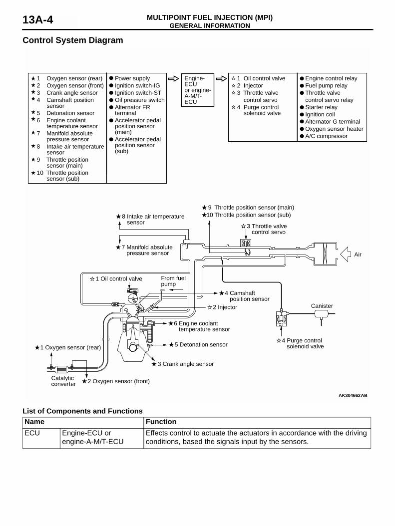
Control System Diagram
List of Components and Functions
AK304662
3 Throttle valve control servo
9 Throttle position sensor (main)
3 Crank angle sensor
2 Oxygen sensor (front)
4 Purge control solenoid valve
2 Injector Canister
1 Oxygen sensor (rear)
Air
5 Detonation sensor
Catalyticconverter
7 Manifold absolute pressure sensor
8 Intake air temperature sensor
4 Camshaft position sensor
10 Throttle position sensor (sub)
6 Engine coolant temperature sensor
1 Oil control valve
1 Oxygen sensor (rear)2 Oxygen sensor (front)3 Crank angle sensor4 Camshaft position
sensor5 Detonation sensor6 Engine coolant
temperature sensor7 Manifold absolute
pressure sensor8 Intake air temperature
sensor9 Throttle position
sensor (main)10 Throttle position
sensor (sub)
1 Oil control valve2 Injector3 Throttle valve control servo4 Purge control
solenoid valve
Power supplyIgnition switch-IGIgnition switch-STOil pressure switchAlternator FR terminalAccelerator pedal position sensor (main)Accelerator pedal position sensor (sub)
Engine control relayFuel pump relayThrottle valvecontrol servo relayStarter relayIgnition coilAlternator G terminalOxygen sensor heaterA/C compressor
From fuelpump
AB
Engine-ECU or engine-A-M/T-ECU
Name FunctionECU Engine-ECU or
engine-A-M/T-ECUEffects control to actuate the actuators in accordance with the driving conditions, based the signals input by the sensors.
GENERAL INFORMATIONMULTIPOINT FUEL INJECTION (MPI) 13A-5
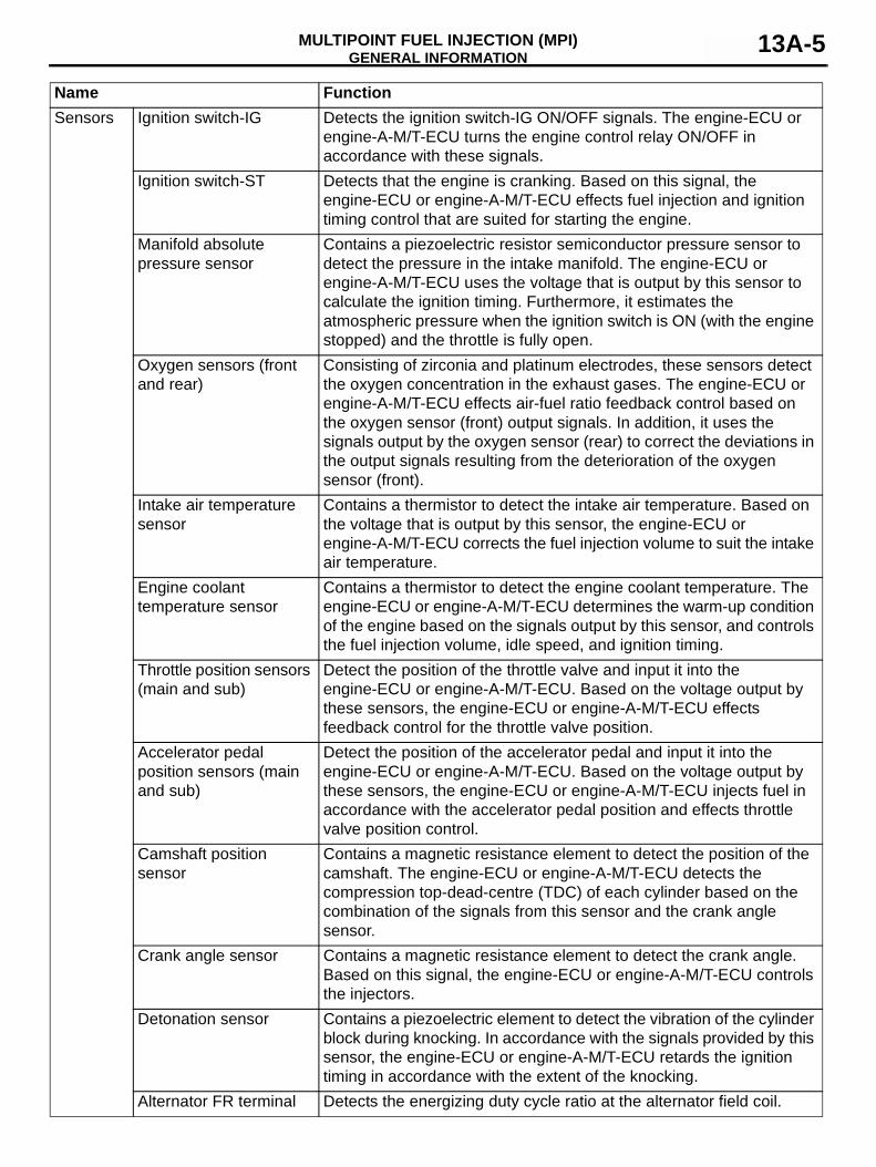
Sensors Ignition switch-IG Detects the ignition switch-IG ON/OFF signals. The engine-ECU or engine-A-M/T-ECU turns the engine control relay ON/OFF in accordance with these signals.
Ignition switch-ST Detects that the engine is cranking. Based on this signal, the engine-ECU or engine-A-M/T-ECU effects fuel injection and ignition timing control that are suited for starting the engine.
Manifold absolute pressure sensor
Contains a piezoelectric resistor semiconductor pressure sensor to detect the pressure in the intake manifold. The engine-ECU or engine-A-M/T-ECU uses the voltage that is output by this sensor to calculate the ignition timing. Furthermore, it estimates the atmospheric pressure when the ignition switch is ON (with the engine stopped) and the throttle is fully open.
Oxygen sensors (front and rear)
Consisting of zirconia and platinum electrodes, these sensors detect the oxygen concentration in the exhaust gases. The engine-ECU or engine-A-M/T-ECU effects air-fuel ratio feedback control based on the oxygen sensor (front) output signals. In addition, it uses the signals output by the oxygen sensor (rear) to correct the deviations in the output signals resulting from the deterioration of the oxygen sensor (front).
Intake air temperature sensor
Contains a thermistor to detect the intake air temperature. Based on the voltage that is output by this sensor, the engine-ECU or engine-A-M/T-ECU corrects the fuel injection volume to suit the intake air temperature.
Engine coolant temperature sensor
Contains a thermistor to detect the engine coolant temperature. The engine-ECU or engine-A-M/T-ECU determines the warm-up condition of the engine based on the signals output by this sensor, and controls the fuel injection volume, idle speed, and ignition timing.
Throttle position sensors (main and sub)
Detect the position of the throttle valve and input it into the engine-ECU or engine-A-M/T-ECU. Based on the voltage output by these sensors, the engine-ECU or engine-A-M/T-ECU effects feedback control for the throttle valve position.
Accelerator pedal position sensors (main and sub)
Detect the position of the accelerator pedal and input it into the engine-ECU or engine-A-M/T-ECU. Based on the voltage output by these sensors, the engine-ECU or engine-A-M/T-ECU injects fuel in accordance with the accelerator pedal position and effects throttle valve position control.
Camshaft position sensor
Contains a magnetic resistance element to detect the position of the camshaft. The engine-ECU or engine-A-M/T-ECU detects the compression top-dead-centre (TDC) of each cylinder based on the combination of the signals from this sensor and the crank angle sensor.
Crank angle sensor Contains a magnetic resistance element to detect the crank angle. Based on this signal, the engine-ECU or engine-A-M/T-ECU controls the injectors.
Detonation sensor Contains a piezoelectric element to detect the vibration of the cylinder block during knocking. In accordance with the signals provided by this sensor, the engine-ECU or engine-A-M/T-ECU retards the ignition timing in accordance with the extent of the knocking.
Alternator FR terminal Detects the energizing duty cycle ratio at the alternator field coil.
Name Function
GENERAL INFORMATIONMULTIPOINT FUEL INJECTION (MPI)13A-6
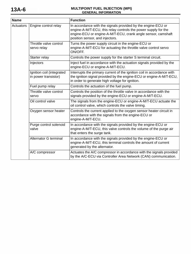
Actuators Engine control relay In accordance with the signals provided by the engine-ECU or engine-A-M/T-ECU, this relay controls the power supply for the engine-ECU or engine-A-M/T-ECU, crank angle sensor, camshaft position sensor, and injectors.
Throttle valve control servo relay
Turns the power supply circuit in the engine-ECU or engine-A-M/T-ECU for actuating the throttle valve control servo ON/OFF.
Starter relay Controls the power supply for the starter S terminal circuit.Injectors Inject fuel in accordance with the actuation signals provided by the
engine-ECU or engine-A-M/T-ECU.Ignition coil (integrated in power transistor)
Interrupts the primary current of the ignition coil in accordance with the ignition signal provided by the engine-ECU or engine-A-M/T-ECU, in order to generate high voltage for ignition.
Fuel pump relay Controls the actuation of the fuel pump.Throttle valve control servo
Controls the position of the throttle valve in accordance with the signals provided by the engine-ECU or engine-A-M/T-ECU.
Oil control valve The signals from the engine-ECU or engine-A-M/T-ECU actuate the oil control valve, which controls the valve timing.
Oxygen sensor heater Controls the current applied to the oxygen sensor heater circuit in accordance with the signals from the engine-ECU or engine-A-M/T-ECU.
Purge control solenoid valve
In accordance with the signals provided by the engine-ECU or engine-A-M/T-ECU, this valve controls the volume of the purge air that enters the surge tank.
Alternator G terminal In accordance with the signals provided by the engine-ECU or engine-A-M/T-ECU, this terminal controls the amount of current generated by the alternator.
A/C compressor Actuates the A/C compressor in accordance with the signals provided by the A/C-ECU via Controller Area Network (CAN) communication.
Name Function
CONTROL SYSTEMMULTIPOINT FUEL INJECTION (MPI) 13A-7
CONTROL SYSTEMM2132000500028
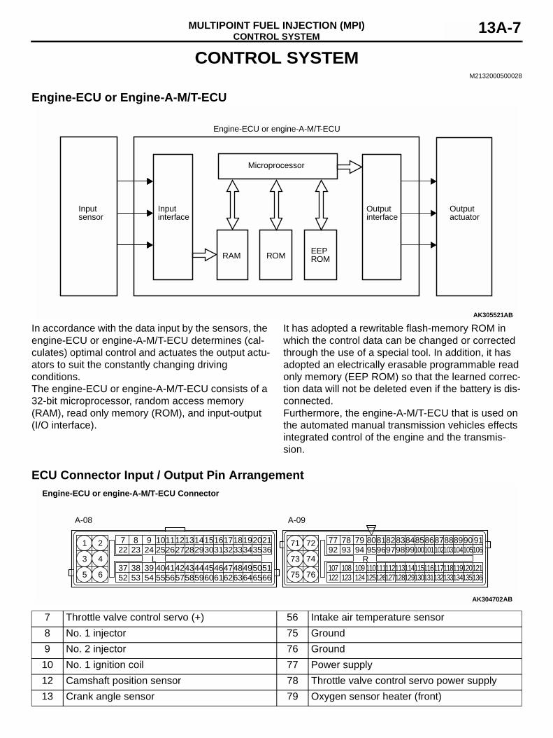
Engine-ECU or Engine-A-M/T-ECU
In accordance with the data input by the sensors, the engine-ECU or engine-A-M/T-ECU determines (cal-culates) optimal control and actuates the output actu-ators to suit the constantly changing driving conditions. The engine-ECU or engine-A-M/T-ECU consists of a 32-bit microprocessor, random access memory (RAM), read only memory (ROM), and input-output (I/O interface).
It has adopted a rewritable flash-memory ROM in which the control data can be changed or corrected through the use of a special tool. In addition, it has adopted an electrically erasable programmable read only memory (EEP ROM) so that the learned correc-tion data will not be deleted even if the battery is dis-connected.Furthermore, the engine-A-M/T-ECU that is used on the automated manual transmission vehicles effects integrated control of the engine and the transmis-sion.
ECU Connector Input / Output Pin Arrangement
AK305521
Engine-ECU or engine-A-M/T-ECU
Microprocessor
RAM
Input interface
Input sensor
Output interface
Output actuator
AB
ROMEEPROM
AK304702
6146
31
6449
1934
50516665
3621
3520
47486362
3318
3217
5843
28
44456059
301615
2914
41425756
271213
2611
5338
238
39 4054 55
249
L2510
3752
227
5
3
1
6
4
293
71 72
75
73
76
749277
9883
9594R
96978078 79 8182
99868485
107122
108123
109124
110125
111126
112127
113128
114129
115130
116131
117132
118133
119134
120135
121136
101100 1021031041051068788 919089
Engine-ECU or engine-A-M/T-ECU Connector
A-08 A-09
AB
7 Throttle valve control servo (+) 56 Intake air temperature sensor8 No. 1 injector 75 Ground9 No. 2 injector 76 Ground10 No. 1 ignition coil 77 Power supply12 Camshaft position sensor 78 Throttle valve control servo power supply13 Crank angle sensor 79 Oxygen sensor heater (front)
SENSORMULTIPOINT FUEL INJECTION (MPI)13A-8
SENSORM2132001000219
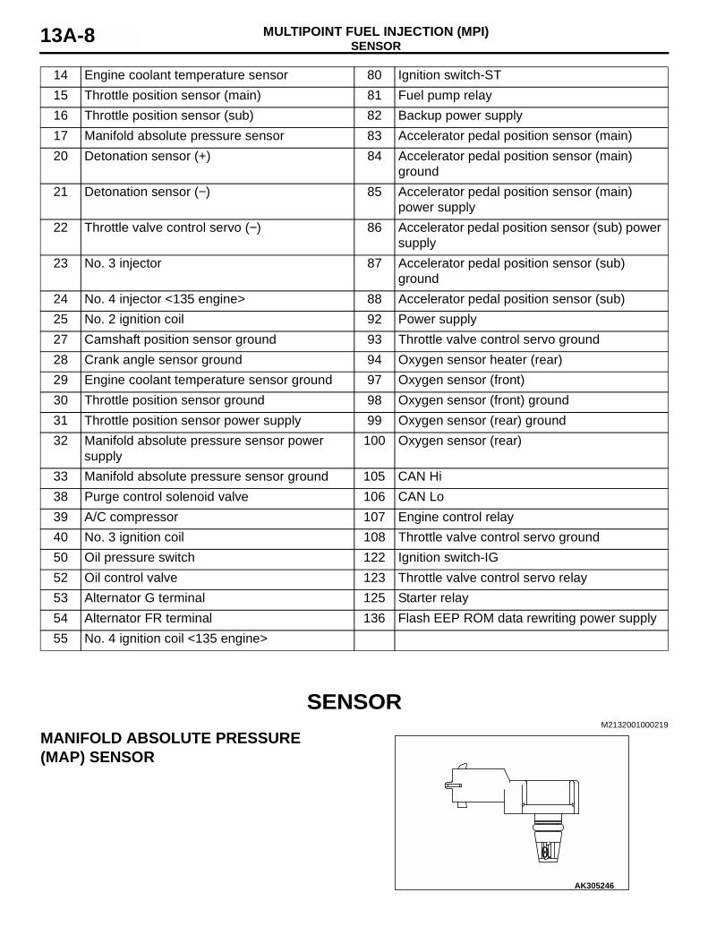
MANIFOLD ABSOLUTE PRESSURE (MAP) SENSOR
14 Engine coolant temperature sensor 80 Ignition switch-ST15 Throttle position sensor (main) 81 Fuel pump relay16 Throttle position sensor (sub) 82 Backup power supply17 Manifold absolute pressure sensor 83 Accelerator pedal position sensor (main)20 Detonation sensor (+) 84 Accelerator pedal position sensor (main)
ground21 Detonation sensor (−) 85 Accelerator pedal position sensor (main)
power supply22 Throttle valve control servo (−) 86 Accelerator pedal position sensor (sub) power
supply23 No. 3 injector 87 Accelerator pedal position sensor (sub)
ground24 No. 4 injector <135 engine> 88 Accelerator pedal position sensor (sub)25 No. 2 ignition coil 92 Power supply27 Camshaft position sensor ground 93 Throttle valve control servo ground28 Crank angle sensor ground 94 Oxygen sensor heater (rear)29 Engine coolant temperature sensor ground 97 Oxygen sensor (front)30 Throttle position sensor ground 98 Oxygen sensor (front) ground31 Throttle position sensor power supply 99 Oxygen sensor (rear) ground32 Manifold absolute pressure sensor power
supply100 Oxygen sensor (rear)
33 Manifold absolute pressure sensor ground 105 CAN Hi38 Purge control solenoid valve 106 CAN Lo39 A/C compressor 107 Engine control relay40 No. 3 ignition coil 108 Throttle valve control servo ground50 Oil pressure switch 122 Ignition switch-IG52 Oil control valve 123 Throttle valve control servo relay53 Alternator G terminal 125 Starter relay54 Alternator FR terminal 136 Flash EEP ROM data rewriting power supply55 No. 4 ignition coil <135 engine>
AK305246
SENSORMULTIPOINT FUEL INJECTION (MPI) 13A-9
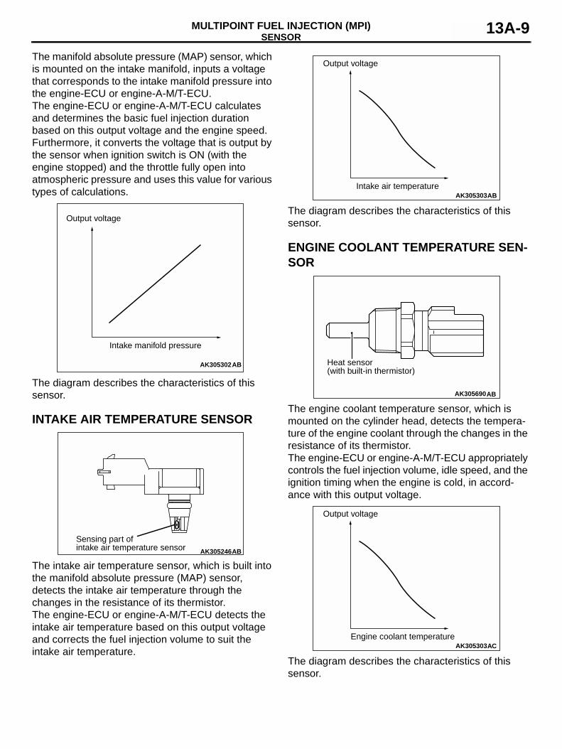
The manifold absolute pressure (MAP) sensor, which is mounted on the intake manifold, inputs a voltage that corresponds to the intake manifold pressure into the engine-ECU or engine-A-M/T-ECU.The engine-ECU or engine-A-M/T-ECU calculates and determines the basic fuel injection duration based on this output voltage and the engine speed.Furthermore, it converts the voltage that is output by the sensor when ignition switch is ON (with the engine stopped) and the throttle fully open into atmospheric pressure and uses this value for various types of calculations.
The diagram describes the characteristics of this sensor.
INTAKE AIR TEMPERATURE SENSOR
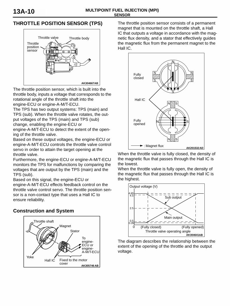
The intake air temperature sensor, which is built into the manifold absolute pressure (MAP) sensor, detects the intake air temperature through the changes in the resistance of its thermistor.The engine-ECU or engine-A-M/T-ECU detects the intake air temperature based on this output voltage and corrects the fuel injection volume to suit the intake air temperature.
The diagram describes the characteristics of this sensor.
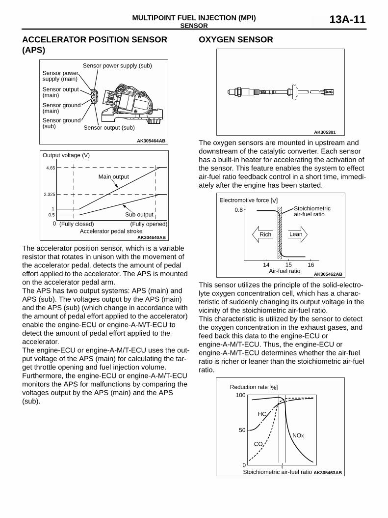
ENGINE COOLANT TEMPERATURE SEN-SOR
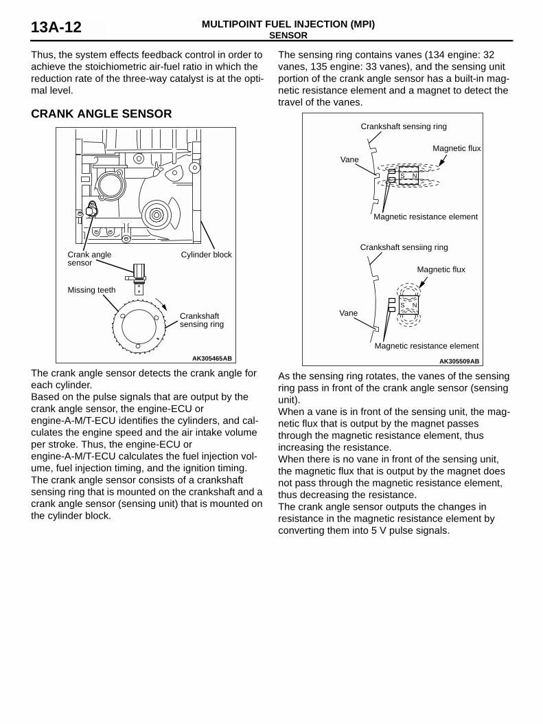
The engine coolant temperature sensor, which is mounted on the cylinder head, detects the tempera-ture of the engine coolant through the changes in the resistance of its thermistor.The engine-ECU or engine-A-M/T-ECU appropriately controls the fuel injection volume, idle speed, and the ignition timing when the engine is cold, in accord-ance with this output voltage.
The diagram describes the characteristics of this sensor.
AK305302AB
Intake manifold pressure
Output voltage
AK305246
Sensing part ofintake air temperature sensor AB
AK305303AB
Output voltage
Intake air temperature
AK305690AB
Heat sensor (with built-in thermistor)
AK305303AC
Output voltage
Engine coolant temperature
SENSORMULTIPOINT FUEL INJECTION (MPI)13A-10
THROTTLE POSITION SENSOR (TPS)
The throttle position sensor, which is built into the throttle body, inputs a voltage that corresponds to the rotational angle of the throttle shaft into the engine-ECU or engine-A-M/T-ECU.The TPS has two output systems: TPS (main) and TPS (sub). When the throttle valve rotates, the out-put voltages of the TPS (main) and TPS (sub) change, enabling the engine-ECU or engine-A-M/T-ECU to detect the extent of the open-ing of the throttle valve.Based on these output voltages, the engine-ECU or engine-A-M/T-ECU controls the throttle valve control servo in order to attain the target opening at the throttle valve.Furthermore, the engine-ECU or engine-A-M/T-ECU monitors the TPS for malfunctions by comparing the voltages that are output by the TPS (main) and the TPS (sub).Based on this signal, the engine-ECU or engine-A-M/T-ECU effects feedback control on the throttle valve control servo. The throttle position sen-sor is a non-contact type that uses a Hall IC to ensure reliability.
Construction and System
The throttle position sensor consists of a permanent magnet that is mounted on the throttle shaft, a Hall IC that outputs a voltage in accordance with the mag-netic flux density, and a stator that effectively guides the magnetic flux from the permanent magnet to the Hall IC.
When the throttle valve is fully closed, the density of the magnetic flux that passes through the Hall IC is the lowest.When the throttle valve is fully open, the density of the magnetic flux that passes through the Hall IC is the highest.
The diagram describes the relationship between the extent of the opening of the throttle and the output voltage.
AK304667AB
Throttle valve
Throttlepositionsensor
Throttle body
AK305746
Throttle shaftMagnet
Stator
Toengine-ECU orengine-A-M/T-ECU
YokeHall IC Fixed to the motor
coverAB
AK201532AD
Hall IC
Fullyclosed
N
N SFullyopened
: Magnet flux
N
S
N S
N S
N
S
S
AK304641
Output voltage (V)
Sub output
Main output0.5
2.5
4.54.65
0Throttle valve operating angle
AB
(Fully opened)(Fully closed)0.35
SENSORMULTIPOINT FUEL INJECTION (MPI) 13A-11
ACCELERATOR POSITION SENSOR (APS)
The accelerator position sensor, which is a variable resistor that rotates in unison with the movement of the accelerator pedal, detects the amount of pedal effort applied to the accelerator. The APS is mounted on the accelerator pedal arm.The APS has two output systems: APS (main) and APS (sub). The voltages output by the APS (main) and the APS (sub) (which change in accordance with the amount of pedal effort applied to the accelerator) enable the engine-ECU or engine-A-M/T-ECU to detect the amount of pedal effort applied to the accelerator.The engine-ECU or engine-A-M/T-ECU uses the out-put voltage of the APS (main) for calculating the tar-get throttle opening and fuel injection volume.Furthermore, the engine-ECU or engine-A-M/T-ECU monitors the APS for malfunctions by comparing the voltages output by the APS (main) and the APS (sub).
OXYGEN SENSOR
The oxygen sensors are mounted in upstream and downstream of the catalytic converter. Each sensor has a built-in heater for accelerating the activation of the sensor. This feature enables the system to effect air-fuel ratio feedback control in a short time, immedi-ately after the engine has been started.
This sensor utilizes the principle of the solid-electro-lyte oxygen concentration cell, which has a charac-teristic of suddenly changing its output voltage in the vicinity of the stoichiometric air-fuel ratio.This characteristic is utilized by the sensor to detect the oxygen concentration in the exhaust gases, and feed back this data to the engine-ECU or engine-A-M/T-ECU. Thus, the engine-ECU or engine-A-M/T-ECU determines whether the air-fuel ratio is richer or leaner than the stoichiometric air-fuel ratio.
AK305464AB
Sensor powersupply (main)
Sensor output(main)
Sensor ground(main)
Sensor ground(sub)
Sensor power supply (sub)
Sensor output (sub)
AK304640
Output voltage (V)
Sub output
Main output
0.5
2.325
1
4.65
0Accelerator pedal stroke
AB
(Fully opened)(Fully closed)
AK305301
AK305462
0.8
14 15 16Air-fuel ratio
Stoichiometric air-fuel ratio
Rich
Electromotive force [V]
Lean
AB
AK305463
0ABStoichiometric air-fuel ratio
100
50
HC
CO
NOx
Reduction rate [%]
SENSORMULTIPOINT FUEL INJECTION (MPI)13A-12
Thus, the system effects feedback control in order to achieve the stoichiometric air-fuel ratio in which the reduction rate of the three-way catalyst is at the opti-mal level.
CRANK ANGLE SENSOR
The crank angle sensor detects the crank angle for each cylinder.Based on the pulse signals that are output by the crank angle sensor, the engine-ECU or engine-A-M/T-ECU identifies the cylinders, and cal-culates the engine speed and the air intake volume per stroke. Thus, the engine-ECU or engine-A-M/T-ECU calculates the fuel injection vol-ume, fuel injection timing, and the ignition timing.The crank angle sensor consists of a crankshaft sensing ring that is mounted on the crankshaft and a crank angle sensor (sensing unit) that is mounted on the cylinder block.
The sensing ring contains vanes (134 engine: 32 vanes, 135 engine: 33 vanes), and the sensing unit portion of the crank angle sensor has a built-in mag-netic resistance element and a magnet to detect the travel of the vanes.
As the sensing ring rotates, the vanes of the sensing ring pass in front of the crank angle sensor (sensing unit).When a vane is in front of the sensing unit, the mag-netic flux that is output by the magnet passes through the magnetic resistance element, thus increasing the resistance.When there is no vane in front of the sensing unit, the magnetic flux that is output by the magnet does not pass through the magnetic resistance element, thus decreasing the resistance.The crank angle sensor outputs the changes in resistance in the magnetic resistance element by converting them into 5 V pulse signals.
AK305465AB
Crankshaft sensing ring
Missing teeth
Crank angle sensor
Cylinder block
AK305509
Crankshaft sensing ring
Vane
Magnetic resistance element
Crankshaft sensiing ring
Vane
Magnetic resistance element
Magnetic flux
S N
S N
Magnetic flux
AB
SENSORMULTIPOINT FUEL INJECTION (MPI) 13A-13
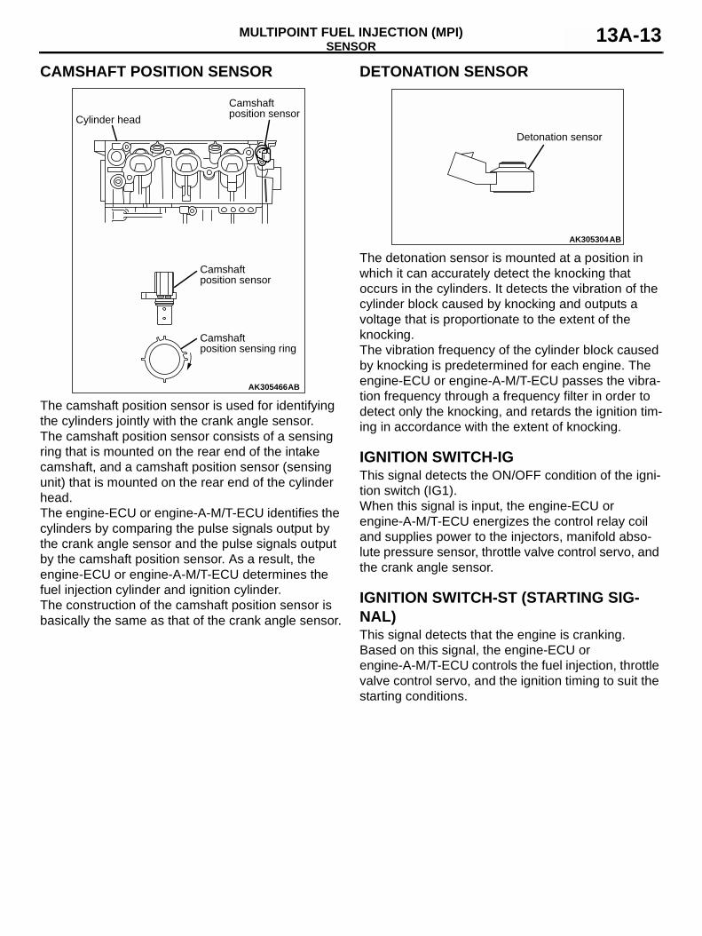
CAMSHAFT POSITION SENSOR
The camshaft position sensor is used for identifying the cylinders jointly with the crank angle sensor.The camshaft position sensor consists of a sensing ring that is mounted on the rear end of the intake camshaft, and a camshaft position sensor (sensing unit) that is mounted on the rear end of the cylinder head.The engine-ECU or engine-A-M/T-ECU identifies the cylinders by comparing the pulse signals output by the crank angle sensor and the pulse signals output by the camshaft position sensor. As a result, the engine-ECU or engine-A-M/T-ECU determines the fuel injection cylinder and ignition cylinder.The construction of the camshaft position sensor is basically the same as that of the crank angle sensor.
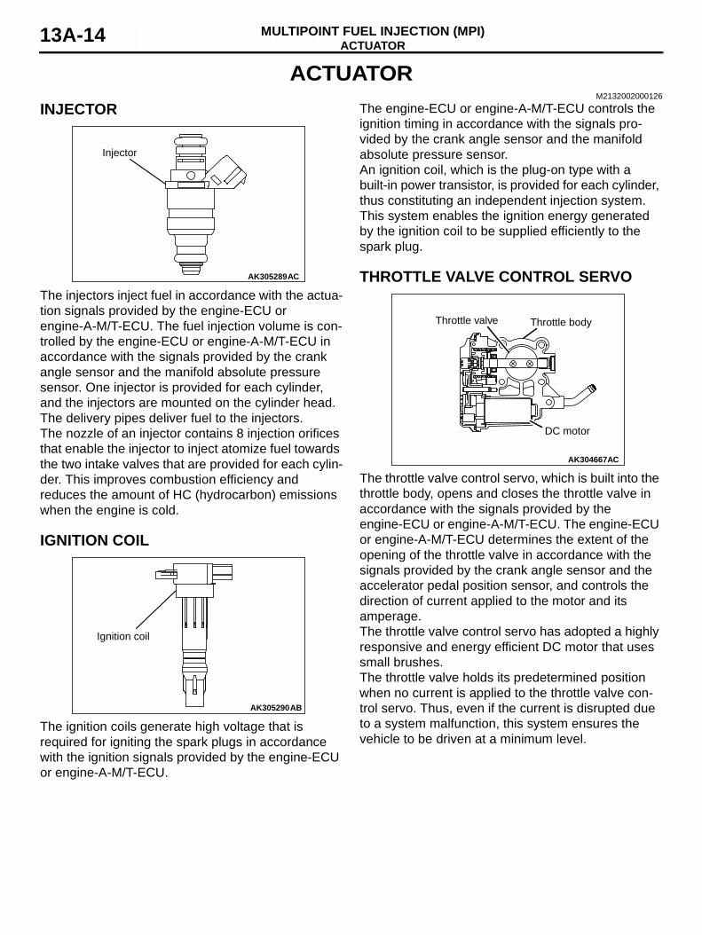
DETONATION SENSOR
The detonation sensor is mounted at a position in which it can accurately detect the knocking that occurs in the cylinders. It detects the vibration of the cylinder block caused by knocking and outputs a voltage that is proportionate to the extent of the knocking.The vibration frequency of the cylinder block caused by knocking is predetermined for each engine. The engine-ECU or engine-A-M/T-ECU passes the vibra-tion frequency through a frequency filter in order to detect only the knocking, and retards the ignition tim-ing in accordance with the extent of knocking.
IGNITION SWITCH-IGThis signal detects the ON/OFF condition of the igni-tion switch (IG1).When this signal is input, the engine-ECU or engine-A-M/T-ECU energizes the control relay coil and supplies power to the injectors, manifold abso-lute pressure sensor, throttle valve control servo, and the crank angle sensor.
IGNITION SWITCH-ST (STARTING SIG-NAL)This signal detects that the engine is cranking.Based on this signal, the engine-ECU or engine-A-M/T-ECU controls the fuel injection, throttle valve control servo, and the ignition timing to suit the starting conditions.
AK305466
Camshaft position sensor
Camshaft position sensor
Camshaft position sensing ring
Cylinder head
AB
AK305304
Detonation sensor
AB
ACTUATORMULTIPOINT FUEL INJECTION (MPI)13A-14
ACTUATORM2132002000126
INJECTOR
The injectors inject fuel in accordance with the actua-tion signals provided by the engine-ECU or engine-A-M/T-ECU. The fuel injection volume is con-trolled by the engine-ECU or engine-A-M/T-ECU in accordance with the signals provided by the crank angle sensor and the manifold absolute pressure sensor. One injector is provided for each cylinder, and the injectors are mounted on the cylinder head.The delivery pipes deliver fuel to the injectors.The nozzle of an injector contains 8 injection orifices that enable the injector to inject atomize fuel towards the two intake valves that are provided for each cylin-der. This improves combustion efficiency and reduces the amount of HC (hydrocarbon) emissions when the engine is cold.
IGNITION COIL
The ignition coils generate high voltage that is required for igniting the spark plugs in accordance with the ignition signals provided by the engine-ECU or engine-A-M/T-ECU.
The engine-ECU or engine-A-M/T-ECU controls the ignition timing in accordance with the signals pro-vided by the crank angle sensor and the manifold absolute pressure sensor.An ignition coil, which is the plug-on type with a built-in power transistor, is provided for each cylinder, thus constituting an independent injection system. This system enables the ignition energy generated by the ignition coil to be supplied efficiently to the spark plug.
THROTTLE VALVE CONTROL SERVO
The throttle valve control servo, which is built into the throttle body, opens and closes the throttle valve in accordance with the signals provided by the engine-ECU or engine-A-M/T-ECU. The engine-ECU or engine-A-M/T-ECU determines the extent of the opening of the throttle valve in accordance with the signals provided by the crank angle sensor and the accelerator pedal position sensor, and controls the direction of current applied to the motor and its amperage.The throttle valve control servo has adopted a highly responsive and energy efficient DC motor that uses small brushes.The throttle valve holds its predetermined position when no current is applied to the throttle valve con-trol servo. Thus, even if the current is disrupted due to a system malfunction, this system ensures the vehicle to be driven at a minimum level.
AK305289
Injector
AC
AK305290
Ignition coil
AB
AK304667AC
Throttle valve
DC motor
Throttle body
FUEL INJECTION CONTROLMULTIPOINT FUEL INJECTION (MPI) 13A-15
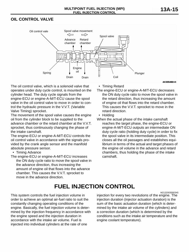
OIL CONTROL VALVE
The oil control valve, which is a solenoid valve that operates under duty cycle control, is mounted on the cylinder head. The duty cycle signals from the engine-ECU or engine-A-M/T-ECU cause the spool valve in the oil control valve to move in order to con-trol the hydraulic pressure in the V.V.T. (Variable Valve Timing) sprocket.The movement of the spool valve causes the engine oil from the cylinder block to be supplied to the advance chamber or the retard chamber at the V.V.T. sprocket, thus continuously changing the phase of the intake camshaft.The engine-ECU or engine-A-M/T-ECU controls the oil control valve in accordance with the signals pro-vided by the crank angle sensor and the manifold absolute pressure sensor.• Timing Advance
The engine-ECU or engine-A-M/T-ECU increases the ON duty cycle ratio to move the spool valve in the advance direction, thus increasing the amount of engine oil that flows into the advance chamber. This causes the V.V.T. sprocket to move in the advance direction.
• Timing RetardThe engine-ECU or engine-A-M/T-ECU decreases
the ON duty cycle ratio to move the spool valve in the retard direction, thus increasing the amount of engine oil that flows into the retard chamber. This causes the V.V.T. sprocket to move in the retard direction.
• HoldingWhen the actual phase of the intake camshaft
reaches the target phase, the engine-ECU or engine-A-M/T-ECU outputs an intermediate ON duty cycle ratio (holding duty cycle) in order to fix the spool valve in its intermediate position. This closes all the oil passages and establishes equi-librium in terms of the actual and target phases of the engine oil volume in the advance and retard chambers, thus holding the phase of the intake camshaft.
FUEL INJECTION CONTROLM2132003000345
This system controls the fuel injection volume in order to achieve an optimal air-fuel ratio to suit the constantly changing operating conditions of the engine. Basically, the fuel injection volume is deter-mined by the injection frequency in accordance with the engine speed and the injection duration in accordance with the intake air volume. Fuel is injected into individual cylinders at the rate of one
injection for every two revolutions of the engine. The injection duration (injector actuation duration) is the sum of the basic actuation duration (which is deter-mined by the intake air volume of the cylinders) and a correction duration (which is determined by the conditions such as the intake air temperature and the engine coolant temperature).
AK305488
Engineoil
DrainDrain
Retardchamber
Advancechamber
Spring
CoilPlunger
Spool valve movementOil control vale
Spool valve
AK305488AB
FUEL INJECTION CONTROLMULTIPOINT FUEL INJECTION (MPI)13A-16
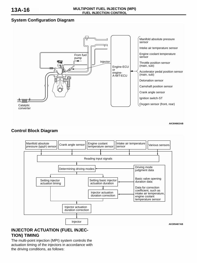
System Configuration Diagram
Control Block Diagram
INJECTOR ACTUATION (FUEL INJEC-TION) TIMINGThe multi-point injection (MPI) system controls the actuation timing of the injectors in accordance with the driving conditions, as follows:
AK304663AB
Catalyticconverter
Injector
Manifold absolute pressuresensor
Inteke air temperature sensor
Engine coolant temperaturesensor
Throttle position sensor(main, sub)
Accelerator pedal position sensor(main, sub)
Detonation sensor
Camshaft position sensor
Crank angle sensor
Ignition switch-ST
Oxygen sensor (front, rear)
From fuelpump
Engine-ECUorengine-A-M/T-ECU
AK305467
Manifold absolute pressure (MAP) sensor
Driving mode judgment data
Crank angle sensor Engine coolant temperature sensor
Intake air temperaturesensor
Injector actuation duration correction
Setting basic injector actuation duration
Injector actuation duration correction
Various sensors
Determining driving modes
Setting injector actuation timing
Basic valve opening duration data
Data for correctioncoefficient, such as intake air temperature, engine coolant temperature sensor
Reading input signals
InjectorAB
FUEL INJECTION CONTROLMULTIPOINT FUEL INJECTION (MPI) 13A-17
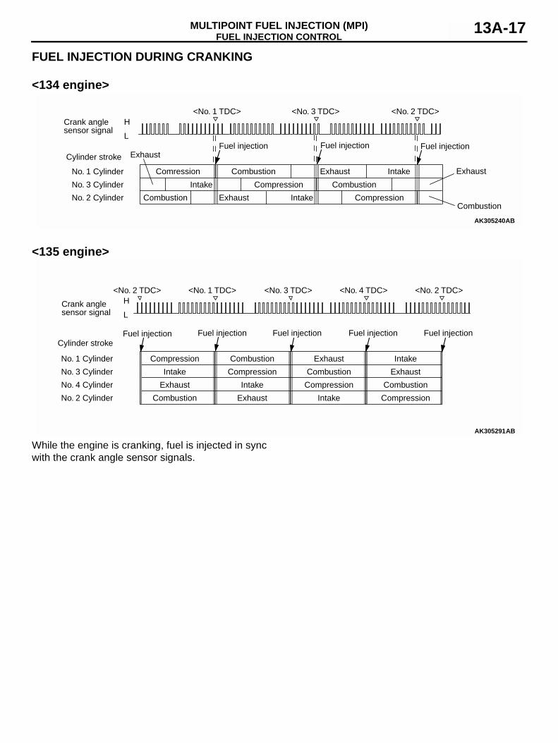
FUEL INJECTION DURING CRANKING
<134 engine>
<135 engine>
While the engine is cranking, fuel is injected in sync with the crank angle sensor signals.
AK305240AB
<No. 1 TDC>H
L
<No. 3 TDC> <No. 2 TDC>Crank anglesensor signal
Cylinder stroke
No. 1 Cylinder
No. 3 Cylinder
No. 2 Cylinder
Fuel injection
Intake
Intake
Comression
Compression
Compression
Combustion
Combustion
Combustion
ExhaustExhaust
Exhaust
Intake
Combustion
ExhaustFuel injection Fuel injection
AK305291AB
<No. 2 TDC>H
L
<No. 1 TDC> <No. 3 TDC> <No. 4 TDC> <No. 2 TDC>
Crank anglesensor signal
Cylinder stroke
No. 1 Cylinder
No. 3 Cylinder
No. 4 Cylinder
No. 2 Cylinder
Intake
Intake
Intake
Fuel injection
Compression
Compression
Compression
Compression
Combustion
Combustion
Combustion
Combustion
Exhaust
Exhaust
Exhaust
Exhaust
Intake
Fuel injectionFuel injectionFuel injectionFuel injection
FUEL INJECTION CONTROLMULTIPOINT FUEL INJECTION (MPI)13A-18
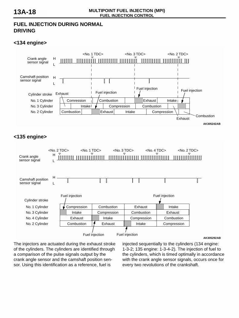
FUEL INJECTION DURING NORMAL DRIVING
<134 engine>
<135 engine>
The injectors are actuated during the exhaust stroke of the cylinders. The cylinders are identified through a comparison of the pulse signals output by the crank angle sensor and the camshaft position sen-sor. Using this identification as a reference, fuel is
injected sequentially to the cylinders (134 engine: 1-3-2; 135 engine: 1-3-4-2). The injection of fuel to the cylinders, which is timed optimally in accordance with the crank angle sensor signals, occurs once for every two revolutions of the crankshaft.
AK305242AB
<No. 1 TDC>
H
L
H
L
<No. 3 TDC> <No. 2 TDC>Crank anglesensor signal
Camshaft position sensor signal
Cylinder stroke
No. 1 Cylinder
No. 3 Cylinder
No. 2 Cylinder
Intake
Intake
Fuel injection
Comression
Compression
Compression
Combustion
Combustion
Combustion
Exhaust
Exhaust
Exhaust
Intake
Fuel injection Fuel injectionExhaust
Combustion
AK305292AB
<No. 2 TDC>
H
L
H
L
<No. 1 TDC> <No. 3 TDC> <No. 4 TDC> <No. 2 TDC>
Crank anglesensor signal
Camshaft positionsensor signal
Cylinder stroke
No. 1 Cylinder
No. 3 Cylinder
No. 4 Cylinder
No. 2 Cylinder
Intake
Intake
Intake
Fuel injection
Compression
Compression
Compression
Compression
Combustion
Combustion
Combustion
Combustion
Exhaust
Exhaust
Exhaust
Exhaust
Intake
Fuel injectionFuel injection
Fuel injection
FUEL INJECTION CONTROLMULTIPOINT FUEL INJECTION (MPI) 13A-19
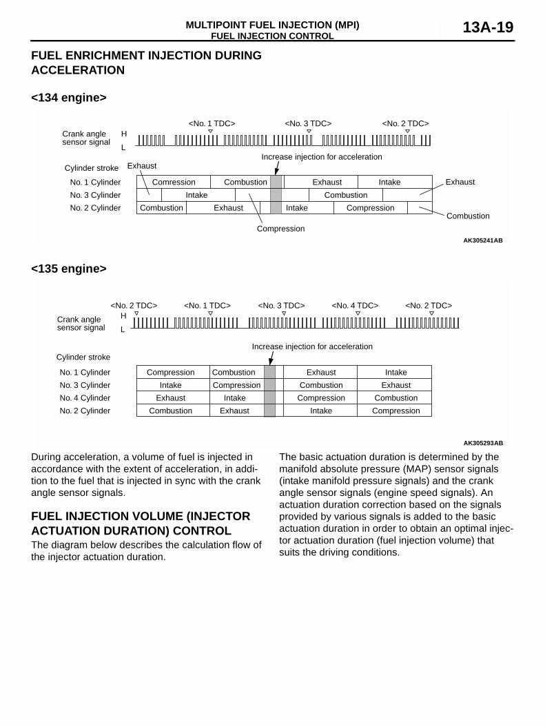
FUEL ENRICHMENT INJECTION DURING ACCELERATION
<134 engine>
<135 engine>
During acceleration, a volume of fuel is injected in accordance with the extent of acceleration, in addi-tion to the fuel that is injected in sync with the crank angle sensor signals.
FUEL INJECTION VOLUME (INJECTOR ACTUATION DURATION) CONTROLThe diagram below describes the calculation flow of the injector actuation duration.
The basic actuation duration is determined by the manifold absolute pressure (MAP) sensor signals (intake manifold pressure signals) and the crank angle sensor signals (engine speed signals). An actuation duration correction based on the signals provided by various signals is added to the basic actuation duration in order to obtain an optimal injec-tor actuation duration (fuel injection volume) that suits the driving conditions.
AK305241AB
<No. 1 TDC>H
L
<No. 3 TDC> <No. 2 TDC>Crank anglesensor signal
Cylinder stroke
No. 1 Cylinder
No. 3 Cylinder
No. 2 Cylinder
Increase injection for acceleration
Intake
Intake
Comression
Compression
Combustion
Combustion
Combustion
ExhaustExhaust
Exhaust
Intake
Combustion
Exhaust
Compression
AK305293AB
<No. 2 TDC>H
L
<No. 1 TDC> <No. 3 TDC> <No. 4 TDC> <No. 2 TDC>
Crank anglesensor signal
Cylinder stroke
No. 1 Cylinder
No. 3 Cylinder
No. 4 Cylinder
No. 2 Cylinder
Intake
Intake
Intake
Compression
Compression
Compression
Compression
Combustion
Combustion
Combustion
Combustion
Exhaust
Exhaust
Exhaust
Exhaust
Intake
Increase injection for acceleration
FUEL INJECTION CONTROLMULTIPOINT FUEL INJECTION (MPI)13A-20
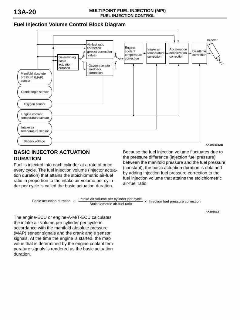
Fuel Injection Volume Control Block Diagram
BASIC INJECTOR ACTUATION DURATIONFuel is injected into each cylinder at a rate of once every cycle. The fuel injection volume (injector actua-tion duration) that attains the stoichiometric air-fuel ratio in proportion to the intake air volume per cylin-der per cycle is called the basic actuation duration.
Because the fuel injection volume fluctuates due to the pressure difference (injection fuel pressure) between the manifold pressure and the fuel pressure (constant), the basic actuation duration is obtained by adding injection fuel pressure correction to the fuel injection volume that attains the stoichiometric air-fuel ratio.
The engine-ECU or engine-A-M/T-ECU calculates the intake air volume per cylinder per cycle in accordance with the manifold absolute pressure (MAP) sensor signals and the crank angle sensor signals. At the time the engine is started, the map value that is determined by the engine coolant tem-perature signals is rendered as the basic actuation duration.
AK305468AB
Deadtime correction
Injector
Acceleration deceleration correction
Intake air temperature correction
Engine coolant temperature correction
Air-fuel ratio correction (preset correction value)
Determining basic actuationduration
Oxygen sensor feedback correctionManifold absolute
pressure (MAP) sensor
Battery voltage
Oxygen sensor
Crank angle sensor
Engine coolant temperature sensor
Intake air temperature sensor
AK305532
Basic actuation duration Intake air volume per cylinder per cycleStoichiometric air-fuel ratio
Injection fuel pressure correction
FUEL INJECTION CONTROLMULTIPOINT FUEL INJECTION (MPI) 13A-21
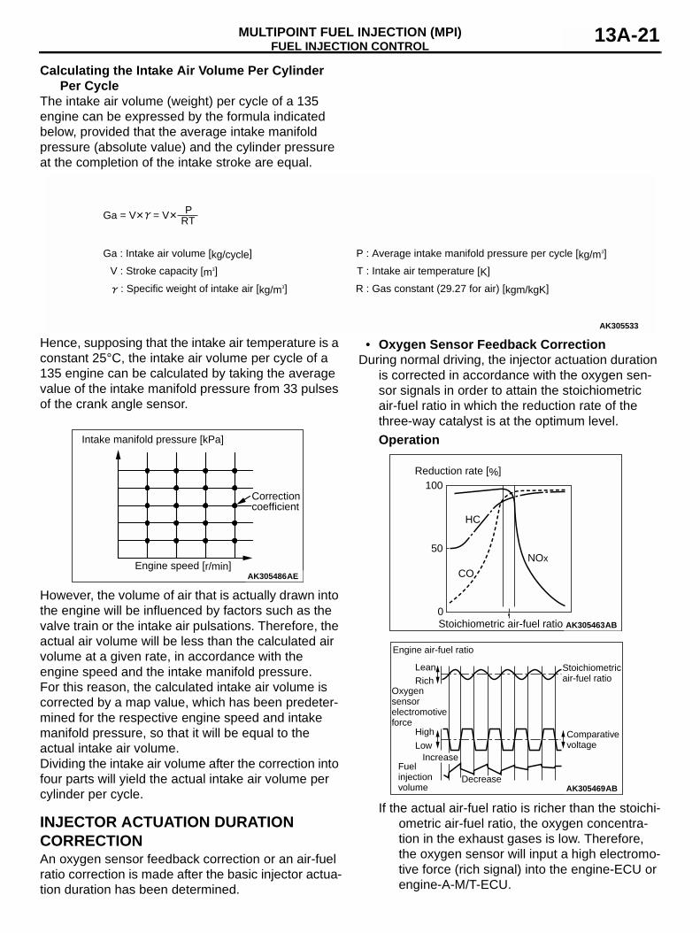
Calculating the Intake Air Volume Per Cylinder Per Cycle
The intake air volume (weight) per cycle of a 135 engine can be expressed by the formula indicated below, provided that the average intake manifold pressure (absolute value) and the cylinder pressure at the completion of the intake stroke are equal.
Hence, supposing that the intake air temperature is a constant 25°C, the intake air volume per cycle of a 135 engine can be calculated by taking the average value of the intake manifold pressure from 33 pulses of the crank angle sensor.
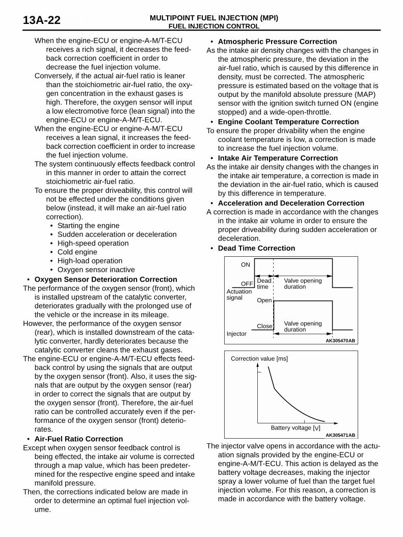
However, the volume of air that is actually drawn into the engine will be influenced by factors such as the valve train or the intake air pulsations. Therefore, the actual air volume will be less than the calculated air volume at a given rate, in accordance with the engine speed and the intake manifold pressure.For this reason, the calculated intake air volume is corrected by a map value, which has been predeter-mined for the respective engine speed and intake manifold pressure, so that it will be equal to the actual intake air volume.Dividing the intake air volume after the correction into four parts will yield the actual intake air volume per cylinder per cycle.
INJECTOR ACTUATION DURATION CORRECTIONAn oxygen sensor feedback correction or an air-fuel ratio correction is made after the basic injector actua-tion duration has been determined.
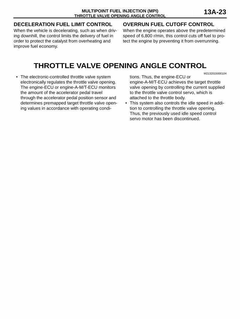
• Oxygen Sensor Feedback CorrectionDuring normal driving, the injector actuation duration
is corrected in accordance with the oxygen sen-sor signals in order to attain the stoichiometric air-fuel ratio in which the reduction rate of the three-way catalyst is at the optimum level.Operation
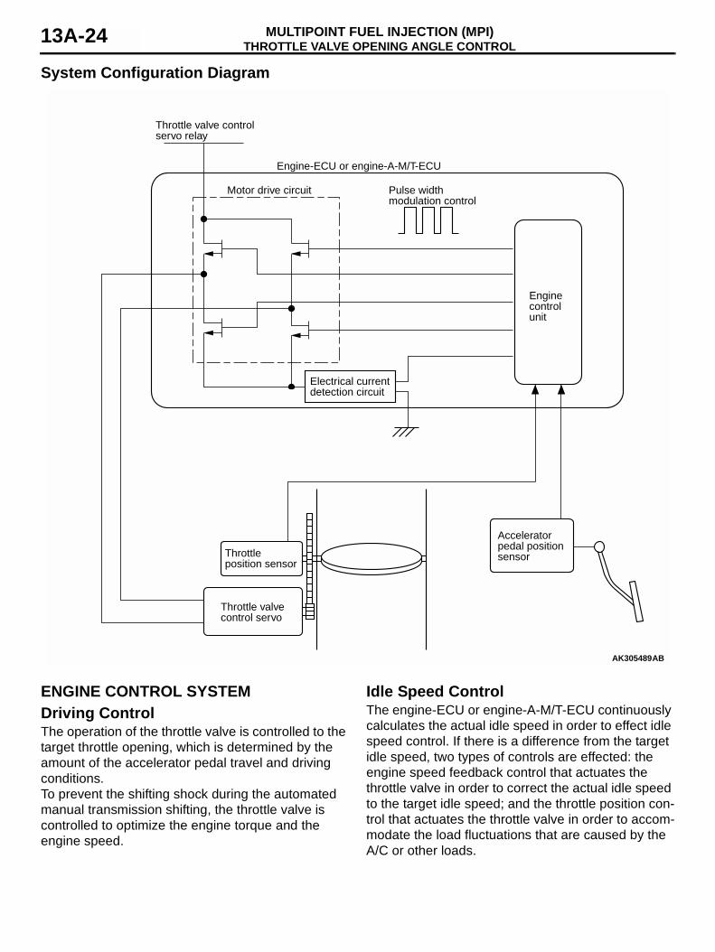
If the actual air-fuel ratio is richer than the stoichi-ometric air-fuel ratio, the oxygen concentra-tion in the exhaust gases is low. Therefore, the oxygen sensor will input a high electromo-tive force (rich signal) into the engine-ECU or engine-A-M/T-ECU.
AK305533
Ga = V = V RTP
Ga : Intake air volume [kg/cycle]
V : Stroke capacity [m3]
P : Average intake manifold pressure per cycle [kg/m3]
T : Intake air temperature [K]
R : Gas constant (29.27 for air) [kgm/kgK]: Specific weight of intake air [kg/m3]
AK305486Engine speed [r/min]
AE
Intake manifold pressure [kPa]
Correctioncoefficient
AK305463
0ABStoichiometric air-fuel ratio
100
50
HC
CO
NOx
Reduction rate [%]
AK305469AB
Stoichiometricair-fuel ratio
Lean
Engine air-fuel ratio
Oxygen sensor electromotive force
Fuel injectionvolume
Rich
High
LowComparativevoltage
Increase
Decrease
FUEL INJECTION CONTROLMULTIPOINT FUEL INJECTION (MPI)13A-22
When the engine-ECU or engine-A-M/T-ECU receives a rich signal, it decreases the feed-back correction coefficient in order to decrease the fuel injection volume.
Conversely, if the actual air-fuel ratio is leaner than the stoichiometric air-fuel ratio, the oxy-gen concentration in the exhaust gases is high. Therefore, the oxygen sensor will input a low electromotive force (lean signal) into the engine-ECU or engine-A-M/T-ECU.
When the engine-ECU or engine-A-M/T-ECU receives a lean signal, it increases the feed-back correction coefficient in order to increase the fuel injection volume.
The system continuously effects feedback control in this manner in order to attain the correct stoichiometric air-fuel ratio.
To ensure the proper driveability, this control will not be effected under the conditions given below (instead, it will make an air-fuel ratio correction).• Starting the engine• Sudden acceleration or deceleration• High-speed operation• Cold engine• High-load operation• Oxygen sensor inactive
• Oxygen Sensor Deterioration CorrectionThe performance of the oxygen sensor (front), which
is installed upstream of the catalytic converter, deteriorates gradually with the prolonged use of the vehicle or the increase in its mileage.
However, the performance of the oxygen sensor (rear), which is installed downstream of the cata-lytic converter, hardly deteriorates because the catalytic converter cleans the exhaust gases.
The engine-ECU or engine-A-M/T-ECU effects feed-back control by using the signals that are output by the oxygen sensor (front). Also, it uses the sig-nals that are output by the oxygen sensor (rear) in order to correct the signals that are output by the oxygen sensor (front). Therefore, the air-fuel ratio can be controlled accurately even if the per-formance of the oxygen sensor (front) deterio-rates.
• Air-Fuel Ratio CorrectionExcept when oxygen sensor feedback control is
being effected, the intake air volume is corrected through a map value, which has been predeter-mined for the respective engine speed and intake manifold pressure.
Then, the corrections indicated below are made in order to determine an optimal fuel injection vol-ume.
• Atmospheric Pressure CorrectionAs the intake air density changes with the changes in
the atmospheric pressure, the deviation in the air-fuel ratio, which is caused by this difference in density, must be corrected. The atmospheric pressure is estimated based on the voltage that is output by the manifold absolute pressure (MAP) sensor with the ignition switch turned ON (engine stopped) and a wide-open-throttle.
• Engine Coolant Temperature CorrectionTo ensure the proper drivability when the engine
coolant temperature is low, a correction is made to increase the fuel injection volume.
• Intake Air Temperature CorrectionAs the intake air density changes with the changes in
the intake air temperature, a correction is made in the deviation in the air-fuel ratio, which is caused by this difference in temperature.
• Acceleration and Deceleration CorrectionA correction is made in accordance with the changes
in the intake air volume in order to ensure the proper driveability during sudden acceleration or deceleration.
• Dead Time Correction
The injector valve opens in accordance with the actu-ation signals provided by the engine-ECU or engine-A-M/T-ECU. This action is delayed as the battery voltage decreases, making the injector spray a lower volume of fuel than the target fuel injection volume. For this reason, a correction is made in accordance with the battery voltage.
AK305470AB
Valve openingduration
Valve openingduration
Actuationsignal
Injector
Deadtime
Open
Close
ON
OFF
AK305471ABBattery voltage [V]
Correction value [ms]
THROTTLE VALVE OPENING ANGLE CONTROLMULTIPOINT FUEL INJECTION (MPI) 13A-23
DECELERATION FUEL LIMIT CONTROLWhen the vehicle is decelerating, such as when driv-ing downhill, the control limits the delivery of fuel in order to protect the catalyst from overheating and improve fuel economy.
OVERRUN FUEL CUTOFF CONTROLWhen the engine operates above the predetermined speed of 6,800 r/min, this control cuts off fuel to pro-tect the engine by preventing it from overrunning.
THROTTLE VALVE OPENING ANGLE CONTROLM2132015000104
• The electronic-controlled throttle valve system electronically regulates the throttle valve opening. The engine-ECU or engine-A-M/T-ECU monitors the amount of the accelerator pedal travel through the accelerator pedal position sensor and determines premapped target throttle valve open-ing values in accordance with operating condi-
tions. Thus, the engine-ECU or engine-A-M/T-ECU achieves the target throttle valve opening by controlling the current supplied to the throttle valve control servo, which is attached to the throttle body.
• This system also controls the idle speed in addi-tion to controlling the throttle valve opening. Thus, the previously used idle speed control servo motor has been discontinued.
THROTTLE VALVE OPENING ANGLE CONTROLMULTIPOINT FUEL INJECTION (MPI)13A-24
System Configuration Diagram
ENGINE CONTROL SYSTEMDriving ControlThe operation of the throttle valve is controlled to the target throttle opening, which is determined by the amount of the accelerator pedal travel and driving conditions.To prevent the shifting shock during the automated manual transmission shifting, the throttle valve is controlled to optimize the engine torque and the engine speed.
Idle Speed ControlThe engine-ECU or engine-A-M/T-ECU continuously calculates the actual idle speed in order to effect idle speed control. If there is a difference from the target idle speed, two types of controls are effected: the engine speed feedback control that actuates the throttle valve in order to correct the actual idle speed to the target idle speed; and the throttle position con-trol that actuates the throttle valve in order to accom-modate the load fluctuations that are caused by the A/C or other loads.
AK305489
Throttle position sensor
Accelerator pedal positionsensor
Engine control unit
Pulse width modulation control
Engine-ECU or engine-A-M/T-ECU
Throttle valve control servo relay
Motor drive circuit
Electrical current detection circuit
Throttle valve control servo
AB
IGNITION TIMING AND DISTRIBUTION CONTROLMULTIPOINT FUEL INJECTION (MPI) 13A-25
Engine Speed Feedback ControlThis control regulates the volume of air that flows through the throttle valve by actuating the throttle valve, in order to maintain the engine at a prescribed target idle speed. An optimal target idle speed is set to suit every operating condition (such as whether the A/C switch is ON or OFF). The engine speed feedback control is effected only when the pre-scribed operating conditions are met, and the throttle valve position control is effected at all other times.
Throttle Valve Position ControlWhile the engine is operating at idle, the idle speed could change suddenly when the load that is applied to the engine changes, such as when the steering wheel is turned, the A/C switch is turned ON/OFF, or the shift lever is operated. Immediately after any of
these signals are detected, this control actuates the throttle valve until the target position is attained, in order to regulate the volume of air that flows through the throttle valve. Thus, the fluctuation of the engine speed is restrained.
Failsafe Control• If the engine-ECU or engine-A-M/T-ECU detects
a malfunction in the system, it illuminates the engine warning lamp. At the same time, the engine-ECU or engine-A-M/T-ECU reduces the engine output by restricting the throttle valve opening or by cutting off the fuel supply, or, it dis-ables the throttle valve control servo by cutting off the power to the throttle valve control servo relay.
• When the power to the throttle valve control servo relay is cut off, the throttle valve assumes a pre-scribed opening (to supply a volume of air that enables a minimum operation of the vehicle). Thus, this control enables the vehicle to be driven at a minimum level even if a malfunction occurs in the throttle control system.
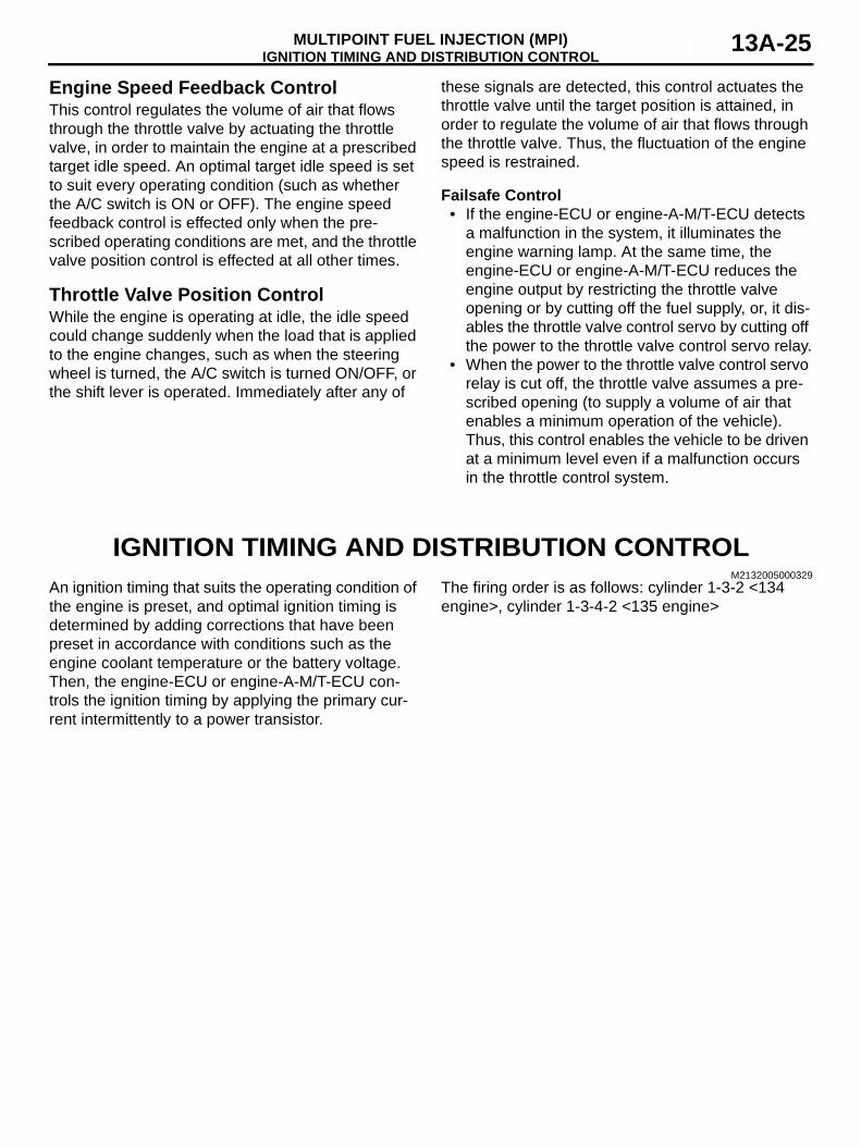
IGNITION TIMING AND DISTRIBUTION CONTROLM2132005000329
An ignition timing that suits the operating condition of the engine is preset, and optimal ignition timing is determined by adding corrections that have been preset in accordance with conditions such as the engine coolant temperature or the battery voltage. Then, the engine-ECU or engine-A-M/T-ECU con-trols the ignition timing by applying the primary cur-rent intermittently to a power transistor.
The firing order is as follows: cylinder 1-3-2 <134 engine>, cylinder 1-3-4-2 <135 engine>
IGNITION TIMING AND DISTRIBUTION CONTROLMULTIPOINT FUEL INJECTION (MPI)13A-26
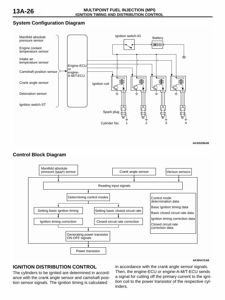
System Configuration Diagram
Control Block Diagram
IGNITION DISTRIBUTION CONTROLThe cylinders to be ignited are determined in accord-ance with the crank angle sensor and camshaft posi-tion sensor signals. The ignition timing is calculated
in accordance with the crank angle sensor signals. Then, the engine-ECU or engine-A-M/T-ECU sends a signal for cutting off the primary current to the igni-tion coil to the power transistor of the respective cyl-inders.
AK305298
Ignition switch-IG
Ignition coil
Battery
Spark plug
Cylinder No. 1 2 3 4
Intake air temperature sensor
Engine coolant temperature sensor
Camshaft position sensor
Crank angle sensor
Detonation sensor
Ignition switch-ST
AB
Manifold absolutepressure sensor
Engine-ECUorengine-A-M/T-ECU
AK305472
Closed circuit rate correction data
Generating power transistorON-OFF signals
Closed circuit rate correctionIgnition timing correction
Determining control modes
Reading input signals
Setting basic ignition timing
Power transistor
Setting basic closed circuit rate
Manifold absolute pressure (MAP) sensor Crank angle sensor Various sensors
AB
Control mode determination data
Basic ignition timing data
Basic closed circuit rate data
Ignition timing correction data
IGNITION TIMING AND DISTRIBUTION CONTROLMULTIPOINT FUEL INJECTION (MPI) 13A-27
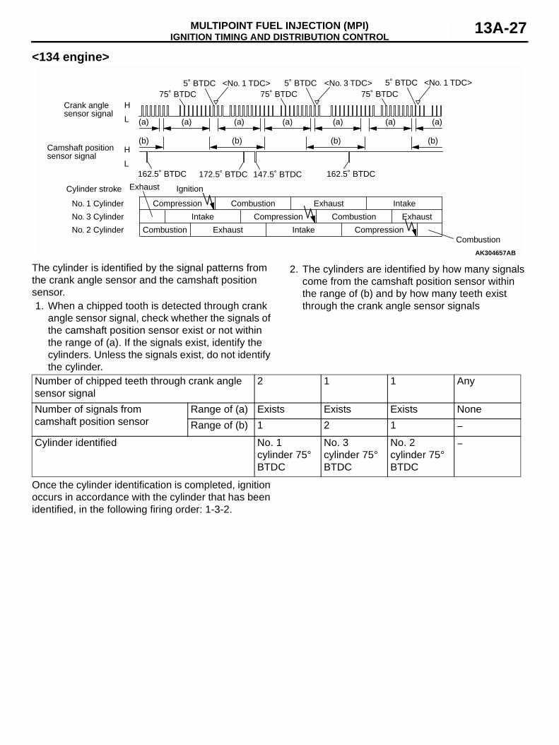
<134 engine>
The cylinder is identified by the signal patterns from the crank angle sensor and the camshaft position sensor.1. When a chipped tooth is detected through crank
angle sensor signal, check whether the signals of the camshaft position sensor exist or not within the range of (a). If the signals exist, identify the cylinders. Unless the signals exist, do not identify the cylinder.
2. The cylinders are identified by how many signals come from the camshaft position sensor within the range of (b) and by how many teeth exist through the crank angle sensor signals
Once the cylinder identification is completed, ignition occurs in accordance with the cylinder that has been identified, in the following firing order: 1-3-2.
AK304657AB
<No. 1 TDC>
H
L
H
L
Crank anglesensor signal
Camshaft position sensor signal
Cylinder stroke
No. 1 Cylinder
No. 3 Cylinder
No. 2 Cylinder
Intake
Intake
Ignition
Compression
Compression
Compression
Combustion
Combustion
Combustion
Exhaust
Exhaust
Exhaust
Intake
Exhaust
Combustion
5˚ BTDC75˚ BTDC
(a) (a) (a) (a) (a) (a) (a)
(b) (b) (b)(b)
<No. 3 TDC>5˚ BTDC75˚ BTDC
<No. 1 TDC>5˚ BTDC75˚ BTDC
162.5˚ BTDC 147.5˚ BTDC172.5˚ BTDC 162.5˚ BTDC
Number of chipped teeth through crank angle sensor signal
2 1 1 Any
Number of signals from camshaft position sensor
Range of (a) Exists Exists Exists NoneRange of (b) 1 2 1 −
Cylinder identified No. 1 cylinder 75° BTDC
No. 3 cylinder 75° BTDC
No. 2 cylinder 75° BTDC
−
IGNITION TIMING AND DISTRIBUTION CONTROLMULTIPOINT FUEL INJECTION (MPI)13A-28
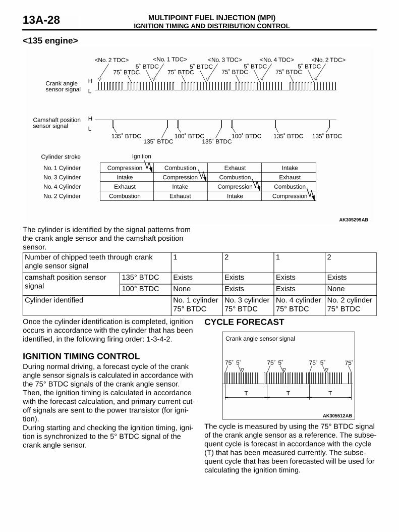
<135 engine>
The cylinder is identified by the signal patterns from the crank angle sensor and the camshaft position sensor.
Once the cylinder identification is completed, ignition occurs in accordance with the cylinder that has been identified, in the following firing order: 1-3-4-2.
IGNITION TIMING CONTROLDuring normal driving, a forecast cycle of the crank angle sensor signals is calculated in accordance with the 75° BTDC signals of the crank angle sensor. Then, the ignition timing is calculated in accordance with the forecast calculation, and primary current cut-off signals are sent to the power transistor (for igni-tion).During starting and checking the ignition timing, igni-tion is synchronized to the 5° BTDC signal of the crank angle sensor.
CYCLE FORECAST
The cycle is measured by using the 75° BTDC signal of the crank angle sensor as a reference. The subse-quent cycle is forecast in accordance with the cycle (T) that has been measured currently. The subse-quent cycle that has been forecasted will be used for calculating the ignition timing.
AK305299AB
<No. 2 TDC>
H
L
H
L
<No. 1 TDC> <No. 3 TDC> <No. 4 TDC> <No. 2 TDC>
Crank anglesensor signal
Camshaft positionsensor signal
Cylinder stroke
No. 1 Cylinder
No. 3 Cylinder
No. 4 Cylinder
No. 2 Cylinder
Intake
Intake
Intake
Ignition
Compression
Compression
Compression
Compression
Combustion
Combustion
Combustion
Combustion
Exhaust
Exhaust
Exhaust
Exhaust
Intake
5˚ BTDC75˚ BTDC
135˚ BTDC
75˚ BTDC5˚ BTDC
75˚ BTDC5˚ BTDC
75˚ BTDC5˚ BTDC
100˚ BTDC135˚ BTDC
100˚ BTDC135˚ BTDC
135˚ BTDC 135˚ BTDC
Number of chipped teeth through crank angle sensor signal
1 2 1 2
camshaft position sensor signal
135° BTDC Exists Exists Exists Exists100° BTDC None Exists Exists None
Cylinder identified No. 1 cylinder 75° BTDC
No. 3 cylinder 75° BTDC
No. 4 cylinder 75° BTDC
No. 2 cylinder 75° BTDC
AK200601AK305512
T T T
AB
75˚ 5˚ 75˚ 5˚ 75˚ 5˚ 75˚
Crank angle sensor signal
IGNITION TIMING AND DISTRIBUTION CONTROLMULTIPOINT FUEL INJECTION (MPI) 13A-29
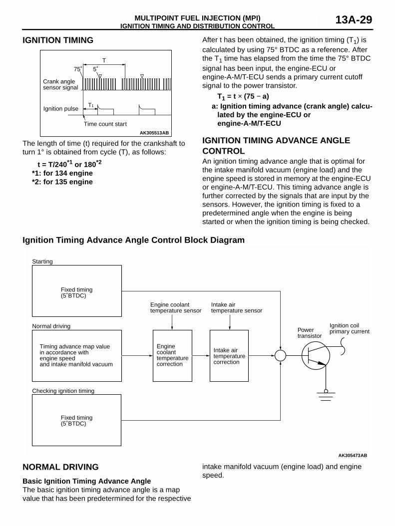
IGNITION TIMING
The length of time (t) required for the crankshaft to turn 1° is obtained from cycle (T), as follows:
t = T/240*1 or 180*2
*1: for 134 engine*2: for 135 engine
After t has been obtained, the ignition timing (T1) is calculated by using 75° BTDC as a reference. After the T1 time has elapsed from the time the 75° BTDC signal has been input, the engine-ECU or engine-A-M/T-ECU sends a primary current cutoff signal to the power transistor.
T1 = t × (75 − a)a: Ignition timing advance (crank angle) calcu-
lated by the engine-ECU or engine-A-M/T-ECU
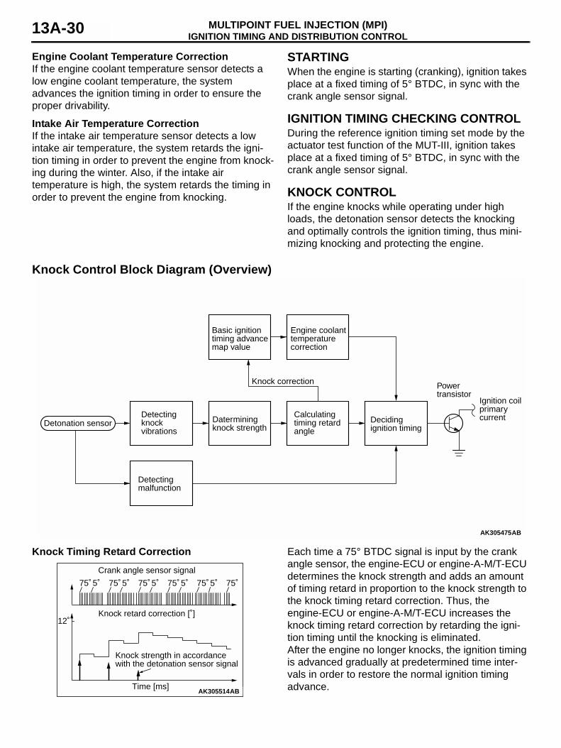
IGNITION TIMING ADVANCE ANGLE CONTROLAn ignition timing advance angle that is optimal for the intake manifold vacuum (engine load) and the engine speed is stored in memory at the engine-ECU or engine-A-M/T-ECU. This timing advance angle is further corrected by the signals that are input by the sensors. However, the ignition timing is fixed to a predetermined angle when the engine is being started or when the ignition timing is being checked.
Ignition Timing Advance Angle Control Block Diagram
NORMAL DRIVINGBasic Ignition Timing Advance AngleThe basic ignition timing advance angle is a map value that has been predetermined for the respective
intake manifold vacuum (engine load) and engine speed.
AK200601AK305513
T
AB
75˚ 5˚
Crank anglesensor signal
T1Ignition pulse
Time count start
AK305473
Powertransistor
Intake air temperaturecorrection
Enginecoolanttemperaturecorrection
Intake air temperature sensor
Engine coolanttemperature sensor
Starting
Fixed timing (5˚BTDC)
Fixed timing (5˚BTDC)
Timing advance map value in accordance with engine speed and intake manifold vacuum
Normal driving
Checking ignition timing
Ignition coilprimary current
AB
IGNITION TIMING AND DISTRIBUTION CONTROLMULTIPOINT FUEL INJECTION (MPI)13A-30
Engine Coolant Temperature CorrectionIf the engine coolant temperature sensor detects a low engine coolant temperature, the system advances the ignition timing in order to ensure the proper drivability.
Intake Air Temperature CorrectionIf the intake air temperature sensor detects a low intake air temperature, the system retards the igni-tion timing in order to prevent the engine from knock-ing during the winter. Also, if the intake air temperature is high, the system retards the timing in order to prevent the engine from knocking.
STARTINGWhen the engine is starting (cranking), ignition takes place at a fixed timing of 5° BTDC, in sync with the crank angle sensor signal.
IGNITION TIMING CHECKING CONTROLDuring the reference ignition timing set mode by the actuator test function of the MUT-III, ignition takes place at a fixed timing of 5° BTDC, in sync with the crank angle sensor signal.
KNOCK CONTROLIf the engine knocks while operating under high loads, the detonation sensor detects the knocking and optimally controls the ignition timing, thus mini-mizing knocking and protecting the engine.
Knock Control Block Diagram (Overview)
Knock Timing Retard Correction Each time a 75° BTDC signal is input by the crank angle sensor, the engine-ECU or engine-A-M/T-ECU determines the knock strength and adds an amount of timing retard in proportion to the knock strength to the knock timing retard correction. Thus, the engine-ECU or engine-A-M/T-ECU increases the knock timing retard correction by retarding the igni-tion timing until the knocking is eliminated.After the engine no longer knocks, the ignition timing is advanced gradually at predetermined time inter-vals in order to restore the normal ignition timing advance.
AK305475
Knock correction
Detectingknockvibrations
Datermining knock strength
Calculatingtiming retardangle
Decidingignition timing
Power transistor
Detectingmalfunction
Basic ignition timing advancemap value
Engine coolanttemperaturecorrection
Ignition coilprimarycurrent
Detonation sensor
AB
AK305514
Crank angle sensor signal
Time [ms]
12˚
75˚ 5˚ 75˚ 5˚ 75˚ 5˚ 75˚ 5˚ 75˚ 5˚ 75˚
Knock retard correction [˚]
AB
Knock strength in accordance with the detonation sensor signal
MIVEC (Mitsubishi Innovative Valve timing Electronic Control system)MULTIPOINT FUEL INJECTION (MPI) 13A-31
If there is an open or short circuit in the wiring har-ness for the detonation sensor, the engine operates at an ignition timing that corresponds to the standard petrol, in order to prevent the engine from knocking.
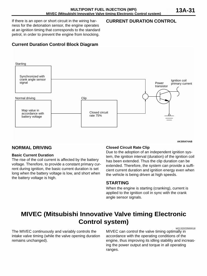
CURRENT DURATION CONTROL
Current Duration Control Block Diagram
NORMAL DRIVINGBasic Current DurationThe rise of the coil current is affected by the battery voltage. Therefore, to provide a constant primary cur-rent during ignition, the basic current duration is set long when the battery voltage is low, and short when the battery voltage is high.
Closed Circuit Rate ClipDue to the adoption of an independent ignition sys-tem, the ignition interval (duration) of the ignition coil has been extended. Thus the clip duration can be extended. Therefore, the system can provide a suffi-cient current duration and ignition energy even when the vehicle is being driven at high speeds.
STARTINGWhen the engine is starting (cranking), current is applied to the ignition coil in sync with the crank angle sensor signals.
MIVEC (Mitsubishi Innovative Valve timing Electronic Control system)
M2132023500018The MIVEC continuously and variably controls the intake valve timing (while the valve opening duration remains unchanged).
MIVEC can control the valve timing optimally in accordance with the operating conditions of the engine, thus improving its idling stability and increas-ing the power output and torque in all operating ranges.
AK305474
Powertransistor
Starting
Synchronized withcrank angle sensor signal
Map value in accordance with battery voltage
Normal driving
Closed circuitrate 75%
Clip
Ignition coilprimary current
AB
MIVEC (Mitsubishi Innovative Valve timing Electronic Control system)MULTIPOINT FUEL INJECTION (MPI)13A-32
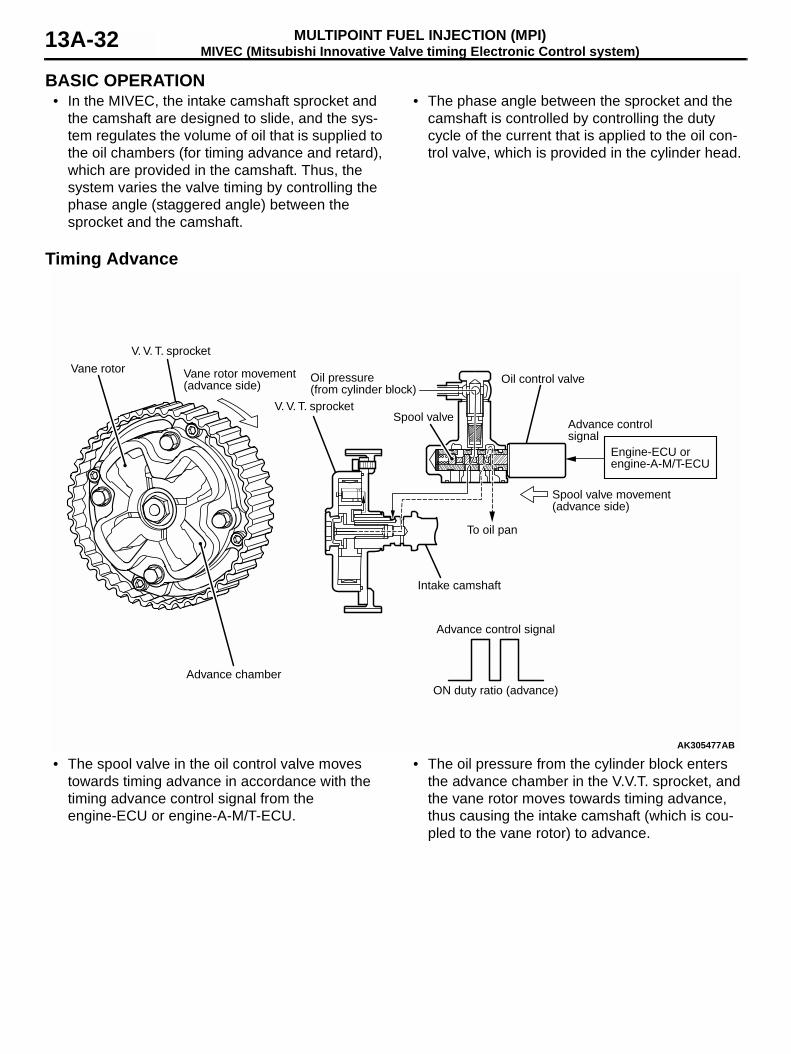
BASIC OPERATION• In the MIVEC, the intake camshaft sprocket and
the camshaft are designed to slide, and the sys-tem regulates the volume of oil that is supplied to the oil chambers (for timing advance and retard), which are provided in the camshaft. Thus, the system varies the valve timing by controlling the phase angle (staggered angle) between the sprocket and the camshaft.
• The phase angle between the sprocket and the camshaft is controlled by controlling the duty cycle of the current that is applied to the oil con-trol valve, which is provided in the cylinder head.
Timing Advance
• The spool valve in the oil control valve moves towards timing advance in accordance with the timing advance control signal from the engine-ECU or engine-A-M/T-ECU.
• The oil pressure from the cylinder block enters the advance chamber in the V.V.T. sprocket, and the vane rotor moves towards timing advance, thus causing the intake camshaft (which is cou-pled to the vane rotor) to advance.
AK305477
Engine-ECU or engine-A-M/T-ECU
Vane rotor
V. V. T. sprocket
Vane rotor movement(advance side)
Advance chamber
V. V. T. sprocket
Oil pressure(from cylinder block)
Spool valve
Intake camshaft
To oil pan
Spool valve movement(advance side)
Oil control valve
Advance control signal
Advance control signal
ON duty ratio (advance)
AB
MIVEC (Mitsubishi Innovative Valve timing Electronic Control system)MULTIPOINT FUEL INJECTION (MPI) 13A-33
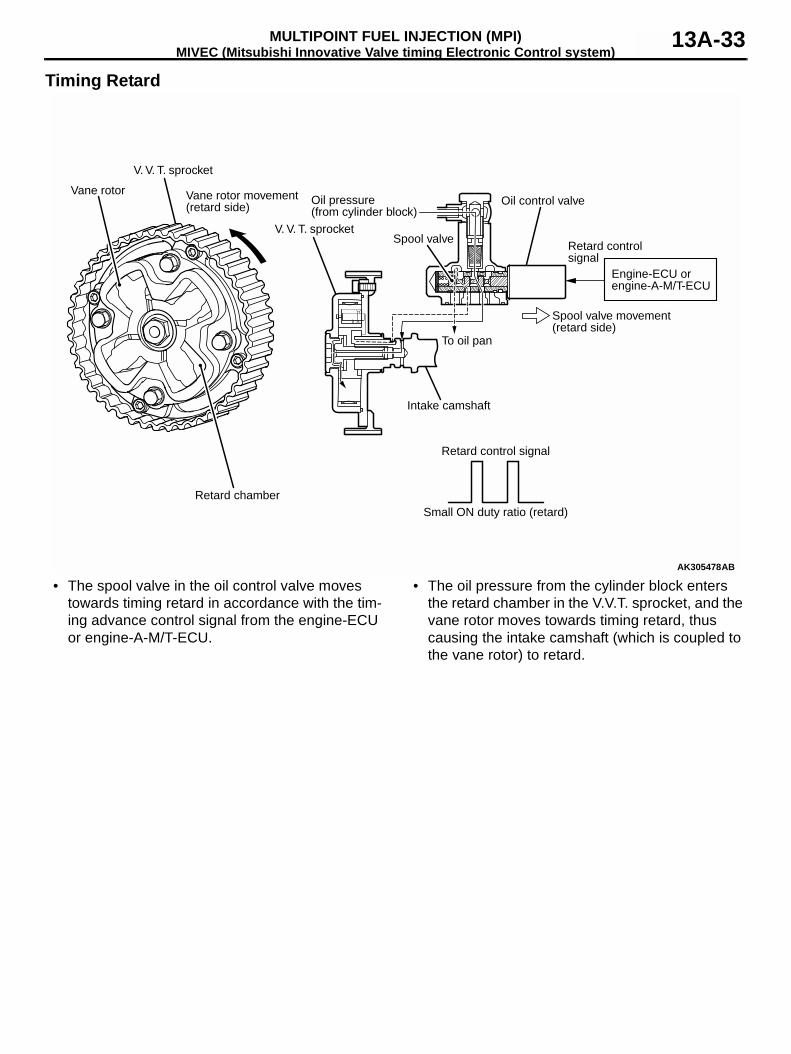
Timing Retard
• The spool valve in the oil control valve moves towards timing retard in accordance with the tim-ing advance control signal from the engine-ECU or engine-A-M/T-ECU.
• The oil pressure from the cylinder block enters the retard chamber in the V.V.T. sprocket, and the vane rotor moves towards timing retard, thus causing the intake camshaft (which is coupled to the vane rotor) to retard.
AK305478
Engine-ECU or engine-A-M/T-ECU
Vane rotor
V. V. T. sprocket
Vane rotor movement(retard side)
Retard chamber
V. V. T. sprocket
Oil pressure(from cylinder block)
Spool valve
Intake camshaft
To oil pan
Spool valve movement(retard side)
Oil control valve
Retard control signal
Retard control signal
Small ON duty ratio (retard)
AB
MIVEC (Mitsubishi Innovative Valve timing Electronic Control system)MULTIPOINT FUEL INJECTION (MPI)13A-34
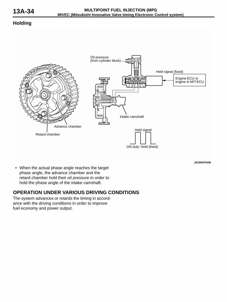
Holding
• When the actual phase angle reaches the target phase angle, the advance chamber and the retard chamber hold their oil pressure in order to hold the phase angle of the intake camshaft.
OPERATION UNDER VARIOUS DRIVING CONDITIONSThe system advances or retards the timing in accord-ance with the driving conditions in order to improve fuel economy and power output.
AK305479
Engine-ECU or engine-A-M/T-ECU
Oil pressure(from cylinder block)
Intake camshaft
Held signal (fixed)
Held signal
ON duty: Held (fixed)
AB
Retard chamber
Advance chamber
MIVEC (Mitsubishi Innovative Valve timing Electronic Control system)MULTIPOINT FUEL INJECTION (MPI) 13A-35
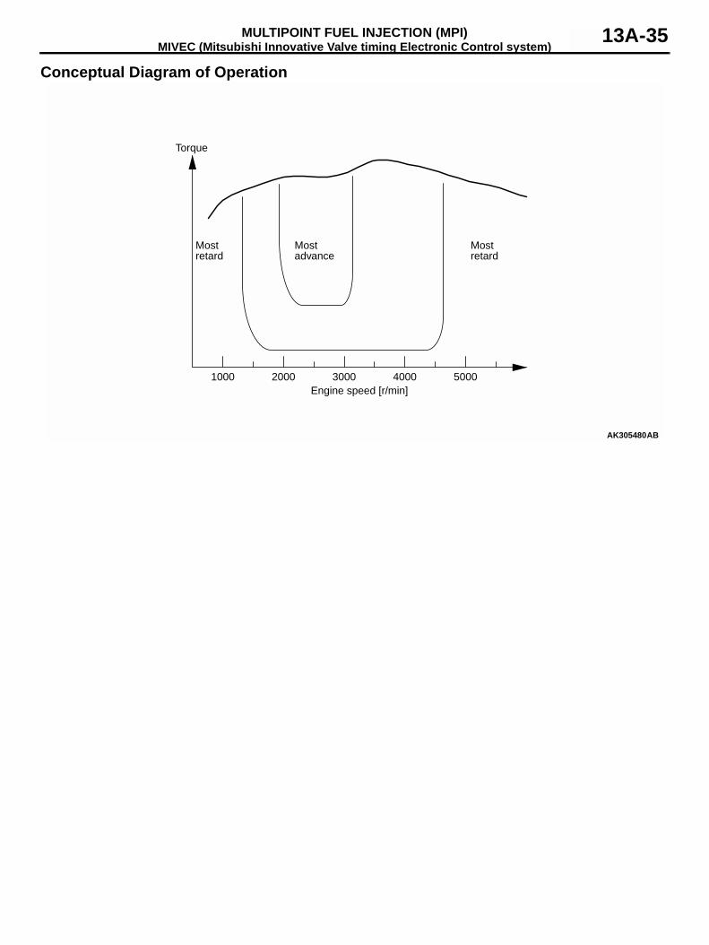
Conceptual Diagram of Operation
AK305480
Torque
Most retard
Most retard
Most advance
1000 2000 3000 4000 5000Engine speed [r/min]
AB
MIVEC (Mitsubishi Innovative Valve timing Electronic Control system)MULTIPOINT FUEL INJECTION (MPI)13A-36
OIL CONTROL VALVE CONTROL• The engine-ECU or engine-A-M/T-ECU assesses
the driving conditions by detecting the signals provided by various sensors, and sends duty cycle signals to the oil control valve in accord-ance with the driving conditions, in order to con-trol the position of the spool valve.
• In the oil control valve, the oil pressure is applied to the retard chamber or the advance chamber, in order to continuously vary the phase of the intake camshaft.
• When the engine is stopped, the engine-ECU or engine-A-M/T-ECU turns OFF the duty cycle sig-nals, and applies a constant oil pressure to the retard chamber in order to hold the spool valve in the most retarded position.
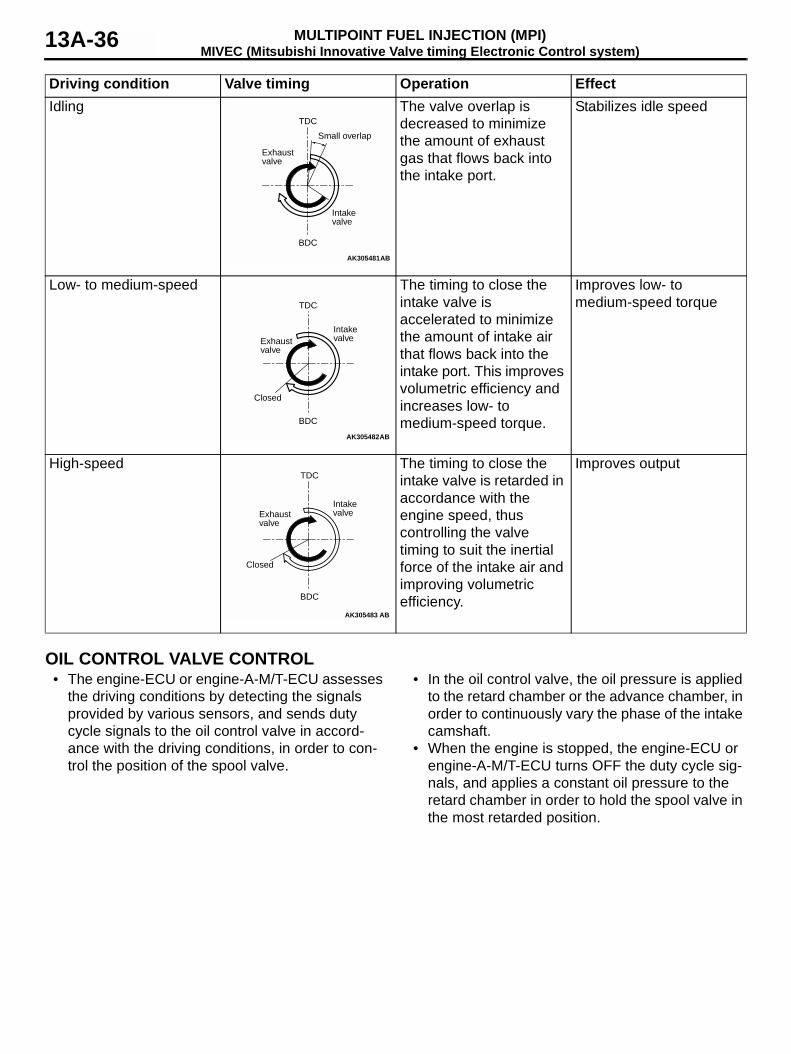
Driving condition Valve timing Operation EffectIdling The valve overlap is
decreased to minimize the amount of exhaust gas that flows back into the intake port.
Stabilizes idle speed
Low- to medium-speed The timing to close the intake valve is accelerated to minimize the amount of intake air that flows back into the intake port. This improves volumetric efficiency and increases low- to medium-speed torque.
Improves low- to medium-speed torque
High-speed The timing to close the intake valve is retarded in accordance with the engine speed, thus controlling the valve timing to suit the inertial force of the intake air and improving volumetric efficiency.
Improves output
AK305481
Small overlap
TDC
BDC
Intakevalve
Exhaustvalve
AB
AK305482
TDC
BDC
IntakevalveExhaust
valve
Closed
AB
AK305483
TDC
BDC
IntakevalveExhaust
valve
Closed
AB
MIVEC (Mitsubishi Innovative Valve timing Electronic Control system)MULTIPOINT FUEL INJECTION (MPI) 13A-37
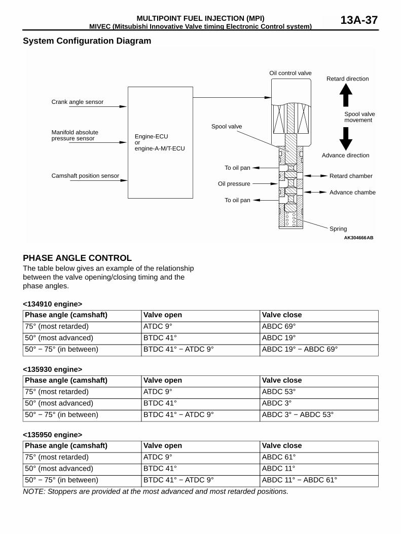
System Configuration Diagram
PHASE ANGLE CONTROLThe table below gives an example of the relationship between the valve opening/closing timing and the phase angles.
<134910 engine>
<135930 engine>
<135950 engine>
NOTE: Stoppers are provided at the most advanced and most retarded positions.
AK304666AB
Engine-ECUorengine-A-M/T-ECU
Spool valve
Retard chamber
Advance chambe
Spring
Advance direction
Spool valvemovement
Retard directionOil control valve
To oil pan
To oil pan
Oil pressure
Crank angle sensor
Manifold absolutepressure sensor
Camshaft position sensor
Phase angle (camshaft) Valve open Valve close75° (most retarded) ATDC 9° ABDC 69°50° (most advanced) BTDC 41° ABDC 19°50° − 75° (in between) BTDC 41° − ATDC 9° ABDC 19° − ABDC 69°
Phase angle (camshaft) Valve open Valve close75° (most retarded) ATDC 9° ABDC 53°50° (most advanced) BTDC 41° ABDC 3°50° − 75° (in between) BTDC 41° − ATDC 9° ABDC 3° − ABDC 53°
Phase angle (camshaft) Valve open Valve close75° (most retarded) ATDC 9° ABDC 61°50° (most advanced) BTDC 41° ABDC 11°50° − 75° (in between) BTDC 41° − ATDC 9° ABDC 11° − ABDC 61°
MIVEC (Mitsubishi Innovative Valve timing Electronic Control system)MULTIPOINT FUEL INJECTION (MPI)13A-38
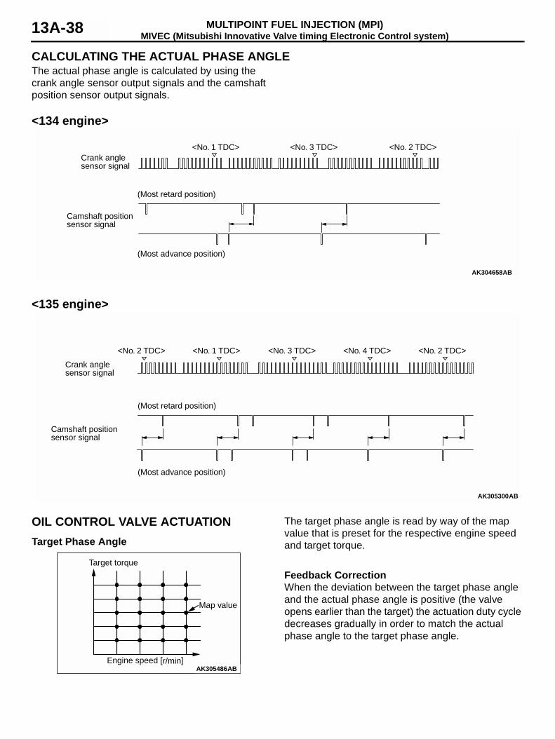
CALCULATING THE ACTUAL PHASE ANGLEThe actual phase angle is calculated by using the crank angle sensor output signals and the camshaft position sensor output signals.
<134 engine>
<135 engine>
OIL CONTROL VALVE ACTUATIONTarget Phase Angle
The target phase angle is read by way of the map value that is preset for the respective engine speed and target torque.
Feedback CorrectionWhen the deviation between the target phase angle and the actual phase angle is positive (the valve opens earlier than the target) the actuation duty cycle decreases gradually in order to match the actual phase angle to the target phase angle.
AK304658AB
<No. 1 TDC> <No. 3 TDC> <No. 2 TDC>Crank anglesensor signal
Camshaft position sensor signal
(Most retard position)
(Most advance position)
AK305300AB
<No. 2 TDC> <No. 1 TDC> <No. 3 TDC> <No. 4 TDC> <No. 2 TDC>
Crank anglesensor signal
Camshaft positionsensor signal
(Most retard position)
(Most advance position)
AK305486Engine speed [r/min]
Map value
Target torque
AB
POWER SUPPLY CONTROLMULTIPOINT FUEL INJECTION (MPI) 13A-39
On the other hand, if the deviation between the tar-get phase angle and the actual phase angle is nega-tive (the valve opens later than the target), the actuation duty cycle increases gradually in order to match the actual phase angle to the target phase angle.When the deviation between the target phase angle and the actual phase angle is practically zero, the oil control valve (after a learning correction) is actuated with the neutral duty cycle.
Actual Phase Angle CorrectionThe actual phase angle when the oil control valve is OFF is stored in learning memory as the minimum phase angle.When the oil control valve is OFF, the actual phase angle is compensated using the deviation between the phase angle 75° and the maximum phase angle (the sensor error), because the intake camshaft sprocket is accurately designed with phase angle 75°.
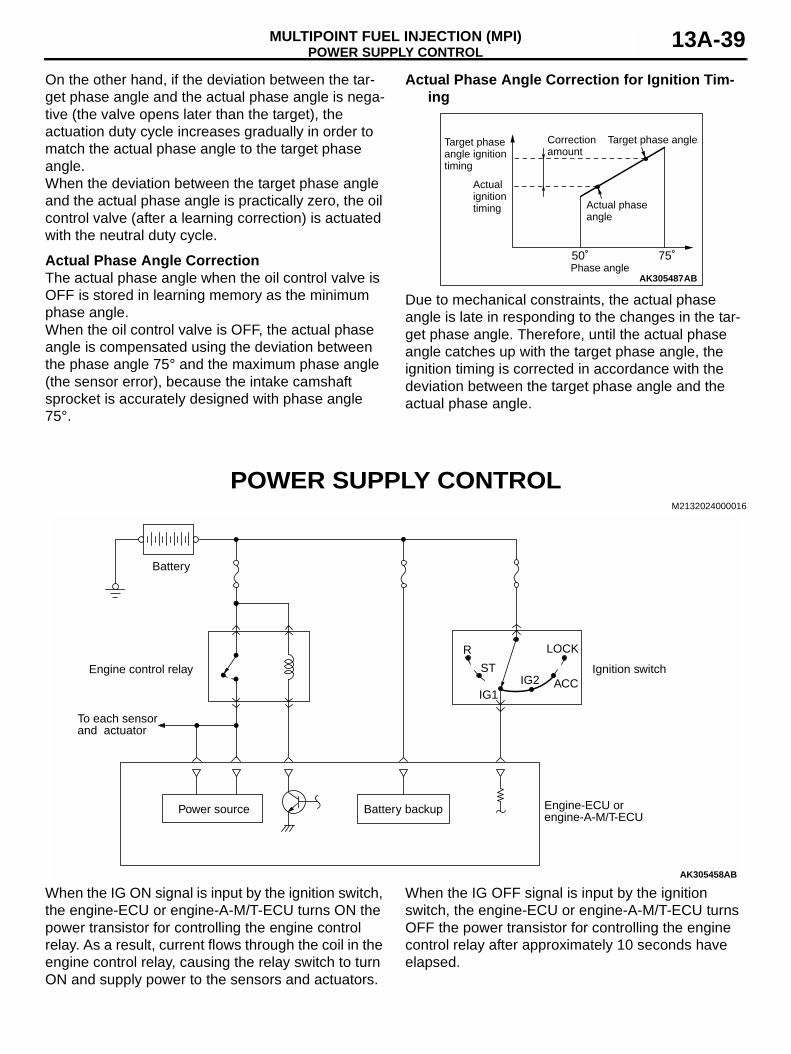
Actual Phase Angle Correction for Ignition Tim-ing
Due to mechanical constraints, the actual phase angle is late in responding to the changes in the tar-get phase angle. Therefore, until the actual phase angle catches up with the target phase angle, the ignition timing is corrected in accordance with the deviation between the target phase angle and the actual phase angle.
POWER SUPPLY CONTROL M2132024000016
When the IG ON signal is input by the ignition switch, the engine-ECU or engine-A-M/T-ECU turns ON the power transistor for controlling the engine control relay. As a result, current flows through the coil in the engine control relay, causing the relay switch to turn ON and supply power to the sensors and actuators.
When the IG OFF signal is input by the ignition switch, the engine-ECU or engine-A-M/T-ECU turns OFF the power transistor for controlling the engine control relay after approximately 10 seconds have elapsed.
AK305487
50˚ 75˚
ABPhase angle
Correctionamount
Target phase angle
Actual phaseangle
Actualignitiontiming
Target phase angle ignition timing
AK305458
Ignition switch
R
ST
IG1IG2 ACC
LOCK
Battery
Battery backup
Engine control relay
Engine-ECU orengine-A-M/T-ECU
Power source
AB
To each sensor and actuator
FUEL PUMP RELAY CONTROLMULTIPOINT FUEL INJECTION (MPI)13A-40
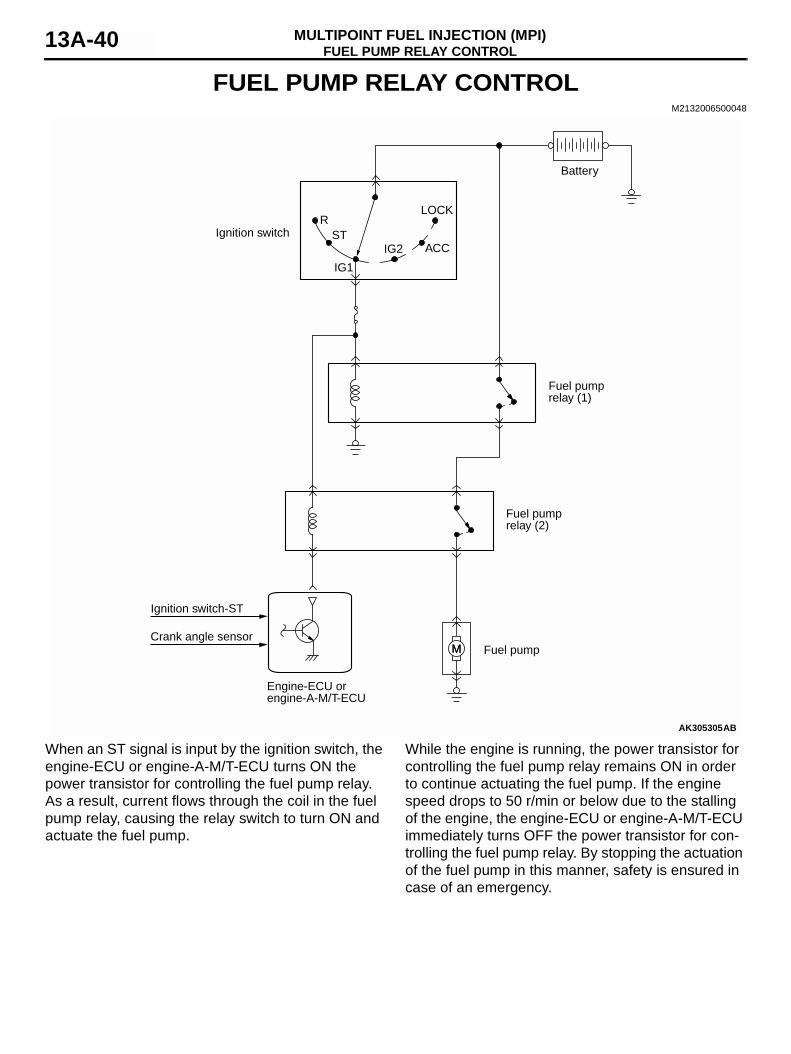
FUEL PUMP RELAY CONTROLM2132006500048
When an ST signal is input by the ignition switch, the engine-ECU or engine-A-M/T-ECU turns ON the power transistor for controlling the fuel pump relay. As a result, current flows through the coil in the fuel pump relay, causing the relay switch to turn ON and actuate the fuel pump.
While the engine is running, the power transistor for controlling the fuel pump relay remains ON in order to continue actuating the fuel pump. If the engine speed drops to 50 r/min or below due to the stalling of the engine, the engine-ECU or engine-A-M/T-ECU immediately turns OFF the power transistor for con-trolling the fuel pump relay. By stopping the actuation of the fuel pump in this manner, safety is ensured in case of an emergency.
AK305305
MM
Ignition switchR
ST
IG1
IG2 ACC
LOCK
Battery
Fuel pumprelay (1)
Engine-ECU orengine-A-M/T-ECU
Fuel pumprelay (2)
Fuel pump
AB
Ignition switch-ST
Crank angle sensor
OXYGEN SENSOR HEATER CONTROLMULTIPOINT FUEL INJECTION (MPI) 13A-41
OXYGEN SENSOR HEATER CONTROLM2132007000046
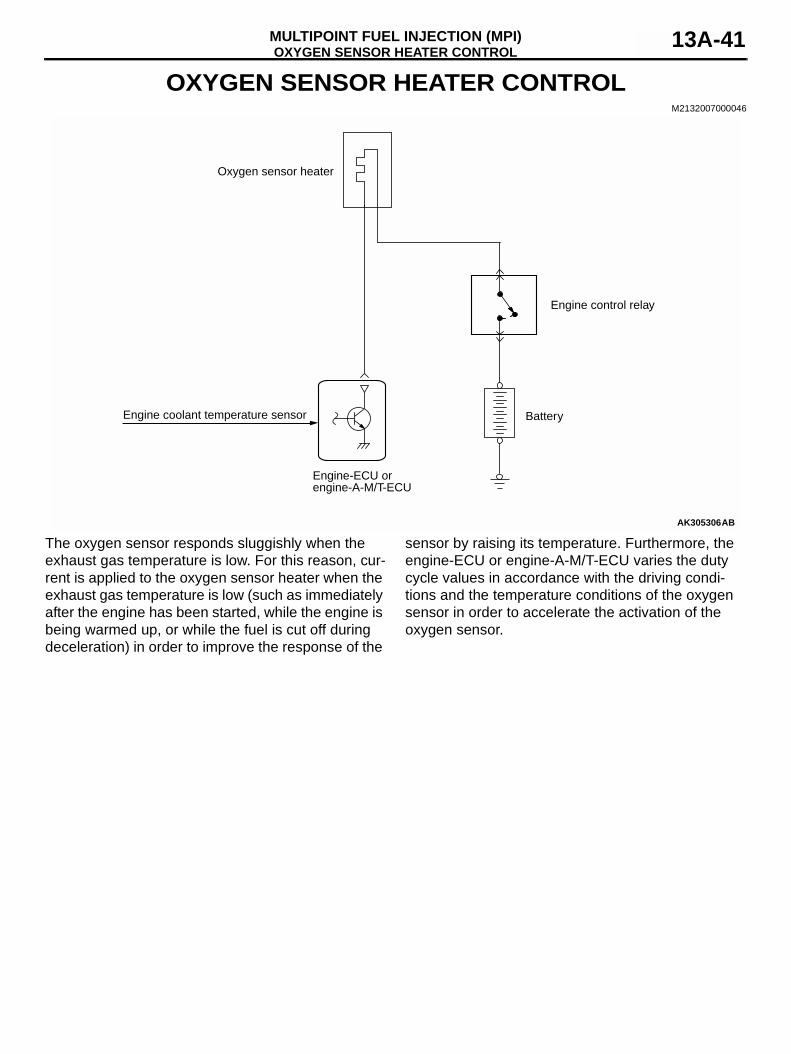
The oxygen sensor responds sluggishly when the exhaust gas temperature is low. For this reason, cur-rent is applied to the oxygen sensor heater when the exhaust gas temperature is low (such as immediately after the engine has been started, while the engine is being warmed up, or while the fuel is cut off during deceleration) in order to improve the response of the
sensor by raising its temperature. Furthermore, the engine-ECU or engine-A-M/T-ECU varies the duty cycle values in accordance with the driving condi-tions and the temperature conditions of the oxygen sensor in order to accelerate the activation of the oxygen sensor.
AK305306
Engine-ECU orengine-A-M/T-ECU
Battery
Oxygen sensor heater
AB
Engine coolant temperature sensor
Engine control relay
A/C COMPRESSOR CONTROLMULTIPOINT FUEL INJECTION (MPI)13A-42
A/C COMPRESSOR CONTROLM2132034500012
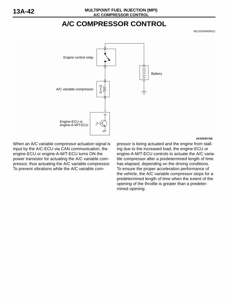
When an A/C variable compressor actuation signal is input by the A/C-ECU via CAN communication, the engine-ECU or engine-A-M/T-ECU turns ON the power transistor for actuating the A/C variable com-pressor, thus actuating the A/C variable compressor. To prevent vibrations while the A/C variable com-
pressor is being actuated and the engine from stall-ing due to the increased load, the engine-ECU or engine-A-M/T-ECU controls to actuate the A/C varia-ble compressor after a predetermined length of time has elapsed, depending on the driving conditions.To ensure the proper acceleration performance of the vehicle, the A/C variable compressor stops for a predetermined length of time when the extent of the opening of the throttle is greater than a predeter-mined opening.
AK305307
Engine control relay
A/C variable compressor
Engine-ECU orengine-A-M/T-ECU
Battery
AB
ALTERNATOR CONTROLMULTIPOINT FUEL INJECTION (MPI) 13A-43
ALTERNATOR CONTROLM2132025000019
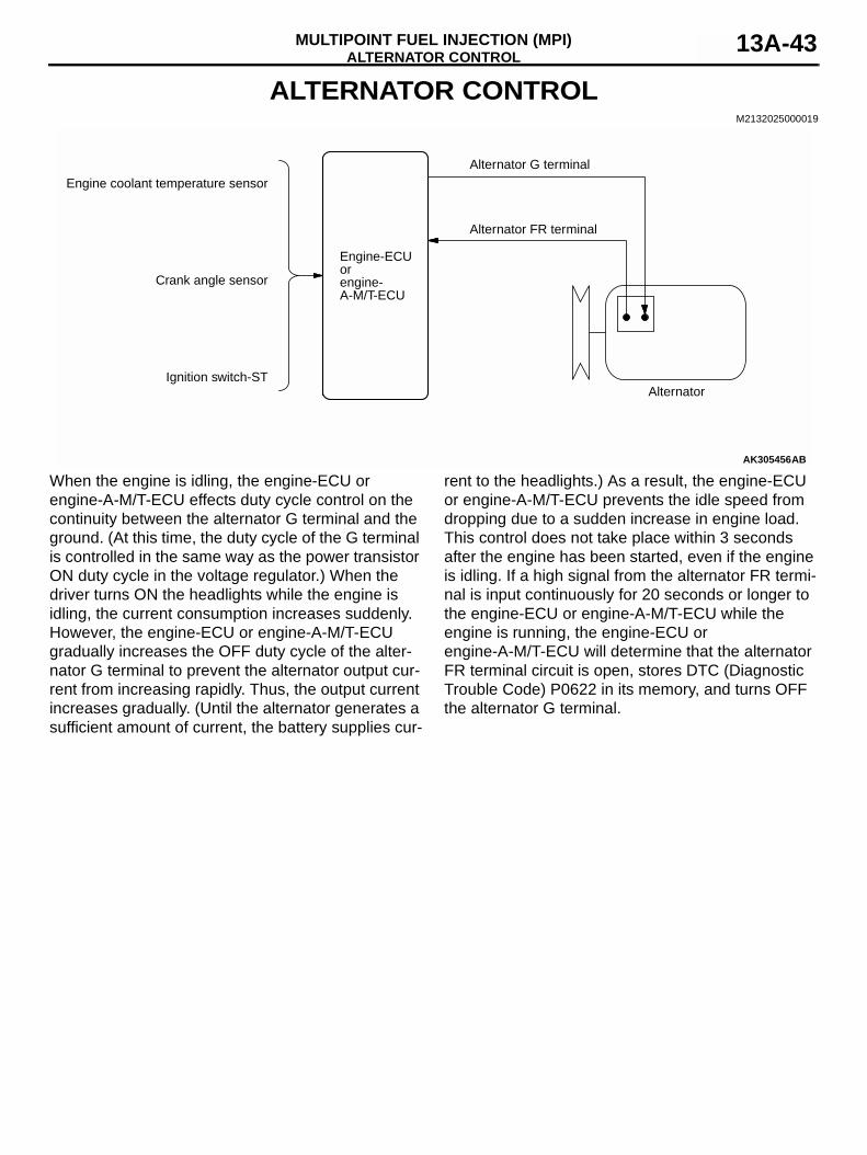
When the engine is idling, the engine-ECU or engine-A-M/T-ECU effects duty cycle control on the continuity between the alternator G terminal and the ground. (At this time, the duty cycle of the G terminal is controlled in the same way as the power transistor ON duty cycle in the voltage regulator.) When the driver turns ON the headlights while the engine is idling, the current consumption increases suddenly. However, the engine-ECU or engine-A-M/T-ECU gradually increases the OFF duty cycle of the alter-nator G terminal to prevent the alternator output cur-rent from increasing rapidly. Thus, the output current increases gradually. (Until the alternator generates a sufficient amount of current, the battery supplies cur-
rent to the headlights.) As a result, the engine-ECU or engine-A-M/T-ECU prevents the idle speed from dropping due to a sudden increase in engine load. This control does not take place within 3 seconds after the engine has been started, even if the engine is idling. If a high signal from the alternator FR termi-nal is input continuously for 20 seconds or longer to the engine-ECU or engine-A-M/T-ECU while the engine is running, the engine-ECU or engine-A-M/T-ECU will determine that the alternator FR terminal circuit is open, stores DTC (Diagnostic Trouble Code) P0622 in its memory, and turns OFF the alternator G terminal.
AK305456
Engine coolant temperature sensor
Alternator
Engine-ECUorengine-A-M/T-ECU
Crank angle sensor
Ignition switch-ST
AB
Alternator FR terminal
Alternator G terminal
STARTER RELAY CONTROLMULTIPOINT FUEL INJECTION (MPI)13A-44
STARTER RELAY CONTROLM2132025500014
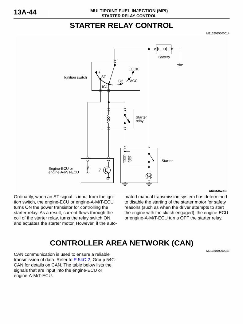
Ordinarily, when an ST signal is input from the igni-tion switch, the engine-ECU or engine-A-M/T-ECU turns ON the power transistor for controlling the starter relay. As a result, current flows through the coil of the starter relay, turns the relay switch ON, and actuates the starter motor. However, if the auto-
mated manual transmission system has determined to disable the starting of the starter motor for safety reasons (such as when the driver attempts to start the engine with the clutch engaged), the engine-ECU or engine-A-M/T-ECU turns OFF the starter relay.
CONTROLLER AREA NETWORK (CAN)M2132019000043
CAN communication is used to ensure a reliable transmission of data. Refer to P.54C-2, Group 54C - CAN for details on CAN. The table below lists the signals that are input into the engine-ECU or engine-A-M/T-ECU.
AK305457AK305457
Ignition switch
RST
IG1
IG2 ACC
LOCK
Battery
Starter
Starterrelay
Engine-ECU orengine-A-M/T-ECU
AB
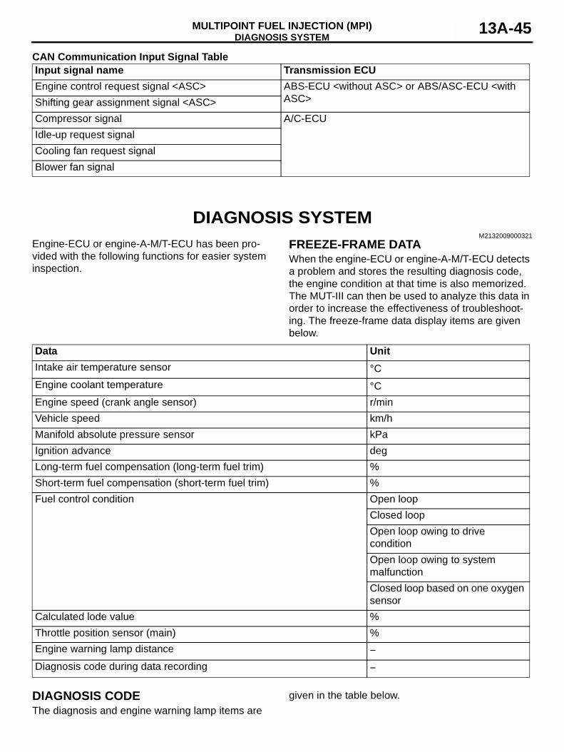
DIAGNOSIS SYSTEMMULTIPOINT FUEL INJECTION (MPI) 13A-45
CAN Communication Input Signal Table
DIAGNOSIS SYSTEMM2132009000321
Engine-ECU or engine-A-M/T-ECU has been pro-vided with the following functions for easier system inspection.
FREEZE-FRAME DATAWhen the engine-ECU or engine-A-M/T-ECU detects a problem and stores the resulting diagnosis code, the engine condition at that time is also memorized. The MUT-III can then be used to analyze this data in order to increase the effectiveness of troubleshoot-ing. The freeze-frame data display items are given below.
DIAGNOSIS CODEThe diagnosis and engine warning lamp items are
given in the table below.
Input signal name Transmission ECUEngine control request signal <ASC> ABS-ECU <without ASC> or ABS/ASC-ECU <with
ASC>Shifting gear assignment signal <ASC>Compressor signal A/C-ECUIdle-up request signalCooling fan request signalBlower fan signal
Data UnitIntake air temperature sensor °CEngine coolant temperature °CEngine speed (crank angle sensor) r/minVehicle speed km/hManifold absolute pressure sensor kPaIgnition advance degLong-term fuel compensation (long-term fuel trim) %Short-term fuel compensation (short-term fuel trim) %Fuel control condition Open loop
Closed loopOpen loop owing to drive conditionOpen loop owing to system malfunctionClosed loop based on one oxygen sensor
Calculated lode value %Throttle position sensor (main) %Engine warning lamp distance −Diagnosis code during data recording −
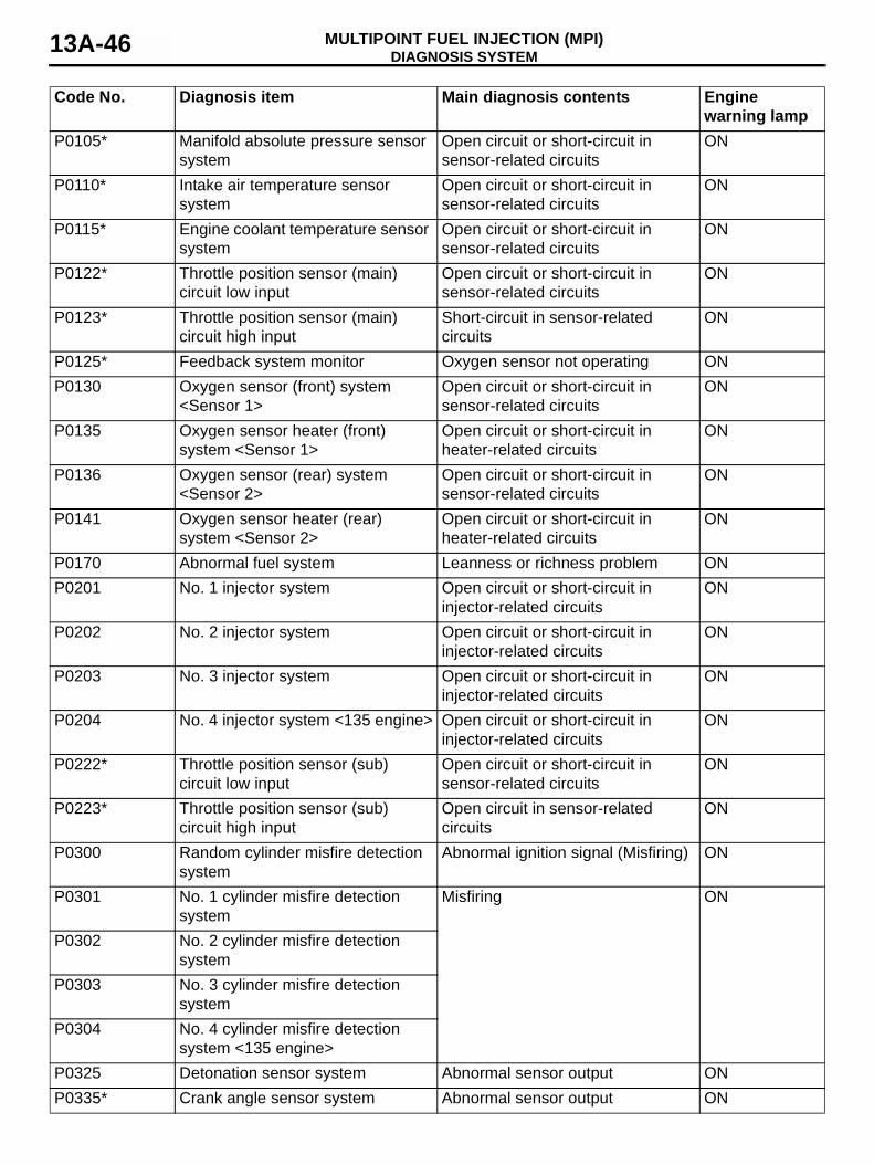
DIAGNOSIS SYSTEMMULTIPOINT FUEL INJECTION (MPI)13A-46
Code No. Diagnosis item Main diagnosis contents Engine warning lamp
P0105* Manifold absolute pressure sensor system
Open circuit or short-circuit in sensor-related circuits
ON
P0110* Intake air temperature sensor system
Open circuit or short-circuit in sensor-related circuits
ON
P0115* Engine coolant temperature sensor system
Open circuit or short-circuit in sensor-related circuits
ON
P0122* Throttle position sensor (main) circuit low input
Open circuit or short-circuit in sensor-related circuits
ON
P0123* Throttle position sensor (main) circuit high input
Short-circuit in sensor-related circuits
ON
P0125* Feedback system monitor Oxygen sensor not operating ONP0130 Oxygen sensor (front) system
<Sensor 1>Open circuit or short-circuit in sensor-related circuits
ON
P0135 Oxygen sensor heater (front) system <Sensor 1>
Open circuit or short-circuit in heater-related circuits
ON
P0136 Oxygen sensor (rear) system <Sensor 2>
Open circuit or short-circuit in sensor-related circuits
ON
P0141 Oxygen sensor heater (rear) system <Sensor 2>
Open circuit or short-circuit in heater-related circuits
ON
P0170 Abnormal fuel system Leanness or richness problem ONP0201 No. 1 injector system Open circuit or short-circuit in
injector-related circuitsON
P0202 No. 2 injector system Open circuit or short-circuit in injector-related circuits
ON
P0203 No. 3 injector system Open circuit or short-circuit in injector-related circuits
ON
P0204 No. 4 injector system <135 engine> Open circuit or short-circuit in injector-related circuits
ON
P0222* Throttle position sensor (sub) circuit low input
Open circuit or short-circuit in sensor-related circuits
ON
P0223* Throttle position sensor (sub) circuit high input
Open circuit in sensor-related circuits
ON
P0300 Random cylinder misfire detection system
Abnormal ignition signal (Misfiring) ON
P0301 No. 1 cylinder misfire detection system
Misfiring ON
P0302 No. 2 cylinder misfire detection system
P0303 No. 3 cylinder misfire detection system
P0304 No. 4 cylinder misfire detection system <135 engine>
P0325 Detonation sensor system Abnormal sensor output ONP0335* Crank angle sensor system Abnormal sensor output ON
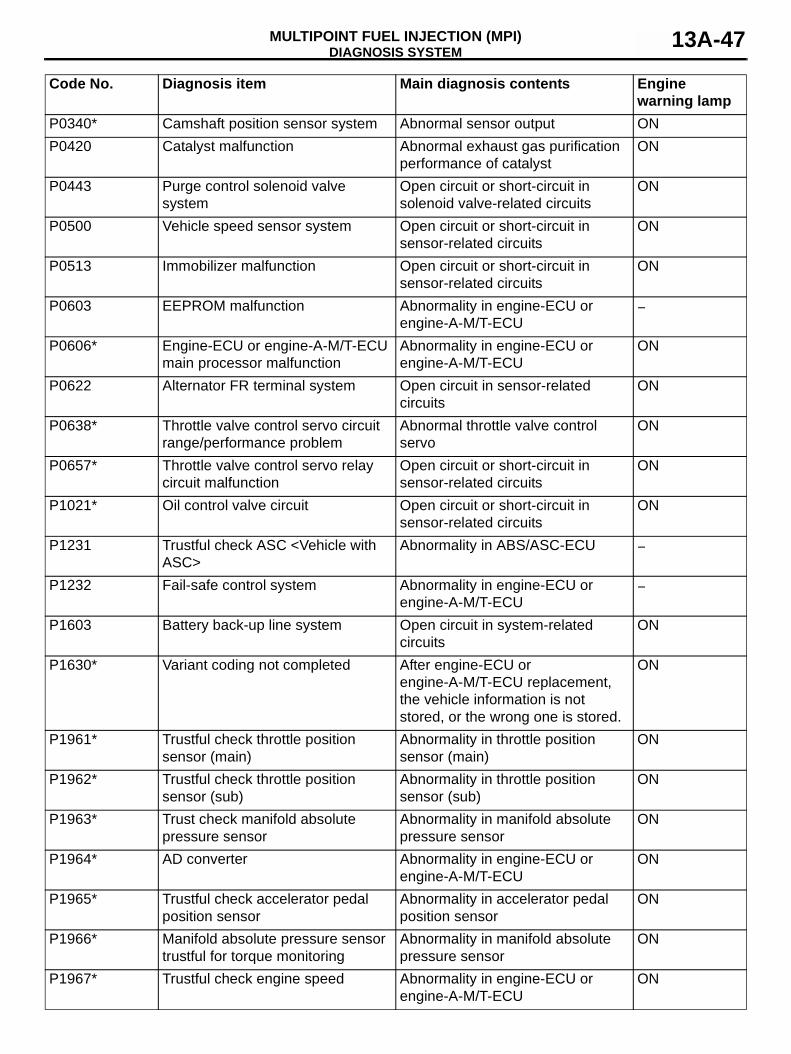
DIAGNOSIS SYSTEMMULTIPOINT FUEL INJECTION (MPI) 13A-47
P0340* Camshaft position sensor system Abnormal sensor output ONP0420 Catalyst malfunction Abnormal exhaust gas purification
performance of catalystON
P0443 Purge control solenoid valve system
Open circuit or short-circuit in solenoid valve-related circuits
ON
P0500 Vehicle speed sensor system Open circuit or short-circuit in sensor-related circuits
ON
P0513 Immobilizer malfunction Open circuit or short-circuit in sensor-related circuits
ON
P0603 EEPROM malfunction Abnormality in engine-ECU or engine-A-M/T-ECU
−
P0606* Engine-ECU or engine-A-M/T-ECU main processor malfunction
Abnormality in engine-ECU or engine-A-M/T-ECU
ON
P0622 Alternator FR terminal system Open circuit in sensor-related circuits
ON
P0638* Throttle valve control servo circuit range/performance problem
Abnormal throttle valve control servo
ON
P0657* Throttle valve control servo relay circuit malfunction
Open circuit or short-circuit in sensor-related circuits
ON
P1021* Oil control valve circuit Open circuit or short-circuit in sensor-related circuits
ON
P1231 Trustful check ASC <Vehicle with ASC>
Abnormality in ABS/ASC-ECU −
P1232 Fail-safe control system Abnormality in engine-ECU or engine-A-M/T-ECU
−
P1603 Battery back-up line system Open circuit in system-related circuits
ON
P1630* Variant coding not completed After engine-ECU or engine-A-M/T-ECU replacement, the vehicle information is not stored, or the wrong one is stored.
ON
P1961* Trustful check throttle position sensor (main)
Abnormality in throttle position sensor (main)
ON
P1962* Trustful check throttle position sensor (sub)
Abnormality in throttle position sensor (sub)
ON
P1963* Trust check manifold absolute pressure sensor
Abnormality in manifold absolute pressure sensor
ON
P1964* AD converter Abnormality in engine-ECU or engine-A-M/T-ECU
ON
P1965* Trustful check accelerator pedal position sensor
Abnormality in accelerator pedal position sensor
ON
P1966* Manifold absolute pressure sensor trustful for torque monitoring
Abnormality in manifold absolute pressure sensor
ON
P1967* Trustful check engine speed Abnormality in engine-ECU or engine-A-M/T-ECU
ON
Code No. Diagnosis item Main diagnosis contents Engine warning lamp
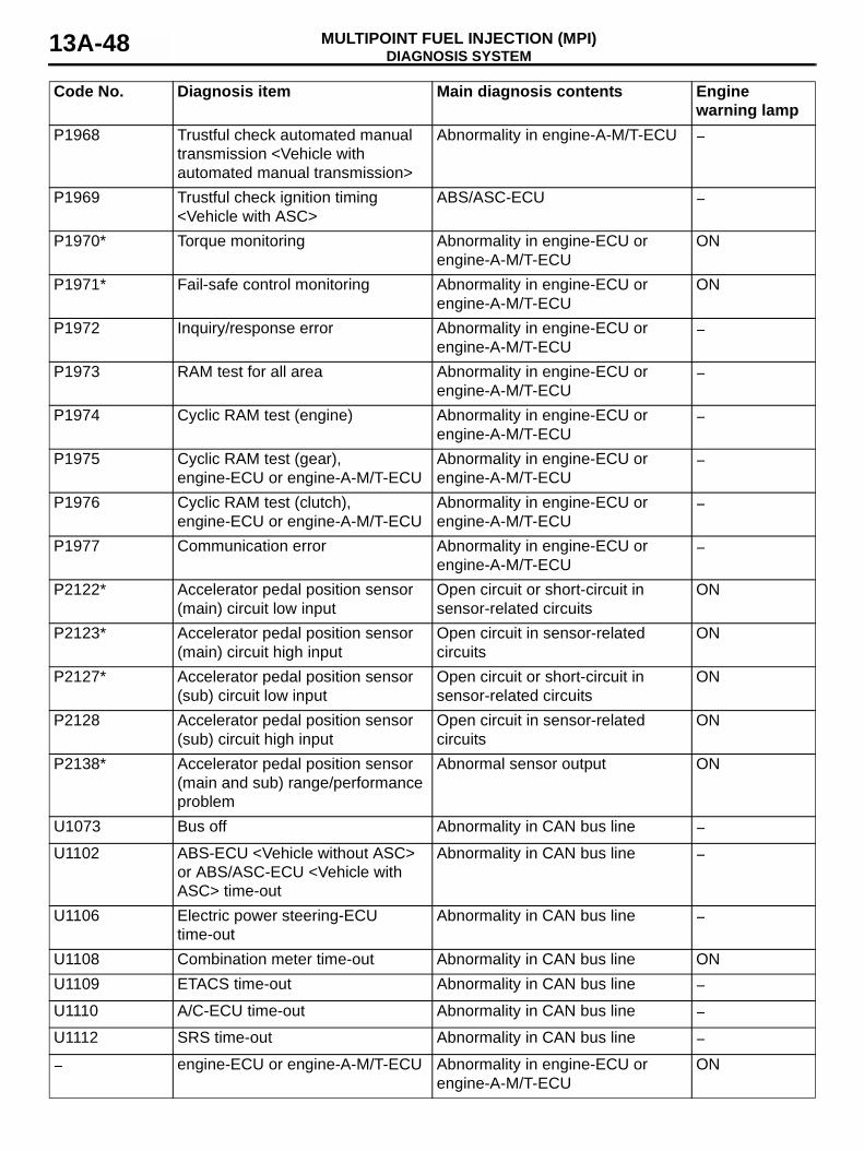
DIAGNOSIS SYSTEMMULTIPOINT FUEL INJECTION (MPI)13A-48
P1968 Trustful check automated manual transmission <Vehicle with automated manual transmission>
Abnormality in engine-A-M/T-ECU −
P1969 Trustful check ignition timing <Vehicle with ASC>
ABS/ASC-ECU −
P1970* Torque monitoring Abnormality in engine-ECU or engine-A-M/T-ECU
ON
P1971* Fail-safe control monitoring Abnormality in engine-ECU or engine-A-M/T-ECU
ON
P1972 Inquiry/response error Abnormality in engine-ECU or engine-A-M/T-ECU
−
P1973 RAM test for all area Abnormality in engine-ECU or engine-A-M/T-ECU
−
P1974 Cyclic RAM test (engine) Abnormality in engine-ECU or engine-A-M/T-ECU
−
P1975 Cyclic RAM test (gear), engine-ECU or engine-A-M/T-ECU
Abnormality in engine-ECU or engine-A-M/T-ECU
−
P1976 Cyclic RAM test (clutch), engine-ECU or engine-A-M/T-ECU
Abnormality in engine-ECU or engine-A-M/T-ECU
−
P1977 Communication error Abnormality in engine-ECU or engine-A-M/T-ECU
−
P2122* Accelerator pedal position sensor (main) circuit low input
Open circuit or short-circuit in sensor-related circuits
ON
P2123* Accelerator pedal position sensor (main) circuit high input
Open circuit in sensor-related circuits
ON
P2127* Accelerator pedal position sensor (sub) circuit low input
Open circuit or short-circuit in sensor-related circuits
ON
P2128 Accelerator pedal position sensor (sub) circuit high input
Open circuit in sensor-related circuits
ON
P2138* Accelerator pedal position sensor (main and sub) range/performance problem
Abnormal sensor output ON
U1073 Bus off Abnormality in CAN bus line −U1102 ABS-ECU <Vehicle without ASC>
or ABS/ASC-ECU <Vehicle with ASC> time-out
Abnormality in CAN bus line −
U1106 Electric power steering-ECU time-out
Abnormality in CAN bus line −
U1108 Combination meter time-out Abnormality in CAN bus line ONU1109 ETACS time-out Abnormality in CAN bus line −U1110 A/C-ECU time-out Abnormality in CAN bus line −U1112 SRS time-out Abnormality in CAN bus line −
− engine-ECU or engine-A-M/T-ECU Abnormality in engine-ECU or engine-A-M/T-ECU
ON
Code No. Diagnosis item Main diagnosis contents Engine warning lamp

DIAGNOSIS SYSTEMMULTIPOINT FUEL INJECTION (MPI) 13A-49
NOTE: When the first time a malfunction is detected, the engine-ECU or engine-A-M/T-ECU does not store a fault code. However, if the same malfunction is again detected the next time the engine is operated, a fault code is stored. For systems or components marked with "*" to be diagnosed, when the first time a malfunction is detected, a fault code is stored and the engine warning lamp is illuminated.
DATA LIST FUNCTIONThe data list items are given in the table belowItem No. Inspection item Unit001 Alternator G terminal duty %002 Power supply voltage V003 Crank angle sensor r/min004 Target idle speed r/min005 Vehicle speed sensor km/h006 Intake air temperature sensor °C007 Manifold absolute pressure sensor kPa008 Engine coolant temperature sensor °C009 Oxygen sensor (front) mV010 Oxygen sensor (rear) mV011 Accelerator pedal position sensor (main) mV012 Accelerator pedal position sensor (sub) mV013 Throttle position sensor (main) mV014 Throttle position sensor (sub) mV015 Ignition advance deg016 Injectors ms017 Idle speed control position learned value Step018 Idle speed control position learned value (A/C load) Step019 Air-fuel ratio feedback integration %020 Air-fuel ratio learning value of A zone (Low load) %021 Air-fuel ratio learning value of B zone (Low speed load) %022 Knock retard CA023 Learned knock retard %024 Accelerator pedal position sensor (main) learned value
(Closed position)mV
025 Oil control valve target current value mA026 Electric power steering current value (CAN) A027 Cranking signal (Ignition switch-ST) ON/OFF028 Purge control solenoid valve duty %029 MIVEC phase angle CA030 MIVEC phase angle target value CA067 Idle position switch ON/OFF073 Starter relay ON/OFF078 Brake lamp switch (CAN) ON/OFF
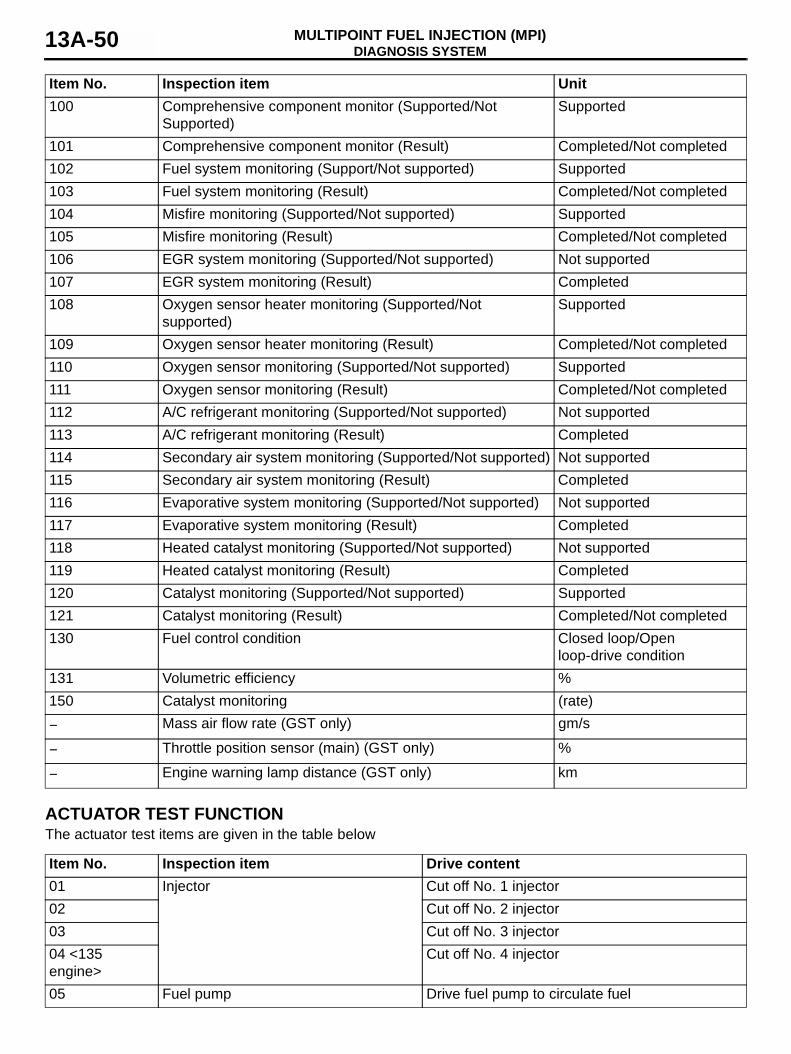
DIAGNOSIS SYSTEMMULTIPOINT FUEL INJECTION (MPI)13A-50
ACTUATOR TEST FUNCTIONThe actuator test items are given in the table below
100 Comprehensive component monitor (Supported/Not Supported)
Supported
101 Comprehensive component monitor (Result) Completed/Not completed102 Fuel system monitoring (Support/Not supported) Supported103 Fuel system monitoring (Result) Completed/Not completed104 Misfire monitoring (Supported/Not supported) Supported105 Misfire monitoring (Result) Completed/Not completed106 EGR system monitoring (Supported/Not supported) Not supported107 EGR system monitoring (Result) Completed108 Oxygen sensor heater monitoring (Supported/Not
supported)Supported
109 Oxygen sensor heater monitoring (Result) Completed/Not completed110 Oxygen sensor monitoring (Supported/Not supported) Supported111 Oxygen sensor monitoring (Result) Completed/Not completed112 A/C refrigerant monitoring (Supported/Not supported) Not supported113 A/C refrigerant monitoring (Result) Completed114 Secondary air system monitoring (Supported/Not supported) Not supported115 Secondary air system monitoring (Result) Completed116 Evaporative system monitoring (Supported/Not supported) Not supported117 Evaporative system monitoring (Result) Completed118 Heated catalyst monitoring (Supported/Not supported) Not supported119 Heated catalyst monitoring (Result) Completed120 Catalyst monitoring (Supported/Not supported) Supported121 Catalyst monitoring (Result) Completed/Not completed130 Fuel control condition Closed loop/Open
loop-drive condition131 Volumetric efficiency %150 Catalyst monitoring (rate)− Mass air flow rate (GST only) gm/s
− Throttle position sensor (main) (GST only) %
− Engine warning lamp distance (GST only) km
Item No. Inspection item Unit
Item No. Inspection item Drive content01 Injector Cut off No. 1 injector02 Cut off No. 2 injector03 Cut off No. 3 injector04 <135 engine>
Cut off No. 4 injector
05 Fuel pump Drive fuel pump to circulate fuel
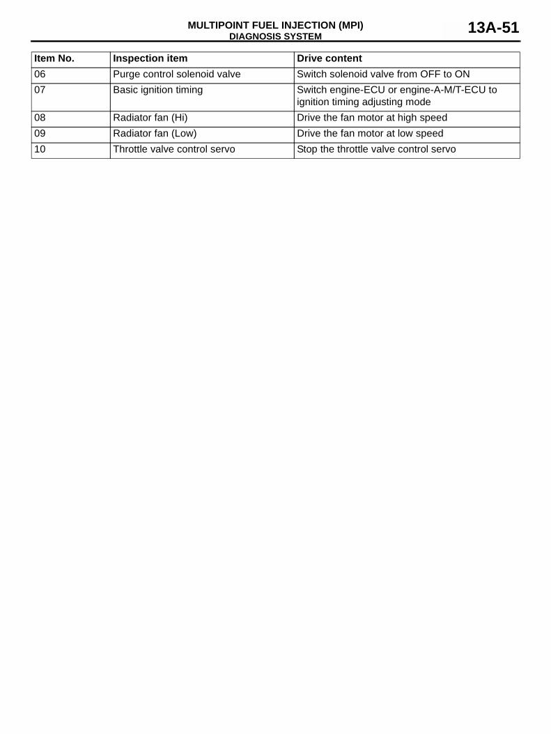
DIAGNOSIS SYSTEMMULTIPOINT FUEL INJECTION (MPI) 13A-51
06 Purge control solenoid valve Switch solenoid valve from OFF to ON07 Basic ignition timing Switch engine-ECU or engine-A-M/T-ECU to
ignition timing adjusting mode08 Radiator fan (Hi) Drive the fan motor at high speed09 Radiator fan (Low) Drive the fan motor at low speed10 Throttle valve control servo Stop the throttle valve control servo
Item No. Inspection item Drive content