a monocular pose estimation strategy for uav … · autonomous navigation in gnss-denied...
TRANSCRIPT
A Monocular Pose Estimation Strategy for UAVAutonomous Navigation in GNSS-denied
EnvironmentsAlejandro Rodrıguez-Ramos1, Carlos Sampedro1, Adrian Carrio1, Hriday Bavle1,
Ramon A. Suarez Fernandez1, Zorana Milosevic1, and Pascual Campoy1
Abstract—In this paper, an accurate, efficient, and simplevision-based pose estimation strategy for UAV navigation inGNSS-denied environments is presented. Using visual informa-tion and previous knowledge of 3D geometries present in theenvironment, the pose can be estimated accurately and used forautonomous navigation. The indoor mission in the IMAV 2016competition has been chosen for developing and evaluating thisapproach. Three Perspective-n-Point (PnP) algorithms have beentested and benchmarked with the purpose of selecting the mostsuitable for navigating in this scenario. All of them have beentested in a realistic Gazebo-based simulation using our novelUAV software, Aerostack, which allows for a fully autonomoussolution. A complete flight in a GNSS-denied environment hasbeen successfully simulated, indicating that real flights arefeasible with this approach.
I. INTRODUCTION
Nowadays, the field of micro aerial vehicles is evolvingvery rapidly due to its high versatility and the capability forperforming complex maneuvers in structured and unstructuredenvironments. Even though a lot of progress has been achievedduring the recent years, research efforts are still focused onobtaining fully autonomous systems that can perform highlevel missions such as the autonomous exploration of a GNSS-denied environment.
Performing such maneuvers in GNSS-denied environments,requires highly accurate position estimation and environmentmapping. For this purpose, some approaches are based onactive sensors like lasers [1]–[3], or sonars [4], [5]. Howeverthese approaches sometimes derivate in heavy weight or highpower consumption, affecting agility, endurance, and range ofthe UAV.
For addressing this problem, some approaches for localiza-tion using vision have been proposed, using only the informa-tion provided by a single camera [6], [7]–[9], or a stereo visionsystem [2], [10]–[12]. These kinds of localization strategiesprovide the advantage of a lightweight system which can beused in indoor as well as outdoor environments. However,using a vision based system for pose estimation and navigationis a very challenging task. For this purpose, some approacheshave used visual markers for retrieving the pose of the UAV[13]–[16]. In addition, optical flow based approaches have
1 All authors are with the Computer Vision Group, Center for Automationand Robotics (UPM-CSIC), Calle Jose Gutierrez Abascal 2, Madrid, Spain.
demonstrated their good capability for indoor navigation withobstacle avoidance [17]–[19].
In this paper, we present a simple and robust monocularpose estimation system for entering a building in a GNSS-denied environment by using the front camera mounted onboard the UAV as the main sensor for localization. In theproposed approach, a Computer Vision algorithm has beendeveloped for image detection of the entrances of a building,i.e. door and window, marked with colours. Once the entranceshave been detected, a PnP algorithm is used for computing thepose of the UAV based on the information provided by thedetection module, and the 3D geometry of door and windowin a global map, which is known. We compare the localizationaccuracy of three different pose estimation algorithms in orderto select the most suitable for an specific GNSS-denied flightscenario.
The rest of the paper is structured as follows: Section IIpresents the problem statement and Section III introduces theproposed methodology. In Section IV the obtained results aredescribed. Finally, Section V concludes the paper and pointstowards future research directions.
II. PROBLEM STATEMENT
The strategy presented in this paper has been proposedas part of CVG-UPM team solution for participating in TheInternational Micro Air Vehicle Conference and Competition(IMAV1), an international reference challenge for UAV au-tonomous navigation. This yearly event combines a scientificconference with a robotics competition using Micro Air Ve-hicles (MAVs) and focuses on research that can be appliedto real life scenarios. The indoor competition for the editionof 2016 requires one or multiple UAVs to enter a buildingin a drilling platform to move some important objects to safelocations in a GNSS-denied environment.
In our solution for this part of the competition, we proposea monocular vision approach for pose estimation outside thebuilding. Monocular vision can be used for pose estimationby visually recognising landmarks in the surrounding environ-ment which can serve as navigational aids for pose estimation,providing a cheap, lightweight and low consumption solution.In this case, we propose to use the front camera mounted on
1http://www.imavs.org

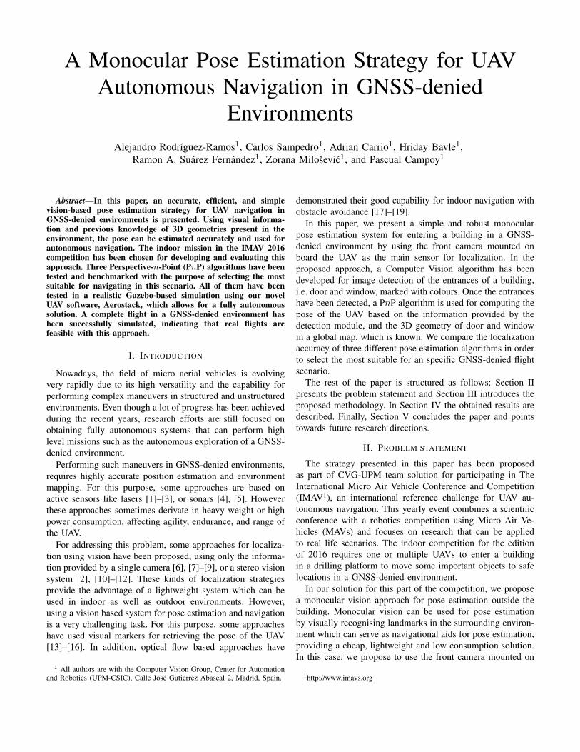
Fig. 1: Detections of door and window on the building facade.
board our UAV to capture RGB images of the building facade,detect door and window corners, whose frame of entrance willbe marked with predefined colours for visual aid. The proposeddetection strategy is based on two filters:• Color filter: This filter is based on the rules proposed
in the IMAV 16 competition for the entrances to thebuilding. The door of the building has a red coloredframe, while the frame of the window is blue. Taking thisassumption into account the color filter of the proposedstrategy is based on using the Opponent color space forenhancing the red and blue color. The proposed colorchannels are computed using equations 1 and 2.
O1 =[
1√2
−1√2
0]×
RGB
(1)
O2 =[0 −1√
21√2
]×
RGB
(2)
The next step is to apply a threshold in the correspondingcolor channels O1 and O2. Finally, an operation forfinding contours is applied to the thresholded images inorder to remove those contours with a small area.
• Shape filter: This filter is based on the geometry of theobjects to be detected. First, an edge detector based onCanny operator is applied. After that, some morphologicoperations (e.g. dilation) are applied in order to increasethe detected edge contours. Finally, the geometry of thecontours is taken into account for removing those whichdo not fit into a rectangle.
Once door and window corners have been detected, previousknowledge about their 3D geometry (in this case, their relativepositions and sizes) can be used to estimate the camera poseand therefore the UAV pose, by using a Perspective-n-Point(PnP) algorithm.
The aim of the Perspective-n-Point problem is to determinethe position and orientation of a camera given its intrinsic
parameters and a set of n correspondences between 3D pointsand their 2D projections. In this case, the 3D points are the3D coordinates of the door and window corners in an arbitraryreference system and their 2D image projections are obtainedusing the aforementioned detection strategy.
In the following section we present the methodology usedto compare the localization accuracy given by three PnPalgorithms, in an effort to determine the most suitable onefor localization in this specific navigation scenario.
III. PROPOSED METHODOLOGY
In this section, the proposed PnP algorithms to be comparedand the test bench structure of this analysis are presented.
A. Analyzed PnP algorithms
A set of three state-of-art PnP algorithms has been tested.As stated, these algorithms are sensitive to the number ofpoints and the distribution of the points over the space. Inthe following subsection, each algorithm is presented, as wellas their benefits and drawbacks in this specific scenario ofstudy.
1) Iterative PnP: This method is based on an iterativesolution based on Levenberg-Marquardt optimization. In thiscase, the function finds the pose of the corresponding objectwith respect to the camera that minimizes the re-projectionerror, that is, the sum of squared distances between theobserved 2D projections and the projected 3D object points.
2) Robust PnP (RPnP): This algorithm is a robust non-iterative solution of PnP. This method works well for bothnon-redundant point sets (n ≤ 5) and redundant point sets.In addition, this algorithm retrieves correct results robustly inthe three configurations of points (Ordinary 3D case, Planarcase and Quasi-singular case [20]), and its computationalcomplexity grows linearly with n.
In our scenario of study, the points are co-planar and thenumber of points oscillates between 4 to 8. RPnP is capable ofproviding a robust and accurate solution in our case of study.Nevertheless, depending on the configuration, a non-iterativesolution can lead to a lower accuracy compared to an iterativeapproach.
3) Efficient PnP (EPnP): [21] This method is based ona non-iterative solution to the PnP problem, in which the n3D points of the object are expressed as a weighted sum offour virtual control points. The coordinates of these controlpoints in the camera’s reference system can be calculatedby expressing these coordinates as a weighted sum of theeigenvectors of a 12× 12 matrix and solving a small constantnumber of quadratic equations in order to obtain the rightweights. This algorithm is applicable for n ≥ 4 in planar andnon-planar configurations, which make it very suitable for theproblem proposed in this paper.
B. Test Bench
The test bench is based on the Aerostack architecture anda Gazebo simulated environment. All three algorithms areevaluated using a common time reference and the same set

Fig. 2: IMAV’16 house replica, implemented in a Gazebomodel.
of 2D and 3D features. In the following subsections, the testbench is elucidated.
1) Aerostack Architecture: Aerostack (http://aerostack.org)is a software implementing fully autonomous navigation so-lutions for one or more heterogeneous UAVs. It is a versatile,robust and swarm-ready set of ROS packages. The autonomousnavigation of the UAV in simulation has been carried out byAerostack. A full description of Aerostack and its componentsfalls out of the scope of this paper and can be reviewed in [22]and [23].
2) Gazebo Simulation Environment: Gazebo simulator(http://gazebosim.org) is a powerful tool to rapidly test algo-rithms, design robots, and perform regression testing usingrealistic scenarios. It provides a versatile set of models andplugins (ROS compatible), as well as an easy-to-use Applica-tion Programming Interface (API).
A replica of the IMAV’16 indoor competition set has beencarefully designed in Gazebo simulator. All of the sizes ofthe mission elements, their colours (door and window frames)and their distribution in the scenario have been realisticallymodelled, in order to accurately test solutions before trying inthe real world. This is best depicted in Figure 2.
Furthermore, the physical appearance and dynamics of aParrot ARDrone 2.0 has been included, as well as differentextra sensors (RGB camera, LIDAR, RGB-D camera, IMU andothers). The autopilot has been simulated using a Software-In-The-Loop (SITL) simulation, in order to keep tests closer tothe real world solution.
3) Simulation details: A flight from the take-off point to anarea inside the house has been simulated. With a front RGBsimulated camera and the simulated movements of the UAV,a realistic set of images is obtained and used to detect thecorners of door and window. At any point of the flight, eitherthe door and/or the window are seen by this camera.
In addition, Gazebo provides ground truth data of the poseof the UAV, which is used for evaluation. The trajectoryfollowed by the UAV is shown in Figure 4.
PnP algorithms provide the pose of an arbitrary frame ofreference in which the 3D points are specified with respect
Fig. 4: UAV trajectory in the scenario of study
to the camera frame of reference. A transformation betweenthis frame and the Gazebo global frame of reference has beentaken into account for the PnP pose estimation results to becomparable with the ground truth data.
The position estimated by the three PnP algorithms andthe ground truth data have been compared. Mean, standarddeviation and maximum and minimum pose estimation errorshave been analysed.
IV. RESULTS AND BENCHMARK
In this section, the benchmarking results are presented.Different error indicators have been considered in order toprovide a suitable comparison among the whole set of PnPalgorithms.
The difference between the ground truth data and theposition estimated by the three PnP algorithms of study isbest depicted in Figure 3. The whole set of algorithms showsa proper performance, regarding the ground truth data. Theresults are not filtered or modified by any offset, so that thePnP estimation remains unaltered. In the z-axis the resultsremain the closest to the ground truth. This is due to the planarconfiguration of the case of study, since the points share thesame plane and they are perpendicular to the camera plane.This leads to an increased estimation error in x and y axes.
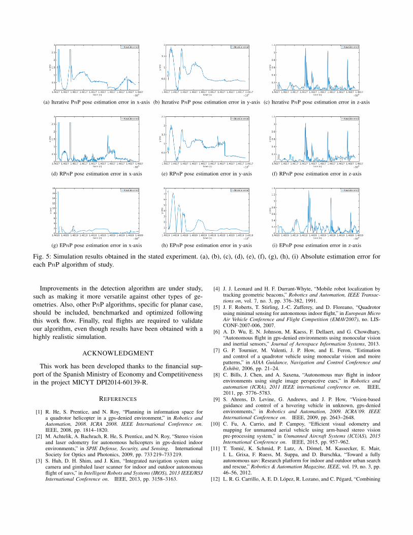
In addition, the absolute error for each PnP position esti-mation has been depicted in Figure 5. As shown, as the UAVgets closer to the house facade, the error decreases. This isdue to the fact that, for a fixed camera resolution, the objectsize in the image increases and subsequently PnP algorithmscan provide a better estimation in translation and rotation. Theerror in PnP algorithms is a function of the camera distancefrom the object space. In this planar configuration, where thepoints of the object space share the same plane, the error doesnot remain zero. PnP has some error in the estimation, due todifferent other sources of error, such as errors in the 2D featuredetection, estimation, camera calibration, etc. Nevertheless,the error estimation is enough to properly locate the UAV inthe whole environment and cross the window or the door forentering the building. This is possible by using an ExtendedKalman Filter (EKF) to fuse the data of various on board

(a) Iterative PnP pose estimation in x-axis (b) Iterative PnP pose estimation in y-axis (c) Iterative PnP pose estimation in z-axis
(d) RPnP pose estimation in x-axis (e) RPnP pose estimation in y-axis (f) RPnP pose estimation in z-axis
(g) EPnP pose estimation in x-axis (h) EPnP pose estimation in y-axis (i) EPnP pose estimation in z-axis
Fig. 3: Simulation results obtained in the stated experiment. (a), (b), (c), (d), (e), (f), (g), (h), (i) Pose estimation of everyalgorithm and Gazebo ground truth representation in every axis of the space.
sensors, such as an Inertial Measurement Unit (IMU), withthe pose estimation obtained using these techniques.
Other indicators, such as Squared Root Mean Quadratic(SRMQ), maximum and minimum position estimation errorcan be considered. This let the benchmark to be consistent inthe comparative analysis. In table I different error indicatorsare best enumerated.
TABLE I: Benchmark of the set of PnP algorithms.
Algorithm SRMQ (m) Max (m) Min (m) POOpenCV PnP 0.6571 2.696 (x-axis) 5E-4 (z-axis) No
RPnP 0.3711 2.6081 (x-axis) 4E-5 (z-axis) NoEPnP 2.4342 16.5752 (x-axis) 3E-05 (z-axis) No
The indicators for both Iterative PnP and RPnP resultedin being really similar, although RPnP shows slightly betterperformance. However, the error is acceptable, especially whenfiltering this data and fusing it with data from other sensors.Moreover, EPnP shows poorer performance, but still validfor this application. It can be observed that none of thesealgorithms implement internally a prediction and optimizationpost process (PO). This would lead to a finer performance withmore complex objects (more points spread in the object space)and does not require any other feeds of pose estimation. TheRPnP algorithm performed the best in the scenario of study.
Further optimizations can be made in order to decrease thestationary error.
These three state-of-art PnP algorithms have demonstratedto provide a proper performance for monocular pose estima-tion in GNSS-denied environments. Each of them combinedwith sensor fusion techniques, such as EKF, provide a com-plete solution for pose estimation, taking advantage of knowngeometries of the surrounding environment. The benchmarkhas revealed that the error is acceptable for real applications,with RPnP method remaining closely the best.
V. CONCLUSIONS AND FUTURE WORKIndoor and GNSS-denied environment navigation is an
extremely challenging task. To achieve this goal inexpensivelywithout extra sensors, monocular pose estimation algorithmscan be used. PnP pose estimation is based on previous knowl-edge of 3D geometries in the scenario for localization. ThreePnP algorithms has been tested and simulated. The simulationprovided proper results, showing that an autonomous entranceto an indoor environment is completely feasible with thisapproach. PnP has some error in the estimation, due to dif-ferent other sources of error but is accurate enough to providea precise localization at real-time frame rates. Furthermore,these results can be greatly improved when combined withother filtering and state estimation techniques.
(a) Iterative PnP pose estimation error in x-axis (b) Iterative PnP pose estimation error in y-axis (c) Iterative PnP pose estimation error in z-axis
(d) RPnP pose estimation error in x-axis (e) RPnP pose estimation error in y-axis (f) RPnP pose estimation error in z-axis
(g) EPnP pose estimation error in x-axis (h) EPnP pose estimation error in y-axis (i) EPnP pose estimation error in z-axis
Fig. 5: Simulation results obtained in the stated experiment. (a), (b), (c), (d), (e), (f), (g), (h), (i) Absolute estimation error foreach PnP algorithm of study.
Improvements in the detection algorithm are under study,such as making it more versatile against other types of ge-ometries. Also, other PnP algorithms, specific for planar case,should be included, benchmarked and optimized followingthis work flow. Finally, real flights are required to validateour algorithm, even though results have been obtained with ahighly realistic simulation.
ACKNOWLEDGMENT
This work has been developed thanks to the financial sup-port of the Spanish Ministry of Economy and Competitivenessin the project MICYT DPI2014-60139-R.
REFERENCES
[1] R. He, S. Prentice, and N. Roy, “Planning in information space fora quadrotor helicopter in a gps-denied environment,” in Robotics andAutomation, 2008. ICRA 2008. IEEE International Conference on.IEEE, 2008, pp. 1814–1820.
[2] M. Achtelik, A. Bachrach, R. He, S. Prentice, and N. Roy, “Stereo visionand laser odometry for autonomous helicopters in gps-denied indoorenvironments,” in SPIE Defense, Security, and Sensing. InternationalSociety for Optics and Photonics, 2009, pp. 733 219–733 219.
[3] S. Huh, D. H. Shim, and J. Kim, “Integrated navigation system usingcamera and gimbaled laser scanner for indoor and outdoor autonomousflight of uavs,” in Intelligent Robots and Systems (IROS), 2013 IEEE/RSJInternational Conference on. IEEE, 2013, pp. 3158–3163.
[4] J. J. Leonard and H. F. Durrant-Whyte, “Mobile robot localization bytracking geometric beacons,” Robotics and Automation, IEEE Transac-tions on, vol. 7, no. 3, pp. 376–382, 1991.
[5] J. F. Roberts, T. Stirling, J.-C. Zufferey, and D. Floreano, “Quadrotorusing minimal sensing for autonomous indoor flight,” in European MicroAir Vehicle Conference and Flight Competition (EMAV2007), no. LIS-CONF-2007-006, 2007.
[6] A. D. Wu, E. N. Johnson, M. Kaess, F. Dellaert, and G. Chowdhary,“Autonomous flight in gps-denied environments using monocular visionand inertial sensors,” Journal of Aerospace Information Systems, 2013.
[7] G. P. Tournier, M. Valenti, J. P. How, and E. Feron, “Estimationand control of a quadrotor vehicle using monocular vision and moirepatterns,” in AIAA Guidance, Navigation and Control Conference andExhibit, 2006, pp. 21–24.
[8] C. Bills, J. Chen, and A. Saxena, “Autonomous mav flight in indoorenvironments using single image perspective cues,” in Robotics andautomation (ICRA), 2011 IEEE international conference on. IEEE,2011, pp. 5776–5783.
[9] S. Ahrens, D. Levine, G. Andrews, and J. P. How, “Vision-basedguidance and control of a hovering vehicle in unknown, gps-deniedenvironments,” in Robotics and Automation, 2009. ICRA’09. IEEEInternational Conference on. IEEE, 2009, pp. 2643–2648.
[10] C. Fu, A. Carrio, and P. Campoy, “Efficient visual odometry andmapping for unmanned aerial vehicle using arm-based stereo visionpre-processing system,” in Unmanned Aircraft Systems (ICUAS), 2015International Conference on. IEEE, 2015, pp. 957–962.
[11] T. Tomic, K. Schmid, P. Lutz, A. Domel, M. Kassecker, E. Mair,I. L. Grixa, F. Ruess, M. Suppa, and D. Burschka, “Toward a fullyautonomous uav: Research platform for indoor and outdoor urban searchand rescue,” Robotics & Automation Magazine, IEEE, vol. 19, no. 3, pp.46–56, 2012.
[12] L. R. G. Carrillo, A. E. D. Lopez, R. Lozano, and C. Pegard, “Combining

stereo vision and inertial navigation system for a quad-rotor uav,”Journal of Intelligent & Robotic Systems, vol. 65, no. 1-4, pp. 373–387,2012.
[13] J. L. Sanchez-Lopez, J. Pestana, P. de la Puente, A. Carrio, and P. Cam-poy, “Visual quadrotor swarm for the imav 2013 indoor competition,” inROBOT2013: First Iberian Robotics Conference. Springer, 2014, pp.55–63.
[14] J. L. Sanchez-Lopez, J. Pestana, J.-F. Collumeau, R. Suarez-Fernandez,P. Campoy, and M. Molina, “A vision based aerial robot solution for themission 7 of the international aerial robotics competition,” in UnmannedAircraft Systems (ICUAS), 2015 International Conference on. IEEE,2015, pp. 1391–1400.
[15] P. Rudol, M. Wzorek, and P. Doherty, “Vision-based pose estimationfor autonomous indoor navigation of micro-scale unmanned aircraftsystems,” in Robotics and Automation (ICRA), 2010 IEEE InternationalConference on. IEEE, 2010, pp. 1913–1920.
[16] A. Amor-Martinez, A. Ruiz, F. Moreno-Noguer, and A. Sanfeliu, “On-board real-time pose estimation for uavs using deformable visual contourregistration,” in Robotics and Automation (ICRA), 2014 IEEE Interna-tional Conference on. IEEE, 2014, pp. 2595–2601.
[17] J.-C. Zufferey and D. Floreano, “Fly-inspired visual steering of anultralight indoor aircraft,” Robotics, IEEE Transactions on, vol. 22, no. 1,pp. 137–146, 2006.
[18] S. Zingg, D. Scaramuzza, S. Weiss, and R. Siegwart, “Mav navigationthrough indoor corridors using optical flow,” in Robotics and Automation(ICRA), 2010 IEEE International Conference on. IEEE, 2010, pp.3361–3368.
[19] F. Ruffier and N. Franceschini, “Visually guided micro-aerial vehicle:automatic take off, terrain following, landing and wind reaction,” inRobotics and Automation, 2004. Proceedings. ICRA’04. 2004 IEEEInternational Conference on, vol. 3. IEEE, 2004, pp. 2339–2346.
[20] S. Li, C. Xu, and M. Xie, “A robust o (n) solution to the perspective-n-point problem,” Pattern Analysis and Machine Intelligence, IEEETransactions on, vol. 34, no. 7, pp. 1444–1450, 2012.
[21] V. Lepetit, F. Moreno-Noguer, and P. Fua, “Epnp: An accurate o (n)solution to the pnp problem,” International journal of computer vision,vol. 81, no. 2, pp. 155–166, 2009.
[22] J. L. Sanchez-Lopez, J. Pestana, P. de la Puente, and P. Campoy,“A reliable open-source system architecture for the fast designing andprototyping of autonomous multi-uav systems: Simulation and experi-mentation,” Journal of Intelligent & Robotic Systems, pp. 1–19, 2015.
[23] J. Sanchez-Lopez, R. Suarez-Fernandez, H. Bavle, C. Sampedro, J. Pes-tana, M. Molina, and P. Campoy, “Aerostack: An architecture and open-source software framework for aerial robotics,” in Unmanned AircraftSystems (ICUAS), 2016 International Conference on, June 2016, p. 0.