a model of stabilizer roll bearing for a continuous hot
TRANSCRIPT

Graduate Theses, Dissertations, and Problem Reports
2006
A model of stabilizer roll bearing for a continuous hot-dip A model of stabilizer roll bearing for a continuous hot-dip
galvanizing line galvanizing line
Vishnu V. Rachamalla West Virginia University
Follow this and additional works at: https://researchrepository.wvu.edu/etd
Recommended Citation Recommended Citation Rachamalla, Vishnu V., "A model of stabilizer roll bearing for a continuous hot-dip galvanizing line" (2006). Graduate Theses, Dissertations, and Problem Reports. 3265. https://researchrepository.wvu.edu/etd/3265
This Thesis is protected by copyright and/or related rights. It has been brought to you by the The Research Repository @ WVU with permission from the rights-holder(s). You are free to use this Thesis in any way that is permitted by the copyright and related rights legislation that applies to your use. For other uses you must obtain permission from the rights-holder(s) directly, unless additional rights are indicated by a Creative Commons license in the record and/ or on the work itself. This Thesis has been accepted for inclusion in WVU Graduate Theses, Dissertations, and Problem Reports collection by an authorized administrator of The Research Repository @ WVU. For more information, please contact [email protected].
i
A Model of Stabilizer Roll Bearing for a
Continuous Hot-dip Galvanizing Line
VISHNU V. RACHAMALLA
Thesis submitted to the
College of Engineering & Mineral Resources at West Virginia University
in partial fulfillment of the requirements for the degree of
Master of Science
In
Mechanical Engineering
John Loth, PhD, Chair
Kenneth Means, PhD,
Victor Mucino, PhD
Department of Mechanical and Aerospace Engineering
Morgantown, West Virginia2006
Keywords: Galvanizing Line, Pot Hardware, Zinc Pot Roller, Conveyor Rollers
ii
ABSTRACT
A Model of Stabilizer Roll Bearing for a Continuous Hot-dipGalvanizing Line
VISHNU V. RACHAMALLA
The short service life of the hardware inside the molten zinc pot is often the cause
for the unscheduled shutdown of a galvanizing line. The lifetime of the hardware
used in these lines is not only a function of materials used but also on factors
such as line speed, sheet tension, bearing contact pressure, bearing alignment,
zinc pot temperature, corrosion as a function of pot chemistry, and surface finish
of the materials used. Dr. James Snider has developed a comprehensive data file
on the wear rate and corrosion properties of currently available bearing materials.
Dr. Snider’s dissertation research as well as this thesis work was funded under
DOE Project Award Number DE-FC36-01D14042. Snider’s research advisor Dr.
John Loth designed a new roller bearing configuration which reduces bearing
contact pressure by a factor of three without increase in bending moment. It
assures bearing alignment and loading uniformity on line. As wear rate is
proportional to contact pressure squared, this new configuration has the potential
for increased roller bearing life by up to 3^2 = 9 fold. West Virginia University
owns the patent rights to Loth's US Patent No: 7,040,482, issued May 9, 2006
and titled: "Bearing Life Extender for Conveyor Type Rollers". This thesis contains
detailed and dimensioned components for a redesigned roller for Weirton Steel
galvanizing Line No: 5. It uses an 8" diameter by 59.25" long roller, complete with
mounting hardware. This thesis describes the features of the new design and their
required component tolerances. All components and assemblies were drawn and
dimensioned using CAD software Pro-Engineer. The structural finite element
analysis performed in ANSYS 10.0.

iii
ACKNOWLEDGEMENTS
Firstly I would like to thank my parents and my brother for their great support and
encouragement without which none of this would have been possible.
I am very much grateful to my research advisor, Dr. John Loth for his guidance all
throughout the course of this project. His significant contributions would never be
forgotten. His invaluable knowledge in the field of design inspired me a lot. I would
like to thank Dr. Kenneth Means, Dr. Victor Mucino for serving as my committee
members.
I would also like to thank all my friends who have played their part in helping me
directly or indirectly in all my efforts and lending their support for the successful
completion of this project.
Finally, I express my gratitude to god for providing me an opportunity to pursue a
higher education.
iv
TABLE OF CONTENTS
ABSTRACT ............................................................................................................ii
ACKNOWLEDGEMENTS...................................................................................... iii
LIST OF FIGURES................................................................................................vi
LIST OF TABLES ..................................................................................................ix
NOMENCLATURE .................................................................................................x
CHAPTER 1- INTRODUCTION............................................................................. 1
1.1. The Continuous Hot Dip Galvanizing Process............................................. 1
1.2. Problems faced by galvanizers.................................................................... 4
CHAPTER 2 – LITERATURE REVIEW ................................................................. 6
2.1. Metallurgy of the galvanize coating ............................................................. 6
2.2. Metallurgy of Aluminum with the Steel....................................................... 10
2.2.1. Percentage of Aluminum in the coating .......................................... 11
2.3. Selection of Bearing Type ......................................................................... 13
2.3.1. Stresses acting on the Bearing....................................................... 14
2.4. Coating Types ........................................................................................... 17
2.4.1. Galvannealed Coatings .................................................................. 17
2.4.2. Galvalume Coatings ....................................................................... 18
2.5. Control of Coating thickness & its significance .......................................... 22
2.5.1. Coating Weight Range (Minimum/Maximum Thickness) ................ 23
2.5.2. ASTM Coating Designations........................................................... 26
2.6. Material Optimization - 316L Stainless Steel ............................................. 29
v
CHAPTER 3 – DESIGN ASPECTS OF POT ROLLERS..................................... 35
3.1. Objective ................................................................................................... 35
3.2. Wear Characteristics of Bearing Materials ................................................ 37
3.3. New Design for roll bearing to reduce wear-rate ....................................... 42
3.4. Stabilizer Roll Design ................................................................................ 49
3.5. Dimensioned Drawing Views..................................................................... 59
3.6. DISCUSSION OF THE DESIGN ............................................................... 71
CHAPTER 4 – SUMMARY AND RECOMMENDATIONS.................................... 72
REFERENCES .................................................................................................... 74
APPENDIX .......................................................................................................... 76
vi
LIST OF FIGURES
Fig 1.1: Zinc Pot Diagram...................................................................................... 2
Fig 1.2: Weirton Steel Operational Galvanizing Line Ranges6............................... 3
Fig: 2.1 Cross-Section of an Aluminum free galvanizing bath.1 ............................. 7
Fig: 2.2 Cross-section of a galvanize coating with aluminum containing bath.1... 11
Fig: 3.1 Stabilizer roll of about 8-inch diameter with cantilever shaft welded at
each end arms.5...................................................................................... 35
Fig: 3.2. Roll bearing sleeve and thrust plate shown welded to bridle support
arms.5 ..................................................................................................... 36
Fig: 3.3 Small scale material wear tester developed at WVU.6............................ 38
Fig. 3.4 Wear rate of 316 Stainless Steel seat by a 316 Stainless steel ball sample
submerged in water.5.............................................................................. 40
Fig.3.5 Wear rate of Stellite 6 seat by Stellite 6 Ball sample at 460°C.5 .............. 41
Fig.3.6 Conventional roll designs with short stubby shafts welded into roll and
flanges, thus supported as a cantilevered beam.5 .................................. 43
Fig: 3.7 Bearing Life Extender Assembly (Roll display is made transparent) ...... 46
Fig: 3.8 Stabilizer Roll (Exploded View)............................................................... 49
Fig: 3.9 Stabilizer Roll Assembly ......................................................................... 51
Fig: 3.10 Side View of the Roll Assembly without Clamping................................ 52
Fig: 3.12 Fixed Non-rotating Shaft....................................................................... 53
Fig: 3.13 Stabilizer Roll........................................................................................ 53
Fig: 3.14 Coated Bearing Sleeve......................................................................... 54

vii
Fig: 3.15 Ceramic Insert ...................................................................................... 54
Fig: 3.16 Insert Clamp ......................................................................................... 55
Fig: 3.17 Ceramic Clamp Spacer......................................................................... 55
Fig: 3.18 Hangar.................................................................................................. 56
Fig: 3.19 Collar to fit Hangar................................................................................ 56
Fig: 3.20 Welds Bearing to the Roll ..................................................................... 57
Fig: 3.21 Holds Ceramic in Clamp ....................................................................... 57
Fig: 3.22 Assembly Holding Key.......................................................................... 58
Fig: 3.23 Roll Assembly Lock .............................................................................. 58
Fig: 3.24 Coated Sleeve Bearing......................................................................... 59
Fig: 3.25 Fixed Non-rotating Shaft....................................................................... 60
Fig: 3.26 Stabilizer Roller..................................................................................... 61
Fig: 3.27 Ceramic Insert ...................................................................................... 62
Fig: 3.28 Insert Clamp ......................................................................................... 63
Fig: 3.29 Insert Clamp Spacer ............................................................................. 64
Fig: 3.30 Holds Ceramic in Clamp ....................................................................... 65
Fig: 3.31 Welds bearing to the roll ....................................................................... 66
Fig: 3.32 Collar to fit Hangar................................................................................ 67
Fig: 3.33 Tapered Key ......................................................................................... 68
Fig: 3.34 Hangar.................................................................................................. 69
Fig: 3.35 Roll Assembly Lock .............................................................................. 70
Fig: 3.36 Uniform Load acting on the Stabilizer Roll............................................ 76
Fig: 3.37 Free body Diagram (Shear Force & Bending Moment Diagram) .......... 77

viii
Fig: 3.39 Maximum deflection in ANSYS (beam elements) at X2=0 (in mm) ....... 80
Fig: 3.40 Maximum deflection in ANSYS (beam elements) at X2=5.625 (in mm) 81
Fig: 3.41 Comparison of Maximum Deflection values in ANSYS & Theoretical
Equation (in inches) ................................................................................ 81
ix
LIST OF TABLES
Table: 2.1 Percentage of Aluminum in different coatings.1 .................................... 9
Table 2.2 ASTM Standards for Coated Steel Sheet Products.1........................... 20
Table: 2.3 Coating Descriptions for Hot-dip Galvanized Sheet Products.1 .......... 27
Table: 2.4 Chemical composition of 316L.4 ......................................................... 30
Table: 2.5 Mechanical Properties of 316L at room temperature.4........................ 31
Table 2.6 Physical Properties of 316L Steel.4...................................................... 31
Table 3.1 Bill of Materials .................................................................................... 50

x
NOMENCLATURE
Winch/hour Wearing rate of the seat material
pc Laboratory ball on seat contact pressure
Vc Laboratory ball on seat contact velocity
Mmax Maximum Bending Moment acting on the shaft
F Uniformly distributed load on the shaft
L Span of the shaft
ymax Maximum deflection of the shaft
D Diameter of the roll
E Young’s Modulus of the shaft
I Moment of Inertia of the shaft
X1 Length of the roll between the two supports
X2 Free length of the roll beyond the supports
g Acceleration due to gravity
Density of 316L Stainless Steel
1
CHAPTER 1- INTRODUCTION
1.1. The Continuous Hot Dip Galvanizing Process
The working of a continuous hot-dip galvanizing line involves
immersing the steel in a bath of molten zinc where in the molten zinc is applied
onto a continuous ribbon of steel sheet passing over different rollers at high
speeds. The melting point of zinc is 419°C (786°F) and hence the bath must be
heated further to a temperature of approximately 455°C (842°C) or higher for the
galvanizing process to be more effective.
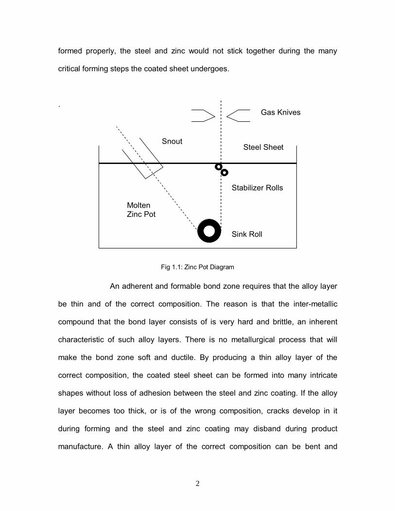
The pre-treated steel sheet dips into the molten zinc bath by
means of a snout over the sink roll which rotates with a sheet contact velocity up
to 200 m/min and then travels vertically upwards. To maintain the desired
uniform sheet thickness, two opposing gas knives (usually air) are employed.
One or two submerged stabilizer rolls are installed below the gas knives for sheet
stability and flatness. Usually, the steel sheet remains in the bath for 2 to 4
seconds and during this short duration the strong metallurgical bonding of the
zinc coating with the steel sheet takes place by diffusion. After wiping to the
desired coating thickness the zinc is cooled by air jets to solidify prior to reaching
the upper roll. The resulting bonding region formed is an inter-metallic compound
called the alloy layer whose thickness is 1 to 2 micrometers. This thin alloy
bonding zone is critical to allow recoiling and shipping for forming it into the
product. In order to get the forming operation done successfully, the steel and
zinc have to be well bonded to each other. If the bond zone is not formed or not
2
formed properly, the steel and zinc would not stick together during the many
critical forming steps the coated sheet undergoes.
.
Fig 1.1: Zinc Pot Diagram
An adherent and formable bond zone requires that the alloy layer
be thin and of the correct composition. The reason is that the inter-metallic
compound that the bond layer consists of is very hard and brittle, an inherent
characteristic of such alloy layers. There is no metallurgical process that will
make the bond zone soft and ductile. By producing a thin alloy layer of the
correct composition, the coated steel sheet can be formed into many intricate
shapes without loss of adhesion between the steel and zinc coating. If the alloy
layer becomes too thick, or is of the wrong composition, cracks develop in it
during forming and the steel and zinc coating may disband during product
manufacture. A thin alloy layer of the correct composition can be bent and
Gas Knives
Steel Sheet
Stabilizer Rolls
Snout
Sink Roll
MoltenZinc Pot

3
stretched without cracking and debonding. For the steel and zinc to form a proper
bonding zone, it is very important that the zone is thin. This can be accomplished
by focusing on the two major control points as follows:
1. The addition of controlled amount of aluminum (0.15 to 0.20%) to the
molten zinc bath and
2. Control of the steel sheet temperature at the point where it enters into
the molten zinc bath.
3. Control of the zinc bath temperature.
Fig 1.2: Weirton Steel Operational Galvanizing Line Ranges6.
4
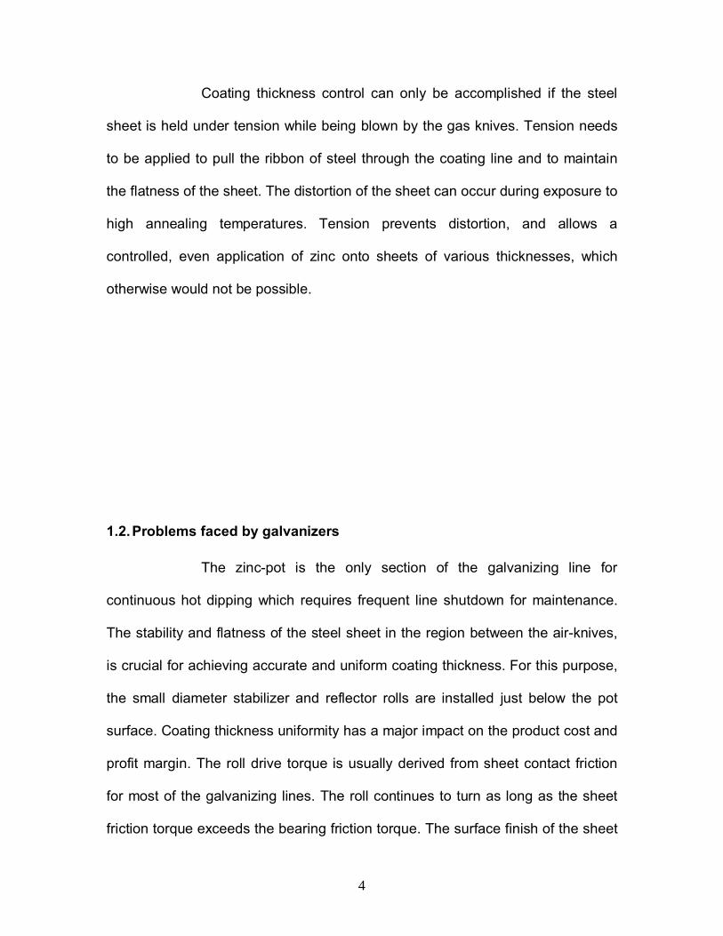
Coating thickness control can only be accomplished if the steel
sheet is held under tension while being blown by the gas knives. Tension needs
to be applied to pull the ribbon of steel through the coating line and to maintain
the flatness of the sheet. The distortion of the sheet can occur during exposure to
high annealing temperatures. Tension prevents distortion, and allows a
controlled, even application of zinc onto sheets of various thicknesses, which
otherwise would not be possible.
1.2. Problems faced by galvanizers
The zinc-pot is the only section of the galvanizing line for
continuous hot dipping which requires frequent line shutdown for maintenance.
The stability and flatness of the steel sheet in the region between the air-knives,
is crucial for achieving accurate and uniform coating thickness. For this purpose,
the small diameter stabilizer and reflector rolls are installed just below the pot
surface. Coating thickness uniformity has a major impact on the product cost and
profit margin. The roll drive torque is usually derived from sheet contact friction
for most of the galvanizing lines. The roll continues to turn as long as the sheet
friction torque exceeds the bearing friction torque. The surface finish of the sheet
5
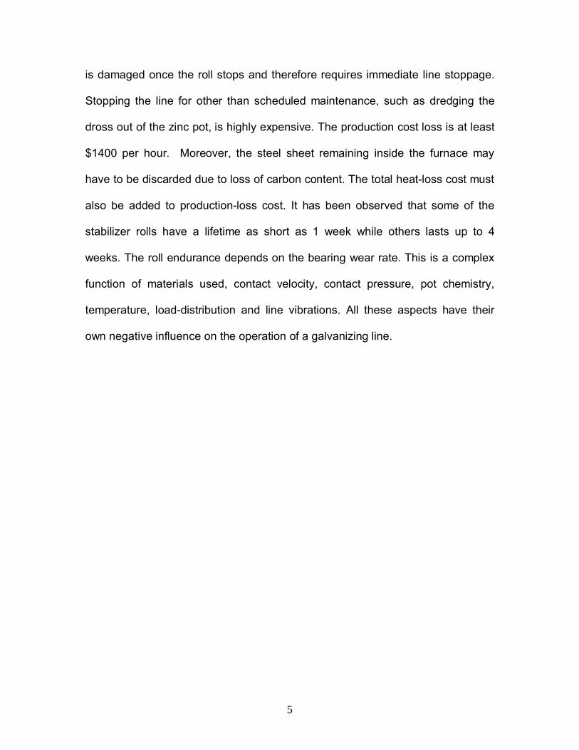
is damaged once the roll stops and therefore requires immediate line stoppage.
Stopping the line for other than scheduled maintenance, such as dredging the
dross out of the zinc pot, is highly expensive. The production cost loss is at least
$1400 per hour. Moreover, the steel sheet remaining inside the furnace may
have to be discarded due to loss of carbon content. The total heat-loss cost must
also be added to production-loss cost. It has been observed that some of the
stabilizer rolls have a lifetime as short as 1 week while others lasts up to 4
weeks. The roll endurance depends on the bearing wear rate. This is a complex
function of materials used, contact velocity, contact pressure, pot chemistry,
temperature, load-distribution and line vibrations. All these aspects have their
own negative influence on the operation of a galvanizing line.

6
CHAPTER 2 – LITERATURE REVIEW
2.1. Metallurgy of the galvanize coating
Continuous hot-dip galvanized sheet is made by immersing steel
sheet, as a continuous ribbon into the molten zinc pot. Both sides of the steel
sheet have to be very clean and free of surface oxides when introduced into the
coating bath. Typically, the sheet is cold rolled steel and is on-line annealed at
temperatures above 1200°F (650°C). Then it is cooled to approximately 875-
925°F (470-490°C) before entering the bath. The zinc which melts at 787°F
(419°C) is usually at a temperature of 870°F (465°C). Steel sheet has sufficient
high temperature strength so that it can be pulled through both the annealing
furnace and the zinc bath without distortion.1
The metallurgical reaction between the steel and the molten zinc
can be explained as follows. The surface atoms of the steel sheet, which are in
the solid state, interact with the zinc atoms in the bath, which are in the molten
state. This interaction is called diffusion. Zinc atoms move in the direction of the
steel and iron atoms in the steel migrate towards the molten zinc. The result is
the formation of a solid mixed layer between the steel and the molten zinc. This
layer contains zinc and iron atoms in specific proportions and is call an inter-
metallic compound. The mixing of atoms of different metals is known as alloying
and the diffusion zone that is formed during galvanizing is an inter-metallic alloy.
It is this alloy zone, when properly formed, provides the excellent bond between
the steel and the zinc coating.

7
Surface tension forces cause an outer layer of molten zinc to
adhere to the sheet when it leaves the molten bath. After excess zinc is wiped
off, the remaining liquid solidifies when it cools below 787°F (420°C). The final
product (galvanized sheet) consists of the steel core, with an inter-metallic alloy
layer and outer zinc layer on both surfaces.
Fig: 2.1 Cross-Section of an Aluminum free galvanizing bath.1
The cross-section of an aluminum-free galvanizing bath consists
of an outer zinc layer, the core steel metal and in between lays the inter-metallic
alloy. But in absence of aluminum these alloys have very poor ductility, i.e. they
are very hard and brittle. It is highly likely that shear cracks may develop when
the sheet is formed into a shape and the zinc coating flaking off as well thereby
drastically limiting the potential of the sheet to form into various shapes such as
drawn cups, roofing panels, tight lock seams, or highly stretched automotive
fenders.
8
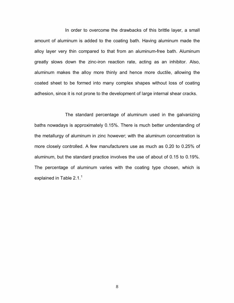
In order to overcome the drawbacks of this brittle layer, a small
amount of aluminum is added to the coating bath. Having aluminum made the
alloy layer very thin compared to that from an aluminum-free bath. Aluminum
greatly slows down the zinc-iron reaction rate, acting as an inhibitor. Also,
aluminum makes the alloy more thinly and hence more ductile, allowing the
coated sheet to be formed into many complex shapes without loss of coating
adhesion, since it is not prone to the development of large internal shear cracks.
The standard percentage of aluminum used in the galvanizing
baths nowadays is approximately 0.15%. There is much better understanding of
the metallurgy of aluminum in zinc however; with the aluminum concentration is
more closely controlled. A few manufacturers use as much as 0.20 to 0.25% of
aluminum, but the standard practice involves the use of about of 0.15 to 0.19%.
The percentage of aluminum varies with the coating type chosen, which is
explained in Table 2.1.1
9
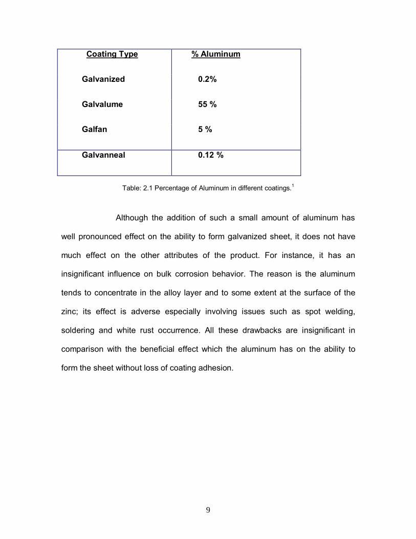
Coating Type % Aluminum
Galvanized 0.2%
Galvalume 55 %
Galfan 5 %
Galvanneal 0.12 %
Table: 2.1 Percentage of Aluminum in different coatings.1
Although the addition of such a small amount of aluminum has
well pronounced effect on the ability to form galvanized sheet, it does not have
much effect on the other attributes of the product. For instance, it has an
insignificant influence on bulk corrosion behavior. The reason is the aluminum
tends to concentrate in the alloy layer and to some extent at the surface of the
zinc; its effect is adverse especially involving issues such as spot welding,
soldering and white rust occurrence. All these drawbacks are insignificant in
comparison with the beneficial effect which the aluminum has on the ability to
form the sheet without loss of coating adhesion.
10
2.2. Metallurgy of Aluminum with the Steel
When a small percentage of aluminum is added to a coating bath,
the normal zinc-iron alloy compound FeZn7 that forms on the steel surface and
grows at a faster rate is no longer the most stable compound. Aluminum has
greater affinity for iron than zinc; so that within 0.15 seconds after the steel
enters the coating bath, the stable inter-metallic compound that forms is not a
zinc-iron compound but an aluminum-iron compound i.e. Fe2Al5. This alloy layer
so formed is very thin and retards the zinc-iron reaction. By the time the strip
leaves the bath some 2-4 seconds later, some amount of zinc is taken into the
layer but its nature is completely different from that which occurs in the absence
of aluminum. The layer now obtained is a ternary alloy layer composed of
approximately 45% Al, 35% Fe and 20-35% Zn (Fe2Al5-xZnx). Had it been liquid
zinc and solid iron only, the diffusion rate that occurs would have been very high
and a binary FeZn7 alloy in aluminum-free bath had been obtained. Instead, the
diffusion rate is now dependent on the transport characteristics of zinc through
the barrier created by the aluminum-iron compound. The reaction between the
zinc and iron is delayed, and the net result is that the final thickness of the alloy
layer is much less than when it is dependent on the diffusion rate across a
growing zinc-iron alloy zone.1

11
Fig: 2.2 Cross-section of a galvanize coating with aluminum containing bath.1
The figure above describes the nature of the alloy layer, when
aluminum is added to the galvanizing bath. The alloy layer is thin layer seen near
the bottom of the figure. With this thin and hence ductile alloy layer, it can be
formed into many useful shapes without any cracking and loss of coating
adhesion.
2.2.1. Percentage of Aluminum in the coating
For a typical galvanize coating bath, which contains 0.15-0.17%
Al, upon analyzing later, it was found to have a bulk aluminum content of 0.25-
0.40% Al. The answer lies in the strong affinity aluminum has for iron. The initial
alloy that forms is Fe2Al5 – by weight over 55% aluminum. Aluminum actually
concentrates at the steel-zinc interface and is taken out of the bath with the strip.
The thickness of the inhibition layer is independent of coating weight (mass). This

12
is why a lighter coating weight (mass) contains a higher overall percentage of
aluminum. The rate and method of aluminum addition to the bath must take into
account situations that cause its removal rate to vary, e.g. coating light gauge
sheet (high surface area) with a thin zinc coating removes aluminum at a much
higher rate than running heavy gauge sheet with a thicker coating. There are
other factors which have control over the amount of aluminum in the coating such
as immersion time, aluminum addition rate, zinc bath temperature and steel type.
One must take all these factors into account when planning how to replenish the
aluminum in the bath. Most galvanize producers, with the assistance of their zinc
suppliers; have developed aluminum addition algorithms for their zinc pots.
These prediction models forecast aluminum levels depending on product mix and
stipulate how to add aluminum bearing zinc to keep the aluminum in the bath at
the desired concentration.
In addition to the high percentage of aluminum in the inhibition
layer, the outermost atomic layers at the zinc surface contain a significant
amount of aluminum. This occurs due to solute rejection during freezing of the
zinc coating, which forces aluminum to the surface. In order that they can bond to
the zinc, chemical passivation and pre-painting treatments are designed to
remove the few high aluminum containing atomic layers at the surface.1

13
2.3. Selection of Bearing Type
For moderate speeds, plain sleeve bearings with boundary
lubrication serve reasonably well for longer periods without failure. They are the
best alternative to rolling element bearings. In case of the galvanizing lines, the
sleeve bearings do not need further lubrication since the whole bearing setup is
immersed in the galvanizing solution. The sleeve bearings do not pose the
danger of unexpected fatigue failures as in case of the roller bearings. The major
advantage of the sleeve bearings is that it is possible to continue the machine
running for a longer period of time even when they wear out. They can be
replaced online at a much convenient time. Hence, to a great extent all the
financial, energy, production and time losses involved in a line shutdown can be
prevented. It is much easier to mount and replace the sleeve bearings without
even removing the shaft. However, they cannot carry higher loads because the
sleeve bearings support the load at a single point unlike the roller bearings.
Moreover, the sleeve bearings are less sensitive to dust, slurry and corrosion.
However, the sleeve bearings require higher maintenance costs as compared to
roller bearings. They are comparatively expensive to manufacture as well.
Considering the advantages and disadvantages as well as the long-term effects
on the life of the galvanizing line, most of the manufacturers opt for the sleeve
bearings to minimize the overall production losses in the long run.2
14
2.3.1. Stresses acting on the Bearing
Bending is the most common shaft stress. It is the deflection of
the shaft as a result of the load applied to it. Torque loading or twisting of a shaft
is directly influenced by the drive3 and the driven machinery connected to it. Both
torque and bending loads must be considered for any shaft design. But as in this
case, the shaft is fixed, there is no torque load associated with it. The sleeve
bearings are affected by torque and offer more resistance if the shaft is rotating.
Axial loading also has its effect on the bearing. The sheet steering causes an
axial load which can cause horizontal or lengthwise movement of the shaft. The
amount of axial deflection varies with the size, length, and temperature
encountered. The maximum load would be at the centre which in case of two
fixed bearings which can cause fair amount of damage.
A bearing manufacturer for the galvanizing line has to consider the following
criteria while designing the bearing:
1. Load capacity – the weight and pressure exerted on the bearing.
2. Speed – the rotational speed at which the bearing would operate.
3. Life Expectancy – which the bearing must fulfill.
4. Fatigue factor – the extent to which it must be subjected for it can
withstand extreme loading conditions.
5. Mounting, replacement & maintenance – the ease with which the bearing
could be mounted, replaced & maintained without affecting the above
factors.
15
6. Bath Chemistry – as the whole setup is immersed in a galvanizing line, the
bearing life depends upon the bath chemistry as well.
The following is an assumption of factors affecting roll:
• Load Capacity – The contact load or contact pressure acting on the
bearing is a prime design parameter. The load capacity of a bearing is
its ability to withstand a given amount of weight or pressure. It varies
with the different shapes and sizes of the bearing. The speed of
operation of a galvanizing line and the bearing life expected play a
significant role. In comparison to anti-friction bearings, the sleeve
bearings can take up relatively smaller loads. But as the surface area
is much larger than the anti-friction bearings, they are not easily
subjected to fatigue stresses.
• Speed – The sleeve bearings have some sort of limitation over their
operating speed. The speeding rate is in inverse proportion to the
loading rate. Higher speeds imply smaller loading rate to ensure proper
functioning of the bearing.
• Life – The bearing in a galvanizing line is designed for a long life. As
stated before, the bearing life is directly affected by contact pressure
and velocity. The longer the life, the less contact pressure it can
support for any given velocity, or the less velocity at which it can
operate for any given contact pressure. Going for a bearing which has
a longer life is preferred to buying less expensive bearings and
16
replacing them more often. The cost of repairing the equipment is
based more on the cost of labor and the inconvenience of taking the
unit out of service. It is preferable to replace a very old setup that has
been running on for several years rather than paying for its repair
keeping in view the cost savings that can be expected from future
repair costs.
• Fatigue – The sleeve bearings used in a galvanizing line have a larger
surface contact area when compared to anti-friction bearings. Hence,
the problem of fatigue can be almost overlooked.3
• Bath Chemistry – The bath chemistry contributes to the wear of the
bearing. The galvanizing solution at a temperature of about 850°F
wears away the surfaces of the hardware used in the zinc pot.
17
2.4. Coating Types
2.4.1. Galvannealed Coatings
Applying a galvanneal coating involves combining of zinc atoms
with iron atoms in a steel surface at high temperatures. First, the steel sheet is
immersed in a liquid zinc bath at about 842ºF (450ºC). Then it is made to pass
through a cascade of furnaces, the temperature raised to as high as 1292ºF
(700ºC). During the heat treatment process, the iron atoms from the molten steel
sheet drift into the zinc coating to form the zinc-iron alloy. The protective inter-
atomic layer of zinc-iron alloy prevents the steel from corrosion through.
However, the most significant aspect involving in this process is to ensure that
the molten steel surface is at the right temperature, which eventually leads to the
formation of the best galvanneal coating. Making galvanneal involves growing
zinc-iron alloy compounds throughout the coating, so that it has approximately 9
to 10% bulk iron content. The presence of aluminum restricts the growth of alloy
layer, affecting the production of galvanneal. The reheating of the steel, which is
necessary to produce galvanneal, restarts the zinc-iron diffusion reaction. Within
seconds the heat breaks down the aluminum-iron inhibition layer. For this to
happen consistently require aluminum control that was not possible in the early
days of continuous galvanizing. Producing galvanneal depends on the zinc and
steel alloying at a rate high enough so that complete diffusion of iron throughout
the coating can be accomplished in a reasonable timeframe (allowing production
to be done at economical rates). Inhibition layers formed in galvanneal zinc baths
are generally thinner than those formed in galvanizing baths. In fact, the inhibition
18
layer formed in higher aluminum galvanizing baths may not allow the galvanneal
reaction to proceed properly in the time allowed. When the aluminum
concentration in the bath is reduced to less than 0.15% (in the range of 0.12% to
0.14%), the ternary alloy layer1 is sufficiently thin, and of the right composition,
that reheating allows the required amount of diffusion to occur in a matter of
seconds. After the coating has been converted to galvanneal the aluminum-iron
alloy interface layer no longer exists. This layer and the small amount of extra
aluminum at the surface become diffused into the zinc-iron coating. For a
producer making both galvanize and galvanneal products on the same coating
line initially uses 0.15% to 0.19% aluminum for galvanized production and then
allows the aluminum level to drop below 0.15% to make galvanneal. In practice, it
is as difficult as it appears, since there is very less time for the transition to take
place. For this, precise aluminum control is needed requiring accurate measuring
capabilities.1
2.4.2. Galvalume Coatings
A Galvalume coating comprises of 55% aluminum, 43.5% zinc
and 1.5% silicon. It finds its primary use in metal building roofing, long-life roofing
sheets especially low slope roofing on industrial buildings. It has been widely
applied as unpainted sheet with the coating being directly exposed to the
atmosphere. Galvalume steel sheet is also used a substrate for pre-painted
sheet when a more decorative finish is desired and the use has recently shown
significant rates of growth. When used for low slope roofing, Galvalume has

19
performed extremely well for over 25 years and in many cases over 30 years,
without failure. Often the roofs retain their bright metallic finish for over 25 years
in areas where the atmosphere does not contain too much particulate matter.
The term 55Al-Zn is the most well known trade name used. In the manufacture of
55Al-Zn, the inclusion of 1.5% silicon is significant. The major purpose of
inclusion of silicon is to suppress the growth of the brittle inter-metallic layer that
would otherwise form during manufacture of the product.1 Thus, addition of
silicon is essential and the 55Al-Zn product cannot be manufactured without it.
The interaction between the steel sheet and the molten coating during the
manufacture process is vital to achieve good adhesion of the coating during
eventual forming operations in case of the hot-dip galvanized sheet. Even so, the
inter-metallic alloy layer formed is hard and brittle and it is therefore important for
this layer to be kept as thin as possible. Inclusion of silicon takes care of this
aspect. It restricts growth of the alloy layer, allowing the product to be readily
formed after manufacture. Silicon does not play any role in preventing corrosion.
In some applications, especially those that involve deep drawing, the coating
adhesion of the as-produced product is not as good as that of a galvanized
coating. The inhibition of the alloy layer growth is not as effective with the
addition of silicon to a 55Al-Zn bath as it is when aluminum is used in a
galvanizing bath. A galvanized sheet is often the preferred product for this reason
and also for reduced galling (abrasion) behavior. The recent developments in
coating technologies though, in particular the use of acrylic coatings facilitate
55Al-Zn for some deep drawing and other forming operations. Despite better

20
corrosion performance than galvanized steel depending on the environment,
there are several notable exceptions. The most important one is that in closed
animal confinement buildings. Buildings that house the intensive farming
activities of certain animals, especially pigs, can present problems for 55Al-Zn
coated sheet. The animal waste and waste decomposition by-products have
been found deleterious towards 55Al-Zn coated sheet. Also, unpainted
galvalume sheet cannot come in direct contact with wet concrete. Concrete’s
high alkalinity attacks the aluminum, causing the coating to become porous and
prone to corrosion.1
Coating Method ASTM Standard Comments
Hot-dip galvanized A 653/A 653/M Zinc coated sheet
Hot-dip galvannealed A 653/A 653/M Zinc-iron alloy coated sheet
Electro galvanized A 879/A 879/M Electroplated zinc coated sheet
Galvalume A 792/A 792/M 55%Al 45%Zn alloy coated sheet
Galfan A 875/A 792/M 95%Zn 5%Al alloy coated sheet
Aluminized A 463/A 463/M 2 types of Aluminum coatings
• Pure Al coated sheet
• 5%Al 11%Si alloy coated sheet
Teme A 308/A 308/M Lead-Tin alloy coated sheet
Electroplated Zn/Ni A 918 9%Zn 16%Ni alloy electroplated
coated sheet
Table 2.2 ASTM Standards for Coated Steel Sheet Products.1

21
Interpretation of ASTM Standards
The ASTM Standard number A 653/A 653M means a dual
standard and allows the product to be ordered in either “inch-pound” (English)
units, or SI (Metric) units. The two sets of units are to be regarded separately as
standard units. In the text the SI units are shown in brackets. One has to keep in
mind that the values stated in each system are not exact equivalents and each
system must be used independently of the other. In this example, when ordering
galvanize to inc-pound units, specify A 653. When ordering to SI units, one
needs to specify A 653M. However, there are exceptions for some of the electro-
galvanize products in that the ASTM numbers do not imply dual specifications for
instance A 917 and A918. These standards which don’t have an M after the
number specify only SI units.1

22
2.5. Control of Coating thickness & its significance
It is the coating thickness that determines coating life in any given
application; the normal practice is to specify and manufacture to coating weight
(inch-pound system) though. Since the density of zinc is well known, it is easy to
calculate the thickness of a galvanized coating once the coating weight (mass) is
determined.
It becomes highly important that the coating thickness is properly
controlled. Most of the coating lines employed in various industries today have
highly potential coating thickness controlling equipment to meet end-user needs.
These coating lines, which operate at 600 feet/minute and higher use very
specialized equipment to ensure the correct coating thickness applied to the
sheet.
In a typical arrangement, the steel sheet exits the bath at high
speeds, and as it exits, it drags out more zinc than is needed for coating. The
higher the line speed, the more zinc is dragged out of the bath. The thickness of
zinc on the sheet is then controlled by using gas knives to wipe off excess zinc
while allowing the desired amount to pass through the knives. A typical gas
knives setup employs low-pressure/ high volume gas streams (usually air, rarely
nitrogen) that impinge against the sheet surfaces. The pressurized air is
generated by blowers. The air flows from the blower through piping up to a
position parallel and adjacent to the strip. It is then allowed to escape through a
precisely designed and machined slot opening or orifice that is placed about 0.5
23
inch or less from the traveling strip. The resulting air jet acts a knife, stripping the
excess molten zinc and forcing it back in the direction of the coating bath surface.
Pressure/volume is the principal control parameter, although height above the
bath, distance to the strip, angle of the knives, and knife orifice gap are also
controlled.
Of late, automatic coating weigh (mass) control systems using
artificial intelligence technology have been installed on many lines to produce
consistent coating thickness with low standard deviation. The degree of control
required depends on the thickness that is being applied. The thinner the coating,
the more is the control required. The producer can use a set of small rolls located
immediately beneath the zinc bath surface to keep the sheet uniformly distant
from each knife orifice. This kind of arrangement is quite significant to obtain the
desired uniform thickness of coating on both sides of the sheet.1
2.5.1. Coating Weight Range (Minimum/Maximum Thickness)
Minimum Coating Thickness
The minimum thickness is primarily limited by the amount of air
(pressure and volume) that is practical to use during the production. More is the
air intensity blowing onto the sheet, less is the coating thickness. The rate of
decrease in the coating thickness as the knife parameters are adjusted becomes
limiting when the coating thickness gets down to about 0.00025 inch (about 6
microns). This is not an absolute number as the design of the air knives and the
24
processing speed govern the lowest coating thickness that is achievable. If the
air pressure and volume are increased further, or the knives are moved too close
to the strip, the zinc exhibits a tendency to freeze at the air knife location. If this
occurs, there is obviously no further wiping action. The speed of the sheet when
it exits the coating bath has a large influence on the volume of zinc that needs to
be wiped off. The higher the sheet speed, the higher the air pressure and volume
needed to obtain the specific coating thickness, therefore the thinnest coating
achievable is influenced by line speed. As the processing speeds used on
coating lines are usually dictated by the annealing furnace design, it is common
for thin gauge sheet to be processed at high speeds and for thick gauge sheet to
be processed at lower speeds. It is reasonable to expect that the thinnest
coatings might only be possible on heavier gauge strip. This is true except for
one offsetting factor. The sheet and coating metal react to form an alloy layer
during the time that the sheet is immersed in the coating bath. This alloy layer is
solid and cannot be wiped off by the air knives. The longer the sheet is immersed
in the bath, the thicker is the alloy layer. Hence, heavy gauge sheet being
processed at lower speeds is immersed in the coating bath longer than light
gauge sheet and typically has a thicker alloy layer. Since the alloy layer is a part
of the final total coating thickness, it is not necessarily true that heavy gauge
sheet can be coated with the thinnest coatings.1
25
Maximum Coating Thickness
The maximum coating thickness is limited by a number of issues,
but the primary one is the amount of zinc that can be dragged from the bath.
Since it is governed by the property of the surface tension of the liquid zinc, the
amount of zinc being dragged at low speeds is less than at high speeds, so it is
difficult to achieve a thick coating on heavy gauge sheet. Heavy gauge sheets
are usually processed at lower line speeds because of the limitations of the
annealing furnace. A heavy gauge sheet is often a product that is intended to
have a thick coating since it is used for long times in service. In order to achieve
this, the galvanized sheet manufacturers apply special practices to heavy-gauge
sheet to achieve thicker coatings like for instance increasing the surface
roughness of the steel substrate. A rougher surface results in more zinc being
dragged out any given speed. In addition to being limited by the amount of zinc
that is dragged out of the coating bath, there is another practical limitation. There
arises a tendency for the molten coating metal to sag due to gravity if the coating
is too thick after it passes through the air knives towards the Stabilizer roll above
the coating pot. The coating immediately adjacent to the steel surface is held in
place by surface tension between the molten coating and the solid alloy layer.
Also, the outer surface of the molten coating has a solid but very thin layer of
oxide. This oxide layer attempts to hold the molten coating in position until it has
fully solidified. But, as the thickness of the molten layer increases, the coating
may break through the oxide layer and thereby causing local sagging. This
causes formation of a non-uniform thickness on the sheet surface, one that can
26
be unsightly as well as affecting the time before rusting of the steel begins. It is
highly necessary that the coating is uniformly thick to avoid localized early onset
of red rust. The practical maximum thickness depends on many specifics of the
particular coating line, but realistically, coatings thicker than about 0.002 inch
often have coating sags.1
2.5.2. ASTM Coating Designations
The ASTM standard specifications such as A 653/A 653M cover
continuous hot-dip galvanized sheet products taking into account the
minimum/maximum coating thickness limitations. The following table contains
the coating designations that are recognized in A 653/A 653M.

27
Units Coating Designation Minimum Coating
Weight (oz/ft2)
Inch-Pound G360
G300
G235
G210
G185
G165
G140
G115
G90
G60
G30
G01
3.60
3.00
2.35
2.10
1.85
1.65
1.40
1.15
0.90
0.60
0.30
No minimum
Table: 2.3 Coating Descriptions for Hot-dip Galvanized Sheet Products.1
The maximum coating thicknesses, G360 and G300, cannot be
applied to all thicknesses of sheet. Also, the tendency for sags to develop in
coatings this thick is high. On the other end of the range, the thinnest coating,
G01 has no specified minimum thickness. This designation clearly recognizes
that there is a physical limit to the thinnest achievable coating thickness. Even a
G30 coating at approximately 0.0003 inch thick is beyond the thinnest

28
designation that is achievable on some coating lines when processing the sheet
at high speeds.
The galvanizing industries today have been trying to enhance the
quality of the coating applied owing to the increased use of galvanized sheet as
exposed automobile panels. Deterioration of the submerged pot hardware
causes excessive strip vibration and poor surface quality.
29
2.6. Material Optimization - 316L Stainless Steel
The type 316 is an austenitic chromium stainless steel alloy
containing molybdenum. The addition of molybdenum causes increase in the
general corrosion resistance particularly higher resistance to pitting and crevice
corrosion in chloride environments. It also exhibits increased strength at elevated
temperatures. Hence grade 316 shows greater corrosion resistance in both
acidic and alkaline environments, especially against sulfuric acid, formic acid
besides alkaline chlorides. The austenitic structure gives it great toughness, even
down to cryogenic temperatures.4
It has outstanding forming and welding characteristics. It can be
readily brake or roll formed into a wide variety of parts for applications in the
industrial, architectural and transportation fields. It also has excellent welding
characteristics. Moreover, for welding thin sections, even post-weld annealing is
not necessary.
The extensive use of 316L includes furnace parts, exhaust
manifolds, heat exchangers, jet engine parts, pharmaceutical and photographic
equipment besides weldments. 316L is an extra-low carbon version of 316.The
low carbon content helps minimizing harmful carbide precipitation due to welding
assuring optimum corrosion resistance.
The table 2.4 gives the information regarding the composition of 316L.

30
Element Percentage (%) in 316L
Carbon 0.03
Manganese 2.00
Phosphorus 0.045
Sulfur 0.03
Silicon 0.75
Chromium 16-18
Nickel 10-14
Molybdenum 2-3
Nitrogen 0.10
Iron Rest
Table: 2.4 Chemical composition of 316L.4
Usually, 316L sheets are available up to a thickness of 0.01” to
0.25” with widths up to 50”. The mechanical properties of 316L at room
temperature are shown in table 2.5.
31
Property Units
UTS 580 MPa
0.2 % YS 300 MPa
Rockwell Hardness 95
Modulus of elasticity 200 GPa (in tension)
80 GPa (in torsion)
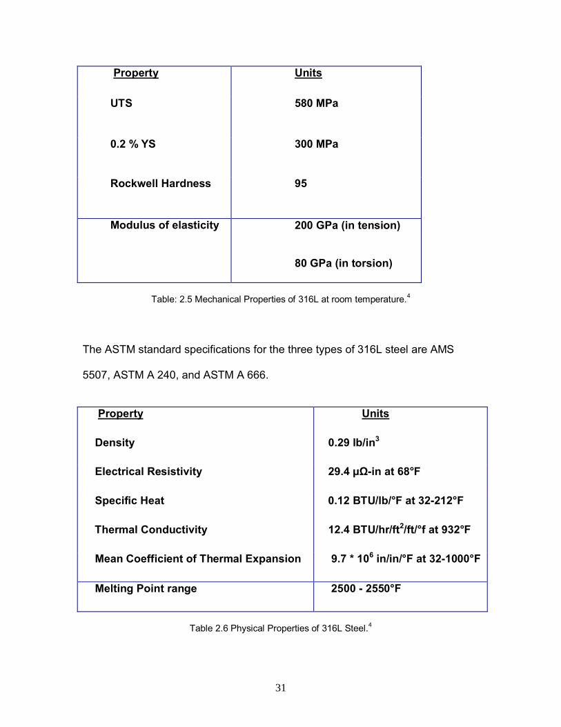
Table: 2.5 Mechanical Properties of 316L at room temperature.4
The ASTM standard specifications for the three types of 316L steel are AMS
5507, ASTM A 240, and ASTM A 666.
Property Units
Density 0.29 lb/in3
Electrical Resistivity 29.4 µ -in at 68°F
Specific Heat 0.12 BTU/lb/°F at 32-212°F
Thermal Conductivity 12.4 BTU/hr/ft2/ft/°f at 932°F
Mean Coefficient of Thermal Expansion 9.7 * 106 in/in/°F at 32-1000°F
Melting Point range 2500 - 2550°F
Table 2.6 Physical Properties of 316L Steel.4
32
Corrosive Resistance
316L has outstanding corrosion resistance. It remains unscathed
in a range of atmospheric environments and many corrosive media. Above
140°F, it is subject to pitting and crevice corrosion in warm chloride environments
and to stress corrosion cracking. It is considered resistant to potable water with
up to about .0101 lb/gal chlorides at room temperature reducing to about 0.005
lb/gal at 140°F.
Grade 316 steel is usually regarded as the standard marine grade
stainless steel, but it has been found that it shows not resistance to warm sea
water. It is subject to surface corrosion usually visible as brown staining
associated with crevices and rough surface finish in many marine environments.
Heat Resistance
Grade 316 shows good oxidation resistance in fitful service at
1598°F and in continuous service at 1697°F. It is not recommended to use 316
continuously in the range of 797-1580°F to prevent aqueous corrosion
resistance. Grade 316L is more resistant to carbide precipitation and can be
used in the above temperature range.
Heat Treatment
To improve the hardness of 316 steel, it is subjected to Annealing.
It is heated to a temperature range of 1850-2048°F and is cooled rapidly.
However, it is quite difficult to harden these grades by thermal treatment.
33
Welding
It shows excellent weldability by all standard fusion methods, both
with and without filler metals. Heavy welded sections in grade 316 require post-
weld annealing for maximum corrosion resistance. This is not required for 316L.
Grade 316Ti may also be used as an alternative to 316 for heavy section
welding. 316L steel is generally not weldable using oxyacetylene welding
methods. Special attention is necessary to prevent weld hot cracking by
formation of ferrite in the weld deposit. Grade 316 and 316L generally have
poorer weldability than grades 304 and 304L. The prime factor here is the
percentage composition of nickel. The high nickel content in these alloys requires
slower arc welding speed and more consideration to avoid hot cracking.
Machining
It tends to work harden if it is machined too quickly. For this
reason low speeds and constant feed rates are recommended. It is also easier to
machine compared to grade 316 due to its lower carbon content.
Hot and Cold Working
Grade 316L steel can be hot worked using most common hot
working techniques in the range of 2102-2300°F, and certainly should not be less
than 1706°F. Post work annealing should be carried out to induce maximum
corrosion resistance. Some of the most common cold working operations such as
shearing, drawing and stamping can be performed on 316L. Post work annealing
is carried out in order to get rid of the internal stresses.4

34
Applications:
316L finds its use in some of the following applications:
• Marine applications.
• Pharmaceutical applications.
• Architectural applications.
• Food preparation equipment particularly in harmful chloride atmospheres.
• Medical implants such as pins, screws.
• Orthopedic implants such as hip and knee replacements.
• Fasteners.4

35
CHAPTER 3 – DESIGN ASPECTS OF POT ROLLERS
3.1. Objective
The research objective is to find the best material for the zinc pot
bearing that can withstand the stresses and the misalignments and design an
appropriate bearing-housing system for the stabilizer roll. Most of the galvanizing
lines use the sleeve type bearings, with or without ceramic inserts. These inserts
incorporate for the large bearing clearances and misalignments simultaneously to
minimize the chance for roll stoppage. The Fig.3.1 shows the end of a hollow
stabilizer roll of about 8-inch diameter. The openings at the end of each roll play
a significant role allowing for the proper inflow and outflow of the molten zinc
from the roll causing uniform heat flow and reducing thermal stresses. The roll is
usually made of centrifugal cast low carbon stainless steel, with its surface
machined to maximize sheet traction. A hemispherical button at the shaft end, is
used for the thrust bearing, and is shown welded to the end of the shaft.5
Fig: 3.1 Stabilizer roll of about 8-inch diameter with cantilever shaft welded at each end arms.5
36
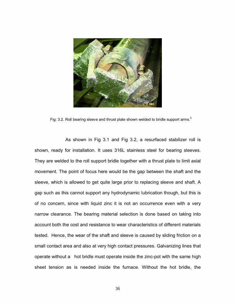
Fig: 3.2. Roll bearing sleeve and thrust plate shown welded to bridle support arms.5
As shown in Fig 3.1 and Fig 3.2, a resurfaced stabilizer roll is
shown, ready for installation. It uses 316L stainless steel for bearing sleeves.
They are welded to the roll support bridle together with a thrust plate to limit axial
movement. The point of focus here would be the gap between the shaft and the
sleeve, which is allowed to get quite large prior to replacing sleeve and shaft. A
gap such as this cannot support any hydrodynamic lubrication though, but this is
of no concern, since with liquid zinc it is not an occurrence even with a very
narrow clearance. The bearing material selection is done based on taking into
account both the cost and resistance to wear characteristics of different materials
tested. Hence, the wear of the shaft and sleeve is caused by sliding friction on a
small contact area and also at very high contact pressures. Galvanizing lines that
operate without a hot bridle must operate inside the zinc-pot with the same high
sheet tension as is needed inside the furnace. Without the hot bridle, the
37
stabilizer roll must also be able to steer the sheet by moving the bearing sleeves,
one in and the other one out. This alters the bearing sleeve alignment resulting in
an increased wear. Sheet steering produces axial thrust loading which may
cause failure of the thrust buttons. High and non-uniform bearing loading is
believed to be mainly responsible for short bearing life. From all the above
aspects, the following conclusions can be drawn:
• The usage of improved bearing materials, which are better able to cope
with this type of bearing load, is desirable.
• Contact pressure and the sleeve/shaft misalignment during the sheet
steering are the considered to be the main contributors to the short
bearing life.5
3.2. Wear Characteristics of Bearing Materials
“The four sectors: West Virginia University, Oak Ridge National
Labs, International Lead-Zinc Research Organization, industrial partners such as
steel makers, their materials suppliers and equipment producers all have been
involved in finding better materials for the continuous hot-dip galvanizing lines.
The effort was funded by the U.S. Department of Energy through the Office of
Industrial Technology. The research was to improve the performance of the
bearing materials supporting rotating components such as sink, stabilizer and
reflector rolls; minimizing corrosion of materials subjected to sliding contact,
nucleation and dross formation on molten metal bath hardware, especially on the
surface of the roll were it may cause cosmetic defects in the finished product.7
38
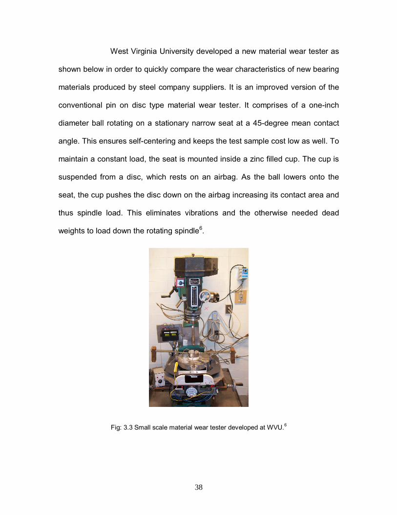
West Virginia University developed a new material wear tester as
shown below in order to quickly compare the wear characteristics of new bearing
materials produced by steel company suppliers. It is an improved version of the
conventional pin on disc type material wear tester. It comprises of a one-inch
diameter ball rotating on a stationary narrow seat at a 45-degree mean contact
angle. This ensures self-centering and keeps the test sample cost low as well. To
maintain a constant load, the seat is mounted inside a zinc filled cup. The cup is
suspended from a disc, which rests on an airbag. As the ball lowers onto the
seat, the cup pushes the disc down on the airbag increasing its contact area and
thus spindle load. This eliminates vibrations and the otherwise needed dead
weights to load down the rotating spindle6.
Fig: 3.3 Small scale material wear tester developed at WVU.6
39
An automated data acquisition system allows evaluating any
material sample of interest within a 24-hour day span. Jay Snider1 developed the
test procedure, which has become a routine operation. All the conventional roll
bearing materials have been tested such as 316 stainless steel and Stellite 6 in
addition to dozens of novel bearing materials supplied by steel company vendors
which includes MSA 2020 and ACD Ceramic Wearguard and coatings such as
laser-clad tungsten carbide in cobalt and nickel based alloy matrix composites.
Some of these new materials showed a significant improvement in their
respective wear performances under high contact pressures and velocities as
well. However, no one material provided orders of magnitude better performance
than the next best one. One series of tests performed with a 316 stainless steel
ball on a 316 stainless steel seat, covered a range in contact pressures from 25
to 100 psi and a range in contact velocities from 5 to 15 inch per second. These
series of tests were conducted with the test samples submerged in water to
eliminate the time required for sample heating, cooling and cleaning, as is
normally required to measure wear in molten zinc. The test data shown in Figure
4 all appear to fit a simple empirical equation as given below for wear rate, w, in
(inches per hour) as a function of contact pressure, pc, in (psi) and contact
velocity, Vc, in (inches per second) with wear rate equal:
5.0c
2c
7hour/inch V*p*10*4=w …….…….. (1)

40
A similar exponential wear rate sensitivity to contact pressure, pc,
was found using Stellite 6 on Stellite 6 test samples. Those tests were conducted
while submerged in a 460°C zinc-pot. The resulting wear-rate as a function of
contact pressure is shown in Figure: 3.4 and fits the empirical equation:
6.1cpw ………………… (2)
These two equations give an insight into the sensitivity of bearing material wear
rate to contact pressure, pc. It is observed that wear-rate is not proportional to
friction work done, as it is not proportional to the product of contact pressure
times contact velocity times the friction coefficient. The test results on all other
bearing materials clearly confirmed this observation.
Fig. 3.4 Wear rate of 316 Stainless Steel seat by a 316 Stainless steel ball sample submerged inwater.5

41
Fig.3.5 Wear rate of Stellite 6 seat by Stellite 6 Ball sample at 460°C.5
From the above mentioned test results, apparently high bearing
contact pressure is the most controlling parameter on bearing life. Therefore
developing a technique to decrease bearing contact pressure and simultaneously
preventing bearing miss-alignment with its associated point pressure may be
equally productive as the search for new materials”.6
42
3.3. New Design for roll bearing to reduce wear-rate
The test results conducted on various sample materials, it is
apparent that decreasing the bearing contact pressure by making the bearings
longer will have a significant impact on bearing life, provided one can assume
that the bearings remain perfectly aligned during all operations, including sheet
steering. An obvious way to reduce the contact pressure is by increasing the
shaft diameter and thus length. However, this decreases the ratio between the
sheet friction roll driving torque to the bearing friction roll stopping torque and is
therefore unacceptable.5
A recently filed patent application named “Bearing Life Extender
for Conveyor Type/Zinc-Pot Rolls” provides an apt solution for this problem.
According to it, the bearing length could be increased up to three fold without
increasing the shaft diameter and root bending moment. Moreover, it decreases
the shaft deflection, which itself also contributes to bearing wear, assures
optimum bearing alignment during sheet steering and allows using the bearing
sleeve itself to serve also as a thrust bearing. The figures used in the patent
application clearly depict the difference between the previously used
configuration (Figure: 3.6) and the modified design (Figure: 3.7).
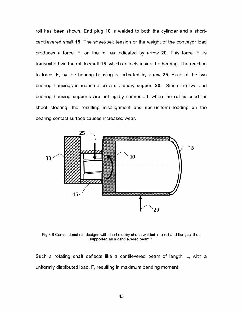
In contrast, the conventional roll design comprised of a rotating
shaft attached to the roller and held in place by a stationary bearing housing at
each end. The cylindrical roll 5 is often hollow and therefore only a section of the
43
roll has been shown. End plug 10 is welded to both the cylinder and a short-
cantilevered shaft 15. The sheet/belt tension or the weight of the conveyor load
produces a force, F, on the roll as indicated by arrow 20. This force, F, is
transmitted via the roll to shaft 15, which deflects inside the bearing. The reaction
to force, F, by the bearing housing is indicated by arrow 25. Each of the two
bearing housings is mounted on a stationary support 30. Since the two end
bearing housing supports are not rigidly connected, when the roll is used for
sheet steering, the resulting misalignment and non-uniform loading on the
bearing contact surface causes increased wear.
Fig.3.6 Conventional roll designs with short stubby shafts welded into roll and flanges, thussupported as a cantilevered beam.5
Such a rotating shaft deflects like a cantilevered beam of length, L, with a
uniformly distributed load, F, resulting in maximum bending moment:
20
5
30 10
15
25

44
2L*F
=Mmax …...………… (3)
and maximum deflection:
EI8L*F
=y3
max …………… (4)
The “Bearing Life Extender for Conveyor Type/Zinc-Pot Rolls" patent application
provides a solution for this crisis. It is based on using of a stationary shaft,
clamped at each end into the arms of the roll-supporting bridle. If the center
portion of the shaft between the two bearings were made thick and thus
essentially rigid, the bearing section would be loaded like a beam clamped at
each end. The resulting maximum bending moment in the shaft should be similar
to that of a beam, fixed at both ends, with a uniformly distributed load, F, and
length, L, as shown in Fig. 3.7.
6L*F
=Mmax ........…….….. (5)
and of maximum deflection:
EILFy
384**5 3
max =∆ ………….... (6)
Depending on the rigidity achieved at the end of each bearing, the maximum
bending moment might be reduced up to 6/2 = 3 fold, and the shaft deflection up
45
to 384/8 = 48 fold. Therefore a fixed shaft roller may be designed with bearings
that are both smaller in diameter and longer in length to improve their
performance. Reducing shaft deflection eliminates high pressure points and
contributes to increased bearing life.
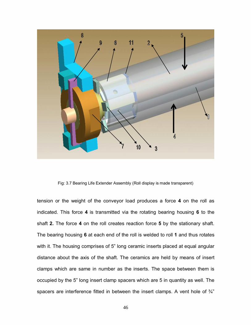
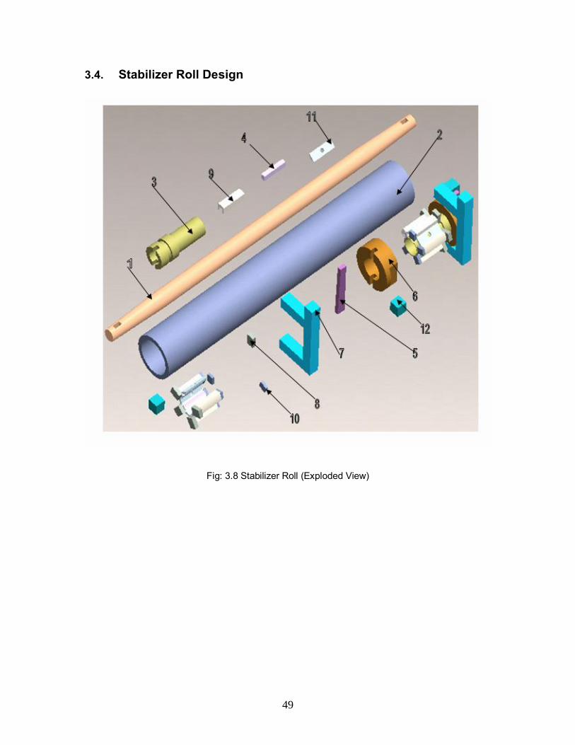
The 3D Fig.3.7 illustrates the differences between the
conventional and the modified roll equipment design. The major distinguishing
factor is that the 59 ” long 4” diameter roll 1 rotates about a stationary 72” long
3” diameter shaft 2, which has been rendered rigid on either side of the two
bearings as shown above. The display of the roll is made transparent. The roll 1
therefore has to be hollow, to accommodate such an internal shaft 2. Therefore,
again a sectioned view of the roll has been shown. The roll is a stepped one on
the inside to block the sliding of the inserts on the bearing sleeve. The sheet
46
Fig: 3.7 Bearing Life Extender Assembly (Roll display is made transparent)
tension or the weight of the conveyor load produces a force 4 on the roll as
indicated. This force 4 is transmitted via the rotating bearing housing 6 to the
shaft 2. The force 4 on the roll creates reaction force 5 by the stationary shaft.
The bearing housing 6 at each end of the roll is welded to roll 1 and thus rotates
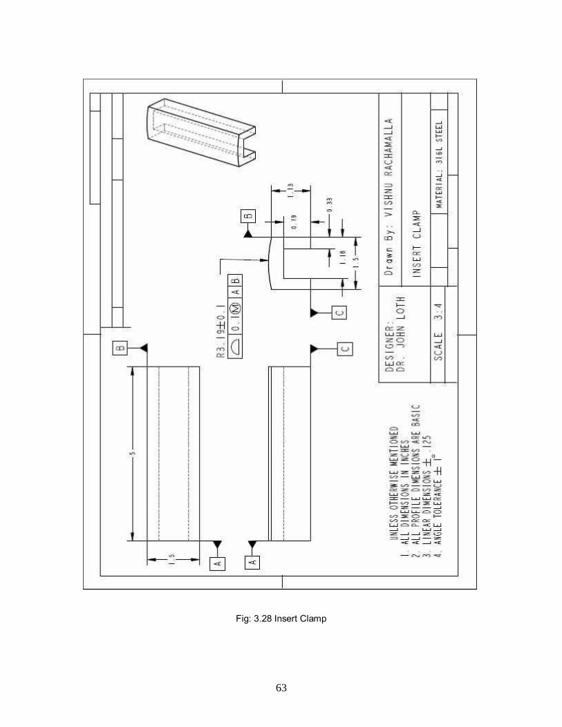
with it. The housing comprises of 5” long ceramic inserts placed at equal angular
distance about the axis of the shaft. The ceramics are held by means of insert
clamps which are same in number as the inserts. The space between them is
occupied by the 5” long insert clamp spacers which are 5 in quantity as well. The
spacers are interference fitted in between the insert clamps. A vent hole of ¾”
47
diameter is drilled through the centre of gravity of each spacer which enables
equal heat conduction throughout. This bearing housing accounts for the large
bearing-roller clearances. The stationary shaft 2 must be rendered rigid on either
side of the bearings. Therefore in between the two bearings, its diameter is
tapered along the bearing length. Outside the two bearings the shaft is clamped
securely to the roll support, such clamps are needed to render the shaft rigid
outside the two bearings. For maintenance purposes, the bearing housing 6 have
to be removable thus must be attached temporary to the roll. The bearing
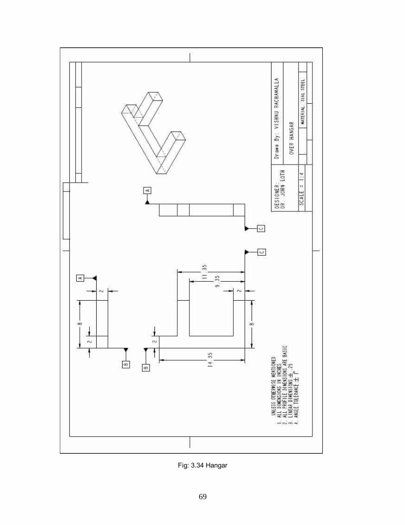
clamping hardware consists of an 8.5” diameter 3” thick collar 7 placed over the
bearing. A lip of 1” thickness and ” depth is made on the collar on four sides as
shown for an over hangar 8 which exactly sits on this collar lip. A keyway runs
through the shaft, bearing and the collar as shown. A tapered key 9 of 10” long
with a taper of ” taper on one side prevents the relative motion between the
shaft, the bearing and the collar. Further to hold the tapered key 9 in its place the
over hangar 8 is installed. To prevent the over hangar from falling off, ceramic
blocks of 2” thick are welded on to the hangar as shown. There are 4 blocks
altogether which act like roll assembly locks on either side of the roll. The shaft 2
should be stiffer and thus must be thicker in between the bearings, as indicated
by the taper it can also serve as a thrust bearing. Such a dual function applies to
most bearing types. Hence the bearing now accommodates for both the radial
and axial loads. By mounting the bearing housings 6 into the roller cylinder by
means of the inserts with the spacers in between, they will act like vanes of a
centrifugal pump and move liquid zinc radially through the holes 3 in them. This
48
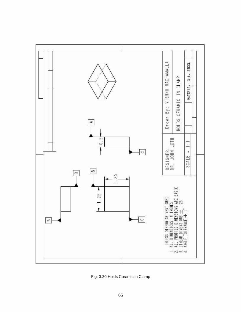
provides bearing cooling and improves the bearing lubrication. For holding the
ceramic inserts in the clamp, a 0.5” thick rectangular block 10 is welded onto the
roll and the bearing while mating the surface of the insert. There are 5 such
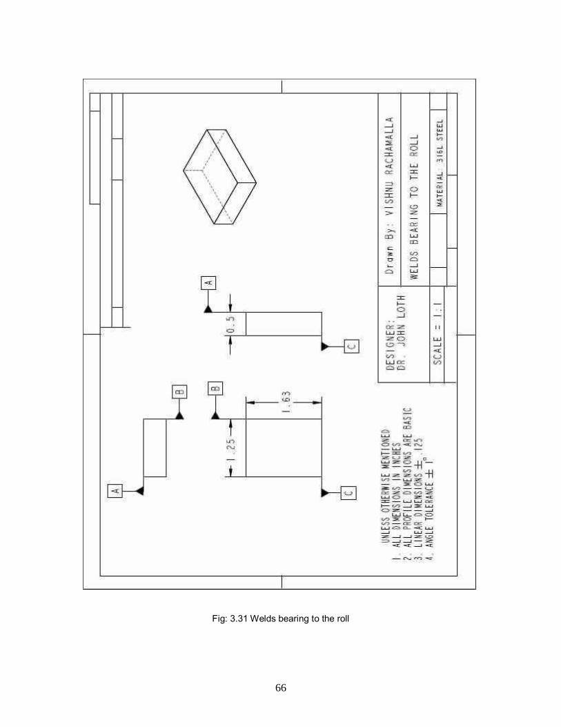
blocks stopping the inserts from sliding on the bearing on one side. On the other
side, we have another set of rectangular blocks 11 of different cross-section, 0.5”
thick though which are welded to the bearing radially on the inside and the insert
surface as well. There is a clearance of 1/16” between the stepped down roller
radial surface and the insert stopping rectangular block, also between the first set
of rectangular blocks and the stepped up bearing radial surface.
49
3.4. Stabilizer Roll Design
Fig: 3.8 Stabilizer Roll (Exploded View)
50
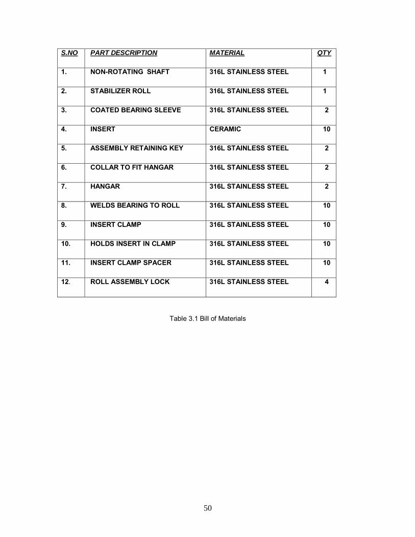
S.NO PART DESCRIPTION MATERIAL QTY
1. NON-ROTATING SHAFT 316L STAINLESS STEEL 1
2. STABILIZER ROLL 316L STAINLESS STEEL 1
3. COATED BEARING SLEEVE 316L STAINLESS STEEL 2
4. INSERT CERAMIC 10
5. ASSEMBLY RETAINING KEY 316L STAINLESS STEEL 2
6. COLLAR TO FIT HANGAR 316L STAINLESS STEEL 2
7. HANGAR 316L STAINLESS STEEL 2
8. WELDS BEARING TO ROLL 316L STAINLESS STEEL 10
9. INSERT CLAMP 316L STAINLESS STEEL 10
10. HOLDS INSERT IN CLAMP 316L STAINLESS STEEL 10
11. INSERT CLAMP SPACER 316L STAINLESS STEEL 10
12. ROLL ASSEMBLY LOCK 316L STAINLESS STEEL 4
Table 3.1 Bill of Materials

51
Fig: 3.9 Stabilizer Roll Assembly

52
Fig: 3.10 Side View of the Roll Assembly without Clamping
53
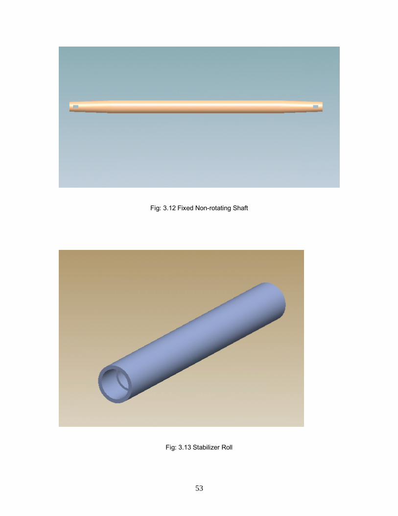
Fig: 3.12 Fixed Non-rotating Shaft
Fig: 3.13 Stabilizer Roll
54
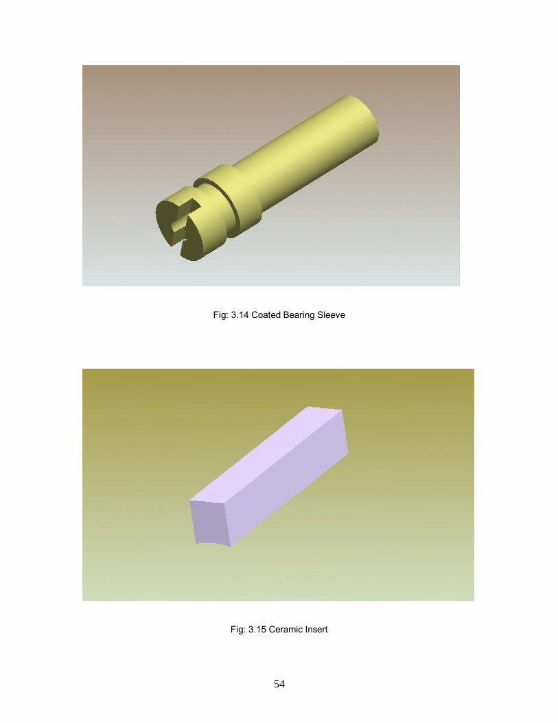
Fig: 3.14 Coated Bearing Sleeve
Fig: 3.15 Ceramic Insert

55
Fig: 3.16 Insert Clamp
Fig: 3.17 Ceramic Clamp Spacer
56
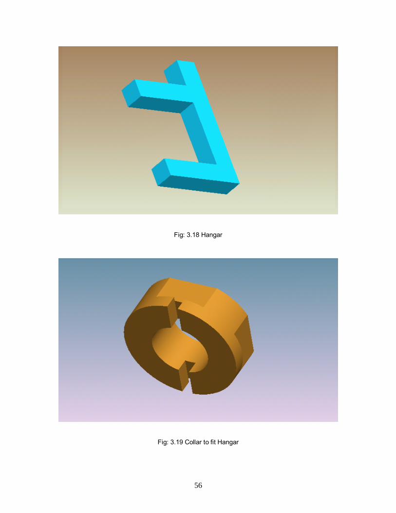
Fig: 3.18 Hangar
Fig: 3.19 Collar to fit Hangar

57
Fig: 3.20 Welds Bearing to the Roll
Fig: 3.21 Holds Ceramic in Clamp
58
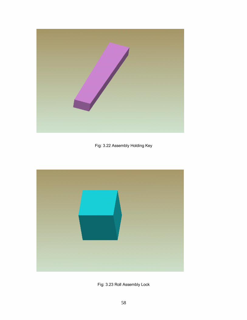
Fig: 3.22 Assembly Holding Key
Fig: 3.23 Roll Assembly Lock

59
3.5. Dimensioned Drawing Views
Fig: 3.24 Coated Sleeve Bearing

60
Fig: 3.25 Fixed Non-rotating Shaft
61
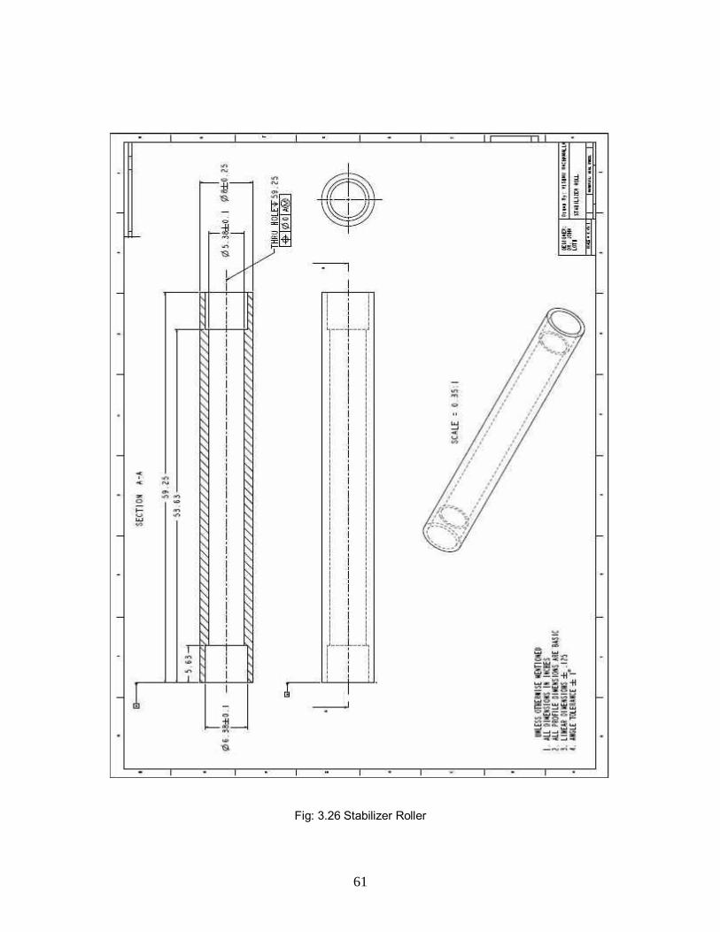
Fig: 3.26 Stabilizer Roller
62
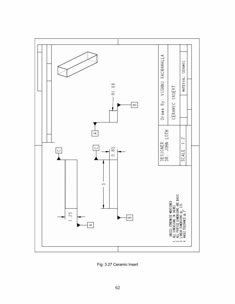
Fig: 3.27 Ceramic Insert
63
Fig: 3.28 Insert Clamp

64
Fig: 3.29 Insert Clamp Spacer
65
Fig: 3.30 Holds Ceramic in Clamp
66
Fig: 3.31 Welds bearing to the roll

67
Fig: 3.32 Collar to fit Hangar

68
Fig: 3.33 Tapered Key
69
Fig: 3.34 Hangar

70
Fig: 3.35 Roll Assembly Lock

71
3.6. DISCUSSION OF THE DESIGN
Through extensive testing of many bearing materials such as
316L Stainless steel, Stellite, and many other materials provided by the steel
vendors, it is determined that the bearing wear rate is proportional to the bearing
contact pressure to the power ranging from 1.6 to 2. The new bearing housing is
built inside the rollers, and then rotates with it. Thus both roller and bearing
housings rotate about a stationary shaft clamped at each end to the roll
supporting bridle. The bearing length now can be tripled without increased in
bending moment as compared to the conventional roller. Also, with the rotating
ceramic inserts being welded to the end of the roll, perfect bearing alignment can
be ensured. Finally, the drastic reduction in the bearing contact pressure could
increase the bearing life by at least five fold.

72
CHAPTER 4 – SUMMARY AND RECOMMENDATIONS
Due to bankruptcy of Weirton Steel and sale of the company in
2005, the on-line testing for the herein described bearing life extender is not
assured. Through the cooperative efforts between the following parties the cost
of a line trial would be shared by all. Weirton Steel intended to provide the roll
castings and perform the line trials; Vesuvius-Mc Danel supplied the 5x11/2 inch
size ceramic bearing inserts; Praxair Surface technologies volunteered the
bearing surface coatings with a 0.05” and 0.005” layer of laser clad tungsten
carbide on the inner and outer shells of the roll respectively. Petitto Mine
Equipment intends to make a reasonable bid for the roll manufacturing. The
stabilizer roll provided by Weirton steel is 8-inch in diameter. It rotates on a 4-
inch diameter stationary shaft. In the region of the two bearings, the shaft is
tapered down to 3-inch in diameter at the ends. The ends are rigidly clamped in
collars welded to the arms of the roll support bridle. Each bearing sleeve will
have five inserts 72° apart. The bearing sleeves are attached to the roller and
thus rotate with it. The 1/2-inch step between the 3-inch bearing and the 4-inch
shaft provides sufficient surface for the ACD Wearguard inserts to ride on,
thereby forming a thrust bearing. For the first line-trial, neither the bearing length
nor its diameter has been increased over that of the conventional roll. The
anticipated increase in bearing life will depend on: 1) Reduced shaft deflection
and thus more uniform loading, 2) Assured bearing alignment during steering and
thus more uniform loading, 3) Improved thrust bearing performance. Future tests

73
may use double the length of the bearing areas to demonstrate the advantage of
reducing bearing contact pressure.
The anticipated drawbacks of the fixed shaft design are: a) the
need to drain all the zinc from the inside of the roll when it is removed from the
zinc-pot otherwise it may solidify permanently within the shaft inside. b) The
presence of a stationary shaft inside the roller adds friction and may affect roller
stopping torque. West Virginia University is hopeful that the advantages listed
above will overshadow its shortcomings and the fixed shaft configuration may
significantly increase the time between overhauls.5
74
REFERENCES
1. Galvinfo Center Rev 2.1 August 2003, International Lead Zinc Research
Organization (ILZRO), details included in the Internet posting
www.steelmillsoftheworld.com/activities/datacenter.
2. Society of Automotive Engineers, Matzelle, Albert J, “Examination of
stress in sleeve bearing backs”, July 1981.
3. Don Renner, “Hands-On-Maintenance for Water, Wastewater Equipment”
October 1, 1998.
4. 316 Stainless Steel Data Sheet, details included in the Internet posting
www.aksteel.com/pdf/markets_products/stainless/austenitic/316_316L_Da
ta_Sheet.pdf.
5. Dr. John Loth, “Zinc-Pot Roll Bearing Design Modification for Increased
Life”, Galvatech 04’ Conference, April 4-7 2004. (Also in “Materials
Characterization “WIT Press 2004, ISBN: 1-85312-988-7).
6. Dr. James Snider II, “Zinc Pot Material Wear and Corrosion
Characterization”, PhD Dissertation, West Virginia University, WV USA,
December 2004.

75
7. Ryan Ware, “Design and construction of a Zinc Pot Bearing Material
Wearing Tester”, April 1, 2001 – March 31, 2002.
8. V.Parthasarathy,”Long term Performance of Pot Hardware in Continuous
Galvanizing Lines”, Master’s Thesis, West Virginia University, 2003.
9. Teck Cominco Metals Ltd, “Effects of bearing design on the wear of a
journal bearing sliding in the molten zinc”, 44th MWSP Conference
Proceedings , Vol.XL, pp 1285-1297, 02.

76
APPENDIX
Consider a stabilizer roll under a 500 pound load with bearings located at the end
of the tube, forming the roller surface. The roll acts like a beam with uniformly
distributed load with the supports not at the end, but as shown in the Fig 3.36.
The length over which the bearing supports the roll is 55/8". Hence, the deflection
can be calculated assuming the supports at L= half of 55/8". This gives a more
appropriate estimate of the deflection.
Fig: 3.36 Uniform Load acting on the Stabilizer Roll
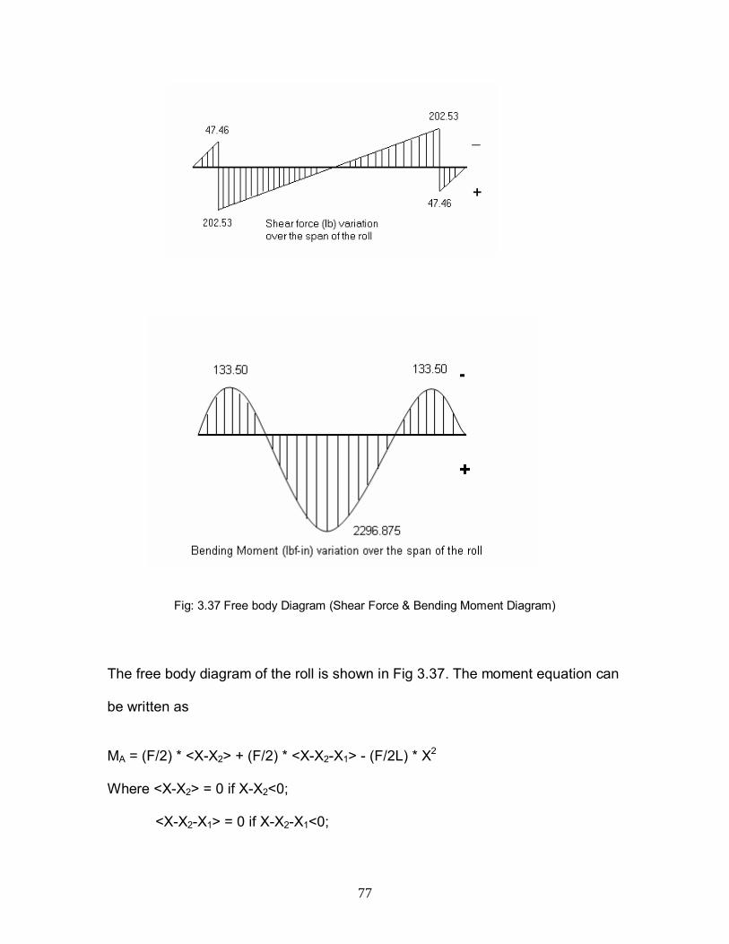
77
Fig: 3.37 Free body Diagram (Shear Force & Bending Moment Diagram)
The free body diagram of the roll is shown in Fig 3.37. The moment equation can
be written as
MA = (F/2) * <X-X2> + (F/2) * <X-X2-X1> - (F/2L) * X2
Where <X-X2> = 0 if X-X2<0;
<X-X2-X1> = 0 if X-X2-X1<0;

78
For F = 500 lbf, L = 59 ”, X1 = 48”, X2 = 55/8",
The value of the maximum shear force is
F*X1/ (2*L) = 202.53 lbf
Due to the overhang, the negative shear force component is
F*X2/ L = 47.46 lbf
The maximum bending moment occurs at the centre
F*(X12-4X2
2)/ (8*L) = 2296.875 lbf-in
At the supports it is
(F*X22)/ (2*L) = 133.50 lbf-in.
To find the maximum deflection for varying value of X2 (bearing length):
According to beam bending theory,
E*I*(d2y/dx2) = - MA = (F/2L) * X2 - (F/2) * <X-X2> - (F/2) * <X-X2-X1>
Where X = 0 to L
E*I*(dy/dx) = (F/2L) * (X3/3) – (F/4) * <X1-X2>2 – (F/4) * <X-X2-X1>2 + C1
E*I*y = (F/24L) * X4 – (F/12) * <X-X2>3 – (F/12) * <X-X2-X1>3 + C1X + C2
At X = L/2 = (X1/2 + X2), dy/dx = 0; solve for C1
At X= X2; y = 0; solve for C2
At X = L/2; y = ymax
The final equation after including the obtained values of C1 and C2 is
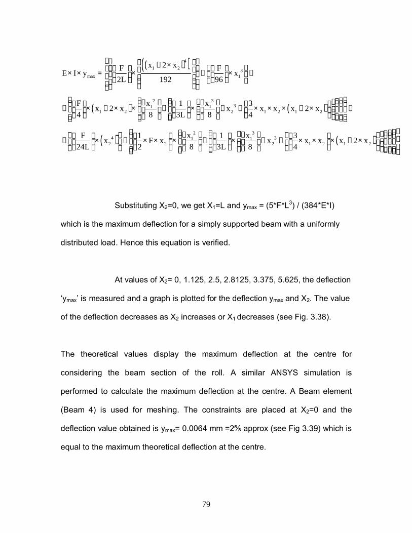
79
Substituting X2=0, we get X1=L and ymax = (5*F*L3) / (384*E*I)
which is the maximum deflection for a simply supported beam with a uniformly
distributed load. Hence this equation is verified.
At values of X2= 0, 1.125, 2.5, 2.8125, 3.375, 5.625, the deflection
‘ymax’ is measured and a graph is plotted for the deflection ymax and X2. The value
of the deflection decreases as X2 increases or X1 decreases (see Fig. 3.38).
The theoretical values display the maximum deflection at the centre for
considering the beam section of the roll. A similar ANSYS simulation is
performed to calculate the maximum deflection at the centre. A Beam element
(Beam 4) is used for meshing. The constraints are placed at X2=0 and the
deflection value obtained is ymax= 0.0064 mm =2 approx (see Fig 3.39) which is
equal to the maximum theoretical deflection at the centre.
( )( )
( ) ( )
41 2 3
max 1
2 331 1
1 2 2 1 2 1 2
x 2 xF FE I y x2L 192 96
x xF 1 3x 2 x x x x x 2 x4 8 3L 8 4
F24L
+ × × × = × − × + + × + × × − × + + × × × + × −
−
( ) ( )2 3
4 31 12 2 2 1 2 1 2
x x1 1 3x F x x x x x 2 x2 8 3L 8 4
× − × × × − × + + × × × + ×

80
The results of the maximum deflection values for X2 = 0, 1.40625, 2.8125,
4.21875, 5.625 for the roll obtained from ANSYS simulation & theoretical
equation are plotted in the graph (see Fig 3.41). The roll is meshed using the 3D
beam element Beam4. The deflection values from the ANSYS simulation can be
compared to that obtained on the roll experimentally.
Fig: 3.39 Maximum deflection in ANSYS (beam elements) at X2=0 (in mm)

81
Fig: 3.40 Maximum deflection in ANSYS (beam elements) at X2=5.625 (in mm)
Fig: 3.41 Comparison of Maximum Deflection values in ANSYS & Theoretical Equation (in inches)
0
0.00005
0.0001
0.00015
0.0002
0.00025
0.0003
0 2 4 6
Bearing Length (in)
Ym
ax (i
n)
TheoreticalAnalytical

82
Critical Speed of the Stabilizer Roll
It is the speed at which the roll would become dynamically unstable resulting in
strong vibrations. The critical speed of the Stabilizer roll can be calculated as:
c = (pi/ X1)2 * (D/4) * (g*E/ )0.5
Where,
c = Critical Speed
X1 = Distance between the bearings = 48 in.
D = Diameter of the roller = 8 in.
g = Acceleration due to gravity = 9.8 ms-2 = 385.8 in/sec2
E = Modulus of Elasticity = 30 E6 lb/in2
= Density of 316L Stainless Steel = 0.282 lb/in3
The value of the critical speed is obtained as 8792 rad/sec.
Hence the critical velocity would be V = r * c = 35168 in/sec, where r = radius of
the roll (4 in.)
The maximum sheet velocity is 110 in/sec (see Fig 1.2) for Line # 5 at Weirton
Steel. Even if the roll rotates about the same speed as the sheet, it is much lower
than the critical speed.