a model-driven traceability framework for software product
TRANSCRIPT

HAL Id: hal-00668175https://hal.inria.fr/hal-00668175
Submitted on 9 Feb 2012
HAL is a multi-disciplinary open accessarchive for the deposit and dissemination of sci-entific research documents, whether they are pub-lished or not. The documents may come fromteaching and research institutions in France orabroad, or from public or private research centers.
L’archive ouverte pluridisciplinaire HAL, estdestinée au dépôt et à la diffusion de documentsscientifiques de niveau recherche, publiés ou non,émanant des établissements d’enseignement et derecherche français ou étrangers, des laboratoirespublics ou privés.
A model-driven traceability framework for softwareproduct lines
Nicolas Anquetil, Uirá Kulesza, Ralf Mitschke, Ana Moreira, Jean-ClaudeRoyer, Andreas Rummler, André Sousa
To cite this version:Nicolas Anquetil, Uirá Kulesza, Ralf Mitschke, Ana Moreira, Jean-Claude Royer, et al.. A model-driven traceability framework for software product lines. Software and Systems Modeling, SpringerVerlag, 2010, 9 (4), pp.427–451. �10.1007/s10270-009-0120-9�. �hal-00668175�
The Journal on Software and Systems Modeling manuscript No.(will be inserted by the editor)
A Model-Driven Traceability Framework for Software Product Lines
Nicolas Anquetil1, Uira Kulesza2, Ralf Mitschke3, Ana Moreira2, Jean-Claude Royer1, Andreas
Rummler4, Andre Sousa2 ⋆
1 ASCOLA, EMN-INRIA, Nantes, France2 CITI/DI/FCT, Universidade Nova de Lisboa, Portugal3 TU Darmstadt, Germany4 SAP Research, Dresden, Germany
Received: date / Revised version: date
Abstract Software product line (SPL) engineering isa recent approach to software development where a setof software products are derived for a well defined targetapplication domain, from a common set of core assets us-ing analogous means of production(for instance, throughModel Driven Engineering). Therefore, such family ofproducts are built from reuse, instead of developed indi-vidually from scratch. Software product lines promise tolower the costs of development, increase the quality ofsoftware, give clients more flexibility and reduce time tomarket. These benefits come with a set of new problemsand turn some older problems possibly more complex.One of these problems is traceability management. Inthe European AMPLE project we are creating a commontraceability framework across the various activities of theSPL development. We identified four orthogonal trace-ability dimensions in SPL development, one of which isan extension of what is often considered as “traceabilityof variability”. This constitutes one of the two contribu-tions of this paper. The second contribution is the spec-ification of a metamodel for a repository of traceabilitylinks in the context of SPL and the implementation ofa respective traceability framework. This framework en-ables fundamental traceability management operations,such as trace import and export, modification, query andvisualization. The power of our framework is highlightedwith an example scenario.
1 Introduction
Software Product Lines (SPL) [45] are receiving increas-ing attention in software engineering. A software prod-uct line is a software system aimed at producing a set
⋆ The authors thank the members of the European AMPLEproject (www.ample-project.net)for their help in designingand developing the AMPLE Traceability Framework.
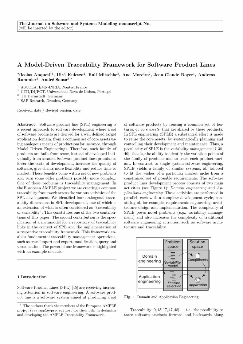
of software products by reusing a common set of fea-tures, or core assets, that are shared by these products.In SPL engineering (SPLE) a substantial effort is madeto reuse the core assets, by systematically planning andcontrolling their development and maintenance. Thus, apeculiarity of SPLE is the variability management [7,38,40], that is, the ability to identify the variation points ofthe family of products and to track each product vari-ant. In contrast to single system software engineering,SPLE yields a family of similar systems, all tailoredto fit the wishes of a particular market niche from aconstrained set of possible requirements. The softwareproduct lines development process consists of two mainactivities (see Figure 1): Domain engineering and Ap-plications engineering. These activities are performed inparallel, each with a complete development cycle, con-sisting of, for example, requirements engineering, archi-tecture design and implementation. The complexity ofSPLE poses novel problems (e.g., variability manage-ment) and also increases the complexity of traditionalsoftware engineering activities, such as software archi-tecture and traceability.
Fig. 1 Domain and Application Engineering.
Traceability [9,13,17,47,48] — i.e., the possibility totrace software artefacts forward and backwards along

2 Nicolas Anquetil et al.
the software lifecyle — is an important and practicalaspect of software engineering. The main advantages oftraceability are: (i) to relate software artefacts and corre-sponding design decisions, (ii) to give feedback to archi-tects and designers about the current state of the devel-opment, allowing them to reconsider alternative designdecisions, and to track and understand errors, and (iii)to ease communication between stakeholders.
Traceability is often mandated by professional stan-dards, for example, for engineering fault critical systems,such as medical applications. However, many existingtools and approaches are limited to requirements man-agement (for instance RequisitePro or works in [17,48]),rely on using and integrating various tools [5,13], pro-pose very limited analysis [40], and are not scalable.Additionally, industrial approaches and academic pro-totypes do not address end-to-end traceability yet, i.e.,spanning the full software engineering lifecycle. The useof traceability is considered a factor of success for soft-ware engineering projects. However, traceability can beimpaired by various factors ranging from social, to eco-nomical, and to technical [5].
In this article, we propose the AMPLE Traceabil-ity Framework (ATF), a framework that addresses theabove mentioned technical issues of traceability in theSPL context. ATF is designed to be open and generic,thus postponing the social and economic questions to theadoption of our solution in a specific context. ATF hasbeen developed using model-driven techniques, which of-fer good support to define an open and extensible ref-erence model for traceability. The implementation uti-lizes Ecore [15], a metamodel that was developed for theEclipse platform [14]. ATF is based on a process agnostictraceability metamodel that defines artefacts and hyper-links representing traces between artefacts. Through thehyper-link representation, the metamodel introduces m-to-n trace links as first class concepts.
By instantiating the metamodel, ATF can be config-ured to fit various development processes, as also sug-gested in [1]. In particular, ATF allows the definition ofhierarchical artefact and link types as well as constraintsbetween these types. Additional information related tothe trace context can be stored in properties associatedto artefacts and links. Such properties are useful to trackinformation related to specific software processes or torecord design rationales.
The ATF framework architecture is based on a meta-model implementation backed by a data base repositoryto store trace information. This core provides basic func-tionalities to initialize the framework and to access thetrace data. The implementation of the framework relieson the plugin architecture of the Eclipse platform to pro-vide extensibility for future applications. Building on theATF core, the framework provides a graphical front-end,which defines extension points to facilitate trace regis-tering, trace querying and trace viewing. The front-endallows building scenarios, which gather under a common
label, populators of the traceability repository, queriesand views. Such scenarios are dedicated to a specificanalysis task. The workflow is designed in an intuitivemanner, easily allowing users to combine various tools(queries, views, manual edition of the traceability links)to select and refine their trace link sets.
In addition to a generic framework for traceability, wepropose an application of traceability for software prod-uct line engineering and the accompanying instantiationof ATF. Existing propositions for traceability in SPLare examined, to identify the peculiarities of traceabilityin SPLE. These propositions include tools supportingtraceability in SPLE as well as existing approaches inacademia. From these studies we formulate four orthog-onal traceability dimensions in software product lines.These dimensions — refinement, similarity, time andvariability — are used to categorize traceability linksthat arise in general for any SPLE development process.Thus, we propose a base instantiation of ATF, where thebasic hierarchy of link types considers these dimensions.The instantiation provides a solid and clear frameworkfor traceability in SPLE and is, at the same time, exten-sible for further process specific link types.
In summary, the contributions of this paper are twofold:
– the identification of four orthogonal traceability di-mensions in SPL development;
– the implementation of a traceability framework basedon the specification of a metamodel for a repositoryof traceability links.
The remaining of this paper is organized as follows.Section 2 reviews existing traceability tools and discussestheir capacities to support software product line engi-neering. Section 3 analyzes the existing literature onSPLE traceability and concludes proposing four orthogo-nal traceability dimensions. Section 4 proposes the trace-ability framework requirements and follows by specify-ing the framework reference metamodel. Section 5 de-scribes the concrete implementation of the ATF frame-work, its core, front-end, and implemented plugins. Sec-tion 6 is devoted to a simple example to illustrate theconfiguration and the use of the ATF framework. Sec-tion 7 reviews some related work, mainly on traceabilitytools and model-driven engineering. Finally, Section 8concludes the paper finishing with future work.
2 Analysis of Existing Traceability Tools
The aim of the AMPLE project is to provide an SPLmethodology offering improved modularization of varia-tion, its holistic treatment across the life cycle, and easiermaintenance, through the use of Aspect-Oriented Soft-ware Development (AOSD) and Model-Driven Develop-ment (MDD). In the context of this project, we con-ducted a survey on industrial tools that support some

A Model-Driven Traceability Framework for Software Product Lines 3
Table 1 Alphabetical list of the main tools reviewed in the AMPLE’s tool survey.
Tool Provider Web site
CaliberRM Borland http://www.borland.com/us/products/caliber/rm.htmlDOORS Telelogic http://www.telelogic.com/products/doors/index.cfmGEARS BigLever Software Inc. http://www.biglever.com/solution/product.htmlPure::variants Pure-systems GmbH http://www.pure-systems.com/Variant Management.49.0.htmlRequisitePro IBM/Rational http://www.ibm.com/developerworks/rational/products/requisitepro/SCADE suite Esterel Technologies http://www.esterel-technologies.com/products/scade-suite/
TagSEAUniversity of Victoria& IBM T.J. Watson
http://tagsea.sourceforge.net/
TeamCenter Siemenshttp://www.plm.automation.siemens.com/en us/products/teamcenter/index.shtml
degree of traceability. The main tools reviewed are listedin Table 2. The goal of the survey was to investigate thecurrent features provided by existing tools to assess theirstrengths and weaknesses and their suitability to addressSPL development and maintenance. The tools were eval-uated in terms of the following criteria: (i) managementof traceability links, (ii) traceability queries, (iii) trace-ability views, (iv) extensibility, and (v) support for SPL,MD Engineering (MDE) and AOSD. These criteria areimportant for this kind of tools as they provide the basicsupport to satisfy traceability requirements (creation oftrace information and querying), easier variability man-agement, adaptability to projects specific needs [13], orconcerns regarding evolution of these tools and SPL de-velopment.
The “management of traceability links” criterion wasadopted to analyze the capacity of each traceability toolto create and maintain trace links (manual or automatic)and what kind of trace information is generated. The“traceability queries” criterion analyzes what searchingmechanism is available from the tools to navigate amongthe artefacts and respective trace links, varying fromsimple queries to navigate among the related artefacts,to more sophisticated queries that support advanced func-tionalities, such as coverage analysis or change impactanalysis. The “traceability view” criterion characterizesthe supported views (tables, matrix, reports, graphics)that each tool provides to present the traceability in-formation between artefacts. The “extensibility” crite-rion evaluates if any tool offers a mechanism to extendits functionalities or to integrate it with any other soft-ware development tools. Finally, the “support for SPL,MDE and AOSD development” criterion indicates if atool adopts any mechanism related to these new modernsoftware engineering techniques.
Table 2 summarizes key aspects of the evaluation ofsome tools. In terms of “links management”, the toolsallow defining them manually, but offer the possibilityto import them from other existing documents, suchas, MS-Word, Excel, ASCII and RTF files. CaliberRMand DOORS allow the creation of trace links betweenany kind of artefacts. RequisitePro focuses only on the
definition of trace links between requirements. For the“queries” criterion, RequisitePro provides functionali-ties to query and filter on requirements attributes. Cal-iberRM allows querying requirements and trace links.DOORS provides support to query any data on the arte-facts and respective trace links. Regarding advanced querymechanisms, CaliberRM allows detecting some inconsis-tencies in the links or artefacts definition, and DOORSoffers impact analysis report and detection of orphancode. The traceability tools offer different kinds of “views”,such as, traceability graphical tree and diagram, andtraceability matrix. All of them also allow navigatingover the trace links from one artefact to another. Interms of “extensibility”, CaliberRM allows specifyingnew types of reports and DOORS allows creating newtypes of links and personalized views. The three toolsalso provide support to save and export trace links datato external database through ODBC. DOORS integrateswith many other tools (design, analysis and configura-tion management tools). In the AMPLE project, we de-cided to design our tools around the Eclipse platform asit is an open infrastructure that allows to incorporateand integrate different tools supporting different activi-ties in software development and maintenance (editing,compiling, testing, debugging, . . . ). We noted that onlya few existing tools (e.g., DOORS or SCADE suite)had some sort of mechanism to support software de-velopment in open and extensible environment, such asEclipse. Finally, and as could be expected, these toolsdo not support “SPL, MDD or AOSD” technologies ex-plicitly, yet.
The conclusions that were drawn from our surveywere that none of the investigated tools had built-in sup-port for SPL development, and a vast majority of themare closed, so they cannot be adapted to deal with theissues raised by SPL. There is some recent progress inproviding traceability support for product lines. Two ofthe leading industrial tools in SPL development, GEARSand pure::variants, have defined some extensions to al-low integration with other commercial traceability tools.Pure::variants includes a synchronizer for both CaliberRMand Telelogic DOORS that allows the integration of func-

4 Nicolas Anquetil et al.
Table 2 Summary of the comparison of three requirement traceability tools according to the criteria chosen (see text).
RequisitePro CaliberRM DOORS
(i) Links ManagementManual Manual Manual + Import
Between requirements Complete life-cycle Complete life-cycle
(ii) QueriesQuery & filter on require-ments attributes
Filter on requirements &links
Query & filter on any data (in-cluding links)
- Links incoherence Impact analysis, orphaned code
(iii) ViewsTraceability matrix, trace-ability tree
Traceability matrix, trace-ability diagram, reports
Traceability matrix, traceabil-ity tree
(iv) Extensibility- - Creation of new type of links
Trace data saved w/ ODBC Trace data saved w/ ODBCIntegrates w/ > 25 tools (de-sign, text, CM, ...)
(v) SPL, MDD, AOSD Not Supported Not Supported Not Supported
tionalities provided by these tools with the variant man-agement capabilities of pure::variants. Similarly, GEARSallows importing requirements from DOORS, UGS Team-Center, and IBM/Rational RequisitePro. The evaluationof three of these tools is summarized in Table 2. How-ever, even the tools that may interact with pure::variantsor GEARS, handle traceability for traditional, single sys-tems. They all lack the ability to deal explicitly with SPLdevelopment specificities such as, managing and tracingcommonalities and variabilities for different SPL arte-facts, or dealing with change impact analysis.
To complete our analysis, we reviewed the academicapproaches supporting traceability for product lines orsystem families. Only three of them provide some sortof tool support [2,26,37]. (More details can be found inthe related work Section 7.) Mohan and Ramesh [37]present a framework and a knowledge management sys-tem to support traceability of commonalities and varia-tions. Ajila and Ali Kaba [2] use traceability to managethe software product line evolution based on an ad-hoctool set. Jirapanthong and Zisman [26,27] propose theprototype tool XTraQue to support traceability in prod-uct lines. The approach is based on a reference modelwith different kinds of artefacts and nine link types. Arule engine extracts automatically the trace information,comparing XML documents. None of these approachesprovides a clear and comprehensive view of the tracelinks in a SPL development. They are too rigidly con-nected with a specific software process. The ability totune the set of artefact types, the set of link types andthe software process is critical, since SPL approaches anddomain needs are very heterogeneous.
From this survey we conclude that a thorough anal-ysis of the dimension in SPL is needed, with specificemphasis on variability and versioning. As previouslynoted, a traceability tool for SPL needs to be configuredwith artefacts and link kinds associated to the softwareprocess, and as explained in [1], MDE seems a good tech-
nology to achieve this. Galvao and Goknil [20] presenta survey of traceability tools and approaches in MDE.The authors emphasize the importance of tool supportto automate traceability in MDE and discuss several de-ficiencies in this context. Many of these deficiencies areaddressed by our framework and will be discussed in Sec-tion 7. Nevertheless we need more than MDE to solvethe main difficulties related to traceability in SPL en-gineering. We envision an open traceability frameworkbuilt around a core repository to store trace informa-tion. Such a framework should allow easy connectionswith external tools, for instance feature model editors,configuration management systems, and textual docu-ments processing. It should also provide a basic querysystem to support more advanced functionalities such astrace metrics, graphical views, and execution of typicalscenarios, like change impact analysis or feature interac-tion.
3 Traceability in Software Product Lines
Traceability is typically thought to maintain links amongthe artefacts across the software development lifecycle.That is, it provides means to determine the relationshipsand dependencies between the software artefacts whichhelp support some software engineering activities suchas change impact analysis and software maintenance.
While traceability is an active field of research, thereseems to be little research on traceability for softwareproduct lines. It is generally accepted that for softwareproduct lines, one requires to deal explicitly with vari-ability traceability (e.g. [7,45]). This section analyzes theliterature on traceability and SPL with emphasis on var-ious dimensions. Our proposition argues for consideringfour orthogonal dimensions in software product line en-gineering. Amongst these relations, variability and ver-sioning are detailed since they are crucial and have tobe considered conjointly in SPL engineering.
A Model-Driven Traceability Framework for Software Product Lines 5
3.1 Software Product Line Traceability: ExistingPropositions
The difficulties linked to traceability in software prod-uct line are [26]: (i) there is a large number and het-erogeneity of documents, much more than in traditionalsoftware development; (ii) there is a need to have a ba-sic understanding of the variability consequences duringthe different development phases; (iii) there is a needto establish relationships between product members (ofthe family) and the product line architecture, or relation-ships between the product members themselves; and (iv)there is still poor general support for managing require-ments and handling complex relations.
For traditional software engineering, traceability istermed horizontal or vertical. Unfortunately, differentauthors switch the definition of horizontal and vertical([50], e.g. compare [24] and [44]). In this paper, we pro-pose to rename them with more suggestive names (seemore in Section 3.2). In CMMI (according to [24]), theterm vertical traceability refers to a link relating artefactsfrom different levels of abstraction in the software devel-opment process. We will call this refinement traceability.In CMMI, the term horizontal traceability refers to alink relating artefacts at the same level of abstraction.That would be the case, for example, for two software re-quirements presenting similarities. Such traceability al-lows one to find possible additional artefacts that wouldrequire the same maintenance operation than a givenartefact (because they are similar). We will call it simi-larity traceability.
Pohl, Bockle and van der Linden [45] recognize twotypes of variability traceability links. First, there is aneed to “relate the variability defined in the variabil-ity model to software artefacts specified in other mod-els, textual documents, and code.” [45, p.82]. These aretraceability links that will, typically, be restricted to thedomain engineering level, where variability is defined.At application engineering level, variability is reducedto concrete choices and there should not be any need forthis kind of traceability links, or they could be directlyinferred from the links at the domain engineering level.Second, we need to link “application artefacts to the un-derlying domain artefact” from which they are derived[45, p.34]. These traceability links will relate applicationengineering artefacts (in a given application, e.g., a soft-ware component) to domain engineering artefacts (in theproduct family). In their book, Pohl et al. appear to givemore attention to the first type of traceability than tothe second. However, both are needed.
Berg, Bishop and Muthig [7] propose the use of threetraceability dimensions: abstraction, refinement fromproblem space to solution space, and variability. How-ever, the first two seem highly correlated as abstractionlevel typically decreases when one goes from the speci-fication of the problem to the specification of the solu-tion (along a traditional development process). There-
fore, we think they could only consider two dimensions:one traces refinement of abstract artefacts to less ab-stract ones. This is probably the most traditional di-mension. The second traces variability and is specific tosoftware product line development. Berg et al. state that“The model [. . . ] explicitly and uniformly captures andstructures the variation points of each artefact and tracesthem to their appropriate dependent or related variationpoints in other artefacts”. They seem to refer to the firstkind of traceability identified by Pohl et al., between thevariability model and the other artefacts at the domainengineering level. There is no reference to the secondtype of variability traceability: from concrete artefact inan application to its underlying domain artefact.
Jirapanthong and Zisman [27] identified six groupsof traceability links and nine possible traceability links.However none of these nine links is explicitly classifiedin a group, thus greatly reducing the interest of the clas-sification. The nine traceability links are:
1. artefact a1 satisfies (meets the expectations and needsof) artefact a2: this seems to be a refinement link;
2. a1 depends on a2 and changes in a2 may impact a1:this may also be a refinement traceability;
3. a1 overlaps with a2: this could refer to a similaritybetween the two artefacts;
4. a1 evolves to a2, i.e., it is replaced by a2 in the de-velopment, maintenance or evolution: this seems tobe a configuration management traceability;
5. a1 implements a2: this seems to be a refinement trace-ability;
6. a1 refines a2: this seems to be a part-of traceabilitylink or a refinement traceability link;
7. a1 contains a2: this is a part-of traceability link;8. a1 is similar to a2: this is clearly a similarity trace-
ability link;9. a1 is different from a2: this is a complex relation that
relates two use cases implemented by two subclassesof the same class. It is not clear to us how to classifythis traceability link.
The problem with these links is that they seem veryspecific to some particular kind of artefacts (the authorsappear to work mainly with text documents); they arenot clearly orthogonal, and they do not clearly relateto a known traceability dimension, such as variability,refinement or similarity.
Mohan and Ramesh [38] take the problem from a dif-ferent perspective since they are interested in the knowl-edge required to best manage variability and to storetraceability links. They identify two practices of trace-ability: low-end practice and high-end practice. Thetraceability links commonly used in the low-end practicecorrespond to tracing the refinement of abstract arte-facts (such as requirements) to less abstract ones (suchas design artefacts). They may also include traceabilitylinks between artefacts at the same level of abstraction.These two are the traditional dimensions of traceability:

6 Nicolas Anquetil et al.
horizontal and vertical, respectively, that we call hereRefinement and Similarity. Traceability links in the high-end practice “include details about sources of variationsand their manifestations in design” which correspondsto the first variability traceability kind of Pohl et al. (re-lating variability to software artefacts realizing it). Mo-han and Ramesh also discuss what knowledge should berecorded along these traceability links, but this is outsidethe scope of this paper.
Finally, another work by the same authors (Mohan,Xu and Ramesh [39], and Ramesh and Jarke [48]) isof interest although it does not address traceability inthe context of software product lines. In that paper, theauthors argue for a better integration of traceability andsoftware configuration management. Their argument isthat both are intended to facilitate software maintenanceand contain complementary information on the currentstate of the system and how it came to that state.
Other papers propose other traceability classifica-tions, such as [32,43,48]. However, we did not includethem here as they do not consider software product lineengineering.
Thus, the first challenge we have is to clarify themain dimensions in SPLE. To get a comprehensive andorthogonal classification of trace link types would helpin understanding and managing traceability.
3.2 Traceability Dimensions for Software Product Lines
From our review of existing traceability tools (Section 2),as well as existing SPL traceability propositions (Section3.1), we conclude that there is still a need for a coherentand complete traceability classification scheme, to orga-nize the different types of traceability links required inSPL development. In this paper, we define a set of or-thogonal traceability dimensions to manage traceabilityin software product lines. The analysis is based on thetraceability needs identified in the literature.
We start by reusing the two traditional traceabilitydimensions. We then need a dimension to account forvariability traceability as suggested by many. Finally, webelieve that in software product lines, one needs tracingthe evolution of artefacts (i.e., Software ConfigurationManagement, see Section 5.4).
Let us first summarize the four dimensions beforediscussing them in depth. Figure 2 illustrates examplesof the four traceability dimensions.
Refinement traceability: relates artefacts from differentlevels of abstraction in the software development pro-cess. It goes from an abstract artefact to more con-crete artefacts that realize the first one. For example,a design model that refines a software requirement.Such links may happen in either of the two develop-ment stages of software product lines: domain engi-neering or application engineering.
Similarity traceability: links artefacts at the same levelof abstraction. For example, UML components andclass diagrams can specify the SPL architecture atdifferent levels of detail but at the same level of ab-straction (software design). The trace links definedbetween these artefacts can be used to understandhow different classes, for example, are related to spe-cific components (or interfaces) of the SPL architec-ture. The links are inside either of the two softwareproduct lines’ processes: domain engineering or ap-plication engineering.
Variability traceability: relates two artefacts as a directconsequence of variability management. For example,at the domain engineering level, a variability trace-ability link would relate a variant with the artefactthat “realizes” (or implements) it. Or, an applica-tion artefact (application engineering level) would berelated to its underlying reusable artefact at the do-main engineering level. For example, a use case modeland a feature model can be related to illustrate whichfunctional requirements are responsible to addressthe SPL common and variable features. Such trace-ability links allow understanding how SPL featuresare materialized in requirements and find potentialrelated candidates during a maintenance task.
Versioning traceability: links two successive versions ofan artefact.
Table 3 summarizes information on these four trace-ability dimensions.
The variability and versioning traceability dimensionsare the least common ones. So, let’s discuss them in moredetail.
3.2.1 Variability Traceability Dimension. As proposedby Pohl et al. [45] there are two main types of variabilitytraceability links. One could see them as subcategoriesin this dimension. The first relates a variant in the vari-ability model (therefore at the domain engineering level)to the artefacts that realize it, at all stages of the SPLdevelopment. Following Pohl et al. definition [45, p.83],we will call it realization. Although it is restricted to oneprocess (domain engineering), it is different from refine-ment because: (1) it is a direct consequence of explicitvariability management, whereas refinement traceabil-ity exists in traditional software engineering and there-fore has no direct relationship to variability; (2) it doesnot stem from the activities of the development processwhere one lowers progressively the level of abstractionof the artefacts produced; rather, it shows which SPLparts should be included or considered in a particularapplication if the variant is selected. This subcategoryof variability traceability is used in [7] and [38].
The second subcategory relates an artefact in the ap-plication to its underlying reusable artefact in the family.We propose to call this relationship use, because the ap-plication (product) actually uses a reusable artefact de-fined in the application family (product line). It is not a

A Model-Driven Traceability Framework for Software Product Lines 7
Fig. 2 Examples of the four orthogonal traceability dimensions (grey arrows) in the two processes of a software product line.
Table 3 Some information on the four traceability dimensions.
Dimension Occurs in which SPL engineering process?
Refinement Domain or Application EngineeringSimilarity Domain or Application EngineeringVariability/Realization Domain EngineeringVariability/Use Application Engineering to Domain EngineeringVersioning Domain or Application Engineering
refinement traceability either because: (1) it crosses theboundaries of software processes, and relates an artefactat the application engineering level to another artefact atthe domain engineering level; (2) one artefact is not lessabstract than the other; actually, they are the “same”artefact, one defined in the application family, the otherreused in the application. This relationship is identifiedby Pohl et al. but does not seem to have been used inother work. The use traceability relationship can be de-rived from the realization, but the opposite is generallynot true. The reason to consider it as a useful relation-ship is that computing it on-the-fly would be too expen-sive and several important trace functionalities are easilydefined using this relation.
3.2.2 Versioning Traceability Dimension. Software Con-figuration Management (SCM) is an important issue insoftware product lines, as one product family will in-clude concurrent applications from different stages (orages) of the whole family. All these applications are re-lated to the same family and therefore are derived fromthe same set of artefacts. Artefacts may evolve concur-rently both at the application engineering level (in anyof the applications) or at the domain engineering level.
Traceability is actually a central part of SoftwareConfiguration Management systems [13,39]. As the arte-facts stored in the SCM system evolve, the system itselfis able to trace the evolution of single artefacts. In addi-
tion, SCM systems are used for building configurations(baselines), for example as the basis for product deploy-ments. In general, SCM systems hold the possibility togroup versioned elements into any meaningful unit. Theinformation on the configurations provides traceabilityinto the different parts of the development process wherethese configurations are used.
However, SCM systems, such as, Subversion [11] andMicrosoft Visual SourceSafe [35], are limited to tracingthe evolution of files. These systems are either not at allconcerned with the dependencies that arise between thestored files and other artefacts in a software engineer-ing process, or only to a limited degree. Visual Source-Safe, for example, allows to trace which files are usedacross multiple projects, i.e., tracing the reuse of soft-ware components or implementation elements, but theydo not provide support to trace requirements or specificSPL features. Information of such interdependencies be-tween artefacts can be captured using traceability sys-tems/tools. However, these systems/tools are not con-cerned with the integration of versioning information.The importance of integration between SCM and trace-ability tools is also recognized in [39] as cited in Section3.1.
The integration between SCM and traceability sys-tems must be considered in both directions. Either sys-tem can benefit from the information provided by the
8 Nicolas Anquetil et al.
other. The following two key scenarios demonstrate theusage of integrated information.
The first scenario is to use traceability informationprovided by the SCM system for enhanced impact analy-sis. This is especially important during software mainte-nance. In such scenario, errors must be corrected; trace-ability in the versioning dimension can be used for im-pact analysis regarding the other versions of a productthat must be corrected. In software product line engi-neering, the complexity of this impact analysis is en-hanced even further as also other members of the prod-uct line and their respective versions must be identifiedusing the impact analysis.
The second scenario is to aid the construction ofbaselines, which is one of the major responsibilities ofSCM systems. Baselines are configurations of artefactsthat are, for example, a beta release, a stable release, or arelease delivered to customers. By using backward trace-ability information, this process may be enhanced withinformation regarding implemented requirements or in-cluded features. Thus, developers are able to determinethe correctness and consistency of the baselines.
The traceability information that stems from the base-lines is very important during product line maintenance.The additional traceability information, that relates theartefacts in the versions as they were used for a release,may be used to recover the state of the software thatwas delivered to the customer. Traceability informationregarding implemented features of the product line canbe retrieved and, thus, provide a higher level of under-standing regarding the specific baseline.
4 A Model-Driven Traceability Framework to
SPL
Our goal is to implement a traceability framework thataccepts the four dimensions of traceability. However, thereis a number of additional requirements that this frame-work should respect. This section reviews these require-ments, then describes the metamodel designed to answerthem and from which the traceability framework will bebuilt.
4.1 Traceability Framework Requirements
Traceability still faces many challenges in software prod-uct line engineering, in particular, the heterogeneity andnumber of artefacts, the increased complexity of arte-facts, and the diversity of software processes. Most cur-rent tool support is too specific to deal with these newchallenges (see Section 2). For example, commercial toolsdo not deal with new artefacts [13] and abstractions,such as variability points and variants, or they do noteasily inter-operate with other tools [1], such as feature
models. Although we focus here only on technical prob-lems, there are also social, communication and economicproblems involved that will need to be tackled.
In a study of the factors influencing traceability adop-tion, Ramesh [47] identifies two main groups of trace-ability users, low-end (who are not using or only startedto use traceability) and high-end (who have been usingtraceability for at least five years), which have differ-ent objectives and practices. This paper describes fourfactors for adopting and using traceability: (i) developmethods, (ii) acquire tools, (iii) develop tool, and (iv)change system development policies. Acquire tools anddevelop tools are the most relevant factors to our currenttask on traceability tool support. Mohan and Ramesh[38] also present key recommendations for successful trace-ability of variations. From the technical perspective, wecan note their recommendations: focus the documenta-tion on variation points, provide an integrated environ-ment, and propose a comprehensive traceability solution.From these indications, we decided to develop our owntraceability framework.
Therefore, this framework must attend to a numberof requirements that we found important:
– it should be process agnostic, not imposing any arte-fact or link type;
– it should be flexible, for example by allowing easyincorporation of new artefact types or link types;
– it should be scalable and deal with real life softwareproduct line;
– it should be extensible, allowing the creation of newways to register, retrieve, manipulate and otherwisemanage the traceability links;
– it should support m-to-n traceability links, as op-posed to only 1-to-1 links, that most of the existingtools work on.
Being process agnostic is a fundamental requirementof any traceability tool [13]. There are too much differ-ent processes, each with specific artefact types to commitwith such an early decision on this issue. Except for thework of Moon and Chae [40], all other approaches seemto have a predefined set of artefacts types which cannotbe adapted to other development contexts or user needs.Furthermore, according to Ramesh and Jarke [48] allow-ing an hierarchy of artefact types is useful to tune thegranularity level of the trace. The same goes with linktypes. We therefore need to accept creation of new kindsof artefact types and link types, these being possibly or-ganized in hierarchies of types.
Flexibility is required to ensure that new artefact orlink types will easily be created. For example, if Moonand Chae [40] need to create new types of artefacts, theyneed to modify their metamodel, which is not an easytask. We need a solution where new artefact and linktypes can be created, if possible directly in the repos-itory framework. Considering the different traceability

A Model-Driven Traceability Framework for Software Product Lines 9
dimensions encountered in SPL development, this needfor flexibility is still more critical.
Regarding scalability, we saw in Section 2 that com-mercial tools do not deal with software product line en-gineering. Unfortunately, most of the research tools onlyaccept toy examples. Although we do not aim at compet-ing with the commercial tools, the presence of industrialpartners on the AMPLE project makes it an obligationfor us to come with solutions that have some relevanceto them. This includes being able to deal with hundredsof thousands of artefacts and links. For example, severalapproaches or tools are using an XML support to docu-ment and/or trace links (e.g., [26,49]). There have beenconcerns in the past on whether XML scales up nicely ornot (e.g., [34]). In need for a definite answer, we decidedto store the data in a relational database.
The traceability framework should also be easily ex-tended to adapt to new needs, such as creating newqueries, new ways to visualize the results, and inter-operate with other existing tools. Again, a solution likethe one proposed by Moon and Chae [40], where a meta-model needs to be modified to change the framework,does not answer our requirements. We would rather fa-vor a solution that allows “traditional” (non MDE) pro-gramming extension. MDE is still not widely used inmany real world settings and we feel that imposing it tothe user of our framework could create a barrier to itsadoption. This does not mean we rule out MDE. Actu-ally, there seems to be a general tendency to use MDEfor traceability tool support ([1,19,28,40]). We believethat MDE provides flexibility and easier evolution man-agement for the framework. Therefore, we will adopt it.Nonetheless, we do not want to impose the use of MDEto the user of our framework as this technology is notalways a practical solution in real world environments.
Finally, dealing with m-to-n traceability links was setas one of our goals. M-to-n links are required as recog-nized in Pohl et al. [45, p.70] or Berg et al. [7], however,from the evidences published, it seems that all research— including Berg et al. [7] — only deals with 1-to-1traceability links. If m-to-n links are more difficult torepresent graphically (see Section 5.3.3), they allow torepresent more accurately the reality of the traceabilitylinks, particularly links such as refinement traceability.In case of SPL development, these kinds of links can con-tribute: (i) to reduce the total amount of trace links, thushelping the tool scalability; and (ii) to represent moreconcisely a set of trace links between variability (varia-tion point, variants) and its respective artefacts relatedto it in the application engineering. When representingthe causality between, for example, a requirement andseveral design artefacts, it is important to know all thedesign artefacts that stem jointly from the same require-ment so as to understand them jointly. Representing m-to-n links also diminish drastically the number of re-quired links and therefore simplifies the representation.
4.2 Traceability Framework Metamodel
From the previous requirements, we elaborate a meta-model for traceability links. The goal of the metamodelin our traceability framework is to provide a uniformand reusable structure for defining trace models duringsoftware product line development. We studied some ofthe existing traceability metamodels of the literature.One important piece of inspiration was the ModelWaretraceability metamodel [46]. We reuse the idea that themodel must be as simple as possible and the complexlogic for analysis shifted to the tool support. There ex-ists a large body of knowledge related to metamodelsfor traceability [3,4,9,10,16,19,26,28,48,49,55]. A va-riety of approaches for storing traceability informationare proposed: database schema [6], XML schema [26,49]or metamodels [19,28,46]. We choose an agnostic meta-model representation since we want to address traceabil-ity when aspect-orientation, model-driven developmentand software product line engineering are used in con-junction.
We said that we want the user to be able to definethe kinds of artefacts or links he needs. Thus, the meta-model must represent not only artefacts and links butalso kinds of artefacts and kinds of links. These typescan be organized in hierarchies. Another point is thatwe want to deal with m-to-n links, that is to say, withpossibly multiple sources and multiples targets.
Our framework must be configured before usage, whatimplies taking into account additional constraints. Forinstance, a user may need to define a kind of link, sayUC-refinement, which is only existing between a usecase and an UML sequence diagram. Thus, we introducethe notion of scope and scope area to cope with this ad-ditional constraint. As in [33], we consider that manyinformation can be attached to artefacts and links. Ourinformation system must be sufficiently rich to representinformation related to the tracing context, for instancerationale for design decisions, variant choices or otherinformation. Thus, we provide the concepts of artefactsand links with a dictionary of properties and so-calledcontext objects that might serve as a container for morecomplex information.
The metamodel for traceability is depicted in Fig-ure 3. This metamodel is designed in MOF 2.0 [42], asit facilitates the integration of tools and languages de-veloped in AMPLE by providing easy mapping/transfor-mation to Ecore metamodel from Eclipse Modeling Frame-work (EMF). EMF is the model-driven framework thatwas adopted to implement our traceability framework.This traceability metamodel basically definesTraceableArtefacts and TraceLinks between theseartefacts as fundamental elements. The TraceableArte-facts are references to actual artefacts that live in somekind of source or target model or just arbitrary elementscreated during the development phases of an applicationlike, a requirement in a requirements document. Such

10 Nicolas Anquetil et al.
traceable artefacts are named elements that contain, inaddition, an URI, that denotes the location of the actualelement and the way to access it (e.g., a text document,an UML model, an elements inside an UML model, etc.).An example for such an URI could be prj://crm/mo-
dels/datamodel.ecore/Customer, denoting a model el-ement Customer in a model datamodel in the folder mod-els of a project crm that is made accessible from somecompany-wide project repository denoted by the URIprotocol prj. A traceable artefact in the repository canplay the role of source artefact and target artefact, simul-taneously. For instance, an architectural artefact couldbe a target traceable artefact when considering a require-ments to architecture mapping, and a source traceableartefact when considering an architecture to implemen-tation mapping.
Fig. 3 The ATF Traceability Metamodel.
A TraceLink represents explicitly trace relationshipsbetween a set of source artefacts and set of target arte-facts. This enables the management of traceability mod-els as a set of annotated, directed, bi-partite hypergraphsG = (V1 +V2, E), where V1 is the set of source artefacts,V2 is the set of target artefacts, and E is a set of anno-tated arcs from P(V1) to P(V2). The annotations serveto distinguish different kinds of relationships betweensource and target elements. To allow a more fine-grainedcontrol of the traceability relationships, hyperlinks canalso be decomposed into a set of traceability links, whichrepresents a relationship (e.g., a dependency) betweenone source artefact and one target artefact.
Each TraceableArtefact and each TraceLink istyped to denote the semantics of the element itself. Thistype is expressed via a TraceableArtefactType and aTraceLinkType, respectively. Each type exists exactlyonce in the appropriate domain. However, a type is nota singularity within such a domain, instead it may shareaspects with other types. For this reason, types mayform an inheritance hierarchy. An example would be an
UML Diagram type, which can be specialized into a de-rived UML Sequence Diagram type. Derived types shareproperties with their parent types, just like classes inobject-oriented languages. Multiple inheritance is possi-ble to generalize this concept. Defining a type hierarchyenables generalized reasoning over trace data, i.e., tak-ing UML diagrams into account, regardless whether theyare sequence or activity diagrams (given the appropriatetype for sequence and activity diagrams are defined assubtypes derived from a UML diagram type).
Links between artefacts can be established in an arbi-trary manner. However, for a domain, this is usually notdesirable, as particular links of a certain type only makesense as relationships between artefacts of certain types.For example, a UML Classifier may not contain an UMLClass Diagram, while the opposite is of course valid. Toallow such consistency checks, the so-called Scopes andScopeAreas have been introduced. Each TraceLinkType
has one scope, in which it is valid. The scope itself con-tains a number of scope areas. A scope area defines whichartefact types are allowed as types for link source andlink targets. In order to ease the creation of such validityscopes for link types, these types derive their scope fromtheir base types according to the inheritance hierarchyexplained in the previous paragraph.
Artefacts and links form a graph which representsthe relations between elements that are produced dur-ing the development of some arbitrary software prod-uct. However, knowledge about these relations alone ismost probably not sufficient during the reasoning pro-cess over the trace graph. For this reason all elementsof the trace graph may be annotated with additional in-formation. The most simple way of annotating elementsis by using key-value pairs. Appropriate keys and valuesmay be created for each artefact and link (and also fortypes). As an example, the creator and the creation dateof some model may be attached to the artefact referenc-ing this model. A creation date may also be attached tosome link of type transforms to to denote the point oftime at a model transformation has taken place. How-ever, we are aware that simple key-value pairs may beused to capture additional trace information, but usingthis possibility only may not be sufficient in some cases.For this reason each element in the trace graph may ref-erence an optional TraceContext. This is a nothing elsethan an empty element in the metamodel from whicha user can derive and extend the metamodel appropri-ately. This way, arbitrary complex information can beattached to elements in the trace graph, like the con-text in which artefacts have been created and relationsamong them are valid (just as the name indicates).
Our metamodel is very similar to the one proposedby Walderhaug et al. [55]. Both have traceable artefactsand traceable artefact types, what we call trace linksand trace link types are relation traces and relation tracetypes in Walderhaug et al.. Three differences stand out.First, our scope is more general than the mechanism pro-

A Model-Driven Traceability Framework for Software Product Lines 11
posed by Walderhaug et al. that allows only one type oftraceable artefact as source of a trace link type and onetype of traceable artefact as target. Second, Walderhauget al. propose an artefact trace that appears to allowautomatic trigger of actions when traces are created. Fi-nally, we allow representing the context of a trace or anartefact to register such things as a design rationale forexample.
5 The Framework
The overall design of the ATF framework is depictedin Figure 4. We built it as an extension to the Eclipseframework. This gives us a strong platform on which tobuild our tools and it is a good solution to allow easyintegration in a typical working place. The core part ofour ATF framework is the traceability information sys-tem which is based on a metamodel (see Section 4.2)and a repository (see Section 5.1). The front-end of ATF,in Section 5.2, allows the user to interact more friendlywith the core ATF and define procedures and extensionpoints to add new facilities to the framework. Differentextensions to the framework started to be implemented,some of which will be introduced in Section 6. Finally,one important piece is the interaction with the configu-ration management system which provides for versioningtraceability. This is described in Section 5.4.
Fig. 4 Overall ATF Design
5.1 ATF Core
The core of the framework is centred around the meta-model described in Section 4.2. The core consists of func-
tionality to initialize the framework and to grant accessto the contained trace data.
The trace data is held in a trace repository, whichcontains all the specific data necessary to a certain usecase for tracing activities. In particular, it contains: a setof artefact and link types, as well as their allowed rela-tionships among each other (in form of scope and scopeareas as explained at the end of Section 4.2); artefactsand links as relations between more appropriate proper-ties; and, context objects that form the rationale for theexistence of all trace elements.
The main entrance point(s) to the framework is aset of manager classes. Each trace repository is con-trolled by a so-called RepositoryManager, which grantsaccess to other managers tailored to various facets ofthe work with such a repository. Namely these are aPersistanceManager, a TypeManager, an ItemManager,an ExtractionManager and a QueryManager, provid-ing functionality for common tasks and shielding theframework from unintended misuse, that may jeopardizethe consistency of the stored trace information. Besides,tasks of a RepositoryManager include the establishmentand the closure of a connection to a repository, configura-tion of the persistence and the initialization of the repos-itory with default content (namely predefined artefactand link types that are relevant to the respective tracedomain). The latter is done via so-called repository pro-files, which are basically XML files which contain arte-fact and link types and their appropriate scopes, whichdefine their validity area. A profile can be set up in anarbitrary way and reflects the hierarchy of artefact/linktypes available for a certain trace domain. For instance auser can define a profile containing two abstract top-levellink types horizontal and vertical and define otherrelevant types as derived subtypes, i.e. depends on maybe derived from horizontal, while is transformed to
may be derived from vertical. The type depends on
itself could be refined again by some other type. Theprofile allows to set up type hierarchies like this in aconvenient way, as well as to define predefined proper-ties for artefacts/links of certain types. Such profiles canbe reused or merged from case to case to match the re-quirements of a new domain.
The PersistanceManager is responsible for persis-tent storage of trace information, which allows CRUD(Create, Read, Update, Delete) operations on trace data.The ATF comes with two implementations: one usingEMF/Teneo which allows trace data to be stored in re-lational databases like MySQL, and one which saves in-formation into plain XML files. If scalability is impor-tant, one should only use the relational database option.Users with special needs for persistence may also createtheir own persistence managers, which can be pluggedinto the framework via an extension point.
New types and items are created via theTypeManager and ItemManager, respectively. While thefirst just provides the same functionality for creating and

12 Nicolas Anquetil et al.
configuring new types as one may also express via theinformation contained in a repository profile, the latteroffers many convenient methods for creating, updatingand removing artefacts and their relations, while per-forming permanent sanity and consistency checking.
Creating and updating trace information is only oneside of the story; accessing the information in a certainmanner is the other. The QueryManager provides ac-cess to the stored information. According to the meta-model presented in the previous section, artefacts andlinks are not contained in any specific data structure.This is due to scalability reasons. In a real-world appli-cation for the ATF, the repository would contain mil-lions of artefacts. Initializing the container structure forthe artefacts would result in constructing objects for allstored artefacts in memory — which will fail at a cer-tain number of objects. In addition, it is unlikely thata user has to work with all artefacts and links at thesame time. Rather, a user needs only access to arte-facts/links with certain properties — and the Query-Manager allows access to them in an appropriate way.It allows a user to create basic queries, submit them tothe underlying data store and construct the artefacts inmemory. Referenced artefacts/links are loaded from thedata store on demand. Queries themselves are built fromconstraints, which can be concatenated with Boolean op-erators. Thus, a user might query the repository for allartefacts of type X whose name start with ’abc’ and haveat least one outgoing link of type Y. The query manageris intended to be the basis for an advanced query mod-ule (see also next section), which allows a user to formu-late more complex queries that are compiled into a setof simple queries by using the possibilities of the querymanager. Such advanced query module would be tailoredto special traceability scenarios and is subject to futurework. For now, there are about 25 different constraintsfrom which queries can be built from.
Trace information must be recovered from certain in-formation sources. Depending on the nature of these in-formation sources, small modules can be defined whichactively mine for trace data. These modules are calledtrace extractors, in the ATF context. Controlling thelifecycle of such extractors is the responsibility of theExtractionManager. Extractors can be developed as in-dependent components that might be (re)used on by-project basis. They can be registered to a repository, ap-propriately configured, and run via the extraction man-ager. New, user-created extractors can be plugged intothe framework via appropriate extension points.
The functionality of the core of the ATF was carefullydesigned to be generic and easy to use. Actual applica-tions dealing with certain traceability scenarios are built,or instantiated, on top of the ATF core, as explained inthe next section.
5.2 ATF Front-end
The ATF front-end aims at providing an open andflexible GUI platform to design and implement new toolsand methods to define and manage the trace informationresiding in an ATF repository. This front-end uses andextends the services provided by the ATF Core and canbe seen as a high-level API for managing and queryingthe trace information stored in ATF.
Fig. 5 ATF Front-end Architectural Overview
Figure 5 illustrates an architectural overview of theATF front-end. This has three main hotspots (TraceRegister, Trace Query and Trace View) that can beinstantiated to provide the desired trace mechanisms.The main objective of the front-end is to provide someglue between these hotspots, according to the generalworkflow illustrated in Figure 6. With the front-end anda series of basic plugins already implemented (see Sec-tion 6), a developer can add specific capacities, for ex-ample a complex query, without having to worry aboutanything else, for example how to visualize the result.
A Trace Register instance is similar to theExtractionManager in the core. It provides support tocreate new artefacts and links in the repository. This isdone by adding plugins that could use fully automatictechniques, provide a GUI for manual definition of thetrace information, or a combination of both. A Trace
Query instance provides means to perform specific (ad-vanced) queries on a set of trace links and artefacts. Ituses the ATF basic query capabilities to execute morecomplex and powerful queries (e.g., feature interactiondetection and change impact analysis). Finally, TraceView instances are responsible for supplying some sortof view (graphical, textual, etc.) for the results returnedby the execution of a trace query.
The front-end UI allows defining Traceability Sce-
narios. A scenario can be used to group registers, queriesand views that are related in some logical manner. Forinstance, to group all the queries and views related tothe variability dimension in order to perform a variabil-ity analysis of the product line. The Extensions Loader
module is responsible for detecting any hotspot instanceand make it available to the user in the appropriate in-
A Model-Driven Traceability Framework for Software Product Lines 13
terface. This simplifies the process of integrating newinstantiations to the existing framework. Finally, theGeneric Viewers and Editors module is used to pro-vide a “black box” instantiation environment. This re-lieves the burden of instantiating an hotspot, has a de-veloper will not be required to be aware of the underlyingmechanisms (e.g., implementing graphical components).
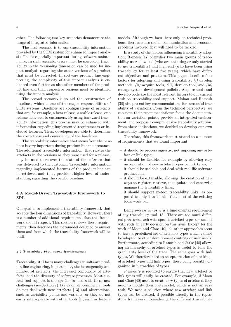
Figure 6 depicts the workflow of this framework. Theidea is to begin by creating an ATF repository, and pop-ulate it using either the appropriate Trace Register orthe core ExtractionManager. It is then possible to ex-ecute a Trace Query instance and pass the results tothe desired Trace View instance. The user can furtherrefine the query results by executing a new query, whichwill return a refined set of trace links or artefacts, untilthe desired information is reached. The idea is to per-form a round-trip between the queries and the views.The query results are passed to a view, which in turnallows the user to select a set of trace links or artefactsand execute a new query with that selection. The resultsmay also be exported to several formats, using specialviews for that purpose.
Fig. 6 ATF Framework Workflow
5.3 ATF Plugins
We have implemented a number of plugins that extendthe basic functionalities of the framework. These exper-iments confirmed some of our choices and demonstratedthe flexibility of the ATF. ATF plugins are standardEclipse plugins that may extend the ATF in three di-rections (see also Section 5.2): Trace Register, to pop-ulate a repository; Trace Query, to implement complexadvanced queries that should be of interest to end-users(e.g., impact analysis); Trace View, to visualize the re-sult of a query.
These plugins were developed independently, by dif-ferent members of the AMPLE project. Anyone can im-plement a plugin of interest to address his/her specific
traceability scenario and rely on the framework to pro-vide infrastructure and needed additional facilities.
5.3.1 Register Plugins. Register plugins introduces newartefacts and links in the repository. The artefact andlink types must have been created before inserting thedata. We implemented several of such plugins on differ-ent types of data:
– Populating from various kinds of development arte-facts. Plugin extractors were developed for importingartefacts or models produced by tools such as, Ratio-nal Rose, Enterprise Architect, MoPLine, or EclipseFeature Modelling Plugin (FMP). They are used toextract various kinds of artefacts such as use cases,actors, class diagrams, features models. These plug-ins would be mostly useful for Refinement or Simi-larity traceability links.
– Populating from source code. We have also imple-mented two independent Java extractors: one usingthe JavaCC parser, and the other using Eclipse JDT(Java Development Tools). Various levels of granu-larity of artefacts may be looked for in source code,such as packages, files, classes, methods or even state-ments. These plugins would be mostly useful for Re-finement or Similarity traceability links.
– Populating from MDE process. Members of the AM-PLE project defined two concurrent MDE tool chainsthat produce traceability data in XML format. Ex-tractors were defined that process these files to loadthe data in the repository. These plugins concentrateon Refinement or Similarity traceability links.
– Populating from source configuration system. We de-fined a plugin that interact with a Subversion serverto extract software configuration information. Thisplugin concentrates on Versioning traceability linksand will be described in detail in Section 5.4.
– Manually populating the repository. One plugin al-lows to manually define links between already regis-tered artefacts. This is intended to complement theother plugins by providing information that could notbe extracted automatically.
5.3.2 Query Plugins. Query plugins allow extractinginformation from the repository. It is intended to im-plement advanced queries that should be of interest toend-users. We have two such advanced queries:
– An impact analysis query that uses transitive closureon forward refinement traceability links to define allthe artefacts potentially impacted by a change in one(usually abstract) artefact.
– A feature interaction query that also uses transitiveclosure on forward refinement traceability links toidentify pairs of features that could present interac-tion issues. This happens when the intersection of thetransitive closure of the two features is not empty.

14 Nicolas Anquetil et al.
5.3.3 View Plugins. View plugins allow to visualize theresult of the queries. To visualize trace link graphs isvaluable, at least as an exploratory aid [25]. As in [33]we agree that visualizing traceability links is important,but getting a useful view is a non trivial task. This isparticularly the case for us since we use m-to-n links.For example, the realization traceability link may relateone software requirement to several design artefacts, allpackaged in one or two components.
Graph visualization is an old preoccupation of com-puter science. There are many tools available, for in-stance, graphviz [18], prefuse [23] and jung [53]. Onechallenge is visualizing a huge quantity of data. It re-quires specific tools such as those proposed in [41]. Tosolve the scalability issue, abstraction and clustering tech-niques (see [22]) are helpful. We explored different waysto visualize the trace links and will discuss this basicsupport here. We feel that more advanced support is theresponsibility of the information and visualization com-munity.
Because of the m-to-n links, trace information formsan hypergraph, a graph where links may relate morethan two vertices [8,21]. Although graphs have a verynatural and intuitive graphical representation (pointslinked by lines), hypergraphs may be more challenging.Unfortunately, there are few tools to represent and ma-nipulate hypergraphs.
We identified three possible representations for trace-ability links:
– represente hyper-edges as arrows with more than onesource or/and more than one target. This is the mostintuitive solution, but it is complex to render graph-ically, especially when there are many vertices scat-tered over the surface. We did not experiment thispossibility.
– use “sets” to represent the links, where one such setincludes all the vertices which are either source ortarget of an hyper-edge. This is similar to a Venn Di-agram [54]. It can look cluttered and directed edges(which traceability links are) are not easy to rep-resent. We experimented this solution but will notillustrate it here.
– promote the links to new kinds of vertices turningthe hypergraph into a bipartite graph: a graph withtwo different kinds of vertices, and vertices of onekind are only related to vertices of the other kind.It is visually less intuitive as one needs to identify“true” vertices, the artefacts, and “false” ones, thelinks. However, it suffers less from the problem ofscattered vertices than the first solution and can rep-resent directed edges. Another benefit is to be ableto use the numerous tools, measures and theory thatexist for bipartite graphs. Two examples of such rep-resentation are presented in figures 10 and 11.
We also experimented with non-graph representa-tion:
– Textual list of links, useful to export to a file or whenthere are many links.
– Textual hierarchical representation where the arte-facts and the links are unfolded on user demand (seeFigure 8, for an example). It does not allow a globalview of the links but provides a good and simple wayto explore and navigate the graph.
– Graphical hierarchical representation (see Figure 7),conceptually very similar to the previous one, butpossibly more intuitive to interpret.
5.3.4 Future Extensions. We are still working on ATFplugins to extend its capabilities. Two main explorationdirections are envisioned: advanced queries and visual-ization.
First we plan to implement more advanced queriesthat would solve concrete problems. Such problems mayinclude, for example: Test case coverage — to check thata feature is covered by at least one test case; Dead codeidentification — to check whether a given software com-ponent is actually related to some high level artefact(e.g., a SPL requirement, feature or variability); Correc-tion back-porting — to find all the versions of a changedartefact in all generated SPL applications; MDE debug-ging — to identify the source of an error in the genera-tion process.
Another exploration direction would be to try to im-prove the visualization of the links. One possibility weare interested in would be to take advantage of the or-thogonal traceability dimensions to show four views of agiven set of links according to the four dimensions. Twoproposals are envisioned: the first one would be similar towhat we currently have (graphical representations of thelinks) and one could turn on or off the drawing of par-ticular traceability dimensions to simplify the graph; thesecond one would offer four connected views where theartefacts would have the same position, but each viewwould present the links in one traceability dimension.
5.4 SCM Integration in ATF
One of the plugins implemented is dedicated to real-ize the integration of software configuration manage-ment with the traceability framework, so as to deal withthe forth traceability dimension (Versioning traceabil-ity). Although SCM and traceability are two relativelywell understood activities of software development, theirintegration is not completely trivial and need to be dis-cussed here.
The primary aspect of traceability that is enabled bySCM systems is the traceability of the evolution of ver-sioned items. Items inside the SCM system are subjectto evolution through revisions. To represent the evolu-tion of versioned items, the version set is often organizedin a version graph, whose nodes and edges correspond toversions and their relationships, respectively.

A Model-Driven Traceability Framework for Software Product Lines 15
Fig. 7 Screen Shot of the ATF Tree View
In general, there are two choices to represent in-tegrated information between an SCM system and atraceability system. Either the elements of the SCM sys-tem become first-class citizens in the traceability system,e.g., nodes in a traceability graph, or SCM informationis represented as metadata of specific traceability enti-ties, e.g., a property which states that a traced elementcorresponds to a certain file and revision in the SCMsystem.
The first approach can result in increased size for thedata in the traceability system, because not all changesin an artefact must have corresponding changes in thetraceability links. Thus, we have several traced elementswith the same traceability links. However, the approachalso provides a uniform way to query all dimensions oftraceability in one coherent framework.
The second approach can reduce the size of the trace-ability data, but it requires more elaborated synchro-nization and querying mechanisms. Synchronization isan issue if a sequence of versioned items has the sametraceability links, e.g., version 1 to 5 of an artefact. Inthis case, the integration must provide ways to representthis in the metadata. In addition, the query mechanismsmust be more elaborated to examine this metadata andcorrelate the trace links that are represented in the SCMsystem to the traceability information.
We have chosen the first approach and elected tomake SCM items first-class citizens of ATF. The infor-mation residing in the SCM system is made available toATF through extractors. Once the information is storedin ATF, traceability links can be established to specificversions of artefacts. An extractor for the Subversionsystem was implemented as a proof-of-concept [36].
Since ATF now includes different versions for arte-facts in the traceability graph, new trace links betweenartefacts must be specified by using the respective arte-fact versioning information. Without the version infor-
mation, the ATF cannot decide for which versions thelink is applicable and relies on a default policy that de-cides this applicability. Such a policy can be, for exam-ple, that the link is always provided for the latest versionof an item.
The integration of SCM information as first classcitizens offers many benefits. Firstly, the approach al-lows an easy correlation of the information from differ-ent SCM systems, by providing one integrated view ofthe information. Thus, the approach offers the possibil-ity to incorporate heterogeneous tools landscapes usedduring the software engineering process. Secondly, repos-itories can also come from different vendors and use dif-ferent versioning schemes. For example, Subversion usesa global versioning scheme, while CVS has independentversions for each item. Both systems can be representedusing an ATF integration. Finally, the approach allowsproviding versioning schemas for fine-grained traceabil-ity items that are usually not considered in SCM. Aspart of the AMPLE project, we have implemented afeature-driven versioning approach, that versions featuremodels in software product lines. The feature-driven ver-sioning allows to correlate versions of features with ver-sions of artefacts in SCM and with versions of products.Thus, enhanced traceability of variability in the productderivation is provided. This incorporates (i) traceabil-ity of variation points, i.e., features, into instantiationsof components and (ii) traceability of these instantiatedcomponents into the products.
6 ATF Instantiation
This section presents an instantiation example of theframework. The example is part of the reference instan-tiation that was created for the AMPLE project. It de-scribes end-to-end traceability from market requirements
16 Nicolas Anquetil et al.
to code, and includes product line features and UMLmodels.
ATF is a general purpose traceability framework andcan be configured to suit many different projects andtraceability scenarios. Thus, in the following, we describethe process of instantiating the ATF framework for aspecific software product line scenario.
The example comes from the Smart Home applica-tion domain, an “intelligent” home where doors, lights,entertainment, security, . . . are all controlled and inte-grated by computer. Our smart home example will userooms, two optional features (security and automaticwindow), lights and light controllers, and security de-vices, such as burglar alarms or presence detectors.
Initial requirements are grouped into common andvariable features, which determines the feature model.The requirements are documented by scenarios, whichare described with UML sequence diagrams, at designlevel, and further implemented in test cases. The featuremodel, with the help of scenarios, is designed into a UMLclass diagram which will be implemented by Java classes.For simplification purposes, as part of the MDE process,we suppose one builder “script” (or transformation) thatautomates the generation of applications.
6.1 Analyzing the Software Product Line Process
The first step to instantiate the framework is to definewhich artefacts are needed and how they relate to oneanother. In our example, we use a simplified process andwe assume the following steps: (i) Requirements Engi-neering, (ii) Variability Management, (iii) UML Design,and (iv) Implementation.
Another important issue is the granularity of thedata, or the degree of detail and precision in traced arte-facts. The extremes in the spectrum of granularity are alarge number of narrow categories, or a smaller numberof broad categories. The choice of granularity must begoverned by the kind of analysis to perform. For exam-ple, for a requirements coverage analysis one would needtraceability for individual requirements and the artefactsthat realize them. In this example, we use a multi-layeredgranularity approach. Mohan et al. advocate that sucha traceability plan is essential for effective change man-agement [39]. The artefacts include high level ones suchas an entire requirements document but also individualelements contained in such artefacts, such as individualrequirements.
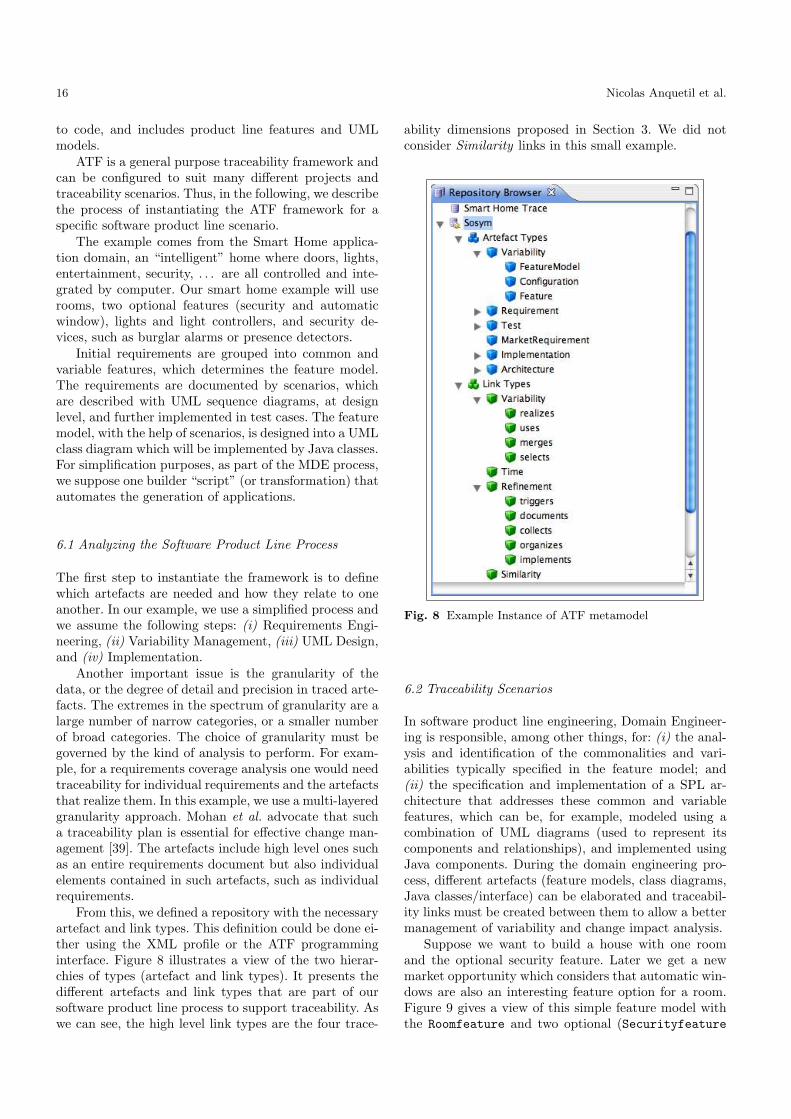
From this, we defined a repository with the necessaryartefact and link types. This definition could be done ei-ther using the XML profile or the ATF programminginterface. Figure 8 illustrates a view of the two hierar-chies of types (artefact and link types). It presents thedifferent artefacts and link types that are part of oursoftware product line process to support traceability. Aswe can see, the high level link types are the four trace-
ability dimensions proposed in Section 3. We did notconsider Similarity links in this small example.
Fig. 8 Example Instance of ATF metamodel
6.2 Traceability Scenarios
In software product line engineering, Domain Engineer-ing is responsible, among other things, for: (i) the anal-ysis and identification of the commonalities and vari-abilities typically specified in the feature model; and(ii) the specification and implementation of a SPL ar-chitecture that addresses these common and variablefeatures, which can be, for example, modeled using acombination of UML diagrams (used to represent itscomponents and relationships), and implemented usingJava components. During the domain engineering pro-cess, different artefacts (feature models, class diagrams,Java classes/interface) can be elaborated and traceabil-ity links must be created between them to allow a bettermanagement of variability and change impact analysis.
Suppose we want to build a house with one roomand the optional security feature. Later we get a newmarket opportunity which considers that automatic win-dows are also an interesting feature option for a room.Figure 9 gives a view of this simple feature model withthe Roomfeature and two optional (Securityfeature

A Model-Driven Traceability Framework for Software Product Lines 17
and Automaticwindowfeature) sub features. The de-sign was elaborated using the FMP plugin available athttp://gsd.uwaterloo.ca/projects/fmp-plugin/.
Fig. 9 Simple (FMP) Feature Model
First we need to perform domain engineering and tobuild two applications corresponding to a simple roomand a room with security. After application engineering,we get an initial trace set, which is depicted in Figure 10(top part). This view represents the artefacts createdand the Refinement links between them from domainand application engineering. Variability and Versioninglinks do not appear in the picture.
Figure 10 also shows a bipartite graph approach totraceability link visualization (see Section 5.3); the largenodes represent the artefacts and the small ones rep-resent the links. Links and artefacts are selectable inthis view and when one is selected, its properties (name,type, identifier) appear in the top part of the graph (greybackground). In top part of Figure 10, the feature modelartefact is selected (it is indicated by a bold arrow, atthe right hand side of the graph). When an artefact isselected (node 14 on the far right), the links stemmingfrom it are in light red, and the target artefacts of theselinks are pink colored (the eight nodes in darker grey).
The bottom part of the figure enlarges a part of thisgraph with the selected artefact (bottom right) a linkfrom it (called implements, a link type from the Refine-ment dimension), and several target artefacts (e.g., theUML class diagram and the UML light controller class).
The developers need to test this new application, sothey use the trace set repository to find the set of testcases applicable to the SmartHome product line. Thesteps to find these test cases could be:
1. Start from the product configuration (also called afeature model instance) that represents a specific SPLproduct/application derived from a selection of vari-able features in the SPL feature model;
2. Compute the requirements included in the productfrom this configuration and the realization links (Vari-ability dimension) in the product family;
3. Compute the transitive closure of Refinement links inthe domain engineering to find out all the test casesassociated to these requirements.
If the procedure needs to be repeated frequently, onecould imagine automating it with a new Trace Query
Fig. 10 View of the Initial Trace Set (top part) and enlargedview of some nodes (bottom part)
plugin. The following excerpt of Java code illustrateshow the query could be programmed:
Query<TraceLink> qLinks = qm.queryOnLinks();
qLinks.add(
Constraints.type(tm.findLinkTypeByName("uses")));
List<TraceLink> result = new List<TraceLink>();
for (List<TraceLink> lnk : qLinks.execute()) {
//test source name and target type
if (... && ...) {result.add(lnk);}
}
An empty query is first created from qm, a QueryManagerinstance (see Section 5.1). Then one adds the constraintsto this query; here we constrain on the type of link (usestype) that we want to use. Finally, a loop on the resultallows checking which of these links have the appropri-ate source or target. This is an example where the usesrelation is useful for efficiently access to the artefactsassociated to a product.
Let us assume that during the tests, the burglar on
test reveals that a requirement is missing: “light should
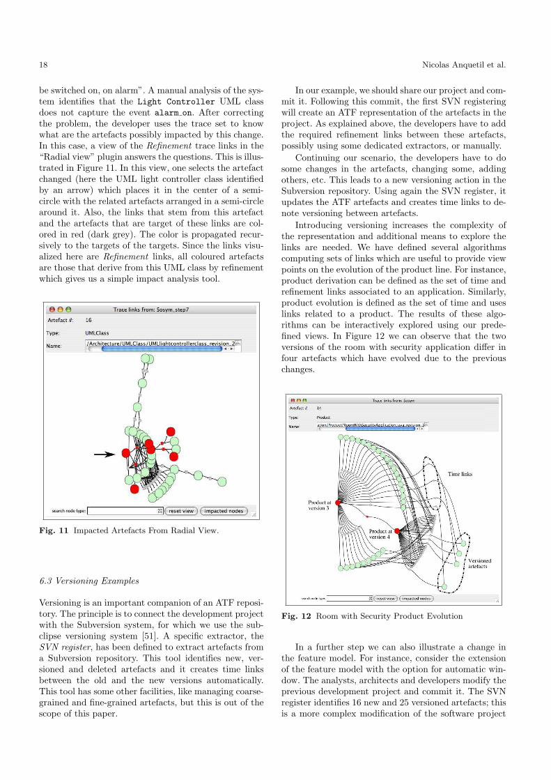
18 Nicolas Anquetil et al.
be switched on, on alarm”. A manual analysis of the sys-tem identifies that the Light Controller UML classdoes not capture the event alarm on. After correctingthe problem, the developer uses the trace set to knowwhat are the artefacts possibly impacted by this change.In this case, a view of the Refinement trace links in the“Radial view” plugin answers the questions. This is illus-trated in Figure 11. In this view, one selects the artefactchanged (here the UML light controller class identifiedby an arrow) which places it in the center of a semi-circle with the related artefacts arranged in a semi-circlearound it. Also, the links that stem from this artefactand the artefacts that are target of these links are col-ored in red (dark grey). The color is propagated recur-sively to the targets of the targets. Since the links visu-alized here are Refinement links, all coloured artefactsare those that derive from this UML class by refinementwhich gives us a simple impact analysis tool.
Fig. 11 Impacted Artefacts From Radial View.
6.3 Versioning Examples
Versioning is an important companion of an ATF reposi-tory. The principle is to connect the development projectwith the Subversion system, for which we use the sub-clipse versioning system [51]. A specific extractor, theSVN register, has been defined to extract artefacts froma Subversion repository. This tool identifies new, ver-sioned and deleted artefacts and it creates time linksbetween the old and the new versions automatically.This tool has some other facilities, like managing coarse-grained and fine-grained artefacts, but this is out of thescope of this paper.
In our example, we should share our project and com-mit it. Following this commit, the first SVN registeringwill create an ATF representation of the artefacts in theproject. As explained above, the developers have to addthe required refinement links between these artefacts,possibly using some dedicated extractors, or manually.
Continuing our scenario, the developers have to dosome changes in the artefacts, changing some, addingothers, etc. This leads to a new versioning action in theSubversion repository. Using again the SVN register, itupdates the ATF artefacts and creates time links to de-note versioning between artefacts.
Introducing versioning increases the complexity ofthe representation and additional means to explore thelinks are needed. We have defined several algorithmscomputing sets of links which are useful to provide viewpoints on the evolution of the product line. For instance,product derivation can be defined as the set of time andrefinement links associated to an application. Similarly,product evolution is defined as the set of time and useslinks related to a product. The results of these algo-rithms can be interactively explored using our prede-fined views. In Figure 12 we can observe that the twoversions of the room with security application differ infour artefacts which have evolved due to the previouschanges.
Fig. 12 Room with Security Product Evolution
In a further step we can also illustrate a change inthe feature model. For instance, consider the extensionof the feature model with the option for automatic win-dow. The analysts, architects and developers modify theprevious development project and commit it. The SVNregister identifies 16 new and 25 versioned artefacts; thisis a more complex modification of the software project

A Model-Driven Traceability Framework for Software Product Lines 19
than the previous change. At this step the feature modelevolution is significant, its realization in artefacts andtheir evolutions. Figure 13 represents an interactive viewof this graph complemented with some comments to helpthe reader. We can explore it to observe the structure ofthe feature model and the evolution of the realization ofthe features. For instance, the security feature has tworealizations, while the room feature has two different ver-sions.
Fig. 13 Feature Model Evolution
Other computations have been defined, like obtainingthe refinement set of a product or the comparisons oftwo set of links. Figure 14 depicts the comparison ofthe refinement sets of the first version of the room withsecurity application and the last version of the room withautomatic window and security features. Green nodes(or links) are common to both products while violet arespecific to the room with security, and yellow proper tothe product with automatic window.
This very simple example helps to understand howone could solve complex traceability problems using ourframework and based on the four orthogonal traceabilitydimensions we identified.
7 Related Work
We already reviewed related tools in Section 2 and closerelated work in Section 3.1. However some other specifictools have not yet been discussed.
Fig. 14 Two Products Comparison
7.1 Traceability Tools
Mohan and Ramesh [37] present a traceability and knowl-edge management framework that supports tracing com-monalities and variability in customer requirements totheir corresponding design artefacts. The framework pro-vides primitives to represent the conceptual elements,inputs and outputs of the system development process,as well as the links among them. The framework con-centrates mainly on the identification of common andvariable requirements, architectural design decisions andfunctional customizations done on the base product. Theconceptual model identifies the various actors, documentsand processes involved in the development process. Var-ious dimensions of traceability information are exposed:what information, who are the stakeholders, how the in-formation is represented and so on. These dimensions arevery different from what we identified and are not lim-ited to technical considerations. The traceability linksare typed by predefined kinds which is also different fromour flexible framework.
Jirapanthong and Zisman [26] give several reasons toexplain the difficulty of the traceability task in SPL (seeSection 3.1). They use an extension of the Feature-basedObject-oriented Method (FORM) [29]. Their approachrelies on six groups of relations subdivided into nine dif-ferent types of traceability relationship. The kernel ofthe system is a set of rules that are responsible for an-alyzing the documents and generate various traceabilityrelationships between them. The rule based tool sup-port seems a good way to automate the trace generation.In this approach, only classic object-oriented and UMLartefacts are considered. It manages different types ofartefacts and trace links but in an ad-hoc and unstruc-tured way. Also, the set of artefacts and link types is notadaptable to other needs. The approach was refined and
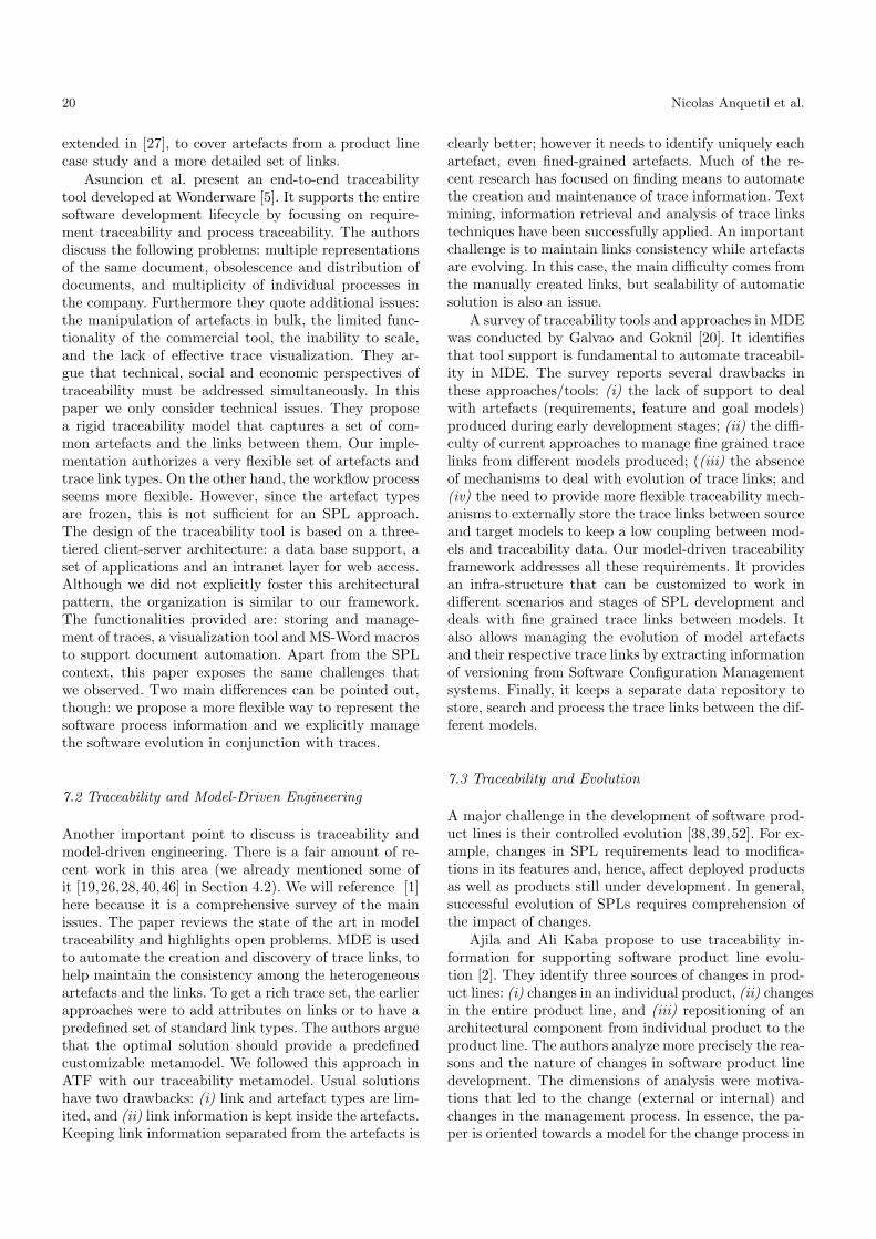
20 Nicolas Anquetil et al.
extended in [27], to cover artefacts from a product linecase study and a more detailed set of links.
Asuncion et al. present an end-to-end traceabilitytool developed at Wonderware [5]. It supports the entiresoftware development lifecycle by focusing on require-ment traceability and process traceability. The authorsdiscuss the following problems: multiple representationsof the same document, obsolescence and distribution ofdocuments, and multiplicity of individual processes inthe company. Furthermore they quote additional issues:the manipulation of artefacts in bulk, the limited func-tionality of the commercial tool, the inability to scale,and the lack of effective trace visualization. They ar-gue that technical, social and economic perspectives oftraceability must be addressed simultaneously. In thispaper we only consider technical issues. They proposea rigid traceability model that captures a set of com-mon artefacts and the links between them. Our imple-mentation authorizes a very flexible set of artefacts andtrace link types. On the other hand, the workflow processseems more flexible. However, since the artefact typesare frozen, this is not sufficient for an SPL approach.The design of the traceability tool is based on a three-tiered client-server architecture: a data base support, aset of applications and an intranet layer for web access.Although we did not explicitly foster this architecturalpattern, the organization is similar to our framework.The functionalities provided are: storing and manage-ment of traces, a visualization tool and MS-Word macrosto support document automation. Apart from the SPLcontext, this paper exposes the same challenges thatwe observed. Two main differences can be pointed out,though: we propose a more flexible way to represent thesoftware process information and we explicitly managethe software evolution in conjunction with traces.
7.2 Traceability and Model-Driven Engineering
Another important point to discuss is traceability andmodel-driven engineering. There is a fair amount of re-cent work in this area (we already mentioned some ofit [19,26,28,40,46] in Section 4.2). We will reference [1]here because it is a comprehensive survey of the mainissues. The paper reviews the state of the art in modeltraceability and highlights open problems. MDE is usedto automate the creation and discovery of trace links, tohelp maintain the consistency among the heterogeneousartefacts and the links. To get a rich trace set, the earlierapproaches were to add attributes on links or to have apredefined set of standard link types. The authors arguethat the optimal solution should provide a predefinedcustomizable metamodel. We followed this approach inATF with our traceability metamodel. Usual solutionshave two drawbacks: (i) link and artefact types are lim-ited, and (ii) link information is kept inside the artefacts.Keeping link information separated from the artefacts is
clearly better; however it needs to identify uniquely eachartefact, even fined-grained artefacts. Much of the re-cent research has focused on finding means to automatethe creation and maintenance of trace information. Textmining, information retrieval and analysis of trace linkstechniques have been successfully applied. An importantchallenge is to maintain links consistency while artefactsare evolving. In this case, the main difficulty comes fromthe manually created links, but scalability of automaticsolution is also an issue.
A survey of traceability tools and approaches in MDEwas conducted by Galvao and Goknil [20]. It identifiesthat tool support is fundamental to automate traceabil-ity in MDE. The survey reports several drawbacks inthese approaches/tools: (i) the lack of support to dealwith artefacts (requirements, feature and goal models)produced during early development stages; (ii) the diffi-culty of current approaches to manage fine grained tracelinks from different models produced; ((iii) the absenceof mechanisms to deal with evolution of trace links; and(iv) the need to provide more flexible traceability mech-anisms to externally store the trace links between sourceand target models to keep a low coupling between mod-els and traceability data. Our model-driven traceabilityframework addresses all these requirements. It providesan infra-structure that can be customized to work indifferent scenarios and stages of SPL development anddeals with fine grained trace links between models. Italso allows managing the evolution of model artefactsand their respective trace links by extracting informationof versioning from Software Configuration Managementsystems. Finally, it keeps a separate data repository tostore, search and process the trace links between the dif-ferent models.
7.3 Traceability and Evolution
A major challenge in the development of software prod-uct lines is their controlled evolution [38,39,52]. For ex-ample, changes in SPL requirements lead to modifica-tions in its features and, hence, affect deployed productsas well as products still under development. In general,successful evolution of SPLs requires comprehension ofthe impact of changes.
Ajila and Ali Kaba propose to use traceability in-formation for supporting software product line evolu-tion [2]. They identify three sources of changes in prod-uct lines: (i) changes in an individual product, (ii) changesin the entire product line, and (iii) repositioning of anarchitectural component from individual product to theproduct line. The authors analyze more precisely the rea-sons and the nature of changes in software product linedevelopment. The dimensions of analysis were motiva-tions that led to the change (external or internal) andchanges in the management process. In essence, the pa-per is oriented towards a model for the change process in

A Model-Driven Traceability Framework for Software Product Lines 21
SPL evolution. The authors propose to use impact anal-ysis on traces to determine a generalized change set forthe product line. This change set is to be monitored byinterested stakeholders to assess the risk of changes forthe software product line. However, the work does notdiscuss any means to handle traceability in SPL evolu-tion.
Krueger discusses the difficulty of managing the evo-lution of SPLs from the viewpoint of software configura-tion management (SCM) [31]. While this work makes noexplicit reference to traceability, the topic of SCM canbe viewed as a traceability work (as argued in Section3.2.2). From works such as [12] and [9], SCM systemscan be viewed as providing traceability between relatedcomponents in a product and traceability for their evo-lution in time, as well as traceability for the evolution ofthe products in time. Krueger identifies three new chal-lenges in SCM that arise from SPLE and outlines pos-sible solutions. The three challenges are phrased usingSCM terminology, but address the problem of tracing theevolution of software artefacts. Traceability of productline evolution is expressed as management of variationpoints, customizations and customization composition.
1. Variation point management is required for the vari-ations in the software artefacts, including differentways of instantiation. As a solution, variation pointsare implemented to include a collection of file vari-ants and logic to be able to identify such a file variantat any given point in the domain space.
2. Customization management deals with the composi-tions of common artefact, i.e., artefacts without vari-ations, and variant artefacts into customized com-ponents, by instantiating the variation points. Thisproblem is solved by assigning logical names to acomponent customization.
3. Customization composition management refers to thecomposition of common component and customizedcomponents into customized products. The proposedsolution associates a logical name to a customizedproduct with a list of customized components.
Kruger’s outlined solutions are influenced by the scopeand needs of configuration management and are there-fore limited to the abstraction of files and logical names,i.e., labelled configurations in SCM. None of the solu-tions is discussed with concrete implementations and ex-perience in actual usage.
7.4 Visualization of Trace Links
Visualization of traceability links is important and is nota simple task. In their work [33], Marcus et al. describeproperties related to trace links and argue that a trace-ability tool should be able to manipulate (add, delete,edit) these link properties. The authors further list 12
requirements for traceability visualization tool. We sup-port the majority of these requirements to varying de-grees.
Integration and interoperation with external softwaretools (concerning three out of the 12 requirements) iscurrently limited in our framework to data exchange.We export to XML, Excel format, and dot format (of theGraphViz tool [18]). An important feature of their tool(TraceViz) is the various textual and graphical views itoffers. Although we do have both textual and graphicalviews, their propositions could improve our basic views.On the other hand, our graphical view is interactive,allowing the user to move the artefacts around. Theirtool does not seem to have such facility.
8 Conclusion and Future Work
Software product lines are receiving increasing attentionin software industry over the last years. Traceability isalso one current important issue in software engineering,since it can bring several benefits to change impact anal-ysis during software evolution. As explained by severalauthors [13,38,39,48] traceability and software evolutionhave to be managed conjointly to increase the ability todevelop product families. Current industrial tools andeven academic approaches do not yet address end-to-end traceability for software product line engineering.The task is complex since one must consider severaldimensions: technical, social and economic. In our ap-proach, we mainly address the technical issues, postpon-ing the other questions to a later configuration and in-stallation stage of the tool support. However, the numberand heterogeneity of artefacts, the variety of trace linksand the numerous development approaches are effectiveproblems. Thus, we provide a generic and customizableframework that can be configured with artefact types,link types, and traceability functionalities relevant to aspecific context. This was done thanks to the use of acore traceability metamodel, which enables to define m-to-n trace links, scope and trace information. MDE pro-vides good support to define an extensible traceabilitymetamodel, and we implement it using the Ecore meta-model of EMF. Our work also identifies and strongly ar-gues for the use of four orthogonal dimensions to charac-terise trace links: refinement, similarity, variability andversioning. Refinement and similarity are typical dimen-sions adopted by current traceability tools. Variabilityand versioning were created to deal with the specificitiesof change management in the context of software prod-uct lines. We propose an integrated environment sup-porting both traceability and versioning. Furthermore,our framework takes into account the explicit variationdimension, and feature models play a central role in ver-sioning other artefacts.
The AMPLE Traceability Framework, developed toaddress different scenarios of SPL traceability, was de-

22 Nicolas Anquetil et al.
veloped on top of the Eclipse platform, as a set of ex-tensible plugins. The ATF architecture is based on themetamodel implementation and a data base repositoryto store trace information. This core part provides ba-sic functionalities to initialize the framework and to per-sist/access the trace data. Moreover, the graphical front-end defines extension points and facilities for trace reg-istering, querying and viewing. It allows building trace-ability scenarios that connect groups of trace registers,queries and views dedicated to a specific analysis task. Aworkflow established for the ATF front-end guaranteesthat the various plugins (extractors, registers, queriesand views) can work together adequately and in theway defined by the framework users to select and re-fine its trace link sets. Different trace extractors, regis-ter, queries and views can be defined, as Eclipse plugins,to extend the base traceability functionality provided byATF.
Our framework defines some core functions, but moreis needed to get an effective tool support for a real devel-opment environment. We expect to improve our views,specifically to get orthogonal and synchronized views ofthe trace repository. This would help the navigation aswell as understanding the interactions between the fourdimensions of a SPL development. As suggested by pre-vious work [13,38,39,48], to get a better traceability so-lution, we should investigate the development processand the trace strategy. In the AMPLE project we areworking on a smart home case study, using a complexSPL process mixing model-driven and aspect-orientedengineering techniques. We intend to validate the ATFframework to guarantee that it can deal with differentand complex SPL traceability scenarios. Different SPLadoption strategies are being explored, varying from: (i)a proactive development — that model and specify thedevelopment artefacts as a series of model transforma-tions to produce the SPL; and (ii) a extractive/reactivedevelopment — that seeks to derive the SPL from ex-isting products. Each of these scenarios demand spe-cific traceability tools in the presence of changes to theSPL artifacts and products. We are mainly concentratedon providing support: (i) to trace variations across do-main engineering and application engineering; and (ii)to provide feedback to architects, designers and devel-opers about the current state or the design decision ofthe product lines. This last issue is one point identifiedin [13,38], which has the benefit of communication andcooperation in the development team. A rational designdecision analyzer is being designed and implemented ontop of the ATF front-end module. Additionally, our in-dustrial experience in AMPLE is allowing us to explorethe automatic extraction and maintenance of trace linksfrom existing transformations between models producedin the SPL engineering.
The taxonomy of trace links has been investigated inseveral papers [2,26,48,56]. However, as we previouslysaid, these are mostly ad-hoc and non structured rela-
tionships. The seminal paper of Ramesh and Jarke [48]discussed such a taxonomy but in the context of require-ment traceability. The four dimensions identified in thispaper (Section 3) are a first attempt to understand andorganize their dependencies, and a finer analysis was pro-posed in [30]. More work is needed here to build a stan-dard set of relationships, with a clear hierarchy and witha well accepted semantics.
Acknowledgments
The authors wish to thank Vasco Amaral and Joao Araujofrom Universidade Nova de Lisboa for their help in proofreading this article and for their suggestions to improveits writing.
This work is funded by the European FP7 STREPproject AMPLE.
References
1. Neta Aizenbud-Reshef, Brian T. Nolan, Julia Rubin, andYael Shaham-Gafni. Model traceability. IBM SystemsJournal, 45(3):515–526, July 2006.
2. Samuel Ajila and Badara Ali Kaba. Using TraceabilityMechanisms to Support Software Product Line Evolu-tion. In Du Zhang, Eric Gregoire, and Doug DeGroot,editors, Proceedings of the 2004 IEEE International Con-ference on Information Reuse and Integration, IRI, pages157–162. IEEE Systems, Man, and Cybernetics Society,2004.
3. Joao Paulo Almeida, Pascal van Eck, and Maria-EugeniaIacob. Requirements traceability and transformationconformance in model-driven development. In Proceed-ings of the 10th International Enterprise DistributedObject Computing Conference (EDOC), pages 355–366,Washington, DC, USA, 2006.
4. Bastien Amar, Herve Leblanc, and Bernard Coulette. Atraceability engine dedicated to model transformation forsoftware engineering. In Jon Oldevik, Gøran K. Olsen,Tor Neple, and Richard Paige, editors, ECMDA Trace-ability Workshop (ECMDA-TW) 2008 Proceedings, 2008.
5. Hazeline U. Asuncion, Frederic Francois, and Richard N.Taylor. An end-to-end industrial software traceabilitytool. In ESEC-FSE ’07: Proceedings of the the 6th jointmeeting of the European software engineering conferenceand the ACM SIGSOFT symposium on The foundationsof software engineering, pages 115–124, New York, NY,USA, 2007. ACM.
6. Joachim Bayer and Tanya Widen. Introducing trace-ability to product lines. In Frank van der Linden, edi-tor, Proc. of the 4th Int. Workshop on Software Product-Family Engineering (PFE), volume 2290 of Lecture Notesin Computer Science, pages 409–416, Bilbao (Spain), Oc-tober 2001.
7. Kathrin Berg, Judith Bishop, and Dirk Muthig. Trac-ing software product line variability: from problem tosolution space. In SAICSIT’05: Proceedings of the 2005annual research conference of the South African instituteof computer scientists and information technologists on
A Model-Driven Traceability Framework for Software Product Lines 23
IT research in developing countries, pages 182–191, Re-public of South Africa, 2005. South African Institute forComputer Scientists and Information Technologists.
8. Claude Berge. Graphes et hypergraphes. Dunod, 1970.9. Jane Cleland-Huang, Carl K. Chang, and Mark Chris-
tensen. Event-based traceability for managing evolution-ary change. IEEE Transactions on Software Engineering,29(9):796–810, September 2003.
10. Jane Cleland-Huang, Carl K. Chang, Gaurav Sethi, Ku-mar Javvaji, Haijian Hu, and Jinchun Xia. Automat-ing speculative queries through event-based requirementstraceability. In Proc. of the 10th Int. Conference onRequirements Engineering (RE), pages 289–298, Essen(Germany), September 2002.
11. Ben Collins-Sussman, Brian W. Fitzpatrick, andC. Michael Pilato. Version Control with Subversion.O’Reilly & Associates, Inc., 2006. For version 1.6.
12. Susan Dart. Concepts in configuration management sys-tems. In Proceedings of the 3rd international workshopon Software configuration management, pages 1–18, NewYork, NY, USA, 1991. ACM Press.
13. Ralf Domges and Klaus Pohl. Adapting traceability en-vironments to project-specific needs. Commun. ACM,41(12):54–62, 1998.
14. http://www.eclipse.org/. Last accessed: 05/04/2009.15. Ecore: Eclipse modeling framework project: Meta model.
http://www.eclipse.org/modeling/emf/?project=emf.Last accessed: 04/20/2009.
16. Alexander Egyed. A scenario-driven approach to tracedependency analysis. IEEE Transactions on SoftwareEngineering, 29(2):116–132, February 2003.
17. Alexander Egyed and Paul Grunbacher. Automatingrequirements traceability: Beyond the record & replayparadigm. In ASE, pages 163–171. IEEE Computer So-ciety, 2002.
18. John Ellson, Emden Gansner, Lefteris Koutsofios,Stephen C. North, and Gordon Woodhull. Graphviz —open source graph drawing tools. Lecture Notes in Com-puter Science, 2265:483–484, 2002.
19. Jean-Remi Falleri, Marianne Huchard, and Claire Nebut.Towards a traceability framework for model transforma-tions in kermeta. In J. Aagedal, T. Neple, and J. Oldevik,editors, ECMDA Traceability Workshop (ECMDA-TW)2006 Proceedings, pages 31–40, 2006.
20. Ismenia Galvao and Arda Goknil. Survey of traceabil-ity approaches in model-driven engineering. In EDOC’07: Proceedings of the 11th IEEE International En-terprise Distributed Object Computing Conference, page313, Washington, DC, USA, 2007. IEEE Computer So-ciety.
21. Frank Harary. Graph theory. Addison-Wesley, 1969.22. John A. Hartigan. Clustering Algorithms. John Wiley &
Sons, Inc., New York, NY, USA, 1975.23. Jeffrey Heer. The prefuse visualization toolkit.
http://prefuse.org/.24. Theresa Hunt. Vertical and horizontal requirements re-
lationships. Last accessed: 04/22/2009, 2007.25. Jean-Daniel Fekete and Jarke J. van Wijk and John
T Stasko and Chris North. Information Visualization:Human-Centered Issues and Perspectives, volume 4950 ofLecture Notes in Computer Science, chapter The Valueof Information Visualization, pages 1–18. Springer, 2008.
26. Waraporn Jirapanthong and Andrea Zisman. Supportingproduct line development through traceability. In Proc.of the 12th Asia-Pacific Software Engineering Confer-ence (APSEC), pages 506–514, Taipei (Taiwan), 2005.
27. Waraporn Jirapanthong and Andrea Zisman. Xtraque:traceability for product line systems. Journal of Softwareand Systems Modeling (SOSYM), 8(1):117–144, 2007.
28. Frederic Jouault. Loosely coupled traceability for ATL.In Jon Oldevik and Jan Aagedal, editors, ECMDATraceability Workshop (ECMDA-TW) 2005 Proceedings,pages 29–37, 2005.
29. Kyo C. Kang, Sajoong Kim, Jaejoon Lee, Kijoo Kim,Euiseob Shin, and Moonhang Huh. FORM: A feature-oriented reuse method with domain-specific reference ar-chitectures. Annals of Software Engineering, 5:143–168,1998.
30. Safoora Shakil Khan, Phil Greenwood, Alessandro Gar-cia, and Awais Rashid. On the interplay of requirementsdependencies and architecture evolution: An exploratorystudy. In Proceedings of the 20th International Con-ference on Advanced Information Systems Engineering,CAiSE 2008. Springer Verlag, jun. 16-20 2008. (to ap-pear).
31. Charles W. Krueger. Variation management for softwareproduction lines. In SPLC 2: Proceedings of the Sec-ond International Conference on Software Product Lines,pages 37–48, London, UK, 2002. Springer-Verlag.
32. Angelina E. Limon and Juan Garbajosa. The need fora unifying traceability scheme. In Jon Oldevik andJan Aagedal, editors, ECMDA Traceability Workshop(ECMDA-TW) 2005 Proceedings, pages 47–56, 2005.
33. Andrian Marcus, Xinrong Xie, and Denys Poshyvanyk.When and how to visualize traceability links? In TEFSE’05: Proceedings of the 3rd international workshop onTraceability in emerging forms of software engineering,pages 56–61, New York, NY, USA, 2005. ACM.
34. David Megginson. Xml performance and size. Last ac-cessed: 04/23/2009, May 2005.
35. Microsoft. Visual source-safe. http://msdn.microsoft.com/en-us/vstudio/aa700907.aspx. Last accessed: 04/23/2009.
36. Ralf Mitschke and Michael Eichberg. Supporting theEvolution of Software Product Lines. In Jon Olde-vik, Gøran K. Olsen, Tor Neple, and Richard Paige,editors, ECMDA Traceability Workshop (ECMDA-TW)2008 Proceedings, pages 87–96, 2008.
37. Kannan Mohan and Balasubramaniam Ramesh. Man-aging variability with traceability in product and servicefamilies. In Proceedings of the 35th Hawaii InternationalConference on System Sciences, pages 1309–1317, 2002.
38. Kannan Mohan and Balasubramaniam Ramesh. Tracingvariations in software product families. Communicationsof ACM, 50(12):68–73, 2007.
39. Kannan Mohan, Peng Xu, and BalasubramaniamRamesh. Improving the change-management process.Commun. ACM, 51(5):59–64, 2008.
40. Mikyeong Moon and Heung S. Chae. A metamodel ap-proach to architecture variability in a product line. InSpringer-Verlag, editor, Proceedings of the Reuse of Off-the-Shelf Components, 9th International Conference onSoftware Reuse, volume 4039 of LNCS, pages 115–126,2006.

24 Nicolas Anquetil et al.
41. Niklas Elmqvist and Thanh-Nghi Do and Howard Good-ell and Nathalie Henry and Jean-Daniel Fekete. ZAME:Interactive Large-Scale Graph Visualization. In Proceed-ings of the IEEE Pacific Visualization Symposium 2008,pages 215–222. IEEE Press, March 2008.
42. OMG. Meta object facility, mof 2.0.http://www.omg.org/spec/mof/2.0/, OMG, 2006.
43. Richard F. Paige, Gøran K. Olsen, Dimitrios S. Kolovos,Steffen Zschaler, and Christopher Power. Build-ing model-driven engineering traceability classifications.In Jon Oldevik, Gøran K. Olsen, Tor Neple, andRichard Paige, editors, ECMDA Traceability Workshop(ECMDA-TW) 2008 Proceedings, pages 49–58, 2008.
44. Shari L. Pfleeger and Shawn A. Bohner. A framework forsoftware maintenance metrics. In Proceedings of the Con-ference on Software Maintenance, pages 320–327, 1990.
45. Klaus Pohl, Gunter Bockle, and Frank van der Lin-den. Software Product Line Engineering - Foundations,Principles, and Techniques. Springer Verlag, Heidelberg,2005.
46. ModelWare Project. Traceability metamodel and sys-tem solution. http://www.modelware-ist.org, Model-Ware Project, Deliverable D1.6, 2006.
47. Balasubramaniam Ramesh. Factors influencing require-ments traceability practice. Communications of theACM, 41(12):37–44, 1998.
48. Balasubramaniam Ramesh and Matthias Jarke. To-ward Reference Models for Requirements Traceability.IEEE Transactions on Software Engineering, 27(1):58–93, 2001.
49. Matthias Riebisch. Supporting evolutionary develop-ment by feature models and traceability links. In Proc.of the 11th International Conference on Engineering ofComputer-Based Systems (ECBS), pages 370–377, Brno(Czech Republic), May 2004.
50. Andre Sousa, Uira Kulesza, Andreas Rummler, NicolasAnquetil, Ralf Mitschke, Ana Moreira, Vasco Amaral,and Joao Araujo. A Model-Driven Traceability Frame-work to Software Product Line Development. In JonOldevik, Gøran K. Olsen, Tor Neple, and Richard Paige,editors, ECMDA Traceability Workshop (ECMDA-TW)2008 Proceedings, pages 97–109, 2008.
51. http://subclipse.tigris.org/. Last consulted on:05/0/2009.
52. Mikael Svahnberg and Jan Bosch. Evolution in softwareproduct lines: Two cases. Journal of Software Mainte-nance, 11(6):391–422, November 1999.
53. JUNG Framework Development Team. Java universalnetwork/graph framework. http://jung.sourceforge.net/,2008.
54. John Venn. On the Diagrammatic and MechanicalRepresentation of Propositions and Reasonings. DublinPhilosophical Magazine and Journal of Science, 9(59):1–18, July 1880.
55. Stale Walderhaug, Ulrik Johansen, Erlend Stav, andJan Aagedal. Towards a generic solution for traceabil-ity in mdd. In J. Aagedal, T. Neple, and J. Oldevik,editors, ECMDA Traceability Workshop (ECMDA-TW)2006 Proceedings, 2006.
56. Roel Wieringa. Traceability and modularity in softwaredesign. In Proceedings of the 9th International Workshopon Software Specification and Design, pages 87–95, 1998.