a miniature ultransonic pump using a bending disk transducer and a gap
TRANSCRIPT
www.elsevier.com/locate/ultras
Ultrasonics 44 (2006) e575–e579
A miniature ultransonic pump using a bending disktransducer and a gap
Takeshi Hasegawa *, Kentaro Nakamura, Sadayuki Ueha
Precision and Intelligence Laboratory, Tokyo Institute of Technology, Japan
Available online 5 June 2006
Abstract
It is known that if a pipe end is faced at a vibrating surface in liquid with a small gap, liquid is suctioned into the pipe. As a miniatureconfiguration, we introduce a bending disk transducer 30 mm in diameter using a ring-shaped PZT element. The disk vibrator is workedat the fundamental resonance frequency of 19 kHz of the bending mode. To optimize the pipe geometry, we experimentally investigatedthe effect of the outer diameter on the pump performance. As a result, the outer/inner diameter ratio of 3:2 is optimum for the gap smal-ler than 20 lm. We achieved the maximum pump pressure of 14.8 kPa and the maximum flow rate of 10 ml/min. using the prototypepump.� 2006 Elsevier B.V. All rights reserved.
1. Introduction
In recent years, small fluidic pumps have been in greatdemand for devices such as droplet dispensing machines,medical apparatus, fuel supply pumps for miniature fuelcells, and water-cooled central processing units for per-sonal computers.
The conventional electromagnetic pump has difficultieswith miniaturization and the radiation of electromagneticnoise. Several miniature pumps using piezoelectrically [1]or electrostatically [2] excited membrane vibration havebeen proposed. Most of these pumps require valves to con-trol the direction of flow. However, the valves have prob-lems of wear and clogging due to bubbles and particles.The vibration frequency is low in the usual design, withinthe audible range, and noise and vibration cause difficultiesin practical installation. On the other hand, the valve canbe eliminated if the acoustic effect of high-frequency ultra-sound acting directly on a fluid, such as the radiation forceand acoustic streaming, is used [3,4]. However, the pump
0041-624X/$ - see front matter � 2006 Elsevier B.V. All rights reserved.
doi:10.1016/j.ultras.2006.05.061
* Corresponding author.E-mail address: [email protected] (T. Hasegawa).
performance is low compared with that of pumps withvalves.
The authors have been investigating the phenomenon ofan ultrasonically vibrating surface and a pipe with a smallgap into fluid [5,6]. If a pipe end is faced at a piston-vibrat-ing surface in liquid with a small gap, liquid is sucked intothe pipe. The present ultrasonic pump is based on this phe-nomenon to induce flow.
In this paper, we introduce a miniature configurationwith a 30 mm diameter bending disk transducer. To deter-mine the pipe geometry, first, we experimentally investigatethe effect of the outer diameter. For simplicity, we use alongitudinal bolt-clamped Langevin transducer (BLT) forthe experiments. The experiments show that the pipeouter/inner diameter ratio of 3:2 is optimum in the smallergap region. Next, using the optimum pipe with outer diam-eter of 5 mm and inner diameter of 3.5 mm, we fabricated aminiature pump. The maximum pump pressure of 14.8 kPaand the maximum flow rate of 10 ml/min. were achievedwhen the gap was 20 lm.
2. Configurations of the miniature ultrasonic pump
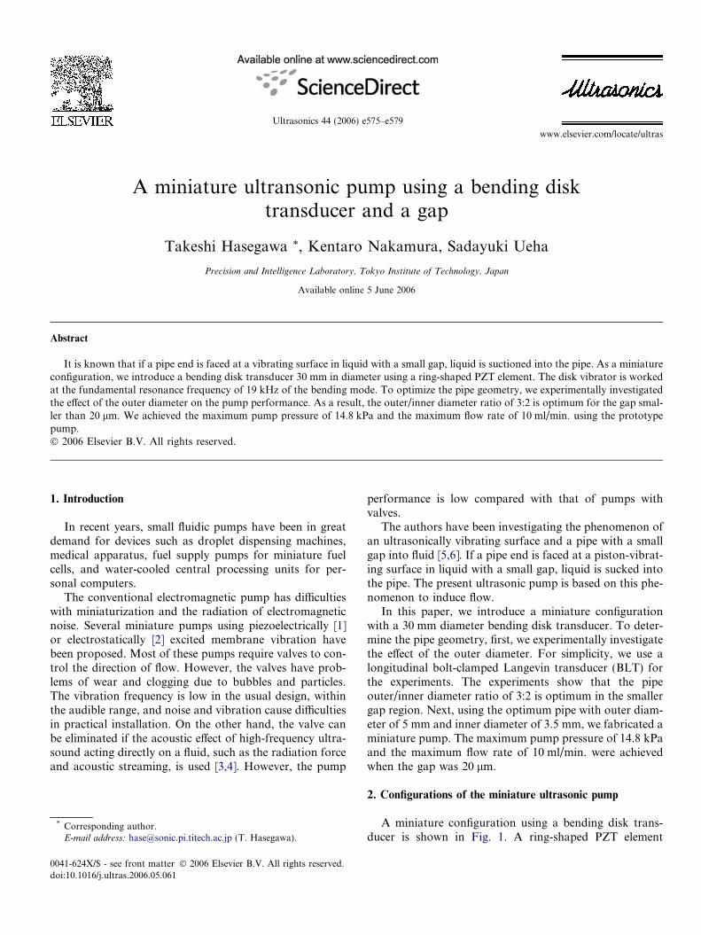
A miniature configuration using a bending disk trans-ducer is shown in Fig. 1. A ring-shaped PZT element
Frame
O-ringAluminium disk
PZT element O-ringFrame
40 mm
Gap
Nut
(a) (b)
Screw
Pipe
Water height (h)
LDV
10 mm
Vibration distribution
Fig. 1. Miniature pump using a bending disk: (a) structure; (b) crosssection.
e576 T. Hasegawa et al. / Ultrasonics 44 (2006) e575–e579
(30 mm in outer diameter, 15 mm in inner diameter and2 mm in thickness) is bonded on the back of the aluminumdisk 30 mm in diameter and 0.8 mm in thickness. The diskvibrator is softly supported by frames and O-rings at its cir-cumference, and is worked at the resonance frequency of19 kHz of the first bending mode. A pipe is installed per-pendicularly to the center of the disk vibrator with a smallgap. The distance from the vibrating surface to the watersurface in the water tank is 2 mm. The pump performanceis evaluated by the maximum pump pressure P defined asP = qgh with water density q, gravitational acceleration g
and water height in the pipe h.
3. Optimization of the pump geometry
3.1. Experimental setup
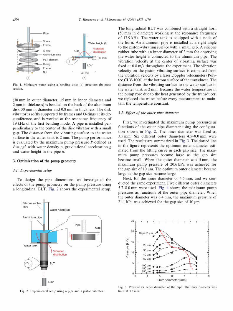
To design the pipe dimensions, we investigated theeffects of the pump geometry on the pump pressure usinga longitudinal BLT. Fig. 2 shows the experimental setup.
Water tank
Water height (h)
Vibration distribution
Aluminium pipe
BLT
Silicone rubbertube
GapPipe
LDV
Fig. 2. Experimental setup using a pipe and a piston vibrator.
The longitudinal BLT was combined with a straight horn(50 mm in diameter) working at the resonance frequencyof 17.9 kHz. The water tank is equipped with a node ofthe horn. An aluminum pipe is installed at a right angleto the piston-vibrating surface with a small gap. A siliconerubber tube with an inner diameter of 3 mm for observingthe water height is connected to the aluminum pipe. Thevibration velocity at the center of vibrating surface wasfixed at 0.8 m/s throughout the experiment. The vibrationvelocity on the piston-vibrating surface is estimated fromthe vibration velocity by a laser Doppler velocimeter (Poly-tec CLV-1000) at the bottom surface of the transducer. Thedistance from the vibrating surface to the water surface inthe water tank is 2 mm. Because the water temperature inthe pump rose due to the heat generated by the transducer,we replaced the water before every measurement to main-tain the temperature constant.
3.2. Effect of the outer pipe diameter
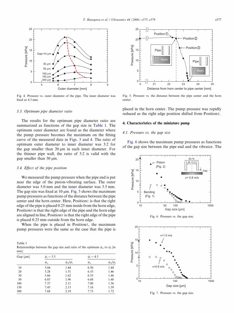
First, we investigated the maximum pump pressures asfunctions of the outer pipe diameter using the configura-tion shown in Fig. 2. The inner diameter was fixed at3.5 mm. Six different outer diameters 4.5–8.0 mm wereused. The results are summarized in Fig. 3. The dotted linein the figure represents the optimum outer diameter esti-mated from the fitting curve in each gap size. The maxi-mum pump pressures became large as the gap sizebecame small. When the outer diameter was 5 mm, themaximum pump pressure of 20.6 kPa was achieved forthe gap size of 10 lm. The optimum outer diameter becamelarge as the gap size became large.
Next, for the inner diameter of 4.5 mm, and we con-ducted the same experiment. Five different outer diameters5.7–8.0 mm were used. Fig. 4 shows the maximum pumppressures as functions of the outer pipe diameter. Whenthe outer diameter was 6.4 mm, the maximum pressure of21.1 kPa was achieved for the gap size of 10 lm.
3 4 5 6 7 8 90
5
10
15
20
25
Outer diameter [mm]
Pres
sure
[kPa
]
Gap=10 μm
50 μm
100 μm150 μm250 μm
20 μm
30 μm40 μm
Fig. 3. Pressure vs. outer diameter of the pipe. The inner diameter wasfixed at 3.5 mm.
Gap=10 μm
100 μm150 μm300 μm
30 μm
50 μm
5 6 7 8 90
5
10
15
20
25
Outer diameter [mm]
Pres
sure
[kPa
]
Fig. 4. Pressure vs. outer diameter of the pipe. The inner diameter wasfixed at 4.5 mm.
0
Position 2
Position 3
Position 1
21 22 23 24 250
5
10
15
20
25
Distance from horn center to pipe center [mm]
Pres
sure
[kPa
]
Pipe
Horn Pipe
Horn
Fig. 5. Pressure vs. the distance between the pipe center and the horncenter.
0
5
10
15
20
Pres
sure
[kPa
]
Piston
Bending
Gap size [µm]10 100 1000
v= 0.8 m/s
50
Gap
Øo=5Øi =3.5
(Fig. 2)
(Fig. 1)
Fig. 6. Pressure vs. the gap size.
20
T. Hasegawa et al. / Ultrasonics 44 (2006) e575–e579 e577
3.3. Optimum pipe diameter ratio
The results for the optimum pipe diameter ratio aresummarized as functions of the gap size in Table 1. Theoptimum outer diameter are found as the diameter wherethe pump pressure becomes the maximum on the fittingcurve of the measured date in Figs. 3 and 4. The ratio ofoptimum outer diameter to inner diameter was 3:2 forthe gap smaller than 20 lm in each inner diameter. Forthe thinner pipe wall, the ratio of 3:2 is valid with thegap smaller than 50 lm.
3.4. Effect of the pipe position
We measured the pump pressure when the pipe end is putnear the edge of the piston-vibrating surface. The outerdiameter was 5.0 mm and the inner diameter was 3.5 mm.The gap size was fixed at 10 lm. Fig. 5 shows the maximumpump pressures as functions of the distance between the pipecenter and the horn center. Here, Position is that the rightedge of the pipe is placed 0.25 mm inside from the horn edge,Position is that the right edge of the pipe and the horn edgeare aligned in line, Position is that the right edge of the pipeis placed 0.25 mm outside from the horn edge.
When the pipe is placed in Position , the maximumpump pressures were the same as the case that the pipe is
Table 1Relationships between the gap size and ratio of the optimum /o to /i [inmm]
Gap [lm] /i = 3.5 /i = 4.5
/o /o//i /o /o//i
10 5.04 1.44 6.50 1.4420 5.28 1.51 6.55 1.4630 5.66 1.62 6.55 1.4650 6.85 1.96 6.68 1.48
100 7.37 2.11 7.00 1.56150 7.45 2.13 7.16 1.59300 7.68 2.19 7.73 1.72
placed in the horn center. The pump pressure was rapidlyreduced as the right edge position shifted from Position .
4. Characteristics of the miniature pump
4.1. Pressure vs. the gap size
Fig. 6 shows the maximum pump pressures as functionsof the gap size between the pipe end and the vibrator. The
10 100
Gap size [µm]1000
0
5
10
15
Pres
sure
[kPa
]
v=0.8 m/s
v=1.0 m/s
Fig. 7. Pressure vs. the gap size.
0 5 10 15 20 25 300
0.2
0.4
0.6
0.8
1.0
Radial position [mm]
Vibr
atio
n ve
loci
ty [a
rb.]
0 5 10 15 20 25 300
0.2
0.4
0.6
0.8
1.0
Radial position [mm]
Vibr
atio
n ve
loci
ty [a
rb.]
0 5 10 15 20 25 300
0.2
0.4
0.6
0.8
1.0
Radial position [mm]Vi
brat
ion
velo
city
[arb
.]
PipeDisk PZT
2.5 mm 5 mmPosition 2 Position 3Position 1
Fig. 8. The positions of the pipe.
e578 T. Hasegawa et al. / Ultrasonics 44 (2006) e575–e579
vibration velocity at the piston-vibrated surface/disk centerwas fixed at 0.8 m/s. The outer diameter was 5.0 mm andthe inner diameter was 3.5 mm, because the pressurereached the maximum when the outer diameter was5 mm, as shown in the previous section. When the gap sizewas larger than 50 lm, the bending type showed the similarcharacteristics as the piston type. However, if the gapbecame smaller than 50 lm, the piston showed betterresults than bending.
Using the configuration shown in Fig. 1, for two differ-ent center vibration velocities at 0.8, 1.0 m/s, the maximumpump pressures were measured as functions of the gap sizebetween the pipe end and the vibrator. The results areshown in Fig. 7. We achieved the maximum pump pressureof 14.8 kPa when the gap size was 20 lm and vibrationvelocity was 1.0 m/s.
4.2. Effect of the vibration distribution gradient
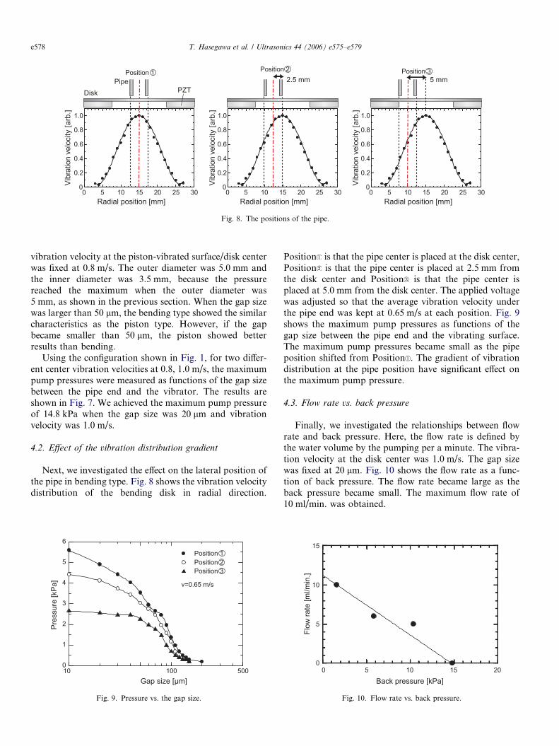
Next, we investigated the effect on the lateral position ofthe pipe in bending type. Fig. 8 shows the vibration velocitydistribution of the bending disk in radial direction.
10 1000
1
2
3
4
5
6
Gap size [µm]
Pres
sure
[kPa
]
500
v=0.65 m/s
Position 3Position 2Position 1
Fig. 9. Pressure vs. the gap size.
Position is that the pipe center is placed at the disk center,Position is that the pipe center is placed at 2.5 mm fromthe disk center and Position is that the pipe center isplaced at 5.0 mm from the disk center. The applied voltagewas adjusted so that the average vibration velocity underthe pipe end was kept at 0.65 m/s at each position. Fig. 9shows the maximum pump pressures as functions of thegap size between the pipe end and the vibrating surface.The maximum pump pressures became small as the pipeposition shifted from Position . The gradient of vibrationdistribution at the pipe position have significant effect onthe maximum pump pressure.
4.3. Flow rate vs. back pressure
Finally, we investigated the relationships between flowrate and back pressure. Here, the flow rate is defined bythe water volume by the pumping per a minute. The vibra-tion velocity at the disk center was 1.0 m/s. The gap sizewas fixed at 20 lm. Fig. 10 shows the flow rate as a func-tion of back pressure. The flow rate became large as theback pressure became small. The maximum flow rate of10 ml/min. was obtained.
05 10 15 20
5
10
15
Back pressure [kPa]
Flow
rate
[ml/m
in.]
0
Fig. 10. Flow rate vs. back pressure.
T. Hasegawa et al. / Ultrasonics 44 (2006) e575–e579 e579
5. Conclusions
We introduced a miniature configuration for ultrasonicpump. The pump consists of a bending disk transducerwith a small gap. In the experiments, we observed a signif-icant effect of the outer diameter of pipe on the pump per-formance. Optimum ratio of outer diameter to innerdiameter was found to be 3:2 for small gap region. Ratioof 3:2 is valid for wider gap region when the pipe wallthickness is thinner. Next, we achieved a maximum pumppressure of 14.8 kPa and a maximum flow rate of 10 ml/min. when the gap size was 20 lm for a pipe with outerand inner diameters of 5 mm and 3.5 mm, respectively.
The gradient of vibration distribution under pipe end haveremarkable effect on pump pressure.
References
[1] I. Ederer, P. Raetsch, W. Schullerus, C. Tille, U. Zech, Sens. Actuat. 62(1997) 752.
[2] O. Francais, I. Dufour, Sens. Actuat. 70 (1998) 56.[3] N.-T. Nguyen, R.M. White, IEEE Trans. Ultrason. Ferroelectr. Freq.
Control 47 (2000) 1463.[4] K. Chono, N. Shimizu, Y. Matsui, J. Kondoh, S. Shiokawa, Jpn. J.
Appl. Phys. 43 (2004) 2987.[5] C.-H. Yun, T. Hasegawa, K. Nakamura, S. Ueha, Jpn. J. Appl. Phys.
43 (2004) 2864.[6] T. Hasegawa, K. Nakamura, S. Ueha, Jpn. J. Appl. Phys. 44 (2005) 4658.