a methodology for parametric production planning in preliminary aircraft design.pdf
TRANSCRIPT

28TH
INTERNATIONAL CONGRESS OF THE AERONAUTICAL SCIENCES
1
Abstract
As advanced composite materials are
increasingly utilized in the aerospace industry,
production planning has become a critical
factor to be considered earlier in the design
process. This paper introduces a methodology
that integrates aircraft design and production
planning into a parametric multi-disciplinary
model in order to conduct design and
producibility trades during preliminary phase.
The methodology consists of two main parts.
The first part is a parametric equipment and
tooling model which provides various
production process scenarios and estimates
recurring and nonrecurring tooling costs,
number of tools, and tooling capacity for each
scenario. The second part is a production
planning optimization model which optimizes
the aircraft manufacturing flow by minimizing
the total cost to meet demand under different
constraints. Moreover, design of experiments
and surrogate modeling techniques are applied
to parameterize the models. A case study of an
advanced composite fighter wing box design
serves as a proof of concept for this
methodology.
1 Introduction
As a survey of forty aerospace executives
indicated, innovative products such as the
Boeing 787 which consists of 50% composite
material [1] serve the basis of competitive
advantage in the market [2]. The advanced
composite materials used in aircraft design
result in performance increase and fuel burn
reduction. However, they require advanced
manufacturing processes which are costly and
risky for original equipment manufacturers
(OEMs). The aerospace OEMs need to be able
to balance manufacturing cost, schedule, and
risk to ensure the success of aircraft programs.
In an attempt to solve this problem in
recent years, there has been a paradigm shift in
the overall approach to bring design knowledge
forward, to unlock the design freedom, and to
reduce the committed cost throughout the
process as illustrated in Fig. 1 [3]. With the
paradigm shift, new methodology and tools
need to be developed to facilitate the engineers
to capture the knowledge from not just
aerospace, but also manufacturing disciplines.
Advanced composite materials also pose
unique challenges in production planning. Due
to the mechanical and thermal properties of
advanced composites, they cannot be machined
or formed like sheet metal, but require advanced
manufacturing processes and expansive tooling
and equipment. Engineering design changes
may warrant completely new tooling and
different processes [4], and potentially result in
higher production costs because the advanced
composite manufacturing processes require
expensive equipment such as non-destructive
inspection (NDI) with a price tag of about 2.4
million USD each based on industry expert’s
quote or an autoclave worth 1.6 million USD
[5]. These equipment may also become
production bottlenecks which reduce efficiency
and flexibility, thus leading to increase in
production cost. In addition, the tooling required
A METHODOLOGY FOR PARAMETRIC PRODUCTION PLANNING IN PRELIMINARY AIRCRAFT DESIGN
Chandrashekar Sundaresan*, Zilin “Elizabeth” Tang*, Johanna Ceisel*,
and Dimitri N. Mavris*
*Aerospace Systems Design Laboratory (ASDL),
Georgia Institute of Technology, Atlanta, GA, USA
[email protected]; [email protected]
Keywords: Aircraft Design, Cost Abstraction, Design for Manufacturing, Production Planning,
Surrogate Modeling

SUNDARESAN, TANG, CEISEL, MAVRIS
2
to manufacture composite components has to be
replaced at regular intervals due to wear and tear
caused by numerous curing cycles. Furthermore,
an interview conducted by Sehdev et al (1995)
with 25 companies in USA and Europe
concluded that “[t]he key problem identified is
the effective use of material and process
knowledge at the early design stages” [6].
Therefore, it is essential to include production
planning in early design phases to reduce risk
and cost.
Fig. 1. Paradigm Shift in Design Process [3]
All these aforementioned factors coupled
with the ever present need to reduce capital
investment, identify resource conflicts, reduce
material handling time and inventory costs,
estimate accurate delivery times, and account
for possible schedule revisions justify the need
for a parametric production planning
environment. Due to the complex nature of
composite manufacturing, we can no longer
look at it only as a combinatorial optimization
problem. With the help of a parametric
modeling environment, production planning can
be incorporated earlier in the design process,
where smart design choices can be made to
minimize cycle time, cost, and risk while
maximizing performance and production rate.
The paper starts off introducing the current
needs in the aerospace manufacturing industry,
and a brief description of aircraft and production
planning design phases, followed by a
background on the Manufacturing-Influenced
Design (MInD) research framework. Section 2
proposes a methodology for parametric
production planning at the preliminary aircraft
design phase. Section 3 presents a case study of
an advanced composite fighter wing box design
using the methodology. Finally, Section 4
summarizes the findings and concludes with
directions for future research.
1.1 Aircraft and Production Planning
Design Phases
With the needs in aerospace manufacturing in
mind, the design practice is first examined in
order to define the scope and fidelity of analysis
within each design phase and identify the gap
between the phases. The commonly accepted
aircraft design process is categorized into three
major phases from conceptual, preliminary to
detailed design [7]. The level of detail in
configuration increases through each design
phase. Conceptual design produces attributes on
high-level configuration arrangement,
performance, material selection, and size and
weight estimation. In the preliminary design
phase, more internal structures are added to the
configuration and advanced analysis such as
computational fluid dynamics (CFD) and finite
element analysis (FEA) are performed. It is
followed by the detailed design phase where all
the features of the aircraft are defined.
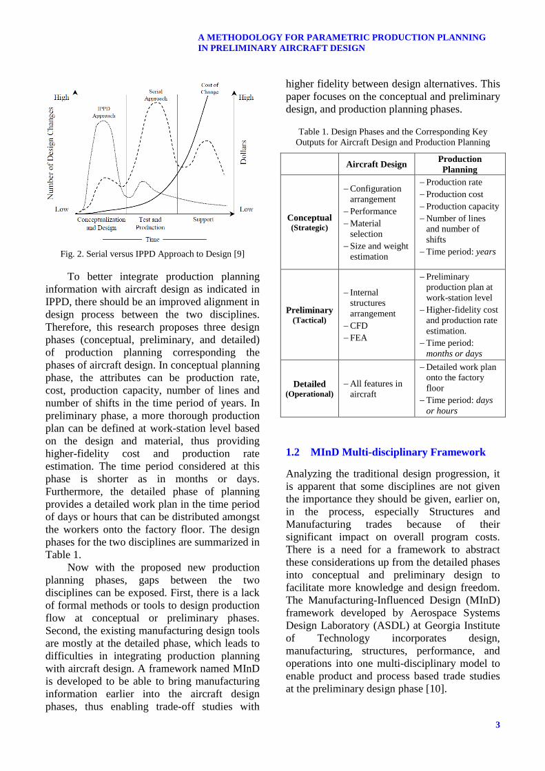
Traditionally, the aircraft manufacturing process
has been separate from the aircraft design.
Manufacturers develop production plans after
the design concept is chosen using a serial
process with an “over the wall” mentality [8].
Manufacturers would attempt to make the
product only to discover it may or may not be
feasible. This would result in costly, unwanted
design changes as illustrated in Fig. 2 [9]. In
recent years, there have been efforts to change
that mentality with integrated product teams
(IPT), and the methodology of Integrated
Product and Process Design (IPPD) is becoming
more widely accepted and practiced.
3
A METHODOLOGY FOR PARAMETRIC PRODUCTION PLANNING
IN PRELIMINARY AIRCRAFT DESIGN
Fig. 2. Serial versus IPPD Approach to Design [9]
To better integrate production planning
information with aircraft design as indicated in
IPPD, there should be an improved alignment in
design process between the two disciplines.
Therefore, this research proposes three design
phases (conceptual, preliminary, and detailed)
of production planning corresponding the
phases of aircraft design. In conceptual planning
phase, the attributes can be production rate,
cost, production capacity, number of lines and
number of shifts in the time period of years. In
preliminary phase, a more thorough production
plan can be defined at work-station level based
on the design and material, thus providing
higher-fidelity cost and production rate
estimation. The time period considered at this
phase is shorter as in months or days.
Furthermore, the detailed phase of planning
provides a detailed work plan in the time period
of days or hours that can be distributed amongst
the workers onto the factory floor. The design
phases for the two disciplines are summarized in
Table 1.
Now with the proposed new production
planning phases, gaps between the two
disciplines can be exposed. First, there is a lack
of formal methods or tools to design production
flow at conceptual or preliminary phases.
Second, the existing manufacturing design tools
are mostly at the detailed phase, which leads to
difficulties in integrating production planning
with aircraft design. A framework named MInD
is developed to be able to bring manufacturing
information earlier into the aircraft design
phases, thus enabling trade-off studies with
higher fidelity between design alternatives. This
paper focuses on the conceptual and preliminary
design, and production planning phases.
Table 1. Design Phases and the Corresponding Key
Outputs for Aircraft Design and Production Planning
Aircraft Design Production
Planning
Conceptual (Strategic)
Configuration
arrangement
Performance
Material
selection
Size and weight
estimation
Production rate
Production cost
Production capacity
Number of lines
and number of
shifts
Time period: years
Preliminary (Tactical)
Internal
structures
arrangement
CFD
FEA
Preliminary
production plan at
work-station level
Higher-fidelity cost
and production rate
estimation.
Time period:
months or days
Detailed (Operational)
All features in
aircraft
Detailed work plan
onto the factory
floor
Time period: days
or hours
1.2 MInD Multi-disciplinary Framework
Analyzing the traditional design progression, it
is apparent that some disciplines are not given
the importance they should be given, earlier on,
in the process, especially Structures and
Manufacturing trades because of their
significant impact on overall program costs.
There is a need for a framework to abstract
these considerations up from the detailed phases
into conceptual and preliminary design to
facilitate more knowledge and design freedom.
The Manufacturing-Influenced Design (MInD)
framework developed by Aerospace Systems
Design Laboratory (ASDL) at Georgia Institute
of Technology incorporates design,
manufacturing, structures, performance, and
operations into one multi-disciplinary model to
enable product and process based trade studies
at the preliminary design phase [10].

SUNDARESAN, TANG, CEISEL, MAVRIS
4
As seen in Fig. 3, the disciplines involved
in MInD are structures, aerodynamics,
manufacturing cost estimation, production
planning, supply chain, and risk analysis. They
are linked together with the aircraft design
variables in a modeling and simulation (M&S)
environment. MInD takes in top level inputs
such as outer mold line (OML) variables and
production quantity. With the help of a
parametric structural optimization tool, rules of
thumb (simple equations that relate detailed part
dimensions and quantities to OML dimensions),
and a high fidelity manufacturing cost model, it
calculates outputs involving performance
metrics, internal structure parameters, total
number of parts required, part thicknesses,
labor times and costs per part for fabrication,
sub-assembly, and final assembly. Design of
experiments and surrogate modeling are applied
to provide the back-end data in order to
construct the front-end graphical user interface
(GUI) called Manufacturing-Influenced Design
Space Exploration Tool (MInDSET).
The production planning research
discussed in this paper serves a critical part of
the framework. Production planning has not
traditionally been taken into consideration until
after the detailed design phase when a design
concept is finalized. The MInD framework
helps abstract the effects of manufacturing and
design choices on production planning earlier
on in the design process.
2 Research Methodology
The objective of the proposed methodology for
parametric production planning is to integrate
aircraft design and production planning into a
parametric multi-disciplinary model in order to
conduct design and producibility trades during
preliminary phase. The methodology consists of
two main parts. The first part is a parametric
equipment and tooling model which provides
various production process scenarios and
estimates recurring and nonrecurring tooling
costs, number of tools, and tooling capacity for
each design. The second part consists of a
production planning optimization model which
optimizes the aircraft manufacturing flow by
minimizing total cost to meet demand under
different constraints. Moreover, design of
experiments and surrogate modeling techniques
are applied to parameterize the models. The
complete data flow through the models is shown
in Fig. 4. The three key enablers to this
methodology are SEER-MFG, IBM ILOG
LogicNet Plus XE (LNP), and surrogate
Structural
Validation –
Industry Practices
Manuf
TranslatorParametric
Geometry
Production
Planning
Optimization
Key Economic VariablesMInDSET GUI
Cash FlowRisk
Assessment
@RISK
Fabrication Cost Model
by Part + Assembly
Cost Model
Manufacturing Costs
RDT&E /
O&S Costs
Performance
Data
Aircraft
Performance
(FLOPS)
RDT&E and O&S Cost
ModelAero Analysis
(VORLAX, VSP,
FRICTION)
Surrogates
Parametric
FEM
Detailed
Structural/
Manufacturing
Data Translator
Structural
OptimizationDesign
Variables
Supply
Chain
Optimization
Supplier &
Logistics
Cost
Prod Cycle
Time, Tooling,
& Capital Cost
Fig. 3. MInD Multi-disciplinary Framework

5
A METHODOLOGY FOR PARAMETRIC PRODUCTION PLANNING
IN PRELIMINARY AIRCRAFT DESIGN
modeling. In the following sections, each part of
the methodology will be described in further
detail.
2.1 Definitions and Assumptions
Several key terms used in this methodology are
defined here. They are important in scoping the
models in Section 2.2.
Equipment: It includes all general
purpose machinery such as autoclaves,
non-destructive inspection equipment,
milling machines, presses, routers, etc.
The parametric equipment and tooling
model accounts for the acquisition and
installation costs for all equipment [11].
Non-Recurring Tooling: It refers to the
tools designed solely for use on a
particular airframe program. It includes
layup tools, autoclave tools, assembly
tools, dies, jigs, fixtures, etc.
Nonrecurring tooling hours are those
required to plan fabrication and
assembly operations and to design,
fabricate, assemble, and install the initial
set of tools required for the planned
production rate [11].
Recurring Tooling: It refers to all of the
labor and tooling costs associated with
tooling replacement, modifications,
repair, and maintenance [11].
This methodology is designed to aid
enterprise level decision making for innovative
designs, so it is focused at late conceptual and
early preliminary phases of aircraft design and
production planning when the program is still in
its formative stages and majority of the costs are
not committed. The manufacturing facility is
assumed to be unconstrained. At the time of the
publication, the demand is modeled as a
uniform distribution, i.e., constant demand for
every production year from the start to the end.
Variable demand will be considered in future
research as explained in the conclusion section.
For labor hours available, it is assumed that
there are 250 working days in a year and three
shifts of eight hours a day. The production
planning time period is on yearly basis. Labor
times for the manufacturing processes are
calculated from empirical data in SEER-MFG,
which is a commercially available tool that was
created under the U.S. government’s
Composites Affordability Initiative (CAI) and
contains a large product and process knowledge
base attained from many major aerospace
manufacturers [12].
Fig. 4. The Data Flow Through Each Model in the Parametric Production Planning Methodology

SUNDARESAN, TANG, CEISEL, MAVRIS
6
2.2 Parametric Production Planning
Methodology
2.2.1 Parametric Equipment and Tooling
Model
As mentioned in previous sections, the first part
of the methodology is a parametric equipment
and tooling model. Its function is to provide
critical inputs to the production planning
optimization model in the form of recurring &
non-recurring tooling costs, equipment
acquisition and installation costs, and tooling
capacity. The model is designed to
parametrically select appropriate tooling and
equipment required for a particular
manufacturing process selected using Microsoft
Excel. The model consists of four major steps
explained as follows.
The first step consists of reviewing the
design. This step allows the user to set the
design concept by entering specifications such
as part dimensions, material type, ply count,
number of fasteners, part thickness, number of
stiffeners, along with certain manufacturing and
production cost levers such as learning curves,
labor rates for assembly and fabrication,
production quantity, and material costs. Besides
part fabrication specifications, this step also
outlines the design assembly definition. The
Excel front-end also has a visual representation
of each component of the design being
evaluated. The purpose of this step is to provide
a section where the user can review the design
concept.
The second step is to determine equipment
and tool set scenarios. The objective of this step
is to select appropriate tooling and equipment
scenarios per design concept for a particular
combination of manufacturing process and
material. Tooling and equipment selection
depends on a number of different factors such as
fabrication, sub-assembly, final assembly
process, and for composite designs, resin type,
thermal conductivity, thermal coefficient of
expansion, and heat resistance. Another major
factor that affects tooling selection is production
quantity. A small production quantity usually
will not justify the acquisition of more
expensive advanced tooling and equipment. On
the other hand, the advanced tooling and
machinery can be advantageous for a large
production quantity. The scenarios are based on
an equipment and tooling library set up in the
back-end of the model.
The third step is to determine capacity and
costs. The objective of this step is to compute
all the costs and labor hours depending on the
design, manufacturing process, tooling, and
equipment. Equipment cost data is sourced from
actual aerospace equipment vendors in the
industry. Along with acquisition cost, the Excel
tool also accounts for equipment installation
costs by allowing the user (or a subject matter
expert) to enter an equipment installation cost to
acquisition cost ratio. The tool uses this ratio to
calculate the installation costs and adds it up to
the acquisition cost to give an aggregate
equipment cost figure for each part. Non-
recurring tooling costs are calculated by using
Response Surface Equations (RSE) built around
empirical data in SEER-MFG. In composite
manufacturing, the tooling used in the layup and
cure processes needs to be replaced every so
often because of damage caused by the
numerous high pressure and temperature cycles
it is made to go through [4]. In most instances,
the cost for replacing a tool or changing a few
parts will not be the same as that for initial
tooling procurement. This is accounted for in
the model by the replacement cost ratio which is
the ratio of the replacement cost to initial
procurement cost. Recurring tooling costs or
replacement costs are calculated within the
Excel tool as a function of tooling replacement
rate, replacement cost ratio and production
quantity desired.
The final step is to feed manufacturing
scenarios to the production optimization model.
The objective of this step is to bring together all
the critical metrics calculated by the model and
display them in a format that can be input to the
production planning optimization model which
is described in the next section.
2.2.2 Production Planning Optimization Model
The production planning optimization model
optimizes the aircraft manufacturing flow by
minimizing total cost incurred to meet demand
under different constraints. It is modeled using

7
A METHODOLOGY FOR PARAMETRIC PRODUCTION PLANNING
IN PRELIMINARY AIRCRAFT DESIGN
IBM ILOG LogicNet Plus XE (LNP) [13].
ILOG LNP is a commercial software package
for production planning and supply chain
network optimization. The model built in LNP
accepts inputs in the format of databases
consisting of various forms, and performs
optimization routines to obtain the optimized
configuration of the manufacturing systems.
Once the manufacturing scenario has been
finalized and the related equipment and tooling
information are generated by the parametric
equipment and tooling model, the work stations
required to manufacture the designed parts are
modeled in LNP. Relevant information about
the design and manufacturing processes are
entered into data forms. Information about the
design being manufactured is fed to the Product
Details form. The Bill of Materials form
translates the work breakdown structure of the
design to all the components that need to be
produced through the manufacturing systems.
For example, this form is where the number of
spars (2), ribs (20) and skin-stringer panels (2)
required to assemble a single wing box is
modeled. Specifics about the corresponding
work stations derived from BoM are entered in
the Line Details form respectively. Production
capacity and costs are modeled for each
combination of components and assigned work
station in the Production Information form and
Overall Capacity form. The model is setup in
such a way that there is a penalty factor of 1.5
associated with production costs incurred in the
third shift compared to the first and second
shifts, respectively. The oven curing work
station is modeled in the Tanks form with inputs
including cycle time and number of components
that can be cured simultaneously based on
industry subject matter experts’ opinion.
After the inputs are entered into the
database forms, the model performs the
optimization routine and generates the
optimized production facility configuration with
outputs including number of work stations,
number of shifts, production rate, total cost,
total profit, capital costs, production costs, labor
costs, and facility costs.
2.2.3 Parameterization
For parameterization of the models described
above, a design of experiments (DoE) needs to
be first set up to model the design space so that
a surrogate model can be ensured to represent
the complicated outputs of LNP. Table 4 lists
the input variables with their ranges that were
varied in the DoE. The main advantage of using
a DoE is that a maximum amount of knowledge
is gained with a minimum expenditure of
experimental effort such as runs or computation
time. DoE has different designs such as full
factorial, Latin Hypercube Sampling (LHS),
Box-Behnken, and Central Composite Design as
shown in Fig. 5. For this research, LHS is
chosen for the DoE based on its space-filling
characteristics [14]. Commercially available
software ModelCenter by Phoenix Integration
[15] is used to set up the M&S environment
where the inputs, LNP, and outputs are linked in
order to automatically run all the cases
generated by LHS.
After the DoE is generated, surrogate
models use various techniques such as
polynomial response surface methods, neural
network, and Gaussian process models to
capture the relationships between the input
variables and the responses or metrics of
interests. Table 5 lists the responses that are of
this research’s interests. Due to the complex
nature of the data generated from the LHS DoE,
the surrogate modeling technique that is best
applied to this research is yet to be determined
at the time of publication of this paper, as stated
below as a part of future research in Section 4.

SUNDARESAN, TANG, CEISEL, MAVRIS
8
Fig. 5. Graphical Representations of Common DoE’s
3 Case Study
This methodology was applied to the F-86F
fighter aircraft as seen in Fig. 6 [16]. The F-86F
wing box was chosen due to the variety of
structural shapes and choice of manufacturing
processes seen within the wing box, and its
strong relation with overall aircraft
performance. The associated data is non-
proprietary for research purposes. The scope of
the case study is limited to the primary wing
box components comprising of spars, ribs and
skin-stringer panels. Table 2 lists the baseline
design characteristics of the F-86F wing box in
this case study. The design is an advanced
composite wing box that exhibits a high level of
integration realized through the use of co-
bonding and paste-bonding manufacturing
methods along with hand layup techniques. The
baseline manufacturing process is illustrated in
Fig. 7.
According to the steps stated in Section
2.2.1, RSEs created using SEER-MFG were
used to compute non-recurring tooling, labor
and material costs; and labor times for the wing
box baseline design. Equipment and tooling
selection was made based on the manufacturing
process. Non-recurring tooling costs were
calculated as a function of a tooling replacement
rate of 100 units. Costing information for
equipment that consisted of manual trimming
devices, ovens, and laser ultrasonic testing and
manual hand-held devices for NDI was sourced
from aerospace grade equipment vendors from
industry.
Table 2. The Baseline Design Characteristics of the F-86F
Wing Box
Parameter Baseline Value
Wing Area (ft2) 313.3
Aspect Ratio 4.88
Sweep (deg) 35
Taper Ratio 0.514
Range (nm) 804
Rib Spacing (in) 12
Fig. 6. F-86F Sabre 3-view Engineering Diagram [16]

9
A METHODOLOGY FOR PARAMETRIC PRODUCTION PLANNING
IN PRELIMINARY AIRCRAFT DESIGN
Table 3. The Optimized Outputs Over Different
Production Periods
Production
Period 10 Years
15 Years
(Baseline) 20 Years
No. of work
stations 13 11 11
No. of Shifts
for all work
stations
28 21 17
Production
Cost ($/yr) 46,380,500 28,673,300 21,315,200
After the outputs from the parametric
equipment and tooling model were generated,
the production planning optimization model was
set up in LNP. The production of the wing box
structure was modeled as a 4 stage
manufacturing process in LNP as shown in Fig.
8. They are defined as work stations which are
component layup, oven curing, NDI, and wing
box final assembly. As shown in Fig. 8, the Bill
of Materials (BOM) is visualized for the
advanced composite wing box case study design
which constrains the LNP model by setting a
minimum lot increment size for each wing box
final assembly. A total production quantity of
4000 wing boxes was considered over a
production life of 15 years as the baseline
production scenario for the case study.
Table 3 shows the optimized outputs for
number of work stations, number of shifts for all
work stations, and production cost for the
baseline wing box design over different
production period scenarios. These key outputs
give the engineer insight into the implications of
top level design and management decisions. A
shorter production period implies that more
units would have to be produced each year
causing the optimization model to open more
work stations to keep up with the demand. This
is why we see an increase in the number of
work stations, shifts, and the associated
production costs as the production period
reduces. In future work, optimal production rate
for profitability and robust design to demand
variability will be investigated.
3.1 Sensitivity Analysis
A sensitivity analysis was carried out on LNP to
identify the significant input variables in the
production planning optimization model. LHS
DoE is performed in the M&S environment
Fig. 7. The Baseline Manufacturing Process for the Advanced Composite Wing Box Design

SUNDARESAN, TANG, CEISEL, MAVRIS
10
involving LNP. The results of the analysis are
shown in Pareto plots (Fig. 9 – Fig.14) that
identify the contribution from the inputs to the
response’s variability. A Pareto plot is a
statistical tool that “displays the severity
(frequency) of variables and is ordered from top
to bottom in decreasing order” [17], allowing
the designer to understand which variables have
significant impact on the response variability in
the model. It is based on Pareto’s Law which
states that “80% of the total of any group will
come from 20% of the components of that
group” [18].
The input variables and ranges are enlisted
in Table 4 for the baseline wing box design. The
demand range was selected to explore
production period from 10-20 years. The ranges
for profit margin and facility cost per square
foot were picked based on industry subject
matter expert opinion. Labor hour available
ranges were chosen to study the effect of
varying the number of workers at each work
station. Each worker contributes 2000 hours per
shift at each work station in one year based on
the assumption of 250 working days each year.
Based on number of inputs, 1400 cases for the
DoE were generated, and LNP was run within
the ModelCenter M&S environment in batch
mode with each case taking 2-3 minutes on an
average. Table 5 shows the responses and their
significant variable drivers.
As expected, market demand was noted to
be the most significant driver in this study.
From the BOM data, it is apparent that the rib is
the most constraining product. This is confirmed
by Pareto plots in Fig. 10 and 12 which show
the effect of rib labor hours available on tooling
and equipment costs incurred, and facility area
required for new work stations in the case study
scenario. The study helps us realize that, for the
particular case study being considered, having a
wing box design with lesser number of ribs will
relax the constraint rib manufacturing imposes
on the overall production plan which in turn will
help meet higher demand and reduce overall
costs. This result seems intuitive since a lower
number of ribs would require a reduced amount
of time for final assembly operations. The
optimization objective within LNP was set to
minimize total cost incurred and as a result, the
model minimizes the number of work stations it
opens in order to keep the facility costs low.
Hence, facility cost per square foot area
emerged as another significant driver. Further,
the trends seen in Fig. 11 and Fig. 13 depict the
effect demand has on production cost and
revenue generated thus verifying logical
behavior of the model. For future work, the
production levers shown will be incorporated
into design. For instance, a wing at preliminary
level could be constrained by a maximum rib
quantity and facility square footage in order to
maximize production rate and minimize cost,
while maximizing performance.
Fig. 8. Bill of Materials and the Corresponding Work Stations in Production Planning

11
A METHODOLOGY FOR PARAMETRIC PRODUCTION PLANNING
IN PRELIMINARY AIRCRAFT DESIGN
Table 4. DoE Input Variables
Input Variable Min.
Value
Max.
Value
Demand
(No. of Wing Boxes/year) 200 400
Profit Margin (%) 5 10
Facility Cost per Sq. Ft. ($/year) 800 1000
Rib Labor Hours Available (Per
year) 14000 18000
Spar Labor Hours Available (Per
year) 14000 18000
Skin-Stringer Labor Hours
Available (Per year) 14000 18000
Final Assembly Labor Hours
Available (Per year) 8000 12000
Table 5. DoE Output Variables and the Corresponding
Significant Drivers from the Sensitivity Analysis
Output
Response Significant Drivers
Demand
Satisfied
Demand
Final Assembly Labor Hours
Available
Facility Cost Per Sq. Ft.
Number of Work
Stations
Demand
Rib Labor Hours Available
Production Cost Demand
Facility Cost Per Sq. Ft.
Tooling &
Equipment Cost
Demand
Rib Labor Hours Available
Revenue Demand
Profit Margin
Final Assembly
Number of Shifts
Demand
Final Assembly Labor Hours
Available
Fig. 9. Pareto Plot for the Output Demand Satisfied
Fig. 10. Pareto Plot for the Output Number of Work
Stations
0%
80%
Dem
an
d
Fin
al
Assem
bly
lab
or
hrs
av
ailab
le
Facilit
y c
ost/
sq
.ft.
Rib
lab
or
hrs
av
ailab
le
Pro
fit
Marg
in
Sp
ar
lab
or
hrs
av
ailab
le
Skin
-Str
ing
er
lab
or
hrs
av
ailab
le
Eff
ect
Siz
e
0%
80%
Dem
an
d
Rib
lab
or
hrs
ava
ila
ble
Faci
lity
co
st/s
q.f
t.
Skin
-Str
inge
r la
bo
r h
rs a
vail
ab
le
Fin
al A
ssem
bly
lab
or
hrs
ava
ilab
le
Spa
r la
bo
r h
rs a
vail
ab
le
Pro
fit M
arg
in
Eff
ect
Siz
e

SUNDARESAN, TANG, CEISEL, MAVRIS
12
Fig. 11. Pareto Plot for the Output Production Cost
Fig. 12. Pareto Plot for the Output Tooling and
Equipment Cost
Fig. 13. Pareto Plot for the Output Revenue
Fig. 14. Pareto Plot for the Output Final Assembly
Number of Shifts
0%
80%D
ema
nd
Faci
lity
co
st/s
q.f
t.
Skin
-Str
inge
r la
bo
r h
rs a
vail
ab
le
Spa
r la
bo
r h
rs a
vail
ab
le
Fin
al A
ssem
bly
lab
or
hrs
ava
ilab
le
Pro
fit M
arg
in
Rib
lab
or
hrs
ava
ila
ble
Eff
ect
Siz
e
0%
80%
Dem
an
d
Rib
lab
or
hrs
ava
ila
ble
Faci
lity
co
st/s
q.f
t.
Skin
-Str
inge
r la
bo
r h
rs a
vail
ab
le
Spa
r la
bo
r h
rs a
vail
ab
le
Fin
al A
ssem
bly
lab
or
hrs
ava
ilab
le
Pro
fit M
arg
in
Eff
ect
Siz
e
0%
80%
Dem
an
d
Pro
fit M
arg
in
Faci
lity
co
st/s
q.f
t.
Fin
al A
ssem
bly
lab
or
hrs
ava
ilab
le
Spa
r la
bo
r h
rs a
vail
ab
le
Skin
-Str
inge
r la
bo
r h
rs a
vail
ab
le
Rib
lab
or
hrs
ava
ila
ble
Eff
ect
Siz
e
0%
80%
Dem
an
d
Fin
al A
ssem
bly
lab
or
hrs
ava
ilab
le
Faci
lity
co
st/s
q.f
t.
Pro
fit M
arg
in
Skin
-Str
inge
r la
bo
r h
rs a
vail
ab
le
Rib
lab
or
hrs
ava
ila
ble
Spa
r la
bo
r h
rs a
vail
ab
le
Eff
ect
Siz
e

13
A METHODOLOGY FOR PARAMETRIC PRODUCTION PLANNING
IN PRELIMINARY AIRCRAFT DESIGN
4 Conclusions and Future Research
The methodology for parametric production
planning enables stake holders to conduct
performance, and production trades by
leveraging high fidelity manufacturing models
and knowledge about the manufacturing
processes in conceptual and preliminary design.
The main parts of the methodology are
parametric equipment and tooling model, and
production planning optimization model. Design
of experiments and surrogate modeling
techniques are applied to parameterize the
models.
A case study of the F-86F wing box design
using advanced composite material and
advanced manufacturing process is presented. It
demonstrates the capability of the methodology
to generate equipment and tooling knowledge as
well as the optimized production plans given
different labor and capacity constraints. A
sensitivity analysis was performed using DoE
and the M&S environment, and the significant
input variables in the optimization model are
identified to facilitate constructing surrogate
models in the next steps.
This methodology breaks new grounds in
integrating production planning with aircraft
design in the early design stages, and in
enabling us to minimize cycle time, cost, and
risk while maximizing performance and
production rate. Another important value is the
application of surrogate modeling techniques to
production planning.
Future research involves running a DOE to
explore the aircraft wing box design space to
find a design point that is most robust to
demand variability through a Monte Carlo
analysis. Surrogate models for production
planning will be created and integrated in order
to enable rapid design and manufacturing trades
within the MInD Framework.
Acknowledgements
This research is funded by Boeing Research and
Technology (BR&T) organization. We would
like to express our most sincere gratitude to
John Griffith, Charles Saff, Steven Wanthal, and
Keith Rupel from BR&T, and Dr. Michael
Watson from IBM's ILOG Optimization and
Supply Chain division for giving us advice and
guidance throughout the project. We would also
like to extend many thanks to Dr. Zhimin Liu
for his advice and the MInD Grand Challenge
Teams at the ASDL for providing us with some
of the necessary data.
References
[1] Lu K. The future of metals. Science, Vol. 328, No.
5976, pp. 319-320,2010.
[2] Dasgupta P and Dodge W. High Fliers: creating the
talent, leadership, culture and organization
capabilities to meet the new business challenges of
the aerospace and defense industry. Accenture, 2010.
[3] Mavris D N, DeLaurentis D A, Bandte O and Hale M
A. A stochastic approach to multi-disciplinary
aircraft analysis and design. The 36th Aerospace
Sciences Meeting & Exhibit, Reno, NV, AIAA 1998-
0912, 16, 1998.
[4] Campbell F C. Manufacturing processes for
advanced composites. Oxford: Elsevier Advanced
Technology, 2004.
[5] Quoted by ASC Process Systems. <www.aschome.
com, 2011>
[6] Kamal S, Fan I, Cooper S and Williams G. Design
for manufacture in the aerospace extended enterprise.
World Class Design to Manufacture, Vol. 2, No. 2,
pp. 28–33, 1995.
[7] Raymer D P. Aircraft design: a conceptual approach.
4th
edition, American Institute of Aeronautics and
Astronautics, Inc, 2006.
[8] Rush C, Falque J and McRitchie K. Real time cost
impact assessment of composite and metallic design
alternatives. Galorath Incorporated, El Segundo,
California, 2003.
[9] DoD guide to integrated product and process
development. Version 1.0, Office of the Under
Secretary of Defense, February 5, 1996.
[10] Liu Z, Witte P, Ceisel J, Mavris D N. An approach to
infuse manufacturing considerations into aircraft
structural design. Society for the Advancement of
Material and Process Engineering 2011, Long
Beach, CA, 16, 2011.
[11] Younossi O, Kennedy M and Graser J C. Military
airframe costs: the effects of advanced materials and
manufacturing processes. RAND Corporation, 2001.
[12] Galorath D. State department lifts ITAR restrictions
on SEER for manufacturing aerostructures plug-in.
Galorath, accessed on July 5, 2011. <http://www.galo
rath.com/wp/statedepartment-lifts-itar-restrictions-
on-seer-for-manufacturing-aero-structures-plug-
in.php>
[13] IBM ILOG LogicNet Plus XE homepage.
<http://www-01.ibm.com/software/integration/sca/

SUNDARESAN, TANG, CEISEL, MAVRIS
14
logicnet-plus-xe/>
[14] Keane A J and Nair P B. Computational approaches
for aerospace design: the pursuit of excellence. John
Wiley & Sons, Ltd, 2005.
[15] Pheonix Integration ModelCenter 10.0 homepage.
<http://www.phoenix-int.com/software/phx_
modelcenter.php>
[16] F-86F Sabre 3-view engineering diagram.
<http://www.fiddlersgreen.net/
models/aircraft/North-American-F86.html>
[17] Kirby M R. A methodology for technology
identification, evaluation, and selection in conceptual
and preliminary aircraft design. Doctor of
Philosophy Thesis, Georgia Institute of Technology,
2001.
[18] Dieter G E. Engineering design: a materials and
processing approach. 2nd
edition, McGraw-Hill, New
York, 1991.
Copyright Statement
The authors confirm that they, and/or their company or
organization, hold copyright on all of the original material
included in this paper. The authors also confirm that they
have obtained permission, from the copyright holder of
any third party material included in this paper, to publish
it as part of their paper. The authors confirm that they
give permission, or have obtained permission from the
copyright holder of this paper, for the publication and
distribution of this paper as part of the ICAS2012
proceedings or as individual off-prints from the
proceedings.