a methodology - abb · pdf file1.0 methodology page 3 1.1 sil achievement ... after performing...
TRANSCRIPT

A Methodologyfor the achievement of target SIL
©A
BB
Lim
ited
2009

2
CONTENTS
1.0 Methodology Page 3
1.1 SIL Achievement - A Definition Page 4
1.2 Responsibilities Page 5
1.3 Identification of Hazards and SIL Determination Page 7
1.4 Safety Requirements Page 8
1.5 Design and Engineering Page 14
1.6 Demonstrating SIL Achievement Page 18
1.7 Summary Page 24
References Page 26
About the author Page 27
For more information, contact Stuart Nunns, UK Safety Lead Competency Centre, [email protected]

3
The purpose of this chapter is to describe amethodology by which an organisation candemonstrate that the target Safety IntegrityLevel (SIL) of a safety instrumented function hasbeen achieved. Throughout this chapter thismethodology is referred to as SIL Achievement.
Successful demonstration that the target SIL for a safety instrumented function has beenachieved is reliant on many aspects of theoverall safety lifecycle, such as Hazard and Risk Assessment, SIL Determination, SafetyRequirements Allocation, and Realisation -phases 1 to 9 of the IEC 61508 safety lifecycle.These phases are described in detail elsewherein this manual.
The evidence required in order to demonstratethat a safety instrumented system functionmeets its target SIL (i.e. the SIL Achievementexercise) is far more than a quantitativeexercise, based solely on target failure measure.Architectural constraints and Systematiccapability must also be taken into account.How all of this data is identified, interpreted andused for SIL achievement is described in thefollowing sections.
1.0 METHODOLOGY

4
1.1 SIL ACHIEVEMENT – A DEFINITION
SIL Achievement is a demonstration that foreach Safety Instrumented Function, the targetSIL, as derived from SIL Determination, hasbeen met in accordance with the requirementsof IEC61508. Achievement of SIL, for a safetyinstrumented function, is dependent on thefollowing parameters;
• Architectural Constraint, in terms of- Safe Failure Fraction (SFF) and- Hardware Fault Tolerance (HFT)
• Target Failure Measure, expressed as either:- Pfd, or- Dangerous Failure Rate (hour)
• Systematic Capability, in terms of- Each element* that carries out the
safety function- The method by which the safety
instrumented function was designed and implemented
* An element relates to a piece of equipment,such as a limit switch or a barrier. Multipleelements are connected to form the sub-systems (Sensor, Logic Solver and Output) ofa safety instrumented function. Refer tosection 1.5 for further information.
Only when a safety instrumented function meets the criteria set by IEC 61508 in terms ofarchitectural constraint, target failure measureand systematic capability, can the target SIL be said to be achieved.
The following sections provide guidance on;• Responsibilities – the responsibilities of End
User/Operators and Engineering/Equipmentsuppliers in providing, compiling anddemonstrating that the target SIL has been achieved
• Identification of Hazards and SILDetermination – identifying the safetyinstrumented functions, and assigning a target SIL
• Safety Requirements – The importance of Safety Requirements in specifying thesafety instrumented function
• Design and Engineering – the importance of correctly specifying and integrating theequipment to be used to perform the safetyinstrumented function
• SIL Achievement – how to demonstrate that SIL has been achieved for a specifiedsafety instrumented function in respect of a Safety Instrumented System.
5
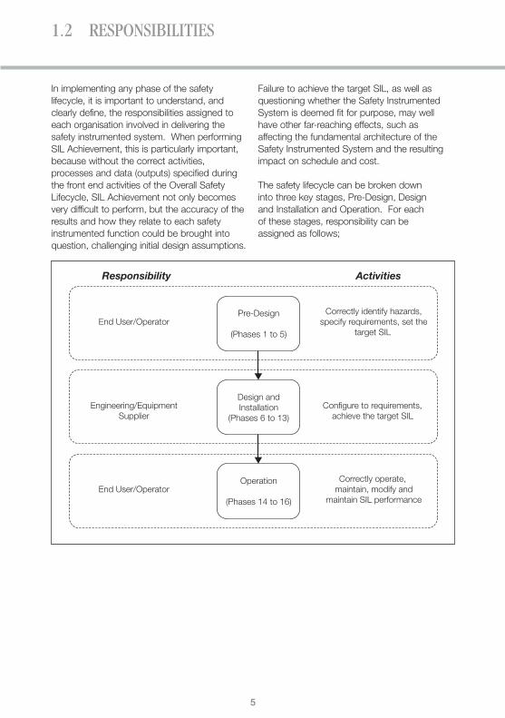
In implementing any phase of the safetylifecycle, it is important to understand, andclearly define, the responsibilities assigned toeach organisation involved in delivering thesafety instrumented system. When performingSIL Achievement, this is particularly important,because without the correct activities,processes and data (outputs) specified duringthe front end activities of the Overall SafetyLifecycle, SIL Achievement not only becomesvery difficult to perform, but the accuracy of theresults and how they relate to each safetyinstrumented function could be brought intoquestion, challenging initial design assumptions.
Failure to achieve the target SIL, as well asquestioning whether the Safety InstrumentedSystem is deemed fit for purpose, may wellhave other far-reaching effects, such asaffecting the fundamental architecture of theSafety Instrumented System and the resultingimpact on schedule and cost.
The safety lifecycle can be broken down into three key stages, Pre-Design, Design and Installation and Operation. For each of these stages, responsibility can be assigned as follows;
1.2 RESPONSIBILITIES
Responsibility Activities
End User/OperatorCorrectly identify hazards,
specify requirements, set thetarget SIL
Pre-Design
(Phases 1 to 5)
Engineering/EquipmentSupplier
Configure to requirements, achieve the target SIL
Design andInstallation
(Phases 6 to 13)
End User/OperatorCorrectly operate,
maintain, modify andmaintain SIL performance
Operation
(Phases 14 to 16)

6
1.2 RESPONSIBILITIES
• A System Integrator may be appointed by theEngineering/Equipment supplier to performthe design of the logic solver subsystem.The system integrator is responsible forengineering the logic solver in accordancewith the safety requirements, and followinggood practice as defined in IEC 61508 andIEC 61511 during the design engineeringprocess. It is the responsibility of theEngineering/Equipment supplier to provide allthe necessary information to the SystemIntegrator in order that the latter can build theSafety Instrumented System to meet thespecified functional safety requirements.
In terms of SIL Achievement, it is normally theresponsibility of the Engineering/Equipmentsupplier to demonstrate that the target SIL has been achieved for each safety function, but this is based on the premise that hazardshave been correctly identified and safetyrequirements correctly specified by the EndUser/plant operator.
It can be seen from the diagram, that eachorganisation has a responsibility to implementprocesses and to deliver packages of work tothe next organisation in the supply chain. For example, the End User or Operator has aresponsibility to provide sufficient information to the Engineering/Equipment Supplier to allow them to complete the design stage of the safety lifecycle.
Responsibilities may be delegated to thirdparties, for example:
• An Engineering/Procurement/Construction(EPC) company – operating in the genericrole of Engineering/Equipment Supplier (seeabove) may be appointed by the End User toperform pre-design; the EPC is responsiblefor delivering the required information to thenext organisation in the supply chain.

7
With reference to IEC61508-5 (clause A.2), theconcept of risk reduction, ‘is of fundamentalimportance in the development of the safetyrequirements specification for the E/E/PEsafety-related systems (in particular, the safetyintegrity requirements part of the safetyrequirements specification). The purpose ofdetermining the tolerable risk for a specifichazardous event is to state what is deemedreasonable with respect to both the frequency(or probability) of the hazardous event and itsspecific consequences. Safety-related systemsare designed to reduce the frequency (orprobability) of the hazardous event and/or theconsequences of the hazardous event.’
It is necessary that a hazard and risk analysisbe undertaken on the Equipment Under Control(EUC) and the EUC control system in order toidentify the process hazards; the risk resultingfrom the hazardous event(s) associated with theidentified hazard and, if necessary, identify whathas to be done (prevention and/or mitigation)and to what performance criteria, to ensure thatthe tolerable risk is achieved.
Further information relating to the concept oftolerable risk can be found in IEC61511-3 (Annex A).
To achieve functional safety it is necessary to determine:• What has to be done to prevent the
hazardous event(the safety function);• The required performance of each safety
function (the Safety Integrity Level).
Therefore, for each identified hazard, whichrequires a risk reduction measure, a safetyfunction is identified, which is required to meet aspecified (target) SIL. Typically Hazard andOperability Studies (HAZOP) are used to identifywhere protection is required and the safetyfunction required, whilst SIL determinationmethods are employed (such as LOPA or RiskGraph) to determine the required (target) SIL.These concepts are described in detailelsewhere in this handbook.
For example, after performing a HAZOP studyon the Equipment Under Control (EUC) and theEUC control system, the functionality of thesafety function shall be specified. For example:
‘In order to prevent the rupture of pressure tank VS-01, Valve V-01-01 must be openedwithin 2 seconds, when the pressure in vesselVS-01 rises to 2.6 bar’ This is the functionality of the safety function.
After performing the risk assessment, the safety integrity of the safety function shall be specified. For example:‘The safety integrity of the safety function mustbe SIL 1’This is the target SIL of the safety function.
In conclusion:‘In order to prevent the rupture of pressure tankVS-01, Valve V-01-01 must be opened within 2seconds, when the pressure in vessel VS-01rises to 2.6 bar’. The safety integrity of thesafety function shall be SIL 1’
An important concept here is that safetyintegrity is applied to a safety function, not tothe safety-related system so;• It is correct to say that ‘Safety Function x
requires a target SIL of y’• It would be incorrect to say that the ‘safety-
related system requires a target SIL of y’,without also providing the required safetyintegrity of each of the safety functionsexecuted by the safety-related system.
The safety function descriptions and theirassociated target SIL’s need to be provided tothe Engineering/Equipment Supplier, to enablethem to complete Phase 9 of the Overall Safety Lifecycle, and ultimately demonstrate SIL Achievement. The mechanism by whichthis information (functionality of the safetyfunction and safety integrity of the safetyfunction) is provided is through the SafetyRequirements Specification.
1.3 IDENTIFICATION OF HAZARDS AND SIL DETERMINATION

8
1.4 SAFETY REQUIREMENTS
For every Safety Instrumented System, it is theresponsibility of the end user/operator toprovide a Safety Requirements Specification tothe engineering/equipment supplier. This isidentified as Phase 4, Overall Requirements, inthe IEC 61508 safety lifecycle model.
Guidance is provided in IEC 61508 Part 2clause 7.2.3 regarding the content of the SafetyRequirements Specification, this isstrengthened, for the process industry, in IEC61511 part 1 clause 10.3.1. For completenessthis guidance is given below:
Ref Requirement to be considered/addressed
1 A description of all the safety instrumented functions necessary to achieve the required functional safety
2 Requirements to identify and take account of common cause failures
3 A definition of the safe state of the process for each identified safety instrumented function
4 A definition of any individually safe process states which, when occurring concurrently,create a separate hazard (for example, overload of emergency storage, multiple relief to flare system)
5 The assumed sources of demand and demand rate on the safety instrumented function
6 Requirement for proof-test intervals
7 Response time requirements for the SIS to bring the process to a safe state
8 The safety integrity level and mode of operation (demand/continuous) for each safetyinstrumented function
9 A description of SIS process measurements and their trip points
10 A description of SIS process output actions and the criteria for successful operation, for example, requirements for tight shut-off valves
11 The functional relationship between process inputs and outputs, including logic,mathematical functions and any required permissives
12 Requirements for manual shutdown
13 Requirements relating to energize or de-energize to trip
14 Requirements for resetting the SIS after a shutdown
15 Maximum allowable spurious trip rate
16 Failure modes and desired response of the SIS (for example, alarms, automatic shutdown)
17 Any specific requirements related to the procedures for starting up and restarting the SIS
18 All interfaces between the SIS and any other system (including the BPCS and operators)
19 A description of the modes of operation of the plant and identification of the safetyinstrumented functions required to operate within each mode
20 The application software safety requirements as listed in section 12.2.2 of IEC 61511-1(2003-01)
9
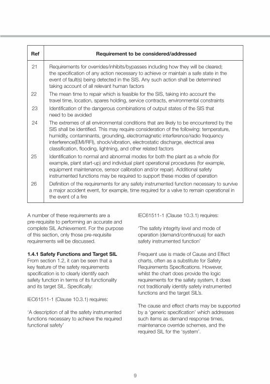
A number of these requirements are a pre-requisite to performing an accurate andcomplete SIL Achievement. For the purpose of this section, only those pre-requisiterequirements will be discussed.
1.4.1 Safety Functions and Target SILFrom section 1.2, it can be seen that a key feature of the safety requirementsspecification is to clearly identify each safety function in terms of its functionality and its target SIL. Specifically:
IEC61511-1 (Clause 10.3.1) requires:
‘A description of all the safety instrumentedfunctions necessary to achieve the requiredfunctional safety’
IEC61511-1 (Clause 10.3.1) requires:
‘The safety integrity level and mode of operation (demand/continuous) for each safety instrumented function’
Frequent use is made of Cause and Effectcharts, often as a substitute for SafetyRequirements Specifications. However,whilst the chart does provide the logicrequirements for the safety system, it does not traditionally identify safety instrumentedfunctions and the target SIL’s.
The cause and effect charts may be supportedby a ‘generic specification’ which addressessuch items as demand response times,maintenance override schemes, and therequired SIL for the ‘system’.
Ref Requirement to be considered/addressed
21 Requirements for overrides/inhibits/bypasses including how they will be cleared; the specification of any action necessary to achieve or maintain a safe state in theevent of fault(s) being detected in the SIS. Any such action shall be determined taking account of all relevant human factors
22 The mean time to repair which is feasible for the SIS, taking into account the travel time, location, spares holding, service contracts, environmental constraints
23 Identification of the dangerous combinations of output states of the SIS that need to be avoided
24 The extremes of all environmental conditions that are likely to be encountered by theSIS shall be identified. This may require consideration of the following: temperature,humidity, contaminants, grounding, electromagnetic interference/radio frequencyinterference(EMI/RFI), shock/vibration, electrostatic discharge, electrical areaclassification, flooding, lightning, and other related factors
25 Identification to normal and abnormal modes for both the plant as a whole (forexample, plant start-up) and individual plant operational procedures (for example,equipment maintenance, sensor calibration and/or repair). Additional safetyinstrumented functions may be required to support these modes of operation
26 Definition of the requirements for any safety instrumented function necessary to survivea major accident event, for example, time required for a valve to remain operational inthe event of a fire

10
1.4 SAFETY REQUIREMENTS
Two important questions can be asked: 1. How can individual safety instrumented
functions (SF) be identified? Does cause 1and 2 or only cause 1 constitute the safetyinstrumented function?
Consider the following extract from a generic specification:‘The ESD system shall be a PLC based systemand shall be certified by TUV for safety relatedinterlocks for SIL 3 as a minimum’
2. What is the target SIL of the safetyinstrumented function? The basicspecification stated that the PLC system was required to be certified to SIL3.
Cause and Effect Emergency Shutdown Logic - Pressure Vessel VS-01
Number
1
2
3
High Pressure in Vessel 01
High Temp in Vessel 01
Vessel 01 HI Out Press
PID-01-14
PID-01-14
PID-01-14
PT-01-01
TT-01-01
PT-01-02 X X
X
X
X
Description P&ID Tag
Tag
M-0
1-01
V-01
-01
V-01
-07
V-01
-09
P&
ID
PID
-01-
14
PID
-01-
14
PID
-01-
14
PID
-01-
14
Des
crip
tion
Sto
pD
isch
arge
Pum
p
Ope
nVe
ntVa
lve
Ope
nC
oolin
gVa
lve
Clo
seIn
letV
alve

11
If a comprehensive safety requirementsspecification is produced, we would know that:
‘In order to prevent the rupture of pressure tankVS-01, Valve V-01-01 must be opened within 2seconds, when the pressure in vessel VS-01rises to 2.6 bar’
and
‘The safety integrity of the safety instrumentedfunction must be SIL 1’
This provides a clear description of the requiredfunctionality of the safety instrumented functionand the target SIL for the safety function.
Number
1
2
3
High Pressure in Vessel 01
High Temp in Vessel 01
Vessel 01 HI Out Press
PID-01-14
PID-01-14
PID-01-14
PT-01-01
TT-01-01
PT-01-02 X X
X
X
X
Description P&ID Tag
Tag
M-0
1-01
V-01
-01
V-01
-07
V-01
-09
P&
ID
PID
-01-
14
PID
-01-
14
PID
-01-
14
PID
-01-
14
SF ?
Number
1
2
3
High Pressure in Vessel 01
High Temp in Vessel 01
Vessel 01 HI Out Press
PID-01-14
PID-01-14
PID-01-14
PT-01-01
TT-01-01
PT-01-02 X X
X
X
X
Description P&ID Tag
Tag
M-0
1-01
V-01
-01
V-01
-07
V-01
-09
P&
ID
PID
-01-
14
PID
-01-
14
PID
-01-
14
PID
-01-
14
SF ?
SIL ?
SIL ?

12
1.4 SAFETY REQUIREMENTS
1.4.2 Mode of OperationThe required mode of operation of the safetyinstrumented function is important whenassessing the target failure measure.
IEC61511 Part 1 Clause 10.3.1 requires:‘The safety integrity level and mode of operation(demand/continuous) for each safetyinstrumented function’
The mode of operation of each safety functionimpacts the calculation of achieved SIL for thetarget failure measure; refer to IEC61508 Part 1Clause 7.6.2.9:
Table 1: Target failure Measures for a Safety Function Operating in LowDemand Mode of Operation
Safety Integrity Level
4321
Table 2: Target failure Measures for aSafety Function Operating in High Demand Mode of Operation
Safety Integrity Level
4321
It can be seen from Tables 1 and 2, that thetarget failure measure is:
For low demand mode of operation, theaverage probability of the failure to perform itsdesign function on demand (Pfdavg)
For high demand or continuous mode ofoperation, the probability of dangerous failuresper hour (Pfh)
These different target failure measures for thedifferent modes of operation have a have asignificant impact on how the required SIL is determined.
For example:A safety controller is selected by theEngineering/Equipment Supplier. The element iscertified by a third party, and the supportingcertification documentation states that 2.25 x 10⁻⁵ has been achieved for the element.
This raises two questions:a) Does this refer to a safety function operating
in a low demand mode of operation and 2.25 x 10⁻⁵ represents the average probabilityof failure on demand of the element fordangerous random hardware failures(Pfdavg)?; or
b) Does this refer to a safety function operatingin a high demand or continuous mode ofoperation and 2.25 x 10⁻⁵ represents theprobability of dangerous failures per hour (Pfh)?
If the answer is (a) above, then the Pfdavg
achieved is in the SIL 4 band. Whereas if the answer is (b), then the Pfh is only in the SIL 1 band.
Low Demand Mode of Operation
Average probability of the failureto perform its design function ondemand (Pfdavg)
> 10-5 to < 10-4
> 10-4 to < 10-3
> 10-3 to < 10-2
> 10-2 to < 10-1
High Demand or ContinuousMode of Operation
Probability of a dangerous failure per hour
> 10-9 to < 10-8
> 10-8 to < 10-7
> 10-7 to < 10-6
> 10-6 to < 10-5

13
1.4.3 Proof Test IntervalIt is a requirement in both IEC 61508 and IEC 61511 that for a specified safetyinstrumented function, being carried out by a Safety Instrumented System, the Pfdavg
of the dangerous random hardware failures be evaluated. It is possible to do this byestimating the Pfdavg for each subsystem and then summating them to find the total for the Safety Instrumented System (see IEC 61508-6 (Annex B).
An important parameter when undertaking suchan evaluation is the proof-test interval.
IEC61511-1 (Clause 10.3.1) requires aspecification of the:
‘Requirement for proof-test intervals’
The calculated Pfdavg for a subsystem is based on the following calculation (Note that this is a very simplistic calculation;refer to IEC61508-6(Annex B) for a fulleraccount of this issue):
For a 1oo1 architecture, PFD = λDU x
Where:
Pfdavg = Average probability of failure ondemand for the group of votedchannels in respect of the dangerousrandom hardware failures
λDU = Undetected dangerous failure rate forrandom hardware failures
T = Proof Test Interval in hours
It can be seen from the calculation that, without knowing the required proof test interval, the Pfdavg cannot be determined. An example of how the change of the proof test interval can affect the Pfdavg is as follows:
A safety controller is selected by theEngineering/Equipment Supplier. The safetycontroller has been certified by a third party, and the supporting certification documentationstates that a Pfd of 2.25 x 10⁻⁵ has beenachieved based on a proof test interval of 8 years. It can be seen that if the proof testinterval was to be changed to, say 6 months,then assuming all the other reliability parameterswhere to remain the same then the Pfdavg forthe safety controller would be reduced by afactor of 16.
T2

14
1.5 DESIGN AND ENGINEERING
Phase 9, realisation of the safety lifecycle, relies on information produced by the enduser/operator during phases 4 & 5 of the safetylifecycle, Overall Safety Requirements and SafetyRequirements Allocation. Based on the safetyrequirements specification the engineering/ equipment supplier can begin to allocate safety
functions and design the safety system.
As part of the design and engineering process,each safety function defined in the safetyrequirements specification, is deconstructed intothe sub-systems and elements required in orderto execute that function:
Where:• The Safety Instrumented System, to carry out
the safety instrumented function, comprisesof an Input Sub-System, Logic Solver andOutput Subsystem
• Sub-Systems comprise of single or multiple elements.
• Elements are identifiable pieces ofequipment, consisting of individualcomponents, for example a pressuretransmitter, safety controller.
Consider the design of the high pressure safetyfunction described in section 1.2;
‘In order to prevent the rupture of pressure tankVS-01, Valve V-01-01 must be opened within 2seconds, when the pressure in vessel VS-01rises to 2.6 bar’
‘The safety integrity of the safety function mustbe SIL 1’
The architecture for this high pressure safetyfunction can be interpreted as follows:
Safety Function
Sensor (Input Sub-System) Logic Solver
Element Element Element
Final Element (Output Sub-System)
Element Element
Element
Sub-System
Safety Instrumented Function
15
Safety Function
Sensor
PressureXmitter
IS Barrier
Logic Solver
AnalogueInput
Module
SafetyController
DigitalOutputModule
Final Element
IS Barrier Solenoid
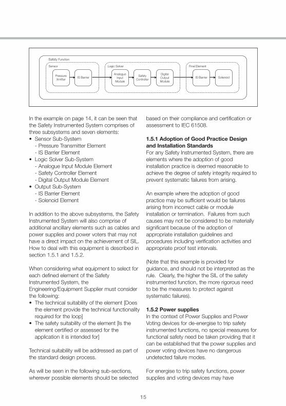
In the example on page 14, it can be seen thatthe Safety Instrumented System comprises ofthree subsystems and seven elements:• Sensor Sub-System
- Pressure Transmitter Element- IS Barrier Element
• Logic Solver Sub-System- Analogue Input Module Element- Safety Controller Element- Digital Output Module Element
• Output Sub-System- IS Barrier Element- Solenoid Element
In addition to the above subsystems, the SafetyInstrumented System will also comprise ofadditional ancillary elements such as cables andpower supplies and power voters that may nothave a direct impact on the achievement of SIL.How to deal with this equipment is described insection 1.5.1 and 1.5.2.
When considering what equipment to select foreach defined element of the SafetyInstrumented System, theEngineering/Equipment Supplier must considerthe following:• The technical suitability of the element [Does
the element provide the technical functionalityrequired for the loop]
• The safety suitability of the element [Is theelement certified or assessed for theapplication it is intended for]
Technical suitability will be addressed as part ofthe standard design process.
As will be seen in the following sub-sections,wherever possible elements should be selected
based on their compliance and certification orassessment to IEC 61508.
1.5.1 Adoption of Good Practice Designand Installation StandardsFor any Safety Instrumented System, there areelements where the adoption of goodinstallation practice is deemed reasonable toachieve the degree of safety integrity required toprevent systematic failures from arising.
An example where the adoption of goodpractice may be sufficient would be failuresarising from incorrect cable or moduleinstallation or termination. Failures from suchcauses may not be considered to be materiallysignificant because of the adoption ofappropriate installation guidelines andprocedures including verification activities andappropriate proof test intervals.
(Note that this example is provided forguidance, and should not be interpreted as therule. Clearly, the higher the SIL of the safetyinstrumented function, the more rigorous needto be the measures to protect againstsystematic failures).
1.5.2 Power suppliesIn the context of Power Supplies and PowerVoting devices for de-energise to trip safetyinstrumented functions, no special measures forfunctional safety need be taken providing that itcan be established that the power supplies andpower voting devices have no dangerousundetected failure modes.
For energise to trip safety functions, powersupplies and voting devices may have

16
1.5 DESIGN AND ENGINEERING
dangerous undetected failure modes, andtherefore will require consideration during SIL Achievement.
Whether an element of a safety instrumentedfunction is considered during SIL Achievementor not is of course dependant upon the safetyinstrumented function itself and each must beassessed individually. Wherever an element isexcluded from SIL Achievement, the rationalefor this exclusion must be clearly stated.
1.5.3 Suitability of Safety ElementsBefore selecting elements for a safety system, it is first important to understand what safetyrelated data is required. In order todemonstrate compliance to IEC 61508 in termsof SIL Capability, each element should have thefollowing information available:• Safe Failure Fraction (SFF)• Hardware Fault Tolerance (HFT)• Type Classification• Target Failure Measure, expressed as either:
- Pfdavg, or- Dangerous Failure Rate [hour-]
• Systematic Capability
The objective of gathering the data above foreach element of the logic solver is to enable SILAchievement for the end to end safety functionto be performed.
Consideration must be given to the availabilityand supportive evidence of these parametersfor each element when selecting those elementson the basis of their functional safety suitability.
In the case of elements being supplied from athird party, a validated claim that the elementssupplied have the claimed parameters. In theabsence of a validated (validated by either anaccredited certification body, or independentassessor) claim of any of these parameters fromthe supplier of the equipment, this should bedeclared as ‘Not Available’ in the SILAchievement Report.
Sound judgment should be used in theselection of equipment without substantiateddata – Demonstration of SIL Achievement for asafety function could be considered ineffective ifelements are selected that have no availabledata, the question would be asked as to whythe element was selected in the first place!
Note that care should be taken when selectingelements as to their Type classification (i.e. TypeA or Type B; see IEC 61508-2 clauses 7.4.3.1.2and 7.4.3.1.3). Type A and Type B subsystems(or elements) are described below:
• Type A: A device (subsystem/element) can be regarded as a Type ‘A’ device, if, for the components required to achieve the safety function:- the failure modes of all constituent
components are well defined; and- the behaviour of the subsystem under
fault conditions can be completelydetermined; and
- there is sufficient dependable failure datafrom field experience to show that theclaimed rates of failure for detected andundetected dangerous failures are met
• Type B: A device (subsystem/element) can be regarded as a Type ‘B’ device, if, for the components required to achieve the safety function:- the failure mode of at least one constituent
component is not well defined; or- the behaviour of the subsystem under fault
conditions cannot be completelydetermined; or
- there is insufficient dependable failure datafrom field experience to support claims forrates of failure for detected and undetecteddangerous failures
An elements compliance to, and certification orassessment against IEC 61508, should clearlyhave identified the type classification.

17
1.5.4 Legacy StandardsShould the element certification statecompliance to DIN V 19250 (or DIN19250/19251) and DIN V VDE 0801 then thecertification will have been based on the safetycategories of DIN 19250/19251and the safetyrequirements of DIN V VDE 0801.
The safety categories relating to these legacystandards are based on classification to AKclasses (AK1-AK8) and as such no linkage ofthese safety categories can be made toquantified target failure measures (as exists inIEC 61508). Any linkages to SIL’s (based onIEC 61508) are based on pragmatic judgments.Therefore, systems which have safetycategories classified to DIN V 19250/19251 and designed to DIN V VDE 0801 cannot beclaimed to be designed to IEC 61508 (even though there may be statements that a particular AK Class is equivalent to a specific SIL).
Where a certificate states compliance to DIN V19250 (or DIN 19250/19251) and DIN V VDE0801, the Safe Failure Fraction, Hardware FaultTolerance and Systematic Capability may not beavailable. Compliance with those standards, inrespect of the specified AK classes, provides asystematic capability determined by thespecified AK class, and not IEC 61508.
1.5.5 Determination of Parameters fromFirst PrinciplesWhere no substantiated data (refer to section1.5.3), either offering compliance with IEC61508 or legacy standards such as DIN V19250 (or DIN 19250/19251) and DIN V VDE0801, determination of the key parametersrequired from first principles will be required.
This process requires very specific technicalcompetency, and should only be attempted bythe appropriate, qualified organisations and/orindividuals.
For each identified element the following shallbe determined:i. The failure modes (in terms of the behaviour
of its outputs) due to random hardwarefailures that result in a failure of the safetyfunction that are not detected by diagnosticsinternal to the element.
ii. The estimated failure rate for every failuremode in (i).
iii. The failure modes (in terms of the behaviourof its outputs) due to random hardwarefailures that results in a failure of the safetyfunction that are detected by diagnosticsinternal to the element.
iv. The estimated failure rate for every failuremode in (iii).
v. The diagnostic test interval for every failuremode in (iii) that is detected by diagnosticsinternal to the element.
vi. The relevant part of the element thatsupports the function that is Type “A” andthe relevant part of the element thatsupports the function that is Type “B”.
For further guidance, refer to IEC 61508-2;clause 7.4.3.1.2 and 7.4.3.1.3.

18
1.6 DEMONSTRATING SIL ACHIEVEMENT
As part of the design process, the SafetyInstrumented System has been deconstructedinto Sub-Systems and Elements. For each ofthose elements, parameters relating to theirsuitability in terms of functional safety have been collected.
The next step in the process of SILAchievement is to collate this information, andpresent the evidence necessary to substantiatethe claim that the safety functions described inthe safety requirements specification, achievetheir target SIL.
The evidence should be presented in the formof a SIL Achievement Report, which provides,for each safety function, the following:(1) The Hardware Safety Integrity for the safety
function achieved (in the form of the Pfdavgor dangerous failure rate (hour) and HFT (forthe specified SFF)); and,
(2) The Systematic Safety Integrity for thesafety function achieved (in the form of theSystematic Capability for a subsystem/element) including references to anyappropriate Techniques and Methods adopted.
(3) Confirmation, that the targets for (1) and (2),specified in the Safety RequirementsSpecification, have been met or if thetargets have not been met, the reasons.
Note: In respect of (2) above, Systematic SafetyIntegrity, the Systematic Capability may beclaimed using evidence of proven in use.However, using this approach is stronglydiscouraged, based on the following difficulties:
• Evidence will be required as to how the datawas collected – many end users may simplydiscard faulty equipment, and replace with aspares holding, instead of returning to themanufacturer.
• Evidence will be required as to theenvironment the equipment was used in – aproven in use claim can only be made fordevices used in the in the same way, forexample the process environment.
• Evidence will be required to substantiate thesample size – how many samples need tohave been taken before the proven in useclaim can be deemed as valid?
• Complexities in the supply chain may meanthat accurate records are difficult to obtain –for example, the supplier of the device maynot be the manufacturer of the device. Themanufacturer of the device may appointcertified repairers.
Note that the concept of “proven in use" issolely related to systematic concepts; it hasnothing to do with random hardware failures.The process of demonstrating SIL is describedin the following sub-sections. Where examplesare provided, these are based on the highpressure trip discussed in section 1.4, for easeof reference, this is shown again below:
Safety Function
Sensor
PressureXmitter
IS Barrier
Logic Solver
AnalogueInput
Module
SafetyController
DigitalOutputModule
Final Element
IS Barrier Solenoid
19
Note that all quantitative and qualitative dataquoted in the examples do not relate to aspecific product or range of products.
1.6.1 Identification of Generic FunctionsSIL Achievement is required to bedemonstrated for each safety function; howeverthe concept of ‘generic’ functions may beidentified, based on the following rationale:Where it is established that the route taken frominput subsystem to output subsystem, inimplementing the safety function, takes thesame route then this can be defined as ageneric function. In this situation it would beacceptable to provide the evidence of SILAchievement only once for this generic function.This is based on the assumption that all thosesafety functions, that are to be regarded asgeneric, have associated with them identicaldangerous modes of failure and identical safemodes of failure. If this is not the case then theconcept of a generic function is not valid.When generic safety functions are identified,and adopted in demonstrating SILAchievement, it is critical that the individualsafety functions associated with that generic type are clearly identified and listed.
1.6.2 Demonstration of Achieved HardwareSafety IntegrityThe requirements for Hardware Safety Integritycomprise of:• The Architectural Constraints expressed as a
Safe Failure Fraction (SFF) and a HardwareFault Tolerance (HFT)
• The Pfdavg or dangerous failure rate relating to dangerous random hardware failures
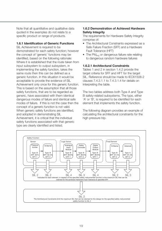
1.6.2.1 Architectural ConstraintsTables 1 and 2 in section 1.4.2 provide thetarget criteria for SFF and HFT for the targetSIL. Reference should be made to IEC61508-2clauses 7.4.3.1.1 to 7.4.3.1.4 for details oninterpreting the table.
The two tables address both Type A and TypeB safety-related subsystems. The type, either‘A’ or ‘B’, is required to be identified for eachelement that implements the safety function.
The following diagram provides an example ofcalculating the architectural constraints for thehigh pressure trip.
Safety Function
Sensor
PressureXmitter
Type: BSFF: 82%
HFT: 1
Type: BSFF: 92.5%
HFT: 0
Type: BSFF: 99.9%
HFT: 1
Type: BSFF: 99.9%
HFT: 0
Type: BSFF: 99.9%
HFT: 1
Type: BSFF: 97.4%
HFT: 0
Type: ASFF: 91.4%
HFT: 0
IS Barrier AnalogueInput
Module
SafetyController
DigitalOutputModule
IS Barrier Solenoid
Logic Solver Final Element
SIL 2 SIL 2 SIL 4 SIL 3
SIL 2
SIL 4 SIL 2 SIL 3Indicated for each element, in respect of the specified safety instrumented function is the maximum SIL that can be
claimed for the achieved Hardware Fault Tolerance & specified SFF
The Architectural Constraints limit the maximum SIL that can be claimed for the design for the specified safety instrumentedsafety function to SIL 2

20
1.6 DEMONSTRATING SIL ACHIEVEMENT
As can be seen from the example above, thearchitectural constraint has been calculated foreach element of the safety function. Thearchitectural constraint is limited by the lowestachieved SIL (in terms of architecturalconstraint), the Final Element IS Barrier, which islimited to SIL 2.
The maximum claimed SIL, in terms ofarchitectural constraint, for the function is SIL 2.
1.6.2.2 Quantification of DangerousRandom Hardware FailuresTarget Failure Measure is expressed as theProbability of failure on demand (Pfd) orProbability of failure per hour (Pfh)/dangerousfailure rate per hour. The target failure measure,as a basis for determining the measures to be
taken to achieve the required safety integrity, isdependent upon whether the safetyinstrumented function is considered to beoperating in low demand (Pfd is used) or highdemand mode of operation (Pfh/dangerousfailure rate per hour is used).
Referring to section 1.4.2, Tables 1 and 2provide the target criteria for the target failuremeasure for the target SIL. Reference shouldbe made to IEC61508-1 clause 7.6.2.9 fordetails on interpreting the tables. Each element,with respect to the specified safety function, isassessed independently.
The following diagram provides an example ofcalculating the target failure measure for thehigh pressure trip.
Safety Function
Sensor
PressureXmitter
Pfd6.1x10-2
Pfd3.17x10-4
Pfd2.25x10-5
Pfd2.93x10-5
Pfd2.64x10-5
Pfd2.44x10-5
Pfd3.0x10-2
IS Barrier AnalogueInput
Module
SafetyController
DigitalOutputModule
IS Barrier Solenoid
Logic Solver Final Element
SIL 1 band 6.1x10⁻² + + + + + +
SIL 3 band 3.17x10⁻⁴
SIL 4 band 2.25x10⁻⁵
SIL 4 band 2.93x10⁻⁵
SIL 1 band 9.14x10⁻²
SIL 4 band 2.64x10⁻⁵
SIL 4 band 2.44x10⁻⁵
SIL 1 band 3.0x10⁻²
Achieved target failure measure for each element (Assuming Low Demand Mode of Operation)
The maximum claimed SIL for the safety instrumented function, in respect of the dangerous random hardware failures, is in the SIL 1 band

21
As can be seen from the example on page 20,the target failure measure has been calculatedfor each element of the safety function. In thecalculation, a low demand mode has beenassumed, and it is also assumed that the proof test interval for each element is greaterthan the required minimum proof test intervalrequired by the function.
Evaluating the total target failure measureachieved is obtained by summation of the Pfdavg values for each subsystem.
For more elaborate configurations, for examplethose that include voted sensor subsystemsand which have redundant channels, it wouldbe necessary, in determining the total targetfailure measure for the Safety InstrumentedSystem, to take into account common cause failures.
For further information, and examples of morecomplex target failure measure calculations,refer to IEC61508-6 (Annex B).
The maximum claimed SIL, in terms of targetfailure measure, for the safety instrumentedfunction is in the SIL 1 band.
1.6.3 Demonstration of AchievedSystematic Safety IntegritySystematic Safety Integrity cannot, in general,be quantified and is based on qualitativerequirements and tables of specified techniquesand measures in IEC61508. Assessment ofsystematic safety integrity utilises IEC61508,Part 7 Overview of techniques and measures:Annex B and Annex C.
It is necessary for each element involved in theimplementation of the specified safety functionto meet the systematic safety integrityrequirements of the SIL of the safety function.In addition, it is also necessary to ensure thatthe integration activities and processes for all of the elements of the safety function areachieved in compliance with the requirements of IEC 61508 to ensure that the integration process itself does not lead to unacceptablesystematic failures.
To this end, all organisations responsible in thePre-Design and Design and Installation activitiesshould provide evidence that the safety systemhas been developed under a functional safetymanagement system, and the integration of theelements, relevant to the specified safetyfunctions, have been performed using suitabletechniques and methods. Further informationcan be found in the chapter ‘A methodology forachieving organisational functional safetycertification to IEC61508’ of this handbook.The following diagram provides an example ofcalculating the systematic capability for the highpressure trip.
22
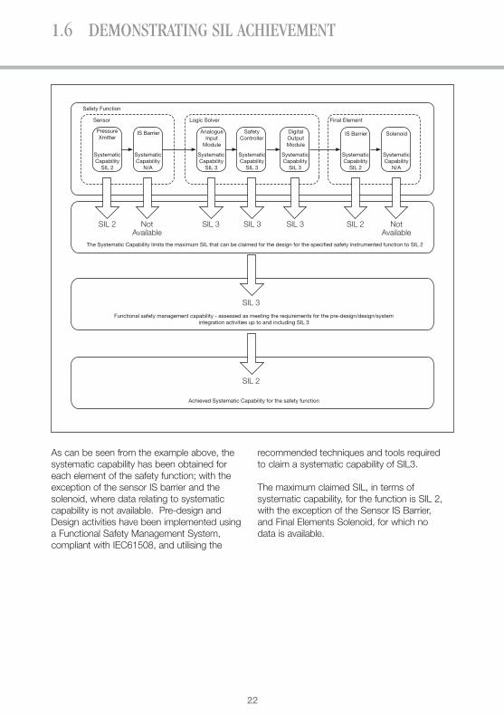
1.6 DEMONSTRATING SIL ACHIEVEMENT
Safety Function
Sensor
PressureXmitter
SystematicCapability
SIL 2
SystematicCapability
N/A
SystematicCapability
SIL 3
SystematicCapability
SIL 3
SystematicCapability
SIL 3
SystematicCapability
SIL 2
SystematicCapability
N/A
IS Barrier AnalogueInput
Module
SafetyController
DigitalOutputModule
IS Barrier Solenoid
Logic Solver Final Element
SIL 2 NotAvailable
SIL 3 SIL 3
SIL 3
SIL 3 SIL 2 NotAvailable
The Systematic Capability limits the maximum SIL that can be claimed for the design for the specified safety instrumented function to SIL 2
Functional safety management capability - assessed as meeting the requirements for the pre-design/design/systemintegration activities up to and including SIL 3
SIL 2
Achieved Systematic Capability for the safety function
As can be seen from the example above, thesystematic capability has been obtained foreach element of the safety function; with theexception of the sensor IS barrier and thesolenoid, where data relating to systematiccapability is not available. Pre-design andDesign activities have been implemented usinga Functional Safety Management System,compliant with IEC61508, and utilising the
recommended techniques and tools required to claim a systematic capability of SIL3.
The maximum claimed SIL, in terms ofsystematic capability, for the function is SIL 2,with the exception of the Sensor IS Barrier, and Final Elements Solenoid, for which no data is available.

23
1.6.4 SIL Achievement SummaryIn the previous sections, a worked example of SIL Achievement has been shown for asimple safety instrumented function, a highpressure trip. A summary of the SILAchievement exercise, for this high pressure trip is given below.
Safety Instrumented Function: ‘In order to prevent the rupture of pressure tankVS-01, Valve V-01-01 must be opened within 2seconds, when the pressure in vessel VS-01rises to 2.6 bar’
Target: SIL 1
Mode: Low Demand
Summary of SIL achievement• In terms of Architectural Constraint,
SIL 2 is achieved• In terms of the dangerous random
hardware failures, the Pfdavg achieved is in the SIL 1 band
• In terms of systematic safety integrity, SIL 2 is achieved with the exception of theSensor IS Barrier, and Final ElementSolenoid, for which no data is available
On this basis, the achieved SIL for the highPressure Trip can be said to be SIL 1, with the exception of the systematic capabilityof the sensor IS barrier and final elementsolenoid, for which no data is available.

24
1.7 SUMMARY
In summarising the methodology for theachievement of a target SIL, it is important toconsider the following key points:
1. SIL Achievement relates to the ability of thedesigned Safety Instrumented System (SIS)to carry out the specified safety instrumentedfunction to the required SIL.
Achievement of a target SIL is based onindividual safety instrumented functions (orgeneric safety instrumented functions). Thisis an important concept, as without having aclear definition of each safety instrumentedfunction, and a target SIL for each of thosesafety instrumented functions, SILAchievement becomes an impossible task.
It is also important to understand that theconcept of a ‘SIL x Safety InstrumentedSystem’ is not correct, as SIL applies tosafety instrumented functions that are part ofa Safety Instrumented System. Elements ofthat Safety Instrumented System are requiredto be suitable for use in carrying out a SIL xsafety function. Safety System RequirementsSpecifications need to avoid simply stating‘Supply a SIL x Safety System’.
2. Demonstration of SIL Achievement is not justabout Pfdavg.
Producing a reliability and availability reportfor a Safety Instrumented System is notdemonstrating that the target SIL has beenmet for each safety instrumented function.SIL Achievement is a far more complexprocess, involving Architectural Constraint,and Systematic Capability, as well as thePfdavg. Also remember that Pfdavg is not asuitable failure measure for a highdemand/continuous mode of operation.
Systematic Capability must also beconsidered during the design and engineeringphase. Just because individual elementsused to carry out the safety instrumentedfunction are certified for use, does not mean
that when those elements are boughttogether and configured that therequirements of the safety instrumentedfunction have been achieved in the design ofthe Safety Instrumented System. Theconfiguration of the Safety InstrumentedSystem will have an impact on theSystematic Capability achieved00. Theintegration and configuration of the safetyinstrumented function should also followrecognised techniques and methods asdescribed in IEC 61508 to ensure systematiccapability is achieved.
3. The importance of a good safetyrequirements specification.
Without a good Safety RequirementsSpecification, the information necessary forthe demonstration of SIL achievement maynot be available. Apart from the obviousneed to identify individual safety instrumentedfunctions and their target SIL, identifying themode of operation and proof testrequirements are also necessary in order todemonstrate SIL Achievement.
4. The importance of equipment selection.
Once safety instrumented functions and theirtarget SIL have been identified, it is criticalthat the correct elements are specified whichwill implement each safety instrumentedfunction. Incorrect specification of theseelements may mean that the target SIL isunachievable – impacting not only functionalsafety but also schedule and cost. For theEngineering/Equipment Supplier it isimportant to ensure that the correctequipment is identified during the proposaland initial design phases of the project – ofcourse this process requires a good SafetyRequirements Specification from the EndUser/Operator.

25
What of the future? It is clear that education isan important factor. Each organisation shouldclearly understand their position, andresponsibilities in the supply chain. Specifically:
1. Equipment suppliers should begin to providecomprehensive and complete data for theirproducts – Hardware Fault Tolerance, SafeFailure Fraction, Target Failure Measure,device type and systematic capability.Agreement should be sought by equipmentmanufacturers, as to how best to present thisdata, guided by the requirements of endusers and system integrators.
2. All members of the supply chain shouldconsider implementing comprehensivefunctional safety management systems.Certification of an organisations functionalsafety management system by third partiesprovides evidence to others in the supplychain that functional safety and thussystematic capability of that organisation canbe demonstrated and substantiated.
Finally, Industry in general should begin tounderstand that SIL is a characteristic of theSafety Instrumented Function, not the SafetyInstrumented System, and the demonstration ofSIL is not just about Pfdavg!

26
REFERENCES
IEC 61508 Functional safety of electrical/electronic/programmable electronic safety-related systems
IEC 61511 Functional safety – Safety instrumented systems for the process industry sector
DIN V 19250 Fundamental safety aspects for measurements and control equipment
DIN V VDE 0801 Principles for computers in safety related systems

27
ABOUT THE AUTHOR
Peter previously worked forABB in the UK, managingthe Safety AutomationTeam, and providingconsultancy servicesthrough ABB’s Safety LeadCompetency Centre (SLCC)to Customers and other
ABB divisions. Now appointed Process Safety Programme Manager for the UKPetroleum Industry Association Ltd, Peter has over 20 years’ experience in the field of automation including the deign andengineering of automated control systems for the nuclear, pharmaceutical and Oil and Gas Industries.
Peter Davidson MIET, MInstMC

ABB LimitedHoward RoadEaton SoconSt NeotsCambridgeshirePE19 8EUTel: 01480 475321Fax: 01480 217948www.abb.com
© Copyright 2009 ABB. All rights reserved.Specifications subject to change without notice.
AM
etho
dolo
gyfo
rth
eac
hiev
emen
tof
targ
etS
IL/M
arch
09