a method for storing semiconductor test data to simplify
TRANSCRIPT

A Method for Storing Semiconductor Test Datato Simplify Data Analysis
Jeremy W. WebbJ. Webb Consulting
Woodland, California 95695
Abstract—The automated testing of semiconductor wafers,integrated circuits (IC), and surface mount devices generatesa large volume of data. These devices are tested in stages andtheir test data is typically collected in log files, spreadsheets,and comma separated value files that are stored at both thefoundry and on-site on file shares. Building a cohesive pictureof the quality and performance of these devices can be difficultsince the data is scattered throughout many files. In addition,tracking any deviations in performance from wafer to wafer byanalyzing historical process control monitoring (PCM) test datais a manual, laborious task. Collecting the test data from multiplesources (e.g., foundries and contract manufacturers) can becumbersome when manual intervention is required. Automatingthe transfer of test data from third party servers to on-site fileshares is crucial to providing a consistent method of accessingthe data for analysis. This paper provides a method of bothimplementing a database for storing test data collected at thevarious stages of IC manufacturing, as well as automating theretrieval and import of test data into the database from allrelevant sources.
I. INTRODUCTION
A large volume of data is generated during semiconductor
fabrication, wafer testing, and package testing. This data can
be stored in the following file types:
• GDSII files
• Foundry process control monitor data
• Test executive software output files
• Touchstone files (e.g., S-Parameters)
The GDSII files are mainly used to extract the die names and
X/Y coordinates within a reticle for conversion into wafer level
X/Y coordinates. In the case of foundry PCM data, a single file
may be generated, which could be in the form of a spreadsheet
or a physical piece of paper. The test executive output files may
either be separated into individual files per die or all lumped
into a single spreadsheet. When using individual files per die
there can be thousands upon thousands of individual files
containing both parametric and swept data, such as touchstone
S-Parameter files.
Extracting any useful information from this collection of
files can be challenging. Often custom scripts, Excel spread-
sheets, R scripts, and GNU Plot scripts are employed to try and
make sense of the data to determine yield for individual wafers
or wafer lots, wafer-to-wafer performance, or even to generate
a pick list of good parts to be used during the packaged IC
production process.
This paper describes the steps necessary to develop a
parametric database for storing semiconductor test data. These
steps include identifying producers and consumers of data,
understanding all file formats used for storing the data, locat-
ing the directories where the data is stored, developing the
database structure, and finally automating report generation
and providing a method of accessing the data for analysis.
II. PARAMETRIC DATABASE
A. Data Producers and Consumers
Before a database can be implemented, both the producers
and consumers of data must be identified and interviewed to
understand the type of data being manipulated. In this case,
the main goal of the parametric database development was to
identify all sources of data from the start of the IC design to
production of the wafers and surface mount devices.
An interesting occurrence during the development of the
parametric database was that producers and consumers some-
times gave limited answers to initial interview questions and
it became necessary that more focused questions be asked for
further clarification. This additional probing made it possible
to learn more about the data and processes, and slowly the
full picture emerged regarding how the data was generated or
used and how it influenced the next stage of the design or
manufacturing process.
1) Producers:
Common producers of data include IC design engineers, wafer
foundries, and test executive software. The data generated by
producers will lay the foundation for the tables in the database.
Data producers have a deep understanding of the data they
generate, but they are sometimes unable to visualize the bigger
picture of how the data is connected.
a) Interview Questions:
• What type of data do you generate?
• Where do you store your data files?
• What are the stages of the production process?
• How many process stages exist for each type of device
(e.g., wafers, ICs, multi-chip modules)?
• Do you typically re-test a device during production? If so,
how do you tag the data to distinguish between previous
tests?
• What type of specifications exist for devices?
• How do you keep track of specification revisions?
978-1-5090-0790-5/16/$31.00 ©2016 IEEE

• Do you ever manually record data on paper or in a
spreadsheet?
2) Consumers:
Consumers of data include test engineers, quality engineers,
managers, production planners, and IC design engineers. Con-
sumers generally have knowledge about how to analyze the
data and an understanding of how all of the data is connected.
a) Interview Questions:
• What type of data do you access to do your job?
• Where do you access data (e.g., Foundry file transfer
protocol (FTP) server, networked file share)?
• If you connect to an FTP site, what are the credentials
used to gain access? Is the password changed at a regular
interval?
• Do you have to reformat data prior to analysis?
• What programs do you use to analyze data?
• Do you generate reports? If so, how are they formatted,
what is the purpose, who is the intended audience?
B. Data Sources
The next phase of parametric database development is often
referred to as the extract, transform, and load (ETL) phase.
This section addresses the extract and transform steps for the
development of parsing scripts, and the following section will
discuss the load steps.
Understanding the file formats used to store data is key to
determining how many parsers need to be developed. When
developing the parsing scripts, it is recommended to choose
an output format that is common to all parsers. For example,
the extensible markup language (XML) file format.
1) Design Data:
As either multi-chip or production wafers are completed and
the reticle map documentation layer has been generated, then
the GDSII file can be processed to extract a list of devices
under test (DUT) with the corresponding chip name, width
and area, and the origin positions (row/column) on the reticle
for each DUT with its corresponding x and y position. The
DUT chip name describes what type of devices are present on
the reticle. The reticle is tiled to create a wafer mask, which
in turn is used by the foundry to fabricate individual wafers.
Due to the complexity of parsing the GDSII files, this task is
often an iterative process and close collaboration is required
between the test team and the IC design team to ensure that
the proper information is present in the GDSII documentation
layer.
The overall wafer X/Y coordinates are calculated along with
the die serial labels or chip identifiers (IDs) (e.g., A5500) using
the wafer and reticle dimensions, DUT X/Y coordinates, and
other miscellaneous information. The chip IDs will be used to
associate data in the parametric database to a specific wafer
mask, wafer lot, and wafer number. The chip IDs located on
the edge of the wafer should not be tested, and can either be
tagged as being on the wafer edge at the time of GDSII data
extraction or after the GDSII data has been loaded into the
parametric database. Figure 1 shows the processing steps for
extracting, transforming, and loading the GDSII file data into
the parametric database. Listing 1 shows an example of an
XML file containing information extracted from a GDSII file
for a wafer mask.
Doc Layer Export
Chip Name, Wafer Information, Edge, chip IDs,and X/Y coordinates to XML
Chip IDs List
Fig. 1. Wafer mask GDSII file processing steps.
2) Foundry Data:
Semiconductor foundries generate a variety of data files
during the fabrication and testing process, including open
purchase orders, work in progress (WIP) status, PCM data, and
wafer test data. This data is typically stored in either comma
separated value (CSV) files or Excel spreadsheets. Figure 2
shows the processing steps for extracting, transforming, and
loading the foundry open purchase order and WIP data into
the parametric database.
Open POs and WIP
Open POs WIP
Fig. 2. Wafer fabrication work in progress and open purchase order dataprocessing steps.
When starting a new relationship with a foundry, the format-
ting of the files can vary, but after two or three runs through
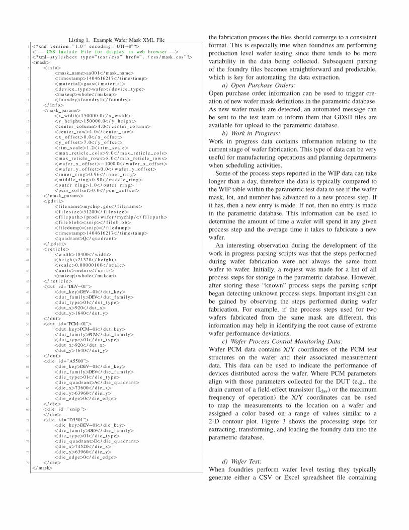
Listing 1. Example Wafer Mask XML File1 <? xml v e r s i o n =” 1 . 0 ” e n c o d i n g =”UTF−8” ?><!−− CSS I n c l u d e F i l e f o r d i s p l a y i n web browse r −−>
3 <? xml−s t y l e s h e e t t y p e =” t e x t / c s s ” h r e f =” . . / c s s / mask . c s s ” ?><mask>
5 <i n f o><mask name>aa001</ mask name>
7 <t imes t amp>1404616217</ t imes t amp><m a t e r i a l>g a a s</ m a t e r i a l>
9 <d e v i c e t y p e>wafe r</ d e v i c e t y p e><makeup>whole</ makeup>
11 <f o u n d r y>f o u n d r y 1</ f o u n d r y></ i n f o>
13 <mask params><x wid th>150000 .0</ x wid th>
15 <y h e i g h t>150000 .0</ y h e i g h t><c e n t e r c o l u m n>4 . 0</ c e n t e r c o l u m n>
17 <c e n t e r r o w>4 . 0</ c e n t e r r o w><x o f f s e t>0 . 0</ x o f f s e t>
19 <y o f f s e t>7 . 0</ y o f f s e t><r i m s c a l e>1 . 2</ r i m s c a l e>
21 <m a x r e t i c l e c o l s>9 . 0</ m a x r e t i c l e c o l s><m a x r e t i c l e r o w s>8 . 0</ m a x r e t i c l e r o w s>
23 <w a f e r x o f f s e t>−1000.0</ w a f e r x o f f s e t><w a f e r y o f f s e t>0 . 0</ w a f e r y o f f s e t>
25 <i n n e r r i n g>0 . 9 6</ i n n e r r i n g><m i d d l e r i n g>0 . 9 8</ m i d d l e r i n g>
27 <o u t e r r i n g>1 . 0</ o u t e r r i n g><p c m x o f f s e t>0 . 0</ p c m x o f f s e t>
29 </ mask params><g d s i i>
31 <f i l e n a m e>mychip . gds</ f i l e n a m e>< f i l e s i z e>51200</ f i l e s i z e>
33 <f i l e p a t h>/ p rod / wafe r / mychip /</ f i l e p a t h><f i l e b l o b><s n i p></ f i l e b l o b>
35 <f i l e d u m p><s n i p></ f i l e d u m p><t imes t amp>1404616217</ t imes t amp>
37 <q u a d r a n t>Q</ q u a d r a n t></ g d s i i>
39 < r e t i c l e><wid th>18400</ w id th>
41 <h e i g h t>21320</ h e i g h t><s c a l e>0 .00000100</ s c a l e>
43 <u n i t s>m e t e r s</ u n i t s><makeup>whole</ makeup>
45 </ r e t i c l e><d u t i d =”DEV−01”>
47 <du t key>DEV−01</ du t key><d u t f a m i l y>DEV</ d u t f a m i l y>
49 <d u t t y p e>01</ d u t t y p e><du t x>920</ du t x>
51 <du t y>1640</ du t y></ d u t>
53 <d u t i d =”PCM−01”><du t key>PCM−01</ du t key>
55 <d u t f a m i l y>PCM</ d u t f a m i l y><d u t t y p e>01</ d u t t y p e>
57 <du t x>920</ du t x><du t y>1640</ du t y>
59 </ d u t><d i e i d =”A5500 ”>
61 <d i e k e y>DEV−01</ d i e k e y><d i e f a m i l y>DEV</ d i e f a m i l y>
63 <d i e t y p e>01</ d i e t y p e><d i e q u a d r a n t>A</ d i e q u a d r a n t>
65 <d i e x>73600</ d i e x><d i e y>63960</ d i e y>
67 <d i e e d g e>0</ d i e e d g e></ d i e>
69 <d i e i d =” s n i p ”></ d i e>
71 <d i e i d =”D5501 ”><d i e k e y>DEV−01</ d i e k e y>
73 <d i e f a m i l y>DEV</ d i e f a m i l y><d i e t y p e>01</ d i e t y p e>
75 <d i e q u a d r a n t>D</ d i e q u a d r a n t><d i e x>74520</ d i e x>
77 <d i e y>63960</ d i e y><d i e e d g e>0</ d i e e d g e>
79 </ d i e></ mask>
the fabrication process the files should converge to a consistent
format. This is especially true when foundries are performing
production level wafer testing since there tends to be more
variability in the data being collected. Subsequent parsing
of the foundry files becomes straightforward and predictable,
which is key for automating the data extraction.
a) Open Purchase Orders:
Open purchase order information can be used to trigger cre-
ation of new wafer mask definitions in the parametric database.
As new wafer masks are detected, an automated message can
be sent to the test team to inform them that GDSII files are
available for upload to the parametric database.
b) Work in Progress:
Work in progress data contains information relating to the
current stage of wafer fabrication. This type of data can be very
useful for manufacturing operations and planning departments
when scheduling activities.
Some of the process steps reported in the WIP data can take
longer than a day, therefore the data is typically compared to
the WIP table within the parametric test data to see if the wafer
mask, lot, and number has advanced to a new process step. If
it has, then a new entry is made. If not, then no entry is made
in the parametric database. This information can be used to
determine the amount of time a wafer will spend in any given
process step and the average time it takes to fabricate a new
wafer.
An interesting observation during the development of the
work in progress parsing scripts was that the steps performed
during wafer fabrication were not always the same from
wafer to wafer. Initially, a request was made for a list of all
process steps for storage in the parametric database. However,
after storing these “known” process steps the parsing script
began detecting unknown process steps. Important insight can
be gained by observing the steps performed during wafer
fabrication. For example, if the process steps used for two
wafers fabricated from the same mask are different, this
information may help in identifying the root cause of extreme
wafer performance deviations.
c) Wafer Process Control Monitoring Data:
Wafer PCM data contains X/Y coordinates of the PCM test
structures on the wafer and their associated measurement
data. This data can be used to indicate the performance of
devices distributed across the wafer. Where PCM parameters
align with those parameters collected for the DUT (e.g., the
drain current of a field-effect transistor (Idss) or the maximum
frequency of operation) the X/Y coordinates can be used
to map the measurements to the location on a wafer and
assigned a color based on a range of values similar to a
2-D contour plot. Figure 3 shows the processing steps for
extracting, transforming, and loading the foundry data into the
parametric database.
d) Wafer Test:
When foundries perform wafer level testing they typically
generate either a CSV or Excel spreadsheet file containing

Summary Data
Wafer Mask Lot Number
RF Raw DataPCM4 Data
Fig. 3. Wafer fabrication process control monitoring data processing steps.
test data for all die on the wafer. It is recommended to
have the foundry include the specifications for each parameter
measured in the data file, as well as the conditions for the
measurement. For example, how a specific DUT was biased
for the measurement. Tracking revisions made to specifications
can be useful when the yield of a wafer changes or a new trend
occurs regarding a specific parameter or set of parameters.
Generally, the more information a foundry can include in the
header of the test data file the better because it reduces the
number of descriptors needed by a script when importing into
the parametric database. The following is a sample list of
information that should be included in the header of the data
file:
• Wafer mask name
• Wafer lot number or identifier
• Wafer number
• Test station identifier
• Test date and time
• Measurement conditions
If the measurement data for each DUT is provided its own
file, then the DUT or chip name should be included in the
header as well.
3) Production Data:
New product introduction (NPI) and production tests generate
a significant number of data files, including parametric test
data files and swept data measurement files. For wafer testing,
the test executive software is usually controlling a wafer probe
station using the DUT X/Y coordinates to identify the probing
location on the wafer. Depending on the makeup of the wafer
(e.g., multi-chip wafer (MCW) or production wafer), the test
executive software will either test the entire wafer in one
pass or perform multiple passes per unique DUT type. In the
case of an MCW, multiple test and measurement equipment
setups may be required in addition to an adjustment of the die
probe configuration, which adds more variance to the type of
data being collected. The test executive software will either
generate a combined set of data in a single file or individual
data files for each unique DUT. It can be convenient to use
a combined data file for production wafers containing only
a single type of DUT. However, most wafer tests do not
complete successfully in one pass, and using a single data
file can be difficult to keep up to date after the overall wafer
tests have been completed. Generating a separate data file per
device may end up being more efficient for post-processing
tasks. Additionally, when processing a batch of data files
using the parsing script, separate data files can allow for
quicker recovery when restarting the parsing script after an
error occurs during the parsing (e.g., server power loss or disk
failure). Figure 4 shows the processing steps for extracting,
transforming, and loading the parametric test data files and
swept data measurement files into the parametric database.
Test DUTs and stores parametric data and touchstone files.
Parametric data and touchstone file data export to XML.
DUT parametric data and touchstone file data.
Fig. 4. Wafer parametric test data and swept data measurement file processingsteps.
The format of the data files generated by the test executive
software tends to change over time due to changes in the test
method, parameters measured and stored, updates to the file
header, or even to the personnel managing the test executive
software. The parsing scripts must be written in such a way
that they can detect the deviations in the data file formatting.
The type of deviations that can occur range from differences
in header formatting to adding entire sections for documenting
which test equipment was used to perform the measurements.
It is recommended that a file version be included in all data
files that indicates the version of the data file template. Using a
file version creates a straightforward process for detecting the
different data files in a parsing script. When uploading a large
set of historical data files it can be difficult to ascertain how
many data file variants exist in the set of files. The simplest
method is to execute a parsing script on a large set of files
and add provisioning in the parsing script to flag an error
upon detecting deviations. Depending on the severity of the

deviation, only a minor change may be required to allow the
parsing script to process the data file successfully. In the case
of major deviations, new parsing sub-routines may need to be
written as well as a sub-routine to determine which parsing
sub-routine should be executed.a) Parametric Test Data:
Listing 2 shows an example of an XML file containing
information extracted from a parametric test data file for a
unique device.
Listing 2. Example Parametric Test Data XML File<? xml v e r s i o n =” 1 . 0 ” e n c o d i n g =”UTF−8” ?>
2 <!−− CSS I n c l u d e F i l e f o r d i s p l a y i n web browse r −−><? xml−s t y l e s h e e t t y p e =” t e x t / c s s ” h r e f =” . . / c s s / d a t a . c s s ” ?>
4 <d i e d a t a><i n f o>
6 <f i l e v e r s i o n>1 . 1</ f i l e v e r s i o n><username>jwwebb</ username>
8 <t imes t amp>1404616217</ t imes t amp><mask name>aa001</ mask name>
10 <l o t n u m b e r>1</ l o t n u m b e r><w a f e r i d>1</ w a f e r i d>
12 <q u a d r a n t>q</ q u a d r a n t><d e v i c e t y p e>wafe r</ d e v i c e t y p e>
14 <m a t e r i a l>g a a s</ m a t e r i a l><d u t f a m i l y>DEV</ d u t f a m i l y>
16 <d u t t y p e>01</ d u t t y p e><d u t c h i p i d>A5500</ d u t c h i p i d>
18 <d u t s t a t u s>PASSED</ d u t s t a t u s><t e s t s e q u e n c e> f i r s t −p a s s</ t e s t s e q u e n c e>
20 <t e s t s y s t e m>TS10</ t e s t s y s t e m>
<t e s t t y p e> f i n a l t e s t</ t e s t t y p e>22 </ i n f o>
<s p e c i f i c a t i o n s>24 <s p e c c l a s s i d =”DEV−01”>
<s p e c i f i c a t i o n i d =” Ambient ”>26 <s p e c l o w v a l u e>15</ s p e c l o w v a l u e>
<s p e c h i g h v a l u e>35</ s p e c h i g h v a l u e>28 <s p e c u n i t s>degC</ s p e c u n i t s>
<s p e c d e s c>Ambient Tempera tu re</ s p e c d e s c>30 <s p e c t y p e>p a r a m e t e r</ s p e c t y p e>
</ s p e c i f i c a t i o n>32 <s p e c i f i c a t i o n i d =” I d s s ”>
<s p e c l o w v a l u e>0 . 2 2</ s p e c l o w v a l u e>34 <s p e c h i g h v a l u e>0 . 3 3</ s p e c h i g h v a l u e>
<s p e c u n i t s>Amps</ s p e c u n i t s>36 <s p e c d e s c>Dra in C u r r e n t</ s p e c d e s c>
<s p e c t y p e>p a r a m e t e r</ s p e c t y p e>38 </ s p e c i f i c a t i o n>
</ s p e c c l a s s>40 </ s p e c i f i c a t i o n s>
<measure>42 <m e a s u r e c l a s s i d =”DEV−01”>
<p a r a m e t e r i d =” Ambient Tempera tu r e ”>44 <param va lue>21 .264</ pa ram va lue>
<p a r a m u n i t s>degC</ p a r a m u n i t s>46 <param cond>Vg = 0 . 0 , Vd=8</ param cond>
<p a r a m s t a t u s>p a s s e d</ p a r a m s t a t u s>48 </ p a r a m e t e r>
<p a r a m e t e r i d =” I d s s ”>50 <param va lue>0 .2869048</ pa ram va lue>
<p a r a m u n i t s>Amps</ p a r a m u n i t s>52 <param cond>Vg = 0 . 0 , Vd=8</ param cond>
<p a r a m s t a t u s>p a s s e d</ p a r a m s t a t u s>54 </ p a r a m e t e r>
</ m e a s u r e c l a s s>56 </ measure>
</ d i e d a t a>
b) Swept Measurement Data:
In the case of swept data measurements, using a separate
file makes more sense because the measured data is typically
contained in a proprietary format. A common format for
swept network measurements containing S-Parameters is a
touchstone file. These files tend to be made up of columns
containing frequency and the individual S-Parameter measure-
ments. Storing the touchstone option string (e.g., # HZ S RI R
50) will allow future extraction of the S-Parameters from the
parametric database into a touchstone file for further analysis
using tools such as Keysight Technologies’ Advanced Design
System software. Listing 3 shows an example of an XML file
containing information extracted from a touchstone data file
for a unique device.
Listing 3. Example Touchstone Data XML File1<? xml v e r s i o n =” 1 . 0 ” e n c o d i n g =”UTF−8” ?>
<!−− CSS I n c l u d e F i l e f o r d i s p l a y i n web browse r −−>3<? xml−s t y l e s h e e t t y p e =” t e x t / c s s ” h r e f =” . . / c s s / d a t a . c s s ” ?>
<t o u c h s t o n e>5<i n f o>
<mask name>aa001</ mask name>7<username>jwwebb</ username>
<t imes t amp>1404616217</ t imes t amp>9<m a t e r i a l>g a a s</ m a t e r i a l>
<q u a d r a n t>q</ q u a d r a n t>11<l o t n u m b e r>1</ l o t n u m b e r>
<w a f e r i d>1</ w a f e r i d>13<d e v i c e t y p e>wafe r</ d e v i c e t y p e>
<d u t f a m i l y>DEV</ d u t f a m i l y>15<d u t t y p e>01</ d u t t y p e>
<d u t s t a t u s>FAILED</ d u t s t a t u s>17<d u t c h i p i d>A5500</ d u t c h i p i d>
<t e s t s e q u e n c e>s i n g l e−p a s s</ t e s t s e q u e n c e>19<t e s t s y s t e m>TS10</ t e s t s y s t e m>
<t e s t t y p e> f i n a l t e s t</ t e s t t y p e>21<o p t i o n l i n e># HZ S RI R 50</ o p t i o n l i n e>
</ i n f o>23<s p a r a m e t e r s>
<da ta row i d =” 100000000 ”>25<f r e q>100000000</ f r e q>
<s11 im>0 .02047161</ s11 im>27<s 1 1 r e>−0.04349013</ s 1 1 r e>
<s12 im>−0.0001343436</ s12 im>29<s 1 2 r e>1 .809457 e−05</ s 1 2 r e>
<s21 im>1 .051201</ s21 im>31<s 2 1 r e>−3.672653</ s 2 1 r e>
<s22 im>0 .07070011</ s22 im>33<s 2 2 r e>−0.1499106</ s 2 2 r e>
</ da t a row>35<da ta row i d =” s n i p ”>
</ da t a row>37<da ta row i d =” 65000000000 ”>
<f r e q>65000000000</ f r e q>39<s11 im>0 .04317693</ s11 im>
<s 1 1 r e>0 .1639288</ s 1 1 r e>41<s12 im>0 .02116442</ s12 im>
<s 1 2 r e>−0.07889209</ s 1 2 r e>43<s21 im>1 .004514</ s21 im>
<s 2 1 r e>2 .728517</ s 2 1 r e>45<s22 im>−0.222041</ s22 im>
<s 2 2 r e>0 .1913727</ s 2 2 r e>47</ da t a row>
</ s p a r a m e t e r s>49</ t o u c h s t o n e>
C. Data Import
Once all sources of data have been identified and parsing
scripts have been developed to extract data to an XML file,
then the database import scripts can be developed. As men-
tioned in Section II-B, choosing a common output format such
as XML will greatly simplify the database import operations
because the data will be uniform and can be processed the
same way every time.
1) XML Data Import:
The database import script will use the XML root element
to detect the type of data contained within the XML file.
Common XML root elements employed in the parametric
database are:

• mask - wafer mask information XML file
• foundry1 data - foundry #1 test XML data
• die data - production DUT XML data
• touchstone - production DUT touchstone XML data
Listing 4 shows an example of how to extract XML file data,
in this case a parametric test data XML file, into an associative
array using Perl. In this example, an XML file with a die data
root element is shown, but the steps will be similar for other
XML root elements with only slight variations in the child
element processing. The extraction process consists of creating
a new XML::LibXML object, invoking the parse file method,
verifying the XML root element exists, and then proceeding
to loop through the XML child elements while inserting the
data into an associative array. The extraction process will be
similar in other languages, such as Python or C/C++.a) XML Child Elements:
The info XML child element contains parameters that describe
the data held within the XML file. For example, the info XML
child element within the parametric test data XML file (shown
in Listing 2) contains parameters that describe the file version,
test technician, test timestamp, wafer mask name, wafer lot,
wafer number, wafer quadrant, device type, material, DUT
family/type, DUT chip ID, DUT status, test sequence, test
system, and test type. These parameters help map the data
into the parametric database. SQL queries are performed on
these parameters to verify existence in the parametric database
and determine the primary IDs from the map tables.The specifications XML child element contains the spec-
ification classes and parameters, which include the low and
high values, the parameter’s units, a description, and the
specification type. The parametric test data files can contain
any number of specification classes. For example, the single-
pass test sequence may contain the following specification
classes:
• session - measurement limits and analysis boundaries.
• base - default specifications.
• dut - end product specifications.
All specification classes contain the parameter specification
type, which indicates a parameter/value assignment. The ses-
sion specification class contains three additional specification
types: boundary, limit, and bias. The boundary specification
type can be used to describe the boundaries or ranges of S-
Parameter data. The limit specification type can be used to
describe a voltage or current limit. The bias specification type
can be used to specify the bias conditions for a DUT in certain
modes of operation.As the specifications are imported into the parametric
database, the specification classes are compared to existing
classes stored within the wafer die specs table. If an identical
match occurs, then the specification class revision ID is
retrieved from the wafer die specs table. Otherwise, if any
specification parameter of a specification class is different
than the specifications stored in the wafer die specs table, the
specification class revision ID is incremented. Keeping track
of specification class revisions can help with identifying the
cause of product performance issues.
All specification classes, with the exception of the session
specification class, contain pass and fail status for each param-
eter measured by the test executive software. Therefore, the
measure XML child element will contain the same number
of measurement classes as there are specification classes with
the exception of the session specification class.
2) Batch Data Import:
Storing both an individual parametric test data file and a swept
data measurement file for each die will result in thousands of
files being generated for a single wafer. Using an import script
to load the N data files into the parametric database would
require N operations. Automation scripts can be developed to
operate on batches of files. It is suggested that a script be
developed to import all files related to a specific wafer test
lot directory path. The process may require more than one
script be developed (e.g., one script to convert all data files
into XML files and another script to load the data contained
within the XML files into the parametric database).
Further automation can be achieved by developing scripts
that can operate on lists of wafer test lot directory paths.
Parsing the wafer test lot directory paths can be challenging
due to the diverse naming conventions used. A sample list of
directory paths is shown below:
• /wafer/test/aa001 001-1q/DEV/DEV01/
• /wafer/test/aa001 001-1q/DEVSampleTest/DEV01/
• /wafer/test/aa001 001-1q/DEVSampleTestData/DEV01/
• /wafer/test/aa001 001-1q/DEV 1stPass/DEV01/
• /wafer/test/aa001 001-1q/DEVSampletest1/DEV01/
The script will need to extract the following information from
the wafer test lot directory paths:
• Wafer mask name
• Wafer lot number
• Wafer number
• Wafer quadrant
• Test type
When operating on a large volume of historical test data, the
load time can be quite long (i.e., days or weeks) depending on
the computing resources available. Listing 5 shows an example
how to automate the XML file creation for unique parametric
test data files. Similar scripts can be written for swept data
measurement XML file creation, as well as for XML file
uploading to the parametric database.
Depending on how the parametric database is integrated
with the test executive software, a method to stage data for
import can be useful. Due to the iterative nature of wafer
testing, it is difficult to automate the staging of data for import.
An HTML form was created to allow test technicians to stage
data for import into the parametric database after a wafer test
lot had completed the testing process.
3) Foundry Data Import:
The data generated by foundries is typically accessed via a
secure website that allows individual data files to be down-
loaded. Sometimes foundries will provide an FTP server that
can be used to download files to a local directory. However,
there can be discrepancies between which files are accessible

Listing 4. Example XML File Importer1 #−−−−−−−−−−−−−−−−−−−−−−−−−−−−−−−−−−−−−−−−−−−−−−−−−−−−−−−−
# 1 . C r e a t e XML: : LibXML O b j e c t :3 #−−−−−−−−−−−−−−−−−−−−−−−−−−−−−−−−−−−−−−−−−−−−−−−−−−−−−−−−
my ($pXML) = XML: : LibXML−>new ( ) ;5
#−−−−−−−−−−−−−−−−−−−−−−−−−−−−−−−−−−−−−−−−−−−−−−−−−−−−−−−−7 # 2 . Get XML F i l e P a r s e O b j e c t :
#−−−−−−−−−−−−−−−−−−−−−−−−−−−−−−−−−−−−−−−−−−−−−−−−−−−−−−−−9 my ($dXML) = = $pXML−>p a r s e f i l e ( $ s e l f −>{x}−>{ i f i l e } ) ;
11 #−−−−−−−−−−−−−−−−−−−−−−−−−−−−−−−−−−−−−−−−−−−−−−−−−−−−−−−−# 3 . Check Root Key f o r e x i s t e n c e :
13 #−−−−−−−−−−−−−−−−−−−−−−−−−−−−−−−−−−−−−−−−−−−−−−−−−−−−−−−−$ s e l f −>{isXMLDieData} = $dXML−>e x i s t s ( ’ / d i e d a t a ’ ) ;
15
#−−−−−−−−−−−−−−−−−−−−−−−−−−−−−−−−−−−−−−−−−−−−−−−−−−−−−−−−17 # 4 . E x t r a c t Die Data from XML F i l e P a r s e O b j e c t :
#−−−−−−−−−−−−−−−−−−−−−−−−−−−−−−−−−−−−−−−−−−−−−−−−−−−−−−−−19 my (% d d a t a ) ; # P a r a m e t r i c Die Data Hash .
i f ( $ s e l f −>{isXMLDieData} == 1) {21 f o r my $ t n ( $dXML−>f i n d n o d e s ( ’ / d i e d a t a /∗ ’ ) ) {
my ( $ tnn ) = $tn−>nodeName ( ) ;23 i f ( $ tnn eq ” i n f o ” ) {
#−−−−−−−−−−−−−−−−−−−−−−−−−−−−−−−−−−−−−−−−−−−−−−−−−−25 # 4 a . Get second l e v e l c h i l d e l e m e n t ( s ) : i n f o
#−−−−−−−−−−−−−−−−−−−−−−−−−−−−−−−−−−−−−−−−−−−−−−−−−−27 f o r my $ i s n ( $tn−>f i n d n o d e s ( ’ . /∗ ’ ) ) {
my ( $ i s n n ) = $ i sn−>nodeName ( ) ;29 $ d d a t a{$ tnn}−>{$ i s n n} = $ i sn−>t e x t C o n t e n t ( ) ;
}31 } e l s i f ( $ tnn eq ” s p e c i f i c a t i o n s ” ) {
#−−−−−−−−−−−−−−−−−−−−−−−−−−−−−−−−−−−−−−−−−−−−−−−−−−33 # 4b . Get t h i r d l e v e l c h i l d e l e m e n t ( s ) :
# s p e c i f i c a t i o n s / s p e c c l a s s35 #−−−−−−−−−−−−−−−−−−−−−−−−−−−−−−−−−−−−−−−−−−−−−−−−−−
f o r my $sdn ( $tn−>f i n d n o d e s ( ’ . / s p e c c l a s s ’ ) ) {37 my ( $sdnn ) = $sdn−>nodeName ( ) ;
my ( $sdnga ) = $sdn−>g e t A t t r i b u t e ( ” i d ” ) ;39 #−−−−−−−−−−−−−−−−−−−−−−−−−−−−−−−−−−−−−−−−−−−−−−−−
# 4 c . Get f o u r t h l e v e l c h i l d e l e m e n t ( s ) :41 # s p e c i f i c a t i o n
#−−−−−−−−−−−−−−−−−−−−−−−−−−−−−−−−−−−−−−−−−−−−−−−−43 f o r my $pn ( $sdn−>f i n d n o d e s ( ’ . / s p e c i f i c a t i o n ’ ) ) {
my ( $pnga ) = $pn−>g e t A t t r i b u t e ( ” i d ” ) ;45 f o r my $psn ( $pn−>f i n d n o d e s ( ’ . /∗ ’ ) ) {
my ( $psnn ) = $psn−>nodeName ( ) ;47 $ d d a t a{$ tnn}−>{$sdnga}−>{$pnga}−>{$psnn} =
$psn−>t e x t C o n t e n t ( ) ;49 }
}51 }
} e l s i f ( $ tnn eq ” measure ” ) {53 #−−−−−−−−−−−−−−−−−−−−−−−−−−−−−−−−−−−−−−−−−−−−−−−−−−
# 4d . Get t h i r d c h i l d e l e m e n t ( s ) :55 # measure / m e a s u r e c l a s s
#−−−−−−−−−−−−−−−−−−−−−−−−−−−−−−−−−−−−−−−−−−−−−−−−−−57 f o r my $sdn ( $tnode−>f i n d n o d e s ( ’ . / m e a s u r e c l a s s ’ ) ) {
my ( $sdnn ) = $sdn−>nodeName ( ) ;59 my ( $sdnga ) = $sdn−>g e t A t t r i b u t e ( ” i d ” ) ;
#−−−−−−−−−−−−−−−−−−−−−−−−−−−−−−−−−−−−−−−−−−−−−−−−61 # 4 e . Get f o u r t h l e v e l c h i l d e l e m e n t : p a r a m e t e r
#−−−−−−−−−−−−−−−−−−−−−−−−−−−−−−−−−−−−−−−−−−−−−−−−63 f o r my $pn ( $sdn−>f i n d n o d e s ( ’ . / p a r a m e t e r ’ ) ) {
my ( $pnga ) = $pn−>g e t A t t r i b u t e ( ” i d ” ) ;65 f o r my $psn ( $pn−>f i n d n o d e s ( ’ . /∗ ’ ) ) {
my ( $psnn ) = $psn−>nodeName ( ) ;67 $ d d a t a{$ tnn}−>{$sdnga}−>{$pnga}−>{$psnn} =
$psn−>t e x t C o n t e n t ( ) ;69 }
}71 }
} e l s e {73 my ( $emsg ) = s p r i n t f ( ”Unknown Node (%s ) !\ n” , $ tnn ) ;
warn ( $emsg ) ;75 }
}77 }
79 #−−−−−−−−−−−−−−−−−−−−−−−−−−−−−−−−−−−−−−−−−−−−−−−−−−−−−−−−# 5 . Ass ign Die Data Hash t o S e l f O b j e c t :
81 #−−−−−−−−−−−−−−−−−−−−−−−−−−−−−−−−−−−−−−−−−−−−−−−−−−−−−−−−$ s e l f −>{x}−>{f d a t a}−>{d i e d a t a} = \%d d a t a ;
Listing 5. Example Bash File Batch Importer# ! / b i n / sh
2
#−−−−−−−−−−−−−−−−−−−−−−−−−−−−−−−−−−−−−−−−−−−−−−−−−−−−−−−−4#
# gen pda ta xml . sh module6#
#−−−−−−−−−−−−−−−−−−−−−−−−−−−−−−−−−−−−−−−−−−−−−−−−−−−−−−−−8
#−−−−−−−−−−−−−−−−−−−−−−−−−−−−−−−−−−−−−−−−−−−−−−−−−−−−−−−−10# I n p u t Arguments :
#−−−−−−−−−−−−−−−−−−−−−−−−−−−−−−−−−−−−−−−−−−−−−−−−−−−−−−−−12MASK=$1
LOT=$214WAFER=$3
QUAD=$416TTYPE=$5
FPATH=$618WTLOTID=$7
#−−−−−−−−−−−−−−−−−−−−−−−−−−−−−−−−−−−−−−−−−−−−−−−−−−−−−−−−20# C r e a t e XML Fi lename P r e f i x :
#−−−−−−−−−−−−−−−−−−−−−−−−−−−−−−−−−−−−−−−−−−−−−−−−−−−−−−−−22QUADLC= ‘ l c ${QUAD} ‘
PDATAPRE= ‘ p r i n t f ” p d a t a %s %03d−%d%s %d ” ${MASK} ${LOT} \24${WAFER} ${QUADLC} ${WTLOTID} ‘
echo ${PDATAPRE}26#−−−−−−−−−−−−−−−−−−−−−−−−−−−−−−−−−−−−−−−−−−−−−−−−−−−−−−−−
# C r e a t e XML S t o r a g e D i r e c t o r y :28#−−−−−−−−−−−−−−−−−−−−−−−−−−−−−−−−−−−−−−−−−−−−−−−−−−−−−−−−
XMLDIR=” / tmp / ${PDATAPRE}”30mkdir ${XMLDIR}
#−−−−−−−−−−−−−−−−−−−−−−−−−−−−−−−−−−−−−−−−−−−−−−−−−−−−−−−−32# S t o r e P a r a m e t r i c Data F i l e Names i n t o FILES v a r i a b l e :
#−−−−−−−−−−−−−−−−−−−−−−−−−−−−−−−−−−−−−−−−−−−−−−−−−−−−−−−−34FILES = ‘ l s ${FPATH} /∗ . da t ‘
#−−−−−−−−−−−−−−−−−−−−−−−−−−−−−−−−−−−−−−−−−−−−−−−−−−−−−−−−36# S e t P e r s i s t e n t V a r i a b l e s :
#−−−−−−−−−−−−−−−−−−−−−−−−−−−−−−−−−−−−−−−−−−−−−−−−−−−−−−−−38. / p e r l / pda ta2xml . p l − t e s t ${TTYPE}
. / p e r l / pda ta2xml . p l −quad ${QUAD}40
f o r f i n $FILES42do
echo ” P r o c e s s i n g $ f ”44i f [ [ −z $WTLOTID ] ]
t h e n46#−−−−−−−−−−−−−−−−−−−−−−−−−−−−−−−−−−−−−−−−−−−−−−−−
# I f WTLOTID i s empty , t h e n don ’ t p a s s i t48# t o pda ta2xml . p l .
#−−−−−−−−−−−−−−−−−−−−−−−−−−−−−−−−−−−−−−−−−−−−−−−−50. / p e r l / pda ta2xml . p l −mask ${MASK} − l o t ${LOT} \
−wafe r ${WAFER} − f i l e $ f −gx52e l s e
#−−−−−−−−−−−−−−−−−−−−−−−−−−−−−−−−−−−−−−−−−−−−−−−−−54# I f WTLOTID i s n o t empty , t h e n p a s s i t t o
# pda ta2xml . p l .56#−−−−−−−−−−−−−−−−−−−−−−−−−−−−−−−−−−−−−−−−−−−−−−−−−
. / p e r l / pda ta2xml . p l −mask ${MASK} − l o t ${LOT} \58−wafe r ${WAFER} − f i l e $ f −w t l i d ${WTLOTID} −gx
f i60done
on the foundry website versus the FTP server. During the
development of the parametric database, one foundry provided
access to PCM and WIP data via the website, but only the
PCM data was available on the FTP server. A request was
made to make the WIP data accessible via the FTP server,
and it became possible to automate the daily extraction of
open purchase order and work in progress data. A cron job
was created to check the FTP server for new files on a nightly
schedule, and import new data into the parametric database as
it became available.

D. Database Structure
The parametric database will contain many tables with
unique relationships that describe the makeup of wafers and
devices. After interviews have been completed, initial tables
can be created based on each user’s input. The data files
referenced by the users will also play a crucial role in shaping
the table definitions. At this stage, table creation does not have
to happen within an actual database. Alternatively, the table
definitions can be outlined on paper or in text files using SQL
CREATE TABLE statements. Once the initial table definitions
have been created, they are reviewed and common columns
can be identified for possible use as either foreign keys or to be
extracted into a new mapping table to reduce the duplication of
data within the parametric database. As an example, consider
parametric test data files that contain chip IDs, wafer mask,
wafer lot, and wafer number information. This data should
not be duplicated within the parametric measurement data
table because it is already present in the wafer mask, wafer
lot, and wafer chip ID with X/Y coordinate tables. The best
solution to this problem is to reference the primary keys
that describe the chip IDs, wafer mask, wafer lot, and wafer
number information.
1) Table Creation:
The process of creating the database structure is iterative.
As relationships between tables are better understood, new
tables are created to minimize duplication of data within
the parametric database. The act of creating new tables and
redefining tables can be laborious. However, simple scripts can
be written to support removal and creation of tables as well as
uploading sample data to use with SQL queries when testing
the data integrity of the parametric database.
Once the database structure has been proven and the data
integrity has been verified, the database can be built using
a database integrated development environment (IDE) tool.
Some database companies will include a default database
IDE (e.g., MySQL Workbench), but third party database IDE
tools are also available (e.g., Navicat R©). A database IDE tool
will perform checks on data operations, such as checking
that no foreign key dependencies exist prior to deleting data.
The creation of custom views is more reliable when using a
database IDE due to its ability to access table and column
names directly from the database. Without a database IDE
tool, view creation can be quite error prone.
To visualize the table relationships, a database IDE tool
can be used to create a model of the database by reverse
engineering the relationships. Figure 5 shows the model of the
parametric database created by the Navicat R© database IDE.
Foreign keys are indicated by the lines connecting the tables
and the arrows indicate where the foreign keys originate.
2) Table Structure:
The table structure of the parametric database can be viewed
as three main sections:
• System Tables
• Map Tables
• Wafer Tables
Figure 5 shows a visual representation or model of the final
implementation of the parametric database.
a) System Tables:
System tables are tables that do not contain any information
that describes a wafer or device. Instead, these tables are used
to store information about the parametric database users (e.g.,
Active Directory Roles and Usernames), a log of which users
have viewed or generated reports, a log of events that have
occurred, a list of the table and view names in the parametric
database, and a history of the parametric database version as
well as what changes were made in each version.
Below is a list of the system tables shown in Figure 5:
• ad login failures
• ad roles
• ad users
• cgi view log
• event log
• schema list
• sessions
• version
b) Map Tables:
Map tables are tables that map an integer identifier to a name
and description. These tables are used to store descriptive
information that gets shared across many tables or rows within
a table. For example, the pass or fail status of a DUT would use
an ID indicating either a pass or fail, which has the benefit of
taking up less space within the database and allows the pass or
fail terms to be changed to passed or failed without affecting
the contents of the status tables.
Below is a list of the map tables shown in Figure 5:
• device pfui map
• device status map
• device type map
• process flow
• test provider map
• test sequence map
• test system map
• wafer foundry bin status map
• wafer foundry map
• wafer foundry wip stage map
• wafer makeup map
• wafer material map
• wafer quad map
c) Wafer Tables:
The wafer tables contain information that describe either the
wafer mask or the devices on the wafer. The main purpose
of these tables is to provide a method of describing and
referencing the parametric test data, S-Parameter touchstone
data, and the DUT status.
Below is a list of the wafer tables shown in Figure 5:
• ic die map
• stage wafer test data upload
• wafer chipid xy map
• wafer die specs
• wafer die status

• wafer mask params
• wafer gds duts
• wafer gds files
• wafer gds origins
• wafer lots
• wafer mask map
• wafer param meas data
• wafer param spec status
• wafer pcm files
• wafer pcm raw data
• wafer pcm summary data
• wafer test lots
• wafer to die map
• wafer touchstone data
• wafer foundry wip purchase orders
• wafer foundry wip status
E. Data Analysis
Once the data has been imported into the parametric
database, analysis can be performed by querying the tables and
views. Basic analysis can be performed from the database con-
sole, but typically this type of analysis is restricted to database
maintenance. Detailed data analysis is usually performed using
third party tools, such as R, JMP R© from SAS, Matlab R© from
Mathworks, Microsoft Excel R©, or even scripting languages
such as Perl and Python. These tools access the parametric
database via an open database connection (ODBC), which is
made available by the hosting server. Typical ODBC connec-
tion parameters for a MySQL or MariaDB database are shown
below:
• Platform: MySQL
• Database Name: pdb
• Host Name: myserver.acme.com
• Port Number: 3306
• User Name: myusername
• Password: mypassword
Listing 6 shows an example of how to query a list of wafer
mask information from the parametric database using Perl.
III. CONCLUSION
Building a cohesive picture of the quality and performance
of semiconductor devices can be greatly simplified when
employing a parametric database to store semiconductor test
data. Without the use of a parametric database, the tracking of
any deviations in performance from wafer to wafer can be a
manual, laborious task. A parametric database can be deployed
either along side existing test executive software programs or
fully integrated within the testing flow. This flexibility allows
data to be organized in a database for easy extraction during
analysis, thus providing great benefit to its users.
Listing 6. Example Perl Query of Wafer Mask Information# ! / u s r / b i n / env p e r l
2
use s t r i c t ;4
#−−−−−−−−−−−−−−−−−−−−−−−−−−−−−−−−−−−−−−−−−−−−−−−−−−−−−−−−6# D a t a b a s e Modules
#−−−−−−−−−−−−−−−−−−−−−−−−−−−−−−−−−−−−−−−−−−−−−−−−−−−−−−−−8use DBI ;
use DBD : : mysql ;10use Data : : Dumper ;
12#−−−−−−−−−−−−−−−−−−−−−−−−−−−−−−−−−−−−−−−−−−−−−−−−−−−−−−−−# Get D a t a b a s e C o n f i g u r a t i o n V a r i a b l e s :
14#−−−−−−−−−−−−−−−−−−−−−−−−−−−−−−−−−−−−−−−−−−−−−−−−−−−−−−−−my (%cmdH ) ;
16$cmdH{mysql}−>{p l a t f o r m} = s p r i n t f ( ” mysql ” ) ;$cmdH{mysql}−>{d a t a b a s e} = s p r i n t f ( ” pdb ” ) ;
18$cmdH{mysql}−>{h o s t} = s p r i n t f ( ” myse rve r . acme . com” ) ;$cmdH{mysql}−>{p o r t} = s p r i n t f ( ” 3306 ” ) ;
20$cmdH{mysql}−>{u s e r} = s p r i n t f ( ” myusername ” ) ;$cmdH{mysql}−>{pw} = s p r i n t f ( ” mypassword ” ) ;
22
#−−−−−−−−−−−−−−−−−−−−−−−−−−−−−−−−−−−−−−−−−−−−−−−−−−−−−−−−24# MySQL Data Source Name
#−−−−−−−−−−−−−−−−−−−−−−−−−−−−−−−−−−−−−−−−−−−−−−−−−−−−−−−−26$cmdH{dsn} = s p r i n t f ( ” d b i :% s :% s :% s :% s ” ,
$cmdH{mysql}−>{p l a t f o r m } ,28$cmdH{mysql}−>{d a t a b a s e } ,
$cmdH{mysql}−>{h o s t } ,30$cmdH{mysql}−>{p o r t}
) ;32
#−−−−−−−−−−−−−−−−−−−−−−−−−−−−−−−−−−−−−−−−−−−−−−−−−−−−−−−−34# P e r l DBI Connect
#−−−−−−−−−−−−−−−−−−−−−−−−−−−−−−−−−−−−−−−−−−−−−−−−−−−−−−−−36$cmdH{mysql}−>{a t t r s } = {
AutoCommit => 0 ,38R a i s e E r r o r => 1 ,
} ;40$cmdH{dbh} = DBI−>c o n n e c t (
$cmdH{dsn } ,42$cmdH{mysql}−>{u s e r } ,
$cmdH{mysql}−>{pw} ,44$cmdH{mysql}−>{ a t t r s }
) ;46
#−−−−−−−−−−−−−−−−−−−−−−−−−−−−−−−−−−−−−−−−−−−−−−−−−−−−−−−−48# Query D a t a b a s e :
#−−−−−−−−−−−−−−−−−−−−−−−−−−−−−−−−−−−−−−−−−−−−−−−−−−−−−−−−50# C r e a t e S e l e c t S t a t e m e n t :
#−−−−−−−−−−−−−−−−−−−−−−−−−−−−−−−−−−−−−−−−−−−−−−−−−−−−−−−−52$cmdH{ s e l e c t } = s p r i n t f ( ”SELECT ∗ FROM wafer mask map ; ” ) ;
54#−−−−−−−−−−−−−−−−−−−−−−−−−−−−−−−−−−−−−−−−−−−−−−−−−−−−−−−−# P r e p a r e SELECT s t a t e m e n t :
56#−−−−−−−−−−−−−−−−−−−−−−−−−−−−−−−−−−−−−−−−−−−−−−−−−−−−−−−−$cmdH{ s t h} = $cmdH{dbh}−>p r e p a r e ( $cmdH{ s e l e c t } ) ;
58
#−−−−−−−−−−−−−−−−−−−−−−−−−−−−−−−−−−−−−−−−−−−−−−−−−−−−−−−−60# Execu te SELECT s t a t e m e n t
#−−−−−−−−−−−−−−−−−−−−−−−−−−−−−−−−−−−−−−−−−−−−−−−−−−−−−−−−62$cmdH{ s t h}−>e x e c u t e ( ) ;
64#−−−−−−−−−−−−−−−−−−−−−−−−−−−−−−−−−−−−−−−−−−−−−−−−−−−−−−−−# F e t c h t h e d a t a
66#−−−−−−−−−−−−−−−−−−−−−−−−−−−−−−−−−−−−−−−−−−−−−−−−−−−−−−−−my ( $ h a s h r e f ) ;
68w h i l e ( $ h a s h r e f = $cmdH{ s t h}−>f e t c h r o w h a s h r e f ) {# Push Hash Rows on to an Array of Hashes s t a c k :
70push ( @{ $cmdH{maskAoH} } , $ h a s h r e f ) ;}
72
#−−−−−−−−−−−−−−−−−−−−−−−−−−−−−−−−−−−−−−−−−−−−−−−−−−−−−−−−74# Close Query S t a t e m e n t Handle :
#−−−−−−−−−−−−−−−−−−−−−−−−−−−−−−−−−−−−−−−−−−−−−−−−−−−−−−−−76$cmdH{ s t h}−>f i n i s h ( ) ;
unde f $cmdH{ s t h } ;78
#−−−−−−−−−−−−−−−−−−−−−−−−−−−−−−−−−−−−−−−−−−−−−−−−−−−−−−−−80# P r i n t Query R e s u l t s :
#−−−−−−−−−−−−−−−−−−−−−−−−−−−−−−−−−−−−−−−−−−−−−−−−−−−−−−−−82p r i n t Dumper ( $cmdH{maskAoH} ) ;
84#−−−−−−−−−−−−−−−−−−−−−−−−−−−−−−−−−−−−−−−−−−−−−−−−−−−−−−−−# D i s c o n n e c t from D a t a b a s e :
86#−−−−−−−−−−−−−−−−−−−−−−−−−−−−−−−−−−−−−−−−−−−−−−−−−−−−−−−−$cmdH{dbh}−>d i s c o n n e c t ( ) ;
88
e x i t ;
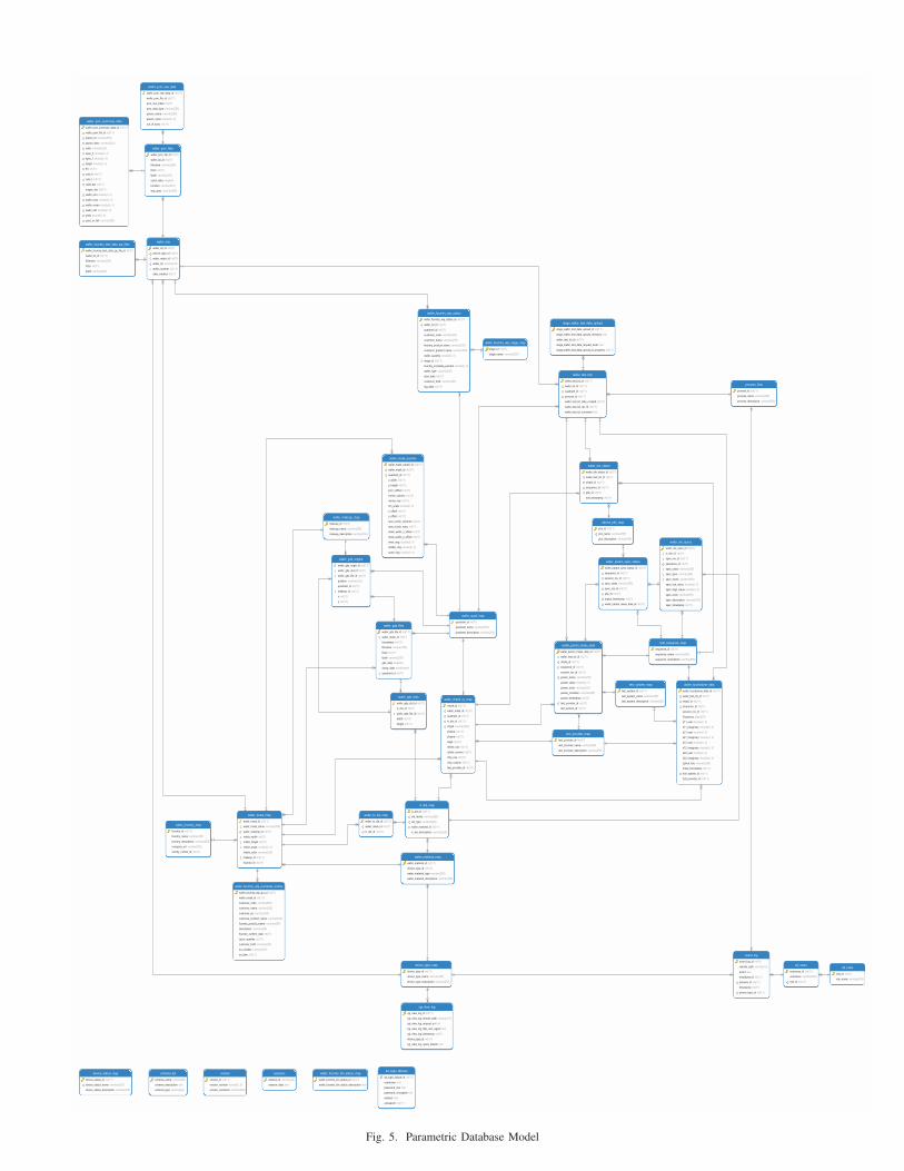
Fig. 5. Parametric Database Model