a measurement study on co-residence threat inside the cloud · network management, and virtual...
TRANSCRIPT
This paper is included in the Proceedings of the 24th USENIX Security Symposium
August 12–14, 2015 • Washington, D.C.
ISBN 978-1-931971-232
Open access to the Proceedings of the 24th USENIX Security Symposium
is sponsored by USENIX
A Measurement Study on Co-residence Threat inside the Cloud
Zhang Xu, College of William and Mary; Haining Wang, University of Delaware; Zhenyu Wu, NEC Laboratories America
https://www.usenix.org/conference/usenixsecurity15/technical-sessions/presentation/xu

USENIX Association 24th USENIX Security Symposium 929
A Measurement Study on Co-residence Threat inside the Cloud
Zhang XuThe College of William and Mary
Haining WangUniversity of Delaware
Zhenyu WuNEC Laboratories America
AbstractAs the most basic cloud service model, Infrastructure as aService (IaaS) has been widely used for serving the ever-growing computing demand due to the prevalence of thecloud. Using pools of hypervisors within the cloud, IaaScan support a large number of Virtual Machines (VMs)and scale services in a highly dynamic manner. How-ever, it is well-known that the VMs in IaaS are vulnerableto co-residence threat, which can be easily exploited tolaunch different malicious attacks. In this measurementstudy, we investigate how IaaS evolves in VM placement,network management, and Virtual Private Cloud (VPC),as well as the impact upon co-residence. Specifically,through intensive measurement probing, we first profilethe dynamic environment of cloud instances inside thecloud. Then using real experiments, we quantify the im-pacts of VM placement and network management uponco-residence. Moreover, we explore VPC, which is a de-fensive network-based service of Amazon EC2 for se-curity enhancement, from the routing perspective. Onone hand, our measurement shows that VPC is widelyused and can indeed suppress co-residence threat. On theother hand, we demonstrate a new approach to achievingco-residence in VPC, indicating that co-residence threatstill exists in the cloud.
1 Introduction
Entering the era of cloud computing, Infrastructure asa Service(IaaS) has become prevalent in providing In-formation Technology (IT) support. IT giants such asAmazon [1], Microsoft [4], and Google [2] have de-ployed large-scale IaaS services for public usage. Em-ploying IaaS, individual IT service providers can achievehigh reliability with low operation cost and no longerneed to maintain their own computing infrastructures.However, IaaS groups multiple third-party services to-gether into one physical pool, and sharing physical re-sources with other customers could lead to unexpected
security breaches such as side-channel [25] and covertchannel [19] attacks. It is well-known that IaaS is vul-nerable to the co-residence threat, in which two cloud in-stances (i.e., VMs) from different organizations share thesame physical machine. Co-residence with the victim isthe prerequisite for mounting a side-channel or covert-channel attack.
The security issues induced by co-residence threathave been studied in previous research. However, mostprevious works focus on “what an attacker can do” [14,19, 25], “what a victim user should do” [24], and “whata cloud vendor would do” [12, 15, 26]. In contrast, tothe best of our knowledge, this measurement work ini-tiates one of the first attempts to understand how cloudservice vendors have potentially reacted to co-residencethreat in the past few years and explore potential newvulnerabilities of co-residence inside the cloud. WhileAmazon Elastic Compute Cloud (EC2) is the pioneer ofIaaS, it has the largest business scale among mainstreamIaaS vendors [11, 18]. Therefore, we focus our studyon Amazon EC2. More specifically, our measurement ismainly conducted in the largest data center hosting EC2services: the northern Virginia data center, widely knownas US-East region.
In our measurement study, we first perform a 15-day continuous measurement on the data center usingZMap [10] to investigate the data center’s business scaleand some basic management policies. With the basicknowledge of the cloud, we explore how EC2 has ad-justed VM placement along with its impact on security.We further evaluate how much effort an attacker needsto expend to achieve co-residence in different circum-stances. Comparing our evaluation results with thosefrom 2008 [14], we demonstrate that the VM placementadjustment made by EC2 during the past few years hasmitigated the co-residence threat.
As network management plays a critical role in cloudperformance and security, we also investigate how thenetworking management in EC2 has been calibrated to
930 24th USENIX Security Symposium USENIX Association
suppress co-residence threat. We conduct large scaletrace-routing from multiple sources. Based on our mea-surements, we highlight how the current networking con-figuration of EC2 is different from what it was anddemonstrate how such evolution impacts co-residence in-side the cloud. In particular, we measure the change ofrouting configuration made by EC2 to increase the diffi-culty of cloud cartography. We also propose a new algo-rithm to identify whether a rack is connected with Top ofRack switch or End of Row switch. With this algorithm,we are able to derive the network topology of EC2, whichis useful for achieving co-residence inside the cloud.
To provide tenants an isolated networking environ-ment, EC2 has introduced the service of Virtual PrivateCloud (VPC). While VPC can isolate the instances fromthe large networking pool of EC2, it does not physicallyisolate the instances. After profiling the VPC usage andthe routing configurations in VPC, we propose a novelapproach to speculating the physical location of an in-stance in VPC based on trace-routing information. Ourexperiments show that even if a cloud instance is hid-den behind VPC, an adversary can still gain co-residencewith the victim with some extra effort.
The remainder of the paper is organized as follows.Section 2 introduces background and related work oncloud measurement and security. Section 3 presents ourmeasurement results on understanding the overview ofAmazon EC2 and its basic management policies. Section4 details our measurement on VM placement in EC2, in-cluding co-residence quantification. Section 5 quantifiesthe impact of EC2-improved network management uponco-residence. Section 6 describes VPC, the most effec-tive defense against co-residence threat, and reveals thehaunted co-residence threat in VPC. Section 7 proposespotential solutions to make the cloud environment moresecure. Finally, Section 8 concludes our work.
2 Background and Related Work
To leverage physical resources efficiently and providehigh flexibility, IaaS vendors place multiple VMs ownedby different tenants on the same physical machine. Gen-erally, a scenario where VMs from different tenantsare located on the same physical machine is called co-residence. In this work, the definition of co-residence isfurther relaxed. We define two VMs located in the samephysical rack as co-residence. Thus, two VMs locatedin the same physical machine is considered as machine-level co-residence, while two VMs located in the samerack is defined as rack-level co-residence.
2.1 Co-residence threatThe threat of co-residence in the cloud was first identifiedby Ristenpart et al. [14] in 2009. Their work demon-
strates that an attacker can place a malicious VM co-resident with a target and then launch certain attacks suchas side channel and covert channel attacks. FollowingRistenpart’s work, Xu et al. [20] studied the bit rate ofcache-based covert channel in EC2. Wu et al. [19] con-structed a new covert channel on a memory bus with amuch higher bit rate, resulting in more serious threatsin an IaaS cloud. Zhang et al. [25] proposed a newframework to launch side channel attacks as well as ap-proaches to detect and mitigate co-residence threat in thecloud [24, 26]. Bates et al. [7] proposed a co-resident wa-termarking scheme to detect co-residence by leveragingactive traffic analysis.
The reason we define different levels of co-residenceis that some attacks do not require VMs to be located onthe same physical machine, but rather in the same rackor in a higher level network topology. For instance, Xuet al. [23] proposed a new threat called power attack inthe cloud, in which an attacker can rent many VMs underthe same rack in a data center and cause a power out-age. There are also some side channel and covert chan-nel attacks that only require the co-residence in the samesub-network [5].
In parallel with our work, Varadarajan et al. [16] per-formed a systematical study on placement vulnerabilityin different clouds. While their work mainly stands atthe attacker side to explore more effective launch strate-gies for achieving co-residence in three different clouds,our work performs an in-depth study to understand theevolution of cloud management and the impact on co-residence threat in Amazon EC2. The two complemen-tary works both support the point that public clouds arestill vulnerable to co-residence threat.
2.2 Measurement in the cloudIn contrast to the measurement on private clouds froman internal point of view[9], the measurement works onpublic data centers are mostly conducted from the per-spective of cloud customers. Wang et al. [17] demon-strated that in a public cloud, the virtualization techniqueinduces a negative impact on network performance ofdifferent instance types. The work of Xu et al. [21] mea-sures network performance in Amazon EC2 and demon-strates a long tail distribution of the latency. Their workalso analyzes the reason behind the long tails and pro-poses a new VM deployment solution to address this is-sue. Bermudez et al. [8] performed a large-scale mea-surement on Amazon AWS traffic. Their study showsthat most web service traffic towards Amazon AWS goesto the data center in Virginia, U.S. Some recent stud-ies [11, 18] measure how web services are deployedin public clouds. They found that although many top-ranked domains deploy their subdomains into the cloud,most subdomains are located in the same region or zone,
2

USENIX Association 24th USENIX Security Symposium 931
Figure 1: The system used to scan EC2.
resulting in a relatively poor fault tolerance.In contrast to those measurement efforts, our study
provides a measurement analysis from the perspective ofsecurity to reveal the management policies of a publiccloud and their impact upon co-residence threat.
3 An Overview of EC2 ManagementAs the pioneer of IaaS, Amazon EC2 deploys its datacenters all around the world, hosting the largest scale ofIaaS business. In this section, we introduce some ter-minology in EC2 and provide an overview of the EC2environment.
3.1 Instance typeAn instance represents a virtual machine (VM) in thecloud, so we use the term “instance” and “VM” inter-changeably throughout the rest of the paper. EC2 pro-vides a list of instance types for clients to select whilelaunching a new instance. The type of an instance in-dicates the configuration of the VM, determining theamount of resources the VM can use. The instance type isdefined in the format XX.XXX such as m1.small. The firstpart of the instance type reveals the model of the physi-cal server that will host this type of instance. The secondpart indicates the “size” of the VM, i.e., the amount ofresources allocated to the instance. The detailed config-uration of different instance types can be found at [3].
3.2 Regions and zonesAmazon EC2 has the concept of “region,” which repre-sents the physical area where the booted instance willbe placed. Amazon has 9 locations around the worldhosting EC2 services. Therefore, the instances in EC2can be located in 9 regions: US east (northern Virginia),US west (Oregon), US west (northern California), SouthAmerica (Sao Paulo), Asia Pacific southeast (Singapore),Asia Pacific southeast (Sydney), Asia Pacific northeast(Tokyo), EU west (Ireland), and EU central (Frankfurt).As pointed out in previous work [11], the majority ofIaaS business is hosted in the US east region, e.g., in thedata center located in northern Virginia. Most existingresearch on cloud measurement was conducted on thisregion [8, 13, 14]. Therefore, we also focus our studyon the US east region. For the rest of the paper, we use
the term “cloud” to mean the EC2 US east region and theterm “data center” to mean the Amazon EC2 data centerin northern Virginia, US.
In addition to regions, Amazon EC2 also allows clientsto assign an instance to a certain “zone.” A zone is alogical partition of the space within a region. Previouswork shows that the instances in the same zone sharecommon characters in private IP addresses, and likely in-stances within the same zone are physically close to eachother [14, 19]. There are four availability zones in theUS east region: us-east-1a, us-east-1b, us-east-1c, andus-east-1d.
3.3 NamingThe naming service is essential to cloud management.On one hand, the naming service can help customers toeasily access their instances and simplify resource man-agement. On the other hand, the naming service shouldhelp the cloud vendor to manage the cloud efficientlywith high network performance.
In EC2, an instance is automatically assigned two do-main names: one public and one private. The publicdomain name is constructed based on the public IP ad-dress of the instance, while the private domain name isconstructed based on either the private IP address or theMAC address. Performing a DNS lookup outside EC2returns the public IP of the instance, while performinga DNS lookup inside EC2 returns the private IP of theinstance.
3.4 Scanning EC2 inside and outsideTo better understand the environment and business scaleof EC2, we performed a 15-day continuous measurementon the EC2 US east region.
Figure 1 illustrates our system to scan EC2. First wedeployed a scanner outside EC2 to scan the cloud througha public IP address. Since EC2 publishes the IP range forits IaaS instances, our scanner uses ZMap [10] to scan thespecified ranges of IP addresses. The ports we scannedinclude: ports 20 and 21 used for FTP, port 22 used forSSH, port 23 for telnet, ports 25 and 587 for SMTP, port43 for WHOIS, port 53 for DNS, port 68 for DHCP, port79 for Finger protocol, port 80 for HTTP, port 118 forSQL, port 443 for HTTPS, and port 3306 for MySQL.We also performed an ICMP echo scan. After scanning,our outside scanner obtained a list of live hosts in EC2with the corresponding public IP addresses. In the nextstep, we performed automatic domain name generation.As mentioned above, the public domain name of an in-stance in EC2 can be derived using its public IP. This stepproduces a list of public domain names of live hosts. Thegenerated public domain names were then sent to our in-side scanner deployed inside EC2. Our inside scannerthen performed DNS lookups for these domain names.
3

932 24th USENIX Security Symposium USENIX Association
Due to the DNS lookup mechanism of EC2, the DNSserver in EC2 answered the queries with the private IPaddresses of the hosts. Reaching this point, our mea-surement system can detect live hosts in EC2 with theirdomain names, IP addresses, as well as the mapping be-tween the public IP address and private IP address.
The scan interval is set to 20 minutes, which is a trade-off between cost and accuracy. Scanning the entire EC2US east region per port takes about 40 seconds, and wehave 14 ports to scan. This means that scanning all theports will take around 10 minutes. Note that our mea-surement also includes DNS lookups for all the detectedlive hosts. Performing these DNS lookups takes around20 minutes, which is approximately the time for tworounds of scanning.
Our scanning measurement provides us an overviewof the large business scale of EC2, the diversity of ser-vices, and the dynamic running environment. This scan-ning measurement also gives us the knowledge base tounderstand co-residence threat. The detailed results andanalysis of our scanning measurement can be found inthe Appendix A and B.
4 The Impact of VM Placement upon Co-residence
The VM placement policy of the cloud determines howeasy or hard it is for an attacker to achieve co-residence.In this section, we present our measurement on VMplacement and quantification of achieving co-residence.By comparing our measurement results with previouswork, we demonstrate how the VM placement policy hasbeen evolving in EC2 and its impact on mitigating co-residence threats.
4.1 Basic understanding of VM placementWe first launched a sufficiently large number of in-stances with different types in EC2. Then, we had twotasks to fulfill: (1) collecting networking (i.e., loca-tion) information of launched instances and (2) quan-tifying co-residence threat, i.e., given the current VMplacement policy of EC2, how much effort an attackerneeds to make to achieve co-residence. Since the pro-cess of achieving co-residence requires the knowledgeof instance location, we can complete the two tasks to-gether. For every instance we launched while seekingco-residence, we recorded its private IP address and pub-lic IP address. We also performed an automatic trace-route from the instance to its “neighbors” that share the/24 prefix with it. This information can provide us thebasic knowledge of where the instances are placed.
During our measurement, we recorded the detailedinformation of 2,200 instances of type t1.micro, 1,800instances of type m1.small, 1,000 instances of type
0 20 40 60 80 100 1200
0.2
0.4
0.6
0.8
1
Private address distance
F(x
)
Empirical CDF
Micro
Small
Figure 2: CDF of IP address distances between co-resident VMs.
m1.medium, 1,000 instances of type m3.medium, 80 in-stances of m3.large, and 40 instances of m3.xlarge. Weselected some random samples from the instances werecorded to study the internal IP distribution. We investi-gated how private IP addresses are associated by the in-stance type and availability zones, i.e., whether the VMplacement has type and zone locality. Our results demon-strate that currently EC2 still exhibits certain type andzone locality, i.e., instances with the same type in thesame zone are more likely to be placed close to one an-other. However, compared with corresponding results in2008 [14], such locality has been significantly weakened.More details of locality comparison can be found in Ap-pendix C.
After understanding the current VM placement inEC2, we further investigate co-residence threats in EC2.
4.2 Quantifying machine level co-residenceTo understand how VM placement will affect co-residence, we assess the effort one needs to make toachieve machine level co-residence in two scenarios. Thefirst scenario is to have a random pair of instances locatedon the same physical machine, and the second scenario isto have an instance co-reside with a targeted victim.
4.2.1 Random co-residence
To make our random co-residence quantification morecomprehensive, we perform our measurement with dif-ferent instance types and in different availability zones.Since zone us-east-1c is no longer hosting t1, m1, c1,and m3 instances, our measurement is performed in zoneus-east-1a, us-east-1b, and us-east-1d. We achieve co-residence pairs with t1.micro, m1.small, m1.medium,and m3.medium. We did not achieve co-residence withlarge, xlarge or 2xlarge instances, because there are only1 to 4 such large instances on one physical machine andit will be very difficult and costly to achieve co-residencewith these types. Overall, we conduct 12 sets of experi-ments, with each set targeting a specific type of instancesin a specific availability zone.
In each set of experiments, we perform rounds ofco-residence probing until we find a co-residence pair.
4

USENIX Association 24th USENIX Security Symposium 933
us−east−1a us−east−1b us−east−1d0
100
200
300
400
Availability Zone
Insta
nces L
aunched
m3.medium
m1.medium
m1.small
t1.micro
Figure 3: The service hour spent, i.e., thenumber of instances booted to achieve co-residence.
us−east−1a us−east−1b us−east−1d0
10
20
30
Availability Zone
Cost ($
)
m3.medium
m1.medium
m1.small
t1.micro
Figure 4: The financial cost (in US dollar) toachieve co-residence.
us−east−1a us−east−1b us−east−1d0
50
100
150
200
Availability Zone
Tim
e T
aken (
min
ute
s)
m3.medium
m1.medium
m1.small
t1.micro
Figure 5: The time spent to achieve co-residence.
For the sake of robustness, EC2 has never placed in-stances from the same user on the same physical ma-chine [14]. Therefore, we set up two accounts to launchinstances simultaneously. Within one round, each ac-count launches 20 instances, which will produce 400pairs of co-residence candidates. Once a co-residencepair is verified, this set of experiments are terminatedand the corresponding cost is recorded. If there is no co-residence pair found in this round, we move on to the nextround by terminating all running instances and launchinganother 20 instances in each account, and then repeat thesame procedure.
Given a pair of instances, verifying whether they arelocated on the same physical machine involves two steps:(1) pre-filtering unlikely pairs and (2) using a covertchannel to justify co-residence.
For the first step, we need to screen out those pairs thatare not likely to be co-resident to reduce probing space.Since the private IP address of an instance can indicateits physical location to some extent, and if the privateIP addresses of two instances are not close enough, thetwo instances will have little chance to be co-resident.Based on this heuristic, we use the share of /24 prefixas the prerequisite of co-residence, i.e., if two instancesdo not share the /24 prefix, we consider them as not be-ing co-resident and bypass the highly costly step 2. Therationale of setting the /24 prefix sharing as pre-filter istwofold:
1. First, the prerequisite of the /24 prefix sharing willnot likely rule out any co-residence instance pairs.The number of instances that are hosted on the samephysical machine is limited. Even for micro in-stances, there are no more than 32 instances run-ning on a physical machine. For the instance typewith larger size, there are even fewer instances run-ning on a physical machine. In contrast, a /24address space can contain 256 instances. There-fore, two co-resident instances are unlikely to bein different /24 subnets. Moreover, we obtainedsome co-residence pairs without any pre-filteringand recorded the private IP address distance be-tween a pair of co-residence instances. Figure 2illustrates the CDF of IP address distance between
two co-residence instances. The distance is calcu-lated as the difference between the two 32-bit inte-gers of the two IP addresses. From the results wecan figure out that most of these co-residence in-stances share the /27 prefix, which further confirmsthat the /24 prefix filtering will introduce very few,if any, false negatives.
2. Second, the prerequisite of sharing the /24 prefixcan effectively narrow down the candidate space.Each time we use one account to launch 20 instancesand use another account to launch another 20 in-stances, we will have 400 candidate pairs. Dur-ing our measurement, we generated more than 40rounds of such 400-pair batches. The average num-ber of instance pairs that share the /24 prefix among400 candidates is only 4. This means the /24 prefixsharing prerequisite can help us to screen out 99% ofthe candidates, which significantly accelerates theprocess of co-residence verification. During the 40rounds of measurement, five co-residence pairs areobserved.
The second step is to use a covert channel to ver-ify whether two instances are actually located on thesame physical machine. We use the technique intro-duced by Wu et al. [19] to construct a memory-bus-basedcovert channel between two instances. If the two in-stances can communicate with each other via the covertchannel, then they are located on the same physical ma-chine. This covert-channel-based verification can guar-antee zero false positives.
The cost of achieving co-residence includes financialcost and time. According to the pay-as-you-go billingsystem, the financial cost is mainly determined by theservice hours consumed during the co-residence prob-ing. Every time an instance is launched, one billinghour is charged. Thus, the more probing instances anattacker needs to launch, the higher financial cost it willcause. In our experiments, we use only two accounts.In a real world attack, an attacker could use more ac-counts to launch the attack in parallel, which will result inless time required to achieve co-residence. However, un-der the same condition, regardless of attack process op-
5
934 24th USENIX Security Symposium USENIX Association
t1.micro m1.small m1.medium m3.medium0
100
200
300
400
500
600
Instance Type
Insta
nces L
aunched
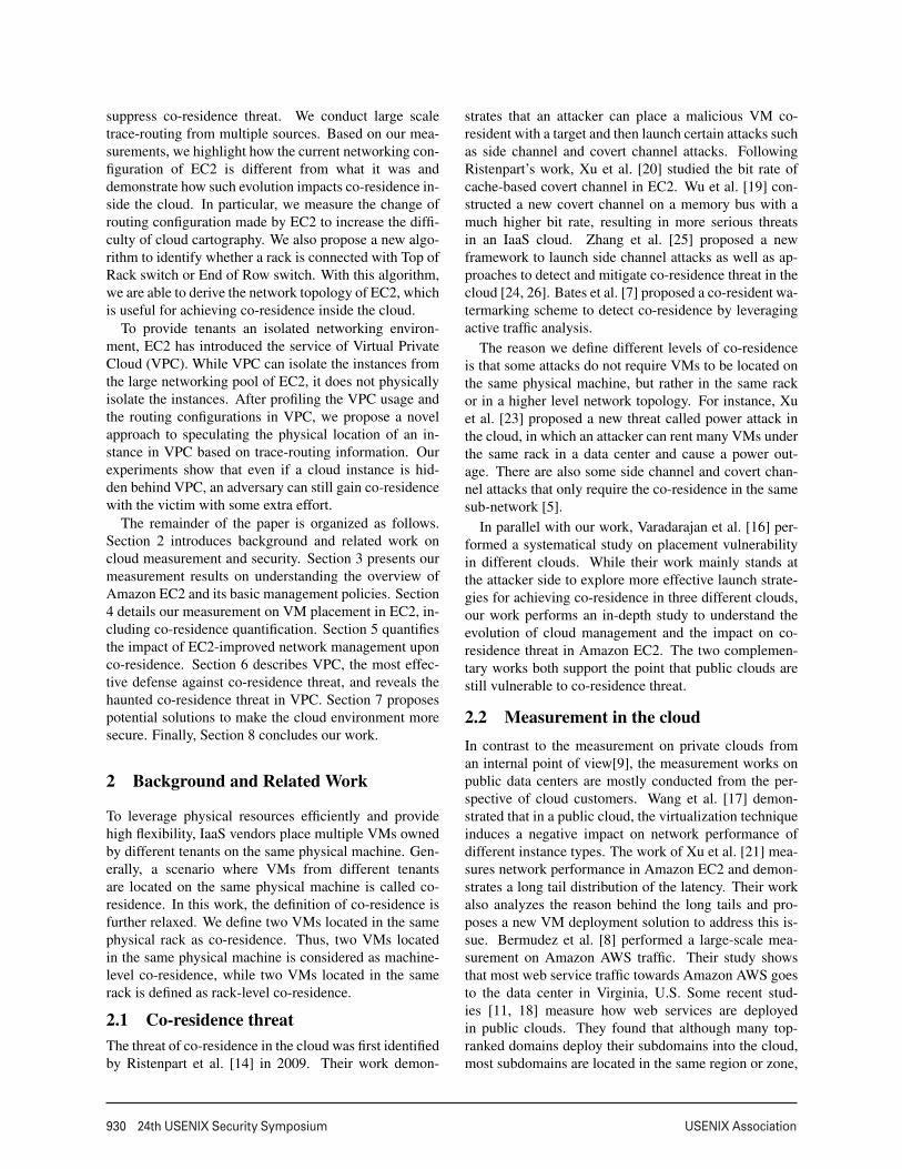
Figure 6: The service hour spent, i.e. the num-ber of instances booted to achieve co-residencewith a target.
t1.micro m1.small m1.medium m3.medium0
10
20
30
40
50
Instance Type
Co
st
($)
Figure 7: The financial cost (in US dollar) toachieve co-residence with a target.
t1.micro m1.small m1.medium m3.medium0
50
100
150
Instance Type
Tim
e T
ake
n(m
inu
tes)
Figure 8: The time spent to achieve co-residence with a target.
timization, the time spent to achieve co-residence shouldhave a positive correlation with the number of instancesto launch, i.e., the more instances need to launch, themore time spent for detecting co-residence.
Figure 3 illustrates how many instances are requiredto achieve co-residence, while Figure 4 illustrates theactual financial cost. Figure 5 illustrates how much timeit takes to achieve co-residence, i.e., the time cost. Foreach type of instance, the measurement repeats for fivetimes and the mean value is shown in the figures. Fromthe figures, it is evident that the cost for achieving co-residence of different types in different availability zonesis quite different. Intuitively, as a larger instance hashigher resource charge, it costs more money to achieveco-residence with those instances at a larger size. How-ever, there is no such rule that the smaller size an instanceis, the lower time cost we need to pay for co-residence.
4.2.2 Target co-residence
In the quantification of achieving co-residence with a par-ticular target, we first randomly launched one instancewith specific type from one account as the target. Then,from the other account, we also performed many roundsof co-residence probing until we found the instance thatis co-resident with the target. The process of verifyingco-residence remains the same. As demonstrated by theverification results of random co-residence above, differ-ent availability zones do not greatly impact the difficultyof achieving co-residence. Here we only show the resultswhen our target instances are placed in zone us-east-1a.
Figures 6, 7 and 8 illustrate the number of instances tolaunch, the financial cost, and the time taken to achieveco-residence with a particular target, respectively. Foreach type of instance, the measurement is repeated for15 times and the mean value is illustrated. The error barwith standard deviation is also shown in the figures. Asis intuitive, achieving co-residence with a particular tar-get requires launching more instances than achieving ran-dom co-residence. Getting a random co-residence pairrequires launching 200 to 300 instances with two ac-counts (i.e., 100 to 150 instances per account), whichcan be done in 5 to 8 rounds. In contrast, achievingco-residence with a particular target requires launching
300 to 400 instances, which will take 15 to 20 roundswith each round launching 20 instances from one ac-count. However, achieving co-residence with a particulartarget does not cost more time than achieving a randomco-residence pair. The reason for this is simple: To geta random pair, we need to check 400 candidate pairs ineach round, but to get a co-residence pair with a target,we only need to check 20 candidates in one round.
It is also possible that an attacker is unable to achieveco-residence with a certain target due to various rea-sons, e.g., the target physical machine reaches full capac-ity. During our study, we failed to achieve co-residencewith two targets, one is m1.medium type and the otheris m3.medium type. By failing to achieve co-residencewe mean that after trying with more than 1,000 probinginstances in two different days, we still cannot achieveco-residence with these two targets.
Overall, it is still very feasible to achieve co-residencein EC2 nowadays. However, an attacker needs to launchhundreds of instances to reach that goal, which may in-troduce considerable cost. In Section 4.4, we will com-pare our results to previous studies, demonstrating thatachieving machine-level co-residence has become muchmore difficult than before, due to the change in cloud en-vironments and VM placement policies.
4.3 Quantifying rack level co-residenceWhile covert channel and side channel attacks requirean attacker to obtain an instance located exactly on thesame physical machine with the victim, some maliciousactivities only need coarse-grained co-residence. Xu etal. [23] proposed a new attack called power attack. Intheir threat model, the attacker attempts to significantlyincrease power consumption of multiple machines con-nected by the same power facility simultaneously to tripthe circuit breaker (CB). Since these machines locatedin the same rack are likely to be connected by the sameCB, in a power attack the attack instances are not re-quired to be placed on a same physical machine. Insteadthe attacker should place many instances within the samerack as the victim, i.e., achieving as much rack-level co-residence as possible. We performed measurement onhow much effort is required to place a certain number of
6
USENIX Association 24th USENIX Security Symposium 935
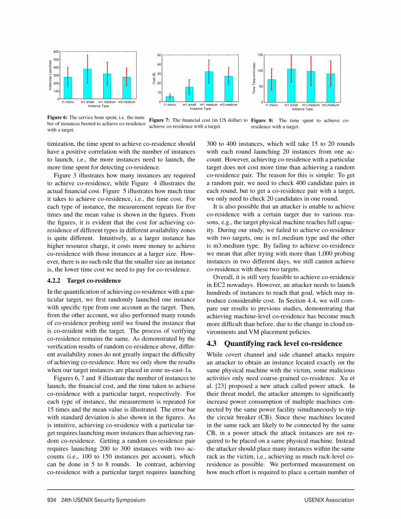
Table 1: The number of co-residence pairs achieved by one round ofprobing in 2008 [14].
Account A Account B Co-residence
Zone 11 20 1
10 20 520 20 7
Zone 21 20 0
10 20 320 20 8
Zone 31 20 1
10 20 220 20 8
instances under the same rack.We first use one account to launch 20 instances, and
then we check whether there are any instances in thisbatch that are located within the same rack. If there areno instances located in the same rack, we just randomlypick an instance and set its hosting rack as the target rack.Thanks to the Top of Rack(ToR) switch topology, verify-ing whether two instances are in the same rack is simple.Through a simple trace-routing, we can verify whether aninstance has the same ToR switch with our target rack.This rack level co-residence can be further verified byperforming trace-route from the candidate instance to thetarget instance. If the two instances are in the same rack,there should be only one hop in the trace, i.e., they areone hop away.
Figure 9 shows our measurement results. It is clearthat an attacker can easily have multiple instances lo-cated within the same rack. The information of ToRswitch helps the attacker quickly verify the rack-levelco-residence. Since the malicious attack based on therack-level co-residence is newly proposed [23], EC2 isunlikely to take any action to suppress rack-level co-residence.
4.4 Battle in VM placementTable 1 lists the data from the original work on co-residence [14]. We can see that it was extremely easyto achieve co-residence in 2008. With two accounts eachlaunching 20 instances, there were 7 or 8 co-residencepairs observed. In the 2012 work [19], the cost of achiev-ing a co-residence instance pair is also briefly reported: Aco-residence pair (micro) is achieved with 160 instancesbooted.
As we can see, nowadays it is much more difficult toachieve co-residence than in 2008 and 2012. EC2 couldhave adjusted its VM placement policies to suppress co-residence.
4.4.1 A larger pool
The business of EC2 is scaling fast, and thus it is intuitivethat Amazon keeps deploying more servers into EC2.The measurement in 2008 [14] shows that there werethree availability zones in the US east region. At present,the availability zones are expanded to four. Such expan-
sion in availability zones also indicates that the businessscale of EC2 is growing rapidly.
The measurement in 2008 [14] also shows 78 uniqueDomain0 IP addresses with 1785 m1.small instances,which means it only observed 78 physical machines thathost m1.small service. Due to the evolution in EC2 man-agement, we are no longer able to identify Dom0. How-ever, we have identified at least 59 racks of servers thathost m1.small instances. This suggests that the numberof physical machines hosting m1.small instances is sig-nificantly larger than that in 2008. The enlarged pool pro-vides EC2 with more flexibility to place incoming VMs,which is one of the reasons that it is now much more dif-ficult to achieve co-residence than before.
4.4.2 Time locality
Time locality can help to achieve co-residence. Time lo-cality means if two accounts launch instances simultane-ously, it is more likely that some of these instances withtime locality will be assigned to the same physical ma-chine.
To verify whether such time locality exists in the cur-rent EC2, we performed another measurement. We setup four groups of experiments. In the first group, the twoaccounts always launch 20 VMs simultaneously. In thesecond group, the second account launches 20 VMs 10minutes after the first account launches 20 VMs. In thethird group, the launching time of the second account isone hour apart from that of the first account. In the fourthgroup, the second account launches VMs four hours af-ter the first account. All instances are t1.micro type. Ineach group, the measurement terminates whenever a co-residence pair is observed and the number of instancesrequired to achieve co-residence is recorded. All the ex-periments are repeated 5 times and the average is noted.
Figure 10 illustrates the number of instances requiredto achieve co-residence in each case. We can see thatthe efforts required to achieve co-residence do not varysignificantly with the change of instance launching in-tervals. This implies that time locality seems to be veryweak in the current EC2, which increases co-residencecost.
4.4.3 Dynamic assignment
In 2008, the IP addresses and instances in EC2 were as-signed in a relatively static manner [14]. However, as wehave demonstrated before, there are considerable map-ping changes in our measurement, which indicates thatthe IP assignment has introduced a certain dynamism.
Meanwhile, in 2008, the instances were placed strictlybased on the instance type, i.e., one physical machinecan only host one type of instance [14]. In contrast, ourmeasurement results show that such an assumption maynot hold anymore. First, some small instances use in-ternal IP addresses that were used by micro instances
7

936 24th USENIX Security Symposium USENIX Association
2 4 6 8 10 12 14 16 18 200
100
200
300
400
500
600
Number of Instances in a Rack
Insta
nces L
aunched
Figure 9: Instances launched to place certain number of instanceswithin the same rack.
0 minute 10 minutes 1 hour 4 hours0
50
100
150
200
250
300
Interval
Insta
nce
s L
au
nch
ed
Figure 10: Effort to achieve co-residence with different time lo-cality.
before. Second, during our measurement, by accidentwe observed that one live small instance has very closeIP to a medium instance. We then attempted to builda covert channel between them. It turned out that thecovert channel did work, which verifies that these two in-stances with different types are indeed located on a samephysical machine. Following such an observation, in therest of our rest measurement we also kept checking co-residence between different types of instances. Overall,five pairs of different-type co-residence instances are ob-served throughout our study. Our results indicate that incertain cases current VM placement policies in EC2 canmix different types of instances on one physical machine,potentially to reduce fragmentation. Such a policy alsoincreases the difficulty of achieving co-residence.
5 The Impact of Network Managementupon Co-residence
As network management plays a critical role in datacenter management, it has a significant impact on co-residence. On one hand, an attacker attempts to obtainas much networking information inside the cloud as pos-sible to ease the gaining process of co-residence. On theother hand, the cloud vendors try to protect sensitive in-formation while not degrading regular networking man-agement and performance. In this section, we introducethe adjustments made by EC2 in network managementduring recent years to mitigate co-residence threat andthe effectiveness of these approaches.
5.1 MethodologyTo study the adjustment made by EC2 in network man-agement, we performed large scale trace-routing. First,for the instances we booted, we performed “neighbor-hood trace-routing” from our instances to their “neigh-bors.” Here we define neighbors as all those instancesthat share the /23 prefix of their private IP addresses withour source instances. Such trace-routing can inform us ofthe routing paths between an instance and other instances
in the same rack and neighboring racks.We next performed trace-routing from several of our
instances (i.e., the instances we booted) to all the in-stances in a target list. We use the live host list from ourscanning measurement (see Section 3.5 and Appendix A)as the target list. Trace-routing from our instances to over650,000 target instances takes more than 8 days, but itcan help us to understand network management in EC2in a more comprehensive manner.
5.2 The evolution in routing configurationThe routing information has been leveraged to performcloud cartography [14], which can further be used tolaunch co-residence-based attacks. However, our trace-routing results demonstrate that, as a response to cloudcartography, EC2 has adjusted its routing configurationsto enhance security in the past few years. The adjust-ments we found are listed as follows.
5.2.1 Hidden Domain0
EC2 uses XEN as the virtualization technique in thecloud. According to the networking I/O mechanism ofXEN [6], all the network traffic of guest VMs (instances)should travel through the privileged instance: Domain-0 (i.e, Dom0). Thus, Dom0 acts as the gateway of allinstances on the physical machine, and all instances onthis physical machine should have the same first-hop intheir routing paths. Such Dom0 information provides anattacker with a very efficient probing technique: by sim-ply checking the Dom0’s IP addresses of two instances,one can know whether they are co-resident. Therefore,to prevent this Dom0 information divulgation, EC2 hashidden Dom0 in any and all routing paths, i.e. at presentthe Dom0 does not appear in any trace-routing results.
5.2.2 Hidden hops
To suppress cloud cartography enabled by trace-routing,EC2 has hidden certain hops in the routing paths. Ac-cording to the work in May 2013 [13], traffic only needsto traverse one hop between two instances on the samephysical machine and two hops between instances in
8
USENIX Association 24th USENIX Security Symposium 937
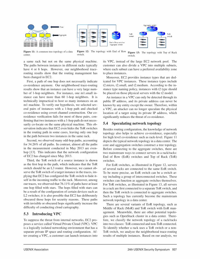
Figure 11: A common tree topology of a datacenter.
Figure 12: The topology with End of Rowswitch.
Figure 13: The topology with Top of Rackswitch.
a same rack but not on the same physical machine.The paths between instances in different racks typicallyhave 4 or 6 hops. However, our neighborhood trace-routing results show that the routing management hasbeen changed in EC2.
First, a path of one hop does not necessarily indicateco-residence anymore. Our neighborhood trace-routingresults show that an instance can have a very large num-ber of 1-hop neighbors. For instance, one m1.small in-stance can have more than 60 1-hop neighbors. It istechnically impractical to host so many instances on anm1 machine. To verify our hypothesis, we selected sev-eral pairs of instances with a 1-hop path and checkedco-residence using covert channel construction. Our co-residence verification fails for most of these pairs, con-firming that two instances with a 1-hop path do not neces-sarily co-locate on the same physical machine. This ob-servation indicates that EC2 even hides the ToR switchesin the routing path in some cases, leaving only one hopin the path between two instances in the same rack.
Second, we observed many odd-hop paths, accountingfor 34.26% of all paths. In contrast, almost all the pathsin the measurement conducted in May 2013 are even-hop [13]. This indicates that the network configurationof EC2 has changed since May 2013.
Third, the ToR switch of a source instance is shownas the first hop in the path, which indicates that the ToRswitch should be an L3 router. However, we cannot ob-serve the ToR switch of a target instance in the traces, im-plying that EC2 has configured the ToR switch to hide it-self in the incoming traffic to the rack. Moreover, amongour traces, we observed that 76.11% of paths have at leastone hop filled with stars. The hops filled with stars canbe a result of the configuration of certain devices such asL2 switches; it is also possible that EC2 has deliberatelyobscured those hops for security reasons. These pathswith invisible or obscured hops significantly increase thedifficulty of conducting cloud cartography.
5.3 Introducing VPCTo suppress the threat from internal networks, EC2 pro-poses a service called Virtual Private Cloud (VPC). VPCis a logically isolated networking environment that has aseparate private IP space and routing configuration. Af-ter creating a VPC, a customer can launch instances into
its VPC, instead of the large EC2 network pool. Thecustomer can also divide a VPC into multiple subnets,where each subnet can have a preferred availability zoneto place instances.
Moreover, EC2 provides instance types that are ded-icated for VPC instances. These instance types includet2.micro, t2.small, and t2.medium. According to the in-stance type naming policy, instances with t2 type shouldbe placed on those physical servers with the t2 model.
An instance in a VPC can only be detected through itspublic IP address, and its private address can never beknown by any entity except the owner. Therefore, withina VPC, an attacker can no longer speculate the physicallocation of a target using its private IP address, whichsignificantly reduces the threat of co-residence.
5.4 Speculating network topologyBesides routing configuration, the knowledge of networktopology also helps to achieve co-residence, especiallyfor high level co-residence such as rack-level. Figure 11depicts the typical network topology in a data center. Thecore and aggregation switches construct a tree topology.Before connecting to the aggregate switches, there aretwo mainstream ways to connect servers in a rack/racks:End of Row (EoR) switches and Top of Rack (ToR)switches.
For EoR switches, as illustrated in Figure 12, serversof several racks are connected to the same EoR switch.To be more precise, an EoR switch can be a switch ar-ray including a group of interconnected switches. Theseswitches can function as aggregate switches themselves.For ToR switches, as illustrated in Figure 13, all serversin a rack are first connected to a separate ToR switch, andthen the ToR switch is connected to aggregate switches.Such a topology has currently become the mainstreamnetwork topology in a data center.
There are several variants of EoR topology, such asMiddle of Rack (MoR) and ToR switch with EoR man-agement. Meanwhile, there are other potential topolo-gies such as OpenStack cluster in a data center. There-fore, we classify the network topology of a rack/racksinto two classes: ToR connected and non-ToR connected.To identify whether a rack uses a ToR switch or a non-ToR switch, we analyze the neighborhood trace-routingresults of multiple instances. Based on our analysis, we
9

938 24th USENIX Security Symposium USENIX Association
proposed a method to identify the network topology of arack, ToR-connected or non-ToR-connected.
ToR-connected: a rack that deploys ToR switchesmust satisfy all of the following conditions:
1. For an instance A in the rack, there should be at leastone instance B that is only one hop away from A.
2. For an instance A in the rack, there should be at least8 instances that are two hops away from A.
3. For any two instances A and B, if (i) conditions 1and 2 hold for both A and B, (ii) the trace-routingpath between A and B has no more than two hops,and (iii) for any instance C, the first hop in the trace-routing path from A to C is the same as the first hopin the path from B to C, then A and B are consideredas being in the same ToR rack.
4. For an instance A in the rack, for any trace-routingpath with A as source and length larger than 2, thefirst hop in the path should share the /16 prefix withthe private IP address of A.
The IP address of the first hop (i.e., ToR switch’s IP ad-dress) is used to differentiate two ToR racks.
Non-ToR-connected: a rack that deploys non-ToRswitches must satisfy all of the following conditions:
1. For an instance A in the rack, there should be noinstance B such that the path between A and B hastwo hops.
2. For an instance A in the rack, for any instance Bin EC2, either (i) A and B are machine-level co-resident and the path between A and B has only onehop or (ii) the path between A and B has more thantwo hops.
3. For two instances A and B, if (i) conditions 1 and2 hold for both A and B, (ii) A and B share the /24prefix of their private IP, (iii) the trace-routing pathbetween A and B has 4 or 6 hops, and (iv) for anyinstance C, the first hop in the path between A andC is the same as the first hop in the path between Band C, then A and B are considered as being in thesame non-ToR rack.
4. For an instance A in the rack, for any trace-routingpath with A as source and length larger than 2, thefirst hop in the path should not share the /20 prefixwith the private IP address of A.
Again, the IP address of the first hop is used to differen-tiate two non-ToR racks.
In EC2, there are two “generations” of instances. Theold generation carries all the instances with m1 type, andthe new generation covers all the instances with othertypes. We applied our method on m1.small, m1.medium,m3.medium, and m3.large type, which cover both old-generation instances and new-generation instances.
Overall, we identified 59 distinct racks that hostm1.small instances, 18 racks that host m1.medium in-stances, 22 racks that host m3.medium instances, and
10 racks that host m3.large instances. Among the 109racks, there are only 14 racks identified as non-ToR-connected while the rest are ToR-connected. Among the14 non-ToR racks, we observed 12 old-generation racks,in which 7 racks host m1.small instances and 5 racks hostm1.medium instances, and only 2 new-generation rackshost m3.medium instances.
Our results demonstrate that while both ToR racks andnon-ToR racks exist in EC2, ToR-connected is the dom-inating topology in EC2. Moreover, it is evident thatnew-generation machines are more likely to be locatedin the ToR-connected topology, indicating that the ToR-connected topology has become the main trend. Whilethe ToR-connected topology is easy to manage, the rout-ing information is very straightforward since the first hopreveals which rack the instance is in. Such informationcan be leveraged by an attacker to achieve rack-level co-residence.
6 A New Battle in VPCUsing VPC, customers can protect their instances in anisolated network environment. However, VPC only logi-cally isolates the networks. The instances from differentVPCs may still share the same physical machine, leavingthe opportunity to achieve co-residence. In this section,we first take an overview on the usage of VPC in EC2,and then we introduce a new method to attack instancesthat are hidden behind VPCs.
6.1 The overview of VPC usageFor those instances in the default networks of EC2, ourinside scanner can obtain their private addresses via DNSlookups. However, the DNS query for an instance ina VPC will only return its public IP address. There-fore, the instances in a VPC can be easily identified bychecking the DNS query results of our inside scanner,i.e., any instance whose private IP address cannot be de-tected by our inside scanner is an instance in a VPC. Fig-ure 14 shows the VPC usage in EC2. As we can see,all instances in VPC are assigned public IP addressesin five different ranges: 107.20.0.0/14, 184.72.64.0/18,54.208.0.0/15, 54.236.0.0/15, and 54.80.0.0/13. This im-plies that all instances in a VPC are managed in a uni-form manner. On average, in each round of our probingwe can observe 115,801 instances in a VPC, which arearound 17% of all live instances observed, demonstrat-ing that VPC is widely used in EC2 to protect instances.
6.2 Routing paths of VPC instancesSince a VPC should be treated as a private network, therouting policies for instances inside a VPC must be dif-ferent from those in the default EC2 network. This rout-ing difference can help us further understand the manage-ment of a VPC. To connect a VPC to the public Internet, a
10

USENIX Association 24th USENIX Security Symposium 939
0 200 400 600 800 1000 12000
1
2
3
4
x 104
Round of measurment
Nu
mb
er
of
ho
sts
with
no
priva
te I
P
107.20.0.0/14
184.72.64.0/18
54.208.0.0/15
54.236.0.0/15
54.80.0.0/13
Figure 14: The live instances in VPCs.
customer must create a gateway and attach it to the VPC.The gateway must be included into the route table of theVPC. All traffic from or to the Internet must go throughthe gateway, but the traffic inside EC2 does not requirethe gateway to be involved.
Besides the basic understanding of the routing config-uration of a VPC, we also need to know how a VPC isconnected with the default EC2 network and other VPCs.We created several VPCs with two different accounts.The instances with different types are launched into theseVPCs. Trace-routing is performed in four different ways:(1) trace-routing from an instance in a VPC to anotherinstance in the same VPC, (2) trace-routing from an in-stance in a VPC to an instance in another VPC, (3) trace-routing from an instance in a VPC to an instance in thedefault EC2 network, and (4) trace-routing from an in-stance in the default EC2 network to an instance in aVPC.
6.2.1 Routing within VPC
Routing inside the same VPC is expected to be simple.We performed trace-routing between two instances in thesame VPC, using both private and public IP addresses.The results show that trace-routing with private IP orpublic IP addresses will yield different routing paths. Iftrace-routing is performed with the private IP of the tar-get instance, the result path has only one-hop, i.e., thedirect connection to the destination, which is reasonable.However, if trace-routing is performed with the public IPof the target, trace-routing will return two hops with thefirst hop obscured with stars. Apparently, EC2 intention-ally hides some routing information. The routing infor-mation between the two instances within the same VPCis made transparent to customers. Such obscuration dis-ables a customer from speculating the physical locationof the instances.
As discussed in Section V, even within the same VPC,two instances can be located in different “subnets.” Wealso performed trace-routing between two instances inthe same VPC but in different subnets. The resultingpaths do not differ from the paths between two instanceswithin the same subnet.
6.2.2 Routing between VPCs
The traffic between instances in different VPCs shouldtraverse multiple switches and routers. Surprisingly, wefound that any routing path between any two instances inany two different VPCs only has two hops: the first hop isobscured and the second hop is the destination. EC2 onceagain obscures the routing path between VPCs to preventan adversary from revealing sensitive information of aVPC, e.g., the IP address of a gateway.
6.2.3 Routing from VPC to default EC2 network
Although instances in a VPC no longer share a pri-vate network with the default pool of EC2, theswitches/routers that connect VPCs might still be physi-cally connected to the other switches/routers in the datacenter. How EC2 routes the traffic between instances in aVPC and instances in the default EC2 network can revealits network topology to some extent. Figure 15 showsa sample trace-routing result from an instance in a VPCto an instance in the default EC2 network. We can seethat the first two hops of the path are obscured. This pre-vents us from knowing the switch/router that connectsthe VPC, thereby hiding the physical location of VPCinstances. However, we can still see parts of the pathand can infer the end-to-end latency based on the trace-routing result.
6.2.4 Routing from default EC2 network to VPC
Figure 16 shows a sample trace-routing result from aninstance in the default EC2 network to an instance in aVPC. The path is almost symmetric to the path from aVPC to the default EC2 network. Again, the last twohops before reaching the destination are obscured to hidethe information of the router/switch.
Overall, EC2 manages a VPC in a transparent fashion,i.e., to a customer it should look like all instances in aVPC are connected by a dedicated switch, just like a realprivate network. However, instances in the same VPCare not physically located together. These instances arestill located in different racks and are connected to differ-ent ToR or EoR switches. Thus, the traffic inside a VPCmight still traverse multiple switches/routers. Similarly,the traffic between an instance in a VPC and an instancein the default EC2 network can have a similar path to thetraffic between two instances in the default EC2 network.However, EC2 hides or obscures certain hops in the pathto provide the image of “private network.”
6.3 Co-residence in VPCThe traditional way of achieving co-residence relies onthe knowledge of private IP address to seek potential can-didates. With VPC, this approach no longer works asVPC hides the private IP address of an instance. An alter-native is to infer the physical location of a target based on
11

940 24th USENIX Security Symposium USENIX Association
Figure 15: A sample trace-routing result from an instance in VPCto an instance in EC2.
Figure 16: A sample trace-routing result from an instance in EC2to an instance in VPC.
the routing paths to the target. Unfortunately, our trace-routing results show that sensitive information of a rout-ing path is obscured by EC2, and therefore it also doesnot work well.
However, in our trace-routing results we found thatthe end-to-end latency to and from an instance in a VPCvaries with different instance types and the location ofthe instance. This latency variation can be leveraged tohelp an attacker speculate the type and location of a tar-get instance. Moreover, while performing trace-routingbetween an instance in a VPC and an instance in the de-fault EC2 network, the number of hops required is notobscured. Therefore, the number of hops in a path canalso be leveraged to derive useful information for achiev-ing co-residence.
Based on our measurement analysis, we propose a newmethod to achieve co-residence with instances in a VPC.It has two steps: (1) speculate the type and availabilityzone of a target and (2) launch probing instances withthe same type in the same availability zone and performco-residence verification.
6.3.1 Type and zone speculation
We collected statistical data of the end-to-end latency be-tween a pair of instances with different types and in dif-ferent zones. Table 2 shows part of the end-to-end latencystatistics. Each row represents an instance in a VPC witha certain type and availability zone preference. Each col-umn stands for an instance in the default EC2 networkwith a certain type and availability zone preference. Eachvalue in the table is calculated as the average of 50 sam-ples. Each sample is obtained with a distinct instancepair and is averaged over five rounds of latency measure-ment. With this latency table, we are able to construct alatency vector for each target instance in a VPC and usethe latency vectors to speculate the type and availabilityzone of a target.
There are three availability zones and each zone hassix types: t1.micro, m1.small, m1.medium, m1.large,m3.medium, and m3.large. Thus, the complete versionof Table 2 has 18 rows and 18 columns, which can befound in our technical report [22]. Note that each rowin the table can represent a latency vector, and such alatency vector derived from our controlled sampling iscalled a baseline vector.
In each different availability zone, we randomly se-
lect an instance for each different type, resulting in 18(3×6) sample instances in total for testing type and zonespeculation. For each target in a VPC, we perform trace-routing from each of our sample instances to the target for5 times and record the average end-to-end latency of eachpair. Such measurement can provide us 18 end-to-end la-tency values, which constitute an input vector of length18. We then calculate the cosine similarity between theinput vector and these 18 baseline vectors. The baselinelatency vector that has the highest similarity with the tar-get input vector is selected, and we can speculate that thetarget instance has the same {instance type, availabilityzone} as the instance in the selected baseline vector.
6.3.2 Verifying co-residence
To achieve co-residence with an instance in a VPC, ourprobing instances are also launched in a VPC. There aretwo reasons that we do not use the instances in the defaultEC2 network as probing instances. First, it is possiblethat EC2 uses a separate algorithm to place instances ina VPC. In other words, compared to an instance in thedefault EC2 network, an instance in a VPC may have abetter chance to achieve co-residence with an instance inanother VPC. Second, as we have observed, the end-to-end latency between two instances in two different VPCsis more stable than the latency between an instance in thedefault EC2 network and an instance in a VPC, whichallows us to leverage latency for pre-filtering.
Similar to verifying co-residence in the default EC2network, verifying co-residence in a VPC also includestwo steps: pre-filtering and covert channel construction.While the way of using covert channel construction toconfirm co-residence remains the same, the pre-filteringprocess in a VPC is different.
To verify whether an attack instance is co-resident witha target, we rely on two rounds of pre-filtering to screenout irrelevant candidates. First, we perform trace-routingfrom our 18 sample instances to our attack instance andthe target instance. If any path from the sample instanceto the attack instance is not equivalent to the correspond-ing path from the sample instance to the target in termsof number of hops, this attack instance is abandoned.
Second, if all the paths match in the number of hops,we measure end-to-end latency between our attack in-stance and the target instance. Figure 17 shows a sam-ple latency distribution between an instance in a VPC
12

USENIX Association 24th USENIX Security Symposium 941
Table 2: End to end latency between different instances.
1a-t1.micro 1a-m1.small 1a-m1.medium 1b-t1.micro 1b-m1.small 1b-m1.medium1a-t1.micro 1.224ms 1.123ms 1.025ms 2.237ms 2.221ms 2.304ms1a-m1.small 1.361ms 1.059ms 1.100ms 2.208ms 2.055ms 2.198ms1a-m1.medium 1.165ms 1.102ms 0.986ms 2.211ms 2.060ms 1.988ms1b-t1.micro 2.101ms 2.235ms 2.188ms 1.108ms 1.243ms 1.202ms1b-m1.small 2.202ms 2.003ms 2.190ms 1.131ms 0.968ms 1.048ms1b-m1.medium 2.087ms 2.113ms 1.965ms 1.088ms 1.023ms 0.855ms
0 2 4 6 8 10
x 104
0
1
2
3
4
5
Index of target instance
Late
ncy (
ms)
Figure 17: End-to-end latency between an instance in VPC and allother instances in other VPCs in EC2.
with the micro type in availability zone 1a to all liveVPC instances in EC2. As we can see, most end-to-endlatency values (over 99%) are above 1ms, and in veryrare cases (below 0.1%) the latency is below 0.850ms.We perform such latency measurement from 18 sampleVPC instances with different types in different availabil-ity zones, and similar distribution is repeatedly observed.Based on such observations and the heuristics that in-stances located on the same physical machine shouldhave lower latency than instances located in a differentphysical location, we set a latency threshold for each typeof instance in each availability zone. The threshold is se-lected so that for an instance in a VPC with certain typeand availability zone, the end-to-end latency between theinstance and 99.9% of all other VPC instances shouldbe above the threshold. For example, based on our mea-surement introduced above, if we speculate that the targetVPC instance is located in availability zone 1a with mi-cro type, the latency threshold is set to 0.850ms. Onlyif the end-to-end latency between a probing instance anda target instance is below the threshold, will the probinginstance be considered as a co-residence candidate.
If the probing instance passes the two rounds of filter-ing, we will perform covert-channel construction to con-firm co-residence.
6.4 VPC co-residence evaluationTo verify the feasibility of our VPC co-residence ap-proach, we conducted a series of experiments in EC2. Wefirst tested whether our approach can speculate the typeand availability zone of a target instance correctly. Welaunched VPC instances in three availability zones withsix different types. For each combination, 20 instanceswere launched. We applied our approach to speculate
0 1 2 3 4 5 6 7 8 9 10111213141516171819200
500
1000
1500
Target
Pro
bin
g I
nsta
nce
s
Figure 18: The effort for co-residence with instances in VPC.
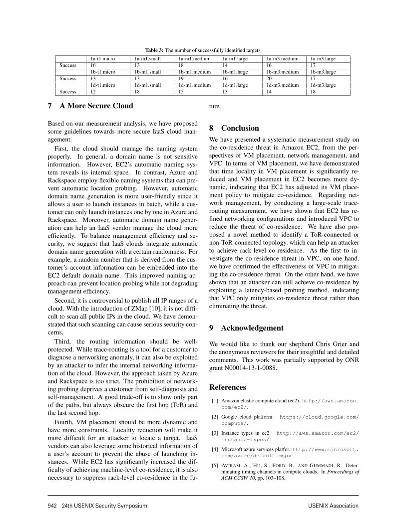
the type and availability zone of the target. If both thetype and availability zone are correctly inferred, we con-sider that the target instance is correctly identified. Ta-ble 3 lists our evaluation results. Each number in thetable indicates the number of the successfully identifiedinstances among the 20 launched instances for a zone-type combination (e.g., 1a-t1.micro means t1.micro in-stances launched in the us-east-1a zone). The resultsshow that our type/zone speculation can achieve an ac-curacy of 77.8%.
We then evaluated the overall effectiveness of our ap-proach for achieving co-residence. We launched 40 in-stances in one VPC, with different types and availabilityzones. We performed the full process of achieving co-residence with VPC instances.
First, we measured the effectiveness of our two-stagefiltering technique. Among all the probing instances welaunched, 63.2% of them did not pass the first step fil-tering. For the second stage, our technique filtered out97.9% of the instances that passed the first stage filter-ing. For all the instances passed the two-stages filter-ing, 17.6% of them passed the covert-channel verifica-tion, which are the instances actually co-resident with thetarget.
Eventually, among 40 instances, we successfullyachieved co-residence with 18 of them. Figure 18 illus-trates the effort we paid to achieve co-residence, showingthat to achieve co-residence in VPC is not an easy task.An attacker may need to launch more than 1,000 probinginstances and such a process can take many hours.
Overall, we are the first to demonstrate that an attackercan achieve co-resident with a target inside a VPC withhigh cost, and hence VPC only mitigates co-residencethreat rather than eliminating the threat all together.
13
942 24th USENIX Security Symposium USENIX Association
Table 3: The number of successfully identified targets.
1a-t1.micro 1a-m1.small 1a-m1.medium 1a-m1.large 1a-m3.medium 1a-m3.largeSuccess 16 13 18 14 16 17
1b-t1.micro 1b-m1.small 1b-m1.medium 1b-m1.large 1b-m3.medium 1b-m3.largeSuccess 13 13 19 16 20 17
1d-t1.micro 1d-m1.small 1d-m1.medium 1d-m1.large 1d-m3.medium 1d-m3.largeSuccess 12 18 15 13 14 18
7 A More Secure Cloud
Based on our measurement analysis, we have proposedsome guidelines towards more secure IaaS cloud man-agement.
First, the cloud should manage the naming systemproperly. In general, a domain name is not sensitiveinformation. However, EC2’s automatic naming sys-tem reveals its internal space. In contrast, Azure andRackspace employ flexible naming systems that can pre-vent automatic location probing. However, automaticdomain name generation is more user-friendly since itallows a user to launch instances in batch, while a cus-tomer can only launch instances one by one in Azure andRackspace. Moreover, automatic domain name gener-ation can help an IaaS vendor manage the cloud moreefficiently. To balance management efficiency and se-curity, we suggest that IaaS clouds integrate automaticdomain name generation with a certain randomness. Forexample, a random number that is derived from the cus-tomer’s account information can be embedded into theEC2 default domain name. This improved naming ap-proach can prevent location probing while not degradingmanagement efficiency.
Second, it is controversial to publish all IP ranges of acloud. With the introduction of ZMap [10], it is not diffi-cult to scan all public IPs in the cloud. We have demon-strated that such scanning can cause serious security con-cerns.
Third, the routing information should be well-protected. While trace-routing is a tool for a customer todiagnose a networking anomaly, it can also be exploitedby an attacker to infer the internal networking informa-tion of the cloud. However, the approach taken by Azureand Rackspace is too strict. The prohibition of network-ing probing deprives a customer from self-diagnosis andself-management. A good trade-off is to show only partof the paths, but always obscure the first hop (ToR) andthe last second hop.
Fourth, VM placement should be more dynamic andhave more constraints. Locality reduction will make itmore difficult for an attacker to locate a target. IaaSvendors can also leverage some historical information ofa user’s account to prevent the abuse of launching in-stances. While EC2 has significantly increased the dif-ficulty of achieving machine-level co-residence, it is alsonecessary to suppress rack-level co-residence in the fu-
ture.
8 ConclusionWe have presented a systematic measurement study onthe co-residence threat in Amazon EC2, from the per-spectives of VM placement, network management, andVPC. In terms of VM placement, we have demonstratedthat time locality in VM placement is significantly re-duced and VM placement in EC2 becomes more dy-namic, indicating that EC2 has adjusted its VM place-ment policy to mitigate co-residence. Regarding net-work management, by conducting a large-scale trace-routing measurement, we have shown that EC2 has re-fined networking configurations and introduced VPC toreduce the threat of co-residence. We have also pro-posed a novel method to identify a ToR-connected ornon-ToR-connected topology, which can help an attackerto achieve rack-level co-residence. As the first to in-vestigate the co-residence threat in VPC, on one hand,we have confirmed the effectiveness of VPC in mitigat-ing the co-residence threat. On the other hand, we haveshown that an attacker can still achieve co-residence byexploiting a latency-based probing method, indicatingthat VPC only mitigates co-residence threat rather thaneliminating the threat.
9 Acknowledgement
We would like to thank our shepherd Chris Grier andthe anonymous reviewers for their insightful and detailedcomments. This work was partially supported by ONRgrant N00014-13-1-0088.
References[1] Amazon elastic compute cloud (ec2). http://aws.amazon.
com/ec2/.
[2] Google cloud platform. https://cloud.google.com/compute/.
[3] Instance types in ec2. http://aws.amazon.com/ec2/instance-types/.
[4] Microsoft azure services platfor. http://www.microsoft.com/azure/default.mspx.
[5] AVIRAM, A., HU, S., FORD, B., AND GUMMADI, R. Deter-minating timing channels in compute clouds. In Proceedings ofACM CCSW’10, pp. 103–108.
14
USENIX Association 24th USENIX Security Symposium 943
0 200 400 600 800 1000 12006.65
6.7
6.75
6.8
6.85
6.9
6.95x 10
5
Probing Round
Num
ber
of liv
e h
osts 7 p.m.
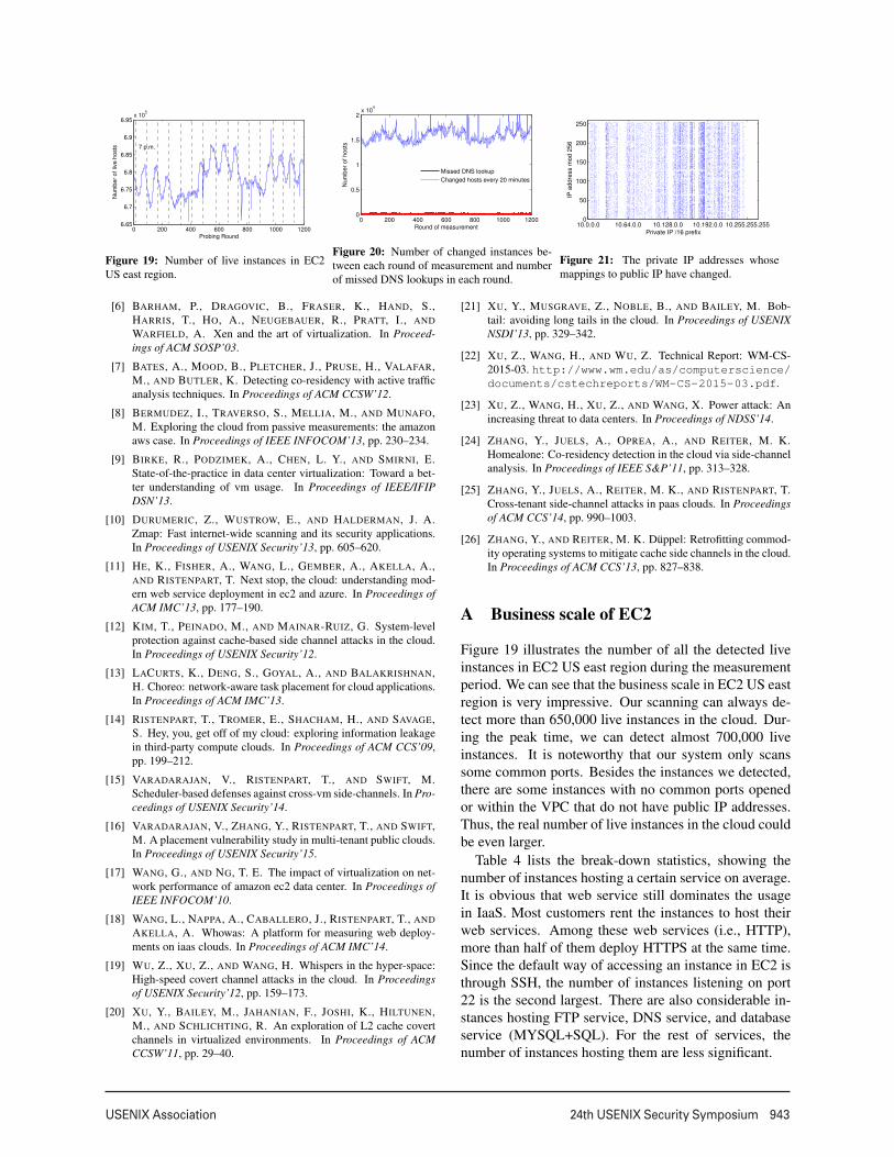
Figure 19: Number of live instances in EC2US east region.
0 200 400 600 800 1000 12000
0.5
1
1.5
2x 10
4
Round of measurement
Nu
mb
er
of
ho
sts
Missed DNS lookup
Changed hosts every 20 minutes
Figure 20: Number of changed instances be-tween each round of measurement and numberof missed DNS lookups in each round.
10.0.0.0 10.64.0.0 10.128.0.0 10.192.0.0 10.255.255.2550
50
100
150
200
250
Private IP /16 prefix
IP a
dd
ress m
od
25
6
Figure 21: The private IP addresses whosemappings to public IP have changed.
[6] BARHAM, P., DRAGOVIC, B., FRASER, K., HAND, S.,HARRIS, T., HO, A., NEUGEBAUER, R., PRATT, I., ANDWARFIELD, A. Xen and the art of virtualization. In Proceed-ings of ACM SOSP’03.
[7] BATES, A., MOOD, B., PLETCHER, J., PRUSE, H., VALAFAR,M., AND BUTLER, K. Detecting co-residency with active trafficanalysis techniques. In Proceedings of ACM CCSW’12.
[8] BERMUDEZ, I., TRAVERSO, S., MELLIA, M., AND MUNAFO,M. Exploring the cloud from passive measurements: the amazonaws case. In Proceedings of IEEE INFOCOM’13, pp. 230–234.
[9] BIRKE, R., PODZIMEK, A., CHEN, L. Y., AND SMIRNI, E.State-of-the-practice in data center virtualization: Toward a bet-ter understanding of vm usage. In Proceedings of IEEE/IFIPDSN’13.
[10] DURUMERIC, Z., WUSTROW, E., AND HALDERMAN, J. A.Zmap: Fast internet-wide scanning and its security applications.In Proceedings of USENIX Security’13, pp. 605–620.
[11] HE, K., FISHER, A., WANG, L., GEMBER, A., AKELLA, A.,AND RISTENPART, T. Next stop, the cloud: understanding mod-ern web service deployment in ec2 and azure. In Proceedings ofACM IMC’13, pp. 177–190.
[12] KIM, T., PEINADO, M., AND MAINAR-RUIZ, G. System-levelprotection against cache-based side channel attacks in the cloud.In Proceedings of USENIX Security’12.
[13] LACURTS, K., DENG, S., GOYAL, A., AND BALAKRISHNAN,H. Choreo: network-aware task placement for cloud applications.In Proceedings of ACM IMC’13.
[14] RISTENPART, T., TROMER, E., SHACHAM, H., AND SAVAGE,S. Hey, you, get off of my cloud: exploring information leakagein third-party compute clouds. In Proceedings of ACM CCS’09,pp. 199–212.
[15] VARADARAJAN, V., RISTENPART, T., AND SWIFT, M.Scheduler-based defenses against cross-vm side-channels. In Pro-ceedings of USENIX Security’14.
[16] VARADARAJAN, V., ZHANG, Y., RISTENPART, T., AND SWIFT,M. A placement vulnerability study in multi-tenant public clouds.In Proceedings of USENIX Security’15.
[17] WANG, G., AND NG, T. E. The impact of virtualization on net-work performance of amazon ec2 data center. In Proceedings ofIEEE INFOCOM’10.
[18] WANG, L., NAPPA, A., CABALLERO, J., RISTENPART, T., ANDAKELLA, A. Whowas: A platform for measuring web deploy-ments on iaas clouds. In Proceedings of ACM IMC’14.
[19] WU, Z., XU, Z., AND WANG, H. Whispers in the hyper-space:High-speed covert channel attacks in the cloud. In Proceedingsof USENIX Security’12, pp. 159–173.
[20] XU, Y., BAILEY, M., JAHANIAN, F., JOSHI, K., HILTUNEN,M., AND SCHLICHTING, R. An exploration of L2 cache covertchannels in virtualized environments. In Proceedings of ACMCCSW’11, pp. 29–40.
[21] XU, Y., MUSGRAVE, Z., NOBLE, B., AND BAILEY, M. Bob-tail: avoiding long tails in the cloud. In Proceedings of USENIXNSDI’13, pp. 329–342.
[22] XU, Z., WANG, H., AND WU, Z. Technical Report: WM-CS-2015-03. http://www.wm.edu/as/computerscience/documents/cstechreports/WM-CS-2015-03.pdf.
[23] XU, Z., WANG, H., XU, Z., AND WANG, X. Power attack: Anincreasing threat to data centers. In Proceedings of NDSS’14.
[24] ZHANG, Y., JUELS, A., OPREA, A., AND REITER, M. K.Homealone: Co-residency detection in the cloud via side-channelanalysis. In Proceedings of IEEE S&P’11, pp. 313–328.
[25] ZHANG, Y., JUELS, A., REITER, M. K., AND RISTENPART, T.Cross-tenant side-channel attacks in paas clouds. In Proceedingsof ACM CCS’14, pp. 990–1003.
[26] ZHANG, Y., AND REITER, M. K. Duppel: Retrofitting commod-ity operating systems to mitigate cache side channels in the cloud.In Proceedings of ACM CCS’13, pp. 827–838.
A Business scale of EC2
Figure 19 illustrates the number of all the detected liveinstances in EC2 US east region during the measurementperiod. We can see that the business scale in EC2 US eastregion is very impressive. Our scanning can always de-tect more than 650,000 live instances in the cloud. Dur-ing the peak time, we can detect almost 700,000 liveinstances. It is noteworthy that our system only scanssome common ports. Besides the instances we detected,there are some instances with no common ports openedor within the VPC that do not have public IP addresses.Thus, the real number of live instances in the cloud couldbe even larger.
Table 4 lists the break-down statistics, showing thenumber of instances hosting a certain service on average.It is obvious that web service still dominates the usagein IaaS. Most customers rent the instances to host theirweb services. Among these web services (i.e., HTTP),more than half of them deploy HTTPS at the same time.Since the default way of accessing an instance in EC2 isthrough SSH, the number of instances listening on port22 is the second largest. There are also considerable in-stances hosting FTP service, DNS service, and databaseservice (MYSQL+SQL). For the rest of services, thenumber of instances hosting them are less significant.
15

944 24th USENIX Security Symposium USENIX Association
Table 4: Number of instances hosting a certain service
FTP SSH Telnet SMTP WHOIS DNS DHCP Finger HTTP SQL HTTPS MYSQLLive in-stances 24,962 327,294 350 18,376 305 3,392 15 68 441,499 48 261,446 25,872
10.0.0.0 10.64.0.0 10.128.0.0 10.192.0.0 10.255.0.00
50
100
150
200
255
Internal IP address
IP a
dd
ress m
od
25
6
t1.micro m1.small m1.medium m3.medium m3.large
Figure 22: The distribution of internal IP addresses of instances with dif-ferent types in availability zone us-east-1a.
10.0.0.0 10.64.0.0 10.128.0.0 10.192.0.0 10.255.0.00
50
100
150
200
255
Internal IP address
IP a
ddre
ss m
od 2
56
us−east−1a us−east−1b us−east−1d
Figure 23: The distribution of internal IP addresses of instances in differ-ent availability zones.
B Dynamic environment of EC2
Our measurement can also reflect the dynamic environ-ment of EC2 to some extent. First, as shown in Figure 19,the number of live instances varies over time within a day.We observed a similar pattern each day: the peak time isaround 5 p.m. (EST) while the service reaches a valleyaround 4 a.m. (EST). Despite this diurnal pattern, thedifference in the number of live instances between peakand valley is not as significant as we expected. There areonly 1,000 more live instances at peak than valley, whichis relatively small considering the overall 650,000 live in-stances. The diurnal pattern is reasonable, as 4 a.m. ESTis very early morning for the US east coast and it is alsomidnight for the US west coast. It is intuitive that at thistime period fewer users are using EC2. The small differ-ence between peak and valley can be explained from twoaspects. First, most instances run stable services such asweb and database services. These instances remain activeall the time. Second, although the data center is locatedin the US, the customers are distributed all around theworld. For instance, Bermudez et al. [8] demonstratedthat the Virginia data center is responsible for more than85% of EC2 traffic in Italy. The time of 4 a.m. on theUS east coast is 10 a.m. in Italy when customers are veryactive there.
We are also interested in how dynamic the cloud en-vironment is. Figure 20 illustrates how many instancesare shutdown, newly booted, or re-located between eachround of measurement. We can see there are more than15,000 hosts that are changed every 20 minutes, indicat-ing that EC2 is a very dynamic environment with tens ofVMs booted and shut down every second.
Besides the dynamics of live instances, we are also in-terested in the networking dynamics. During our mea-surement, we observed overall 975,032 distinct privateIP addresses and 1,024,589 distinct public IP addresses.We recorded all the mappings from public IP to private IPand the mappings from private IP to public IP during our
measurement. We also recorded the mappings that arechanged during the measurement period. Over the courseof our 15-day measurement, 103,242 mappings changed.This implies that EC2 has likely recruited dynamic NATfor address translation.
Figure 21 shows the private IP addresses that are in-cluded in the changed mappings. It is clear that the IPaddress pool in the cloud is dynamic as well. The den-sity of the IPs in a certain range is significantly higherthan other areas. This range of private IPs are mostlyassigned to micro and small instances. Since micro andsmall instances are usually used for temporary purposes,ON/OFF operations on them are more frequent, leadingto more frequent changes in private-public IP mappings.
C VM placement locality in EC2
To investigate the VM placement locality in EC2, welaunched numerous instances with different types and indifferent availability zones to study whether the type orzone will impact the physical location of an instance.
Figure 22 illustrates the private IP distribution of somesample instances with different types in zone us-east-1a.The IP distribution exhibits a certain type locality. Wecan see from the figure that the instances of the sametype tend to have closer internal IPs, i.e., they are morelikely to be placed physically close to one another. How-ever, compared with corresponding results in 2008 [14],we can see that such type locality has been significantlyweakened.
We also study how availability zone could affect VMplacement. Figure 23 illustrates the internal IP distribu-tion of instances in different availability zones. As wecan see, VM placement still has availability zone local-ity, i.e., instances in the same zone are more likely tohave their internal IP addresses located within a certainrange. However, such locality is also much weaker thanin 2008 [14].
16