a mathematical force and moment model of a uh-1h … · 2013-08-31 · helicopter for flight...
TRANSCRIPT

NASA TECHNICAL MEMORANDUM
i l- a
A MATHEMATICAL FORCE AND MOMENT MODEL OF A UH-1H
HELICOPTER FOR FLIGHT DYNAMICS SIMULATIONS
Peter D. Talbot and Lloyd D. Corliss
Ames Research Center, NASA
and
Ames Directorate, USAAMRDL, AVRADCOM Ames Research Center Moffett Field, Calif. 94035
NASA TM-73,254 (Rcvis ed 8 ,' 30 / 7 8 )
June 1977
https://ntrs.nasa.gov/search.jsp?R=19770024231 2020-05-08T17:55:51+00:00Z

NOTATION
a
a 0
a1 9%
a lsSbls
a
A
1 s w
A X , Y , Z
A1 c
A1 C L
A1 s
Ai CB
CP
1 sw b
B I C
B I C L
BICP
BIS
B I C B
c 6 , c7
main r o t o r 1 i f . t curve s l o p e , p e r r a d i a n
main r o t o r coning, r a d
f i r s t harmonic va lues of main r o t o r b l a d e f l a p p i n g wi th r e s p e c t t o c o n t r o l a x i s , r ad
f i r s t harmonic va lues of main r o t o r b l a d e f l a p p i n g w i t h r e s p e c t t o s h a f t a x i s , r a d
l o n g i t u d i n a l component of c o n t r o l a x i s p o s i t i o n , r a d
r o t o r d i s k area, nR2, f t 2 , m2
body axis a c c e l e r a t i o n s , f t / s e c 2 , m/sec2
l a t e r a l swashplate c o n t r o l i n p u t , r ad
l a t e r a l c y c l i c p i t c h c o n t r i b u t i o n of s t a b i l i z e r b a r , r a d
l a t e r a l swashplate c o n t r o l b i a s r i g g i n g term, r ad
l a t e r a l p i l o t c o n t r o l i n p u t , r a d
l a t e ra l c o n t r o l a x i s command p o s i t i o n wi th r e s p e c t t o s h a f t , rad
l a t e ra l component of c o n t r o l a x i s p o s i t i o n , r a d
l o n g i t u d i n a l swashpla te c o n t r o l i n p u t , r a d
l o n g i t u d i n a l c y c l i c p i t c h c o n t r i b u t i o n of s t a b i l i z e r b a r , r a d
l o n g i t u d i n a l swashplate c o n t r o l b i a s r i g g i n g t e r m , r a d
l o n g i t u d i n a l p i l o t c o n t r o l i n p u t , r ad
l o n g i t u d i n a l c o n t r o l axis command p o s i t i o n w i t h r e s p e c t t o s h a f t , r a d
c o n s t a n t s i n l i nkage equa t ions , c y c l i c s t i c k t o swashpla te motion, r a d / i n . , rad/cm
cons tan t i n l inkage equa t ion , c o l l e c t i v e p i t c h t o c o l l e c t i v e s t i c k motion, r a d / i n . , rad/cm
c o n s t a n t s i n l i nkage equa t ion , t a i l r o t o r c o l l e c t i v e p i t c h t o peda l motion, r a d / i n . , rad/cm
i

f e , f e , f e 1 2 3
F 1
G1
i
h~~
H
main r o t o r d iameter , f t , m
c o n s t a n t s i n f u s e l a g e drag f o r c e e q u a t i o n s , l b / ( f t / s e c ) 2 , N/ (m/sec> 2
drag areas of f u s e l a g e , f t 2 , m2
v e r t i c a l f i n drag c o n s t a n t , l b / ( f t / s e c ) 2 , N / ( m / . ~ e c > ~
cons tan t used i n ground e f f e c t computation
h e l i c o p t e r rate of climb
h e i g h t of t a i l r o t o r above c . g . , f t , m
r o t o r H-force i n c o n t r o l axis - wind system, l b , N
c o n s t a n t s i n h o r i z o n t a l s t a b i l i z e r aerodynamic f o r c e s , l b / ( f t / s e c I 2 , N/(m/sec)2
I , I , I i n e r t i a s i n body axis I X X , yy zz xz
k, * k2 c o n s t a n t s i n v e r t i c a l f i n aerodynamic f o r c e s , l b / ( f t / s e c ) 2 , N / (m/sec>2
numerator t e r m , combining l i n k a g e and damping c o n s t a n t s , of s t a b i l i z e r b a r input t o c y c l i c p i t c h , sec 53
c o n s t a n t i n X equat ion r e p r e s e n t i n g ground e f f e c t
w a t e r l i n e displacement of r o t o r hub from a i r c r a f t c e n t e r of
KG
‘H g r a v i t y , f t , m
‘HS l o n g i t u d i n a l displacement of h o r i z o n t a l s t a b i l i z e r
aerodynamic c e n t e r from a i r c r a f t c e n t e r of g r a v i t y , f t , m
l o n g i t u d i n a l displacement of t a i l r o t o r hub from a i r c r a f t c e n t e r of g r a v i t y , f t , m ‘TR
w a t e r l i n e displacement of v e r t i c a l f i n aerodynamic c e n t e r from a i r c r a f t c e n t e r of g r a v i t y , f t , m ‘VF
cons tan t i n f u s e l a g e aerodynamic f o r c e c o n t r i b u t i o n , l b / ( f t / s e c ) 2 , N / (m/sec>2 ,
L1
body a x i s r o l l i n g moment, due t o main r o t o r , f t - l b , J
body a x i s r o l l i n g moment, due t o t a i l r o t o r , f t - l b , J
LR
L~~
,
M 1
cons tan t i n f u s e l a g e aerodynamic p i t c h i n g moment, f t - l b / (f t / s e c ) 2 , J / ( f t / s e c ) 2
ii
body a x i s p i t ch ing moment, due t o f u s e l a g e , f t - l b , J % body a x i s p i t ch ing moment, due t o h o r i z o n t a l s t a b i l i z e r ,
f t - l b , J
body a x i s p i t ch ing moment, due t o main r o t o r , f t - l b , J % N l cons tan t i n fuse lage aerodynamic yawing moment , f t - l b / ( f t / s e c ) ,
J/ (m/sec12
body a x i s yawing moment, due t o f u s e l a g e , f t - l b , J NF
NR
N~~
NVF
PB
PC
Q
qB
4C
B r
R
S
T
T~~
body a x i s yawing moment, due t o main r o t o r , f t - l b , J
body axis yawing moment, due t o t a i l r o t o r , f t - l b , J
body a x i s yawing moment, due t o v e r t i c a l f i n , f t - l b , J
body a x i s r o l l r a t e , r a d / s e c
main r o t o r s h a f t r o l l rate, wind-control a x i s system, r a d / s e c
main r o t o r to rque , f t - l b , J
body a x i s p i t c h r a t e , r a d / s e c
main r o t o r s h a f t p i t c h rate, wind-control a x i s system, r a d / s e c
body a x i s yaw r a t e , r a d / s e c
r o t o r r a d i u s , f t , m
c o n s t a n t s i n main r o t o r f o r c e equat ions , t a b l e 3
Laplace o p e r a t o r
area of aerodynamic s u r f a c e , f t 2 , m2
main r o t o r t h r u s t , lb, N
c o n s t a n t s i n ta i l r o t o r f o r c e equa t ions , t a b l e 3
t a i l r o t o r t h r u s t , l b , N
x-body a x i s relative v e l o c i t y , f t / s e c , m/sec
l o n g i t u d i n a l component of re la t ive wind i n wind c o n t r o l a x i s
B
C
U
system, f t / s e c , m/sec U
component of r e l a t i v e wind i n equa t ions f o r ve r t i ca l f i n aerodynamic force , f t l s e c , m/sec F U
iii
H U
B
C
V
V
F V
T
B
C
V
W
W
component of re la t ive wind i n equat ions f o r h o r i z o n t a l s t a b i l i z e r aerodynamic f o r c e , f t / s e c , m/sec
y-body a x i s re lat ive v e l o c i t y , f t / s e c , m/sec
l a t e r a l component of re la t ive wind i n wind-control axis system, f t / s e c , m/sec
component of re la t ive wind i n equat ions f o r v e r t i c a l f i n aerodynamic f o r c e , f t / s e c , m/sec
re la t ive wind normal t o p l ane of t a i l r o t o r , f t / s e c , m/sec
z-body a x i s r t r a t l v e v e l o c i t y , f t / s e c , m/sec
ver t ica l component of r e l a t i v e wind i n wind-control a x i s s y s t e m , f t / s e c , m/sec
xC
XF XR
c.g. X
Y
yC
yF
yR
'TR
'VF
Z
zc
zF
component of r e l a t i v e wind i n equat ions f o r h o r i z o n t a l s t a b i l i z e r aerodynamic f o r c e , f t l s e c , m/sec
main r o t o r f o r c e i n c o n t r o l a x i s system, l b , N
l o n g i t u d i n a l x-body f o r c e , due t o f u s e l a g e , l b , N
l o n g i t u d i n a l x-body f o r c e , due t o main r o t o r , l b , N
l o n g i t u d i n a l d i s t a n c e of a i rcraf t c e n t e r of g r a v i t y forward of main r o t o r s h a f t hub, f t , m
r o t o r Y-force i n wind c o n t r o l axis system, l b , N
cons t an t i n f u s e l a g e aerodynamic f o r c e c o n t r i b u t i o n , l b , N
main r o t o r f o r c e i n c o n t r o l a x i s system, l b , N
l a t e r a l y-body f o r c e , due t o f u s e l a g e , l b , N
l a t e r a l y-body f o r c e , due t o main r o t o r , l b , N
l a t e r a l y-body f o r c e due t o t a i l r o t o r , l b , N
l a t e r a l y-body f o r c e , due t o v e r t i c a l f i n , l b , N
r o t o r he igh t above ground p lane , f t , m
main r o t o r f o r c e i n c o n t r o l a x i s s y s t e m , l b , N
v e r t i c a l z-body f o r c e , due t o f u s e l a g e , l b , N
i v
zH
zR
F ci
HS ci
'm
Y
6
6 0 9 6 2
'1BY62B
a 6
6 C
e
P
6
6
6 S
0 e
'TR A
B
R
T
T
9
v e r t i c a l z-body fo rce , due t o h o r i z o n t a l s t a b i l i z e r , l b , N
v e r t i c a l z-body fo rce , due t o main r o t o r , l b , N
v e r t i c a l f i n angle of att&k'; rad
h o r i z o n t a l s t a b i l i z e r ang le of a t t a c k , r a d
maximum f l a p p i n g ampli tude of main r o t o r w i th r e s p e c t t o
aCR4 r o t o r Lock number f o r one b l ade , p - r o t o r mean b lade drag c o e f f i c i e n t
s h a f t , r a d
I B
c o n s t a n t s i n r o t o r d rag equat ion
s t a b i l i z e r ba r f l app ing c o n s t a n t s , r a d
p i l o t ' s l a t e r a l s t i c k displacement , i n . , cm
p i l o t ' s c o l l e c t i v e s t i c k d isp lacement , i n . , c m
p i l o t ' s l o n g i t u d i n a l s t i c k displacement , i n . , cm
p i l o t ' s peda l displacement , i n . , cm
h o r i z o n t a l s t a b i l i z e r i nc idence a n g l e , rad
a i r c r a f t p i t c h a t t i t u d e Euler ang le , deg, r a d
main r o t o r c o l l e c t i v e p i t c h
t a i l r o t o r c o l l e c t i v e p i t c h , rad
main r o t o r in f low r a t i o
main r o t o r advance r a t i o
sea leve l a i r dens i ty , s l u g s / f t 3 , kg/m3
r o t o r s o l i d i t y
s t a b i l i z e r b a r time c o n s t a n t , s e c
c o n t r o l a x i s response t i m e cons t an t , sec
a i r c r a f t r o l l a t t i t u d e , r ad
ampli tude of t o t a l c y c l i c p i t c h c o n t r o l i n p u t , r ad
phase angle of c y c l i c r i g g i n g , deg
V
phase (with r e s p e c t t o body a x i s ) of t o t a l c y c l i c p i t c h c o n t r o l i n p u t , r a d
I
1cI
n
S u b s c r i p t s
TR
VF
HS
IC
m
a i r c r a f t heading, r a d
r o t o r r a t i o n a l speed, r a d / s e c
t a i l r o t o r
v e r t i c a l f i n
h o r i z o n t a l s t a b i l i z e r
i n i t i a l c o n d i t i o n s - trimmed c o n d i t i o n s f o r t h e h e l i c o p t e r
model
v i

A MATHEMATICAL FORCE AND MOMENT MODEL OF A UH-1H
HELICOPTER FOR FLIGHT DYNAMICS SIMULATIONS
P e t e r D. Talbot and Lloyd D. C o r l i s s
Ames Research Center, NASA and
Ames Di rec to ra t e , USAAMRDL, AVRADCOM
SUMMARY
A model of a Bell UH-1H h e l i c o p t e r w a s developed t o suppor t s e v e r a l s imula t ions a t Ames Research Center and w a s used a l s o f o r development work on an a v i o n i c s system known as t h e V/STOLAND system a t Sperry F l i g h t Systems. This r e p o r t p r e s e n t s t h e complete equat ions and numerical v a l u e s of c o n s t a n t s used t o r e p r e s e n t t h e h e l i c o p t e r .
Responses t o s t e p i n p u t s of the c y c l i c and c o l l e c t i v e c o n t r o l s are shown and compared wi th f l i g h t test d a t a f o r a UH-1H. The model c o e f f i c i e n t s w e r e a d j u s t e d i n an a t t empt t o g e t a c o n s i s t e n t match wi th t h e f l i g h t t i m e h i s t o r i e s a t hover and 60 knots . F a i r l y good response matching w a s ob ta ined a t 60 kno t s , b u t t h e matching a t hover w a s no t as success fu l . P i l o t evalua- t i o n s of t h e model, bo th f i x e d and moving base , were made.
INTRODUCTION
The mathematical f o r c e and moment model descr ibed w a s developed t o s a t i s f y t h e need f o r r e p r e s e n t i n g t h e dynamics of a UH-1H h e l i c o p t e r f o r p i l o t e d s imula t ion . dynamics i n v e s t i g a t i o n s and f o r s imula t ion of terminal-area guidance and nav iga t ion t a s k s . It has been used i n s imula t ions f o r t h e development of so f tware f o r t h e nav iga t ion and guidance programs of an a v i o n i c s system known as V/STOLAND and f o r t h e i n v e s t i g a t i o n of t h e e f f e c t s of f a i l u r e s of s t a b i l i t y augmentation elements of t he c o n t r o l system (see r e f . 1).
The model w a s developed s p e c i f i c a l l y f o r u s e i n f l i g h t
The equat ions , r ep resen t ing the non l inea r c o n t r i b u t i o n s of t h e components of t h e h e l i c o p t e r t o the f o r c e and moments were assembled from many sources . The equa t ions are i n gene ra l form so t h a t changes can be made t o r e p r e s e n t h e l i c o p t e r s o the r t han t h e UH-1H. r o t o r r e p r e s e n t a t i o n , uniform inflow over t h e r o t o r d i s c , and s imple expres s ions f o r t h e c o n t r i b u t i o n s of t h e t a i l r o t o r , f u s e l a g e , and empennage. No i n t e r f e r e n c e e f f e c t s between components were modelled. I n t h e s imula t ion , the equa t ions were used i n a s tandard d i g i t a l program, p a r t i a l l y desc r ibed i n r e f e r e n c e 2 which i n c o r p o r a t e s t h e equa t ions of motion, v a r i a t i o n s i n t h e atmosphere, and r o u t i n e s f o r i n t e r f a c i n g wi th ana log equipment f o r
The model employs a q u a s i - s t a t i c main

d r i v i n g ins t ruments , p rovid ing c o n t r o l f o r c e s , e tc . S imula t ions have been conducted w i t h an EA1 8400 computer.
The model was eva lua ted by. comparing i t s response t o s t e p i n p u t s w i t h t h o s e obta ined i n f l i g h t on a UH-1H h e l i c o p t e r , and s u b j e c t i v e p i l o t assess- ments. s imula t ions .
The p i l o t e v a l u a t i o n s were obta ined dur ing both f i x e d and moving-base
HELICOPTER FORCE AND MOMENT EQUATIONS
The q u a s i - s t a t i c main r o t o r e q u a t i o n s were adapted from r e f e r e n c e 3 . The e q u a t i o n s f o r the aerodynamic f o r c e s of t h e f u s e l a g e and empennage were s e p a r a t e l y der ived , based e i t h e r on a v a i l a b l e wind t u n n e l d a t a of r e f e r e n c e 4 o r s tandard textbook wing theory , modified t o approximate s t a l l e d c o n d i t i o n s . An approximate r e p r e s e n t a t i o n f o r t h e t a i l r o t o r w a s d e r i v e d ; however, i n i t s o r i g i n a l form i t d i d n o t c o r r e c t l y p r e d i c t t a i l r o t o r damping. t h e e q u a t i o n s was r e t a i n e d w i t h a d j u s t e d c o n s t a n t v a l u e s used t o match t h e apparent t a i l r o t o r damping seen i n t h e f l i g h t t es t d a t a yaw responses .
The form of
The equat ions r e p r e s e n t aerodynamic f o r c e s and moments c o n t r i b u t e d by each component of t h e h e l i c o p t e r . The n e t r e s u l t s are t h r e e aerodynamic f o r c e s and t h r e e aerodynamic moments a p p l i e d i n a body-axis system. The o r i g i n of t h e body system is t h e h e l i c o p t e r c .g . frame w a s t a k e n t o be p a r a l l e l t o t h e main r o t o r s h a f t , p o s i t i v e d i r e c t i o n down, as i n f i g u r e 1.
The z axis of t h e r e f e r e n c e
The c o n s t a n t v a l u e s used f o r t h e c o e f f i c i e n t s i n t h e e q u a t i o n s are presented i n t ab l e s 1 and 2. It may b e noted t h a t t h e c h a r a c t e r i s t i c l e n g t h s used t o compute moments are based on d a t a r e f e r e n c e d t o t h e water- l i n e - b u t t l i n e - s t a t i o n system of t h e h e l i c o p t e r , r a t h e r than t h e axis system def ined above. S ince t h e UH-1H h a s a 5" forward mast t i l t , s l i g h t d i s c r e p - a n c i e s a re introduced by us ing r a w s t a t i o n and w a t e r l i n e v a l u e s t o l o c a t e components of t h e model. These are thought t o b e i n s i g n i f i c a n t .
Main Rotor Forces a t t h e Rotor Hub
a p ub - - 3 A u 2 ( 1 + 3 . 3 3 ~ ) - a. (+ - e) - RqqC ($ + G) 8
2

Main Rotor Torque
uAal w o b l +-I 3 - -
2
This expression was obtained from reference 5, equation (441, Po 195.
Flapping Coefficients
a = 0.048 0
( 4 )
Advance Ratio
Mean Blade Drag Coefficient
6 = 6 0 + 6,T2 (9)
Inflow Ratio
This expression is an implicit function and required an iterative solution in the computer program.
X = - R W 7 C - (p2 + ~ 2 1 1 1 2 KG (10)
3
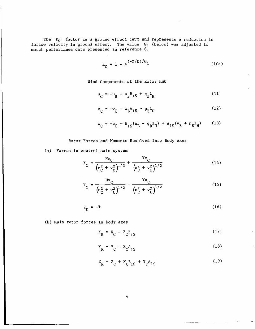
The KG f a c t o r is a ground e f f e c t t e r m and r e p r e s e n t s a r e d u c t i o n i n inf low v e l o c i t y i n ground e f f e c t . The va lue G, (below) '
match performance d a t a presented i n r e f e r e n c e 61
Wind Components a t t h e Rotor Hub
u = - u - w B C B B 1 s + ~ B ~ H
C B B 1s - PB'H v = - v - w A
was a d j u s t e d t o
( l o a )
w C = -WB + B ~ ~ ( U ~ - qBgH> + A ~ ~ ( v ~ + pBtH) (13:
Rotor Forces and Moments Resolved I n t o Body Axes
(a) Forces i n c o n t r o l ax is system
C Yv + HUC xc =
Zc = -T
(b) Main r o t o r f o r c e s i n body axes
XR = Xc - ZCBIS
Y R = Y c - Z A c 1s
Z R = Z c + X c B 1s + YCAIS
4

(c) Main r o t o r moments i n body axes
% - XRRH + R c.g.
NR = Q - YRXc
P i l o t t o Swashplate Cont ro l Equat ions
B = C16, 1 CP
I n t h i s form, no cross-coupling is shown corresponding t o c o n t r o l r i gg ing . I n t h e most gene ra l form,
AICp = C,6, cos 4p - (216, s i n 9,
BICp = C46, s i n 4p -k C16e COS $ J ~
For t h e UH-1H I # I ~ i s a c t u a l l y 5". For t h e s imula t ion @,= 0" w a s used.
, . Main and Tai l Rotor C o l l e c t i v e P i t c h
The f i r s t o r d e r l a g r e p r e s e n t a t i o n w a s used t o match more c l o s e l y t h e a a c c e l e r a t i o n d a t a obta ined from t h e f l i g h t t es t r e s u l t s .
2
S t a b i l i z e r Bar Trans fe r Funct ions
The B e l l s t ab i l izer b a r can be r ep resen ted by a s imple t r a n s f e r f u n c t i o n It which d e s c r i b e s i t s p a r a l l e l i npu t t o t h e c y c l i c p i t c h of t h e main r o t o r .
is c h a r a c t e r i z e d by a ga in KB and a t i m e c o n s t a n t , TB, which r e f l e c t
5

r e s p e c t i v e l y t h e mechanical mixing r a t i o and t h e mechanical damper charac te r - i s t i c of t h e shaft-mounted ba r .
p (SI -5
AICB(S) = -rBS + 1 B
The b a r has a pronounced e f f e c t on t h e s t a b i l i t y and t i c s of t h e h e l i c o p t e r . Values of t h e b a r c o n s t a n t s were t a t i o n w i t h B e l l H e l i c o p t e r Company.
Cont ro l I n p u t s t o Cycl ic P i t c h
c o n t r o l c h a r a c t e r i s - ob ta ined by consul-
The c o n t r o l i n p u t s t o t h e r o t o r c y c l i c p i t c h are represented as t h e sum of t h o s e due t o t h e p i l o t , s t a b i l i z e r bar and r i g g i n g of t h e c o n t r o l system.
( 3 1 ) - B i C - BICP + BICB + BICL
Rotor Control Axis Response t o Cycl ic P i t c h
I n t h i s r e p r e s e n t a t i o n , A I C and B I C are regarded as i n p u t s t o t h e r o t o r c y c l i c p i t c h . wi th a l a g r e l a t e d t o t h e r o t o r Lock number. The t e r m s A I S and B1S repre- s e n t t h e ins tan taneous o r i e n t a t i o n of t h e c o n t r o l a x i s w i t h r e s p e c t t o t h e f u s e l a g e body a x i s system ( i n t h i s case, t h e main r o t o r s h a f t a x i s ) .
The c o n t r o l a x i s of t h e h e l i c o p t e r is then allowed t o fo l low
AIC(S)
‘cRS + 1
I n s t e a d y s t a t e , B I S = B I C and A I S - - A I C ’
( 3 4 )
Thrus t T i s o r i e n t e d along t h e c o n t r o l a x i s and t h e H and Y f o r c e s are or thogonal t o T and each o t h e r . Forces H and Y may b e viewed approximately as components of t h e r o t o r f o r c e normal t o t h e t i p p a t h p lane a r i s i n g from r o t o r t i p p a t h p lane excurs ions from t h e commanded c o n t r o l a x i s
6

p o s i t i o n (as i n r e f . 7) o r as unique f o r c e s de r ived i n a c o n s i s t e n t wind- c o n t r o l a x i s system as i n r e fe rence 3. I n t h i s r e p r e s e n t a t i o n , r e f e r e n c e 3 w a s fol lowed. Equat ions 1 4 through 19 r e s o l v e t h e T , H and Y f o r c e s i n t o body axes.
Cont ro l Axis P i t c h and R o l l Rates
I n equat ions (1) through (7) t he t e r m s qc and pc are used t o denote p i t c h and r o l l rates of t h e c o n t r o l axis i n t h e c o n t r o l axis-wind system. They are r e l a t e d t o t h e body p i t c h and r o l l rates by t h e fo l lowing two equat ions :
T a i l Rotor Thrus t
where
e2 = leTR[ , eTR > 0.0873
e 2 = 0.0873 , eTR 5 0.0873
Due t o memory de r ived as an i s o l a t e d t a i l
l i m i t a t i o n s i n t h e computer, t h e s e equa t ions were o r i g i n a l l y economical approximation t o t h e t a i l r o t o r t h r u s t of an r o t o r . (The equat ions do n o t i n c o r p o r a t e t h e v o r t e x r i n g
o p e r a t i n g s t a t e of t h e t a i l r o t o r or f i n i n t e r f e r e n c e e f f e c t s . ) t h e main i n f l u e n c e s of in f low and c o l l e c t i v e p i t c h on t a i l r o t o r t h r u s t . It w a s found t h a t t h e d e r i v a t i o n on which t h e t a i l r o t o r damping c o n t r i b u t i o n t o N r . It w a s necessary , t h e r e f o r e , t o a d j u s t t h e cons t an t e m p i r i c a l l y t o match t h e f l i g h t test r e s u l t s .
They r e f l e c t
was based, g r o s s l y underpredic ted T,,
7

T a i l Rotor Con t r ibu t ion t o Body Forces and Moments
- 'TR - T~~
L~~ TR TR = Y h
NTR = -Y k TR TR
Fuselage Aerodynamics
N = - N v u F 1 B B
Vertical F i n Aerodynamics
u = u F B
B + ' V F ~ B v = -v F
s i n a = v /(uG + v;)1/2
= K V U + F v I v I
F F
'VF I F F 1 F F
YVF = k2u; + F v Iv I I F F
= - k u 2 + F v I V I 'VF 2 F 1 F F
NVF = -Y R VF VF
-20" 5 aF 5 20"
160" 5 aF 5 200"
20" < aF < 160'
200" < aF < 340"
8

Horizonta l S t a b i l i z e r Aerodynamics
( 5 4 ) A w = w + - + u 6 + k q H B R, B S H S B + " C
u = u ( 5 5 ) H B
The h o r i z o n t a l s t a b i l i z e r of t h e h e l i c o p t e r is connected t o t h e l o n g i t u d i n a l c y c l i c c o n t r o l and v a r i e s i n a non l inea r manner wi th l o n g i t u d i n a l c y c l i c s t i c k p o s i t i o n ( t a b l e 1 ) .
At t h e t i m e t h e s e equat ions were developed, d a t a f o r t h e UH-1H s t a b i l i z e r i nc idence schedule were n o t a v a i l a b l e . S ince t h e UH-1B s t a b i l i z e r is l inked i n a s i m i l a r manner to t h e c y c l i c c o n t r o l s , and t a b l e 1 v a l u e s were a v a i l a b l e , they were used i n l i e u of UH-1H va lues .
H W s i n aHS =
x B = x R + s (61)
YB = Y + Y + Y 4- YVF ( 6 2 )
z B = z + z + Z H (63)
R TR F
R F
The form of t h e equat ions f o r t h e f u s e l
T o t a l Body Forces and Moments
LB = LR + LTR
M B = % + % + %
NB = NR + NTR + N + NvF F
g e , h o r i z o n t a l s t a b i l i z e r nd v e r t i c a l f i n aerodynamics r e s u l t s from us ing t r igonomet r i c f u n c t i o n s t o approximate t h e l i f t and d rag curves i n wind axes , and then r e s o l v i n g t h e s e f o r c e s and r e l a t i v e wind i n t o body axes .

Estimation of Rotor F lapping w i t h Respect t o t h e S h a f t
The t i p path p lane o r i e n t a t i o n w i t h r e s p e c t t o t h e c o n t r o l a x i s i s r e p r e s e n t e d by t h e v a l u e s of t h e f l a p p i n g c o e f f i c i e n t s approximation t o t h e a c t u a l r o t o r f l a p p i n g a n g l e w i t h r e s p e c t t o t h e s h a f t a iS and blS, t h e fol lowing e q u a t i o n s were used. of t h e cyc l ic c o n t r o l i n p u t s
a l and b, . A s an
They r e f l e c t t h e i n f l u e n c e s A I C and B I C and t h e computed f l a p p i n g a m p l i -
convent ion of r e f e r e n c e 5 i s fol lowed. t u d e s a i and b l . The s i g n
bl s w a = a - 1s 1
b l s = b , + a 1 s w
a = 4, cos 4 1 s w t
4, = C O S - ~ ( C O S A I C c o s B ) 1c
t a n A
s i n B
The maximum f lapping ampli tude is g iven by
(72 )
where Bm The or thogonal components of f l a p p i n g i n t h e wind-shaft a x i s system are a l s and b ls , and phase of t h e c y c l i c i n p u t , r e s p e c t i v e l y .
is the maximum t e e t e r i n g a n g l e w i t h r e s p e c t t o t h e r o t o r mast.
4c and + t are t h e ampli tude of t h e c y c l i c i n p u t and t h e
COMPARISON OF HELICOPTER FLIGHT DYNAMICS WITH MATH MODEL DYNAMICS
A Bell UH-1H h e l i c o p t e r w a s instrumented and flown a t Crows Landing NAS November 12 , 1974 f o r t h e purpose o f o b t a i n i n g f l i g h t r e c o r d s a g a i n s t which t h e s i m u l a t o r model could be compared.
10

I n t h i s s e c t i o n , t h e he l i cop te r responses t o s t e p c o n t r o l i n p u t s are compared d i r e c t l y wi th t h e math model responses t o t h e same i n p u t s .
F l igh t Condi t ions
Two f l i g h t cond i t ions are shown: hover ou t of ground e f f e c t and 60 k n o t s level f l i g h t . no-wfnd cond i t ions . cond i t ions .
The f l i g h t tests were made a t nominally sea l e v e l The s imula to r model i s shown a t s t anda rd day, sea level
Control I n p u t s
S tep c o n t r o l i n p u t s of from k1.25 cm t o k2.5 cm (k1/2 i n . t o k 1 i n . ) were made i n c o l l e c t i v e , p i t c h , r o l l , and yaw c o n t r o l s . The p i l o t w a s i n s t r u c t e d t o e s t a b l i s h a s t eady f l i g h t cond i t ion (zero r a t e of c l imb, p i t c h , r o l l , and yaw) and then t o inpu t and hold t h e a p p r o p r i a t e c o n t r o l f o r as long a pe r iod as p o s s i b l e be fo re i n i t i a t i n g a recovery. These i n p u t s are simu- l a t e d as t r u e s t e p s i n t h e s imula tor t i m e h i s t o r y comparisons. Amplitudes f o r t h e s imula to r i n p u t s are adjus ted t o conform as c l o s e l y as p o s s i b l e t o t h e f l i g h t v a l u e s f o r l i n e a r displacements a t t h e p i l o t ' s hand o r f o o t .
Aircraft Conf igura t ion
The a i r c r a f t f lown, and t h e s imula tor model, r e p r e s e n t s a s t anda rd UH-1H (wi th s t a b i l i z e r b a r ) weighing 2800 kg (6158 l b ) . e s t ima ted i n i t i a l g ros s weight of t h e h e l i c o p t e r a t t h e commencement of t h e tests. a p r e - f l i g h t weight and ba lance of t h e h e l i c o p t e r , fol lowed by ad jus tments f o r f u e l burnoff and personnel t r a n s f e r s p r i o r t o t h e test runs .
This weight i s t h e
Both t h e weight and l o n g i t u d i n a l c e n t e r of g r a v i t y were de r ived from
The i n e r t i a v a l u e s used f o r the s imula to r model are r e p r e s e n t a t i v e va lues ob ta ined from unpublished B e l l Hel icopter Company da ta .
The ver t ical c e n t e r of g r a v i t y of t h e h e l i c o p t e r w a s no t known. The c h a r a c t e r i s t i c l e n g t h s used i n t h e model r e f l e c t on ly a reasonable estimate of i ts va lue .
Aircraft On-Board Sensors
The s e n s o r s on t h e a i r c r a f t were:
1. Body angu la r rate gyros sensing roll r a t e , p i t c h ra te and yaw rate,
2. Vertical gyro sens ing Euler a t t i t u d e s of t h e a i r c r a f t i n r o l l , p i t c h , and heading,
3 . Body acce lerometers measuring body axis a c c e l e r a t i o n s ,
11

4 . Airspeed i n d i c a t o r ,
5 . Ins tan taneous v e r t i c a l speed i n d i c a t o r (IVSI), i . e . , rate-of-climb p r e s s u r e instrument ,
6. Sensors f o r measuring c o n t r o l displacements a t t h e p i l o t ' s hand o r f o o t : 6, ( c o l l e c t i v e p i t c h s t i c k ) , 6, ( l o n g i t u d i n a l c y c l i c s t i c k ) , 6, ( l a t e r a l c y c l i c s t i c k ) , and 6 p (peda l , o r 8TR p i t c h i n p u t ) .
T i m e H i s t o r y Comparisons
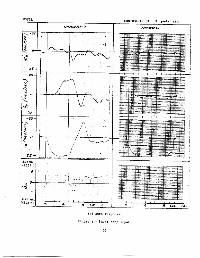
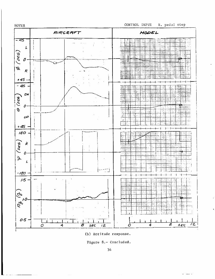
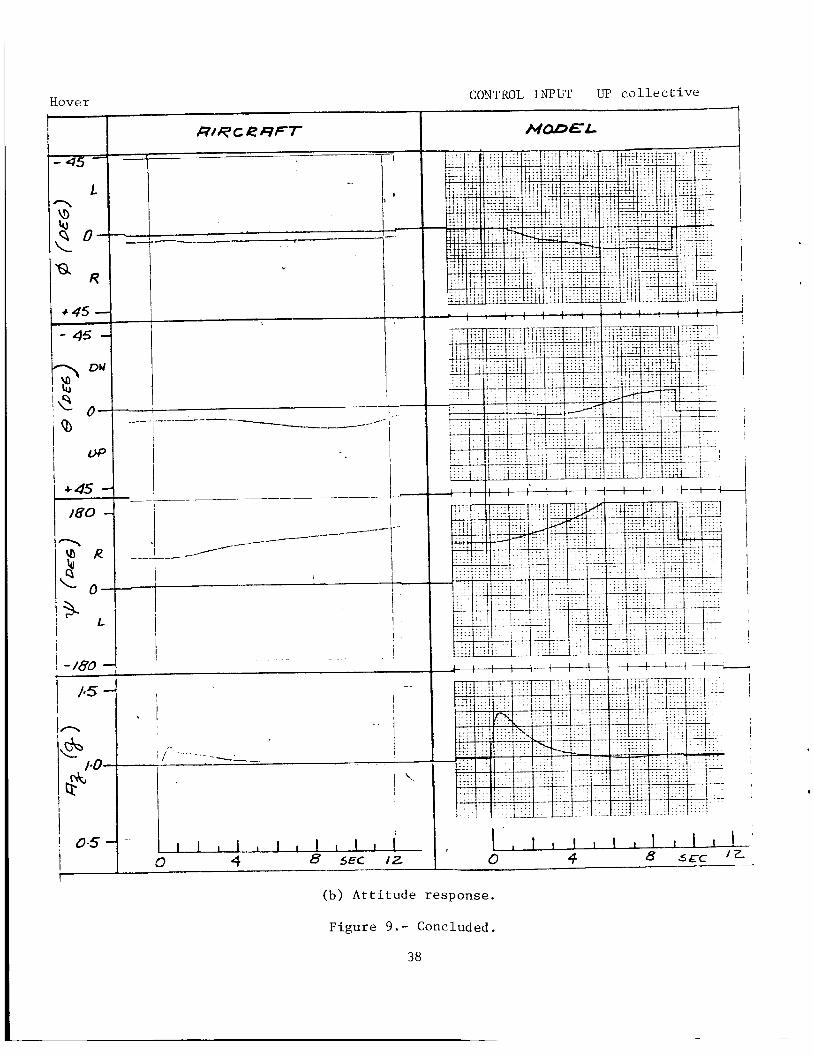
The a i r c r a f t and model angular ra te and a t t i t u d e responses t o t h e s t e p c o n t r o l i n p u t s a r e shown o p p o s i t e each o t h e r i n f i g u r e s 2 through 9 . Fig- u r e s 2 through 5 a re responses t o i n p u t s i n i t i a t e d from a s t e a d y 60 knot trimmed forward f l i g h t condi t ion . F igures 6 through 9 are responses t o i n p u t s s t a r t i n g from an i n i t i a l trimmed hover condi t ion .
The format f o r each f i g u r e i s t h e same. The f i r s t page c o n s i s t s of p ~ , qB and r B page. The second page shows t h e displacement a n g l e s 0, 8 and + and t h e ve r t i ca l a c c e l e r a t i o n A, f o r t h e same c o n t r o l i n p u t . Vert ical l i n e s on t h e f l i g h t d a t a denote t h e beginning and end of t h e c o n t r o l i n p u t . Tick marks on t h e model d a t a i n d i c a t e c o n t r o l i n p u t . A l l pens are zeroed a t t h e end of t h e c o n t r o l s t e p on t h e model d a t a .
versus t i m e f o r t h e c o n t r o l i n p u t shown a t t h e bottom of t h e
The a i rcraf t A, is included o n l y f o r a g e n e r a l t r e n d comparison s i n c e t h e f i l t e r i n g of t h i s s i g n a l was subsequent ly found t o be q u e s t i o n a b l e . The a i r c r a f t IVSI was suspec ted of having a l a r g e l a g s i n c e r a d a r h e i g h t p o s i t i o n data d i d n o t compare w e l l w i t h i n t e g r a t e d i n s t a n t a n e o u s v e r t i c a l speed i n d i - c a t o r (IVSI) readings. Consequently, a comparison of rate-of-climb response t o c o l l e c t i v e p i t c h i s n o t shown. Comparison w i t h r a d a r h e i g h t d a t a i n hover d i d show t h a t the rate-of-climb response i s a f i r s t o r d e r type of heave
response (h = Kh6c(l - e 'ITA)) and t h a t bo th t h e t i m e c o n s t a n t and s t e a d y s t a t e va lues were w e l l modeled by t h e equat ions .
-
A d i r e c t comparison of t h e r e c o r d s a t 60 k n o t s shows t h a t t h e primary responses t o t h e c o n t r o l i n p u t s are reasonably w e l l modeled: p i t c h ra te t o longi tudimal c y c l i c , r o l l rate t o la teral c y c l i c and yaw rate t o a p e d a l s t e p . The coupled responses t o t h e s e same s t e p s show s i g n d i f f e r e n c e s i n some cases, b u t t h e a b s o l u t e magnitudes of t h e responses are s m a l l . For t h e peda l s t e p and t h e c o l l e c t i v e s t e p , where t h e coupled responses are l a r g e r , t h e magni- t u d e s and s i g n s of t h e coupled responses appear t o be p r o p e r l y r e p r e s e n t e d .
Attempts t o d u p l i c a t e f l i g h t responses i n hover were n o t as s u c c e s s f u l . The primary responses are s u f f i c i e n t l y w e l l modeled so t h a t t h e p i l o t w a s g iven proper cues i n t h e f i r s t one t o two seconds fo l lowing a s e r v o f a i l u r e . The long term response i n p i t c h ra te i s exaggerated and t h e long term response i n r o l l rate i s underpredic ted by t h e model. p i t c h coupl ing i s e v i d e n t i n t h e f l i g h t r e c o r d s f o r b o t h t h e l a t e r a l s t e p
I n a d d i t i o n , s t r o n g
12
i npu t and t h e peda l s t e p i n p u t , a phenomenon not p r e s e n t i n t h e model. p h y s i c a l r eason f o r t h e s e coupled responses w a s no t understood.
The
The primary yaw ra te response i n hover i s good. The coupled yaw responses t o l a t e ra l c y c l i c p i t c h and t o c o l l e c t i v e p i t c h are s a t i s f a c t o r y .
The v a l i d a t i o n e f f o r t w a s stopped a t t h i s po in t because f u r t h e r a t t empt s t o improve t h e hover responses were n o t s u c c e s s f u l , o r i t changed t h e model adve r se ly a t 60 knots . Without more i n s i g h t i n t o t h e b a s i c aerodynamics of t h e a i r c r a f t i n hover , i t w a s a l s o d i f f i c u l t t o understand how t o al ter t h e equa t ions t o o b t a i n t h e d e s i r e d r e s u l t s ,
The i n i t i a l responses t o servo hardovers were be l i eved rea l i s t ic enough t o p rov ide t h e p i l o t w i th t h e appropr i a t e cues t o i n i t i a t e recovery. The o v e r a l l dynamics appeared t o be adequate t o g i v e a r easonab le estimate of a i r c r a f t excurs ions du r ing t h e recovery from a f a i l u r e .
P i l o t Evalua t ions
I n a d d i t i o n t o comparing t h e model w i t h f l i g h t t i m e h i s t o r i e s , t h e model w a s opera ted b o t h i n a f ixed-base s imula to r and i n a six-degree-of- freedom moving-base s imula to r ( 6 DOF). motion washout i n hover , and wi th motion washout a t 60 knots . The f l i g h t s wi thout washout w e r e made wi th open cab and wi th real outside-world r e f e r e n c e s . r e f e r e n c e provided by a t e r r a i n model.
The model w a s flown wi th and wi thout
The f l i g h t s w i th washout, and f i x e d base , were made w i t h v i s u a l
The model w a s judged t o be real is t ic a t 60 knots by t h e r e s e a r c h pilots who f l ew t h e s imula t ion . However, t he model w a s judged t o b e d i f f i c u l t t o f l y normally i n hover by every p i l o t who f lew i t . P r e c i s e hover and p r e c i s e maneuvers around hover a t low speeds , i nc lud ing qu ick s t o p s and la teral t r a n s l a t i o n s , were more d i f f i c u l t w i th t h e s imula ted model than wi th t h e a c t u a l h e l i c o p t e r . change t h e p i l o t ' s eva lua t ions .
Motion cues provided b y . t h e 6 DOF s imula to r d i d no t
I n s p i t e of t h i s , a l l p i l o t s were a b l e t o adapt themselves t o t h e s imula to r and f l y q u i t e p r e c i s e l y a f te r a l e a r n i n g pe r iod . i n t h e 6 DOF s imula to r wi th open cab and no motion washout w a s p o s s i b l e . I n a d d i t i o n t o t h i s , r e c o v e r i e s from r o l l and p i t c h s e r v o hardovers were accomplished, and a p r e c i s i o n hover r e e s t a b l i s h e d w i t h i n t h e 5.5 m2 of p o s s i b l e s imula to r travel.
P r e c i s i o n hover
This model was used i n a f l i g h t c o n t r o l s imula t ion desc r ibed i n r e f - e rence 1.
13
CONCLUDING REMARKS
The mathematical model 0 f . a UH-1H h e l i c o p t e r descr ibed i n t h i s r e p o r t w a s developed f o r rea l t i m e p i l o t e d s i m u l a t i o n . The model w a s eva lua ted by comparing i t s dynamics o b j e c t i v e l y w i t h f l i g h t test r e s u l t s and subjec- t i v e l y w i t h p i l o t e v a l u a t i o n s . The model appears t o b e s a t i s f a c t o r y f o r f l y i n g q u a l i t i e s i n v e s t i g a t i o n s a t forward speeds and u s a b l e , bu t less r e a l - i s t i c , f o r hover. The reasons f o r t h e d i s c r e p a n c i e s between f l i g h t and s i m u l a t i o n have n o t y e t been determined.
It i s be l ieved t h a t enough informat ion has been provided h e r e t o e n a b l e a p o t e n t i a l user t o d e c i d e whether t h e model i s s u i t a b l e f o r h i s a p p l i c a t i o n .
REFERENCES
1. C o r l i s s , Lloyd C . ; and Talbot , P . D . : A F a i l u r e E f f e c t s S imula t ion of a Low Authori ty F l i g h t Control Augmentation System on a UH-1H H e l i c o p t e r . NASA TM-73,258, 1977.
2. McFarland, R. F.: A Standard Kinematic Model f o r F l i g h t S imula t ion a t NASA-Ames. NASA CR-2497, 1975.
3. Seckel , Edward; and C u r t i s , H. C . , Jr.: Aerodynamic C h a r a c t e r i s t i c s of Hel icopter Rotors. Rotor C o n t r i b u t i o n s t o H e l i c o p t e r S t a b i l i t y Parameters. P r i n c e t o n U n i v e r s i t y Report , 1963.
4. Biggers , J. C . ; McCloud, 3. L . , 111; and P a t t e r a k i s , P e t e r : Wind Tunnel Tests of Two F u l l Scale H e l i c o p t e r Fuse lages . NASA TN D-1548, 1962.
5. Gessow, A . ; and Myers, G. C . , Jr . : Aerodynamics of t h e H e l i c o p t e r , Macmillan, 1952.
6. F lan igen and P o r t e r : Category I1 Performance Tests of t h e YUH-1D w i t h a 48-foot Rotor. AFFTC TDR 64-27, Nov. 1964.
7 . Wilcock, T . ; and Thorpe, A. C . : F l i g h t S imula t ion of a Wessex H e l i c o p t e r : A V a l i d a t i o n Exerc ise . RAE TR 73096, Sept . 1973.
8. McCloud, J. L . , 111; Biggers , J. C . ; and S t roub , R. H . : An I n v e s t i g a t i o n of F u l l Scale H e l i c o p t e r Rotors a t High Advance R a t i o s and Advancing Tip Mach Numbers. NASA TN D-4632, 1968.
9. F innes tead , R. L . ; and Graham, W. A , : T a i l Rotor Performance and T r a n s l a t i o n a l F l i g h t Handling Q u a l i t i e s Tests of t h e UH-1H H e l i c o p t e r . USAASTA Proj ect #71-18 , Jan. 1972.
14
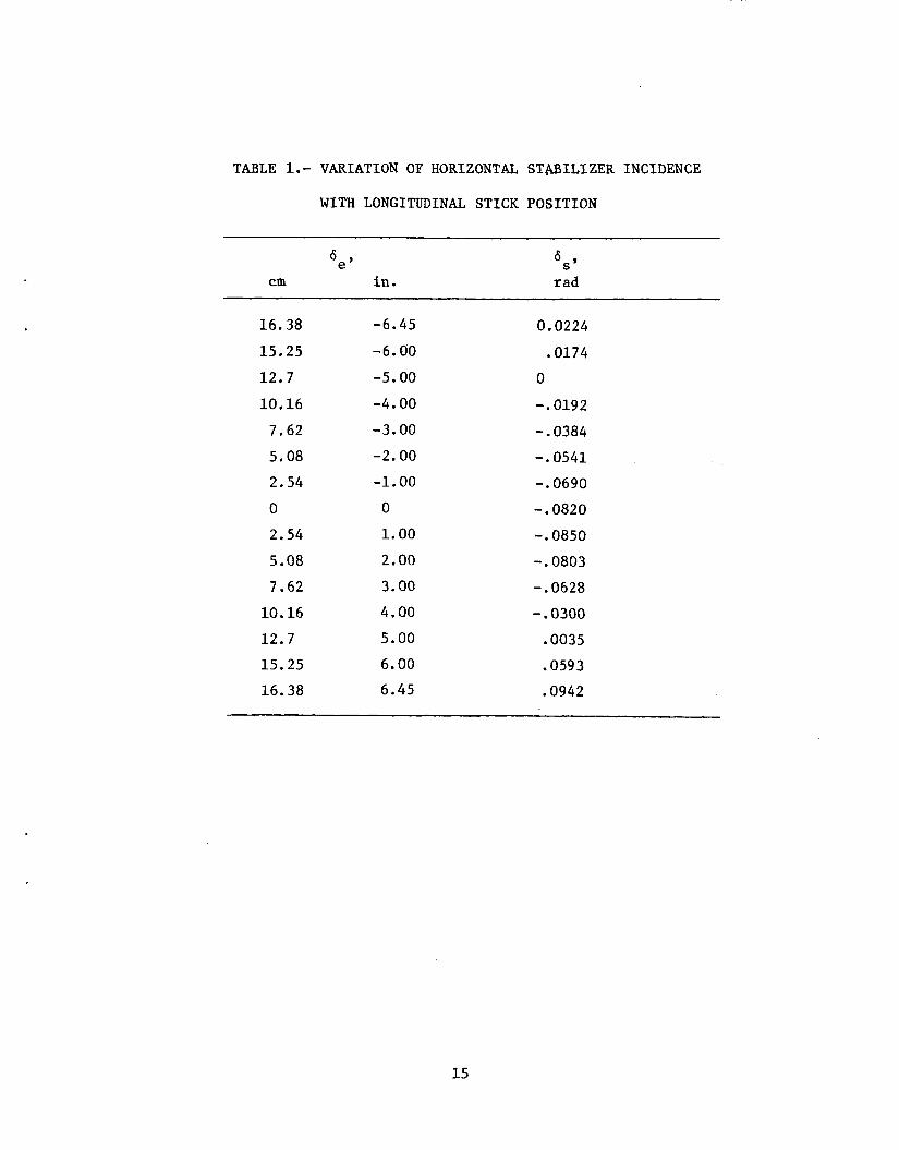
TABLE 1.- VARIATION OF HORIZONTAL STmILIZER INCIDENCE
WITH LONGITUDINAL STICK POSITION
6e CIU in.
6s rad
16.38
15.25
12.7
10.16
7.62
5.08
2.54
0
2.54
5.08
7.62
10.16
12.7
15.25
16.38
-6.45
-6.00
-5.00
-4.00
-3.00
-2.00
-1.00
0
1.00
2.00
3.00
4.00
5.00
6.00
6.45
0.0224
.0174
0
-. 0192
-. 0384
-. 0541
-. 0690
-. 0820
-. 0850
-. 0803
-. 0628
-. 0300
.0035
.0593
.0942
15
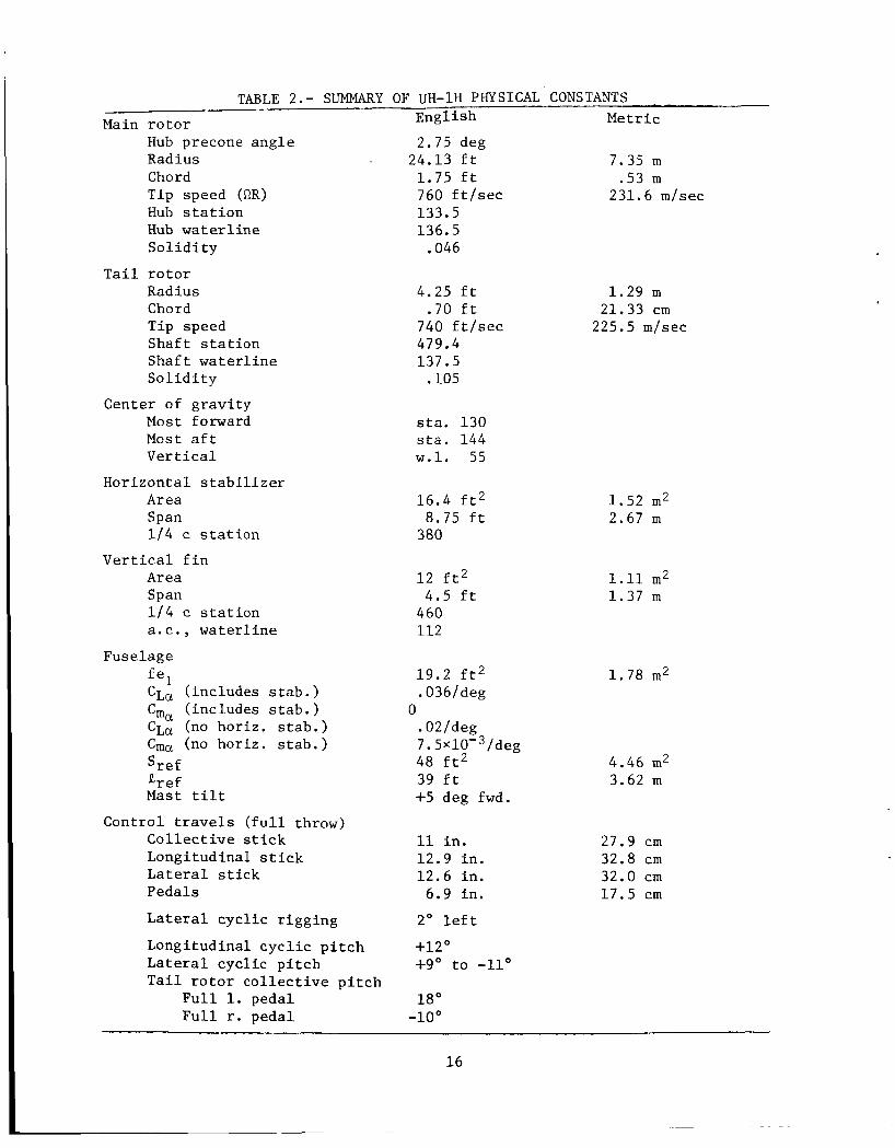
TABLE 2.- SUMMARY OF UH-1H PHYSICAL CONSTANTS Engl i sh Metric
2.75 deg 24.13 f t 7.35 m
1.75 f t .53 m 760 f t / s e c 231.6 m/sec 133.5 136.5
.046
Main r o t o r Hub precone a n g l e Radius Chord Tip speed (RR) Hub s t a t i o n Hub w a t e r l i n e S o l i d i t y
T a i l r o t o r Radius Chord Tip speed S h a f t s t a t i o n S h a f t w a t e r l i n e S o l i d i t y
Center of g r a v i t y Most forward Most a f t Vertical
H o r i z o n t a l s t a b i l i z e r Area Span 1 f 4 c s t a t i o n
Area Span 114 c s t a t i o n a. c . , w a t e r l i n e
Vertical f i n
Fuse lage
inc ludes s t a b . ) Cma ( inc ludes s t a b . ) C L ~ (no ho r i z . s t a b . ) Cma (no ho r i z . s t a b . ) S r ef g ref Mast t i l t
Cont ro l t ravels ( f u l l throw) C o l l e c t i v e s t i c k Longi tudinal s t i c k Lateral s t i c k Pedals
L a t e r a l c y c l i c r i g g i n g
Longi tudina l c y c l i c p i t c h Lateral c y c l i c p i t c h T a i l r o t o r c o l l e c t i v e p i t c h
F u l l 1. pedal F u l l r . p e d a l
fe1 CLa (
4.25 f t .70 f t
740 f t / s e c 479.4 137.5
,105
s ta . 130 s t a . 144 w . 1 . 55
16.4 f t 2 8 .75 f t
380
12 f t 2 4.5 f t
460 112
19 .2 f t 2 .036/deg
.02/deg 7 . 5 ~ 1 0 - ~ / d e g 48 f t 2 39 f t +5 deg fwd.
0
11 i n . 12.9 i n . 12.6 i n .
6.9 i n .
2' l e f t
+12' +go t o -11'
18 O
- loo
1.29 m 21.33 c m
225.5 m/sec
1.52 m2 2.67 m
1.11 m2 1 .37 m
1 .78 m2
4.46 m2 3.62 m
27.9 c m 32.8 c m 32.0 c m 17.5 c m
1 6

a, 1 rl (d 3
d u (d rl
7.1 m e3
a, u k 1 0 cn
c -4 M .rl k 0 \ c 0 *rl U
U c (d u 2 0 u
u .rl k
i
2 d rl M c w
z 0 rl X rl
h rl
Ln
5 Ln 0 rl X U 03
m
m
w 2
N n
v
d :IN
Q
d
p:
V a, m
m I 0 rl X h m h
V a, cn
m I 0 rl X h m h
m
w 2
C U \ rl
nl I 0 4 X 0 h
03
m
w a, p:
(d
hl \ rl
p:"
V a, cn
nl I 0 rl X m m e4
nl I 0 rl X \D m U
m
w a, Pi
(d
U \ rl
Ln p:
u al 111
* * I i
E 1 u a, m m I 0 rl X 0 0
U
U w \ u a, cn
m I 0 rl X hl hl
rl
m
w a, p:
p: C \ rl
co 0 rl X m m hl rl
P rl I U w
0 rl X h 0 rl
m
co
v)
w 2
p: n p: C
nl
W
<O
:IN Q
m p:
nl P rl \ rl d
d
I 2 .X. m 03
0 hl 0 03
rl
m
w 2
0 N rg W
a (d k
03 U 0
a (d k
03 e 0
03
w 2
cn (d
a a,
0 9 arb rl M C k ( d o a, c a , 0 1 u r l a,(d k ? a
C arb
w
2 2
0 (d
17

a 3 U . 2 N N m m . .
5 \ a (d Li co m 0 0
C .I4 \ a (d k
u) N 0
m
ru 2
W 0
c .rl
Li aJ a
5 u .rl a aJ 3 .rl u u a,& r l u rl .rl o u urn
E r- 0
N
U w m r- \I)
I I I
C 0 .rl u m l-i
.rl rn v) .I+
2
5 k 0 W
a a, u (d E T I u rn w
E m u)
a3
u w 0
U.2 N
m
W a, ";
u C (d U m
U
a
do
! rn 2
18
5 \ a m k
a3 N 0
I
d .I4 \ a (d k
rl r- 0
I
m
w aJ
0 u aJ
.rl u L) aJ rl rl 0 u c 0
k .rl o u u o O E k
rl r l a *rl a (d a , Bca
3
ID V
m k
m f-l rl
a cd k m rl rl
m
W
2
!-I 0
W
$ .rl u u aJ rl rl 0 L)

n n u u a J a J z p z p 5 5
IN Ihl hl n u aJ 0) \ E
W
N n u aJ
E z-?
W
m rl
m hl n u aJ
Prn r l \
U w W
N I 0 rl X U ln
\o
z z m 0 rl X rl
rl m
E z 1 U b rl cv
U w \ P rl
m U rl
. . .r)n a u r a m - a
U
d V m u
ra W E ! d s o B U
E's
I I I
f B
E 0 rl
N
U w 03 co \o
-rl U (d rl
.rl rn rn .rl
2
5 k 0 w a aJ U
2 *I4 U rn w
pc: w c
N m 0 m
N I n
hl N n n u u a J a J
rl \ 4 1 u u w w
n r n ~ r n
w w
V
r l \ U
: P rl
m 0 rl X 0
r- \D U \o
rn -rl J2 U
k 0 w
0 . U n
a c (d
i
r n . .rl w caJ w k
N
m aJ w a
0
dlN k
0 cn
6 U c (d U rn G 0 U
m n
d
4
19

n U a,
u w
el:
W
hl n U a, m \ E W
hl n U a, rn \
W E
N n U a, (I) \ a W
N n U a, m \
W E
N n
\
W W E
2 z z
0 * rl
oc, * rl
e o m *
b b
rl m m m r l r l a
a, 7 G .d u c 0 U
I
i3 H : H
rn
X 4
& D z H
w rn D c13
n
5 5: z 0 u Fri 0
1 rn
I
m w I4 m 2
IN
co N m r l c o r l o 0 0
I
N m N 0
\o rl 0
rl m 0
c U
c U u (d E 0
c U u z a,
U k 3 0 rn
(d u id a
0 0 u u
(d a u a l a
- cd
a u a l a u a u a
m 3 u - . 'r) 0) aa, c u
0 \
.rl u
0 0 m
0 0 m I1
Fri m (d cd
7 Cr w
II
a n u E Fri 0
rn
0 a N U
rn c X c d r n
0 n 0 0 N
V z H F 0
rn c (d u u 0
Q
x rl lN
&
X (v
x x3 24
20

aJ U & 7 0 m
c *ri M .a . . k 0 \ d 0 -r( u (d 1 m w
U c rd u (0 d - 0 u
hl
B M
Ad
m m b m
N u w
I M 7 rl m 0 0 W -4
k aJ U a 0 U .ri r l c d aJu x ( d
U 4 4 . a J 0 m u
X X
H
hl
' 7 M 3 0 m
m
G rl
hl u w
I M 7
I+
(0
0 0 a3
0 rl
h
(d u (d a
I . .r( 0 r l u aJ X k
aJ r l u !-la a J 0 m u
N N
H
N
7 M 3 u, 0 0 N
N U 1u
I M 7 rl v)
0 a3
rl
(d u (d a
I . .ri 0 4 v 01 X k
PI r l u r l a a J 0 m u
z W
21

Figure 1.
4 +XCG
L
XB
b
H U B FORCES AND MOMENTS T - ALONG CONTROL AXIS H - NORMAL TO CONTROL AXIS IN PLANE OF RELATIVE WIND
NORMAL TO T, H AND CONTROL AXIS
Y -
\ "I\ LA
Q ;> kT H U B + \4
1'1,
SHAFT AXIS
VIEW LOOKING AFT
NOTE: BODY Z AXIS IS PARALLEL TO MAIN ROTOR SHAFT
, - C h a r a c t e r i s t i c l e n g t h s and s i g n convent ions used f o r f o r c e s , moments and c o n t r o l displacements .
22
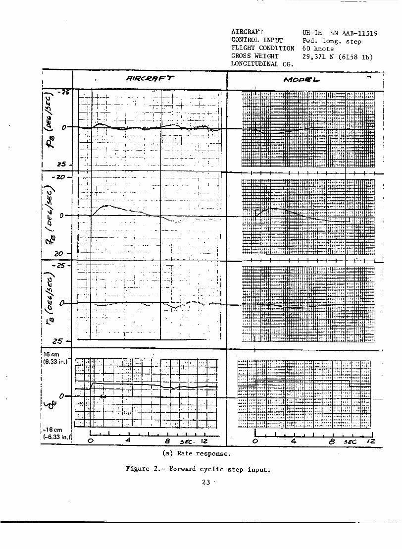
AIRCRAFT LJH-1H SN AAB-11519 CONTROL INPUT Fwd. long. s t e p FLIGHT CONDITION 60 knots GROS S WE I GHT LONGITUDINAL CG.
29,371 N (6158 lb) I
I - 8 '
i ! I MoncL
(a) Rate response .
F igu re 2.- Forward cycl ic s t e p i n p u t .
23 .

60 KNOTS CONTROL INPUT Fwd. long. s t e p
MW€L
e-
-
0 I . , t I 4 I I I t 8 I I scc t I / z l I
( b ) A t t i t u d e r e s p o n s e .
F i g u r e 2 . - C o n c l u d e d .
24

CONTROL INPUT L a t . cycl ic s t e p v
I I I MODEL f
(a> Rate response .
Figure 3 . - Lateral s t e p input .
25
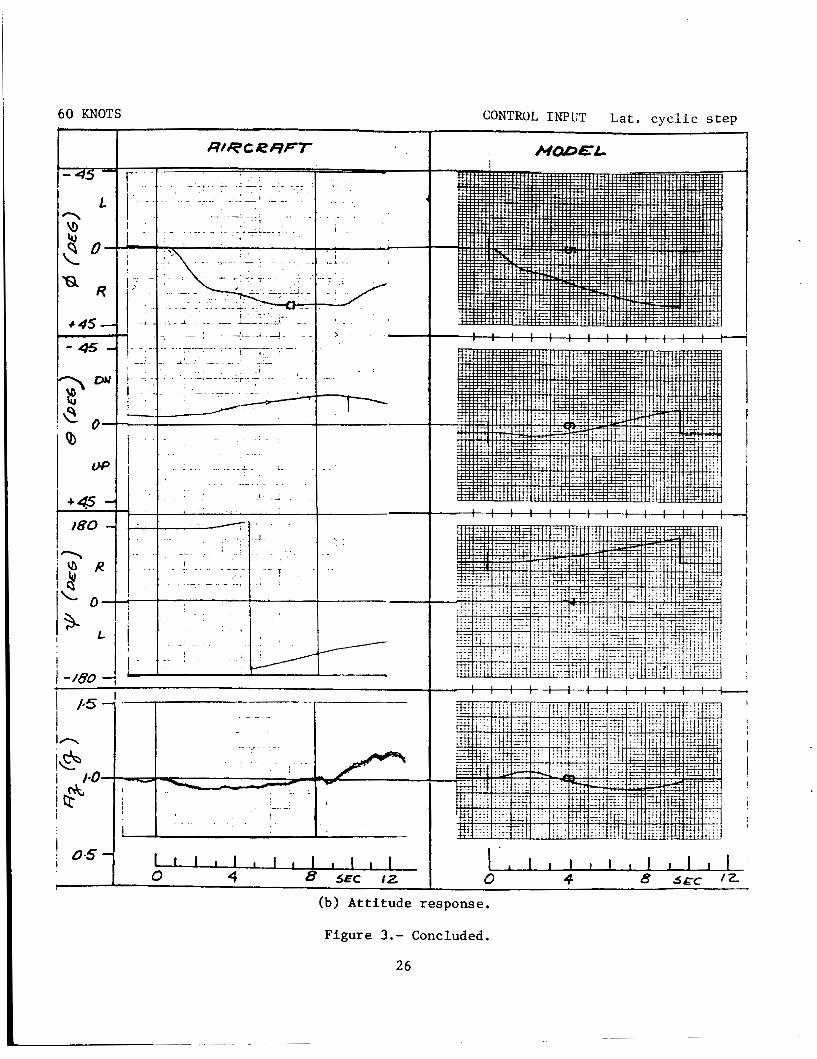
60 KNOTS CONTROL INPUT L a t . c y c l i c s t e p k
MODEL
I v ) I
I
i -180
I I - (b) A t t i t u d e response.
F igu re 3.- Concluded.
26
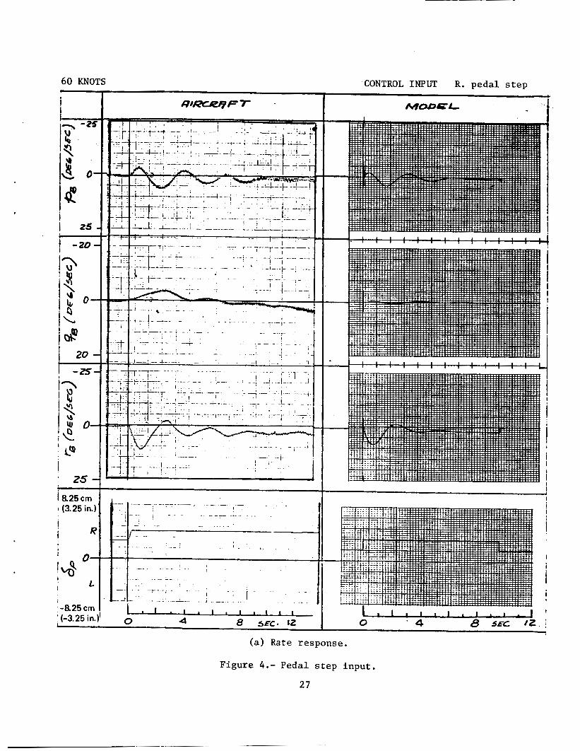
60 KNOTS CONTROL INPUT R. peda l s t e p w
i MODCL I I I
(a ) Rate response .
F igu re 4.- Pedal s t e p i n p u t .
27

60 KNOTS
Q R
I .s-
. -
I . .
I I
CONTROL INPUT R. p e d a l s t e p
MCWEL
I
(b) A t t i t u d e response.
Figure 4 . - Concluded.
28

60 KNOTS
I 25
I
i L!! i 2 5 -
0-
26.6cm (10.5 in.)
I . -.A
CONTROL INPUT UP c o l l e c t i v e
AqODCL
!
(a) Rate response.
F igure 5.- Col l ec t ive s t e p i n p u t .
29

60 KNOTS CONTROL INPUT U P c o l l e c t i v e
(b) A t t i t u d e response .
Figure 5.- Concluded.
30

. 25
- to
, 20 -
25 - 16 cm (6.33 in.).
0- 9Y
-16cm ,
(-6.33 in.)
-_
I
AIRCRAFT UH-1H SN AAB-11519 CONTROL INPUT Fwd. long. s t e p FLIGHT CONDITION Hover GROSS WEIGHT LONGITUDINAL CG.
29 ,371 N (6158 lb)
I I A q O D E t
(a) Rate response.
F igure 6 . - Forward c y c l i c s t e p i n p u t .
31

' - 4 5 - L - ' I
8 1; R
I * 4 5 -
- 45 - 3 D' ' 4 r
!e 0 0
I / 0--- - 1 7
c
--
/
------y-
1 / e 5 -I I
I - I I n I 1 I I
CONTROL INPUT Fwd. long,. s t e p
- 4 . - / , . . I I , I . . 8 , I , I I I
! . , ! I t-~! . ,. . .~., . _ ~ I ..+. . . . . , . . .
(b) A t t i t u d e response .
F igure 6 . - Concluded.
32

HOVER
I I
1 2 0 -
I p i I ! 2 5 - -1 5.9 crn (-6.25 in.) I
I L 1
I 0- I
R I w ! i lhacm 1(6.25 in.)' -
. I , . - . i I i t . . . . . . . . ..
! I 1 , , . . I ' I
CONTROL INPUT Lat . c y c l i c s t e p
AqODEL I
(a) Rate response.
F igure 7.- L a t e r a l c y c l i c s t e p inpu t .
33

- ~ ..- ' I
. I
/-- - I - - 180
I
CONTROL INPUT L a t . c y c l i c s t e p
MW€L
. (b) A t t i t u d e response.
F igu re 7.- Concluded.
34
HOVER - i -
-25
1 I 25 L 1 - 2 0 -
I 2 0 - I-zs-
8 2 5 cm ! (3.25 in.)
CONTROL INPUT R. pedal s t ep
I A?10DEL
(a) Rate response.
Figure 8 . - Pedal s t e p input.
35
HOVER CONTROL I N P U T R. peda l s t e p I I
(b) A t t i t u d e response .
F igu re 8.- Concluded.
36

.
HOVER Y
' i i 25
I
I ' -i- --____
- . . 1 - I
I I 1
I 4 8 src. IZ
26.6 cm (10.5 in.)
CONTROL INPUT UP c o l l e c t i v e
AqODEf-
-I I I I I I
! ! I i
I
0 1' B 5EC I2
(a) Rate response .
F igu re 9.- Collective s t e p i n p u t .
37
I
! ! I 1 -180 - -
I I
.
(b) A t t i t u d e response .
F i g u r e 9.- Concluded.
38

I . Report No. TM- 73 , 254
8. Performing Organization Report No. 7. Author(s1 A-7080 Peter D. Talbot and Lloyd D. C o r l i s s
10. Work Unit No.
505-10-23 9. Performing Organization Name and Address
3. Recipient's Catalog No. 2. Government Accession No.
Ames Research Center , NASA and Ames D i r e c t o r a t e , 11. Contract or Grant No. USAAMRDL, AVRADCOM, Ames Research Center
4. Title and Subtitle
A MATHEMATICAL FORCE AND MOMENT MODEL OF A UH-1H HELICOPTER FOR FLIGHT DYNAMICS SIMULATIONS
5. Report Date
6. Performing Organization Code
Moffe t t F i e l d , CA 94035 S nsorin Agency Name and Address
'kaflona? Aeronaut ics and Space Adminis t ra t ion
16. Abstract
13. Typa of Report and Period Covered Technica l Memorandum
A model of a B e l l UH-1H h e l i c o p t e r w a s developed t o suppor t s e v e r a l s imula t ions a t Ames Research Center and w a s used a l s o f o r development work on an a v i o n i c s system known as t h e V/STOLAND system a t Sper ry F l i g h t Systems. This r e p o r t p r e s e n t s t h e complete equat ions and numerical v a l u e s of c o n s t a n t s used t o r e p r e s e n t t h e h e l i c o p t e r .
Responses t o s t e p i n p u t s of t he c y c l i c and c o l l e c t i v e c o n t r o l s are shown and compared w i t h f l i g h t test d a t a f o r a UH-1H. a d j u s t e d i n an a t tempt t o g e t a c o n s i s t e n t match wi th t h e f l i g h t t i m e h i s t o r i e s a t hover and 60 knots . a t 60 kno t s , bu t t h e matching a t hover w a s no t as s u c c e s s f u l . e v a l u a t i o n s of t h e model, bo th f ixed and moving base , were made.
The model c o e f f i c i e n t s were
F a i r l y good response matching w a s ob ta ined P i l o t
Washington, D. C. RfiD Laboratory, Moffe t t F i e l d , CA 94035
20546 and U. S. Army A i r Mobi l i ty
17. Key Words (Suggested by Author(s1)
UH-lfi h e l i c o p t e r f l i g h t dynamics S imula t ion Fixed base and comparison with f l i g h t
test
14. Agency code
18. Distribution Statement
Unlimited
STAR Category - 08 ~ ~~
~
19. Security Classif. (of this report) 20. Security Classif. (of this pagel
U n c l a s s i f i e d Unclass i f ied
21. No. of Pages 22. Price'
45 $3.75