a mapping from shlaer-mellor to uml - ooatool.comooatool.com/docs/smuml99.pdf · a mapping from...
TRANSCRIPT

©Project Technology, Inc. 1999 ©Kennedy Carter Ltd. 1999 V1.0 September 1999 Page 1
A Mapping from Shlaer-Mellor to UML
Stephen J. [email protected]
Project Technology, Inc.7400 N. Oracle Rd, Suite 365
Tucson, Arizona 85704http://www.projtech.com
Kennedy Carter Ltd.14 The Pines, Broad Street
Guildford, Surrey, GU3 3BHhttp://www.kc.com
1. Background
The purpose of this paper is to present a mapping between Shlaer-Mellor concepts and theirrepresentations in UML. The objectives of this mapping are to:
• bring executable and translatable models to the UML community
• enable interchange between Shlaer-Mellor tools and UML tools
• bring the terminology as close as possible to UML so that the models “look like” UML
• introduce as little dissonance as possible for native Shlaer-Mellor users
The ideas presented here are the results of work that builds on the ideas presented in earlier papers[M14,M15]. These earlier papers established the basis for using the UML notation to represent Shlaer-Mellor models but did not examine many aspects of the formalism in any detail. In particular thejustification for the choices of mapping had not been fully established with respect to the UML meta-model. This issue is vitally important if it is to be possible to interchange models between tools whilepreserving their semantic content.
This latter issue is also becoming of greater importance to the wider UML community. In its current formUML is designed to support a wide variety of different modelling techniques and formalisms. This isevident, for example, in the state machine formalism which allows both Moore and Mealy formalism withhierarchical states including concurrent sub-states and both synchronous and asynchronous callingsemantics. The result of this is not only that almost any state modelling style can be supported but alsothat many combinations of elements have no defined execution semantic1. It is now widely recognisedwithin the UML community, however, that considerable benefit can be gained by forming subsets of theUML with well defined execution semantics. Such subsets can form an “executable UML” which would
1 These are termed “Semantic Variation Points” in the UML specification

©Project Technology, Inc. 1999 ©Kennedy Carter Ltd. 1999 V1.0 September 1999 Page 2
enable the simulation, execution, testing and ultimately translation of UML models into target code. Aspart of this movement, work is progressing under the auspices of the OMG towards the definition of“profiles” that define such subsets and towards the more detailed definition of the contents of “actions”including a more precise definition of the execution semantics of UML models.
This paper, then, describes an executable UML “profile”.
This paper presents a combined approach encompasing the various different flavours of the Shlaer-Mellormethod. Throughout this paper we will refer to the various flavours, which are described in more detailin section 11.
Finally, this work is not complete. Although all the elements of the Shlaer-Mellor method have beenenumerated and tentative mappings identified (see section 12), we have not yet fully established all theimplications. We welcome comments from the reader.
2. Principles
To make the mapping regular, we have to have a set of mapping principles that we can apply as uniformlyas possible throughout. We discuss below the use of names, stereotypes, and tags.
On Names. One purpose of this paper is to present a mapping between Shlaer-Mellor concepts and theirrepresentations in UML. To maintain complete and clear domain separation between two, it would bebest to maintain two entirely different vocabularies, which would yield statements of the form “Representa (Shlaer-Mellor) object as a box with three compartments… .” This mapping, then, is from the concept toits representation, an icon. However, the box-with-three-compartments represents a ‘class’ in UML, andusers of UML will always refer to the box-with-three-compartments as a class, for that is what it is.
The approach to naming taken in this paper is therefore as follows.
The notational mappings are generally presented as:
“Represent <Shlaer-Mellor concept> as <notational element>“
We name each notational element using UML terminology; (i.e. a ‘Box-with-several-compartments’ isreferred to as a ‘Class’). This reduces dissonance when reading a UML model based on the notationalelements under discussion. This also renders the use of this mapping in UML compliant tools morestraight forward.
However, for certain notational mappings (for example those that use the Package Diagram2) refering tothe UML representation simply by its representation type will be inadequate. For those situations we willuse the Shlaer-Mellor terminology.
2 We should not be surprised by this as the Package concept in UML is intended to be able to capture awide variety of different packaging concepts. It is inevitable that any use of packages in UML will haveto supply some method specific names.
©Project Technology, Inc. 1999 ©Kennedy Carter Ltd. 1999 V1.0 September 1999 Page 3
On Stereotypes. A stereotype in UML is a way of introducing a new class of modelling element within amodel. A stereotype can only specialize an existing class in the metamodel. A stereotype is shownbetween guillemets << and >>.
We use a stereotype to distinguish one use of a symbol from another, in a manner that extends the UMLmetamodel. For example, we shall use the package diagram to model both subsystems and domains.Because the UML makes no distinction between these two concepts and we use the same diagram for both,there must be a way to distinguish between them.
We also define a stereotype as high up in the model hierarchy as possible so that the stereotype appears asfew times as possible. For example, we can stereotype the a UML Class Diagram as a (Shlaer-Mellor)Class Model so that all attributes on that model are required to be atomic.
On Tags. Tags are used to add arbitrary information to the models, but not to extend the meta-model.Tags are represented as a comma-delimited sequence of specifications, surrounded by braces {}. Eachspecification may be simply a keyword (a tag), or a keyword with a value (a property), expressed askeyword = value. Keywords and values are simply strings.
We use tags to add information about a model element in a manner that does not extend the metamodel ofUML. For example, we shall use a tag to indicate mathematically dependent attributes.
Often, we use tags to represent Shlaer-Mellor concepts such as Numbers and Key Letters. These arepresent in Shlaer-Mellor to aid readability and to support model management. As such they are notcentral to the formalism itself and may be omitted from diagrams if desired. In this paper we will alwaysshow such tags in order to demonstrate what they look like if present.
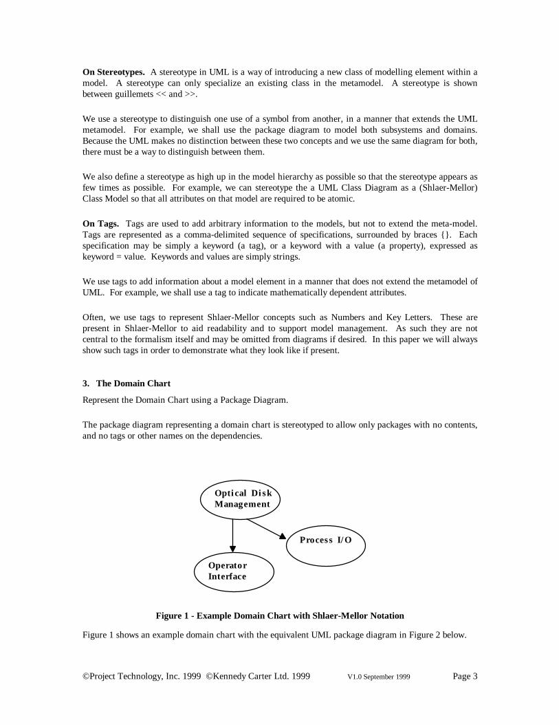
3. The Domain Chart
Represent the Domain Chart using a Package Diagram.
The package diagram representing a domain chart is stereotyped to allow only packages with no contents,and no tags or other names on the dependencies.
Opti cal Di skManagement
Process I/ O
OperatorInterface
Figure 1 - Example Domain Chart with Shlaer-Mellor Notation
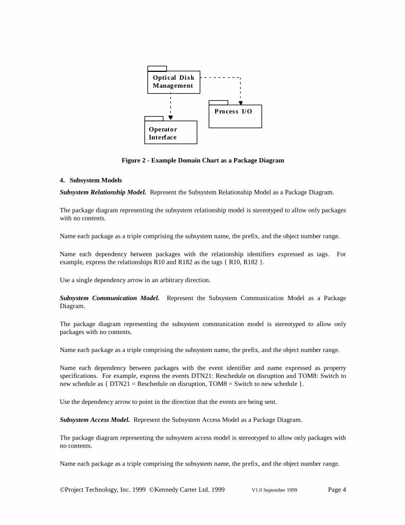
Figure 1 shows an example domain chart with the equivalent UML package diagram in Figure 2 below.
©Project Technology, Inc. 1999 ©Kennedy Carter Ltd. 1999 V1.0 September 1999 Page 4
Opti cal Di skManagement
Process I/O
OperatorInterface
Figure 2 - Example Domain Chart as a Package Diagram
4. Subsystem Models
Subsystem Relationship Model. Represent the Subsystem Relationship Model as a Package Diagram.
The package diagram representing the subsystem relationship model is stereotyped to allow only packageswith no contents.
Name each package as a triple comprising the subsystem name, the prefix, and the object number range.
Name each dependency between packages with the relationship identifiers expressed as tags. Forexample, express the relationships R10 and R182 as the tags { R10, R182 }.
Use a single dependency arrow in an arbitrary direction.
Subsystem Communication Model. Represent the Subsystem Communication Model as a PackageDiagram.
The package diagram representing the subsystem communication model is stereotyped to allow onlypackages with no contents.
Name each package as a triple comprising the subsystem name, the prefix, and the object number range.
Name each dependency between packages with the event identifier and name expressed as propertyspecifications. For example, express the events DTN21: Reschedule on disruption and TOM8: Switch tonew schedule as { DTN21 = Reschedule on disruption, TOM8 = Switch to new schedule }.
Use the dependency arrow to point in the direction that the events are being sent.
Subsystem Access Model. Represent the Subsystem Access Model as a Package Diagram.
The package diagram representing the subsystem access model is stereotyped to allow only packages withno contents.
Name each package as a triple comprising the subsystem name, the prefix, and the object number range.

©Project Technology, Inc. 1999 ©Kennedy Carter Ltd. 1999 V1.0 September 1999 Page 5
Name each dependency between packages with the process identifier expressed as tags. For example,express accesses to the processes DTC.2, DTZ.4 as { DTC.2, DTC.4 }.
Use the dependency arrow to point in the direction of the access.
5. Object Information Model
Represent the Shlaer-Mellor Information Model using a UML Class Diagram.
The class diagram representing the object information model has several stereotypes that apply to themodel as a whole and apply to each of the kinds of elements that may appear on the model. We describeeach stereotype below when we describe each kind of model element.
Objects. Represent a Shlaer-Mellor object using a UML Class. The class has three compartments:
• the name compartment, which contains the name comprising three parts, the object number,object name, and key letter
• the attribute compartment (see section below) and
• the operation compartment (see section below)
Represent an imported object using italics for the name, with a note reading “(from <subsystem name>)”
Attribute. Represent an attribute with its name, a colon, and its type. (See the subsection on typingbelow.)
We stereotype the class diagram that represents an object information model to require attributes to besingle valued.
Represent an identifying attribute with a tag { I=2 }, { I=2 }, { I=33 }… If an attribute participates inmultiple identifiers, the tags may be strung together as { I=1,2 } etc.
Represent a referential attribute with a tag corresponding to the relationship number(s) , i.e. { R=2,4 }
Represent a constrained referential attribute by extending the tag to have the letter ‘c,’ i.e. { R=2c }
Represent mathematically dependent attributes with a tag { M }.
Types. Represent the domain-specific data type as a string.
Separately, define the domain-specific data type in terms of its base types as defined in Data Types inOOA [M4] or the ASL Reference Manual [M10]

©Project Technology, Inc. 1999 ©Kennedy Carter Ltd. 1999 V1.0 September 1999 Page 6
Operations. Shlaer-Mellor does not show operations on the object information model. However, theUML class diagram does allow operations, and there are potential uses for them in Shlaer-Mellor OOA,such as data accessors, transformers or syncronous services3. Whether or not these are shown is optional.
Represent a read accessor as an operation with isQuery = true. Use the standard UML syntax for theoperation, i.e. OperationName( ParameterName : ParameterType = DefaultValue, … ) : ReturnType. Donot include the instance identifier.
Represent a write accessor as an operation.
Represent a (publicly accessible) transformer as an operation with the tag { Transform }
Represent a synchronous service as an operation with the OperatioName being the name of thesynchronous service. Do not include the key letter and service number as part of the name. These aremodelled as tags on the operation.
Relationships. Represent a relationship as a class association, with the multiplicity and conditionalityusing numbers as in UML (i.e. 1c à 0..1, M à 1..*)
Represent the relationship identifier (i.e. R2 or R4) as an association name. Use the same approach forrelationships constructed by composition: R3 = R2 + R4.
Represent the relationship roles names as association roles, such as ‘owns’ and ‘is owned by.’4
Associative Objects. Represent an associative object as an association class. Note that in the UML meta-models, the association and the association class are indistiguishable entities. This has the effect thatShlaer-Mellor “many-associative” relationships (e.g. M-(M:M) or M-(1:M) etc.) cannot be modelleddirectly in UML. Instead, for such situations analysts must create an additional class with a M:1association with the original association class.
Associative Objects with Assigners. Show an associative object with an assigner with a stereotype<<assigner>>.
Note that this stereotype can designate two classes expressed as one on the graphic. The name of the“base” class is as given by the user “5, Dog Adoption, DA” and the assigner is name “<null>, DogAdoption-A, DA-A”. This will allow us to build two state models in a UML repository.
Sub/Supertype Relationships. Represent a sub/supertype relation using the UML generalization relation.
3 According to method flavour. Note that we would not normally show “Event Taker” operations on theclass since these represent only one style of implementation of state machines. Other, different styles arepossible. We consider the State Machine to be a separate part of the formalism from the operations shownon the class diagram.
4 Note that the classic UML “style” (as used in the many books) is to use nouns as roles on associations.However, the UML standard does not dictate this and allows for the Shlaer-Mellor style verb phrases. Wemaintain that such verb phrases have many advantages over the noun style.

©Project Technology, Inc. 1999 ©Kennedy Carter Ltd. 1999 V1.0 September 1999 Page 7
We stereotype the class diagram to require the tag {complete, disjoint}. This information may beexpressed visually on a model at the tool vendor’s option.
Represent sub/supertype relationship numbers as tags {Rn}.
Note that in the UML, generalisation is not the same thing as inheritance. Rather, inheritance is a set ofmechanisms that can be applied to a generalisation hierarchy. Such an application is not, however,compulsory. Indeed, the UML specification makes it clear that using inheritance makes it difficult tomodel multiple classification and indicates that other approaches might be more appropriate in thiscontext. We suggest that the Shlaer-Mellor sub/supertype concept is such an approach. In the Shlaer-Mellor view of generalisation then, we think of the superclass as having instances (objects) that aredistinct from, but associated with the subclass instances.
1. Dog D
* Licence Number• Name• Breed• Weight• Owner (R3)
2. Dog Owner DO
* Name• Address
isownedbyowns
R3
Figure 3 - A section of a Shlaer-Mellor Information Model
The example information model fragment shown in Figure 3 will become the UML class diagramfragment shown in Figure 4.
Dog {no=1,kl=D}
Licence Number {I=1}NameBreedWeightOwner {R=3}
Dog Owner {no=2,kl=DO}
Name {I=1}Address
isownedbyowns
R3* 1
Figure 4 - UML Class Diagram Fragment
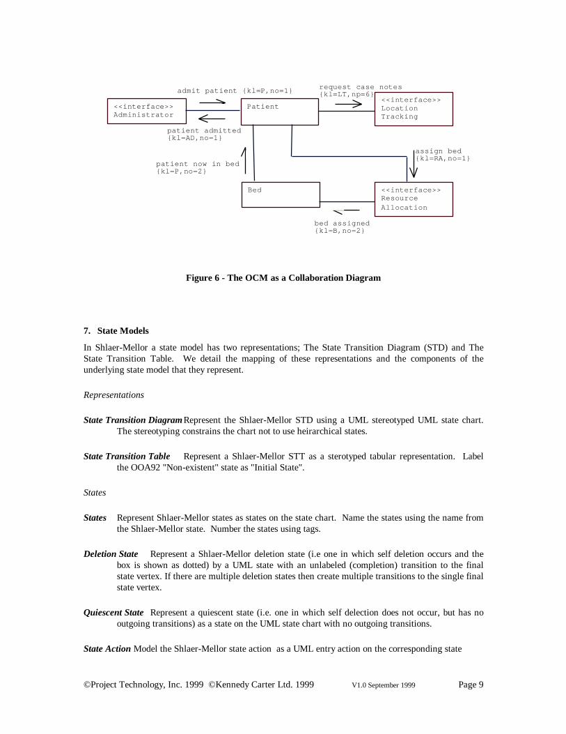
6. Object Communication Model
Represent the Shlaer-Mellor Object Communication Model (OCM) using a UML specification levelcollaboration diagram.
Objects Represent the Shlaer-Mellor object's state model (OOA91) or the object (OOA97) by a role on thecollaboration diagram. Name the role with the name of the object. Draw a line between thoseobjects that communicate with each other.
Event Transmissions Represent asynchronous communications (event transmissions in OOA92 and

©Project Technology, Inc. 1999 ©Kennedy Carter Ltd. 1999 V1.0 September 1999 Page 8
OOA97) by arrows with a half arrow head in the style of UML asynchronous message. Label themessage with the event meaning (name) from Shlaer-Mellor. Indicate the key letter and eventnumber with tags.
Syncronous Invocations Represent synchronous service invocations (from OOA97) by a arrow withfull arrow head in the style of a UML synchronous message. Label the message with the servicename from Shlaer-Mellor. Indicate the key letter and service number with tags.
Terminators Represent terminators as interfaces classes with a role on the collaboration diagram.Name the role with the name of the terminator. Stereotype type the role as <<interface>>.
Domain Based Services To represent invocations/transmissions from OOA97 domain based services,place a role on the collaboration diagram to represent the class corresponding to the domainitself. Name the role with the Key Letter of the domain.
Options The key letter and event/service number tags may be omitted if required.
Example
The following Shlaer-Mellor diagram:
Administrator
Patient
AD1:patientadmitted
P1:admit patient
Resource
Alloc
RA1:assign bed
B2:bed assigned
P2:patientnow in bed
Bed
Loc
Track
LT6:request casenotes
Figure 5 - An example Shlaer-Mellor OCM
(where dotted lines represent asynchronous communication and solid lines represent sychronousinvocations), becomes:
©Project Technology, Inc. 1999 ©Kennedy Carter Ltd. 1999 V1.0 September 1999 Page 9
admit patient {kl=P,no=1}
<<interface>>Administrator
Patient
Bed <<interface>>ResourceAllocation
<<interface>>LocationTracking
patient admitted{kl=AD,no=1}
patient now in bed{kl=P,no=2}
request case notes{kl=LT,np=6}
bed assigned{kl=B,no=2}
assign bed{kl=RA,no=1}
Figure 6 - The OCM as a Collaboration Diagram
7. State Models
In Shlaer-Mellor a state model has two representations; The State Transition Diagram (STD) and TheState Transition Table. We detail the mapping of these representations and the components of theunderlying state model that they represent.
Representations
State Transition DiagramRepresent the Shlaer-Mellor STD using a UML stereotyped UML state chart.The stereotyping constrains the chart not to use heirarchical states.
State Transition Table Represent a Shlaer-Mellor STT as a sterotyped tabular representation. Labelthe OOA92 "Non-existent" state as "Initial State".
States
States Represent Shlaer-Mellor states as states on the state chart. Name the states using the name fromthe Shlaer-Mellor state. Number the states using tags.
Deletion State Represent a Shlaer-Mellor deletion state (i.e one in which self deletion occurs and thebox is shown as dotted) by a UML state with an unlabeled (completion) transition to the finalstate vertex. If there are multiple deletion states then create multiple transitions to the single finalstate vertex.
Quiescent State Represent a quiescent state (i.e. one in which self delection does not occur, but has nooutgoing transitions) as a state on the UML state chart with no outgoing transitions.
State Action Model the Shlaer-Mellor state action as a UML entry action on the corresponding state
©Project Technology, Inc. 1999 ©Kennedy Carter Ltd. 1999 V1.0 September 1999 Page 10
Events
Event Represent Shlaer-Mellor events as signal events on the state chart. Label the signal event withthe event meaning (name) from Shlaer-Mellor. Indicate the key letter and event number withtags.
Self Directed Event Represent a Shlaer-Mellor self directed event as a UML "completion transition".This guarantees the correct semantics for the transition. However, to avoid confusion for thoseused to Shlaer-Mellor models, label the transition with the appropriate event.
Event Parameter Represent Shlaer-Mellor supplementary event data (event parameters) as signalevent parameters.
Polymorphic Event Represent OOA92 style polymorphic events as signal events with a key letterappropriate to the superclass to which they are directed. Such events should be placed used tolabel transitions as appropriate on subclass state charts. To allow for key letters not being shownon the OCM or the state chart, event names must be unique across the entire heirarchy.
Represent OOA96 style polymorphic events by creating a Polymorphic Event Table providing amapping from the superclass signal events to the appropriate subclass events. In this case evennames need only be unique within a particular class.
Effects
Transition Represent a Shlaer-Mellor state transition as a transition on the UML state chart. Label thetransition with the signal event corresponding to the appropriate Shlaer-Mellor event
Creation Transition Show a Shlaer-Mellor creation transition on the UML state chart as a transitionfrom the intial state vertex to the creation state. If there was more than one creationstate/transition, then this should be shown as multiple transitions from the single initial statevertex.
Ignore Represent the Shlaer-Mellor "ignore" response on the UML state chart by showing an internaltransition on the appropriate state labeled with the signal event which is ignored. Show noaction for the transition.
Cannot Happen Represent the Shlaer-Mellor "cannot happen" response on the UML state chart byshowing an internal transition on the appropriate state labeled with the signal event which"cannot happen". Show a stereotyped action <<cannot happen5>> for the internal transition.
Shouldn't Happen Represent the OOA97 "shouldn't happen" response on the UML state chart byshowing an internal transition on the appropriate state labeled with the signal event which"shouldn'thappen". Show a stereotyped action <<shouldn't happen6>> for the internal transition.
5 <<cannot happen>> is a UML "raise" action that causes raising of an exception.
6 <<shouldn't happen>> is a UML "raise" action that causes raising of an exception.
©Project Technology, Inc. 1999 ©Kennedy Carter Ltd. 1999 V1.0 September 1999 Page 11
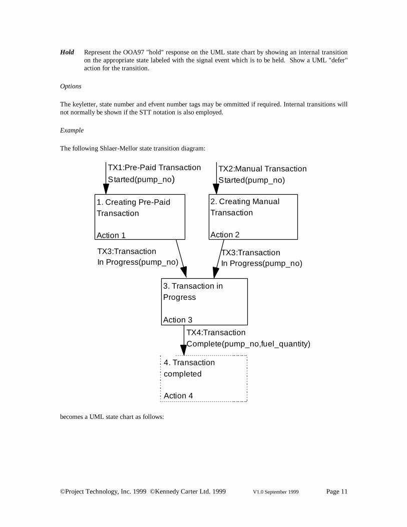
Hold Represent the OOA97 "hold" response on the UML state chart by showing an internal transitionon the appropriate state labeled with the signal event which is to be held. Show a UML "defer"action for the transition.
Options
The keyletter, state number and efvent number tags may be ommitted if required. Internal transitions willnot normally be shown if the STT notation is also employed.
Example
The following Shlaer-Mellor state transition diagram:
1. Creating Pre-PaidTransaction
Action 1
2. Creating ManualTransaction
Action 2
3. Transaction inProgress
Action 3
4. Transactioncompleted
Action 4
TX1:Pre-Paid TransactionStarted(pump_no)
TX2:Manual TransactionStarted(pump_no)
TX3:TransactionIn Progress(pump_no)
TX3:TransactionIn Progress(pump_no)
TX4:TransactionComplete(pump_no,fuel_quantity)
becomes a UML state chart as follows:

©Project Technology, Inc. 1999 ©Kennedy Carter Ltd. 1999 V1.0 September 1999 Page 12
Creating Pre-Paid Transaction{no=1}entry/Action 1
Creating Manual Transaction{no=2}entry/Action 2
Transaction in Progress {no=3}entry/Action 3
Transactioncompleted {no=4}entry/Action 4
Pre-Paid TransactionStarted(pump_no) {kl=TX,no=1}
Manual TransactionStarted(pump_no) {kl=TX,no=2}
TransactionIn Progress(pump_no){kl=TX,no=3}
TransactionIn Progress(pump_no){kl=TX,no=3}
TransactionComplete(pump_no,fuel_quantity){kl=TX,no=4}
8. Assigner State Models
Represent an OOA91 assigner state model by a state chart sterotyped as <<assigner>> attached to theassociative class. The streotyping prehibits creation states, deletion states and polymorphism. Labelevents with a key letter in the form "<class kl>-A".
Represent an OOA96 assigner state model by a state chart sterotyped as <<assigner>> attached to thepartititioning association. The streotyping prehibits creation states, deletion states and polymorphism.Label events with a key letter in the form "R<association number>-A".

©Project Technology, Inc. 1999 ©Kennedy Carter Ltd. 1999 V1.0 September 1999 Page 13
9. Synchronous Operations
Represent OOA92 and OOA97 style synchronous services as UML operations with the correspondingservice actions as UML methods7. The invocation of such operations is shown on the OCM as describedpreviously. Optionally, the services can also be shown in the Class Diagram.
10. Acknowledgements
Both authors are indebted to the many people who have contributed ideas over the years.
In particular, SJM would like to thank....
ITW would like to thank all the consultants and developers at Kennedy Carter. In particular for thespecific issue of the UML mapping, he has benefited from many useful conversations with Colin Carterand Paul Francis. Andy Land deserves special praise for the painstaking care with which he picked hisway through the 300+ pages on the UML specification in order to ensure the correctness of the mappings.
7 Note that UML 1.3 does not allow methods to have “actions”. This is certain to be changed in the“Precise Action Semantics” enhancement to UML currently being defined under the auspices of the OMG.

©Project Technology, Inc. 1999 ©Kennedy Carter Ltd. 1999 V1.0 September 1999 Page 14
11. Method Baselines
Since the publication of the first book on OOA by Shlaer and Mellor various clarifications and extensionshave been issued. In addition, others have contributed ideas, many of which are in active use. Theintention of this section is to summarise these so that the discussion of the mapping to UML may be seenin context. It is not intended that this in any way replaces the published definitions of these extensions andin case of doubt the original publications should be consulted.
A complication in defining clear versions of the method is that there have often been a continuous seriesof minor improvements that have been incorporated into, for example, training material or consultingwork on real projects without there having been an "official" and published release. Nevertheless, it isuseful and convenient to attempt to define such versions.
11.1 OOA 88
This method, described in [M1] is confined mainly to Information Modelling with a minimal treatment ofdynamic modelling and “design by translation”.
11.2 OOA 91
The method as published in “Object Lifecycles: Modelling the World in States” [M2], represents the firstvirtually complete description of OOA as we might recognise today. It differs from OOA 88 in thefollowing respects:
• Minor Improvements to the Information Modelling formalism and notation such as NumberedRelationships.
• Substantial definition of dynamic behaviour in terms of interacting state machines executingmodels represented by State Transition Diagrams and State Transition Tables. Included with thiswas a treatment of the rules of synchronisation and concurrency within an OOA model.
• Introduction of the idea of domain partitioning with an outline treatment of bridges.
• A discussion of the Software Architecture that emphasised the idea of translation as systemconstruction approach.
11.3 OOA 92
While developing CASE tool support that understood the formalism Kennedy Carter extended thedefinition and notation some areas. Most of these issues were documented in the product’s User Guide,although some technical notes were written.
The following issues were addressed:
Information Models
The following changes were made:
©Project Technology, Inc. 1999 ©Kennedy Carter Ltd. 1999 V1.0 September 1999 Page 15
• The case of a general n-way relationship that had briefly been mentioned in OOA 88 but omittedfrom OOA 91 was withdrawn completely from our support. Our experience was that suchrelationships are very hard to understand and the real-world issues that they represent are betterdescribed by a number of simpler relationships.
• The notion of an "attribute domain", which was informally described in OOA 91 was tightened toinclude the idea of a data type with optional constraint.
State Models
In order to make the STT representation a complete description of the state model the following wereadded:
• A row representing the state of an instance before its creation. This pseudo-state enables the STTto show creation transitions. In addition, it allows the analyst to distinguish between the arrivalof an event targeted at a non-existent instance being an error ("Cannot Happen") and beingexpected ("Ignore").
• The addition of the effect "Meaningless" for events arriving for instances in a state where theinstance is deleted.
Other changes were:
• The notion of a polymorphic event was formally introduced [M12,M13].
• The idea of “synchronous services” was introduced [M7]. Such services specify processing thatis executed synchronously with respect to the invocation and can return data to the invoking stateaction. OOA 97 refined the ideas and introduces the formal association of such services withobjects and with object instances.
• Self directed events go to the head of the event queue for an instance. (Previously this was arecommendation only).
Process Models
• The Action Specification Language (ASL) [M10] was introduced as an alternative to Action DataFlow Diagrams (ADFDs) for specifying process models.
Domains and Bridges
• Introduction of an “OOA of Bridges” describing all the possible bridges mappings that can existbetween OOA domains [M8].
• Interaction with other domains captured through events being sent to8/from terminators.Guidelines were provided for the level of abstraction for the terminator (i.e. that the terminator
8 In OOA 97 the idea of an event being sent to a terminator was replaced with a “terminator serviceinvocation” akin to a wormhole [M6].

©Project Technology, Inc. 1999 ©Kennedy Carter Ltd. 1999 V1.0 September 1999 Page 16
represents the “ultimate source or sink” of a structured analysis “essential model” rather than thedomain that implements it).
11.4 OOA 96
The “OOA 96 Report” [M3] tidied up a number of a number of loose ends in the description of OOA 91and introduced some additional concepts. Some of these concepts had previously been described inProject Technology training material, but not incorporated in an “official” description of the method.
In outline the areas addressed were:
Information Models
• Clarification of the ideas of mathematical and stochastic dependence of attributes. Introduction ofthe notation (M) for mathematically dependent attributes replacing the (D) notation usedpreviously.
• Clarification of the idea of relationship loops and composed relationships.
• Clarification to the ideas of reflexive relationships and the introduction of a new special case ofsymmetric reflexive relationships.
State Models
• Notational distinction between identifying event parameters and supplemental data.
• Events can no longer be sent to terminators.
• Self directed events go to head of the event queue for an instance.
• Formal introduction of polymorphic events through the idea of a “Polymorphic Event Table”
• Clarification to the definition of the operation of the Finite State Machine mechanism.
• Occurrence of “Cannot Happen” at run time defined as an analyst error.
• Introduction of the new concept of “multiple assigners”
• Clarifications to the rules surrounding object instance creation and deletion
Process Models
• Process models are not longer allowed to access the “Current State” attribute of an active object(except in the special case of synchronous creation).

©Project Technology, Inc. 1999 ©Kennedy Carter Ltd. 1999 V1.0 September 1999 Page 17
• Introduction of the “proper attribution” rule for transient data on ADFDs9
• Introduction into ADFDs of the ideas of “base processes” working on (possibly ordered) sets ofdata, thus formally supporting the idea of iteration.
• Changes to the allowable properties of different process types on ADFDs.
• Replacement of the “Timer” mechanism with a simpler “Delayed Event” mechanism.
• Introduction of the term “wormhole” to refer to the invocation of services provided by otherdomains.
11.5 OOA 97
OOA 97 was an accumulation of a number of issues that built up in the course of consultancy work.These issues were then gathered into a single OOA 97 document [M9].
• Refinement of the idea of synchronous services by formal association of services with domains,objects and instances of objects. In ASL this association was captured with a defined syntax forthe service calls.
• Introduction of the additional FSM responses of “Hold” and “Shouldn’t Happen”. The first ofthese was to deal with a specific class of problem complexity, the second in response to the OOA96 rules that classify “Cannot Happen” as an analysis error if it does happen.
• Introduction of exception handling mechanisms within the OOA formalism.
• Introduction of support from the formalism for both “Deferred” and “Dynamic” data types.
• Introduction of a comprehensive support for the definition of Bridges within OOA/ASL includingthe idea of “counterpart relationships”.
In order to support these ideas, the definition of ASL was upgraded from ASL 2.4 to ASL 2.5.
11.6 OOA 96++
Since the OOA 96 report, Shlaer and Mellor issued further method documents [M5, M6, M7] on thesubjects of Data Types, Bridges & Wormholes and Synchronous Services. For convenience we refer tothese as OOA 96++.
• Introduction of formal notion of a Data Type with a base type, range and precision and units
9 This rule has been subsequently refined to the idea that all transient flows should have a defined type[M4].
©Project Technology, Inc. 1999 ©Kennedy Carter Ltd. 1999 V1.0 September 1999 Page 18
• Introduction of idea of wormholes with client-server associations managed through transfervectors
• Introduction of idea of a synchronous service provided by a domain.

©Project Technology, Inc. 1999 ©Kennedy Carter Ltd. 1999 V1.0 September 1999 Page 19
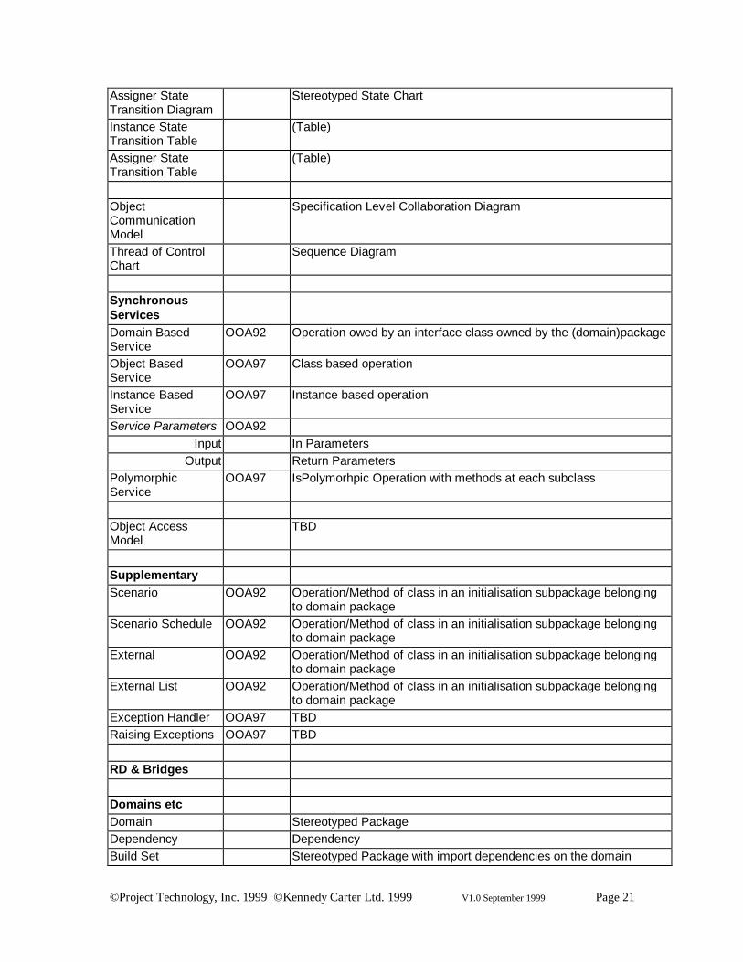
12. Shlaer-Mellor to UML Meta-Model Mapping
The following table outlines the mappings between Shlaer-Mellor modelling concepts and the UML meta-model. These mappings have been chosen to be strictly correct in terms of the definition of the semanticsbehind the meta-model.
Shlaer-MellorConcept
VersionSpecific
UML Concept
InformationModellingObject Constrained ClassAttribute AttributeIdentifier Collaboration of AttributesBinary Relationship AssociationSuper/Sub TypeRelationship
Constrained Generalisation
AssociativeRelationship
Association Class
SymmetricReflexiveRelationship
Stereotyped Association
ComposedRelationship
Association with Constraint
Referential Attribute Attribute with TagMathematicalDependancy
Attribute with Constraint and Tag
Attribute Constraint ConstraintBase Types
Integer OOA92 TypeReal/Numeric Type
Boolean TypeExtended Boolean OOA96++ Type
Ordinal OOA96++ TypeDuration OOA96++ Type
Time-of-Day TypeDate Type
Text/Symbolic TypeArbitary OOA96++ Type
Untyped InstanceHandle
OOA92 Type
Domain SpecificTypes
Constrained BaseType
Type

©Project Technology, Inc. 1999 ©Kennedy Carter Ltd. 1999 V1.0 September 1999 Page 20
Enumeration TypeStructure Set OOA92 Type
Typed InstanceHandle
OOA92 Type
Dynamic OOA97 TypeDeferred OOA97 Type
Units OOA96++ TypeDefault Value OOA96++ Type
Range TypePrecision Type
Object Instance ObjectRelationshipInstance
Link
Information ModelDiagram
Stereotyped Class Diagram
State ModellingInstance StateModel
Constrained State Machine asscociated with Class
Assigner StateModel
OOA91 Constrained State Machine asscociated with ClassOOA96 Constrained State Machine asscociated with Class and Association
State StateEvent Constrained Signal/Reception Pair. "Event Direction" maps to
Reception is BehaviouralFeature is Feature is owned by classifier isclass(model element), Tied to event on state machine by associationwith Signal Event
EffectsTransition Transition
Cannot Happen Transition associated with State by Internal Transition with TagIgnore Transition associated with State by Internal Transition with Tag
Hold OOA97 Event associated by "deferred event" to stateShouldn't Happen OOA97 Transition associated with State by Internal Transition with Tag
Non-existent State OOA92 Initial Pseudo-StateCreationEvent/State/Transition
Constrained Signal Event/State/Transition from Pseudo-State to thestate
Terminal State Constrained State that calls destroy event at end of entry actionTerminator Sterotyped Class, visible outside the packageEvent Parameter Parameter on Signal EventPolymorphic Events
OOA92 Each "event availability" is an additional signal reception ultimatelyowned by the class for which is is available
OOA96 Each "OOA event" alias is an additonal signal & reception "raised" bythe aliased signal/reception pair
Instance StateTransition Diagram
Stereotyped State Chart
©Project Technology, Inc. 1999 ©Kennedy Carter Ltd. 1999 V1.0 September 1999 Page 21
Assigner StateTransition Diagram
Stereotyped State Chart
Instance StateTransition Table
(Table)
Assigner StateTransition Table
(Table)
ObjectCommunicationModel
Specification Level Collaboration Diagram
Thread of ControlChart
Sequence Diagram
SynchronousServicesDomain BasedService
OOA92 Operation owed by an interface class owned by the (domain)package
Object BasedService
OOA97 Class based operation
Instance BasedService
OOA97 Instance based operation
Service Parameters OOA92Input In Parameters
Output Return ParametersPolymorphicService
OOA97 IsPolymorhpic Operation with methods at each subclass
Object AccessModel
TBD
SupplementaryScenario OOA92 Operation/Method of class in an initialisation subpackage belonging
to domain packageScenario Schedule OOA92 Operation/Method of class in an initialisation subpackage belonging
to domain packageExternal OOA92 Operation/Method of class in an initialisation subpackage belonging
to domain packageExternal List OOA92 Operation/Method of class in an initialisation subpackage belonging
to domain packageException Handler OOA97 TBDRaising Exceptions OOA97 TBD
RD & Bridges
Domains etcDomain Stereotyped PackageDependency DependencyBuild Set Stereotyped Package with import dependencies on the domain

©Project Technology, Inc. 1999 ©Kennedy Carter Ltd. 1999 V1.0 September 1999 Page 22
packages that it usesDomain Chart Package Diagram
ContractsContract N/AContract Type N/AClosure Service Signal or Operation
BridgesTerminator Service OOA92 Operation on Stereotyped ClassUntyped IH/TransferVector
OOA96++/OOA97
Parameters on the operation
ASLMapping/BridgeTable
OOA97 Method provided by class in the build set package
Peer-to-PeerCounterpartRelationship
OOA97 association between terminator classes in imported domain packages
Specific/GenericRelationship
OOA97 generalisation between SCT and specific classes in imported domainpackages
Explicit S/G CPMapping
OOA97 Stereotyped method provided by the SCT class which raises thespecific class operation
Implicit S/G CPMappingsEvent Consumption OOA97 Action on transition
Pre-State OOA97 Addition to entry actionPost-State OOA97 Addition to end of entry action
Pre-Service OOA97 Additional method with pre-appendagePost-Service OOA97 Additional method with post-appendage
Attribute Access OOA97 TBD
ArchitecturesTag Group TagTag(Colour) TagTag Attachment(Colourisation)
Application of Tag (Tag Value)
MiscellaneousSubsystems
Subsystem PackageForeign Object Imported Class
ForeignRelationship
Association belonging to imported class
SubsystemRelationship Model
Stereotyped Package Diagram
SubsystemCommunication
Stereotyped Package Diagram

©Project Technology, Inc. 1999 ©Kennedy Carter Ltd. 1999 V1.0 September 1999 Page 23
Subsystem AccessModel
Stereotyped Package Diagram

©Project Technology, Inc. 1999 ©Kennedy Carter Ltd. 1999 V1.0 September 1999 Page 24
References
[M1] Sally Shlaer and Stephen J. MellorObject Oriented Analysis: Modeling the World in DataPrentice Hall, 1988
[M2] Sally Shlaer and Stephen J. MellorObject Oriented Analysis: Modelling the World in StatesPrentice Hall, 1992
[M3] Sally Shlaer and Neil LangThe OOA96 ReportProject Technology, 1995
[M4] Sally Shlaer and Stephen J. MellorData Types in OOAProject Technology, 1997
[M5] Sally Shlaer and Stephen J. MellorBridge and WormholesProject Technology, 1996
[M6] Sally Shlaer and Stephen J. MellorBridge and WormholesProject Technology, 1996
[M7] Sally Shlaer and Stephen J. MellorSynchronous ServicesProject Technology, 1996
[M8] Christopher RaistrickA Practitioners Guide to the Use of Bridges in Shlaer-Mellor Recursive DevelopmentKennedy Carter, 1994
[M9] Ian Wilkie, Colin Carter and Paul FrancisOOA 97Kennedy Carter (KC/OOA/CTN 53)
[M10] Ian Wilkie, Adrian King, Mike Clarke and Chas WeaverThe Action Specification Language (ASL) Reference ManualKennedy Carter, (KC/OOA/CTN 06)
[M11] Ian WilkieSynchronous ServicesKennedy Carter, 1994 (KC/OOA/TN 44)
[M12] Ian WilkiePolymorphic EventsKennedy Carter, 1994 (KC/OOA/CTN 09)
[M13] Paul Francis and Ian WilkiePolymorphic Events in OOA/RD
©Project Technology, Inc. 1999 ©Kennedy Carter Ltd. 1999 V1.0 September 1999 Page 25
Kennedy Carter, 1999 (KC/OOA/CTN 57)
[M14] Stephen J. Mellor and Neil LangDeveloping Shlaer-Mellor Models in UMLProject Technology, 1997
[M15] Christopher Raistrick, Dean Spencer and Ian WilkieOOA/RD to UML MappingKennedy Carter, 1998 (KC/OOA/CTN 64)