a m u (amu) - rmspl.com.au · 1686-2007 and ieee std c37.231-2006 can be installed in the control...
TRANSCRIPT
MGU010000-SP-en
Analog Merging Unit (AMU) Datasheet 2015-09-18
© VIZIMAX, 2015. All rights reserved. 1
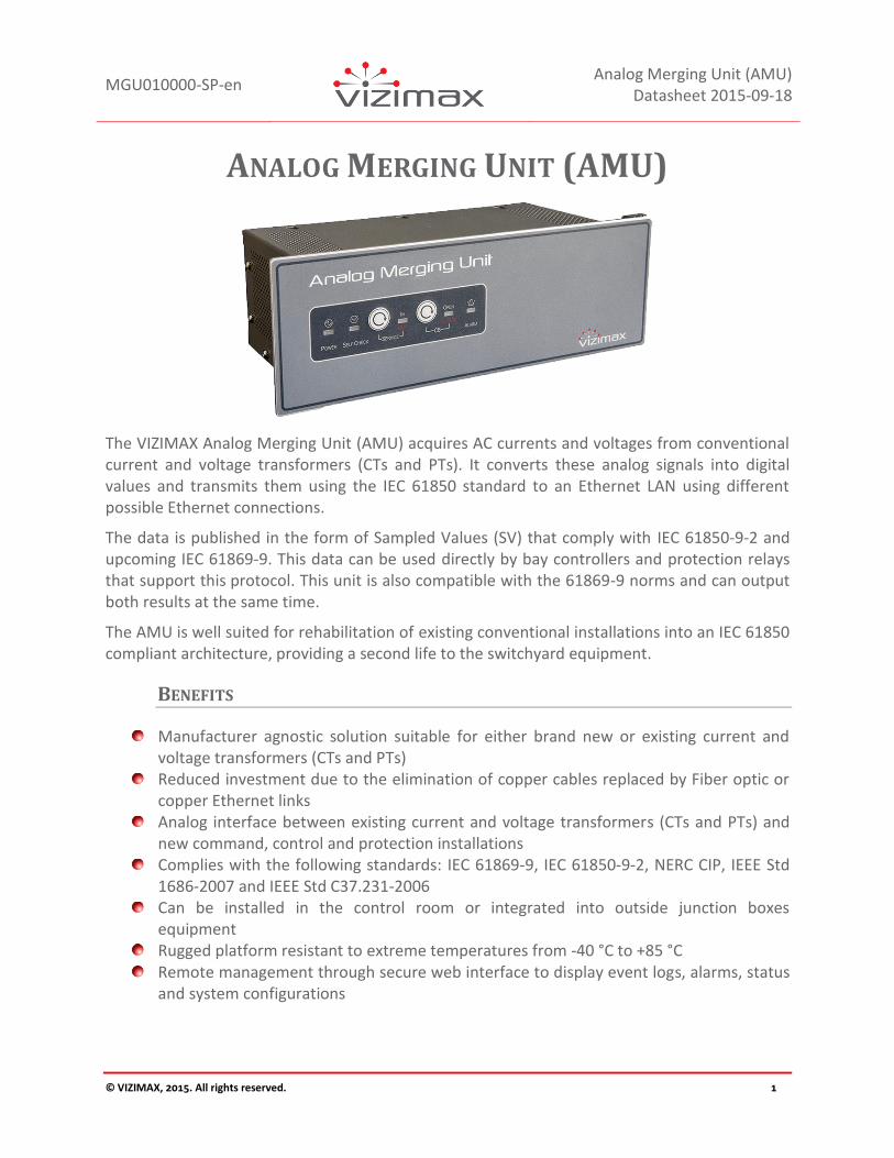
ANALOG MERGING UNIT (AMU)
The VIZIMAX Analog Merging Unit (AMU) acquires AC currents and voltages from conventional current and voltage transformers (CTs and PTs). It converts these analog signals into digital values and transmits them using the IEC 61850 standard to an Ethernet LAN using different possible Ethernet connections.
The data is published in the form of Sampled Values (SV) that comply with IEC 61850-9-2 and upcoming IEC 61869-9. This data can be used directly by bay controllers and protection relays that support this protocol. This unit is also compatible with the 61869-9 norms and can output both results at the same time.
The AMU is well suited for rehabilitation of existing conventional installations into an IEC 61850 compliant architecture, providing a second life to the switchyard equipment.
BENEFITS
Manufacturer agnostic solution suitable for either brand new or existing current and voltage transformers (CTs and PTs)
Reduced investment due to the elimination of copper cables replaced by Fiber optic or copper Ethernet links
Analog interface between existing current and voltage transformers (CTs and PTs) and new command, control and protection installations
Complies with the following standards: IEC 61869-9, IEC 61850-9-2, NERC CIP, IEEE Std 1686-2007 and IEEE Std C37.231-2006
Can be installed in the control room or integrated into outside junction boxes equipment
Rugged platform resistant to extreme temperatures from -40 °C to +85 °C Remote management through secure web interface to display event logs, alarms, status
and system configurations

MGU010000-SP-en
Analog Merging Unit (AMU) Datasheet 2015-09-18
© VIZIMAX, 2015. All rights reserved. 2
FEATURES
TIME SYNCHRONIZATION
The AMU time synchronization is provided through an IEC 61588 PTP compliant master clock, optional internal GPS or with the use of a PPS synchronization signal received through an electric pulse or a fiber optic connection. Either of these approaches allow for the accuracy required when publishing the sampled value data information via the IEC 61869-9 and IEC 61850-9-2 protocol.
V I
3 Ø power system
Conventional
voltage/current
transformers
Ethernet
100BaseFX
Interface
IEC 61588 PTP/
Fiber Optic PPS
master clock
IEC 61588 PTP
Time protocol
Fiber optic
PPS sync.
IEC 61850-9-2
data consumer
IED
IEC 61850-9-2LE
Sampled values
(4 x V, 4 x I)
Ethernet
100BaseFX
Interface
DATA TRANSMITTED BY THE AMU
The AMU publishes sampled values according to the multicast sampled values control block 01 (MSVCB01 or MSVCB02) as defined in the 9-2LE guide. Targeting protection relays and bay controllers, sampling occurs 80 times per cycle (thus 4000 or 4800 times per second depending on nominal network frequency, i.e. 50 Hz or 60 Hz). When the measurement sampling is selected, the unit samples at a rate of 256 samples per cycle (12800 sample/s to 15360 sample/s) and transmits this information in blocks of 8 per the standard to minimize bandwidth usage. Two more publishing configuration available for the upcoming IEC 61869-9. The unit provides the capability of sampling and transmitting data according to the protection portion of the standard or based on the measurement portion of the standard.
COMMUNICATION LINKS
The unit can be configured to use either or both Ethernet port 1 and port 2 for the SV’s data transmission also leaving room for the reception of control signals if so required by the user’s application (i.e. GOOSE messaging). A third Ethernet port is located on the AMU front panel providing a local service port and can be used for remote maintenance. The AMU offers the option to support the parallel redundancy protocol (PRP). The unit can be ordered either with 100BASE-T, 100BASE-FX or 100BASE-LX with RJ45, ST or LC connectors.

MGU010000-SP-en
Analog Merging Unit (AMU) Datasheet 2015-09-18
© VIZIMAX, 2015. All rights reserved. 3
MOUNTING
The Analog Merging unit has the following characteristics:
DIMENSIONS
Specifications Value
Width
257 mm (0.125 in) for standard mount
305 mm (12 in) for panel mount
483 mm (19 in) for Rack mount
Height
92 mm (3.6 in) for standard mount
105 mm (4.1 in) for panel mount
U3 132.56 mm (5.219 in) for Rack mount installation
Depth 134 mm (5.25 in)
Weight
Standard mount 3.0 kg (6.6 lbs)
Panel mount 3.3 kg (7.3 lbs)
Rack mount 3.6 kg (8 lbs)
STANDARD MOUNT
The AMU standard mount is a breeze to install. It can be mounted directly inside a breaker control enclosure. It also includes movable mounting brackets for multiple mounting positions (horizontal or vertical).
FIGURE 1 STANDARD MOUNT

MGU010000-SP-en
Analog Merging Unit (AMU) Datasheet 2015-09-18
© VIZIMAX, 2015. All rights reserved. 4
PANEL MOUNT
The AMU panel mounts within a rectangular cut-out on any control enclosure. It includes dual control panels. Panel footprint: 105 mm x 305 mm (4.1 in x 12.0 in), pinch brackets provided.
FIGURE 2 PANEL MOUNT (FACTORY OPTION)
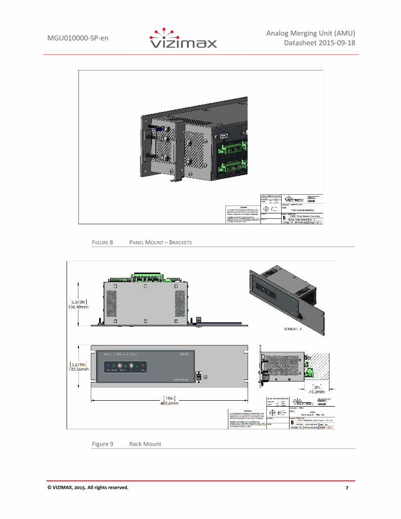
RACK MOUNT
The AMU rackmount mounts to standard 19 in rack and includes dual control panels. The Ethernet port service is accessible from the front. Panel size: 3U standard panel (5.219 in x 19 in).
A DIN rail - 120 mm (4.8 in) - is provided on the rear panel to mount terminal blocks or IED accessories (Protocol converters, copper to optical fiber interface, etc.)
FIGURE 3 19 IN. RACK MOUNT (FACTORY OPTION)

MGU010000-SP-en
Analog Merging Unit (AMU) Datasheet 2015-09-18
© VIZIMAX, 2015. All rights reserved. 5
FIGURE 4 STANDARD MOUNT – HORIZONTAL
FIGURE 5 STANDARD MOUNT – VERTICAL

MGU010000-SP-en
Analog Merging Unit (AMU) Datasheet 2015-09-18
© VIZIMAX, 2015. All rights reserved. 6
FIGURE 6 PANEL MOUNT
FIGURE 7 PANEL MOUNT – CUT-OUT
MGU010000-SP-en
Analog Merging Unit (AMU) Datasheet 2015-09-18
© VIZIMAX, 2015. All rights reserved. 7
FIGURE 8 PANEL MOUNT – BRACKETS
Figure 9 Rack Mount

MGU010000-SP-en
Analog Merging Unit (AMU) Datasheet 2015-09-18
© VIZIMAX, 2015. All rights reserved. 8
AMU TECHNICAL CHARACTERISTICS
COMPLIANCE
SPECIFICATIONS
Specifications Standard Reference No. Value
Temperature range
Operating temperature IEC-68-2-1
IEC-68-2-2 -40 °C to +85 °C (* see note)
Storage temperature -50 °C to +85 °C
Relative humidity (R.H.) < 95% without condensation
Maximum altitude < 2000 m
Pollution degree Level 2
IP rating IP30
Mechanical resistance to vibrations
Performance IEC 60255-21-1, 21-2, 21-3 Class 2
Endurance IEC 60255-21-1, 21-2, 21-3 Class 1
Dielectric withstand
AC inputs and I/Os IEC 60255-5 2200 V ac, 1 s
Communication IEC 60255-5 1650 V ac, 1 s
Impulse voltage withstand IEC 60255-5 5 kV
Electrostatic discharge (ESD)
Air discharge IEC 61000-4-2 15 kV
Direct contact discharge
IEC 61000-4-2 8 kV
Damped oscillatory wave (1 MHz burst)
Common mode IEC 60255-22-1 2.5 kV
Differential mode 1.0 kV
Fast transients (bursts) IEC 60255-22-4 Level 4
RF immunity
IEC 61000-4-3 20 V/m, from 80 MHz to 1 GHz
IEC 60255-26 Spot frequency: 80 MHz to 2150 MHz
ANSI/IEEE 1613 10 V/m, from 1.4 GHz to 2.7 GHz

MGU010000-SP-en
Analog Merging Unit (AMU) Datasheet 2015-09-18
© VIZIMAX, 2015. All rights reserved. 9
SN62. 1008-1 3 V/m, from 5.15 GHz to 5.75 GHz
Conducted disturbance immunity IEC 61000-4-6 150 kHz to 80 MHz
RF emissions CISPR 11, CISPR 22, FCC Class A
Safety IEC 61010-1, 3
rd edition
ISO 14971: 2012
Equipment for measurement, control, and laboratory use
*See Temperature Test Performances below.
TEMPERATURE TEST PERFORMANCES
Specifications Standard Reference No. Value
Operating Temperature
Operating Temperature excludingUL applications
IEC 68-2-2 -40 °C to +85 °C
Derated Operating temperature for UL applications
IEC 610110-1 -40 °C to +75 °C
Temperature Type testing
Cold IEC 68-2-1 -40 °C (16 hours, -50 °C cold start)
Dry heat IEC 68-2-2 75 °C (16 hours)
Damp heat cyclic IEC 68-2-30 55 °C at 95% R.H. (144 hours)
LOCAL USER INTERFACE
Specifications Value
Two push buttons User configurable: information In/Out of service: information
Six LEDs Service, alarm, communication activity, system status and power
Front panel USB port
Interface compatibility 2.0
Maximum speed 480 Mbit/s
Connector type Type B
Voltage isolation level N/A

MGU010000-SP-en
Analog Merging Unit (AMU) Datasheet 2015-09-18
© VIZIMAX, 2015. All rights reserved. 10
COMMUNICATION PORTS
Port Characteristics Value
Ethernet – LAN-1
Interface 10/100 Mbps
Connector RJ-45, ST or LC (for fiber connection)
Isolation 1500 VRMS
Connector name Port 1
Function AMU connection links
Ethernet – LAN-2
Interface 10/100 Mbps
Connector RJ-45, ST or LC (for fiber connection)
Isolation 1500 VRMS
Connector name Port 2
Function AMU connection links
Ethernet – Service (front)
Interface 10/100 Mbps
Connector RJ-45
Isolation 1500 VRMS
Connector name Port service–initial unit configuration and setup
Function Service port
RS-232 serial Connector DB-9
Bit rate 115 Kbps
Function Console port, service operations
RS232 or RS-485 isolated serial
Connector Phoenix type, 3.81 mm secured by screws
Bit rate 38.4 Kbps
Mode
Two wire interface (A-B) with jumper selectable 120 Ω terminations. Reference wire (0V) provided for high-common-mode voltage capability
Isolation 2000 VRMS
Function Future use

MGU010000-SP-en
Analog Merging Unit (AMU) Datasheet 2015-09-18
© VIZIMAX, 2015. All rights reserved. 11
DATA COMMUNICATION OPTIONS
COMMUNICATION SETTINGS
Specifications Value
2x Ethernet connections Copper PRP or Fiber Optic PRP
2x clients IP transport UDP, TCP, TCP/UDP or UDP spontaneous
DIGITAL INPUTS
The AMU has 10 digital inputs split into 2 groups, one of 6 inputs with one common and a group of 4 with their own common.
Specifications Value
Name IN 1 to 10
Number of inputs 10
Rating V (option 48) 72 V dc, (detection threshold 28 V dc)
Rating V (option 125) 140 V dc, (detection threshold 80 V dc)
Rating V (option 220) 280 V dc, (detection threshold 150 V dc)
Isolation Opto-coupler, 2000 VRMS
Measuring Category MEAS CAT IV
Burden 2 mA to 5 mA
Hardware response Time <0.10 ms at nominal voltage and <1.00 ms at 80% of nominal voltage
Software Filter Programmable, 1 ms increments up to 250ms. Advanced chatter filter
Connector Phoenix MSTB 5.08mm, pluggable screw type.

MGU010000-SP-en
Analog Merging Unit (AMU) Datasheet 2015-09-18
© VIZIMAX, 2015. All rights reserved. 12
SIGNALING OUTPUTS
The AMU has 4 signaling outputs available and one output is reserved for future use.
Specifications Value
Quantity 2x form A and 2x form C dry contact outputs (1 form C reserved for system health status)
Status System, Timesync, in/out of service
Type Electromechanical relays
Rating V, A (AC) 250 V ac, 3 A maximum
Rating V, A (DC) 250 V dc, 0.3 A maximum
Contact ratings 250 V ac, 300 V dc
Contact breaking capacity 10 A at 250 V ac 8 A @ 30 V, 0.5 A @ 125 V, 0.3 A at 250 V dc
Isolation 5000 VRMS coil to contacts
Over voltage category OVC CAT III
Connector Phoenix MSTB 5.08 mm, pluggable screw type

MGU010000-SP-en
Analog Merging Unit (AMU) Datasheet 2015-09-18
© VIZIMAX, 2015. All rights reserved. 13
CT AND PT MEASUREMENTS INPUTS
The AMU is used to measure current using current transformers (CTs), and the source (line or bus) voltage using potential transformers (PTs).
CT INPUTS
Specifications Value
Number of inputs 4
Name IA, IB, IC and IN
Connector type Phoenix PC-6, 10.16 mm, pluggable screw AWG 6-16 – 0.5 mm
2 –
6.0 mm2
Current
Rated current 1 A or 5 A, manufacturing selectable
Saturation current 160 A @ 5 A range / 40 A @ 1 A range
Maximum current
500 A @ 0.05 s
100 A @ 1.0 s
20 A continuous
Measurement category MEAS CAT IV
Burden @ rated current < 0.01 VA @ 1 A, <0.1 VA @ 5 A, <4 VA @ 40 A
Isolation 3000 VRMS
Asymmetrical current Typical: 98% continuous
Guaranteed: 95% continuous
Nominal frequency range 40 Hz to 70 Hz
Measurement bandwidth (-3 dB) DC to 3 kHz
Sampling frequency 19200/s
Conversion resolution 20 bits
Accuracy 5 A range
Typical: ±0.03% @ 25 °C (±6PPM/°C) <14 A
Guaranteed: ±0.1% @ 25 °C + (± 20PPM/ °C) <14 A
±0.5 to 0.8% @ 25 °C + (± 125PPM/ °C) >14 A
after 15 minutes warm-up
Accuracy 1 A range
Typical: ±0.03% @ 25 °C (±6PPM/°C) <3.5 A Guaranteed: ±0.1% @ 25 °C + (± 20PPM/ °C) <3.5 A ±0.5 to 0.8% @ 25 °C + (± 125PPM/ °C) >3.5 A after 15 minutes warm-up

MGU010000-SP-en
Analog Merging Unit (AMU) Datasheet 2015-09-18
© VIZIMAX, 2015. All rights reserved. 14
PT INPUTS
Specifications Value
Number of inputs 4
Name VA, VB, VC and VN
Connector type Phoenix MSTB 5.08 mm, pluggable screw type
Rated voltage 69 V ac to 200 V ac
Thermal capacity (1 minute) 220 V ac
Measurement category MEAS CAT IV
Burden <0.05 VA
Isolation 3000 VRMS
Nominal frequency range 40 Hz to 70 Hz
Measurement bandwidth (-3 dB) DC to 3 kHz
Sampling frequency 19200/s
Conversion resolution 16 bits
Accuracy Typical: ±0.05% @ 25°C + (±10 PPM/ °C)
Guaranteed: ±0.1% @ 25 °C + (±15 PPM/ C)
after 15 minutes warm-up

MGU010000-SP-en
Analog Merging Unit (AMU) Datasheet 2015-09-18
© VIZIMAX, 2015. All rights reserved. 15
POWER SUPPLY
The power supply is set according to the ordering options. Up to 4 digital outputs are provided to signal alarm conditions to external devices such as RTUs and annunciators. These can also drive external devices in the unlikely scenario the AMU becomes defective or out of service.
POWER SUPPLY
Specifications Value
Rating (48 V) 36 V dc - 72 V dc
Rating (125 V) 100 V dc - 140 V dc
Rating (220 V) 180 V dc - 280 V dc
Rated power 29 W max. (typical 18 w, 0.14 A @ 125 V dc )
Connector Phoenix MSTB 5.08 mm
Isolation 3000 V during 1 s
Fuse Time delay, 2 x 2 A (not user serviceable)
Voltage interrupt > 100 ms @ 100%
INTERNAL TIME BASE
Internal clock is synchronized either by the 1588 Ethernet clock or the fiber/electrical PPS input or by GPS input.
Specifications Value
Base precision < 100 nanosecond, after 15 minutes warm-up
Time for a drift of 1.0 μs on external time based lost
Typical: ≈1200 s Guaranteed: >400 s @ 25 °C after 15 minutes warm-up
PPS with Ethernet IEEE PTP 1588
RJ45, Fiber ST or Fiber LC Base precision < 25 nanosecond
IRIG-B 000 un-modulated or PPS in fiber optic
ST type frequency range: 820-850 nanometers Base precision < 75 nanosecond
IRIG-B 000 un-modulated or PPS in BNC
Zin: 500 Ω /50 Ω selectable by software Level: 3.3 V dc to 5 V dc Base precision < 85 nanosecond
PPS out BNC Zout: 10 Ω Vout: 5 V dc, Iout max = 100 mA
GPS option GPS option replaces PPS fiber optic input with an SMA antenna connector. Base precision < 45 nanosecond

MGU010000-SP-en
Analog Merging Unit (AMU) Datasheet 2015-09-18
© VIZIMAX, 2015. All rights reserved. 16
AMU CONNECTIONS
FIGURE 10 PMU CONNECTIONS
ORDERING INFORMATION
MGU 0100000 Analog Merging Unit (smart coding to be confirmed)

MGU010000-SP-en
Analog Merging Unit (AMU) Datasheet 2015-09-18
© VIZIMAX, 2015. All rights reserved. 17
IN DEVELOPMENT
VIZIMAX is committed to developing high quality products using state-of-the-art technologies and meeting the most stringent industry standards. This is why VIZIMAX’s team constantly works on research and development for its existing and future products. Here are some VIZIMAX AMU features currently under development that will be released soon:
Up to 6 Optional High Speed Digital Outputs (DO) Event Memory PRP support
All specifications within this document can change without prior notice.

MGU010000-SP-en
Analog Merging Unit (AMU) Datasheet 2015-09-18
© VIZIMAX, 2015. All rights reserved. 18
Support contact: [email protected] http://www.vizimax.com/contact-us
V-FOPR03-011en (2014-05-22)