a lunar electromagnetic launch system for in-situ resource … · 2013-04-10 · paper # 229 1 a...
TRANSCRIPT
Paper # 229 1
A Lunar Electromagnetic Launch System for In-Situ Resource Utilization
Michael R. Wright, Dr. Steven B. Kuznetsov and Kurt J. Kloesel, Member, IEEE
Abstract-Future human exploration of the moon will require the development of capabilities for in-situ resource utilization (ISRU). Transport of lunar-derived commodities such as fuel and oxygen to orbiting resource depots has been proposed to enable refueling landers or other vehicles. A lunar electromagnetic launch (LEML) system could be an effective means of transporting materials, as an alternative to nonrenewable chemical-based propulsion systems. An example LEML concept is presented based on previous studies, existing EML technologies, and NASA's human exploration architecture. A preliminary assessment of the cost-versus-benefit of such a system is also offered; the conclusion, however, is not as favorable for LEML as originally suggested.
Index Terms-electromagnetic launching, extraterrestrial exploration, linear motors, moon
I. INTRODUCTION
Lunar Surface Systems (LSS) architecture, .as it is refe~d to within NASA's human space exploratIon commumty,
includes development of infrastructure that enables in-situ resource utilization (ISRU). ISRU will allow humans exploring other worlds to "live off the land" rather than having to bring all the necessary resources and supplies with them. Minimizing launch of resources from earth will be even more important for future interplanetary travel. A detailed analysis ofISRU may be found in [1].
To support exploration beyond cislunar space, such as a mission to Mars, concepts for fueling interplanetary vehicles in low-earth orbit (LEO) or the earth-moon LlIL2 Lagrangian points have been proposed [2], [3]. There are obviously only two locations from which this fuel could feasibly originate: the earth and the moon. 1 Although the infrastructure already exists on earth for fuel generation and launch, there is a big price to pay in getting mass to orbit. Conversely, although it takes less energy to launch commodities produced on the moon, this would still require use of traditional liquid propellants.
Manuscript received January 11, 2010. M. R. Wright is with the National Aeronautics and Space Administration,
Goddard Space Flight Center (GSFC), Greenbelt, MD 20771 USA (e-mail: [email protected]).
S. B. Kuznetsov is with Power and Electronics Systems, Raytheon Corp., Sudbury, MA 01776 USA (e-mail: [email protected]).
K. J. Kloesel is with the National Aeronautics and Space Administration, Dryden Flight Research Center, Edwards, CA 93523 USA (e-mail: [email protected]).
1 Although NEO's may also be a source of fuel materials, the utilization of their resources is considered to be well beyond the timeframe for lunar resource utilization, unless there is a compelling need for hydrogen [4].
Electromagnetic launch (EML) technology may very well be the answer to this dilemma.
Rather than consume valuable fuel in order to launch fuel itself or other cargo from the moon, a reusable and fast-cycle EML system could launch small masses multiple times per hour, utilizing stored energy for the propulsive force. It is conceivable that EML would also be more efficient and potentially more cost-effective than using a surface-launched lunar "taxi" or tanker vehicle that some scenarios have proposed. From a technology development standpoint, this concept also dovetails well with at least nine of NASA's Exploration Technology Development Program (ETDP) projects, and five "significant and sustained investments" identified in NASA's fiscal year 2011 budget [5].
This paper presents more details regarding this proposed application of EML technology. Also included is a summary of NASA's EML research and development to date, most recently by the co-authors. Finally, a first-order mass costbenefit estimate, as compared to NASA's most recent proposed heavy-lift launch system, is also presented.
II. A BRIEF HISTORY OF NASA EML
Starting in the 1990's, NASA began studying the idea of utilizing a magnetically-levitated vehicle on a horizontal linear-motor track [6], [7]. The Advanced Space Transportation Base Research and Technology (ASTP) program proposed a 12.2-meter (400-ft) test track at Kennedy Space Center (KSC) [8] that, unfortunately, was never developed. Small EML test tracks were, however, built by various NASA centers and partners as scale-model proof-ofconcept demonstrations [9]. A concept study was also undertaken that detailed launch site facilities and processing [10].
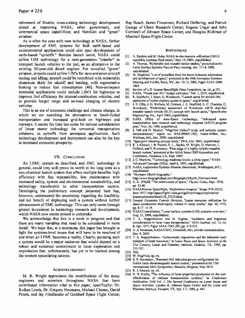
More recently, the authors and partners from industry and academia have developed EML tracks to test new linear motor designs. Speeds of 256 km/hr (159 mph) have been achieved on a 60-Hz double-sided linear induction motor (DSLIM) track 3.7 m (12 ft) long. Another system, 5.5 m (18 ft) long utilizing 300-Hz DSLIM's, was built to test speeds of approximately 322 km/hr (200 mph) (Fig. 1); static load-cell testing was performed, with peak thrust measured at 15.57 N (3,500 lb-t) [11]. With these demonstrations, a Technology Readiness Level (TRL) [12] of5 has been achieved.
Besides NASA, the U.S. Navy is developing an Electromagnetic Aircraft Launch System (EMALS) on aircraft carriers using EML technology to replace traditional steampowered catapults [13]. Internationally, electromagnetics
https://ntrs.nasa.gov/search.jsp?R=20110007073 2020-04-26T02:09:51+00:00Z

Paper # 229
technology has been utilized for full-scale surface transportation systems in Germany, China, and Japan. It has great potential within partnerships currently being established for NASA's new technology and future exploration programs.
Earth-based EML systems are good candidates for more efficient and sustainable launching of vehicles to space. One of the issues, of course, is that atmospheric drag and the deltav required to launch from earth require supplemental chemical-based rocket propulsion. The natural progression for this concept is a moon-based EML that could take advantage of both no atmosphere and lower gravity.
III. A TRIP FROM THE MOON: LUNAR EML
Several concepts of a lunar EML (LEML) system have been proposed over the years, from Hermann Oberth's "lunar catapult" [14] to Gerard O'Neill's "mass driver" that found its way into several colonization studies [15]. A detailed study conducted in the late 70's concluded that a lunar mass driver would be the optimal technology (compared to chemical rockets) to transport resources such as lunar material for inspace construction (Fig. 2) [16], [17].
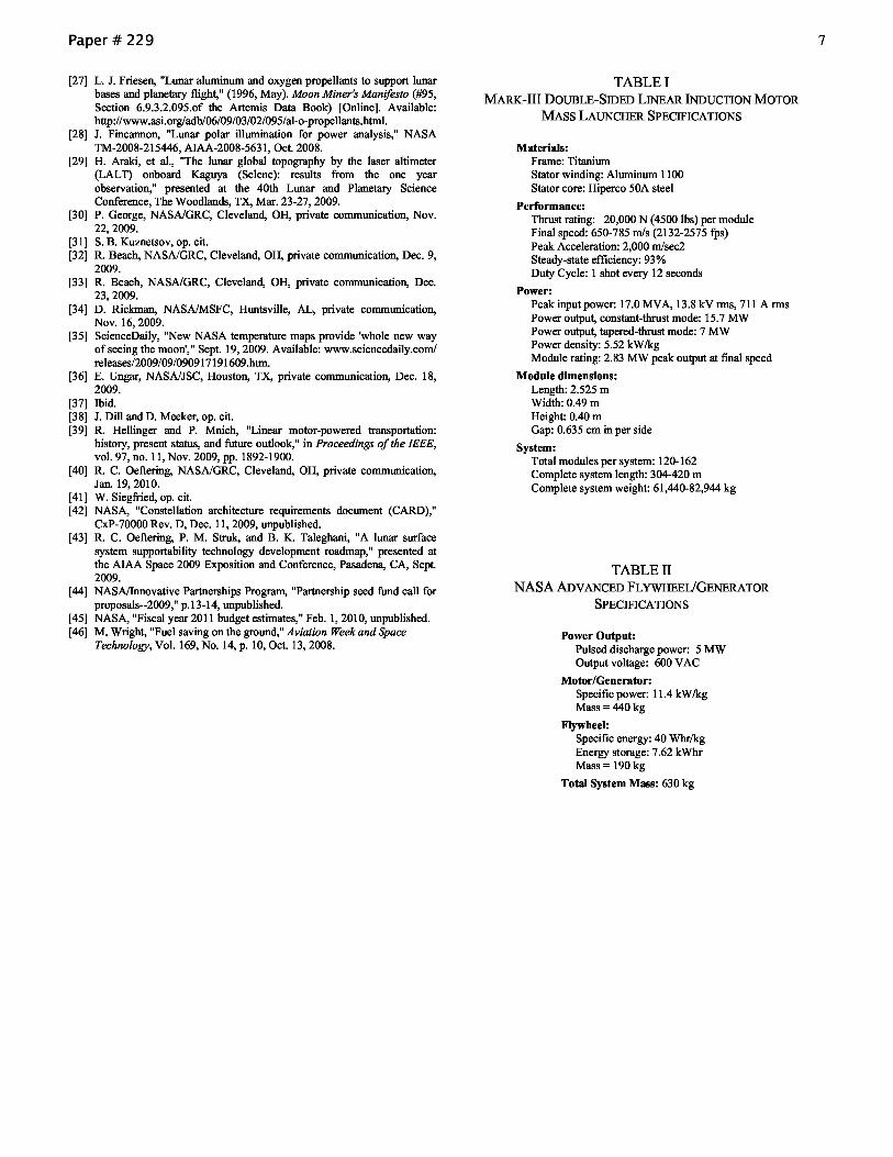
Here, we update the LEML concept based on what has been recently proposed for NASA exploration systems, and on higher-TRL technology using a more modest energy requirement. During the last few years, NASA has developed several "scenarios" for long-duration lunar exploration (Fig. 3) [18]. LEML would have broad application to future lunar exploration and settlement, such as enabling sample return and other logistics transport, and refueling in LEO or low-lunar orbit (LLO).
An LEML system would enable fast-cycle, incremental (e.g., a few kg) supplies oflunar-derived material to depots or reusable landers in LLO. Eliminating the requirement for a large quantity of explosive fuel on the lunar surface would be safer for both crew and infrastructure. An "assembly line" LEML system could be operated robotically to reduce or eliminate extravehicular activities (EVA's) required to prepare and launch payloads. There would also be no release of exhaust volatiles and high-velocity particles during launch, as is the case with chemical propulsion. The high safety and low maintenance of such a system would reduce the loss-ofcrew/loss-of-mission (LOCILOM) risks associated with launching commodities from the lunar surface.
For eventual missions to Mars, an established LEML could also support incremental fuel shipments to an earth departure stage (EDS). Several concepts for the ejected mass are conceivable, from a "dumb" fuel module injected to a LLO fuel depot and tanker-shuttle, to a small capsule for a direct moon-to-LEO trajectory enabled by on-board orbital maneuvering and attitude control systems (ACS). Incorporating subsystems like ACS and cryogenics hardware would, of course, require some additional mass overhead. Fortunately, another attribute of EML technology is its scalability as requirements demand and resources allow.
In summary, the benefits of LEML over other means of transporting samples, fuel, and other lunar commodities are obvious: reusability with fast cycle times (high launch rate), no hazardous fuel, no exhaust products, low maintenance,
2
robotic operability, and scalability. Despite these advantages, there are clearly several technical challenges which must be addressed before such a system can become viable.
IV. A REPRESENTATIVE CONCEPTUAL DESIGN
In order to develop a first-order assessment of the viability of an LEML system for ISRU applications, an example architecture is considered. This representative concept design is limited to rather conservative parameters in order to determine if even a modest architecture is feasible and how it compares with a representative heavy-lift capability. A detailed quantitative description of an LEML system is challenging due to the lack of any full-scale EML launches to date, the complexities involved in establishing and operating such a system on the moon, and the current uncertainties regarding future exploration architectures. Therefore, the description presented here of the proposed concept includes only top-level technical aspects with no attempt to estimate development schedule or cost of such a system.
A. Mission Destination
There are several mission destinations for lunar-launched materials worthy of consideration: earth, LLO, earth-moon LIIL2 and L4/5, Mars, and other extra-cislunar trajectories. In order to bound a first-order conceptual LEML design, the mission destination that seems most favorable for any proposed exploration program -- moon to earth-moon LIIL2 -is analyzed here in more detail.
Earth-moon LlIL2 affords a good route to supply a material depot, with only a modest increase in delta-v compared to that for LLO. It also allows launch sites at various locations, with no launch-critical time dependence. Although Ll is closer to earth and affords line-of-sight communications, an in-depth orbital analyses of LEML launch to an autonomous L2 depot has already been performed by Heppenheimer and Kaplan [19], and is more useful to illustrate this concept. Therefore, a design to launch material from the moon to a depot at the earth-moon L2 point (L2) is suggested, as only one of several potential applications ofEML to lunar exploration.
B. Assumptions
As mentioned earlier, designing a system that is as visionary and without precedence as LEML is a challenge. Despite this, first-order estimations are possible with assumptions based on previous studies, existing technology, and exploration systems architectures being considered for eventual deployment.
A representative LEML concept can be described based on the following assumptions: 1) Exploration systems capabilities, such as NASA's
Constellation architecture 2, will become available. 2) There will be a commissioned lunar surface infrastructure
to support long-term habitats and ISRU, including: resource mining, production, and handling; and power generation, storage, and distribution.
2 Although the Constellation program has been cancelled in the proposed FY 2011 NASA budget to date, the architecture designs are valid as a practical reference.
Paper # 229
3) There will be an established, on-going demand for resource-derived commodities from the lunar surface.
4) A depot at L2 will exist to autonomously receive and store incremental shipments of commodities.
5) Initial LEML construction will not depend on ISRU, i.e., will require materials and equipment from earth.
6) A direct or near-direct trajectory for incremental launches from a surface departure point to a depot at L2 is possible.
C. Site Location
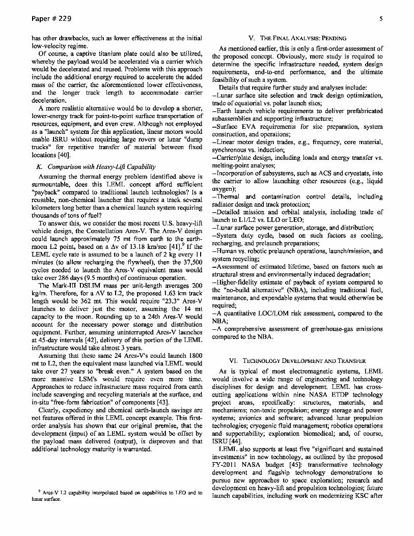
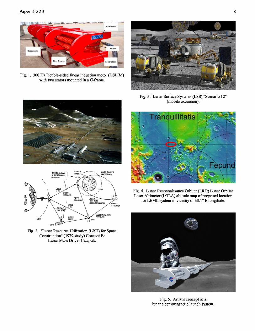
Although, the south pole has been identified as most promising for lunar settlement, a surface location that affords the most energy-efficient, direct injection to L2 is suggested for this example. Specifically, the equatorial site near 33.10 E longitude (Fig. 4) [20] has been proposed, with direct injections to L2 via "achromatic" trajectories possible from optimum sites on the lunar surface [21]. L2 is synchronized with the lunar surface, so the injection trajectory would be fixed and therefore good for LEML. In addition, this area is also selenographically conducive to an LEML launch site, and is considered a potential site for harvesting resources for fuel production, including oxygen, glass, and aluminum [22]. Given this launch point, the velocity required to reach L2 is 2.53 km/sec [23].
D. Linear Motor Design
To leverage experience with proven EML motor technology, this example is based on state-of-the-art, lowmass linear motor designs.3 The "Mark-III" DSLIM lightweight mass launcher has been designed for the Navy and is an advanced version of the motors developed by NASA. A summary of specifications for this design is shown in Table I. Linear induction (rather than synchronous) motors are preferred due to their relatively lower mass and magnet-free carrier design.
The Mark-III frames are titanium rather than steel, the windings are aluminum instead of copper, and the cores can run at a flux density twice that of existing linear induction motors (LIM's). Transverse-flux design realizes a weight reduction of one-third that of standard copper LIM's. Unlike most EML technology that has been proposed for lunar launch, this motor and others developed and tested by the authors are currently at a TRL-5 [25].
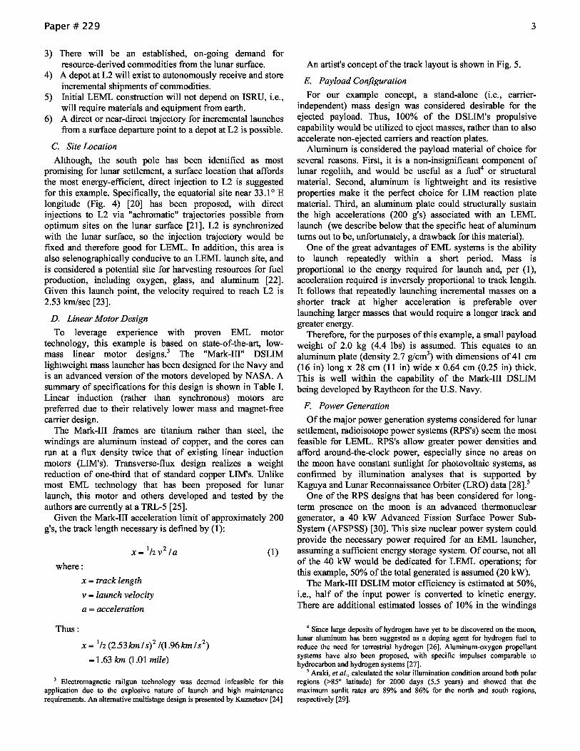
Given the Mark-III acceleration limit of approximately 200 g's, the track length necessary is defmed by (1):
where:
Thus:
x = track length
v = launch velocity
a = acceleration
x = 1 h (2.53 km 1 S)2 1(1.96 km 1 S2)
= 1.63 km (1.01 mile)
(1)
3 Electromagnetic railgun technology was deemed infeasible for this application due to the explosive nature of launch and high maintenance requirements. An alternative multistage design is presented by Kuznetsov [24]
3
An artist's concept ofthe track layout is shown in Fig. 5.
E. Payload Configuration
For our example concept, a stand-alone (i.e., carrierindependent) mass design was considered desirable for the ejected payload. Thus, 100% of the DSLIM's propulsive capability would be utilized to eject masses, rather than to also accelerate non-ejected carriers and reaction plates.
Aluminum is considered the payload material of choice for several reasons. First, it is a non-insignificant component of lunar regolith, and would be useful as a fuel4 or structural material. Second, aluminum is lightweight and its resistive properties make it the perfect choice for LIM reaction plate material. Third, an aluminum plate could structurally sustain the high accelerations (200 g's) associated with an LEML launch (we describe below that the specific heat of aluminum turns out to be, unfortunately, a drawback for this material).
One of the great advantages of EML systems is the ability to launch repeatedly within a short period. Mass is proportional to the energy required for launch and, per (1), acceleration required is inversely proportional to track length. It follows that repeatedly launching incremental masses on a shorter track at higher acceleration is preferable over launching larger masses that would require a longer track and greater energy.
Therefore, for the purposes of this example, a small payload weight of 2.0 kg (4.4 lbs) is assumed. This equates to an aluminum plate (density 2.7 g/cm3
) with dimensions of 41 cm (16 in) long x 28 cm (11 in) wide x 0.64 cm (0.25 in) thick. This is well within the capability of the Mark-III DSLIM being developed by Raytheon for the U.S. Navy.
F. Power Generation
Of the maj or power generation systems considered for lunar settlement, radioisotope power systems (RPS's) seem the most feasible for LEML. RPS's allow greater power densities and afford around-the-clock power, especially since no areas on the moon have constant sunlight for photovoltaic systems, as confirmed by illumination analyses that is supported by Kaguya and Lunar Reconnaissance Orbiter (LRO) data [28].5
One of the RPS designs that has been considered for longterm presence on the moon is an advanced thermonuclear generator, a 40 kW Advanced Fission Surface Power SubSystem (AFSPSS) [30]. This size nuclear power system could provide the necessary power required for an EML launcher, assuming a sufficient energy storage system. Of course, not all of the 40 kW would be dedicated for LEML operations; for this example, 50% of the total generated is assumed (20 kW).
The Mark-III DSLIM motor efficiency is estimated at 50%, i.e., half of the input power is converted to kinetic energy. There are additional estimated losses of 10% in the windings
4 Since large deposits of hydrogen have yet to be discovered on the moon, lunar aluminum has been suggested as a doping agent for hydrogen fuel to reduce the need for terrestrial hydrogen [26]. Aluminum-oxygen propellant systems have also been proposed, with specific impulses comparable to hydrocarbon and hydrogen systems [27].
5 Araki, et al., calculated the solar illumination condition around both polar regions (>85° latitude) for 2000 days (5.5 years) and showed that the maximum sunlit rates are 89% and 86% for the north and south regions, respectively [29].
Paper # 229
and 7% in power conversion6 and distribution, for a total efficiency of approximately 33%. Therefore, for the required delta-v, the total energy required would be:
where:
Thus:
E = launch energy
m = payload mass
v = delta-v
E= 1/2 (2kg)(2.531an/s)2
= 6.40MJx 3 (33% efficiency)
= 19.2MJ
G. Energy Storage
(2)
An energy storage system for LEML would need to concurrently meet the requirements for high energy density, near-instantaneous discharge, and environmental tolerance. Flywheel storage devices, commonly incorporated into terrestrial EML systems, offer high depth-of-discharge and long life despite angular speeds of up to 2 kmIhr.
A higher-energy lunar flywheel is feasible based on spacequalified systems developed for satellites, such as the NASA Glenn Research Center's G3 unit. These designs allow a smaller motor/generator and incorporate composite arbor technology to achieve a stiff large-rotor system [32].
To supply the needed 19.2 MJ, a flywheel energy storage system would be possible having the specs shown in Table II [33]. Assuming 20 kW of the AFSPSS were dedicated for LEML launch, it would take 16 minutes (19.2 MJ/20 kW) to store the energy to prepare for launch.
H Contamination Control
Ever since the Apollo landings, lunar regolith has been known for its fme and abrasive particulates. Dust with average size less than 20 micrometers is prevalent throughout the surface, but is only a problem for hardware when there is a direct path to surfaces [34].
Fortunately, LEML does not produce exhaust to kick up surface dust and, of course, there is no atmosphere to be affected by a high-speed wake. Therefore, contamination could be mitigated simply by ensuring that the track is protected from direct dust impingement through, for example, a baffle arrangement. It should be noted that the 7 mm (0.28 in.) gap of the LIM motor is 14,000 times the size of an average lunar dust particle; therefore, plate-to-track binding and abrasion are considered not credible.
1. Thermal Control
From the most recent LRO data, the thermal environment at the lunar equatorial region ranges from -183C (-298F) at night to +118C (244F) in daytime [35] and is, of course, nonconvective. This environment is therefore quite different from that on a Navy vessel for which the Mark-III DSLIM was designed. Low temperatures can be tolerated by the DSLIM,
6 Details of a proposed DSLIM power converter for lunar applications, as well as additional DSLIM details, may be found in Kusnetsov [31].
4
particularly with multi-layer insulation (MLI), mylar foil blankets, and/or supplemental heaters.
High temperatures, on the other hand, typically dictate active cooling for EML systems due to the high speeds and switching frequencies during launch. Operational heating for our concept LEML is estimated at approximately 1.92 MJ, i.e., 10% of the total energy. The size of the track (1.6 km long x 0.5 m wide x 0.4 m high) and its large exposed surface area enables some passive cooling through low-emissivity or highalbedo coatings (e.g., white paint).7 Further, the 7% loss in power conversion equates to a heat rejection requirement of 1.34 MJ. To put this in perspective, a radiator array that can dissipate about 4 kW of thermal energy has been proposed for a lunar habitat [37]. A radiator to dissipate over 1 MW of thermal energy would therefore be a significantly greater challenge.
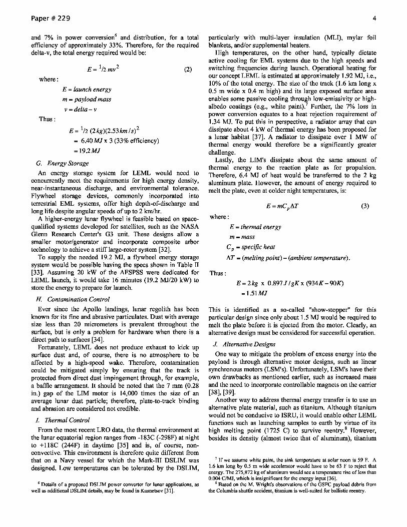
Lastly, the LIM's dissipate about the same amount of thermal energy to the reaction plate as for propulsion. Therefore, 6.4 MJ of heat would be transferred to the 2 kg aluminum plate. However, the amount of energy required to melt the plate, even at colder night temperatures, is:
where:
Thus:
E = thermal energy
m=mass
C p = specific heat
AT = (melting point) - (ambient temperature).
E= 2kg x 0.897J /gKx (934K -90K)
=1.51MJ
(3)
This is identified as a so-called "show-stopper" for this particular design since only about 1.5 MJ would be required to melt the plate before it is ejected from the motor. Clearly, an alternative design must be considered for successful operation.
J. Alternative Designs
One way to mitigate the problem of excess energy into the payload is through alternative motor designs, such as linear synchronous motors (LSM's). Unfortunately, LSM's have their own drawbacks as mentioned earlier, such as increased mass and the need to incorporate controllable magnets on the carrier [38], [39].
Another way to address thermal energy transfer is to use an alternative plate material, such as titanium. Although titanium would not be conducive to ISRU, it would enable other LEML functions such as launching samples to earth by virtue of its high melting point (1725 C) to survive reentry.8 However, besides its density (almost twice that of aluminum), titanium
7 If we assume white paint, the sink temperature at solar noon is 59 F. A 1.6 Ian long by 0.5 m wide accelerator would have to be 63 F to reject that energy. The 275,872 kg of aluminum would see a temperature rise of less than 0.004 CIMJ, which is insignificant for the energy input [36].
g Based on the M. Wright's observations of the GSFC payload debris from the Columbia shuttle accident, titanium is well-suited for ballistic reentry.
Paper # 229
has other drawbacks, such as lower effectiveness at the initial low-velocity regime.
Of course, a captive titanium plate could also be utilized, whereby the payload would be accelerated via a carrier which would be decelerated and reused. Problems with this approach include the additional energy required to accelerate the added mass of the carrier, the aforementioned lower effectiveness, and the longer track length to accommodate carrier deceleration.
A more realistic alternative would be to develop a shorter, lower-energy track for point-to-point surface transportation of resources, equipment, and even crew. Although not employed as a "launch" system for this application, linear motors would enable ISRU without requiring large rovers or lunar "dump trucks" for repetitive transfer of material between fixed locations [40].
K. Comparison with Heavy-Lift Capability
Assuming the thermal energy problem identified above is surmountable, does this LEML concept afford sufficient "payback" compared to traditional launch technologies? Is a reusable, non-chemical launcher that requires a track several kilometers long better than a chemical launch system requiring thousands of tons offuel?
To answer this, we consider the most recent U.S. heavy-lift vehicle design, the Constellation Ares-V. The Ares-V design could launch approximately 75 mt from earth to the earthmoon L2 point, based on a Iw of 13.18 km/sec [41].9 If the LEML cycle rate is assumed to be a launch of 2 kg every 11 minutes (to allow recharging the flywheel), then the 37,500 cycles needed to launch the Ares-V equivalent mass would take over 286 days (9 .5 months) of continuous operation.
The Mark-III DSLIM mass per unit-length averages 200 kg/m. Therefore, for a AV to L2, the proposed 1.63 km track length would be 362 mt. This would require "23.3" Ares-V launches to deliver just the motor, assuming the 14 mt capacity to the moon. Rounding up to a 24th Ares-V would account for the necessary power storage and distribution equipment. Further, assuming uninterrupted Ares-V launches at 45-day intervals [42], delivery of this portion of the LEML infrastructure would take almost 3 years.
Assuming that these same 24 Ares-V's could launch 1800 mt to L2, then the equivalent mass launched via LEML would take over 27 years to "break even." A system based on the more massive LSM's would require even more time. Approaches to reduce infrastructure mass required from earth include scavenging and recycling materials at the surface, and in-situ "free-form fabrication" of components [43].
Clearly, expediency and chemical earth-launch savings are not features offered in this LEML concept example. This firstorder analysis has shown that our original premise, that the development (input) of an LEML system would be offset by the payload mass delivered (output), is disproven and that additional technology maturity is warranted.
9 Ares-V L2 capability interpolated based on capabilities to LEO and to lunar surface.
5
V. THE FINAL ANALYSIS: PENDING
As mentioned earlier, this is only a first-order assessment of the proposed concept. Obviously, more study is required to determine the specific infrastructure needed, system design requirements, end-to-end performance, and the ultimate feasibility of such a system.
Details that require further study and analyses include: --Lunar surface site selection and track design optimization, trade of equatorial vs. polar launch sites; --Earth launch vehicle requirements to deliver prefabricated subassemblies and supporting infrastructure; --Surface EVA requirements for site preparation, system construction, and operations; --Linear motor design trades, e.g., frequency, core material, synchronous vs. induction; --Carrier/plate design, including loads and energy transfer vs. melting-point analyses; --Incorporation of subsystems, such as ACS and cryostats, into the carrier to allow launching other resources (e.g., liquid oxygen); --Thermal and contamination control details, including radiator design and track protection; --Detailed mission and orbital analysis, including trade of launch to LlIL2 vs. LLO or LEO; --Lunar surface power generation, storage, and distribution; --System duty cycle, based on such factors as cooling, recharging, and prelaunch preparations; --Human vs. robotic prelaunch operations, launch/mission, and system recycling; --Assessment of estimated lifetime, based on factors such as structural stress and environmentally induced degradation; --Higher-fidelity estimate of payback of system compared to the "no-build alternative" (NBA), including traditional fuel, maintenance, and expendable systems that would otherwise be required; --A quantitative LOCILOM risk assessment, compared to the NBA; --A comprehensive assessment of greenhouse-gas emissions compared to the NBA.
VI. TECHNOLOGY DEVELOPMENT AND TRANSFER
As is typical of most electromagnetic systems, LEML would involve a wide range of engineering and technology disciplines for design and development. LEML has crosscutting applications within nine NASA ETDP technology project areas, specifically: structures, materials, and mechanisms; non-toxic propulsion; energy storage and power systems; avionics and software; advanced lunar propulsion technologies; cryogenic fluid management; robotics operations and supportability; exploration biomedical; and, of course, ISRU [44].
LEML also supports at least five "significant and sustained investments" in new technology, as outlined by the proposed FY-2011 NASA budget [45]: transformative technology development and flagship technology demonstrations to pursue new approaches to space exploration; research and development on heavy-lift and propulsion technologies; future launch capabilities, including work on modernizing KSC after
Paper # 229
retirement of Shuttle; cross-cutting technology development aimed at improving NASA, other government, and commercial space capabilities; and NextGen and "green" aviation.
As is often the case with new technology at NASA, further development of EML systems for both earth-based and extraterrestrial applications could also spur development of earth-based "spinoffs." Besides launch assist, NASA could utilize LIM technology for a next-generation "crawler" to transport launch vehicles to the pad, as an alternative to the existing 50-year-old diesel engines. For so-called "green" aviation, airports could utilize LIM's for zero-emission aircraft taxiing and idling; aircraft could be retrofttted with retractable aluminum skids for takeoff and landing, with regenerative braking to reduce fuel consumption [46]. Non-aerospace terrestrial applications could include LIM's for highways to improve fuel efficiency for internal-combustion vehicles, and to provide longer range and on-road charging of electric vehicles.
This is an era of economic challenge and climate change, in which we are searching for alternatives to fossil-fueled transportation and increased grid-lock on highways and runways. It seems the time has come for serious consideration of linear motor technology for terrestrial transportation solutions, as spinoffs from aerospace applications. Such technology development and deployment can also be the key to increased economic prosperity.
VII. CONCLUSION
An LEML system as described, and EML technology in general, could very well prove its worth in the long term as a non-chemical launch system that offers multiple benefits: high efficiency with fast repeatability, low maintenance with increased safety, system and environmental sustainability, and technology transferable to other transportation sectors. Developing the preliminary concept presented here has, however, underscored the uncertainty regarding the feasibility and net benefit of deploying such a system without further advancement ofEML technology. This can only come through greater investment in technology research and development, which NASA now seems poised to undertake.
We acknowledge that this is a work in progress and that there are many variables that need to be considered in more detail. We hope that, at a minimum, this paper has brought to light the systems-level issues that will have to be resolved if and when an LEML becomes a reality. Clearly, pursuing such a system would be a major endeavor that would depend on a robust and sustained commitment to lunar exploration and exploitation that, unfortunately, has yet to be realized among the western space faring nations.
ACKNOWLEDGMENT
M. R Wright appreciates the contributions of the many engineers and scientists throughout NASA that have contributed information vital to this paper, specifically: Dr. Ruthan Lewis, Dr. Gregory Neumann, Michael Chesne, David Peters, and Jay Friedlander of Goddard Space Flight Center;
6
Ray Beach, James Fincannon, Richard Oeftering, and Patrick George of Glenn Research Center; Eugene Ungar and John Cornwell of Johnson Space Center; and Douglas Rickman of Marshall Space Flight Center.
REFERENCES
[1] G. Sanders and M. Duke, NASA in-situ resource utilization (ISRU) capability roadmap fmal report," May 19,2005, unpublished.
[2] A. Thomas, "Refuelable and reusable lander studies," presented at the Lunar Surface Systems Face-to-Face meeting, Jan. 12-14,2009, unpublished.
[3] W. Siegfried, "Use of propellant from the moon in human exploration and development of space," presented at the 38th Aerospace Sciences Meeting and Exhibit, Reno, NY, Jan. 10-13,2000, Paper AIAA-2000-1063.
[4] Review of U.S. Human Spaceflight Plans Committee, op. cit., p.101. [5] NASA, "Fiscal year 2011 budget estimates," Feb. 1,2010, unpublished. [6] R. Sackheim, J. Suter, G. Woodcock, "Launch assist for aircraft-like
operations of rocket airplane access to space," unpublished. [7] J. R. Olds, J. G. Wallace, M. Graham, J. E. Bradford, A. C. Charania, G.
Woodcock, "Preliminary assessment of Woodcock ARTS dual-fuel reusable launch vehicle (RLV) concept with launch assist," SpaceWorks Engineering, Inc., April 2003, unpublished.
[8] NASA Office of Aero-Space Technology, "Advanced space transportation base research and technology program (ASTP) program plan," Nov. 30, 1999, unpublished.
[9] J. Dill and D. Meeker, "Maglifter tradeoff study and subscale system demonstrations," report no. NAS-98069-1362, Foster-Miller, Inc., Waltham, MA, Dec. 2000, unpublished.
[10] "Spaceport visioning concept study," ZHA, Oct. 2002, unpublished. [11] K. J. Kloesel, J. B. Pickrel, E. L., Sayles, M. Wright, D. Marriott, L.
Holland, and S. Kuznetsov, "First stage of a highly reliable reusable launch system," presented at the AIAA Space 2009 Exposition and Conference, Pasadena, CA, Sept. 2009.
[12] J. C. Mankins, "Technology readiness levels: a white paper," NASA Advanced Concepts Office, April 6, 1995, unpublished.
[13] NASA, Exploration Systems Mission Directorate, Washington, D.C., unpublished.
[14] "Hermann Oberth biography," http://www.biographybase.comlbiography/Oberth _ Hermann.html.
[15] G. K. O'Neill, "The colonization of space," Physics Today, Sept. 1974, pp.32-40.
[16] NASA/Human Spaceflight, "Exploration imagery," Image S78-23252, June 1977, http://spaceflight l.nasa.gov/ gallery/images/exploration! lunarexplorationlhtml/s78 _ 23252.html.
[17] General Dynamics Convair Division, "Lunar resources utilization for space construction final report, volume II: study results," Apr. 30, 1979, pp. 4-17 - 4-19.
[18] NASA/Constellation, "Lunar surface systems (LSS) scenario overview," Aug. 31, 2009, unpublished.
[19] T. A. Heppenheimer and D. Kaplan, "Guidance and trajectory considerations in lunar mass transportation," AIAA Journal, vol. 15, no. 4, Apr. 1977, Paper AIAA-7345-392, pp. 518-525.
[20] G. A Neumann, NASA/GSFC, Greenbelt, MD, private communication, Dec. 8, 2009.
[21] T. A. Heppenheimer, "Achromantic trajectories and the industrial-scale transport of lunar resources," in Lunar Bases and Space Activities of the 21st Century, Lunar and Planetary Institute, Houston, TX, 1985, pp. 155-167.
[22] Ibid. [23] W. Siegfried, op. cit. [24] S. B. Kuznetsov, "Resonant link induction power configuration for
NASA lunar electromagnetic launch system," presented at the 15th International EML Symposium, Brussels, Belgium, May 2010.
[25] K. J. Kloesel, op. cit. [26] H. H. Koelle, "The influence of lunar propellant production on the cost
effectiveness of cislunar transportation systems," in Conference Publication 3166 Vol. 1, The Second Conference on Lunar Bases and Space Activities, Lyndon B. Johnson Space Center and the Lunar and Planetary Institute, Houston, TX, Apr. 5-7, 1988, p. 447.
Paper # 229
[27] L. J. Friesen, "Lunar aluminum and oxygen propellants to support lunar bases and planetary flight," (1996, May). Moon Miner's Manifesto (#95, Section 6.9.3.2.095.of the Artemis Data Book) [Online]. Available: http://www.asLorg/adb/06/09/03/02/095/al-o-propellants.html.
[28] J. Fincannon, "Lunar polar illumination for power analysis," NASA TM-2008-215446, AlAA-2008-5631, Oct. 2008.
[29] H. Araki, et aI., "The lunar global topography by the laser altimeter (LALT) onboard Kaguya (Selene): results from the one year observation," presented at the 40th Lunar and Planetary Science Conference, The Woodlands, TX, Mar. 23-27, 2009.
[30] P. George, NASA/GRC, Cleveland, OH, private communication, Nov. 22,2009.
[31] S. B. Kuznetsov, op. cit. [32] R. Beach, NASA/GRC, Cleveland, OH, private communication, Dec. 9,
2009. [33] R. Beach, NASA/GRC, Cleveland, OH, private communication, Dec.
23,2009. [34] D. Rickman, NASAlMSFC, Huntsville, AL, private communication,
Nov. 16,2009. [35] ScienceDaily, "New NASA temperature maps provide 'whole new way
of seeing the moon'," Sept. 19,2009. Available: www.sciencedaily.coml releases/2009/09/090917191609.htm.
[36] E. Ungar, NASA/JSC, Houston, TX, private communication, Dec. 18, 2009.
[37] Ibid. [38] J. Dill and D. Meeker, op. cit. [39] R. Hellinger and P. Mnich, "Linear motor-powered transportation:
history, present status, and future outlook," in Proceedings o/the IEEE, vol. 97, no. 11, Nov. 2009, pp. 1892-1900.
[40] R. C. Oeftering, NASA/GRC, Cleveland, OH, private communication, Jan. 19,2010.
[41] W. Siegfried, op. cit. [42] NASA, "Constellation architecture requirements document (CARD),"
CXP-70000 Rev. D, Dec. 11,2009, unpublished. [43] R. C. Oeftering, P. M. Struk, and B. K. Taleghani, "A lunar surface
system supportability technology development roadmap," presented at the AlAA Space 2009 Exposition and Conference, Pasadena, CA, Sept. 2009.
[44] NASAIlnnovative Partnerships Program, "Partnership seed fund call for proposals--2009," p.13-14, unpublished.
[45] NASA, "Fiscal year 2011 budget estimates," Feb. 1,2010, unpublished. [46] M. Wright, "Fuel saving on the ground," Aviation Week and Space
Technology, Vol. 169, No. 14, p. 10, Oct. 13,2008.
TABLE I MARK-III DOUBLE-SIDED LINEAR INDUCTION MOTOR
MASS LAUNCHER SPECIFICATIONS
Materials: Frame: Titanium Stator winding: Aluminum 1100 Stator core: Hiperco 50A steel
Performance: Thrust rating: 20,000 N (4500 lbs) per module Final speed: 650-785 m1s (2132-2575 ips) Peak Acceleration: 2,000 m1sec2 Steady-state efficiency: 93% Duty Cycle: 1 shot every 12 seconds
Power: Peak ioput power: 17.0 MVA, 13.8 kV rms, 711 Arms Power output, constant-thrust mode: 15.7 MW Power output, tapered-thrust mode: 7 MW Power density: 5.52 kW/kg Module rating: 2.83 MW peak output at fmal speed
Module dimensions: Length: 2.525 m Width: 0.49 m Height: 0.40 m Gap: 0.635 cm in per side
System: Total modules per system: 120-162 Complete system length: 304-420 m Complete system weight: 61,440-82,944 kg
TABLE II NASA Anv ANCED FL YWHEELIGENERATOR
SPECIFICATIONS
Power Output: Pulsed discharge power: 5 MW Output voltage: 600 V AC
Motor/Generator: Specific power: 11.4 kW/kg Mass = 440 kg
Flywheel: Specific energy: 40 Whr/kg Energy storage: 7.62 kWhr Mass = 190 kg
Total System Mass: 630 kg
7
Paper # 229
Fig. 1. 300 Hz Double-sided linear induction motor (DSLIM) with two stators mounted in a C-frame.
Fig. 2. "Lunar Resource Utilization (LRU) for Space Construction" (1979 study) Concept B:
Lunar Mass Driver Catapult.
Fig. 3. Lunar Surface Systems (LSS) "Scenario 12" (mobile excursion).
Fig. 4. Lunar Reconnaissance Orbiter (LRO) Lunar Orbiter Laser Altimeter (LOLA) altitude map of proposed location
for LEML system in vicinity of 33.1 0 E longitude.
Fig. 5. Artist's concept of a lunar electromagnetic launch system.
8