a linkstation quick reference guide - …„¢ mini quick reference guide b a c d e ... the...
TRANSCRIPT
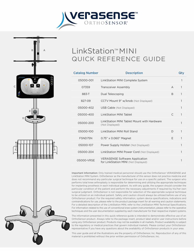
Catalog Number Description Qty
05000-001 LinkStation MINI Complete System 1
07359 Transceiver Assembly A 1
883-T Dual Telescoping B 1
827-09 CCTV Mount 9” w/knob (Not Displayed) 1
05000-402 USB Cable (Not Displayed) 1
05000-400 LinkStation MINI Tablet C 1
05000-200LinkStation MINI Tablet Mount with Hardware (Not Displayed)
1
05000-100 LinkStation MINI Roll Stand D 1
FSND75N 0.75” x 0.060” Magnet E 1
05000-107 Power Supply Holster (Not Displayed) 1
05000-204 LinkStation MINI Power Cord (Not Displayed) 1
05000-VRSEVERASENSE Software Application for LinkStation MINI (Not Displayed)
1
LinkStation™ MINIQUICK REFERENCE GUIDE
AB
C
D
E
Important Information: Only trained medical personnel should use the OrthoSensor VERASENSE and LinkStation MINI System. OrthoSensor as the manufacturer of this sensor does not practice medicine and does not recommend any particular surgical technique for use on a specific patient. The surgeon who performs total knee arthroplasty is responsible for determining and utilizing the appropriate techniques for implanting prosthesis in each individual patient. As with any guide, the surgeon should consider the particular condition of the patient and perform the necessary adjustments if required by his/her own surgical judgment. OrthoSensor is not responsible for selection of the appropriate surgical technique to be utilized on an individual patient. Safety and caution should always be utilized before use of any OrthoSensor product. For the required safety information, system device specifications, indications and contraindications for use, please refer to the product package insert for all warning and caution statements. For a detailed description of the LinkStation MINI, refer to the LinkStation MINI Technical Specifications. For information related to the use of conventional knee system instrumentation, please refer to the operative techniques and the user documentation supplied by each manufacturer for their respective implant systems.
The information presented in this quick reference guide is intended to demonstrate effective use of an OrthoSensor product. Always refer to the package insert, product label and/or user instructions before using any OrthoSensor product. Products may not be available in all markets. Product availability is subject to the regulatory or medical practices that govern individual markets. Please contact your OrthoSensor representative if you have any questions about the availability of OrthoSensor products in your area.
This user guide and all the illustrations are the property of OrthoSensor, Inc. Reproduction of any of this material is prohibited without the prior written permission of OrthoSensor, Inc.
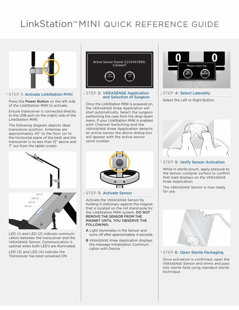
STEP 1: Activate LinkStation MINI
Press the Power Button on the left side of the LinkStation MINI to activate.
Ensure transceiver is connected directly to the USB port on the (right) side of the LinkStation MINI.
The following diagram depicts ideal transceiver position. Antennas are approximately 45° to the floor (or to the horizontal plane of the bed) and the transceiver is no less than 12” above and 7” out from the tablet screen.
STEP 5: Verify Sensor Activation
While in sterile pouch, apply pressure to the Sensor condylar surface to confirm that load displays on the VERASENSE Knee Application.
The VERASENSE Sensor is now ready for use.
STEP 6: Open Sterile Packaging
Once activation is confirmed, open the VERASENSE Sensor and shims and pass into sterile field using standard sterile technique.
STEP 2: VERASENSE Application and Selection of Surgeon
Once the LinkStation MINI is powered on, the VERASENSE Knee Application will start automatically. Select the surgeon performing the case from the drop-down menu. If your LinkStation MINI is enabled with Channel Switching and the VERASENSE Knee Application detects an active sensor the above dialog box will appear with the active sensor serial number.
STEP 3: Activate Sensor
Activate the VERASENSE Sensor by holding it stationary against the magnet that is located on the roll stand pole for the LinkStation MINI system. DO NOT REMOVE THE SENSOR FROM THE MAGNET UNTIL YOU OBSERVE THE FOLLOWING:
A Light illuminates in the Sensor and turns off after approximately 4 seconds.
B VERASENSE Knee Application displays the message Initialization Communi-cation with Device.
STEP 4: Select Laterality
Select the Left or Right Button.
LED (1) and LED (2) indicate communi-cation between the transceiver and the VERASENSE Sensor. Communication is optimal when both LED’s are illuminated.
LED (3) and LED (4) indicate the Transceiver has been powered ON.
LinkStation™ MINI QUICK REFERENCE GUIDE
Active Sensor found (1234567890).Connect?
LED (1)
LED (2)
LED (3)
LED (4)
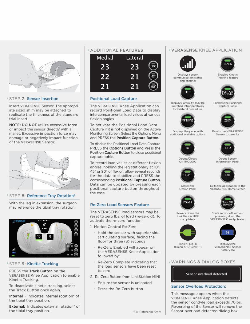
STEP 8: Reference Tray Rotation*
With the leg in extension, the surgeon may reference the tibial tray rotation.
STEP 9: Kinetic Tracking
PRESS the Track Button on the VERASENSE Knee Application to enable Kinetic Tracking.
To deactivate kinetic tracking, select the Track Button once again.
Internal - Indicates internal rotation* of the tibial tray position.
External: Indicates external rotation* of the tibial tray position.
STEP 7: Sensor Insertion
Insert VERASENSE Sensor. The appropri-ate sized shim may be attached to replicate the thickness of the standard trial insert.
NOTE: DO NOT utilize excessive force or impact the sensor directly with a mallet. Excessive impaction force may damage or negatively impact function of the VERASENSE Sensor.
*For Reference Only
ADDITIONAL FEATURES
Positional Load Capture
The VERASENSE Knee Application can record Positional Load Data to display intercompartmental load values at various flexion angles.
To activate the Positional Load Data Capture if it is not displayed on the Active Monitoring Screen. Select the Options Menu and PRESS the Position Capture Button.
To disable the Positional Load Data Capture PRESS the Options Button and Press the Position Capture Button to close positional capture table.
To record load values at different flexion angles, holding the leg stationary at 10°, 45° or 90° of flexion, allow several seconds for the data to stabilize and PRESS the corresponding Positional Capture Button. Data can be updated by pressing each positional capture button throughout the case.
Re-Zero Load Sensors Feature
The VERASENSE load sensors may be reset to zero lbs. of load (re-zero’d). To activate the re-zero function:
1. Motion Control Re-Zero
• Hold the sensor with superior side (articulating surface) facing the floor for three (3) seconds
• Re-Zero Enabled will appear on the VERASENSE Knee Application, followed by:
• Re-Zero Complete indicating that the load sensors have been reset to zero
2. Re-Zero Button from LinkStation MINI
• Ensure the sensor is unloaded
• Press the Re-Zero button
Medial
232221
Lateral
232121
VERASENSE KNEE APPLICATION
Displays the panel with additional available options
Resets the VERASENSE Sensor to zero lbs
Sensor overload detected
Sensor Overload Protection:
This message appears when the VERASENSE Knee Application detects the sensor condyle load exceeds 70lbs. Re-zeroing of the Sensor will remove the Sensor overload detected dialog box.
WARNINGS & DIALOG BOXES
Displays laterality, may be switched intraoperatively for bilateral procedure.
Enables the Positional Capture Table
Opens/Closes ORTHOLOIQ
Opens Sensor Information Panel
Closes the Option Panel
Exits the application to the VERASENSE Home Screen
Powers down the LinkStation MINI
completely
Shuts sensor off without powering down the
VERASENSE Knee Application
Enables Kinetic Tracking feature
Displays sensor communication status
and channel
5
Displays the VERASENSE Sensor
battery life
Tablet Plug-In (Green AC / Red DC)
WARNINGS & DIALOG BOXES
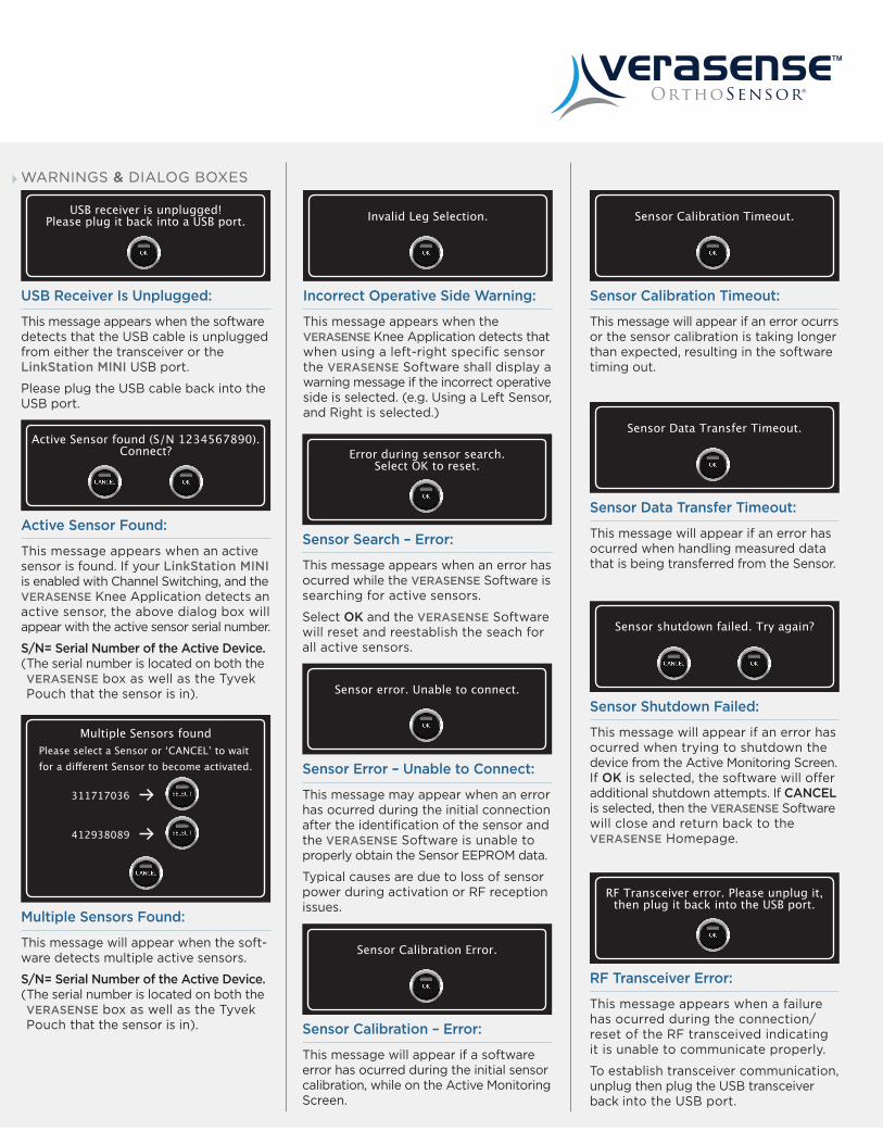
Incorrect Operative Side Warning:
This message appears when the VERASENSE Knee Application detects that when using a left-right specific sensor the VERASENSE Software shall display a warning message if the incorrect operative side is selected. (e.g. Using a Left Sensor, and Right is selected.)
Invalid Leg Selection.
Sensor Search – Error:
This message appears when an error has ocurred while the VERASENSE Software is searching for active sensors.
Select OK and the VERASENSE Software will reset and reestablish the seach for all active sensors.
Error during sensor search.Select OK to reset.
Sensor Error – Unable to Connect:
This message may appear when an error has ocurred during the initial connection after the identification of the sensor and the VERASENSE Software is unable to properly obtain the Sensor EEPROM data.
Typical causes are due to loss of sensor power during activation or RF reception issues.
Sensor error. Unable to connect.
Sensor Calibration Timeout:
This message will appear if an error ocurrs or the sensor calibration is taking longer than expected, resulting in the software timing out.
Sensor Calibration Timeout.
Sensor Data Transfer Timeout:
This message will appear if an error has ocurred when handling measured data that is being transferred from the Sensor.
Sensor Data Transfer Timeout.
RF Transceiver Error:
This message appears when a failure has ocurred during the connection/reset of the RF transceived indicating it is unable to communicate properly.
To establish transceiver communication, unplug then plug the USB transceiver back into the USB port.
RF Transceiver error. Please unplug it,then plug it back into the USB port.
Active Sensor Found:
This message appears when an active sensor is found. If your LinkStation MINI is enabled with Channel Switching, and the VERASENSE Knee Application detects an active sensor, the above dialog box will appear with the active sensor serial number.
S/N= Serial Number of the Active Device. ( The serial number is located on both the VERASENSE box as well as the Tyvek Pouch that the sensor is in).
Active Sensor found (S/N 1234567890).Connect?
Sensor Shutdown Failed:
This message will appear if an error has ocurred when trying to shutdown the device from the Active Monitoring Screen. If OK is selected, the software will offer additional shutdown attempts. If CANCEL is selected, then the VERASENSE Software will close and return back to the VERASENSE Homepage.
Sensor shutdown failed. Try again?
Multiple Sensors Found:
This message will appear when the soft- ware detects multiple active sensors.
S/N= Serial Number of the Active Device. ( The serial number is located on both the VERASENSE box as well as the Tyvek Pouch that the sensor is in).
Please select a Sensor or ‘CANCEL’ to wait for a different Sensor to become activated.
311717036
412938089
Multiple Sensors found
Sensor Calibration Error.
Sensor Calibration – Error:
This message will appear if a software error has ocurred during the initial sensor calibration, while on the Active Monitoring Screen.
USB Receiver Is Unplugged:
This message appears when the software detects that the USB cable is unplugged from either the transceiver or the LinkStation MINI USB port.
Please plug the USB cable back into the USB port.
USB receiver is unplugged!Please plug it back into a USB port.
CLEANING & CARE TROUBLESHOOTING
LinkStation MINI Tablet:
Use only a soft, lint-free cloth. Please Note: Abrasive cloths, towels, paper towels or similar items should not be used as these may cause damage to the LinkStation MINI.
1. Disconnect the LinkStation MINI Tablet from any external power sources.
2. Spray approved cleaner/disinfectant onto soft lint-free cloth. Do not spray cleaner/disinfectant directly onto equipment or at any openings.
3. Wipe surface until clean.
4. Cleaning of the LinkStation MINI tablet should be performed after each use.
LinkStation MINI Roll Stand:
1. The LinkStation MINI roll stand mounting assembly may be cleaned with most mild, non-abrasive solutions commonly used in the hospital environment (e.g. diluted bleach, ammonia, or isopropyl alcohol).
* Please Note: The surface finish will be permanently damaged by strong chemicals and solvents such as acetone and trichloro- ethylene; do not use steel wool or other abrasive material to clean the mounting assembly.
Never submerge or allow liquids to enter the mounting assembly. Wipe any cleaning agents off the mounting assembly immediately using a water-dampened cloth. Dry all mounting assemblies thoroughly after cleaning.
LinkStation MINI Transceiver:
1. Wipe the LinkStation MINI Transceiver down with 70% isopropyl alcohol wipes after each use.
LinkStation MINI Operating & Storage Temperature:
Operating Temperature: -10°C to 55°C
Storage Temperature: -51°C to 71°C
Relative Humidity: 5% to 95% noncondensing
VERASENSE Sensor:
If Sensor Light Does Not Turn Off During Activation:
• Return the sensor to the activation magnet to complete the activation sequence
If Sensor is showing no load values in the knee, or load values are being shown when it has been removed from the knee and no load is being applied:
• Re-Zero Sensor
LinkStation MINI Transceiver:
If Intermittent RF communication:
• Verify USB cable for the transceiver is securely plugged into the LinkStation MINI tablet and to the USB port on the bottom of the transceiver assembly
• Ensure antennas on the transceiver are secure and that the line of sight between the transceiver and the sensor is clear
• Objects such as OR lights, table, mayo stands or people can potentially interfere with communication
• All four LED lights on the transceiver will be illuminated when the Sensor is communicating
LinkStation MINI Tablet:
If LinkStation MINI Tablet will not turn on, or shut down inadvertently:
• Ensure that power cord is properly attached to the LinkStation MINI Tablet and plugged into power outlet
If LinkStation MINI Tablet power button is blinking but nothing is happening:
• The LinkStation MINI Tablet is in sleep mode. Press the power button to wake up the LinkStation MINI Tablet
LinkStation MINI Roll Stand:
If LinkStation MINI Roll Stand will not roll:
• Check to ensure that the breaks on the casters are disengaged.
Periodically inspect all fasteners
associated with the LinkStation MINI.
Ensure to tighten as necessary for
optimal operation and safety.
ROUTINE MAINTENANCE

OS-VS-16-0162 Rev 3
www.OrthoSensor.com | [email protected]
Tel +1 888.75.ORTHO (+1 888.756.7846) | Tel +1 954.577.7770 | Fax +1 954.337.9222
OrthoSensor, Inc. | 1855 Griffin Road, Suite A-310 | Dania Beach, Florida 33004 USA