a lightweight, modular robotic vehicle for the sustainable ... · pdf filea lightweight,...
TRANSCRIPT

Proceedings of Australasian Conference on Robotics and Automation, 2-4 Dec 2014, The University of Melbourne, Melbourne, Australia
A Lightweight, Modular Robotic Vehicle for the Sustainable Intensification of Agriculture
Owen Bawden, David Ball, Jason Kulk, Tristan Perez, Ray Russell
School of Electrical Engineering and Computer Science Queensland University of Technology
Garden's Point, Queensland, 4000 Australia (o.bawden, david.ball)@qut.edu.au
Abstract
This paper describes a lightweight, modular and energy efficient robotic vehicle platform designed for broadacre agriculture - the Small Robotic Farm Vehicle (SRFV). The current trend in farming is towards increasingly large machines that optimise the individual farmer’s productivity. Instead, the SRFV is designed to promote the sustainable intensification of agriculture by allowing farmers to concentrate on more important farm management tasks. The robot has been designed with a user-centred approach which focuses the outcomes of the project on the needs of the key project stakeholders. In this way user and environmental considerations for broadacre farming have informed the vehicle platform configuration, locomotion, power requirements and chassis construction. The resultant design is a lightweight, modular four-wheeled differential steer vehicle incorporating custom twin in-hub electric drives with emergency brakes. The vehicle is designed for a balance between low soil impact, stability, energy efficiency and traction. The paper includes modelling of the robot’s dynamics during an emergency brake in order to determine the potential for tipping. The vehicle is powered by a selection of energy sources including rechargeable lithium batteries and petrol-electric generators.
1 Introduction Over the coming decades, increases in demand for food from both new and traditional sources will put growing pressure on agricultural resources. Strong competition for land and water will come from housing, industry and the preservation of natural habitats for maintaining biodiversity. Agriculture production must also adapt to the unpredictable consequences of climate change [National Farmers Federation, 2013]. It is foreseeable that climate change will lead to increasing pressure on the supply side of agriculture, known as Supply Side Shocks, from rising frequency of draughts and floods.
For the past century agricultural productivity growth
has been achieved through farm consolidation leading to greater economies of scale, increased mechanization, crop improvements through accelerated breeding and genetic modification. These trends in agricultural practices will challenge farmers to meet the demands for future food production without severely detrimental environmental effects. For production increases to occur, farmers must either increase production efficiencies per hectare or per unit of key inputs such as fertilizer and water.
Increased agricultural production depends upon vehicle traffic. Modern production practices require tractors and combines to plant, manage and harvest agricultural crops. However, as vehicles have become progressively larger, they have increased their damage to the soil. Soil compaction has many detrimental effects on soil properties important to soil workability [Raper, 2005]. This includes poor drainage, which can lead to increased surface runoff and top-soil erosion, occurring by impeding water infiltration. Farmers must often balance the desire to tend crops, particularly after periods of rain when weed growth is most intense [Smart, 2013], with the ramifications of soil compaction from heavy vehicles.
In this paper we present the design of a Small Robotic Farm Vehicle (SRFV) which is shown in Figure 1. The lightweight and energy efficient robotic vehicle has a configurable, modular design, enabling interchangeable implement units to span between the modular side units. This modular design allows the SRFV to undertake a range of agricultural tasks and experiments, including harvesting, seeding, fertilizing and weeding management. The robot is designed to be more than an order of magnitude lower in weight than existing broadacre agricultural equipment.
Figure 1. Front perspective rendering of the SRFV.
Proceedings of Australasian Conference on Robotics and Automation, 2-4 Dec 2014, The University of Melbourne, Melbourne, Australia
The introduction of robotics in agriculture is seen as a
revolutionary step away from the current direction of improved productivity through greater precision on ever larger machines. Moving away from larger agricultural machines towards fleets of smaller autonomous vehicles is a paradigm shift in agriculture that is seen as having the following benefits: • Lighter impact on the environment. • Reduced occurrence of soil compaction. • Multi-purpose platform for weed mitigation, crop
scouting, seeding, fertilizing and harvesting. • More manoeuvrable platform, reducing the amount of
unused land. • Scalable, allowing farmers to utilise robots on farms
of all sizes. • No single point of failure (multi-robot redundancy). • Improve yields on existing land whilst allowing for the
economical cultivation of marginal land. • Lower vehicle and implement stresses, reducing the
complexity of the engineering and the overall cost. • Variable rate application of inputs for weed
mitigation. • Multi-mode weed management (chemical,
mechanical, electrical-thermal). • Smaller, more precise implements, capable of targeted
operations. • Long endurance throughout the diurnal cycle
(Day/Night). • Reduced labour demands.
Zero-tillage is widely regarded as best practice in Australian broadacre farming. For farmers, the fundamental benefits of zero-till agriculture have been limited soil disturbance resulting in reduced erosion, permanent ground cover leading to greater moisture retention, reduced fuel costs and reduced soil compaction [GRDC, 2010]. However, the nature of the zero-tillage requires greater use of herbicides to mitigate weeds and this has led to increased herbicide resistance in weeds in many areas of the country [Smart, 2013].
Weeds cost Australian agriculture around $4 Billion dollars a year [Sinden et al., 2004]. Since the 1990’s, with the introduction of glyphosate herbicides, such as Roundup, and their tremendous effectiveness, there has been a decrease in the investment in new technologies for weed mitigation. No major new site-of-action herbicide has been introduced into the marketplace in the last 20 years [Beckie and Tardif, 2012]. With the ability to control weeds successfully with herbicide alone rapidly running out, there needs to be a change to weed management.
Farmers are using more herbicide with less effect [Preston, 2013]. It is estimated in Australia that herbicide resistance is costing $200 million annually and rising [Smart, 2013]. Costs are much higher in the United States and other countries. Losses are occurring in production efficiency because farmers are now forced to spray resistant weeds multiple times or use tillage to remove weeds which effect the conservation of topsoil nutrients and moisture protected through zero-tillage agricultural practices [Hobbs, 2007].
The following section reviews the literature in agricultural robot platform design. Section 3 describes the requirements, objectives and specifications for the design of the SRFV. This is followed by the selection on the vehicle configuration, the design of the locomotion system
and then the chassis. The paper finishes with a conclusion.
2 Literature There has been a large amount of research into designing vehicles appropriate for agricultural robots. So far, robotics has been slow in the translation to farming because of the unstructured environment of biological production processes and the inherent variability of biological systems [Day, 2010]. Other challenges include the cost of mechanical technology, limited capacity and potential legal risks [Kassler, 2001].
The work of Madsen & Jakobsen [2001], Astrand et al. [2002] Jensen et al. [2012] and Bakker et al. [2009], among others, describe the design of autonomous platforms, predominantly for robotic weeding. Their design approach has varied to the considerations of traction, steering, dimensions, power-supply and control architecture.
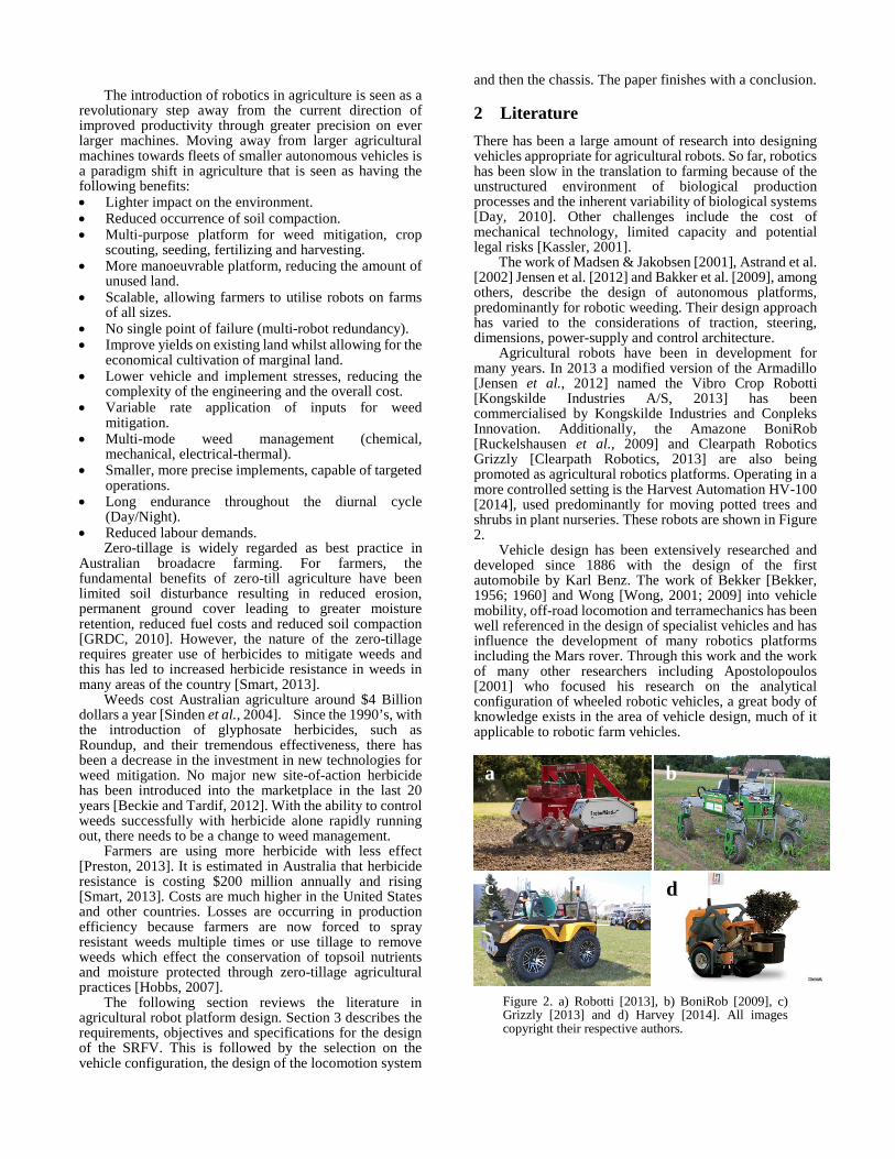
Agricultural robots have been in development for many years. In 2013 a modified version of the Armadillo [Jensen et al., 2012] named the Vibro Crop Robotti [Kongskilde Industries A/S, 2013] has been commercialised by Kongskilde Industries and Conpleks Innovation. Additionally, the Amazone BoniRob [Ruckelshausen et al., 2009] and Clearpath Robotics Grizzly [Clearpath Robotics, 2013] are also being promoted as agricultural robotics platforms. Operating in a more controlled setting is the Harvest Automation HV-100 [2014], used predominantly for moving potted trees and shrubs in plant nurseries. These robots are shown in Figure 2.
Vehicle design has been extensively researched and developed since 1886 with the design of the first automobile by Karl Benz. The work of Bekker [Bekker, 1956; 1960] and Wong [Wong, 2001; 2009] into vehicle mobility, off-road locomotion and terramechanics has been well referenced in the design of specialist vehicles and has influence the development of many robotics platforms including the Mars rover. Through this work and the work of many other researchers including Apostolopoulos [2001] who focused his research on the analytical configuration of wheeled robotic vehicles, a great body of knowledge exists in the area of vehicle design, much of it applicable to robotic farm vehicles.
Figure 2. a) Robotti [2013], b) BoniRob [2009], c) Grizzly [2013] and d) Harvey [2014]. All images copyright their respective authors.
a b
c d

Proceedings of Australasian Conference on Robotics and Automation, 2-4 Dec 2014, The University of Melbourne, Melbourne, Australia
3 Vehicle design Prior to developing the general specification for the vehicle (outlined in table 1 below) an extensive list of functional requirements were developed based on research from farm visits, analysis of literature and practical experimentation. These requirements covered:
• Environmental considerations, • Vehicle operation, • Ergonomics, • Ingress and chemical protections, • Enclosure requirements, • Vehicle dimensional and weight requirements, • Payload capacity, • Materials suitability, • Production and manufacturing logistic and costs, • Safety and, • Cleaning and maintenance In addition to these functional requirements, five key
objectives were defined to inform the design process for the vehicle. 1. Provide good driving ability on agricultural terrain. 2. Design a strong, yet lightweight vehicle to minimise
soil compaction. 3. Create a modular chassis design with interchangeable
components. 4. Design the vehicle to be low cost and easily
manufacturable. 5. Design the vehicle to be safe, mechanically reliable
and easy to maintain for the user. Table 1 below outlines the target specifications for the
vehicle. Research into appropriate payload capacity, along with common crop heights and row widths informed the vehicle’s specification. Assumptions were made on the importance of wind resistance, approximate centre of gravity, rolling resistance and overall vehicle dimensions. These are confirmed in later sections.
Table 1: Vehicle specifications
Vehicle Specification Measurement Unit Vehicle mass 400 kg Payload 200 kg Total vehicle mass 600 kg Rated speed 5 km/hr Max. speed 10 km/hr Acceleration 2 m/s² Width 3 m Length 2 m Operating time 10 hrs Drive wheel diameter 0.660 m Operating gradient 15 deg Emergency brakes required
4 Vehicle configuration Approximately 30 vehicle configurations including both tracked and wheeled variants were analysed and tested as scale models and rated in a matrix against a series of specific performance criteria including:
• Traversability, traction and soil disturbance, • Stability, • Manoeuvrability, • Modularity,
• Number of driving motors, and • Number of steering motors.
This analysis culled the list into a small selection of appropriate vehicle configurations for further more detailed analysis. The configurations shown in Figure 3 below encompass a wide range of possible wheel, motor, steering system and traction capabilities.
Figure 3. Schematics of the vehicle configurations that were considered in detail. These include (4) a tri-cycle, (9)-(16) differential steer with increasing numbers of motors, (11) Ackermann steer, and (18) differential tracked design.
4.1 Traction During the preliminary vehicle design and specification stage of the project, the relative performance characteristics of tyres and tracks were compared in agricultural soil conditions. Tracked vehicles offer many advantages over wheeled vehicles in off-road environments. Tracked vehicles increase traction and off-road traversability through their larger soil contact area. High pull ratios can also be obtained due to track grouser penetration and low ground contact pressures. Furthermore, the larger surface contact area of tracks reduces soil compaction by distributing the weight of the vehicle more evenly over a larger area.
As tracks have greater contact area, they have increased rolling resistance and therefore lower locomotive efficiency. Tracked vehicles also increase the weight and mechanical complexity of the vehicle and generally have a higher total operating cost than wheeled vehicles of equal power. Vehicles designed with tracks for locomotion generally manoeuvre using skid-steer which enables tight turning circles but increases soil disturbance over wheeled vehicles. These factors determined that a wheeled vehicle configuration would be more appropriate for broadacre applications.

Proceedings of Australasian Conference on Robotics and Automation, 2-4 Dec 2014, The University of Melbourne, Melbourne, Australia
4.2 Stability In all circumstances, stability is a major factor in vehicle design and configuration. Three-wheeled vehicles benefit from a reduced number of components, however, will have reduced stability compared to four-wheeled vehicles. A four-wheeled vehicle was chosen as the most suitable configuration because of its increased stability with four points of contact and larger payload carrying capacity.
4.3 Manoeuvrability The areas in Australia in which broadacre crops are grown vary widely. On larger farming operations, fields cultivated for wheat and other broadacre crops can stretch for many kilometres in unbroken tracks of land. Vehicles operating in this environment spend a large portion of their operating time traversing in relatively straight lines along crop rows to give even coverage to the entire area.
Manoeuvrability around headlands and between fields is undertaken only a small percentage of the operating time. Being able to drive consistently straight, and navigate successfully between crop rows is the main priority.
Vehicles with differential drive have superior manoeuvrability over Ackermann steer for the same number of motors.
4.4 Assessment of vehicle tipping Due to the high payload position and short wheel base of the concept design for the SRFV, we analysed the likelihood of the vehicle tipping over at steep operating angles. Trailer loading/unloading and steep downhill descents were treated as such opportunities.
The vehicle is considered to be a rigid body with a known location of the centre of mass. At the point of braking, the front wheels are assumed not to slip. The effect of the suspension on the the centre of mass could be significant bringing it forward and down. This effect would make the vehicle less likely to tip and so suspension is neglected from the model.
Consider the scenario depicted in Figure 4. The vehicle is traversing down a slope. The point of contact between the front wheel and the road is denoted by 𝑃. This is also the point about which the vehicle is assumed to pivot during a sudden emergency event - the motion of the point along the slope is neglected, and thus 𝑃 is assumed to be fixed. The centre of mass is identified with the point 𝐶 and the vehicle is assumed to have a mass 𝑚. At the point of braking, the vehicle traverses along the slope at a velocity �⃗� and speed 𝑣 = |�⃗�| parallel to the slope.
Based on the modelling hypothesis, tipping occurs whenever point 𝐶 is forward of point 𝑃 in the coordinate system {0} . The vector 𝑟𝐶/𝑃 denotes the position of 𝐶 relative to 𝑃. At the point of braking, the norm of this vector takes into account that the suspension has been compressed.
Figure 4. Idealised model of the vehicle physical
system for the tipping calculations.
4.4.1 State-space model We consider two right-handed coordinate systems fixed to Earth frame, namely {0} and {1} . As a generalised coordinate and first state variable, we choose the angle 𝜃 of rotation about the 𝑦-axis (out of the page) of the line segment 𝑃-𝐶 . Then, the condition for tipping becomes 𝜃 − 3
2𝜋 > 0 (𝜃 > 270∘)
As a second state variable, we choose the magnitude angular momentum of the centre of mass about the point 𝑃, namely 𝐿 = |𝐿�⃗ |. Then, a state-space model for system is
�̇� = 𝐽−1𝐿, (1) �̇� = 𝑚𝑔𝑙cos𝜃 − 𝑇𝑓(𝐽−1𝐿), (2) where 𝑙 = |𝑟𝐶/𝑃| is the arm, 𝑔 is the acceleration of
gravity and 𝐽 = 𝑚𝑙2 is the moment inertia of the centre of mass about 𝑃 . There is a friction torque 𝑇𝑓 which is associated with the rolling resistance of the wheel. This is modelled as Coulomb friction, which is consistent with automotive literature [Jazar, 2008]. The resistance force in translation for vehicle moving at low speeds can be modelled as follows [Jazar, 2008]:
𝐹𝑓 = −𝜇0𝑚𝑔cos(𝛾) 𝑣1|𝑣1|
, where 𝑣1 denotes the component of the velocity
along the 𝑥1-direction in {1}. Then, the rolling resistance torque in (2) can be modelled as
𝑇𝑓 = 𝑟𝑤𝜇0𝑚𝑔cos(𝛾) �̇�|�̇�|
, where 𝑟𝑤 is the radius of the wheel. In order to simulate (1)-(2) and ascertain whether a
vehicle may tip over, we need to find the initial conditions for 𝜃 and 𝐿.
4.4.2 Initial conditions The angular momentum of the centre of mass is
𝐿�⃗ (𝑡) = 𝑟𝐶/𝑃(𝑡) × 𝑚 �⃗�(𝑡) We can express these vectors in the {0} coordinate
system: 𝐋0 = 𝐒(𝐫𝐶/𝑃
0 ) 𝐯0 𝑚, that is
�0𝐿0(𝑡)0
� =
⎣⎢⎢⎢⎡0 −𝑧𝐶/𝑃
0 (𝑡) 0𝑧𝐶/𝑃0 (𝑡) 0 −𝑥𝐶/𝑃
0 (𝑡)0 𝑥𝐶/𝑃
0 (𝑡) 0⎦⎥⎥⎥⎤ ��̇�𝐶0(𝑡)0�̇�𝐶0(𝑡)
�𝑚 (3)
Then, 𝐿(𝑡) = 𝐿0(𝑡) = 𝑚 (𝑧𝐶/𝑃
0 (𝑡) �̇�𝐶0(𝑡) − 𝑥𝐶/𝑃0 (𝑡) �̇�𝐶0(𝑡))
(4) This equation evaluated at 𝑡 = 0 gives the initial
angular momentum necessary to simulate (1)-(2). The velocity and position vector in {1} at the breaking point instant are
𝐯1 = �𝑣00� , 𝐫𝐶/𝑃
1 = �𝑥𝐶1(0)0𝑧𝐶1(0)
� (5)
Then, 𝐯0 = 𝐑10𝐯1, 𝐫𝐶/𝑃
0 = 𝐑10𝐫𝐶/𝑃1 ,
with

Proceedings of Australasian Conference on Robotics and Automation, 2-4 Dec 2014, The University of Melbourne, Melbourne, Australia
𝐑10 = �cos𝛾 0 sin𝛾0 1 0−sin𝛾 0 cos𝛾
�
Hence,
𝐯0 = �𝑣cos𝛾0−𝑣sin𝛾
� , 𝐫𝐶/𝑃0 =
�𝑥𝐶1(0)cos𝛾 + 𝑧𝐶1(0)sin𝛾0−𝑥𝐶1(0)sin𝛾 + 𝑧𝐶1(0)cos𝛾
�
From this and (6), it follows that the initial condition
for momentum is 𝐿(0) = 𝑚[(−𝑥𝐶1(0)sin𝛾 + 𝑧𝐶1(0)cos𝛾)𝑣cos𝛾 +
(𝑥𝐶1(0)cos𝛾 + 𝑧𝐶1(0)sin𝛾)𝑣sin𝛾] (6) The initial angle is 𝜃(0) = 𝛾 + 𝜋 + arctan 𝑧𝐶
1
−𝑥𝐶1.
In order to make decisions based on the model derived in this section, we need to consider either the uncertainty in some of the parameters involved in the model or consider the worst case scenario. For example, 𝑙 and 𝑟𝑤 are uncertain and we can take worst case scenario for other parameters such as 𝛾 and 𝜇0 as well as the initial conditions 𝐿(0). Note that value of the mass is irrelevant - this can be seen by making a change of variables and consider the angular rate as state instead of the angular momentum in the state-space model (1)-(2).
Figure 5 shows a simulation example for the vehicle travelling at 10km/h on a flat ground. The vehicle location of the centre of mass relative to the point 𝑃 is at 𝐫𝐶/𝑃1 =[-0.7m, 0m, 0.8m], the radius of the wheel is 𝑟𝑤 =
0.6m and the friction coefficient is taken as 𝜇0 = 0.1 (estimated worst case). As we can see from this figure 𝜃 does not exceed the 270o, and hence the model indicates that vehicle will not tip over. Figure 6 shows a simulation example with the vehicle traveling downhill at a 10o slope and 10km/h. As we can see from this figure, 𝜃 exceeds the 270o, and hence the model indicates that the vehicle may tip over. The reason for stating that the actual vehicle may tip is that power is dissipated in the compression of the suspension and also the wheel can slip, which also dissipates power. These two effects reduce the initial momentum. This is not considered in the model in accordance to the objective of the test.
Figure 5. Simulation of the vehicle on flat ground at 10km/h. In this case the vehicle will not tip.
Figure 6. Simulation of the vehicle at 10km/hr with 𝛾 of 10o. In this case the vehicle will tip.
4.5 Resultant Configuration Based on the above specification and analysis, the vehicle design devised for the SRFV concept is a 2 wheel drive, 4 wheel configuration, capable of bi-directional driving through the use of differential steering wheels and caster wheels.
Modelling and analysis of vehicle configurations and a clear understanding of performance criteria appropriate for long range autonomous broadacre farming led to the selection of the configuration shown as configuration #9. in Figure 3.
2 wheel drive differential steering is not commonly used for off-road driving because of the increased forces required to overcome obstacles. However, in the case of broadacre farm operation, where over 95% of the driving would be undertaken in relatively flat, straight terrain it was determined that 2 wheel drive with differential steering would be a suitable balance between functionality, vehicle complexity and cost. The complexity of construction and control are also greatly reduced.
The narrow modular side units, suitable for driving between crop rows, contain the vehicle batteries which are mounted between the drive and caster wheels.
The interchangeable implement unit is attached between the modular side units and sits at a height that allows the implement to traverse above broadacre crops.
Figure 7. Rear ¾ perspective rendering of the SRFV.
Batteries
Implement Unit Drive Unit
Caster Wheels

Proceedings of Australasian Conference on Robotics and Automation, 2-4 Dec 2014, The University of Melbourne, Melbourne, Australia
5 Locomotion This section describes the locomotion system for the vehicle. It begins by analysing the power requirements to traverse agricultural environments. These requirements are then used to design an appropriate drive and power system.
5.1 Vehicle power requirements Agricultural vehicles will operate in a wide variety of field conditions such as loose soil, compacted soil, paved roads and wet soil. They also need to handle a range of varying gradients, including sloping fields, contour banks, small slopes between fields, and steep ramps around workshops.
Rolling resistance is the force that resists the motion of a body rolling on a surface. The force is dependent on the deformation of the soil and tyre, and the slippage between the surfaces. Rolling resistance can be modelled as a coefficient of friction. Table 2 shows the range of coefficients expected on a farm. Typical operation will be in the field where the coefficient of friction is between 0.08 and 0.1. However, the vehicle must still be capable of traversing mud and sand. Errors in estimating the rolling resistance can greatly affect the energy consumption required and reduce the productivity of the vehicle [Karaftath, 1988].
Table 2: Rolling resistance coefficients (Cr) [Carvill, 1994]
Surface Coefficient (Cr) Smooth Concrete 0.01 Worn Asphalt 0.02 Gravel 0.02 – 0.03 Medium Hard Soil 0.08 Loose Soil 0.1 Wet Soil, Mud 0.2 Sand 0.2 – 0.3 The mechanical power required to propel a vehicle is given by:
𝑃 = 𝑃𝑟𝑜𝑙𝑙𝑖𝑛𝑔 + 𝑃𝑔𝑟𝑎𝑑𝑖𝑒𝑛𝑡 + 𝑃𝑎𝑐𝑐𝑒𝑙𝑒𝑟𝑎𝑡𝑖𝑜𝑛 𝑃 = (𝐶𝑟𝑚𝑔cos𝜃 + 𝑚𝑔sin𝜃 + 𝑚𝑎)𝑣
where, 𝐶𝑟 is the coefficient of rolling resistance, 𝑚 is the robot mass, 𝜃 is the gradient of the terrain, 𝑎 is the desired acceleration and 𝑣 is the vehicle velocity. Note that the effect of air resistance on the vehicle is negligible due to very low operating speeds.
There are two important power requirements, the first is the average power required under normal conditions which is used to calculate the total energy storage required. The second is the peak power required under worst case conditions and specifies the drive size.
Given an estimated vehicle and payload mass of 600kg the average power required to move the vehicle at a constant velocity of 5km/h (1.4m/s) on soil is 660W.
The worst case power requirement is when the vehicle is required to accelerate on wet soil up a gradient of 15%. Under these conditions the power requirement increases to 3.8kW. If we assume an overall drive efficiency of 75% and computing power draw of 300W, we have a typical power requirement of 1.2kW and a peak power requirement of 5.4kW.
5.2 Drive-type selection We reviewed several different types of drive systems including diesel-hydraulic, petrol-electric hybrid and full electric systems.
A fully electric vehicle was preferred because of its ability to be recharged using a variety of energy sources. Highly efficient motors could be sourced at relatively low cost and supplying additional power to other electric systems on-board the vehicle was simplified. The current cost of batteries, components, operating and recharge times along with the inexperience of farmers dealing with electric vehicles were the predominant drawback of this system. With careful design consideration, many of these issues have been diminished. We have also allowed for future integration of an electric-diesel type solution.
5.3 Batteries The batteries are located in the vehicle’s two side units between the wheels which will keep the centre of mass low. The two battery boxes are connected in parallel to achieve the desired capacity. There are many different battery chemistries suitable for a robotic farm vehicle. In order of increasing energy densities, the chemistries considered were Lead-acid, NiMH, Lithium metal and Lithium-ion. The main considerations are safety, weight, cost, charge times and ease of packaging. Lithium metal cells are safe under most conditions and fail much more safely than Lithium ion and Lead-acid batteries. Furthermore, Lithium cells are readily available in enclosures meeting UN38.3 – Lithium battery transport safety standards. Lithium metal cells have an energy density of 95Wh and cost AUD$1.6/Wh, comparing favourably to Lead-acid and NiMH chemistries. Lithium-ion cells have a higher energy density although are significantly more expensive. Additionally, Lithium metal cells are typically manufactured as rectangular prisms which make for easier packaging.
To make the vehicle as safe as possible we selected a maximum voltage of 60V. This is below most definitions of extra-low voltage, in particular below the potentials in AS/NZS 3000. The power requirements from the previous section of 1.2kW typical and 5.4kW peak specify a typical current of 20A and a peak current of 92A.
The vehicle is required to operate for 10 hours on a single charge. Therefore, the vehicle needs to have a battery capacity of around 12kWh, or 200Ah at 60V. Thus, the batteries are split into two 100Ah battery boxes and placed in each side unit. Each battery box consists of 16 cells in series (as shown in Figure 8) to yield a nominal voltage of 51.2V and a capacity of 5.1kWh. The two battery boxes in the side units are then connected in parallel to give a total of 32 cells and an overall battery capacity of 10kWh.
Figure 8. LiFePo4 cells and vehicle battery box
Battery box
16 LiFePO4 cells
Proceedings of Australasian Conference on Robotics and Automation, 2-4 Dec 2014, The University of Melbourne, Melbourne, Australia
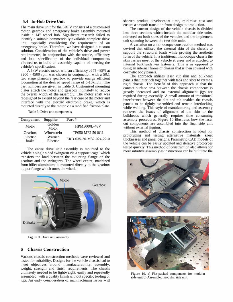
5.4 In-Hub Drive Unit The main drive unit for the SRFV consists of a customised motor, gearbox and emergency brake assembly mounted inside a 14” wheel hub. Significant research failed to identify a suitable commercially available complete drive unit, especially considering the requirement of an emergency brake. Therefore, we have designed a custom solution. Consideration of the vehicle’s drive and power requirements, in conjunction with the torque, efficiency and load specification of the individual components allowed us to build an assembly capable of meeting the vehicle’s specification.
A 5kW electric motor with an efficiency of 75 - 85% at 3200 - 4500 rpm was chosen in conjunction with a 50:1 two stage planetary gearbox to provide energy efficient locomotion at the desired speed range of 5-10km/hr. The part numbers are given in Table 3. Customised mounting plates attach the motor and gearbox intimately to reduce the overall width of the assembly. The motor shaft was redesigned to extend beyond the rear case of the motor and interface with the electric electronic brake, which is mounted directly to the motor via a modified friction plate.
Table 3: Drive unit components
Component Supplier Part #
Motor Golden Motor HPM5000L-48V
Gearbox Wittenstein TP050 MF2 50 0G1 Electric brake
Warner Electric ERD-035-20-M32-024-22-0
The entire drive unit assembly is mounted to the
vehicle’s single sided swingarm via a support ‘cage’ which transfers the load between the mounting flange on the gearbox and the swingarm. The wheel centre, machined from billet aluminium, is mounted directly to the gearbox output flange which turns the wheel.
Figure 9. Drive unit assembly.
6 Chassis Construction Various chassis construction methods were reviewed and tested for suitability. Designs for the vehicle chassis had to meet objectives around manufacturability, assembly, weight, strength and finish requirements. The chassis ultimately needed to be lightweight, easily and repeatedly assembled, with a quality finish without specific tooling or jigs. An early consideration of manufacturing issues will
shorten product development time, minimise cost and ensure a smooth transition from design to production.
The current design of the vehicle chassis is divided into three sections which include the modular side units, mirrored on both sides of the vehicles and the implement unit spanning between the two side units.
A variation on a monocoque construction method was devised that utilised the external skin of the chassis to support the structural loads while proving the aesthetic form of the vehicle. In a traditional monocoque chassis the skin carries most of the vehicle stresses and is attached to internal bulkheads via fasteners. This is as opposed to using an internal frame or chassis that is then covered with cosmetic body panels.
The approach utilises laser cut skin and bulkhead panels that interlock together with tabs and slots to create a rigid chassis. The benefit of this approach is that the contact surface area between the chassis components is greatly increased and no external alignment jigs are required during assembly. A small amount of transitional interference between the slot and tab enabled the chassis panels to be tightly assembled and remain interlocking while welding. This style of manufacturing and assembly removes the issues of alignment of the skin to the bulkheads which generally requires time consuming assembly procedures. Figure 10 illustrates how the laser cut components are assembled into the final side unit without external jigging.
This method of chassis construction is ideal for prototyping and testing alternative materials, sheet thicknesses and panel designs. Parametric CAD models of the vehicle can be easily updated and iterative prototypes tested quickly. This method of construction also allows for more intuitive assembly as instructions can be built into the
Figure 10. a) Flat-packed components for modular side unit b) Assembled modular side unit.
E-Brake
Motor Gearbox
a
b

Proceedings of Australasian Conference on Robotics and Automation, 2-4 Dec 2014, The University of Melbourne, Melbourne, Australia
design by varying the size of tab and slots on different panels. This removes the potential for directional error in assembly. Furthermore, the use of flat, laser cut panels in the design removes the need to create paired parts (left and right handed parts) for the chassis assembly. The same components are able to be used for both sides of the frame as shown in Figure 11.
Using tab and slot features integrated into the chassis components provides part registration and greatly increases the speed and accuracy of assembly. Experiments conducted with various material thicknesses helped determine the effects of variations in the tolerances between tabs and slots on the assembly strength of the construction. This provided results which optimise tolerances and produced a robust, high quality, low cost design.
Figure 11. Full scale prototype chassis for the SRFV during assembly.
7 Conclusion This paper describes the design of a vehicle for a new robotics platform suitable for sustainable agriculture. The vehicle is suitable for traversing between crop rows as the wheel, motor, battery and castor wheel are located in a narrow drive unit. The vehicle allows for a wide range of farm operations including weeding, plating, fertilising, and harvesting due to the modular centre section that spans between the drive units. Due to its low mass spread across four wheels the vehicle will have a low disturbance impact on the field.
The vehicle is in the final stages of assembly. The next stage is to rigorously test the vehicle’s performance under a wide variety of operating conditions. In parallel, we are developing a suitable sensing and navigation system for autonomous operation.
Acknowledgements This work was supported in part by the Queensland Department of Agriculture, Fisheries and Forestry grant “Strategic Investment in Farm Robotics.”
References [Apostolopoulos, 2001] D. Apostolopoulos. Analytic
configuration of wheeled robotic locomotion, 2001. [Åstrand and Baerveldt, 2002] B. Åstrand, and A.
Baerveldt. An agricultural mobile robot with vision-based perception for mechanical weed control.
Autonomous Robots 13(1): 21-35, 2002. [Bakker et al., 2009] T. Bakker, L.V. Asselt, Bontsema,
J. J. Muller, and Straten G.V. Systematic design of autonomous platform for robotic weeding. Journal of Terramechanics, 2009.
[Beckie and Tardif, 2012] H.J. Beckie, and F.J. Tardif. Herbicide cross resistance in weeds. Crop Protection 35(0): 15-28, 2012.
[Bekker, 1956] M. G. Bekker. Theory of land locomotion: The mechanics of vehicle mobility, University of Michigan Press, 1956.
[Bekker, 1960] M. G. Bekker. Off-the-road locomotion: Research and development in terramechanics, University of Michigan Press Ann Arbor, 1960.
[Carvill, 1994] James Carvill. Mechanical engineer's data handbook, Butterworth-Heinemann, 1994.
[Clearpath Robotics, 2013] Clearpath Robotics. Grizzly, 2013.
[Day, 2010] W. Day. Engineering advances for input reduction and systems management to meet the challenges of global food and farming futures. Journal of Agricultural Science(149): 55-61, 2010.
[GRDC, 2010] GRDC. Adoption of no-till cropping practices in australian grain growing regions, 2010.
[Harvest Automation, 2014] Harvest Automation. Hv-100, 2014.
[Hobbs, 2007] P.R. Hobbs. Conservation agriculture: What is it and why is it important for future sustainable food production? Journal of Agricultural Science - Cambridge 145(2): 127, 2007.
[Jazar, 2008] Reza N Jazar. Vehicle dynamics: Theory and application, Springer, 2008.
[Jensen et al., 2012] K. Jensen, SH. Nielsen, RN. Joergensen, A. Boegild, NJ. Jacobsen, OJ. Joergensen, and CL. Jaeger-Hansen. A low cost, modular robotics tool carrier for precision agriculture research. Proceedings 11th International Conference on Precision Agriculture Indianapolis, USA, 2012.
[Karaftath, 1988] L. Karaftath. Rolling resistance of off‐road vehicles. Journal of Construction Engineering and Management 114(3): 458-471, 1988.
[Kassler, 2001] M. Kassler. Agricultural automation in the new millennium. Computers and Electronics in Agriculture 30(1–3): 237-240, 2001.
[Kongskilde Industries A/S, 2013] Kongskilde Industries A/S. Kongskilde vibro crop robotti, 2013.
[Madsen and Jakobsen, 2001] T. E. Madsen, and H. L. Jakobsen. Mobile robot for weeding. Department of Control and Engineering design - Technical University of Denmark, 2001.
[National Farmers Federation, 2013] National Farmers Federation. The blueprint for australian agriculture | 2013-2020 2013.
[Preston, 2013] C. Preston. What has herbicide resistance taught us? GRDC - Global Herbicide Resistance Challenge. Perth, 2013.
[Raper, 2005] R.L. Raper. Agricultural traffic impacts on soil. Journal of Terramechanics 42(3–4): 259-280, 2005.
[Ruckelshausen et al., 2009] A. Ruckelshausen, P.

Proceedings of Australasian Conference on Robotics and Automation, 2-4 Dec 2014, The University of Melbourne, Melbourne, Australia
Biber, M. Dorna, H. Gremmes, R. Klose, A. Linz, F. Rahe, R. Resch, M. Thiel, and D. Trautz. Bonirob–an autonomous field robot platform for individual plant phenotyping. Precision agriculture 9: 841, 2009.
[Sinden et al., 2004] J. Sinden, R. Jones, S. Hester, D. Odom, C. Kalisch, R. James, O. Cacho, and G. Griffith. The economic impact of weeds in australia.
Technical Series 8, 2004. [Smart, 2013] Weed Smart. 2013. [Wong, 2001] J. Y. Wong. Theory of ground vehicles,
Wiley. com, 2001. [Wong, 2009] J. Y. Wong. Terramechanics and off-road
vehicle engineering: Terrain behaviour, off-road vehicle performance and design, Butterworth-Heinemann, 2009.