a lift simulation prototype v c galpin & s t rockhomepages.inf.ed.ac.uk/vgalpin1/ps/gr95.pdf ·...
TRANSCRIPT
A LIFT SIMULATION
A LIFT SIMULATION PROTOTYPE
V C Galpin & S T Rock
Computer Science Department
University of the Witwatersrand, Johannesburg
Wits
2050 South Africa
A LIFT SIMULATION 1
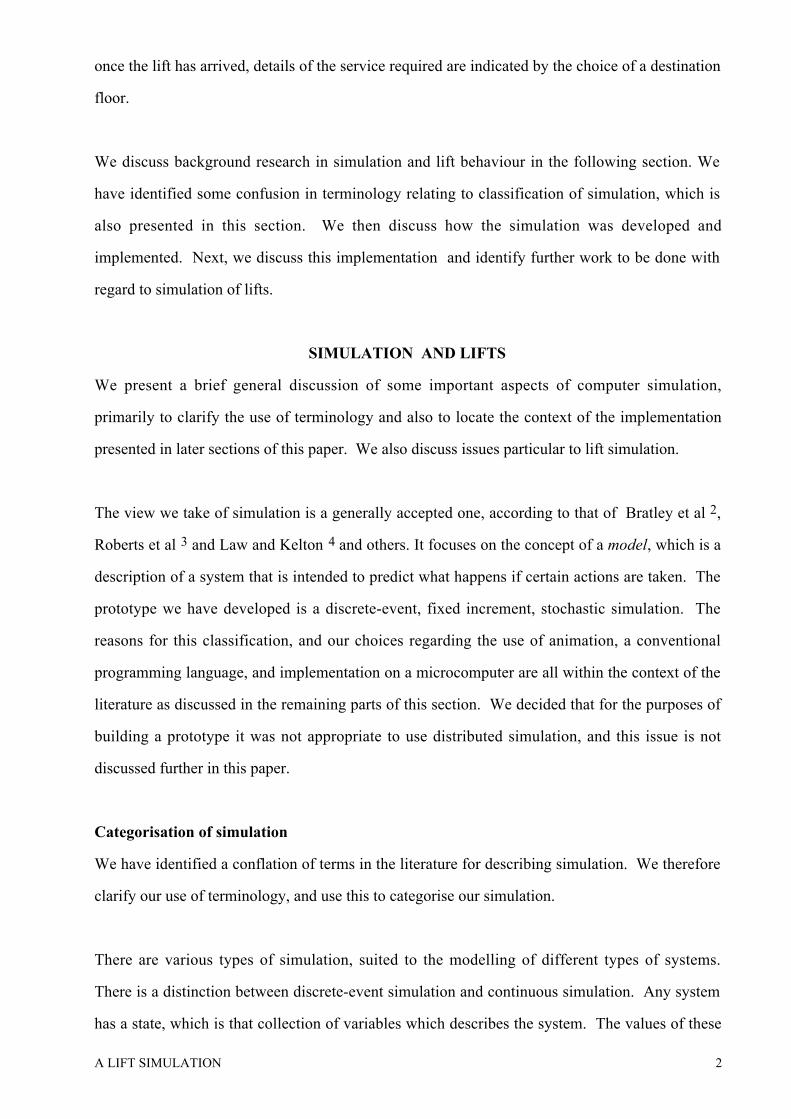
SUMMARY
We present a simple simulation of lift (or elevator) operation that has been developed as a
prototype to address the need for the development of such systems. We first define the type of
simulation that has been developed as a discrete-event, dynamic, stochastic simulation. To do
this, we present an overview of pertinent research in computer simulation, and identify some
ambiguity in the use of terminology. We then describe the system that we have developed. Next
we discuss the decisions taken in its realisation, which are related to our research overview, and
end by identifying some areas that we feel warrant further development. We believe that such a
simulation can provide an important tool for the designers of lift systems. This prototype
demonstrates its feasibility.
Keywords : Simulation, model, lift, objective function, discrete-event.
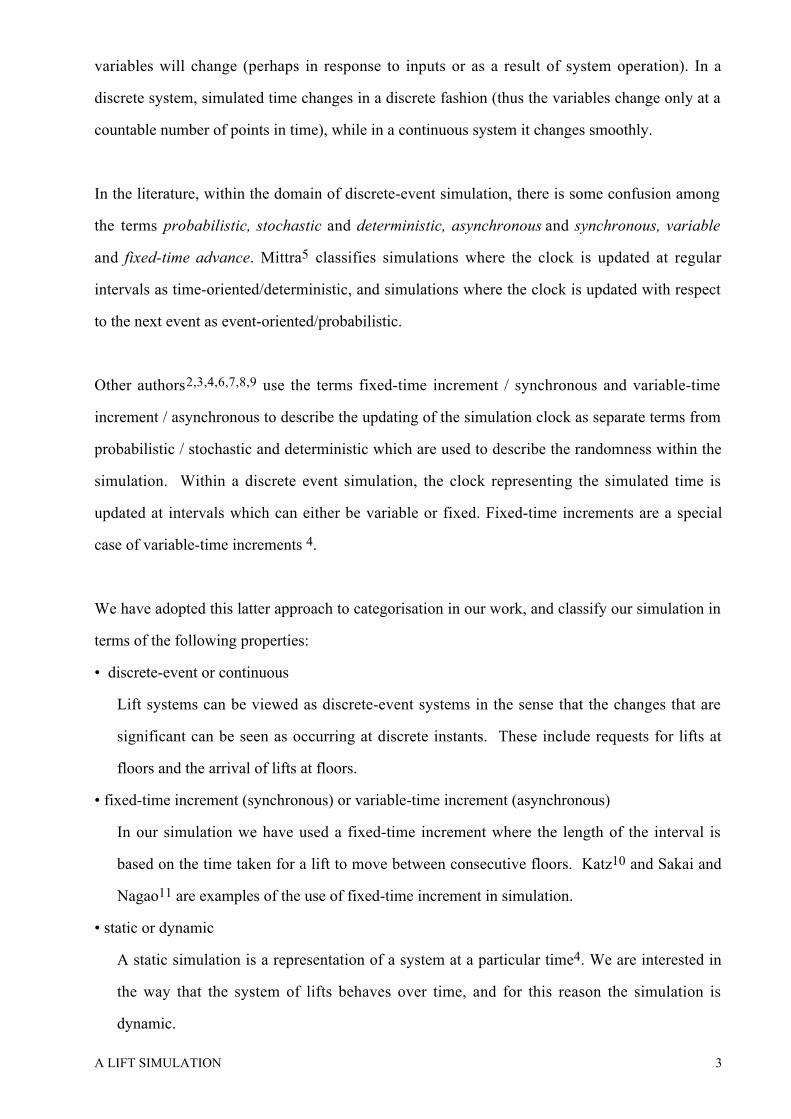
INTRODUCTION
A bank of lifts is a physical system whose behaviour can greatly affect the day-to-day lives of
many individuals. If it is possible to model this behaviour, the provision of a simulation that can
be used to examine the effects of different scheduling policies becomes feasible. This paper
describes a prototype that was developed to demonstrate that such a simulation can be created.
While it is not physically possible, at least at the present time, to have a lift system that provides
service the instant it is requested to every user, it is certainly possible to avoid the situation where
lifts make many unnecessary trips. In other words, what we wish to achieve is a situation that
�“pleases most of the people most of the time�”. This relates directly to the objective function we
have found in Ladany & Hersh1 (presented in Traffic Generation and Statistics) which forms the
basis of the model that we have constructed. The ultimate goal is to have a tool whereby it can
be determined what sorts of lift behaviour, for any given configuration of lifts in a building, will
achieve the desired situation. This is done by choosing a lift scheduling system and testing it
over a period of time to obtain values for the objective function.
What we describe in this paper is an attempt to provide a system that will simulate a
(configurable) lift bank that services requests from users. Described simplistically, the requests
are made by generating a signal (pushing a button) at the floor at which the lift is required, and
A LIFT SIMULATION 2
once the lift has arrived, details of the service required are indicated by the choice of a destination
floor.
We discuss background research in simulation and lift behaviour in the following section. We
have identified some confusion in terminology relating to classification of simulation, which is
also presented in this section. We then discuss how the simulation was developed and
implemented. Next, we discuss this implementation and identify further work to be done with
regard to simulation of lifts.
SIMULATION AND LIFTS
We present a brief general discussion of some important aspects of computer simulation,
primarily to clarify the use of terminology and also to locate the context of the implementation
presented in later sections of this paper. We also discuss issues particular to lift simulation.
The view we take of simulation is a generally accepted one, according to that of Bratley et al 2,
Roberts et al 3 and Law and Kelton 4 and others. It focuses on the concept of a model, which is a
description of a system that is intended to predict what happens if certain actions are taken. The
prototype we have developed is a discrete-event, fixed increment, stochastic simulation. The
reasons for this classification, and our choices regarding the use of animation, a conventional
programming language, and implementation on a microcomputer are all within the context of the
literature as discussed in the remaining parts of this section. We decided that for the purposes of
building a prototype it was not appropriate to use distributed simulation, and this issue is not
discussed further in this paper.
Categorisation of simulation
We have identified a conflation of terms in the literature for describing simulation. We therefore
clarify our use of terminology, and use this to categorise our simulation.
There are various types of simulation, suited to the modelling of different types of systems.
There is a distinction between discrete-event simulation and continuous simulation. Any system
has a state, which is that collection of variables which describes the system. The values of these
A LIFT SIMULATION 3
variables will change (perhaps in response to inputs or as a result of system operation). In a
discrete system, simulated time changes in a discrete fashion (thus the variables change only at a
countable number of points in time), while in a continuous system it changes smoothly.
In the literature, within the domain of discrete-event simulation, there is some confusion among
the terms probabilistic, stochastic and deterministic, asynchronous and synchronous, variable
and fixed-time advance. Mittra5 classifies simulations where the clock is updated at regular
intervals as time-oriented/deterministic, and simulations where the clock is updated with respect
to the next event as event-oriented/probabilistic.
Other authors2,3,4,6,7,8,9 use the terms fixed-time increment / synchronous and variable-time
increment / asynchronous to describe the updating of the simulation clock as separate terms from
probabilistic / stochastic and deterministic which are used to describe the randomness within the
simulation. Within a discrete event simulation, the clock representing the simulated time is
updated at intervals which can either be variable or fixed. Fixed-time increments are a special
case of variable-time increments 4.
We have adopted this latter approach to categorisation in our work, and classify our simulation in
terms of the following properties:
�• discrete-event or continuous
Lift systems can be viewed as discrete-event systems in the sense that the changes that are
significant can be seen as occurring at discrete instants. These include requests for lifts at
floors and the arrival of lifts at floors.
�• fixed-time increment (synchronous) or variable-time increment (asynchronous)
In our simulation we have used a fixed-time increment where the length of the interval is
based on the time taken for a lift to move between consecutive floors. Katz10 and Sakai and
Nagao11 are examples of the use of fixed-time increment in simulation.
�• static or dynamic
A static simulation is a representation of a system at a particular time4. We are interested in
the way that the system of lifts behaves over time, and for this reason the simulation is
dynamic.

A LIFT SIMULATION 4
�• stochastic (probabilistic) or deterministic.
The system is a stochastic simulation since there is a random component in the system, which
is the behaviour of lift users. (The behaviour of the lifts is deterministic, depending only on
requests for service and scheduling policies. However, the model is driven by random input,
in the form of the distribution of lift users. Thus we see the model as being deterministic, but
the simulation itself as being stochastic, where we are interested in the use of lifts rather than
the lifts themselves.)
What we describe in the remainder of this paper is a discrete-event, fixed-time increment,
dynamic, stochastic simulation of a bank of lifts. It was developed on a microcomputer in
Pascal, under DOS, and provides animation on a conventional text screen. Its primary value is
that it is a prototype for the development of future lift operation simulations, and we see a real
need for such systems to be built.
Use of simulation in lift operation design
The implementation we have done has been based to a large extent on the use of simulation
described by Ladany & Hersh 1. Their approach is to view the problem of lift design as being a
complex one. It is difficult to solve with analytic methods such as queueing theory and therefore
simulation is proposed as an alternative method. Their paper discusses the objective of the system
in depth, and presents a function that is to be minimised to improve the operation of the lift
system. We have used this objective function in our implementation. The paper also provides a
good discussion of lift operating policies, and we have used their categorisation of external calls
and their search policies. The actual realisation of the simulation is not discussed by them,
though the general operation of the simulation is described by a flow chart.
Adler 12 gives some general guidelines regarding computer simulation of lifts. These are given
in the context of a general discussion of lifts as transportation systems, and include the interaction
of various components of lift systems (such as mechanical, electrical, operation, installation).
Adler also stresses the value of such simulations.
A LIFT SIMULATION 5
Knuth 13 describes a lift simulation, in order to illustrate the appropriate use of doubly linked lists
as a data structure. This approach concentrates on the data structures, rather than on the
simulation or the lift operation, and describes a fixed system of 1 lift that services 5 floors.
Moeck & McDermid14 describe the use of formal specification (Milner�’s CCS15) for
implementing a lift control system. This uses CCS to specify a particular operation of a lift
system, while avoiding the details of scheduling. The system is seen as a method of switching
off lights that have been switched on by an external agent (much in the way we see servicing
requests from lift users). They focus on the use of communicating agents for achieving their
logic, and see the lift model primarily as a good example to illustrate the use of formal
specification as an aid to software implementation.
Expert system technology has been useful in the design of lift systems from the point of view of
their mechanical and electrical operation16. We are also aware of various lift manufacture
companies using CAD systems in the design of lifts and overall lift systems in this context.
However we have not found any use of computer technology or simulation in the design of lift
systems with respect to their operation and scheduling policies. Lifts that use feedback from the
current status of the lift system to change their own behaviour (by providing input to the
scheduling controller) were not considered as these are very expensive to implement.
Implementation issues in simulation
In developing our simulation prototype, various decisions were made based on supporting
literature. These are discussed briefly here.
It was decided to develop the prototype in a conventional programming language (Pascal) rather
than using a simulation language 2,4,5,17,18. We felt that there were no significant advantages
attached to the use of a simulation language, and that if we did use one, encoding the search
policies would be made more difficult. We also felt that the provision of animation for the
simulation was important 19. The use of animation gives improved confidence in the simulation
and allows the user to ensure that the rules for the system have been implemented
correctly20,21,22. This is not to suggest that animation can be used to force the acceptance of
A LIFT SIMULATION 6
faulty logic in a design. Bell & O'Keefe21 suggest that when using animation in a simulation the
visual part of the display can be developed first and then the logic to drive this display can be
developed. This allows the logic to be checked, and enhances the chances of identifying
inconsistencies. Bell & O'Keefe21 warn, however, that the animation is only part of the
simulation - statistical information gathering and analysis is still necessary. We chose to use a
microcomputer for implementation 19,20.
The three decisions described above also affected each other, and though they were made in the
context of prototype development, we feel that this does not diminish their appropriateness.
PROTOTYPE IMPLEMENTATION
This section describes how the lift simulation prototype was implemented. First we describe what
the program does and how the operating policies of the lift system were implemented. Next we
discuss the major data structures and procedures that were developed. The code fragments used
for explanation are in Pascal, taken from the actual implementation and simplified in places to
make them more readily understandable. We also describe the core of the program in this
manner. We then discuss traffic generation which includes a description of the objective
function. In the next section, Analysis, we present an evaluation of the decisions taken during
implementation of the prototype with regard to some of the issues in simulation.
General operation
The program is a simulation of a bank of lifts containing a number of variables that the user can
specify. The user can choose the number of lifts, the number of floors and the volume or capacity
of each individual lift. The system is executed under an operating policy which consists of a
search policy and a routing policy. Search policies decide which floor the lift should go to if it is
empty and routing polices decide which floors each lift can service. A floor is said to be blocked
for a particular lift if the lift cannot serve it.
The user is required to specify the arrivals of traffic to a floor and the departures of traffic from a
lift at a floor, as percentages of the arrivals and departures to all floors. This defines the traffic
pattern of the lift system, and the accuracy with which this is done will directly affect the validity

A LIFT SIMULATION 7
of the simulation run. There are two types of simulation run - a statistical run with no animated
display but where a report can be printed, and a graphics run with an animated display but with
no report facilities.
The simulation uses a fixed-time increment4,6,7,8,9. The basic time-unit of a simulation run is the
time taken for a lift to travel between two consecutive floors. (We have assumed that this is the
same for both upwards and downwards travel, and that there is no difference in time taken
whether the lift stops or not.) All other variables concerning time are defined in terms of this
basic time-unit. They are the number of arrivals per time-unit and the length of an individual run
in time-units. The user can specify the number of individual runs to be done with the same
variables. Table 1 shows the ranges and values that the user-selectable variables can take.
The facility to allow a number of runs to be done, was implemented to allow for repeated runs to
be done under transient conditions i.e before steady state has been reached6. The statistics are
calculated across each run, and averages and variances are calculated1,7. This ameliorates the
fluctuations that can occur in the transient period.
The phrase 'simulation run' will be used to describe executing the simulation with a specific set of
variables and consists of a set of 'individual runs' which each consist of an execution of the
simulation for a specified time length. The objective function is calculated for each individual
run and then averaged to get a value for the simulation run. The simulation then executes as a
loop; the lifts move depending upon the conditions and the policies, and new events are generated
- more people are put into the system - depending on the traffic specifications and the arrivals per
time-unit. When the simulation run ends or the user presses 'esc' to terminate the simulation run,
the user can either quit, execute the simulation with the same variables or enter new variables and
start a new simulation run.
Operation policies
There is one main procedure to implement the decisions made by the search policy being used -
�‘findcall�’. (Routing policies are implemented in the data structure for the lifts. Each lift has an
array of floors that it can and cannot serve.) �‘Findcall�’ is called if the lift is in a wait state. There
A LIFT SIMULATION 8
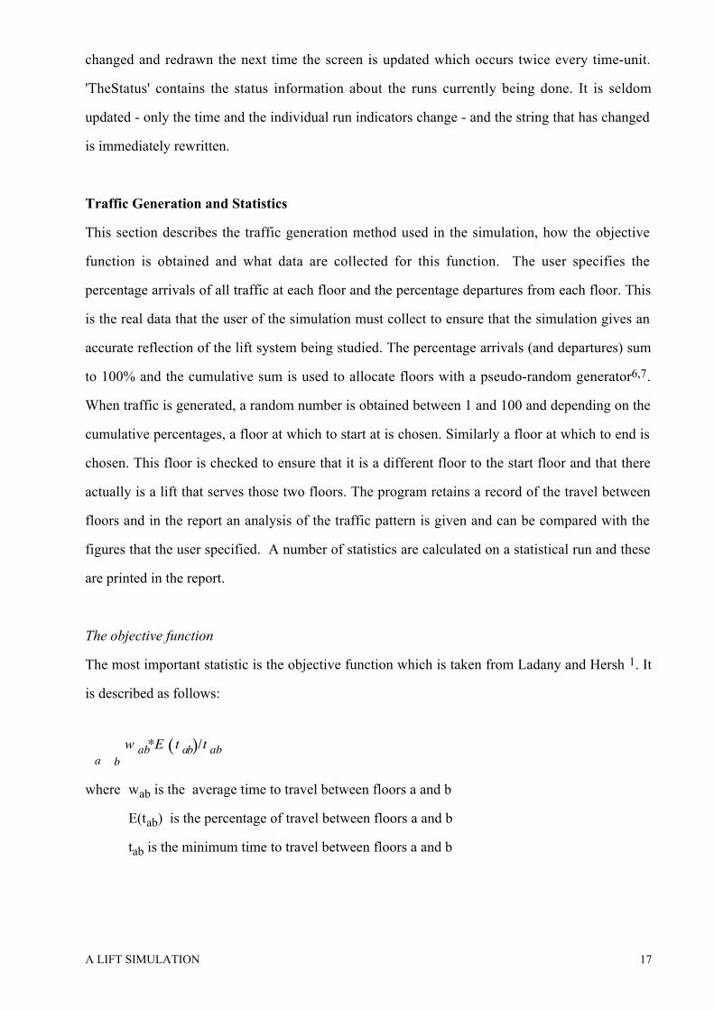
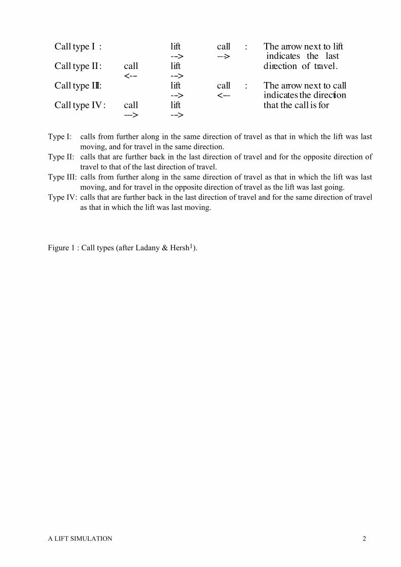
are various types of call (taken from Ladany and Hersh1 ) which are discussed here. Call types
and their categorisation are described in Figure 1.
Type I calls are from floors further along in the same direction of travel as that in which the lift
was last moving, and for travel in the same direction. Type II calls are from floors further back
in the last direction of travel and for the opposite direction of travel to that of the last direction of
travel. Type III calls are from floors further along in the same direction of travel as that in which
the lift was last moving, for travel in the opposite direction of travel and Type IV calls are from
further back in the last direction of travel and for the same direction of travel as that in which the
lift was last moving.
Type I calls are looked for first, then type II calls. If there are neither of these, then there are two
options: forward search and backward search. In forward search, the lift will go to the nearest
floor with a type III call, if none exist then the lift will go to the farthest floor with a type IV call.
In backward search the opposite occurs.
The procedure 'findcall' implements this. It looks for type I calls first, type II calls next and then
type III, then type IV if doing forward search; or for type IV and then type III if doing backward
search. There are four procedures, 'Call_I', 'Call_II', 'Call_III' and Call_IV' which check to see
which call is currently occurring. In both type III and IV calls, no collection of passengers while
travelling to the call floor is allowed as the lift will change its direction when it gets to the called
floor and passengers that are picked up could be going further than the call floor. Obviously a lift
cannot serve a floor for which it is blocked. When a call is discovered, its type is not recorded,
but the direction that the lift will take to service the call and the direction the lift will take after
having picked up passengers, are stored within the data structure for that lift, as described in the
next section.
Major data structures
The data structures described here play an important role in the program as they encapsulate the
data of the lift system. The two major data structures are the array of lifts and the array of floors.
The move array is used to simplify operations on lift behaviour. All constants beginning with
A LIFT SIMULATION 9
'max' refer to constants that set the maximum parameters of the implementation. (The convention
we use for comments is to indent comments that apply to more than one line of code; these will
be spread over the lines to which they are relevant.)
The lift array
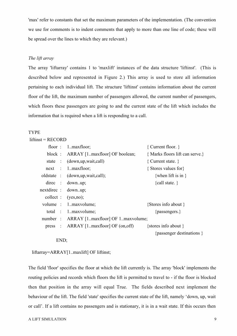
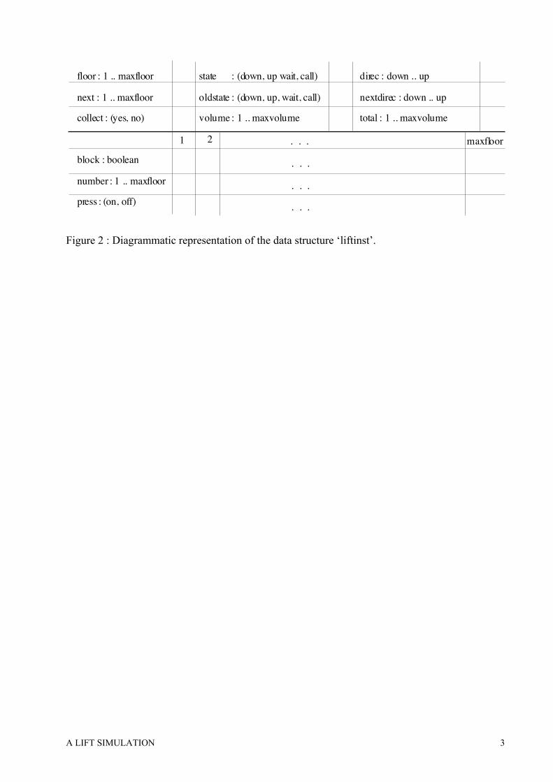
The array 'liftarray' contains 1 to 'maxlift' instances of the data structure 'liftinst'. (This is
described below and represented in Figure 2.) This array is used to store all information
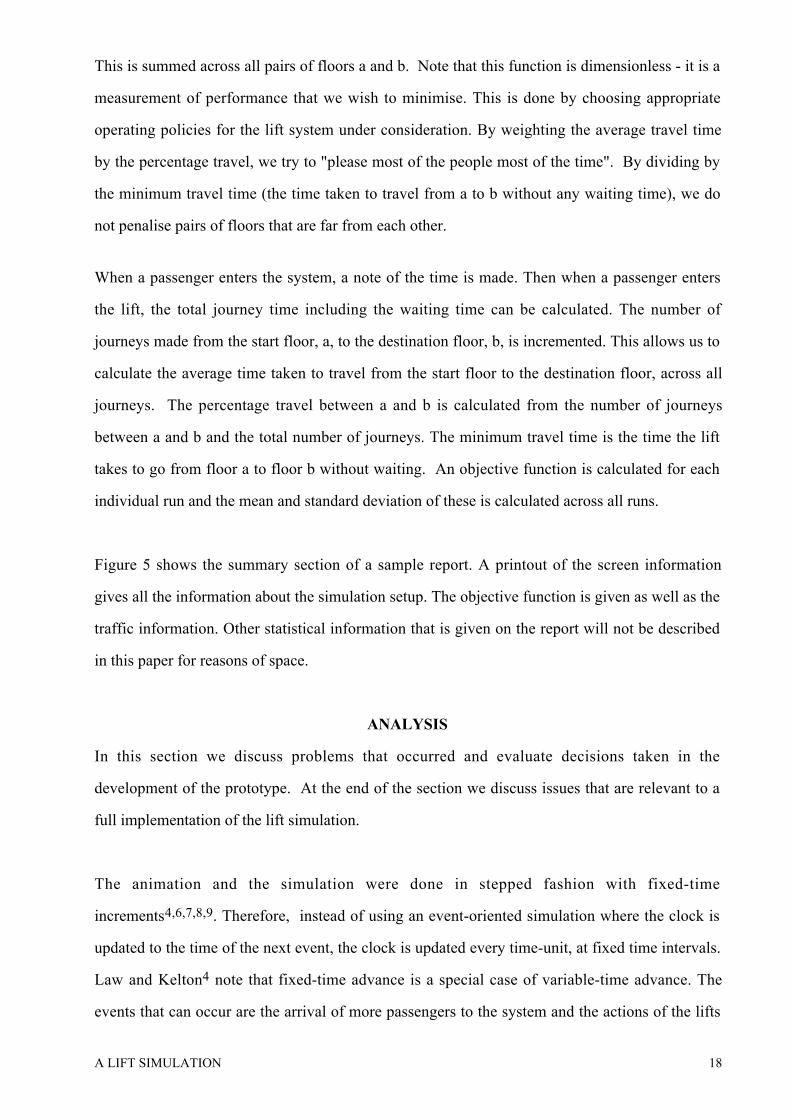
pertaining to each individual lift. The structure 'liftinst' contains information about the current
floor of the lift, the maximum number of passengers allowed, the current number of passengers,
which floors these passengers are going to and the current state of the lift which includes the
information that is required when a lift is responding to a call.
TYPE
liftinst = RECORD
floor : 1..maxfloor; { Current floor. }
block : ARRAY [1..maxfloor] OF boolean; { Marks floors lift can serve.}
state : (down,up,wait,call) { Current state. }
next : 1..maxfloor; { Stores values for}
oldstate : (down,up,wait,call); {when lift is in }
direc : down..up; {call state. }
nextdirec : down..up;
collect : (yes,no);
volume : 1..maxvolume; {Stores info about }
total : 1..maxvolume; {passengers.}
number : ARRAY [1..maxfloor] OF 1..maxvolume;
press : ARRAY [1..maxfloor] OF (on,off) {stores info about }
{passenger destinations }
END;
liftarray=ARRAY[1..maxlift] OF liftinst;
The field 'floor' specifies the floor at which the lift currently is. The array 'block' implements the
routing policies and records which floors the lift is permitted to travel to - if the floor is blocked
then that position in the array will equal True. The fields described next implement the
behaviour of the lift. The field 'state' specifies the current state of the lift, namely �‘down, up, wait
or call�’. If a lift contains no passengers and is stationary, it is in a wait state. If this occurs then
A LIFT SIMULATION 10
the field 'oldstate' contains the previous direction of travel, and this is used by the search policy in
deciding which call to service. When a lift is in wait state 'findcall' is called to see if a floor needs
servicing - if one is found the lift changes to state �‘call�’. The field 'direc' stores the direction in
which the lift must move to service the call, and 'nextdirec' stores the direction in which it must
move after it has serviced the call. 'Next' stores the floor of the call that is being serviced.
'Collect' specifies whether a lift that is in call state can collect passengers on its way to the floor
of the call to be serviced. The field 'volume' records the capacity of the lift as specified by the
user. 'Total' specifies the current number of passengers in the lift. The arrays 'number' and 'press'
record information relating to where the passengers are going. 'Number' records how many are
going to each floor and 'press' records whether the button to a particular floor is on or off. This
second array is only used to make the code clearer.
The floor array
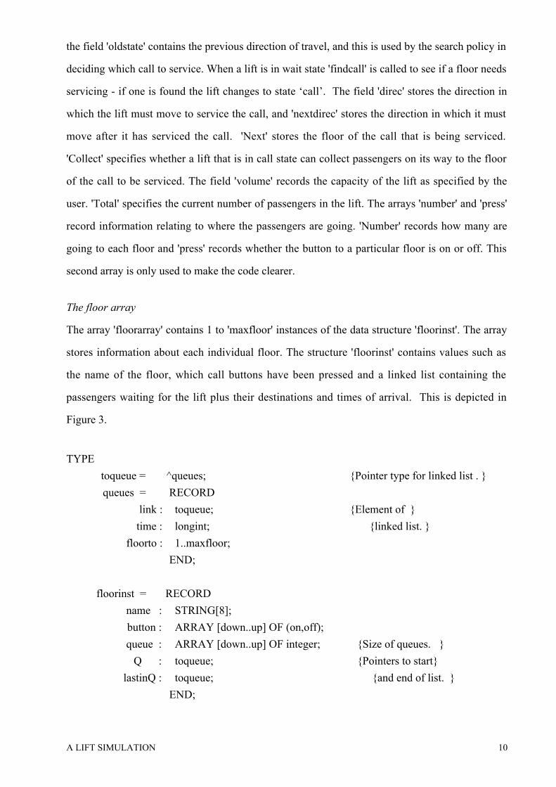
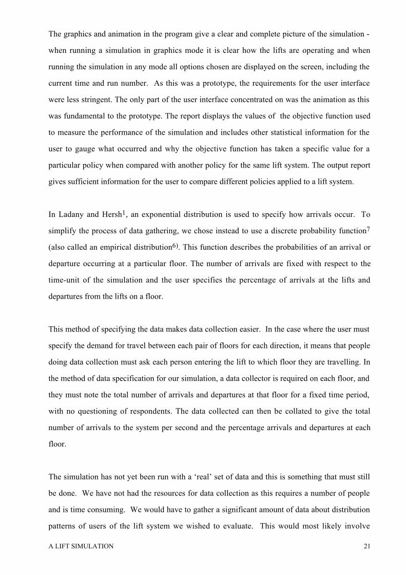
The array 'floorarray' contains 1 to 'maxfloor' instances of the data structure 'floorinst'. The array
stores information about each individual floor. The structure 'floorinst' contains values such as
the name of the floor, which call buttons have been pressed and a linked list containing the
passengers waiting for the lift plus their destinations and times of arrival. This is depicted in
Figure 3.
TYPE
toqueue = ^queues; {Pointer type for linked list . }
queues = RECORD
link : toqueue; {Element of }
time : longint; {linked list. }
floorto : 1..maxfloor;
END;
floorinst = RECORD
name : STRING[8];
button : ARRAY [down..up] OF (on,off);
queue : ARRAY [down..up] OF integer; {Size of queues. }
Q : toqueue; {Pointers to start}
lastinQ : toqueue; {and end of list. }
END;
A LIFT SIMULATION 11
floorarray = ARRAY[1..maxfloor] OF floorinst;
The field 'name' contains the label for the floor as the user may wish to name floors. The arrays
'queue' and 'button' record information about the up and down queues. 'Queue' records the
number in each queue and 'button' records which buttons have been pressed. The variable 'button'
is redundant but is used to make the code clearer. A floor has a list of people waiting for the lift.
'Q' and 'lastinQ' point to the first item and the last item of this list respectively. All people are put
on one queue regardless of which direction they are going in. The list is implemented as a FIFO
list. This describes the behaviour of people waiting for a lift. The fields in the 'queues' structure
are 'link' which is a pointer to the next record in the list, 'time' which stores the time that this
passenger was generated - the time that it was put in the queue - and 'floorto' stores the floor to
which the passenger is going.
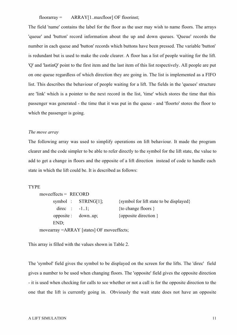
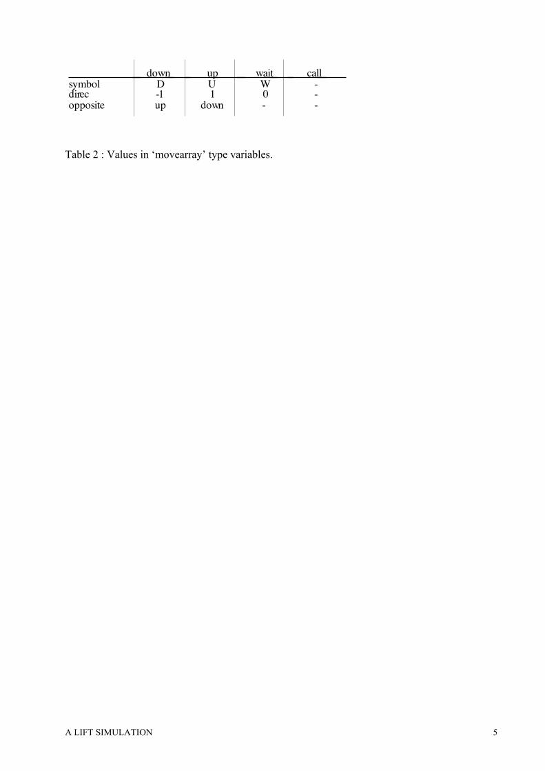
The move array
The following array was used to simplify operations on lift behaviour. It made the program
clearer and the code simpler to be able to refer directly to the symbol for the lift state, the value to
add to get a change in floors and the opposite of a lift direction instead of code to handle each
state in which the lift could be. It is described as follows:
TYPE
moveeffects = RECORD
symbol : STRING[1]; {symbol for lift state to be displayed}
direc : -1..1; {to change floors }
opposite : down..up; {opposite direction }
END;
movearray =ARRAY [states] OF moveeffects;
This array is filled with the values shown in Table 2.
The 'symbol' field gives the symbol to be displayed on the screen for the lifts. The 'direc' field
gives a number to be used when changing floors. The 'opposite' field gives the opposite direction
- it is used when checking for calls to see whether or not a call is for the opposite direction to the
one that the lift is currently going in. Obviously the wait state does not have an opposite
A LIFT SIMULATION 12
direction. The call state has no values associated with it because when a lift is in call state, it
could be travelling in either direction.
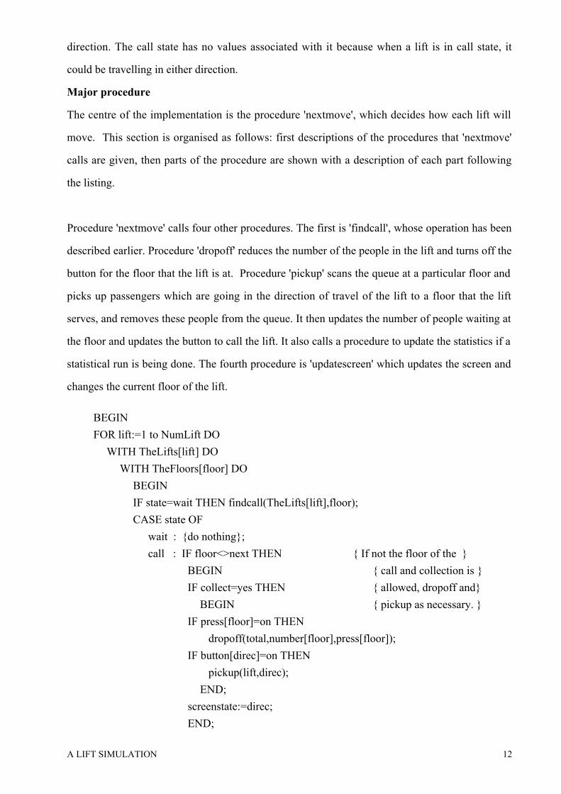
Major procedure
The centre of the implementation is the procedure 'nextmove', which decides how each lift will
move. This section is organised as follows: first descriptions of the procedures that 'nextmove'
calls are given, then parts of the procedure are shown with a description of each part following
the listing.
Procedure 'nextmove' calls four other procedures. The first is 'findcall', whose operation has been
described earlier. Procedure 'dropoff' reduces the number of the people in the lift and turns off the
button for the floor that the lift is at. Procedure 'pickup' scans the queue at a particular floor and
picks up passengers which are going in the direction of travel of the lift to a floor that the lift
serves, and removes these people from the queue. It then updates the number of people waiting at
the floor and updates the button to call the lift. It also calls a procedure to update the statistics if a
statistical run is being done. The fourth procedure is 'updatescreen' which updates the screen and
changes the current floor of the lift.
BEGIN
FOR lift:=1 to NumLift DO
WITH TheLifts[lift] DO
WITH TheFloors[floor] DO
BEGIN
IF state=wait THEN findcall(TheLifts[lift],floor);
CASE state OF
wait : {do nothing};
call : IF floor<>next THEN { If not the floor of the }
BEGIN { call and collection is }
IF collect=yes THEN { allowed, dropoff and}
BEGIN { pickup as necessary. }
IF press[floor]=on THEN
dropoff(total,number[floor],press[floor]);
IF button[direc]=on THEN
pickup(lift,direc);
END;
screenstate:=direc;
END;

A LIFT SIMULATION 13
....... (continued after next paragraph)
For each lift and for the floor that it is currently at, the loop in the above code fragment is
executed. If the lift is in a wait state then 'findcall' is called to see if there is a call. If after this, the
lift is still in a wait state, then nothing happens. If the lift is in call state, i.e. it is on its way to the
floor of the call, then if the floor is not the floor it is going to and collections are allowed,
procedure 'dropoff' is called if there are passengers to get off at this floor. If there are people
waiting to go in the direction in which the lift is travelling, procedure 'pickup' is called. It also
calls a procedure to update the statistics if a statistical run is being done.
....... (continued from before preceding paragraph)
ELSE { If at floor of call}
BEGIN {i.e. floor = next }
IF press[floor]=on THEN {dropoff if necessary. }
dropoff(total,number[floor],press[floor]);
IF button[nextdirec]=on OR total>0 THEN
BEGIN { If people in lift or }
state:=nextdirec; { waiting change to }
pickup(lift,state); { new direction.}
END;
IF total=0 THEN { If nobody got into }
BEGIN { lift, go into wait }
state:=wait; { state & record }
oldstate:=direc; { previous state. }
END;
screenstate:=state;
END;
....... (continued after next paragraph)
In the above code fragment, if the lift is in call state and the lift has arrived at the floor that the
call came from, and if there are any passengers to drop off, 'dropoff' is called. If there are
passengers going in the direction that the lift was called for or there are passengers in the lift,
then the lift changes to its new direction (the direction that it was called for) and 'pickup' is
called. If after this there are actually no people in the lift (no one was picked up) then the lift state

A LIFT SIMULATION 14
changes to wait and the lift's last direction of travel changes to the direction that it would have
changed to, had it picked passengers up.
....... (continued from before preceding paragraph)
up,down : BEGIN
IF press[floor]=on THEN { Dropoff if necessary. }
dropoff(total,number[floor],press[floor]);
IF button[state]=on THEN { Pickup if necessary. }
pickup(lift,state);
IF total=0 THEN { If nobody in lift }
BEGIN { change state to wait }
oldstate:=state; { and record previous }
state:=wait; { state. }
END;
screenstate:=state;
END;
END; {case}
updatescreen(floor,lift,total,screenstate);
END;
END;
If the lift is in the state up or down and there are passengers to be dropped off or picked up then
'dropoff' and 'pickup' are called respectively. If there is no one in the lift, then 'oldstate' becomes
equal to the previous direction of travel and the lift is put into wait state. At the end of the loop
�‘updatescreen�’ is called to update the screen and change the current floor of the lift.
The simulation
This section contains a condensed code fragment for the main body of the program which
actually executes the simulation.
REPEAT
inc(TheRun);
initialise;
updaterun(TheRun); { Updates the run number on the screen.}
REPEAT
inc(TheTime);
update(TheTime); { Updates the time on the screen. }
A LIFT SIMULATION 15
nextmove;
redrawscreen;
FOR evnt:=1 TO Arrivals DO makemoreevents;
redrawscreen;
IF keypressed=#27 THEN { #27='esc'}
QuitPressed:=true;
UNTIL TheTime=LengthRun OR QuitPressed;
UNTIL TheRun=NumRun OR QuitPressed;
For each individual run of the simulation, the run number is incremented, the simulation is re-
initialised to the starting point and the run number is updated on the screen. This loop continues
until the full number of individual runs has been completed or the user presses 'esc' to quit the
runs. The inner loop is executed for each time increment. The time is incremented and updated on
the screen. The procedure 'nextmove' is called to determine what the lifts should do and the
screen is then redrawn by �‘redrawscreen�’ if the run is a graphics run. More events (i.e people
waiting for lifts) are created according to the number of events per time-unit and the screen is
redrawn again. It then checks whether the user has pressed 'esc' and sets 'QuitPressed' equal to
true if this has occurred. This inner loop continues until the time is equal to the length of an
individual run, or the user presses 'esc'.
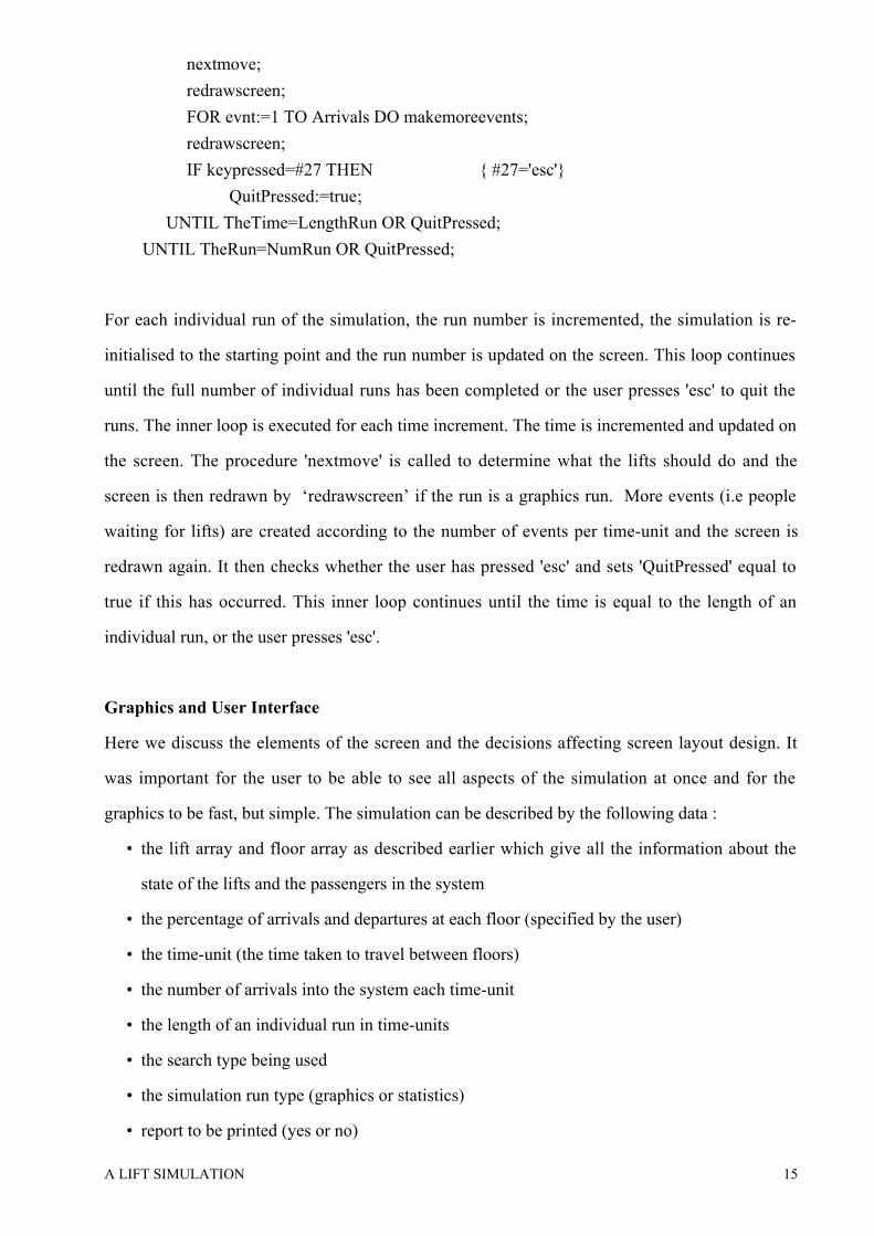
Graphics and User Interface
Here we discuss the elements of the screen and the decisions affecting screen layout design. It
was important for the user to be able to see all aspects of the simulation at once and for the
graphics to be fast, but simple. The simulation can be described by the following data :
�• the lift array and floor array as described earlier which give all the information about the
state of the lifts and the passengers in the system
�• the percentage of arrivals and departures at each floor (specified by the user)
�• the time-unit (the time taken to travel between floors)
�• the number of arrivals into the system each time-unit
�• the length of an individual run in time-units
�• the search type being used
�• the simulation run type (graphics or statistics)
�• report to be printed (yes or no)
A LIFT SIMULATION 16
�• the current time in time-units, the number of individual runs and the current run number.
The statistics are not displayed on the screen as they are gathered, first because there is not
enough room and we felt the other information was more important, and secondly because the
major statistic - the objective function - is only calculated at the end of all individual runs.
An example of the screen is given in Figure 4. The left hand side of the screen contains a display
of the lift system. It shows the number of lifts and number of floors specified by the user with
the floor labels given by the user. If the user is doing an animated simulation run, the lifts move.
Each lift has a number representing the number of passengers and a symbol representing what
state the lift is in. The maximum volume of each lift is shown at the top of the lift shaft. Each
floor has two queues - an up queue and a down queue - which are represented on the screen by
two numbers giving the size of the queue. A blocked floor for a particular lift is indicated by a
broken line in the column next to the column in which the lift moves. Next to the lift display, the
percentage arrivals and departures specified by the user is given for each floor. On the right hand
side of the screen the status information is displayed. The time-unit in seconds, the number of
arrivals per time-unit, the length of an individual run, the search type, the simulation run type and
whether a report is to be printed, are shown. At the bottom of the screen, two indicators - time
and run - give the time elapsed (in seconds) and the individual run number.
This display encapsulates everything about the simulation except the statistics gathering. The
rest of the user interface is very simple. The user can specify the variables for a simulation run,
and start and interrupt a simulation run. The variables the user can specify are those in Table 1.
The aim of the system was to provide fast, simple graphical, animated display. All elements of
the screen are text characters - there are no true graphics in the Turbo Pascal sense. Direct
memory access was enabled for 'write' and 'writeln' statements. This, together with 'gotoxy,
enables fast positioning of strings on the screen. The simulation runs so fast that delays are
necessary for the animation to be seen clearly. There are two screen arrays - 'TheScreen' and
'TheStatus'. They are integer arrays of strings. 'TheScreen' array stores the lift system and
whenever a string is changed, for example, when a queue increases in size, the string is marked as
A LIFT SIMULATION 17
changed and redrawn the next time the screen is updated which occurs twice every time-unit.
'TheStatus' contains the status information about the runs currently being done. It is seldom
updated - only the time and the individual run indicators change - and the string that has changed
is immediately rewritten.
Traffic Generation and Statistics
This section describes the traffic generation method used in the simulation, how the objective
function is obtained and what data are collected for this function. The user specifies the
percentage arrivals of all traffic at each floor and the percentage departures from each floor. This
is the real data that the user of the simulation must collect to ensure that the simulation gives an
accurate reflection of the lift system being studied. The percentage arrivals (and departures) sum
to 100% and the cumulative sum is used to allocate floors with a pseudo-random generator6,7.
When traffic is generated, a random number is obtained between 1 and 100 and depending on the
cumulative percentages, a floor at which to start at is chosen. Similarly a floor at which to end is
chosen. This floor is checked to ensure that it is a different floor to the start floor and that there
actually is a lift that serves those two floors. The program retains a record of the travel between
floors and in the report an analysis of the traffic pattern is given and can be compared with the
figures that the user specified. A number of statistics are calculated on a statistical run and these
are printed in the report.
The objective function
The most important statistic is the objective function which is taken from Ladany and Hersh 1. It
is described as follows:
w ab* E t ab( ) / t abb
a where wab is the average time to travel between floors a and b
E(tab) is the percentage of travel between floors a and b
tab is the minimum time to travel between floors a and b
A LIFT SIMULATION 18
This is summed across all pairs of floors a and b. Note that this function is dimensionless - it is a
measurement of performance that we wish to minimise. This is done by choosing appropriate
operating policies for the lift system under consideration. By weighting the average travel time
by the percentage travel, we try to "please most of the people most of the time". By dividing by
the minimum travel time (the time taken to travel from a to b without any waiting time), we do
not penalise pairs of floors that are far from each other.
When a passenger enters the system, a note of the time is made. Then when a passenger enters
the lift, the total journey time including the waiting time can be calculated. The number of
journeys made from the start floor, a, to the destination floor, b, is incremented. This allows us to
calculate the average time taken to travel from the start floor to the destination floor, across all
journeys. The percentage travel between a and b is calculated from the number of journeys
between a and b and the total number of journeys. The minimum travel time is the time the lift
takes to go from floor a to floor b without waiting. An objective function is calculated for each
individual run and the mean and standard deviation of these is calculated across all runs.
Figure 5 shows the summary section of a sample report. A printout of the screen information
gives all the information about the simulation setup. The objective function is given as well as the
traffic information. Other statistical information that is given on the report will not be described
in this paper for reasons of space.
ANALYSIS
In this section we discuss problems that occurred and evaluate decisions taken in the
development of the prototype. At the end of the section we discuss issues that are relevant to a
full implementation of the lift simulation.
The animation and the simulation were done in stepped fashion with fixed-time
increments4,6,7,8,9. Therefore, instead of using an event-oriented simulation where the clock is
updated to the time of the next event, the clock is updated every time-unit, at fixed time intervals.
Law and Kelton4 note that fixed-time advance is a special case of variable-time advance. The
events that can occur are the arrival of more passengers to the system and the actions of the lifts

A LIFT SIMULATION 19
which involve loading and unloading of passengers and moving between floors, and the events
are handled at the end of the intervals in which they occur.
There are some disadvantages and advantages to this approach. Law and Kelton4 say that
disadvantages of fixed-time increment advance are that error is introduced by processing events
at the end of the time interval and that one must decide how to order events. The first
disadvantage is a problem in that it can coarsen the simulation if the time interval is not small
enough. It also imposes some assumptions: first that the lifts move between floors all at exactly
the same time instant and secondly that when people arrive at a floor to call a lift, they all arrive
simultaneously. We feel that this approach does make the model slightly coarser than one using
variable time increments. The second disadvantage is less significant as a lift can serve a number
of people simultaneously.
Bratley et al2 list the disadvantages as follows : it is hard to program - although the clock
mechanism is simple there is a problem of deciding how to schedule the non-simultaneous events
at the interval - and the interval often has to be small for reasons of accuracy and this causes the
simulation to be slower. As mentioned above, the fact that events can be treated as simultaneous
because a lift can serve multiple passengers, removes the problem of scheduling events at the
interval. Therefore since the clock mechanism is simple to implement and there is no scheduling
problem, the fixed-time increment approach is easier to implement. The issue of smaller intervals
requiring more computation and therefore causing loss of speed, is not of crucial importance
here, as animation is required. As mentioned in the section Implementation, delays are required
in the program for the animation to run at a speed that allows it to be seen clearly. Many articles
use the speed of simulation as a major criterion to choose between fixed-time advance versus
variable-time advance 8,23,24. However this is less relevant to a simulation with animation.
The fact that the time-unit of the simulation is defined as the time a lift takes to move between
consecutive floors and that arrivals are specified as an integer value per time-unit can prevent the
simulation being used to evaluate low traffic on a fast lift system, as the lowest value that can be
assigned to arrivals is 1 per time-unit. We feel that this is an aspect that could be improved.
Another restriction on the simulation is that it would not accurately model a system where lifts

A LIFT SIMULATION 20
are blocked for a large number of floors (such as in some office towers) and are able to accelerate
to high speeds while travelling past these blocked floors, since the simulation assumes a constant
speed for travel between floors. The prototype does not take into account the time for the lift
doors to open and close. This has resulted from the fact that a simulation is by necessity a
simplification of reality, and is something that could be further investigated in the validation of
the prototype or in the context of a full implementation.
A major area of concern in the prototype is the implementation of search policies. Ideally a non-
programmer user should be able to describe a search policy which the program would then use
and this would allow for testing of new policies. This would however require a formal language
to describe the search policies which would be complicated for the user to learn, a parser to
interpret the language and some complex code in the program to implement it. Two search
policies have been implemented - forward search and backward search 1. Other search polices,
for example multiple zoning, can be found in Strakosch25, Adler12 and Phillips26. The code for
the implementation of the search policies is fairly complex and it would not be simple to code a
new search policy. However a number of new policies could be coded into the simulation and
added to the menu for the user to choose from.
The animation part of the program was developed first. The reason for this was that once the
animation was correct, it could be used as a debugging tool when coding the search policies.
This is an approach endorsed by Bell & O�’Keefe21. Unfortunately, these two aspects were not as
separate as originally thought and the coding of the operation of the lifts and search policy
became entwined with that of the animation. As a high-level general programming language was
used, the simulation had to be built up from scratch. In a simulation language there are various
predefined procedures and functions to do elementary tasks required in simulation. The
procedures and the functions defined in the program in some cases do not have the same clear-cut
separation of function. Had a simulation language been used, the definition of basic tasks would
already be there, however the difficulty of implementing scheduling policies using a simulation
language overshadows this.
A LIFT SIMULATION 21
The graphics and animation in the program give a clear and complete picture of the simulation -
when running a simulation in graphics mode it is clear how the lifts are operating and when
running the simulation in any mode all options chosen are displayed on the screen, including the
current time and run number. As this was a prototype, the requirements for the user interface
were less stringent. The only part of the user interface concentrated on was the animation as this
was fundamental to the prototype. The report displays the values of the objective function used
to measure the performance of the simulation and includes other statistical information for the
user to gauge what occurred and why the objective function has taken a specific value for a
particular policy when compared with another policy for the same lift system. The output report
gives sufficient information for the user to compare different policies applied to a lift system.
In Ladany and Hersh1, an exponential distribution is used to specify how arrivals occur. To
simplify the process of data gathering, we chose instead to use a discrete probability function7
(also called an empirical distribution6). This function describes the probabilities of an arrival or
departure occurring at a particular floor. The number of arrivals are fixed with respect to the
time-unit of the simulation and the user specifies the percentage of arrivals at the lifts and
departures from the lifts on a floor.
This method of specifying the data makes data collection easier. In the case where the user must
specify the demand for travel between each pair of floors for each direction, it means that people
doing data collection must ask each person entering the lift to which floor they are travelling. In
the method of data specification for our simulation, a data collector is required on each floor, and
they must note the total number of arrivals and departures at that floor for a fixed time period,
with no questioning of respondents. The data collected can then be collated to give the total
number of arrivals to the system per second and the percentage arrivals and departures at each
floor.
The simulation has not yet been run with a �‘real�’ set of data and this is something that must still
be done. We have not had the resources for data collection as this requires a number of people
and is time consuming. We would have to gather a significant amount of data about distribution
patterns of users of the lift system we wished to evaluate. This would most likely involve

A LIFT SIMULATION 22
counting people using the lifts on all floors, over a number of days. However, accurate data
collection and a realistic test of the simulation is a priority for future work.
Full Implementation
The development of the prototype has given us good input into what would be desirable (useful
and
feasible) for a future system. We feel that a lot of work could be done in providing features that
make the model more valuable. These include the following:
�• Allowing the user to specify search policies, as well as to choose from a range of available
policies.
�• We have not considered the effect on a system of �“pathological�” behaviour of passengers,
such as those who stand talking in a lift with their finger firmly pressed on the �‘open doors�’
button, or people who press both the up and down request button at a floor. In addition, a
situation that often arises is one where furniture movers or delivery people have to keep a
lift at a particular floor for a long time.
�• It would be desirable to see the effect of one lift out of order, especially in the design of new
systems, so that the system could be planned to allow for breakdowns25.
�• It would be useful to have an ability to have different lifts in the bank using different search
policies.
�• In multiple zoning policies, the building is divided into as many zones as there are lifts and
each lift covers a zone12,25,26. It would be useful to be able to specify a particular allocation
of floors to zones and evaluate the performance of the lifts in terms of this.
�• A primary area for further work would be to create a Visual Interaction Simulation (VIS).
This is a simulation with animation, that allows the user to interact with it while it is
running21. We see this as part of the user interface, which we feel should be improved
generally.
CONCLUSIONS
We have developed a lift simulation prototype, that has been based thoroughly on research in the
area of simulation. It has been used to obtain an appreciation of the issues in computer
simulation of lift operation and in this we feel that it has been entirely successful. We also feel

A LIFT SIMULATION 23
that we have made a very valuable starting point towards developing a simulation that can be
useful.
We will gladly provide executable code to anyone wishing to use the simulation system we have
developed.
ACKNOWLEDGEMENTS
Our sincere thanks go to Conrad Mueller, András Salamon, Ian Sanders and Nimrod Zalk for
their helpful criticism and advice. We also wish to thank referees of SPE for their constructive
input to an earlier version of this paper.
REFERENCES
1 S P Ladany and M Hersh, �‘The design of an efficient elevator operating system�’, European
Journal of Operational Research, 3, 216-221 (1979).
2 P Bratley, B L Fox and L E Schrage, A Guide to Simulation, Springer-Verlag, New York,
1983.
3 N Roberts, D Andersen, R Deal, M Garet and W Shaffer, Introduction to Computer
Simulation : the System Dynamics Approach, Addison-Wesley, Reading M A, 1983.
4 A M Law and W D Kelton, Simulation Modelling and Analysis, McGraw-Hill, USA, 1982.
5 S S Mittra, �‘Discrete system simulation concepts�’, Simulation, 43(3), 142-144 (1984).
6 F Neelamkavil, Computer Simulation and Modelling, John Wiley and Sons, New York,
1987.
7 G Gordon, System Simulation - Second edition, Prentice-Hall, New Jersey, 1978.
8 T H Naylor, D L Balintfy, D S Burdick and K Chu, Computer Simulation Techniques,
John Wiley and Sons, New York, 1966.
9 G S Fishman, Concepts and Methods in Descrete Event Digital Simulation, John Wiley
and Sons, New York, 1973.
A LIFT SIMULATION 24
10 J H Katz, 'Simulation of a Traffic Network', Communications of the ACM, 6(8), 480-486,
1963
11 T Sakai and M Nagao, 'Simulation of Traffic Flows in a Network', Communications of the
ACM, 12(6), 311-318, 1969.
12 R R Adler, Vertical Transportation for Buildings, American Elsevier, New York, 1970.
13 D E Knuth, The Art of Computer Programming - Volume 1, Addison-Wesley, 1969
14 J P Mocek and J A McDermid, �‘Implementation of a model lift control system from a
formal specification�’, Software Engineering Journal, 2(3), 71-79, 1987.
15 R Milner, Communication and Concurrency, Prentice Hall International, 1989.
16 S Marcus, J Stout and J McDermott, �‘VT: An Expert Elevator Designer that uses
Knowledge-Based Backtracking�’, A I Magazine, Winter, 41-58 (1987).
17 J Banks and J S Carson, Discrete-event system simulation, Prentice-Hall, New Jersey,
1984.
18 A Kaufman and M Z Hanani, �‘Converting a batch simulation program to an interactive
program with graphics�’, Simulation, 36(4), 125-131 (1981)
19 B Hollocks, �‘Simulation and the Micro�’, Journal of the Operational Research Society,
34(4), 331-343 (1983).
20 J G Crookes and B Valentine, �‘Simulation in Microcomputers�’, Journal of the Operational
Research Society, 33(9), 855-858 (1982).
21 P C Bell and R M O�’Keefe, �‘Visual Interactive Simulation - History, Recent Developments
and Major Issues�’, Simulation, 49(3), 109-116 (1987).
22 J Palme, �‘Moving pictures show simulation to user�’, Simulation, 29(6), 204-209 (1977).
23 R E Nance, 'On time flow mechanisms for discrete system simulation', Management
Science, 18(1), 59-73, 1971.
24 R W Conway, B M Johnson and W L Maxwell, 'Some problems of digital systems
simulation', Management Science, 6(1), 92-110, 1959.
A LIFT SIMULATION 25
25 G R Strakosch, Vertical Transportation : Elevators and Escalators - Second Edition, John
Wiley and Sons, New York, 1983.
26 R S Phillips, Electric Lifts - Sixth Edition, Pitman, London, 1973.

A LIFT SIMULATION 1
Minimum Maximum Lifts 1 5
Floors 1 15Volume of lift 1 35
Number of runs 1 12Length of time unit 1 MaxInt
Arrivals per time unit 1 MaxIntPercentage arrivals per floor (must sum to 100 across all floors) 1 100
Percentage departures per floor (must sum to 100 across all floors) 1 100 Length of run in time units 1 MaxLongInt
Simulation run type Graphics or Stats Print Report Yes or No Search type Forward or Backward Block on floor Yes or No
Table 1 : Ranges of user-selectable variables and user options.
A LIFT SIMULATION 2
Call type I : lift call : The arrow next to lift ---> ---> indicates the last Call type II : call lift direction of travel.
<--- --->Call type III: lift call : The arrow next to call ---> <--- indicates the direction Call type IV : call lift that the call is for
---> --->
Type I: calls from further along in the same direction of travel as that in which the lift was lastmoving, and for travel in the same direction.
Type II: calls that are further back in the last direction of travel and for the opposite direction oftravel to that of the last direction of travel.
Type III: calls from further along in the same direction of travel as that in which the lift was lastmoving, and for travel in the opposite direction of travel as the lift was last going.
Type IV: calls that are further back in the last direction of travel and for the same direction of travelas that in which the lift was last moving.
Figure 1 : Call types (after Ladany & Hersh1).
A LIFT SIMULATION 3
floor : 1 .. maxfloor next : 1 .. maxfloor collect : (yes, no) block : boolean number : 1 .. maxfloor press : (on, off)
state : (down, up wait, call) oldstate : (down, up, wait, call) volume : 1 .. maxvolume
direc : down .. up nextdirec : down .. up total : 1 .. maxvolume
maxfloor. . .
. . .
. . .
. . .
1 2
Figure 2 : Diagrammatic representation of the data structure �‘liftinst�’.

A LIFT SIMULATION 4
name : string Q : toqueue lastinQ : toqueue
button : (on, off) queue : integer
down up
. . . link : toqueue time : longint floorto : 1 .. maxfloor
link : toqueue time : longint floorto : 1 .. maxfloor
Figure 3 : Diagrammatic representation of the data structure �‘floorinst�’, which containspointers to structures of type �‘queues�’.
A LIFT SIMULATION 5
down up wait call symbol D U W - direc -1 1 0 - opposite up down - -
Table 2 : Values in �‘movearray�’ type variables.