a large hemi-anechoic enclosure for community … · a large hemi-anechoic enclosure for...
TRANSCRIPT
A Large Hemi-Anechoic Enclosure for Community-CompatibleAeroacoustic Testing of Aircraft Propulsion Systems
Beth A. Cooper a)
~Received 1993 May 14; revised 1993 November 20!
A large hemi-anechoic „sound-absorbing walls and acoustically hard floor… noise controlenclosure was erected around a complex of test stands at the NASA Lewis Research Center inCleveland, Ohio. This new state-of-the-art Aeroacoustic Propulsion Laboratory provides anall-weather, semisecure test environment while minimizing noise levels in surroundingresidential neighborhoods. The 39.6-m-diam„130-ft-diam… geodesic dome houses the newnozzle aeroacoustic test rig, an ejector-powered Mach 0.3 free-jet facility for acoustical testingof supersonic aircraft exhaust nozzles and turbomachinery. A multiaxis, force-measuringpowered lift facility stand for testing short-takeoff vertical-landing vehicles is also located inthe dome. The design of the Aeroacoustic Propulsion Laboratory efficiently accommodates theresearch functions of the two separate rigs, while providing a specialized environment formeasuring far-field sound-pressure levels from the nozzle aeroacoustic test rig.Sound-absorbing fiberglass wedges on the interior surface of the dome provide ahemi-anechoic environment. The Aeroacoustic Propulsion Laboratory is the first knowngeodesic dome structure to incorporate transmission-loss properties as well as interiorabsorption in a free-standing community-compatible, hemi-anechoic test facility.
Primary subject classification: 13.1.5, Secondary subject classification: 73.2
1. Introduction
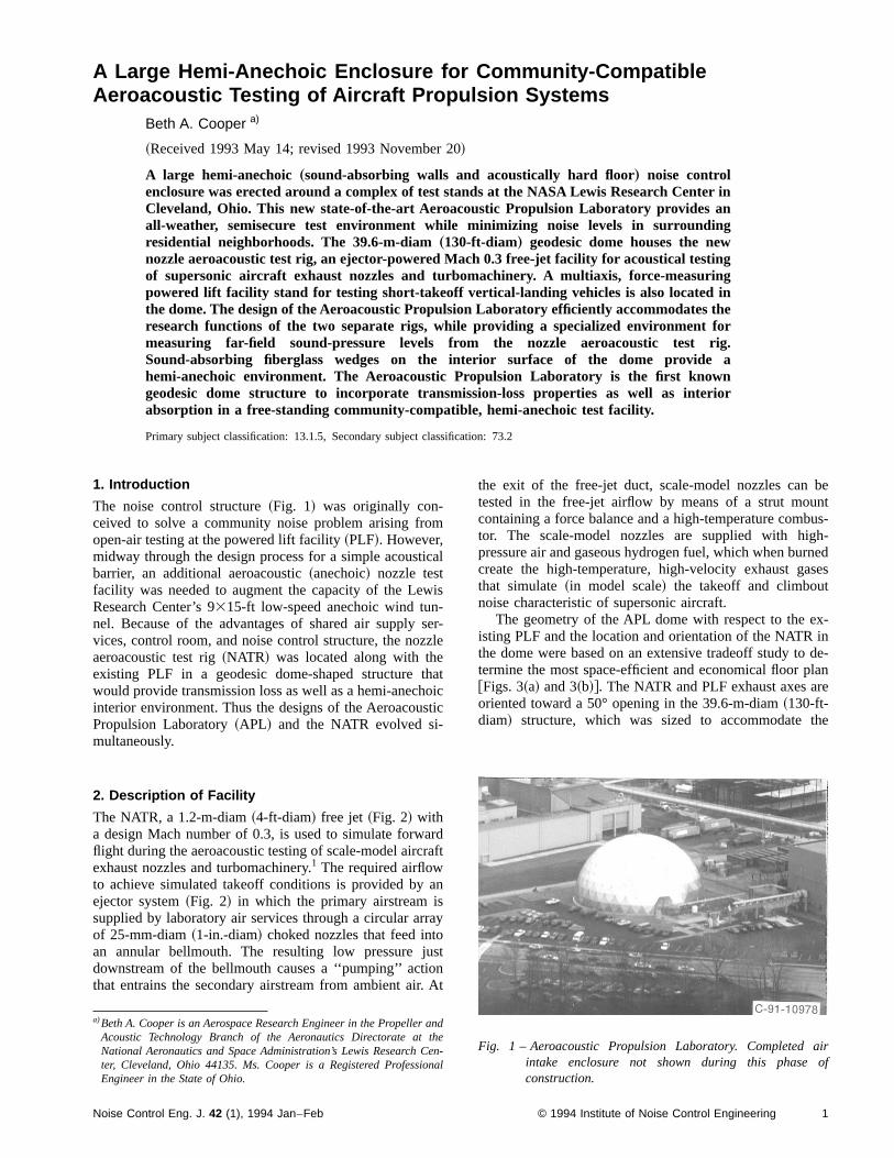
The noise control structure~Fig. 1! was originally con-ceived to solve a community noise problem arising fromopen-air testing at the powered lift facility~PLF!. However,midway through the design process for a simple acousticalbarrier, an additional aeroacoustic~anechoic! nozzle testfacility was needed to augment the capacity of the LewisResearch Center’s 9315-ft low-speed anechoic wind tun-nel. Because of the advantages of shared air supply ser-vices, control room, and noise control structure, the nozzleaeroacoustic test rig~NATR! was located along with theexisting PLF in a geodesic dome-shaped structure thatwould provide transmission loss as well as a hemi-anechoicinterior environment. Thus the designs of the AeroacousticPropulsion Laboratory~APL! and the NATR evolved si-multaneously.
2. Description of Facility
The NATR, a 1.2-m-diam~4-ft-diam! free jet~Fig. 2! witha design Mach number of 0.3, is used to simulate forwardflight during the aeroacoustic testing of scale-model aircraftexhaust nozzles and turbomachinery.1 The required airflowto achieve simulated takeoff conditions is provided by anejector system~Fig. 2! in which the primary airstream issupplied by laboratory air services through a circular arrayof 25-mm-diam~1-in.-diam! choked nozzles that feed intoan annular bellmouth. The resulting low pressure justdownstream of the bellmouth causes a ‘‘pumping’’ actionthat entrains the secondary airstream from ambient air. At
the exit of the free-jet duct, scale-model nozzles can betested in the free-jet airflow by means of a strut mountcontaining a force balance and a high-temperature combus-tor. The scale-model nozzles are supplied with high-pressure air and gaseous hydrogen fuel, which when burnedcreate the high-temperature, high-velocity exhaust gasesthat simulate~in model scale! the takeoff and climboutnoise characteristic of supersonic aircraft.
The geometry of the APL dome with respect to the ex-isting PLF and the location and orientation of the NATR inthe dome were based on an extensive tradeoff study to de-termine the most space-efficient and economical floor plan@Figs. 3~a! and 3~b!#. The NATR and PLF exhaust axes areoriented toward a 50° opening in the 39.6-m-diam~130-ft-diam! structure, which was sized to accommodate the
a)Beth A. Cooper is an Aerospace Research Engineer in the Propeller andAcoustic Technology Branch of the Aeronautics Directorate at theNational Aeronautics and Space Administration’s Lewis Research Cen-ter, Cleveland, Ohio 44135. Ms. Cooper is a Registered ProfessionalEngineer in the State of Ohio.
Fig. 1 – Aeroacoustic Propulsion Laboratory. Completed airintake enclosure not shown during this phase ofconstruction.
1Noise Control Eng. J. 42 (1), 1994 Jan–Feb © 1994 Institute of Noise Control Engineering

exhaust plumes of both rigs as well as operational vehiclesrequiring access. The free jet is positioned such that, duringscale-model nozzle testing, the model-nozzle exit plane islocated close to the dome center, providing a clear line ofsight to microphone arrays located in the NATR half of thedome; thus far-field sound-pressure levels can be measuredin a 120° sector off the nozzle exhaust axis@Fig. 3~b!#.Typically, during nozzle testing, far-field, high-frequencysound-pressure signals are measured with an array of polemicrophones~Fig. 4! at the nozzle centerline height posi-tioned at 10° increments along a polar arc at a 15.2-m~50-ft! radius. Microphones mounted inverted at 5 mm abovethe concrete ground plane, at equivalent radii and solidangles, are used to acquire low-frequency signals that arefree of the ambiguity caused by ground reflections. A 32-channel computerized data acquisition and processingsystem2 provides narrow-band and one-third-octave-bandspectral analysis with compensation for shear layer effects,3
microphone frequency response, and directivity and correc-tion to sea level standard day conditions. This system
Fig. 2 – Nozzle aeroacoustic test rig simulates forward flight foraeroacoustic testing of scale-model nozzles and turboma-chinery. Ejector nozzles (upstream end) supply primaryairstream for NATR.
Fig. 4 – Typical microphone array configuration employed duringaeroacoustic testing of nozzles.
Fig. 5 – NASA Lewis Research Center and surrounding areas.Exhaust axes of NATR and PLF facilities are directedtoward Cleveland Hopkins Airport. Affected residentialcommunities are located approximately 1/2 mile away.
Fig. 3 – Interior of Aeroacoustic Propulsion Laboratory. (a)Nozzle aeroacoustic test rig (left) and powered lift facil-ity (right). Photo taken during construction phase. (b)Floor plan of APL showing location and orientation ofNATR and PLF facilities in dome footprint.
2 Noise Control Eng. J. 42 (1), 1994 Jan–Feb

allows for next day turnaround of processed data, providingtimely support for test program decision making.
3. Development of Noise Control Requirements
Noise control requirements for the APL were the result of ahistory of complaints from neighboring residential commu-nities ~Fig. 5! during a short-takeoff vertical-landing air-craft development program from 1987 to 1988. Althoughthe exhaust axis of the PLF is directed toward ClevelandHopkins Airport and away from residential areas, com-plaints received during approximately 30% of PLF test ses-sions over a 13-month period repeatedly forced PLF per-sonnel to suspend operations. To restore testingproductivity, a plan was developed for permanently reduc-ing community noise levels during testing.
A review of the literature on community and airportnoise research suggested that, in order to minimize com-plaints from the nearby residential community, maximumnoise levels and operational procedures during testingshould result in an A-weighted day–night average soundlevel no greater than 60 dB in residential areas.4–6 Day–night average sound level, a time-integrated noise-evaluation quantity commonly used in community noiseand airport noise studies, reflects a community’s cumulativeexposure to a variety of noise sources over a 24-h periodand includes a 10-dB weighting for sounds occurring atnight. Both in the residential area adjacent to NASA LewisResearch Center and nationally, a day–night average soundlevel of 60 dB is typical of noise ordinances for communi-ties with published numerical noise ordinances. Additionalweightings are often applied to predicted day–night aver-age sound levels in an attempt to account for demographic
Fig. 6 – Dome wall panels provide STC 55 noise attenuation per-formance. (a) Wall panel construction. (b) The multilayersandwich panels fit in the 203-mm (8-in.) channels in thedome structural I beams. (c) Completed dome with inte-rior aluminum skin partially installed.
3Noise Control Eng. J. 42 (1), 1994 Jan–Feb

factors that may make a particular community more or lessreceptive to the noise source. Demographic information andexisting contours of day–night average sound level for theaffected neighborhoods were obtained and used for thispurpose.7,8
The community-compatibility plan involved adoptingsome immediate changes in operational procedures~effec-tively lowering day–night average sound levels! as well asdeveloping a long-term solution for containing the noise ina manner that would not compromise research objectives.In order to ensure unrestricted testing of sound sources thatgenerate high sound-pressure levels, the noise control struc-ture was designed to accommodate noise generated by anF110 aircraft engine. Received spectra in a number ofneighboring communities surrounding the source werepredicted using one-third-octave-band far-field sound-pressure levels~provided by the engine manufacturer! at
10° increments in directivity along a circular arc around anF110 engine at intermediate power. Wave-divergence andminimum-attenuation atmospheric absorption effects9 wereassumed over the distance between the source and thenearest residential neighborhood at each angle. Corre-sponding neighborhood-dependent day–night averagesound levels were then computed for typical operationalprocedures~e.g., the number and duration of individualnozzle tests per test session as well as the temporal andspectral quality of the noise!. Source noise attenuation re-quirements to achieve these day–night average sound lev-els were computed on a one-third-octave-band sound-pressure level basis at each increment of 10° directivityangle around the engine.
4. Design of APL Structure to Meet CommunityNoise Goals
Each APL dome wall panel was designed to provide a noisereduction equal to the maximum of the calculated noisereduction required over the range of directivity angles en-compassed by the residential neighborhoods. A sound trans-mission class~STC! requirement of 55 was determined10
such that noise reduction requirements would be met at allone-third octave bands below 20 kHz. The custom-designed multilayer ‘‘sandwich’’ panels@Figs. 6~a!–6~c!#were tested~per ASTM E-90-75!11 by an independentacoustical laboratory prior to the dome construction. Eachsandwich consists of two aluminum panels of differentthicknesses~exterior, 1.8 mm or 0.07 in.; interior, 4.8 mmor 0.19 in.! separated by a 152-mm~6-in.! airspace contain-ing 51 mm ~2 in.! of thermal insulating wool~fiberglass!.The exterior surface of the dome is covered by a thin alu-minum skin under which the individual sandwich panelsare enclosed and acoustically sealed~with a silicone seal-ant! in the ;203-mm-deep~;8-in.-deep! channels of thedome structural beams@Figs. 6~b! and 6~c!#.
Secondary air for the ejector-powered free jet is en-trained from ambient~outdoor air! through a noise-attenuating, low-pressure-drop air intake [email protected]~a! and 7~b!#. The enclosure is designed to provide therequired airflow area as well as a reduction of forward-quadrant noise generated by the annulus of ejector nozzles.Outdoor air entrained by the ejector flows into the bell-mouth through a wall of double-stacked, noise-attenuatinglouvers@Fig. 7~b!#, each of which consists of a cascade ofparallel airfoil-shaped splitters filled with sound-absorbing
TABLE 1 – Installed noise reduction of Aeroacoustic Propulsion Labora-tory dome structure.
Octave midbandfrequency, Hz
Noise reduction,dB
500 24a
1000 222000 394000 408000 48
16 000 48a
aReceived levels were within 3 dB of background noise level.
Fig. 7 – Noise-attenuating air intake enclosure. (a) Exterior viewof APL showing enclosure. (b) Interior view of enclosureshowing noise-attenuating louvers (taken prior to con-struction of self-noise-attenuating ejector enclosure).
4 Noise Control Eng. J. 42 (1), 1994 Jan–Feb
material. The remaining walls of the air intake enclosureare designed to acoustically and visually match the con-struction of the dome. Noise reduction requirements for theair intake enclosure were specified so that the ejectornozzle noise attenuated by the louvers would be reduced tothe same level in the community as the test nozzle noiseattenuated by the dome wall panels.
Noise levels measured during initial NATR checkouttests in the Spring of 1992 indicated that the dome wallpanels provided the noise reduction shown in Table 1. Re-ceived sound levels in the nearest residential neighbor-hoods were not detectable above the background noiselevel during these or subsequent tests with a nozzle soundsource; in addition, no noise complaints have been receivedsince the completion of dome construction.
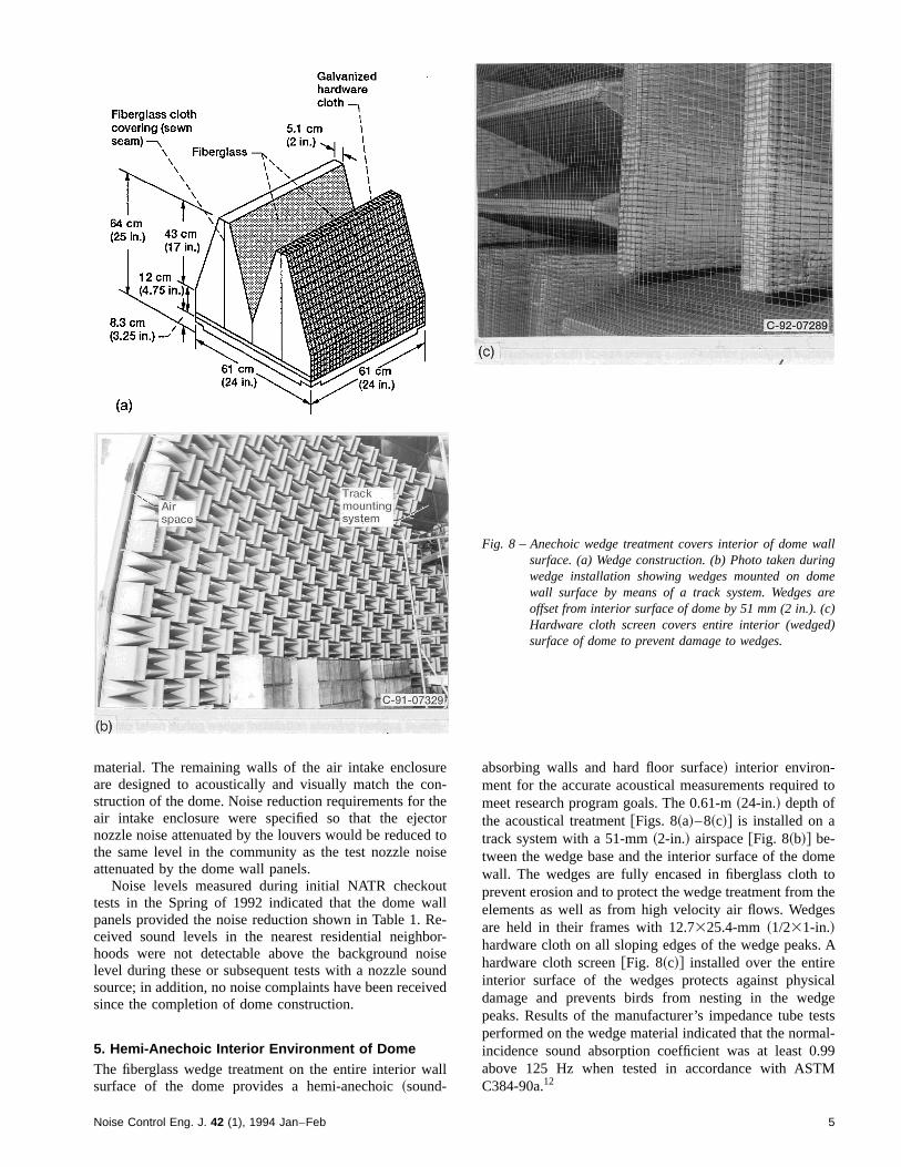
5. Hemi-Anechoic Interior Environment of DomeThe fiberglass wedge treatment on the entire interior wallsurface of the dome provides a hemi-anechoic~sound-
absorbing walls and hard floor surface! interior environ-ment for the accurate acoustical measurements required tomeet research program goals. The 0.61-m~24-in.! depth ofthe acoustical treatment@Figs. 8~a!–8~c!# is installed on atrack system with a 51-mm~2-in.! airspace@Fig. 8~b!# be-tween the wedge base and the interior surface of the domewall. The wedges are fully encased in fiberglass cloth toprevent erosion and to protect the wedge treatment from theelements as well as from high velocity air flows. Wedgesare held in their frames with 12.7325.4-mm ~1/231-in.!hardware cloth on all sloping edges of the wedge peaks. Ahardware cloth screen@Fig. 8~c!# installed over the entireinterior surface of the wedges protects against physicaldamage and prevents birds from nesting in the wedgepeaks. Results of the manufacturer’s impedance tube testsperformed on the wedge material indicated that the normal-incidence sound absorption coefficient was at least 0.99above 125 Hz when tested in accordance with ASTMC384-90a.12
Fig. 8 – Anechoic wedge treatment covers interior of dome wallsurface. (a) Wedge construction. (b) Photo taken duringwedge installation showing wedges mounted on domewall surface by means of a track system. Wedges areoffset from interior surface of dome by 51 mm (2 in.). (c)Hardware cloth screen covers entire interior (wedged)surface of dome to prevent damage to wedges.
5Noise Control Eng. J. 42 (1), 1994 Jan–Feb

Potentially reflective surfaces on internal dome struc-tures were covered or shielded with a variety of sound-absorbing materials to ensure a high-quality acoustical en-vironment. In particular, the exterior surfaces of the NATRwere covered with sound-absorbing blankets; a free-standing, fiberglass-faced wall prevents reflected sound
from the PLF@Fig. 3~a!#; facility instrumentation such aspole microphone stands were wrapped with sound-absorbing material. Facility lighting and video cameraswere selected for low frontal area and were recessed in thewedged interior walls to be acoustically unobtrusive. In ad-dition, electrical conduit and junction boxes were installedbehind the wedges, the access to which is provided bycustom-wedged doors. Evaluation of the interior acousticalenvironment will be included in a series of facility qualifi-cation procedures to be performed pending completion~inearly 1994! of all internal facility systems installations andcheckouts.
To further maintain the research-quality interior acousti-cal environment, facility self-noise levels were minimizedby requiring safety and operational systems to meet strict
Fig. 9 – Noise-attenuating enclosure. (a) Enclosure surroundsejector system to contain and shield microphones fromejector self-noise. (b) Wedged roll-away, plug-style doorsprovide access to interior of enclosure for NATR systemsmaintenance.
Fig. 10 – Safety-mandated fan provides quiet continuous ventila-tion during nozzle testing. (a) Fan housing mountedabove (exterior to) dome surface. (b) Interior view offan opening, treated with anechoic wedges to preventreflections from top of dome.
6 Noise Control Eng. J. 42 (1), 1994 Jan–Feb
noise criteria for direct and reflected sound, specifically20 dB below the predicted one-third-octave-band sound-pressure levels for a typical noise-suppressor nozzle. TheNATR itself is by design a low self-noise system: aft-quadrant self-noise generated by the annulus of ejectornozzles is attenuated as it travels downstream through theNATR by sound-absorbing treatment in the walls of thediffuser and plenum sections. The microphone arrays areshielded from direct, radiated, aft-quadrant ejector self-noise by a sealed noise-attenuating~STC 54! enclosure thatsurrounds the ejector portion of the NATR@Figs. 9~a! and9~b!#. To prevent reflections, the exterior surfaces of thisenclosure are covered with wedges. A fan~producing a vol-ume flow rate of 18.9 m3/s or 40 000 ft3/min! at the top ofthe dome@Figs. 10~a! and 10~b!# provides the continuousexhaust~mandated for safety reasons while the NATR fa-cility is burning gaseous hydrogen fuel! and also meets the20-dB noise-reduction criterion.
The acoustical integrity of the facility was of primaryimportance during the process of new equipment installa-tions and facility modifications; each action was consideredwith regard to its impact on the research quality of theacoustical environment. Further facility upgrades andmodifications to accommodate new test programs on boththe PLF and the NATR will again be accomplished in anacoustically responsible manner.
6. Summary
The all-weather, semisecure geodesic dome structure of theAeroacoustic Propulsion Laboratory at the NASA LewisResearch Center achieved the goal of reducing noise levelsin adjacent residential communities while providing a
research-quality hemi-anechoic interior environment for theacoustical testing of supersonic aircraft exhaust nozzles.During initial checkout testing, the dome performed as ex-pected; community noise levels were significantly reducedand complaints have been eliminated since the facility wascompleted.
7. References1M. Long-Davis and B. Cooper, ‘‘LeRC NATR free-jet development,’’presented at the NASA/Industry HSR Nozzle Symposium~1992!.
2D. J. Hall and J. Bridges, ‘‘A sophisticated, multi-channel data acquisi-tion and processing system for high frequency noise research,’’ NASAContractor Report CR-189137~1992!.
3R. Schlinker and R. Amiet, ‘‘Refraction and scattering of sound by ashear layer,’’ NASA Contractor Report CR-3371~1980!.
4 ‘‘Information on levels of environmental noise requisite to protect publichealth and welfare with an adequate margin of safety,’’ EnvironmentalProtection Agency Report No. PB-239 429/4 EPA-550/9-74-004~1974!.
5L. L. Beranek,Noise and Vibration Control~Institute of Noise ControlEngineering, Washington, DC, 1988!.
6C. M. Harris,Handbook of Acoustical Measurements and Noise Control,3rd ed.~McGraw-Hill, New York, 1991!.
7 ‘‘FAR 150 airport noise compatibility program,’’ City of Cleveland De-partment of Port Control, Cleveland, OH~1985!.
8 ‘‘FAR Part 150 noise exposure map project,’’ City of Cleveland Depart-ment of Port Control, Cleveland, OH~1984!.
9 ‘‘Standard values of atmospheric absorption as a function of temperatureand humidity,’’ ARP 866A, Society of Automotive Engineers, Warren-dale, PA~1975!.
10‘‘Classification for rating sound insulation,’’ ASTM E-413-87, AmericanSociety for Testing and Materials, Philadelphia, PA~1992!.
11‘‘Standard method for laboratory measurement of airborne sound trans-mission loss of building partitions,’’ ASTM E-90-90, American Societyfor Testing and Materials, Philadelphia, PA~1992!.
12‘‘Standard test method for impedance and absorption of acoustical ma-terials by the impedance tube method,’’ ASTM C-384-90a, AmericanSociety for Testing and Materials, Philadelphia, PA~1992!.
7Noise Control Eng. J. 42 (1), 1994 Jan–Feb