a l l - i n - o n e l i q u i d c p u c o o l e r manual.pdf · intel® lga...
TRANSCRIPT

A l l - I N - O N E L I Q U I D C P U C O O L E R

Limited Warranty
Specification
Part list
Intel Installation
RGB Control Box
Refilling Coolant
1
2
3
4
17
21
Index

Please read this limited warranty carefully. Warranty is subject to void under following criteria:1. The serial number label or warranty seal is defaced, modified, or removed.2. Taking apart of the product and/or modification of any component or cable without ENERMAX’s written authorization.3. Ignoring connector’s faulty-insertion-prevention design by attaching a connector to a device under incorrect orientation.4. Damage caused by natural phenomena or uncontrollable forces, such as lightning, flooding, fire, earthquake, or misuse, abuse, negligence, accident, wear and tear, mishandling, misapplication.5. ENERMAX is only liable for limited warranty service of ENERMAX product. ENERMAX is not liable for other damage or loss of time, interest, commercial opportunity due to using defect product of ENERMAX.
This ENERMAX Technology Corporation product is warranted to be free from defects in material and workmanship for a period of two (2) years from the date of purchase. ENERMAX Technology Corporation agrees to repair or replace the product, at its own option and at no charge, if, during the warranty period, it is returned to nearest ENERMAX Technology Corpora-tion subsidiary/agent with all shipping charges prepaid and if inspection reveals that the product is defective. Please present the proof of purchase for requesting RMA. Charges for removing or installing the product are excluded under the terms of this warranty agreement. This warranty shall not apply to any product, which has been subject to connection to a faulty power source, alteration, negligence, or accident, or to any product, which has been installed other than in accordance with these instructions. In no event shall ENERMAX Technology Corporation, or its subsidiaries, or agents be liable for damages for a breach of warranty in an amount exceeding the purchase price of this product.
If you are uncertain whether or not your ENERMAX liquid cooler is defective, please contact your dealer/reseller for support!Web Site: http://www.enermax.comE-mail: [email protected]
ENERMAX Technology Corporation, 15F-2, No. 888, Jing-Guo Road, Taoyuan City (330), Taiwan (R.O.C.), Tel. +886-3-316-1675, Fax. +886-3-346-6640
©2018 ENERMAX Technology Corporation. All rights reserved. Specifications are subject to change without prior notice. Actual product and accessories may differ from illustrations. Omissions and printing errors excepted. Content of delivery might differ in different countries or areas. Some trademarks may be claimed as the property of others. Reproduction in any manner without the written permission of ENERMAX is strictly forbidden.
- 1 -
Limited Warranty

Model ELC-LF240-RGB
Intel® LGA 775/1150/1151/1155/1156/1366/2011/2011-3/2066AMD® AM2/AM2+/AM3/AM3+/AM4/FM1/FM2/FM2+
Fan
Air Flow
Static Pressure
Noise Level
Connector
Material
Bearing
MTBF
Motor Speed
Rated Voltage
Rated Current
Dimension
Material
Material
Length
Thermal Grease
Pump
Copper base with Aluminum Radiator
Ceramic bearing
50,000 hrs
5000 rpm ± 10%
12V
0.18A
270 x 120 x 27 mm
Aluminum
Rubber
400 mm
0.99kgs
120 x 120 x 25 mm
500 - 2000 RPM (±10%)
12V
0.3A
23.81 ~ 102.17 CFM
40.45 ~ 173.59 m3/h
0.673 ~ 6.28 mm-H2O
14 ~ 28 dBA
4 Pin PWM + 4 Pin RGB
Dow Corning® TC-5121C
Radiator
Tube
Weight (W/O fan)
Compatibility
Dimension
Speed
Rated Voltage
Rated Current
- 2 -
Specification

A Cooler x 1 B Fan x 2 C Back Plate x 1
E Position Screw x 4 F Stand-off x 4 H Fan Screw x 8G Case Screw x 8
K PWM Y cable x 1
R 24P Power Adaptor x 1
N Thermal Grease x 1
Q RGB Controller Power cable (SATA) x 1
O RGB Control Box x 1 P RGB Sync cable x 1
J Washer x 4 L Molex Adaptor x 1 M Scraper x 1
I Set Screw x 4
D Position Plate x 1
Maintenance Kit
Please refill the coolant, when the flow indicator is not rotating. (please see page 21 for more information)Coolant 100ml x 1
(1g thermal grease x 1)
- 3 -
Part List

Installation
- 4 -
A l l - I N - O N E L I Q U I D C P U C O O L E R

A B H
EN
DE
FR
IT
ES
PL
TW
CN
ID
JP
KR
Attach the fan and the radiator to the chassis
Schrauben Sie den Lüfter und den Radiator am Gehäuse fest.
Fixez le ventilateur et le radiateur sur le châssis
Fissare la ventola e il radiatore al case
Fijar el ventilador y el radiador a la caja
Zamontuj wentylator i radiator na obudowie komputerowej.
安裝風扇及散熱排於機殼
将风扇以及散热排安装在机箱上
ファンをラジエーターに設置してケースに取り付けて下さい。
팬과 방열기를 PC 케이스에 부착하십시오.
Pasang kipas dan radiator ke casing
- 5 -
InstallationStep 1

EN
DE
FR
IT
ES
PL
TW
CN
ID
JP
KR
LGA775LGA115XLGA1366
All AM2/AM3/FM1/FM2 bracket
E
C
AM4
Insert the position screws into the proper holes on the back plate. Then use the washers to fix the position screws. (If your CPU platform is Intel LGA 2011/2011-3/2066, please skip to step 2-B)
Stecken Sie die Positionsschrauben in die entsprechenden Löcher auf der Backplate passend zu Ihrenm CPU-Sockel. (Wenn Ihr CPU-Sockel Intel LGA 2011/2011-3/2066 ist, fahren Sie bitte mit Schritt 2-B fort).
Installez les vis de position dans les trous appropriés sur la plaque arrière. Ensuite, utilisez les rondelles pour fixer les vis de position. (Si votre socket du processeur est Intel LGA 2011/2011-3/2066, passez à l'étape 2-B)
Inserire le viti di posizione nei fori appropriati sul back plate per il socket della vostra CPU (se la vostra piattaforma CPU è Intel LGA 2011/2011-3/2066 si prega di andare direttamente allo step 2-B).
Colocar los tornillos de posición en los agujeros adecuados para el zócalo de su CPU en el back plate ( si la plataforma de su CPU es Intel LGA 2011/2011-3/2066 se ruega ir directamente a la fase 2-B).
Wsuń śruby pozycjonujące do odpowiednich otworów w tylnej płytce dla odpowiedniego gniazda CPU. (W przypadku platformy CPU Intel LGA 2011/2011-3/2066 przejdź od razu do czynności 2-B)
在背板上依系統 CPU 腳位所標示的孔位插入定位螺絲並套上墊圈固定 (如您的主機板是Intel LGA 2011/2011-3/2066,請直接跳至步驟 2-B)。
在背板上根据系统 CPU 脚位所标示的孔位插入定位螺丝并套上垫圈固定 (如您的主机板是Intel LGA 2011/2011-3/2066,请直接跳至步骤 2-B)。
CPUソケットに合った Back Plateの取付穴をご確認いただき、Position Screwを差し込みます。(CPUソケットがIntel LGA 2011/2011-3/2066の場合は、ステップ2-Bへお進み下さい)
백 플레이트의 적절한 구멍에 포지션 나사를 위치시키십시오. 와셔를 이용하여 포지션 나사를 고정하십시오. (CPU 플랫폼 Intel LGA 2011/2011-3/2066 사용자라면, step 2-B로 가십시오)
Masukkan sekrup posisi ke lubang yang tepat pada back plate. Kemudian gunakan washers/cincin penutup untuk memperbaiki sekrup posisi.(Jika platform CPU anda adalah Intel LGA 2011/2011-3/2066, lompatlah ke langkah 2-B)
- 6 -
InstallationStep 2-A-1

EN
DE
FR
IT
ES
PL
TW
CN
ID
JP
KR
Install the back plate on the back of motherboard, place the washer into the position screw and fix them with stand-off.
Installieren Sie die Backplate auf der Rückseite des Mainboards, legen Sie die Unterlegscheibe auf die Positionsschraube und fixieren Sie sie mit dem Abstandshalter.
Installez la plaque arrière (C) sous la carte-mère, placez les rondelles (J) dans les vis (E) de position puis fixez-les avec les écrous (F) boulons.
Installare il back plate nella parte posteriore della scheda madre, posizionare le rondelle sulle viti di posizione e fissarle con i distanziali.
Instalar el back plate en la parte posterior de la placa base, colocar las arandelas en los tornillos de posición y fijarlos con los separadores.
Przyłóż płytkę tylną do odwrotnej strony płyty głównej, nałóż podkładkę na śrubę pozycjonującą i dokręć je do tulejki dystansowej.
將背版置入主機板背面,將墊片套入定位螺絲,並鎖上螺柱以固定背板。
将背板置入主板背面,将垫片套入定位螺丝,并锁上螺柱以固定背板。
Back Plateをマザーボードの裏側にセットし、表側に出たPosition Screw にWasherとStand offを挿し込んでください。
백 플레이트를 (C) 마더보드 후면에 설치 한 후, 와셔를 (J) 나사 (E) 위치에 놓은 후 지지대를 (F) 이용해 고정하십시오.
Pasang back plate pada belakang motherboard, letakkan washer ke sekrup posisi dan kencangkan dengan stand off.
F
J
C
- 7 -
InstallationStep 2-A-2

EN
DE
FR
IT
ES
PL
TW
CN
ID
JP
KR
Place position plate on stand-off and use set screw to fix.
Legen Sie die Positionsplatte auf die Abstandshalter und verwenden Sie die Feststellschrauben zum Fixieren.
Placez la plaque (D) de position sur les écrous (F) boulons et utilisez les vis (I) pour les fixer.
Collocare la piastra di posizione sui distanziali e utilizzare le viti per fissare.
Colocar la placa de posición en los separadores y usar los tornillos para fijar.
Umieść płytkę pozycjonującą na tulejce dystansowej i przykręć śrubą mocującą.
請於螺柱上放置固定板後,用固定螺絲鎖上。
请在螺柱上放置固定板后,用固定螺丝锁上。
Position PlateをStand offの上にセットし、Set Screwで固定してください。
지지대 (D) 위에 포지션 플레이트를 (F) 위치 시킨 후 세트 나사로 (I) 고정하십시오.
Letakkan pelat posisi pada stand off dan gunakan sekrup set untuk memperbaiki.
F
D
I
- 8 -
InstallationStep2-A-3

LGA 2011 /2011-3 / 2066
EN
DE
FR
IT
ES
PL
TW
CN
ID
JP
KR
Place position plate on stand-off and use position screw to fix. (Socket LGA 2011/2011-3/2066 does not require the back plate).
Legen Sie die Positionsplatte auf die Abstandshalter und verwenden Sie die Positionsschrauben zum Fixieren. (Socket LGA 2011/2011-3/206 benötigt keine Backplate).
Placez (D) la plaque de position sur (F) les écrous boulons et utilisez les (E) vis de position pour les fixer, (Socket LGA 2011/2011-3/2066 ne nécessite pas la plaque arrière).
Collocare la piastra di posizione sui distanziali e utilizzare le viti per fissare. (il Socket LGA 2011/2011-3/2066 non necessita del back plate).
Colocar la placa de posición en los separadores y usar los tornillos para fijar. (el Socket LGA 2011/2011-3/2066 no necesita del back plate)
Umieść płytkę pozycjonującą na tulejce dystansowej i przykręć śrubą pozycjonującą. (Gniazdo LGA 2011/2011-3/2066 nie wymaga płytki tylnej).
請於螺柱上置放固定板後,用定位螺絲鎖上。(LGA 2011/2011-3/2066主機板不需使用背板)
请在螺柱上置放固定板后,用定位螺丝锁上。(LGA 2011/2011-3/2066主板不需使用背板)
Position PlateをStand offの上にセットし、Position Screwで固定してください。(LGA 2011/2011-3/2066ソケットの場合、バックプレートは必要ありません)
지지대 위에 포지션 플레이트를 (D) 위치 시킨 (F) 후 세트 나사로 (E)고정하십시오. (LGA 2011/2011-3/2066 소켓이라면, 백 플레이트 설치는 해당사항 아닙니다)
Letakkan pelat posisi pada stand off dan gunakan sekrup posisi untuk memperbaiki.(Socket LGA 2011/2011-3/2066 tidak memerlukan back plate)
E
D
F
- 9 -
InstallationStep2-B

EN
DE
FR
IT
ES
PL
TW
CN
ID
JP
KR
Apply the thermal grease evenly on the CPU surface
Verteilen Sie gleichmäßig eine dünne Schicht Wärmeleitpaste auf der CPU-Oberfläche.
Appliquez une couche uniforme de pâte thermique sur la surface du CPU
Applicare in modo uniforme la pasta termica sulla superficie della CPU
Aplicar de forma uniforme la pasta térmica en la superficie de la CPU
Nałóź równomiernie cienką warstwę pasty termoprzewodzącej na metalową osłonę na procesorze.
將散熱膏均勻的塗抹於CPU表面。
请在CPU表面均与涂抹散热硅脂。
サーマルグリスをCPUの表面に均一になるよう薄く塗って下さい。
CPU 표면에 구리스를 평평히 펴 바르십시오.
Oleskan secara merata thermal pasta ke permukaan CPU
- 10 -
InstallationStep 3

EN
DE
FR
IT
ES
PL
TW
CN
ID
JP
KR
Remove the protect film from the cold-plate.
Entfernen Sie die Schutzfolie von der Kühlplatte der Pumpe.
Retirez le film protecteur de la plaque-froide.
Rimuovere la pellicola di protezione dalla piastra di raffreddamento.
Quite la película de protección del bloque de refrigeración.
Zdjąć folię ochronną z bloku wodnego.
取下水冷頭保護貼膜。
使用时请将水冷头保护贴膜取下。
コールドプレートの保護フィルムを外して下さい。
콜드 플레이트의 보호 필름을 제거하십시오. Lepaskan pita pelindung dari plat pendingin.
- 11 -
InstallationStep 4

EN
DE
FR
IT
ES
PL
TW
CN
ID
JP
KR
Place the waterblock on the CPU and tighten the two screws.
Setzen Sie den Wasserblock auf die CPU und ziehen Sie die beiden Schrauben fest.
Placez la waterblock sur le CPU et serrez les 2 vis.
Posizionare il waterblock sulla CPU e avvitare le due viti.
Posicionar el bloque de refrigeración en la CPU y fijar los dos tornillos.
Ustaw blok wodny na CPU i dokręć dwoma śrubami.
請將水冷頭放置CPU上並鎖上兩邊的螺絲固定。
请将水冷头放置CPU上并锁上两边的螺丝固定。
水冷ヘッドの固定ネジをPosition Plateのネジ穴の向きに合わせ、水冷ヘッドをCPUの上に設置し、2本の固定ネジを均等に締め付けて固定します。
CPU 위에 워터블럭 놓고 나사 2개를 단단히 고정하십시오.
Tempatkan pompa pada CPU dan kencangkan kedua baut.
- 12 -
InstallationStep 5

EN
DE
FR
IT
ES
PL
TW
CN
ID
JP
KR
Connect the pump power connector to the motherboard.Notice: If you recognize that your mainboard's CPU fan or PWM sockets do not provide enough voltage to power the pump, please use the included 4-pin Molex adaptor and connect the pump directly to your PSU.
Schließen Sie den Stromstecker der Pumpe am Mainboard an.Hinweis: Wenn Sie bemerken, dass die CPU-Fan- und PWM-Sockel Ihres Mainboards für den Betrieb der Pumpe eine zu geringe Spannung erreichen, schließen Sie diese bitte über den mitgelieferten 4-Pin-Molex-Adapter direkt an das Netzteil an.
Branchez le connecteur d'alimentation de la pompe à la carte-mère.Remarque: Si vous constatez que le connecteur du ventilateur CPU ou le PWM de la carte mère ne fournissent pas suffisamment de courant à la pompe, nous vous recommandons d'utiliser le câble adaptateur 4 broches Molex inclus que vous connecterez à l'alimentation.
Collegare il connettore di alimentazione della pompa alla scheda madre.Avviso: se notate che il socket PWM o il socket per la ventola della CPU non forniscono un tensione sufficiente per alimentare la pompa, si prega di utilizzare l’adattatore Molex a 4 pin in dotazione e collegare la pompa direttamente alla PSU.
Conecte el cable de la bomba a la placa madre.Aviso: Si se nota que el enchufe PWM o el enchufe para el ventilador de la CPU no proporcionan suficiente voltaje para alimentar la bomba, se ruega utilizar el adaptador Molex de 4 patillas incluido y conectar la bomba directamente a la fuente de alimentación.
Podłącz wtyczkę do zasilania pompy do plyty głównej.Uwaga: Jeśli gniazda płyty głównej „CPU Fan” oraz PWM nie zapewniają wystarczającego napięcia do zasilania pompy, proszę podłączyć pompę bezpośrednio do zasilacza za pomocą 4-pinowego adaptera Molex.
連接水泵電源於主板注意:為確保水泵維持長時間全速運轉,若您主機板上的CPU風扇或PWM插座未能提供足夠電壓驅動水泵時,建議您使用內附4pin轉接線連接至電源供應器,以達到產品最佳效能。
请将水泵电源与主板相应供电口连接警告:为确保水泵能长时间全速运转,若您主板上的CPU风扇或者PWM接口不能提供足够电压带动水泵,建议使用内附4pin转接线连接至电源,以达到产品最佳效能。
水冷ポンプのコネクターをマザーボードに接続して下さい。注意:ご使用のマザーボードのCPUファンコネクターまたはPWMファンコネクターがポンプに十分な電圧を供給しない場合は、付属の4-pin Molex変換アダプターをご使用いただき、電源ユニットに直接ポンプを接続してください。
펌프 전원 커넥터를 마더보드에 연결하십시오.주의사항 : 메인보드 CPU Fan 또는 PWM 소켓에 연결 했을 시 충분한 전압을 펌프로 제공을 하지 못하면,별도로 제공한 4핀 Molex 케이블을 이용하여 파워서플라이에 직접연결 하십시요.
Hubungkan konektor daya pompa ke motherboard.Catatan: jika anda menyadari socket power cpu fan atau pwm motherboard anda, tidak bisa memberikan daya yang cukup untuk pompa watercooling, silahkan menggunakan 4pin molex adaptor dan sambungkan langsung ke power PSU.
Pump
4 pin
Pump
3 pin
or
- 13 -
InstallationStep 6

EN
DE
FR
IT
ES
PL
TW
CN
ID
JP
KR
Connect the fan connector to the motherboard
Schließen Sie den 4-Pin-PWM-Stecker des Lüfters am Mainboard an.
Branchez le connecteur du ventilateur à la carte-mère
Collegare il connettore della ventola alla scheda madre
Conecte el conector del ventilador a la placa madre
Podłącz wtyczkę 4-pin PWM wentylatora do płyty głównej.
連接風扇電源於主板
请将风扇电源与主板上的相应供电口连接
ファンコネクターをマザーボードに接続して下さい。
팬 커넥터를 마더보드에 연결하십시오.
Hubungkan konektor kipas ke motherboard
PWM Y cable
4 pin
1st fan 2st fan
- 14 -
InstallationStep 7

EN
DE
FR
IT
ES
PL
TW
CN
ID
JP
KR
Connect the RGB fan and waterblock power connectors to RGB control box. Connect the SATA power cable to PC power supply SATA connector.
Verbinden Sie die RGB-Lüfter- und Wasserblock-Stromanschlüsse mit der RGB-Steuerbox.
Connectez les connecteurs d'alimentation du ventilateur RGB et du Waterblock au boîtier contrôleur RGB, Connectez le câble d'alimentation SATA au connecteur SATA du bloc d'alimentation PC.
Collegare i connettori di alimentazione del waterblock e delle ventole RGB alla centralina.
Conecte los conectores de alimentación del bloque de refrigeración y de los ventiladores RGBa la unidad de control.
Podłącz złącza zasilające wentylatora RGB i bloku wodnego do sterownika RGB.
請將風扇及水冷頭上的RGB連接器連接在RGB同步線;再連接於控制器上。連接控制器電源於電源供應器SATA端。
请将风扇及水冷头上的RGB连接器与RGB同步线连接;并连接于控制器上。再将控制器电源连接到电源供应器SATA端。
ファンRGB&水冷ヘッドRGBケーブルをRGBコントロールボックスに接続してください。
RGB컨트롤 박스와 RGB팬&워터블럭 파워 커넥터와 연결하십시오.
Hubungkan kipas RGB dan konektor power water blok ke kotak kontrol RGB.
Synchronization T.B. RGB Fan and WaterBlock* If the motherboard NOT support the addressable RGB (+5V/D/G).
Connect to RGB control box Fan & WaterBlock
- 15 -
InstallationStep 8

+5V
+5V
D G
Addressable RGB Header
EN
DE
FR
IT
ES
PL
TW
CN
ID
JP
KR
If the motherboard DOES support the addressable RGB: connect the RGB Sync cable to the motherboard.
Wenn das Mainboard adressierbare RGB-Header unterstützt: Verbinden Sie das RGB-Sync-Kabel mit dem Mainboard.
Si la carte mère prend en charge le connecteur RGB: connectez le câble de synchronisation RGB à la carte mère.
Se la scheda madre è fornita di connettori RGB compatibili, collegare il cavo RGB Sync alla scheda madre.
Si su placa base está equipada con conectores RGB compatibles, conecte el cable RGB Sync a la placa base.
Jeśli płyta główna OBSŁUGUJE adresowalne nagłówki RGB: podłącz kabel synchronizacyjny RGB do płyty głównej.
若您的主機板有支援 addressable RGB功能:將RGB同步線連接到主機板的 RGB 4Pin接口。
若您的主机板有支援 addressable RGB功能:将RGB同步线连接到主机板的 RGB 4Pin接口。
マザーボードがアドレッサブル型RGBに対応している場合、RGB SYNC用ケーブルをマザーボードに接続してください。
마더보드가 RGB지원하는 경우: RGB 동조 케이블을 마더보드에 연결하십시오.
Jika motherboard tidak mendukung header RGB yang dapat dialamatkan : sambungkan kabel RGB Sync ke motherboard.
* Please ensure it is properly the connector to the motherboard.
- 16 -
InstallationStep 9

RGB Control Box
- 17 -
For non-addressable RGB motherboard
EN
DE
FR
IT
ES
PL
TW
CN
JP
KR
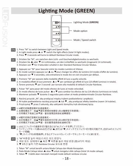
1. Press “M” to switch between Light and Speed mode.2. In Light mode press ▲ or ▼ switch the light effects (total 14 light modes).3. Press ▼ 3 seconds will turns to default Rainbow Circular mode.
1. Drücken Sie "M", um zwischen dem Licht- und Geschwindigkeitsmodus zu wechseln.2. Drücken Sie ▲ oder ▼ im Lichtmodus, um den Lichteffekt zu wechseln (insgesamt 14 Lichtmodi).3. Drücken von ▼ für 3 Sekunden schaltet in den Standard Rainbow Circular Modus.
1. Appuyez sur "M" pour basculer entre les modes Lumière et Vitesse. 2. En mode Lumière appuyez sur ▲ ou ▼pour changer les effets de lumière (14 modes d’effet de lumière). 3. Appuyez sur ▼ 3 secondes, cela entraînera le mode Arc-en-ciel circulaire par défaut.
1. Premere “M” per passare dalla modalità effetti di luce a quella velocità.2. In modalità effetti di luce premere ▲ o ▼ per cambiare gli effetti di luce (14 effetti luminosi in totale).3. Tenere premuto ▼ per 3 secondi per tornare alla modalità di default Circular Rainbow.
1. Pulsar “M” para pasar del modo efectos de luces al modo velocidad.2. En modo efectos de luces pulsar ▲ o ▼ para cambiar los efectos de luz (14 efectos luminosos en total).3. Mantener pulsado ▼ durante 3 segundos para volver al modo predeterminado Circular Rainbow.
1. Naciśnij przycisk „M”, aby przełączyć między trybem podświetlenia i prędkości.2. W trybie podświetlenia naciskaj przyciski ▲ lub ▼ , aby przełączać efekty świetlne (razem 14 trybów).3. Przytrzymaj ▼ przez 3 sekundy, aby uaktywnić domyślny tryb obrotowej tęczy.
1. M鍵可切換燈型模式及速度模式。2. 在燈型模式下,按▲▼鍵可選擇其他燈型 (共14種燈型可供選擇)。3. 任何模式下長按三秒▼鍵,會回復預設的彩虹旋轉燈型。
1. M键可切换灯型模式及速度模式。2. 在灯型模式下,按▲▼键可选择其它灯型 (共14种灯型可供选择)。3. 任何模式下长按三秒▼键,会回复预设的彩虹旋转灯型。
1. LEDとエフェクトの速度を切り替えるには「M」スイッチを押してください。2. ライティングモード(緑LED点灯)では「▲」または「▼」スイッチでエフェクト切り替え可能です。(合計14のエフェクト モード搭載)3. 「▼」スイッチを3秒間長押しするとデフォルトのレインボーサキュラーモードに戻ります。
1. “M”버튼을 눌러 색상/스피드 모드 변경*12. 색상 모드 상태에서 ▲ 혹은 ▼ 버튼을 눌러 색상 변경 (총14가지 색상)3. ▼ 3초간 눌러 기본 Rainbow Circular 모드로 변환
1. Tekan “M” untuk beralih antara Mode Cahaya dan Mode Kecepatan.2. Pada Mode Cahaya tekan ▲ atau ▼untuk mengatur efek cahaya (total 14 mode cahaya).3. Tekan ▼ 3 detik akan merubah menjadi mode default rainbow circular.
Lighting Mode (GREEN)
Mode option
Mode / Speed switch
- 18 -
Lighting Mode (GREEN)
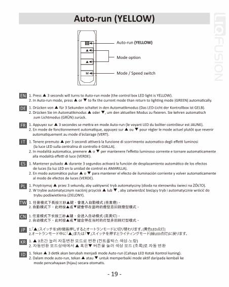
1. Press ▲ 3 seconds will turns to Auto-run mode (the control box LED light is YELLOW).2. In Auto-run mode, press ▲ or ▼ to fix the current mode than return to lighting mode (GREEN) automatically.
1. Drücken von ▲ für 3 Sekunden schaltet in den Automatikmodus (Das LED-Licht der Kontrollbox ist GELB).2. Drücken Sie im Automatikmodus ▲ oder ▼, um den aktuellen Modus zu fixieren. Sie kehren automatisch zum Lichtmodus (GRÜN) zurück.
1. Appuyez sur ▲ 3 secondes se mettra en mode Auto-run (le voyant LED du boîtier contrôleur est JAUNE).2. En mode de fonctionnement automatique, appuyez sur ▲ ou ▼ pour régler le mode actuel plutôt que revenir automatiquement au mode d'éclairage (VERT).
1. Tenere premuto ▲ per 3 secondi attiverà la funzione di scorrimento automatico degli effetti luminosi (la luce LED sulla centralina di controllo è GIALLA).2. In modalità automatica, premere ▲ o ▼ per mantenere l’effetto luminoso corrente e tornare automaticamente alla modalità effetti di luce (VERDE).
1. Mantener pulsado ▲ durante 3 segundos activará la función de desplazamiento automático de los efectos de luces (la luz LED en la unidad de control es AMARILLA).2. En modo automático pulsar ▲ o ▼ para mantener el efecto de iluminación corriente y volver automaticamente al modo de efectos de luces (VERDE).
1. Przytrzymaj ▲ przez 3 sekundy, aby uaktywnić tryb automatyczny (dioda na sterowniku świeci na ŻÓŁTO).2. W trybie automatycznym naciśnij przycisk ▲ lub ▼ , aby zatwierdzić bieżący tryb i automatycznie wrócić do trybu podświetlenia (ZIELONY).
1. 任意模式下長按三秒▲鍵,會進入自動模式 (亮黃燈)。2. 自動模式下,此時按▲或▼鍵會停在當時的燈型並回到燈型模式。
1. 任意模式下长按三秒▲键,会进入自动模式 (亮黄灯)。 2. 自动模式下,此时按▲或▼键会停在当时的灯型并回到灯型模式。
1.「▲」スイッチを3秒間長押しするとオートランモードに切り替わります。(黄色LED点灯)2.オートランモード中に「▲」または「▼」スイッチを押すとライティングモード(緑LED点灯)に戻ります。
1. ▲ 3초간 눌러 자동변환 모드로 변환 (컨트롤박스 색상-노랑)2. 자동변환 모드상태에서 ▲ 혹은▼ 버튼을 눌러 색상 모드 (초록)로 자동 변환
1. Tekan ▲ 3 detik akan berubah menjadi mode Auto-run (Cahaya LED Kotak Kontrol kuning).2. Dalam mode auto-run, tekan ▲ atau ▼ untuk memperbaiki mode aktif daripada kembali ke mode pencahayaan (hijau) secara otomatis.
EN
DE
FR
IT
ES
PL
TW
CN
ID
JP
KR
Auto-run (YELLOW)
Mode option
Mode / Speed switch
- 19 -
Auto-run (YELLOW)
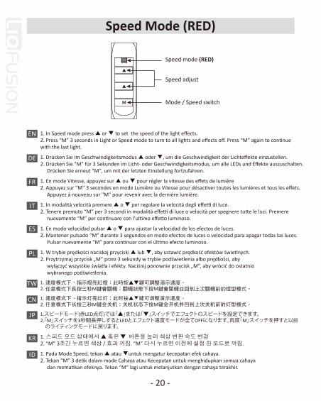
1. In Speed mode press ▲ or ▼ to set the speed of the light effects.2. Press “M” 3 seconds in Light or Speed mode to turn to all lights and effects off. Press “M” again to continue with the last light.
1. Drücken Sie im Geschwindigkeitsmodus ▲ oder ▼, um die Geschwindigkeit der Lichteffekte einzustellen.2. Drücken Sie "M" für 3 Sekunden im Licht- oder Geschwindigkeitsmodus, um alle LEDs und Effekte auszuschalten. Drücken Sie erneut "M", um mit der letzten Einstellung fortzufahren.
1. En mode Vitesse, appuyez sur ▲ ou ▼ pour régler la vitesse des effets de lumière2. Appuyez sur "M" 3 secondes en mode Lumière ou Vitesse pour désactiver toutes les lumières et tous les effets. Appuyez à nouveau sur "M" pour revenir avec la dernière lumière.
1. In modalità velocità premere ▲ o ▼ per regolare la velocità degli effetti di luce.2. Tenere premuto “M” per 3 secondi in modalità effetti di luce o velocità per spegnere tutte le luci. Premere nuovamente “M” per continuare con l’ultimo effetto luminoso.
1. En modo velocidad pulsar ▲ o ▼ para ajustar la velocidad de los efectos de luces.2. Mantener pulsado “M” durante 3 segundos en modo efectos de luces o velocidad para apagar todas las luces. Pulsar nuevamente “M” para continuar con el último efecto luminoso.
1. W trybie prędkości naciskaj przyciski ▲ lub ▼, aby ustawić prędkość efektów świetlnych.2. Przytrzymaj przycisk „M” przez 3 sekundy w trybie podświetlenia albo prędkości, aby wyłączyć wszystkie światła i efekty. Naciśnij ponownie przycisk „M”, aby wrócić do ostatnio wybranego podświetlenia.
1. 速度模式下,指示燈亮紅燈;此時按▲▼鍵可調整演示速度。2. 任意模式下長按三秒M鍵會關機;關機狀態下按M鍵會開機並回到上次關機前的燈型模式。
1. 速度模式下,指示灯亮红灯;此时按▲▼键可调整演示速度。2. 任意模式下长按三秒M键会关机;关机状态下按M键会开机并回到上次关机前的灯型模式。
1.スピードモード(赤LED点灯)では「▲」または「▼」スイッチでエフェクトのスピードを設定できます。2.「M」スイッチを3秒間長押しするとLEDとエフェクト速度モードが全てOFFになります。再度「M」スイッチを押すと以前 のライティングモードに戻ります。
1. 스피드 모드 상태에서 ▲ 혹은 ▼ 버튼을 눌러 색상 변환 속도 변경2. “M” 3초간 누르면 색상 / 효과 꺼짐. “M” 다시 누르면 이전에 설정 한 모드로 껴짐.
1. Pada Mode Speed, tekan ▲ atau ▼untuk mengatur kecepatan efek cahaya.2. Tekan “M” 3 detik dalam mode Cahaya atau Kecepatan untuk menghidupkan semua cahaya dan mematikan efeknya. Tekan “M” lagi untuk melanjutkan dengan cahaya terakhir.
EN
DE
FR
IT
ES
PL
TW
CN
ID
JP
KR
Speed mode (RED)
Speed adjust
Mode / Speed switch
- 20 -
Speed Mode (RED)

Refilling Coolant
- 21 -
A l l - I N - O N E L I Q U I D C P U C O O L E R

Please follow the refilling instruction on the manual to avoid warranty invalidation.* If the flow meter is not rotating.* Any damage caused by improper use or failure to operate in accordance with the manual is not warranted. * Please perform this operation outside the chassis.
Bitte beachten Sie die Anweisungen im Handbuch zum Nachfüllen, um einem Erlöschen der Garantie vorzubeugen.* Wenn der Durchflussmesser nicht rotiert.* Schäden, die durch unsachgemäßen Gebrauch oder Nichtbeachtung des Handbuchs verursacht werden, sind von der Garantie ausgeschlossen.* Bitte führen Sie diesen Vorgang außerhalb des Gehäuses durch.
Veuillez suivre les instructions du manuel concernant le remplissage du liquide afin d'éviter l'invalidation de la garantie. * Si le débitmètre ne tourne pas.* Tout dommage causé par une mauvaise utilisation ou un fonctionnement non conforme au manuel n’est pas couvert par la garantie.* Cette opération est à effectuer à l’extérieur du boîtier PC.
Si prega di seguire le istruzioni di rabbocco sul manuale per evitare un annullamento della garanzia.* Se il misuratore del flusso non ruota.* Ogni danno causato da un uso improprio del prodotto o dall’incapacità di eseguire correttamente le istruzioni del manuale, non é coperto da garanzia.* Si prega di compiere questa operazione al di fuori del case.
Se ruega seguir las instrucciones de relleno en el manual para evitar la invalidación de la garantía.* Si el medidor de flujo no gira.* Cualquier daño causado por el uso inapropiado del producto o la imposibilidad de ejecutar correctamente las instrucciones en el manual no está cubierto por la garantía.* Se ruega realizar esta operación fuera de la caja.
Postępuj zgodnie z instrukcją napełniania w instrukcji, aby uniknąć unieważnienia gwarancji.* Jeśli miernik przepływu nie obraca się.* Gwarancja nie obejmuje żadnych uszkodzeń powstałych przez niewłaściwe użycie lub użycie niezgodne z instrukcją.* Tę czynność należy wykonać poza obudową. 為避免產品保固失效,請遵照說明書中的補充水冷液說明步驟執行。* 當流量計不能轉動時。* 其他非依操作手冊之不正常使用或改裝。* 以上動作需在機殼外操作。
为避免产品保固失效,请遵照说明书中的补充水冷液说明步骤执行。* 当流量计不能转动时。* 其它非依操作手册之不正常使用或改装。* 以上动作需在机箱外操作。
保証対象外となることを避けるため、取扱説明書にある補充方法に沿って行ってください。* 流量計が回転していない場合。* 不適切な使用またはそのことによる故障が発生した場合の損傷は保証致しかねます。 * PCケースの外で行うようにしてください。
보증 무효화를 방지하려면 설명서의 리필 지시를 따르십시오. * 유속측정기가 작동하지 않을 때 주입하십시오.* 메뉴얼에 설명된 대로 따라하지 않았을 경우 또는 다른 목적으로 사용 했을 때 발생 된 위험이나 손해는 책임지지 않습니다.* 주의! 케이스 내부에서 시험하지 마십시오.
Ikuti petunjuk pengisian ulang manual untuk menghindari pembatalan garansi. * Jika flow meter tidak berputar.* Kerusakan apapun yang disebabkan oleh penggunaan yang tidak tepat atau kegagalan atas operasi yang tidak sesuai dengan manual tidak dijamin/tidak termasuk dalam garansi.* Silahkan lakukan operasi ini di luar cassing.
EN
DE
FR
IT
ES
PL
TW
CN
ID
JP
KR
- 22 -
Important

EN
DE
FR
IT
ES
If the flow indicator can not rotate, please refill the coolant. (Please perform this operation outside the chassis). Loose waterblock two screws on the CPU, open the filler cap from the waterblock. Refill the adequate coolant into the waterblock. After refilling, firmly bolt the filler cap back to the waterblock.Caution: If the filler cap are not firmly bolt back, the coolant might leak and cause damage to system components. Such damage is not covered in the warranty.
Wenn sich der Durchflussanzeiger nicht drehen kann, füllen Sie das Kühlmittel nach. (Bitte führen Sie diesen Vorgang außerhalb des Gehäuses durch). Lösen Sie die beiden Schrauben am Wasserblock bei der CPU. Öffnen Sie den Einfülldeckel vom Wasserblock. Füllen Sie das entsprechende Kühlmittel in den Wasserblock. Nach dem Befüllen den Verschluss wieder fest auf den Wasserblock schrauben.Achtung: Wenn der Tankdeckel nicht fest zurückgeschraubt wird, kann Kühlmittel austreten und Systemkomponenten beschädigen. Solche Schäden sind nicht von der Garantie abgedeckt.
Si l'indicateur de débit ne tourne pas, veuillez remplir le liquide de refroidissement. (Veuillez effectuer cette opération en dehors du boîtier). Dévissez les deux vis du waterblock fixées sur le CPU, ouvrez le bouchon du waterblock. Remplissez le liquide de refroidissement adéquat dans le waterblock. Après le remplissage, fermez fermement le bouchon de remplissage du waterblock.Avertissement: Si le bouchon de remplissage n’est pas bien fermé, le liquide de refroidissement peut fuir et causer des dommages aux système et composants. Ces dommages ne sont pas couverts par la garantie.
Se l'indicatore di flusso non ruota, si prega di aggiungere del liquido di raffreddamento. (Si prega di eseguire questa operazione al di fuori del case).Allentare le due viti di fissaggio del waterblock. Aprire il tappo di riempimento del Waterblock. Versare il liquido di raffreddamento appropriato nel waterblock. Dopo il rabbocco, chiudere saldamente il tappo e riavvitare.Attenzione: se il tappo del Waterblock non è chiuso saldamente, il liquido di raffreddamento potrebbe fuoriuscire e danneggiare i componenti del sistema. Tale danno non è coperto dalla garanzia.
Si el indicador de flujo no gira, añadir más refrigerante. (Realice esta operación fuera de la caja).Desatornillar los dos tornillos de fijación del bloque de agua. Abrir el tapón del Waterblock. Verter el refrigerante apropiado en el Waterblock. Después de rellenar, cierre la tapa firmemente y vuelva a apretar los tornillos.Atención: Si la tapa del Waterblock no se cierra de forma segura, el refrigerante puede caerse fuera y dañar los componentes del sistema. Este daño no está cubierto por la garantía.
Refilling CoolantStep A
- 23 -

ID
PL
TW
CN
JP
KR
Jeśli wskaźnik przepływu nie obraca się, dolej czynnika chłodzącego. (Tę czynność wykonaj poza obudową). Poluzuj dwie śruby na bloku wodnym CPU i zdejmij nasadkę wlewu. Dolej odpowiednią ilość czynnika chłodzącego do bloku wodnego. Po napełnieniu mocno dokręć nasadkę wlewu do bloku wodnego.Ostrożnie: Zbyt słabe dokręcenie nasadki może spowodować wyciekanie czynnika chłodzącego Iuszkodzenie elementów systemu. Uszkodzenia tego typu nie są objęte gwarancją.
當流量計不能轉動時,請補充水冷液。(以上動作需在機殼外操作)請將水冷頭兩側螺絲鬆開,打開水冷頭注水口螺帽,將補充的水冷液加入;將注水口螺帽確實鎖緊回水冷頭,並進行下一步驟測試。警告:自行填充水冷液,造成設備損壞,非原廠保固範圍。
当流量计不能转动时,请补充水冷液。(以上动作需在机箱外操作)请将水冷头两侧螺丝松开,打开水冷头注水口螺帽,将补充的水冷液加入;将注水口螺帽牢牢紧锁回水冷头。警告:若因不当安装而造成水冷液外漏,可能会造成系统损坏,此行为不在保固范围内。
流量インジケーターが回転しない場合はクーラントを補充してください。(ケースから取外して作業を行ってください)二本の固定ネジを緩め水冷ヘッドを取外した後、フィラーキャップを開けてください。適量を水冷ヘッドに注入し、フィラーキャップをしっかりと締めてください。注意: フィラーキャップがしっかりと締まっていない場合、クーラントが漏れてコンポーネントが損傷する恐れがあります。そのような場合は保証対象外となりますのでご注意ください。
유속측정기가 작동 하지 않는 경우, 냉각수를 보충하십시오. (주의:케이스 내부에서 시험하지 마십시오)CPU에 설치 된 워터블럭 나사를 풀어 필터 캡을 여십시오. 적당량의 냉각수를 보충한 후, 볼트로 필터 캡을 단단히 고정시키십시오. 경고: 필터 캡이 볼트로 단단히 고정 되지 않았을 경우, 누수 혹은 다른 부품에 손상을 일으킬 수 있으며 이에 해당되는 손상은 책임지지않습니다.
Jika indikator aliran tidak dapat diputar, isi ulang pendingin. (Silahkan lakukan operasi ini di luar casing). Longgarkan dua sekrup waterblok pada CPU, buka tutup pengisi waterblock.Isi ulang pendingin secukupnya ke dalam waterblock. Setelah pengisian ulang, kencangkan baut penutup kembali ke waterblock.Perhatian : Jika tutup pengisi tidak terpasang dengan benar, pendingin mungkin bocor dan menyebabkan kerusakan ke sistem komponen. kerusakan tersebut tidak mencakup ke dalam garansi.
- 24 -
Refilling CoolantStep A

Unplug the PC power supply unit’s 24P main power and pump’s 4pin power connectors from motherboard. Connect the above connectors to the included 24P power adaptor. Turn on the power supply unit, this will also power on the pump and the flow indicator will rotate. (Please perform this operation outside the chassis).
Trennen Sie den 24-Pin-Stecker PC-Netzteils und den 4-Pin-Stromanschluss der Pumpe von dem Mainboard und verbinden Sie diese mit dem mitgelieferten 24-Pin-Adapter. Schalten Sie das Netzteil ein, dadurch wird auch die Pumpe eingeschaltet und die Durchflussanzeige dreht sich. (Bitte führen Sie diesen Vorgang außerhalb des Gehäuses durch).
Débranchez le connecteur principal 24P de l'alimentation et le connecteur 4 broches de la pompe de la carte-mère. Reliez les connecteurs ci-dessus à l'adaptateur d'alimentation 24P fourni. Allumez l'alimentation, cela mettra également la pompe sous tension et l'indicateur du débit tournera. (cette opération est à effectuer à l’extérieur du boîtier PC).
Scollegare il connettore a 24 pin dell’alimentatore e il connettore a 4 pin della pompa dalla scheda madre. Collegare I connettori all’adattatore a 24 pin fornito. Accendere l’alimentatore che alimenterà la pompa facendo ruotare l’indicatore di flusso. Si prega di effettuare questa operazione al di fuori del case.
Desconecte el conector de la fuente de alimentación de 24 pines y el conector de la bomba de 4 pines de la placa base. Conecte los conectores al adaptador de 24 pines suministrado. Encienda la fuente de alimentación que alimentará la bomba haciendo girar el indicador de flujo. Por favor haga esta operación fuera de la caja.
Odłącz główne, 24-stykowe złącze zasilające i 4-stykowe złącze pompy od płyty głównej. Podłącz oba złącza do dostarczonego w zestawie adaptera 24-stykowego. Włącz zasilacz. Spowoduje to uruchomienie pompy, co sygnalizować będzie obracający się wskaźnik przepływu.
將電源供應器24P主接頭與水泵4P電源插頭移除主機板,並將上述兩個接頭連接到附贈的24P電源轉接頭。打開電源供應器電源,讓水泵幫浦運轉以及流量指示器會轉動 (以上動作需在機殼外操作)。
将电源供应器24P主接头与水泵4P电源插头从主机板移除,并将上述两个接头连接到附赠的24P电源转接头。打开电源供应器电源,让帮浦运转以及流量指示器会转动 (以上动作需在机箱外操作)。
マザーボードに接続されている24ピン電源コネクタと水冷ポンプの4ピンコネクタを外してください。 電源ユニットの24ピンコネクタに付属の24ピンアダプタを接続し、4ピン側を水冷ポンプに接続してください。 電源を入れると水冷ポンプが動作し流量インジケーターが回転します。(クーラントを循環させてください)
마더보드에 연결 된 파워서플라이 메인24P과 펌프 4pin 파워 커넥터 연결을 해지하십시오. 그림과 같은 커넥터와 포함되어있는 24P 파워 어댑터를 연결하십시오. 파워서플라이 전원을 켜면 펌프 전원과 유속 측정기가 작동 됩니다. (주의:케이스 내부에서 시험하지 마십시오)
Lepaskan kabel power 24P PC Power Supply dan konektor daya 4Pin pompa dari MB. Hubungkan konektor atas untuk dimasukkan ke adaptor daya 24P. Hidupkan Power Supply, ini juga akan menyalakan pompa Dan indikator aliran akan berputar. (Lakukanlah kegiatan ini di luar casing)
EN
DE
FR
IT
ES
PL
TW
CN
JP
KR
- 25 -
ID
Refilling CoolantStep B

EN
DE
FR
IT
ES
PL
TW
CN
ID
JP
KR
Apply the thermal grease evenly on the CPU surface
Verteilen Sie gleichmäßig eine dünne Schicht Wärmeleitpaste auf der CPU-Oberfläche.
Appliquez une couche uniforme de pâte thermique sur la surface du CPU
Applicare in modo uniforme la pasta termica sulla superficie della CPU
Aplicar de forma uniforme la pasta térmica en la superficie de la CPU
Nałóź równomiernie cienką warstwę pasty termoprzewodzącej na metalową osłonę na procesorze.
將散熱膏均勻的塗抹於CPU表面。
请在CPU表面均与涂抹散热硅脂。
サーマルグリスをCPUの表面に均一になるよう薄く塗って下さい。
CPU 표면에 구리스를 평평히 펴 바르십시오.
Oleskan secara merata thermal pasta ke permukaan CPU
- 26 -
Refilling CoolantStep C

EN
DE
FR
IT
ES
PL
TW
CN
ID
JP
KR
Place the waterblock on the CPU and tighten the two screws.
Setzen Sie den Wasserblock auf die CPU und ziehen Sie die beiden Schrauben fest.
Placez la waterblock sur le CPU et serrez les 2 vis.
Posizionare il waterblock sulla CPU e avvitare le due viti.
Posicionar el bloque de refrigeración en la CPU y fijar los dos tornillos.
Ustaw blok wodny na CPU i dokręć dwoma śrubami.
請將水冷頭放置CPU上並鎖上兩邊的螺絲固定。
请将水冷头放置CPU上并锁上两边的螺丝固定。
水冷ヘッドの固定ネジをPosition Plateのネジ穴の向きに合わせ、水冷ヘッドをCPUの上に設置し、2本の固定ネジを均等に締め付けて固定します。
CPU 위에 워터블럭 놓고 나사 2개를 단단히 고정하십시오.
Tempatkan pompa pada CPU dan kencangkan kedua baut.
- 27 -
Refilling CoolantStep D

EN
DE
FR
IT
ES
PL
TW
CN
ID
JP
KR
Connect the pump power connector to the motherboard.Notice: If you recognize that your mainboard's CPU fan or PWM sockets do not provide enough voltage to power the pump, please use the included 4-pin Molex adaptor and connect the pump directly to your PSU.
Schließen Sie den Stromstecker der Pumpe am Mainboard an.Hinweis: Wenn Sie bemerken, dass die CPU-Fan- und PWM-Sockel Ihres Mainboards für den Betrieb der Pumpe eine zu geringe Spannung erreichen, schließen Sie diese bitte über den mitgelieferten 4-Pin-Molex-Adapter direkt an das Netzteil an.
Branchez le connecteur d'alimentation de la pompe à la carte-mère.Remarque: Si vous constatez que le connecteur du ventilateur CPU ou le PWM de la carte mère ne fournissent pas suffisamment de courant à la pompe, nous vous recommandons d'utiliser le câble adaptateur 4 broches Molex inclus que vous connecterez à l'alimentation.
Collegare il connettore di alimentazione della pompa alla scheda madre.Avviso: se notate che il socket PWM o il socket per la ventola della CPU non forniscono un tensione sufficiente per alimentare la pompa, si prega di utilizzare l’adattatore Molex a 4 pin in dotazione e collegare la pompa direttamente alla PSU.
Conecte el cable de la bomba a la placa madre.Aviso: Si se nota que el enchufe PWM o el enchufe para el ventilador de la CPU no proporcionan suficiente voltaje para alimentar la bomba, se ruega utilizar el adaptador Molex de 4 patillas incluido y conectar la bomba directamente a la fuente de alimentación.
Podłącz wtyczkę do zasilania pompy do plyty głównej.Uwaga: Jeśli gniazda płyty głównej „CPU Fan” oraz PWM nie zapewniają wystarczającego napięcia do zasilania pompy, proszę podłączyć pompę bezpośrednio do zasilacza za pomocą 4-pinowego adaptera Molex.
連接水泵電源於主板注意:為確保水泵維持長時間全速運轉,若您主機板上的CPU風扇或PWM插座未能提供足夠電壓驅動水泵時,建議您使用內附4pin轉接線連接至電源供應器,以達到產品最佳效能。
请将水泵电源与主板相应供电口连接警告:为确保水泵能长时间全速运转,若您主板上的CPU风扇或者PWM接口不能提供足够电压带动水泵,建议使用内附4pin转接线连接至电源,以达到产品最佳效能。
水冷ポンプのコネクターをマザーボードに接続して下さい。注意:ご使用のマザーボードのCPUファンコネクターまたはPWMファンコネクターがポンプに十分な電圧を供給しない場合は、付属の4-pin Molex変換アダプターをご使用いただき、電源ユニットに直接ポンプを接続してください。
펌프 전원 커넥터를 마더보드에 연결하십시오.주의사항 : 메인보드 CPU Fan 또는 PWM 소켓에 연결 했을 시 충분한 전압을 펌프로 제공을 하지 못하면,별도로 제공한 4핀 Molex 케이블을 이용하여 파워서플라이에 직접연결 하십시요.
Hubungkan konektor daya pompa ke motherboard.Catatan: jika anda menyadari socket power cpu fan atau pwm motherboard anda, tidak bisa memberikan daya yang cukup untuk pompa watercooling, silahkan menggunakan 4pin molex adaptor dan sambungkan langsung ke power PSU.
Pump
4 pin
Pump
3 pin
or
- 28 -
Refilling CoolantStep E

EN
DE
FR
IT
ES
PL
TW
CN
ID
JP
KR
Connect the RGB fan and waterblock power connectors to RGB control box. Connect the SATA power cable to PC power supply SATA connector.
Verbinden Sie die RGB-Lüfter- und Wasserblock-Stromanschlüsse mit der RGB-Steuerbox.
Connectez les connecteurs d'alimentation du ventilateur RGB et du Waterblock au boîtier contrôleur RGB, Connectez le câble d'alimentation SATA au connecteur SATA du bloc d'alimentation PC.
Collegare i connettori di alimentazione del waterblock e delle ventole RGB alla centralina.
Conecte los conectores de alimentación del bloque de refrigeración y de los ventiladores RGBa la unidad de control.
Podłącz złącza zasilające wentylatora RGB i bloku wodnego do sterownika RGB.
請將風扇及水冷頭上的RGB連接器連接在RGB同步線;再連接於控制器上。連接控制器電源於電源供應器SATA端。
请将风扇及水冷头上的RGB连接器与RGB同步线连接;并连接于控制器上。再将连接控制器电源于电源供应器SATA端。
ファンRGB&水冷ヘッドRGBケーブルをRGBコントロールボックスに接続してください。
RGB컨트롤 박스와 RGB팬&워터블럭 파워 커넥터와 연결하십시오.
Hubungkan kipas RGB dan konektor power water blok ke kotak kontrol RGB.
Synchronization T.B. RGB Fan and WaterBlock
Connect to RGB control box Fan & WaterBlock
- 29 -
Refilling CoolantStep F

© 2018 Enermax Technology Corporation. All rights reserved. Technical changes, printing errors and mistakes excepted.