a l ain university › db › handout 4 (2).pdfthe entity relationship (er) model a l ain university...
TRANSCRIPT
4
1
Handout(4)
Database Management Principles and
Applications
The Entity Relationship (ER) Model
A l Ain University Of Science and Technology
http://alainauh.webs.com/
http://www.comp.nus.edu.sg/~lingt
w/cs4221.html
4
2
In this chapter, you will learn:
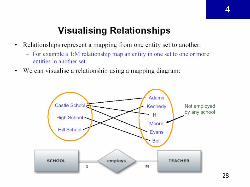
• The main characteristics of entity relationship
components
• How relationships between entities are defined and
refined and how those relationships are incorporated
into the database design process
• How ERD components affect database design and
implementation
• That real-world database design often requires the
reconciliation of conflicting goals
4
3
Data Modeling Using the
Entity-Relationship (ER) Model
• Entity-Relationship (ER) model
– Popular high-level conceptual data model
• ER diagrams
– Diagrammatic notation associated with the ER
model
• Unified Modeling Language (UML)

4
4
Using High-Level Conceptual Data Models
for Database Design
• Requirements collection and analysis
– Database designers interview prospective
database users to understand and document
data requirements
– Result: data requirements
– Functional requirements of the application: These consist of the userdefined operations (or transactions) that will be applied to
the database, including both retrievals and updates
4
5
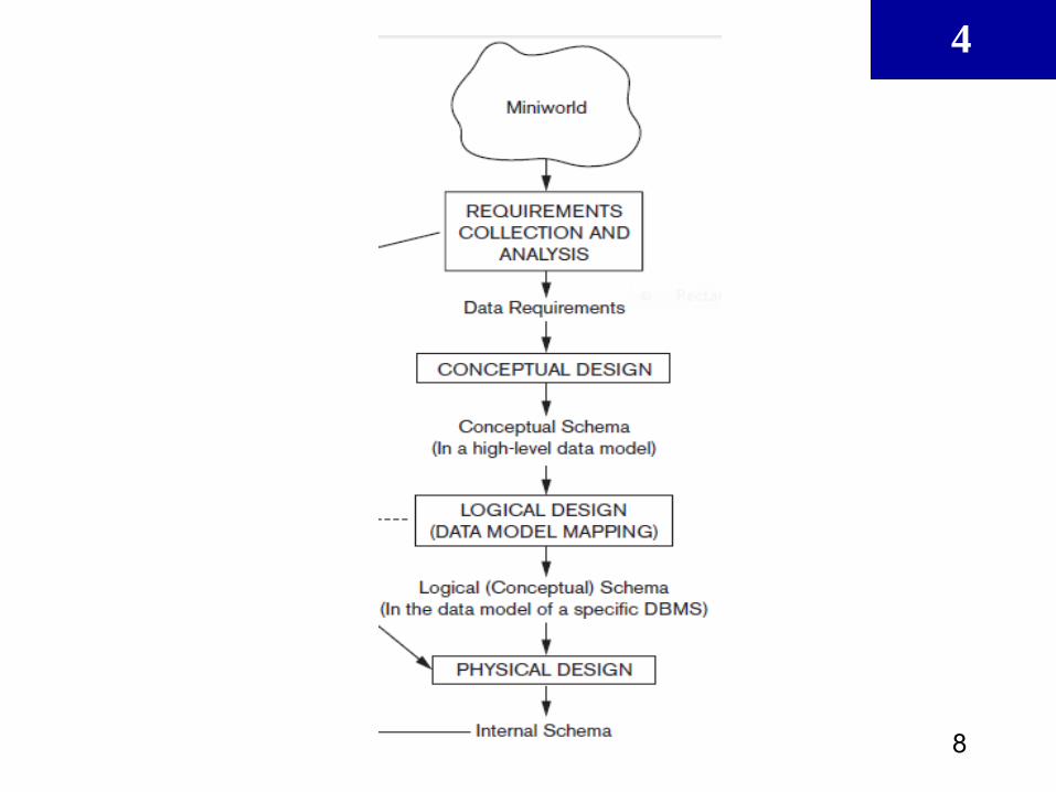
Database design methodology has 3
main phases:
1. Conceptual database design
2. Logical database design
3. Physical database design

4
6
Using High-Level Conceptual Data
Models (cont’d.)
• Conceptual schema
– Conceptual design (ER Diagram)
– Description of data requirements
– Includes detailed descriptions of the entity
types, relationships, and constraints
– Transformed from high-level data model into
implementation data model
4
7
Using High-Level Conceptual Data
Models (cont’d.)
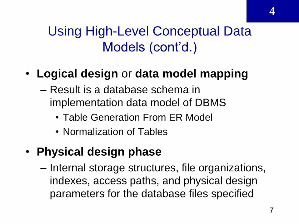
• Logical design or data model mapping
– Result is a database schema in
implementation data model of DBMS
• Table Generation From ER Model
• Normalization of Tables
• Physical design phase
– Internal storage structures, file organizations,
indexes, access paths, and physical design
parameters for the database files specified
4
8

4
9
The Entity Relationship (ER) Model
• ER model forms the basis of an ER diagram
• ERD represents conceptual database as
viewed by end user
• ERDs depict database’s main components:
– Entities
– Attributes
– Relationships

4
10
Entities
• Refers to entity set and not to single entity
occurrence
• Corresponds to table and not to row in relational
environment
• In both Chen and Crow’s Foot models, entity is
represented by rectangle containing entity’s
name
• Entity name, a noun, is usually written in capital
letters
4
11
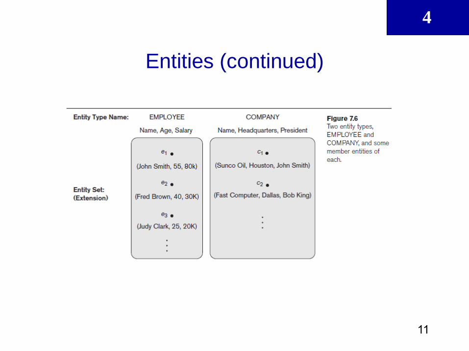
Entities (continued)
4
12
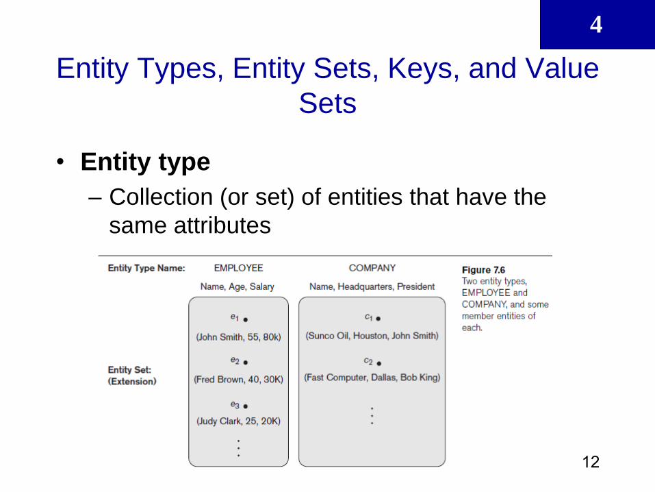
Entity Types, Entity Sets, Keys, and Value
Sets
• Entity type
– Collection (or set) of entities that have the
same attributes
4
13
Entity Types, Entity Sets, Keys, and Value
Sets (cont’d.)
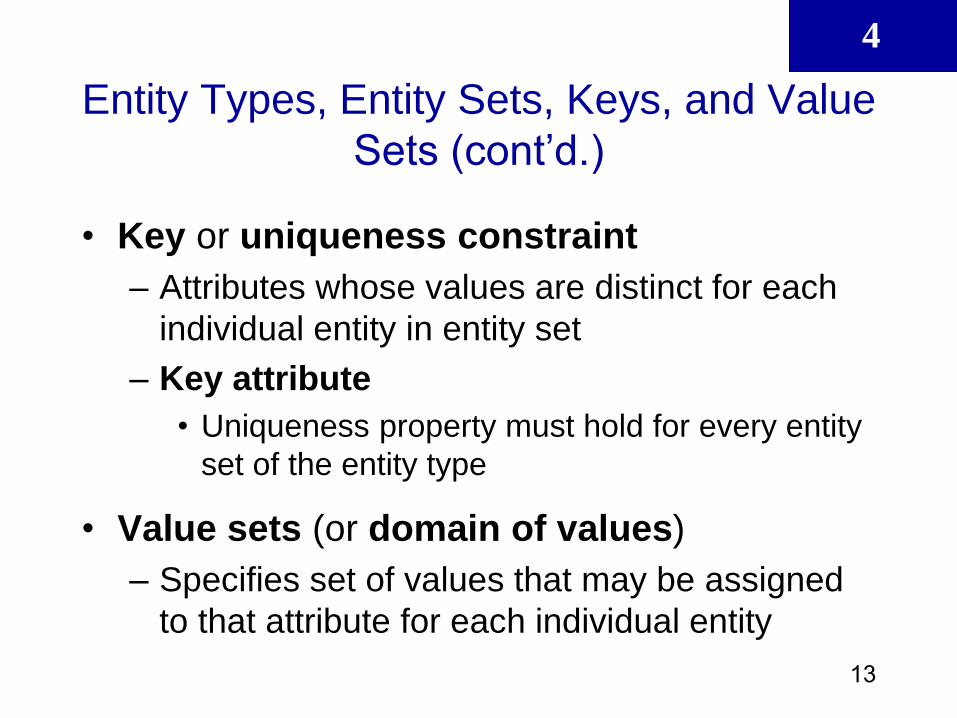
• Key or uniqueness constraint
– Attributes whose values are distinct for each
individual entity in entity set
– Key attribute
• Uniqueness property must hold for every entity
set of the entity type
• Value sets (or domain of values)
– Specifies set of values that may be assigned
to that attribute for each individual entity
4
14
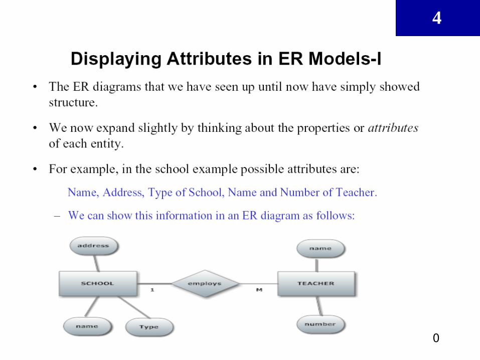
Attributes
• Characteristics of entities
• In Chen model, attributes are represented by
ovals and are connected to entity rectangle with
a line
• Each oval contains the name of attribute it
represents
• In Crow’s Foot model, attributes are written in
attribute box below entity rectangle
4
15
Attributes (continued)
• Type of attributes: − Simple (atomic) attributes
− Composite attributes
− Multivalued attributes
− Derived attributes
− NULL values
− Complex attributes
4
16
Attributes (continued)

4
17
Attributes (continued)

4
18
Identifiers (Primary Keys)
• Underlined in the ERD
• Key attributes are also underlined in
frequently used table structure shorthand
4
19
Relationships
• Association between entities
• Participants are entities that participate in a
relationship
• Relationships between entities always operate in
both directions
• Relationship can be classified as 1:M
• Relationship classification is difficult to establish if
know only one side of the relationship
4
20
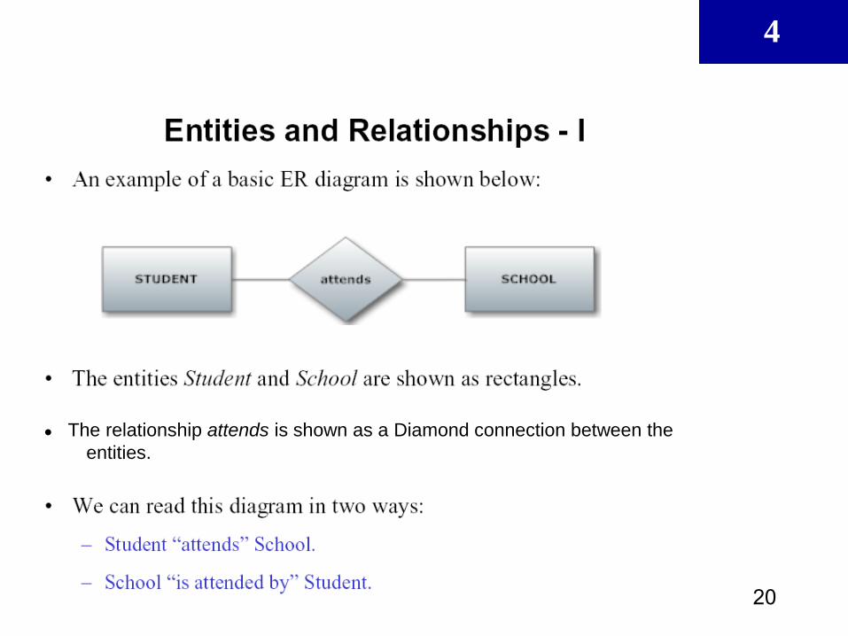
● The relationship attends is shown as a Diamond connection between the
entities.
4
21
4
22
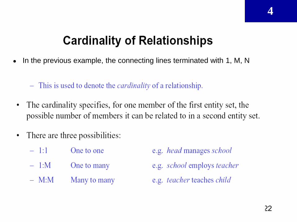
● In the previous example, the connecting lines terminated with 1, M, N

4
23
4
24
4
25
4
26
4
27
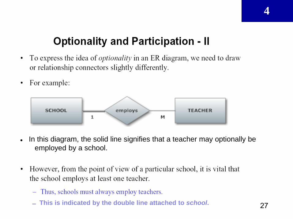
● In this diagram, the solid line signifies that a teacher may optionally be
employed by a school.
▬ This is indicated by the double line attached to school.
4
28

4
29
Constraints on Binary Relationship
Types (Cont.)
Participation constraint
Specifies whether existence of entity depends on
its being related to another entity
Types: total and partial
Partial participation: only some members of the entity
set are required to participate in a particular
relationship in which that entity type is involved.
Total participation: this happens when every entity of
the entity set participates in a particular relationship.
Total participation is also called existence
dependency
4
30
4
31
4
32
4
33
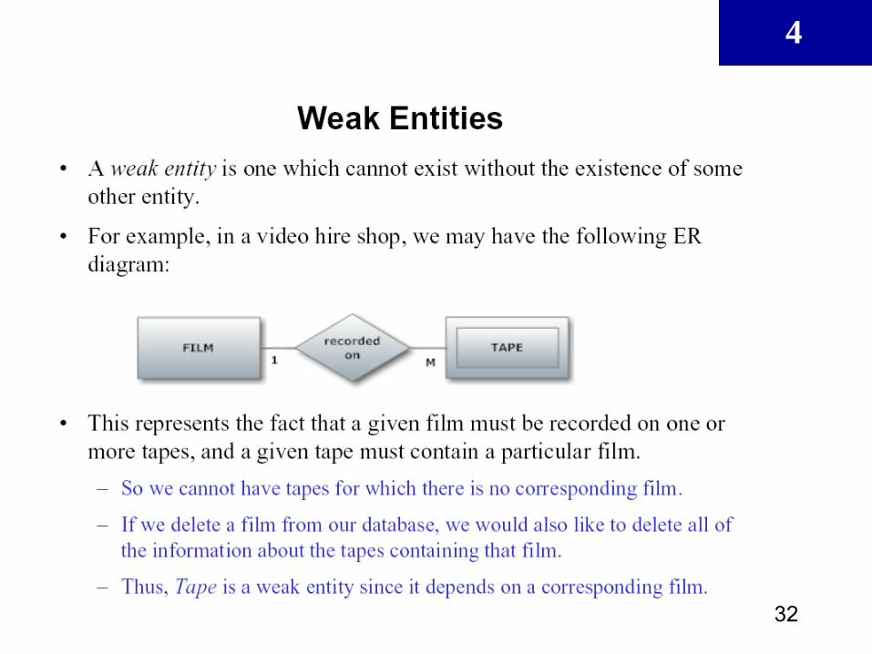
Weak Entities
• Weak entity meets two conditions
– Existence-dependent
• Cannot exist without entity with which it has a
relationship
– Has primary key that is partially or totally derived
from parent entity in relationship
• Database designer usually determines whether
an entity can be described as weak based on
business rules
4
34
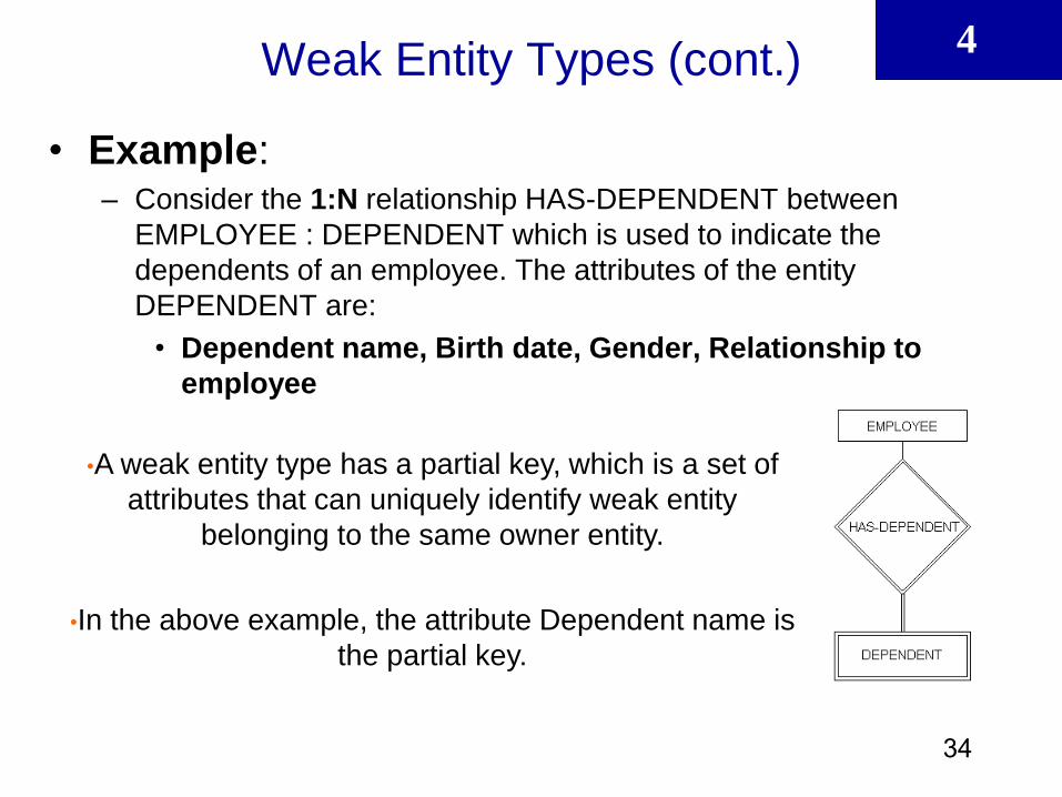
Weak Entity Types (cont.)
• Example: – Consider the 1:N relationship HAS-DEPENDENT between
EMPLOYEE : DEPENDENT which is used to indicate the
dependents of an employee. The attributes of the entity
DEPENDENT are:
• Dependent name, Birth date, Gender, Relationship to
employee
•A weak entity type has a partial key, which is a set of
attributes that can uniquely identify weak entity
belonging to the same owner entity.
•In the above example, the attribute Dependent name is
the partial key.

4
35
Weak Entities (continued)

4
36
Weak Entities (continued)

4
37
Alternative Notations for ER Diagrams
• Specify structural constraints on relationships
– Replaces cardinality ratio (1:1, 1:N, M:N) and
single/double line notation for participation
constraints
– Associate a pair of integer numbers (min, max)
with each participation of an entity type E in a
relationship type R, where 0 ≤ min ≤ max and max
≥ 1
4
38
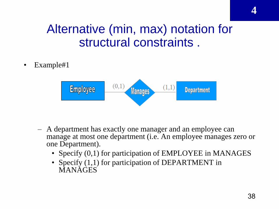
Alternative (min, max) notation for structural constraints .
• Example#1
– A department has exactly one manager and an employee can manage at most one department (i.e. An employee manages zero or one Department).
• Specify (0,1) for participation of EMPLOYEE in MANAGES
• Specify (1,1) for participation of DEPARTMENT in MANAGES

4
39
Alternative (min, max) notation for structural constraints .
• Example#2
– An employee can work for exactly one department but a department may has any number of employees (i.e. A department has zero or many Employees) • Specify (1,1) for participation of EMPLOYEE in
WORKS_FOR
• Specify (0,n) for participation of DEPARTMENT in WORKS_FOR
4
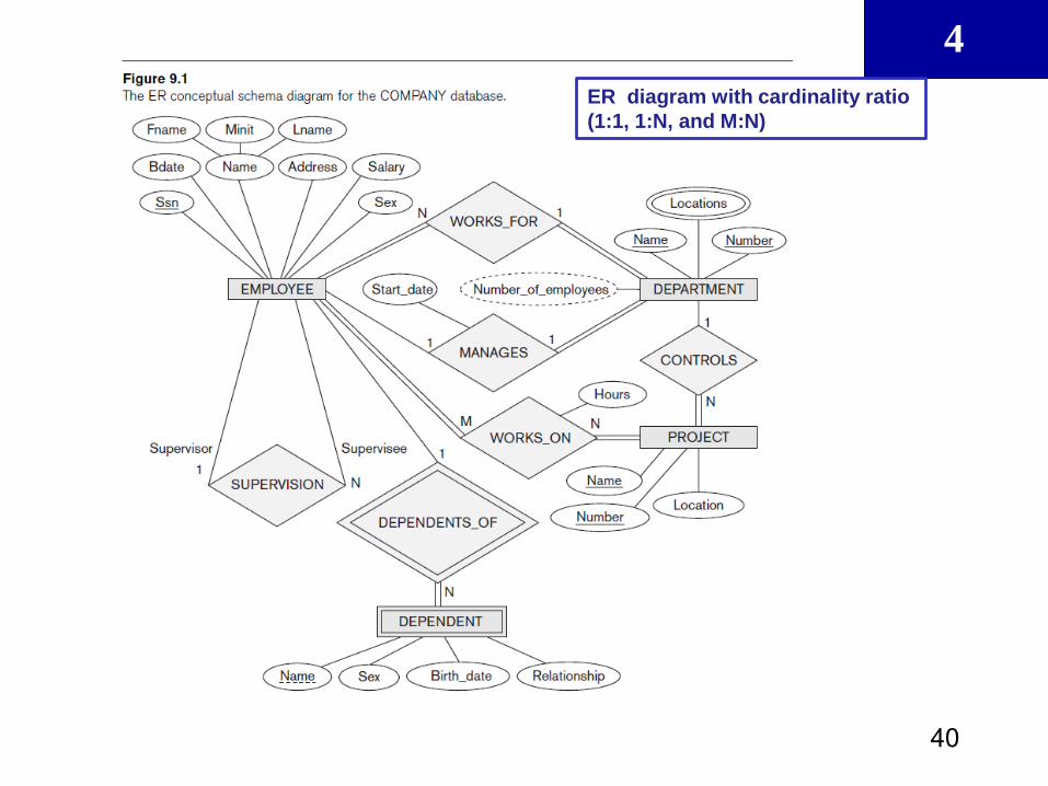
40
ER diagram with cardinality ratio
(1:1, 1:N, and M:N)

4
41
4
42
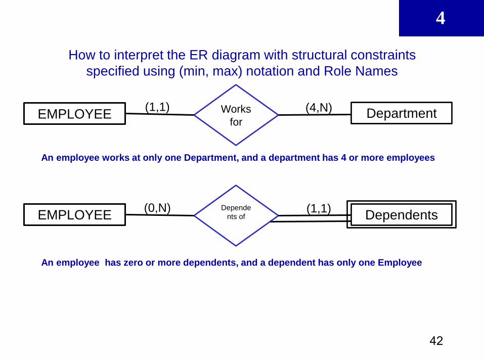
How to interpret the ER diagram with structural constraints
specified using (min, max) notation and Role Names
EMPLOYEE Department Works
for
(4,N) (1,1)
An employee works at only one Department, and a department has 4 or more employees
EMPLOYEE Dependents Depende
nts of (1,1) (0,N)
An employee has zero or more dependents, and a dependent has only one Employee
4
43
Mapping ERD into Relational Schema (Steps
with supported example illustrated in Handout5)

4
44
4
45
4
46

4
47
4
48
Developing an ER Diagram
• Database design is iterative rather than linear
or sequential process
• Iterative process
– Based on repetition of processes and
procedures

4
49
Developing an ER Diagram (continued)
• Building an ERD usually involves the following
activities:
– Create detailed narrative of organization’s description
of operations
– Identify business rules based on description of
operations
– Identify main entities and relationships from business
rules
– Develop initial ERD
– Identify attributes and primary keys that adequately
describe entities
– Revise and review ERD

4
50
Summary
• Entity relationship (ER) model
– Uses ERD to represent conceptual database
as viewed by end user
– ERM’s main components:
• Entities
• Relationships
• Attributes
– Includes connectivity and cardinality notations
4
51
Summary (continued)
• Connectivities and cardinalities are based on
business rules
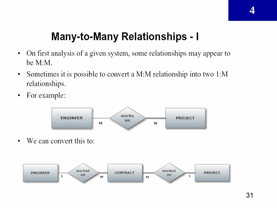
• In ERM, M:N relationship is valid at
conceptual level
• ERDs may be based on many different ERMs
• Database designers are often forced to make
design compromises

4
52
ER Diagrams notations (summery)