a isometer ir423
TRANSCRIPT
8/13/2019 A Isometer IR423
http://slidepdf.com/reader/full/a-isometer-ir423 1/4
72 Main catalogue part 1 – 08.2007/Insulation monitoring
1.6
A-ISOMETER® IR423 Insulation monitoring device for
mobile generators
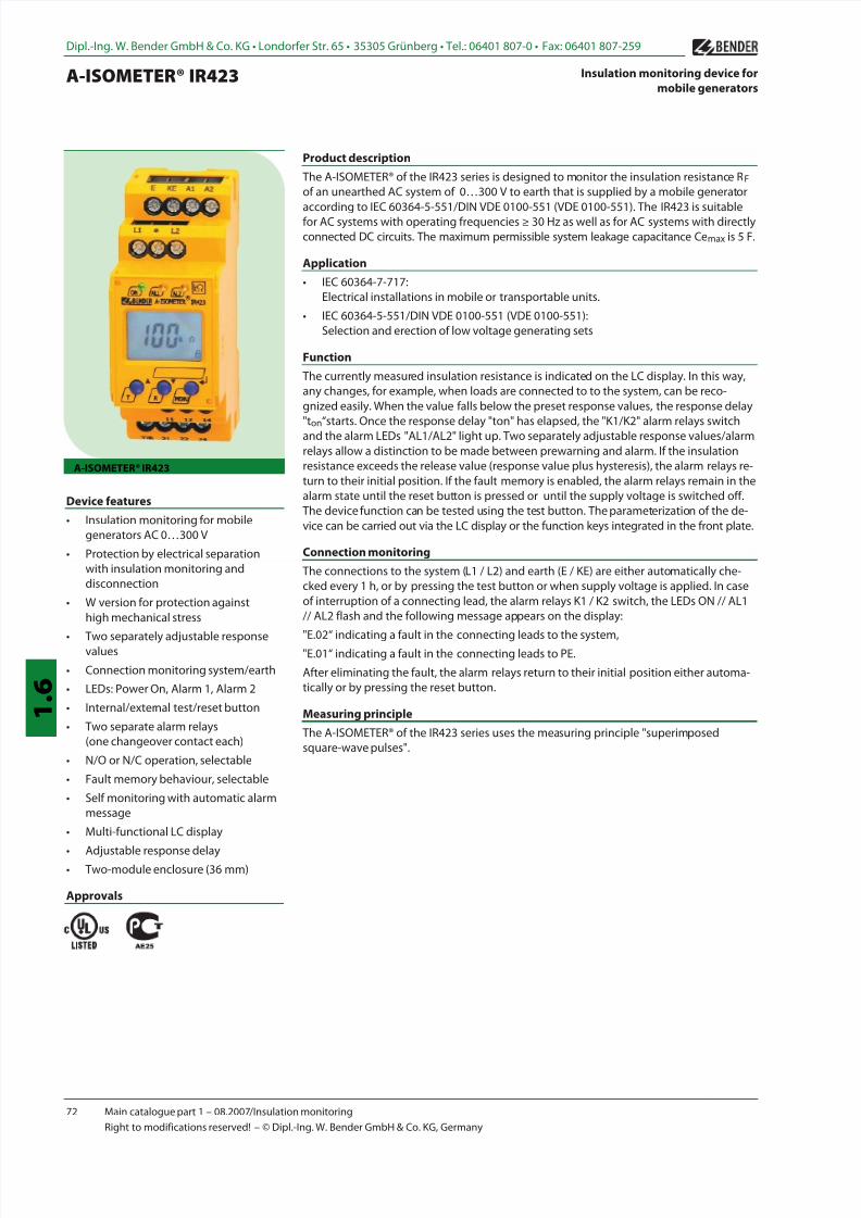
A-ISOMETER® IR423
Device features
• Insulation monitoring for mobile
generators AC 0…300 V
• Protection by electrical separation
with insulation monitoring and
disconnection
• W version for protection againsthigh mechanical stress
• Two separately adjustable response
values
• Connection monitoring system/earth
• LEDs: Power On, Alarm 1, Alarm 2
• Internal/external test/reset button
• Two separate alarm relays
(one changeover contact each)
• N/O or N/C operation, selectable
• Fault memory behaviour, selectable
• Self monitoring with automatic alarm
message
• Multi-functional LC display
• Adjustable response delay
• Two-module enclosure (36 mm)
Approvals
Product description
The A-ISOMETER® of the IR423 series is designed to monitor the insulation resistance RF
of an unearthed AC system of 0…300 V to earth that is supplied by a mobile generator
according to IEC 60364-5-551/DIN VDE 0100-551 (VDE 0100-551). The IR423 is suitablefor AC systems with operating frequencies ≥ 30 Hz as well as for AC systems with directly
connected DC circuits. The maximum permissible system leakage capacitance Cemax is 5 F.
Application
• IEC 60364-7-717:
Electrical installations in mobile or transportable units.
• IEC 60364-5-551/DIN VDE 0100-551 (VDE 0100-551):
Selection and erection of low voltage generating sets
Function
The currently measured insulation resistance is indicated on the LC display. In this way,
any changes, for example, when loads are connected to to the system, can be reco-
gnized easily. When the value falls below the preset response values, the response delay"ton“starts. Once the response delay "ton" has elapsed, the "K1/K2" alarm relays switch
and the alarm LEDs "AL1/AL2" light up. Two separately adjustable response values/alarm
relays allow a distinction to be made between prewarning and alarm. If the insulation
resistance exceeds the release value (response value plus hysteresis), the alarm relays re-
turn to their initial position. If the fault memory is enabled, the alarm relays remain in the
alarm state until the reset button is pressed or until the supply voltage is switched off.
The device function can be tested using the test button. The parameterization of the de-
vice can be carried out via the LC display or the function keys integrated in the front plate.
Connection monitoring
The connections to the system (L1 / L2) and earth (E / KE) are either automatically che-
cked every 1 h, or by pressing the test button or when supply voltage is applied. In case
of interruption of a connecting lead, the alarm relays K1 / K2 switch, the LEDs ON // AL1 // AL2 flash and the following message appears on the display:
"E.02“ indicating a fault in the connecting leads to the system,
"E.01“ indicating a fault in the connecting leads to PE.
After eliminating the fault, the alarm relays return to their initial position either automa-
tically or by pressing the reset button.
Measuring principle
The A-ISOMETER® of the IR423 series uses the measuring principle "superimposed
square-wave pulses".
Dipl.-Ing. W. Bender GmbH & Co. KG • Londorfer Str. 65 • 35305 Grünberg • Tel.: 06401 807-0 • Fax: 06401 807-259
Right to modifications reserved! – © Dipl.-Ing. W. Bender GmbH & Co. KG, Germany
8/13/2019 A Isometer IR423
http://slidepdf.com/reader/full/a-isometer-ir423 2/4
Main catalogue part 1 – 08.2007/Insulation monitoring 73
1 . 6
A-ISOMETER® IR423
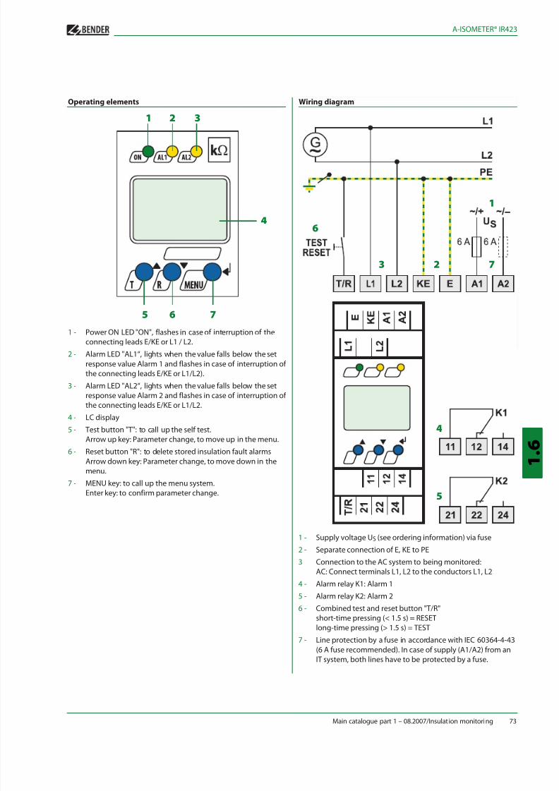
Operating elements Wiring diagram
1 - Power ON LED "ON", flashes in case of interruption of the
connecting leads E/KE or L1 / L2.
2 - Alarm LED "AL1“, lights when the value falls below the set
response value Alarm 1 and flashes in case of interruption of
the connecting leads E/KE or L1/L2).
3 - Alarm LED "AL2“, lights when the value falls below the set
response value Alarm 2 and flashes in case of interruption ofthe connecting leads E/KE or L1/L2.
4 - LC display
5 - Test button "T": to call up the self test.
Arrow up key: Parameter change, to move up in the menu.
6 - Reset button "R": to delete stored insulation fault alarms
Arrow down key: Parameter change, to move down in the
menu.
7 - MENU key: to call up the menu system.
Enter key: to confirm parameter change.
1 - Supply voltage US (see ordering information) via fuse
2 - Separate connection of E, KE to PE
3 Connection to the AC system to being monitored:
AC: Connect terminals L1, L2 to the conductors L1, L2
4 - Alarm relay K1: Alarm 1
5 - Alarm relay K2: Alarm 2
6 - Combined test and reset button "T/R"
short-time pressing (< 1.5 s) = RESET
long-time pressing (> 1.5 s) = TEST
7 - Line protection by a fuse in accordance with IEC 60364-4-43
(6 A fuse recommended). In case of supply (A1/A2) from an
IT system, both lines have to be protected by a fuse.
1
1
2 7
4
5
3
6
2 3
4
5 6 7
8/13/2019 A Isometer IR423
http://slidepdf.com/reader/full/a-isometer-ir423 3/4
74 Main catalogue part 1 – 08.2007/Insulation monitoring
1.6
A-ISOMETER® IR423
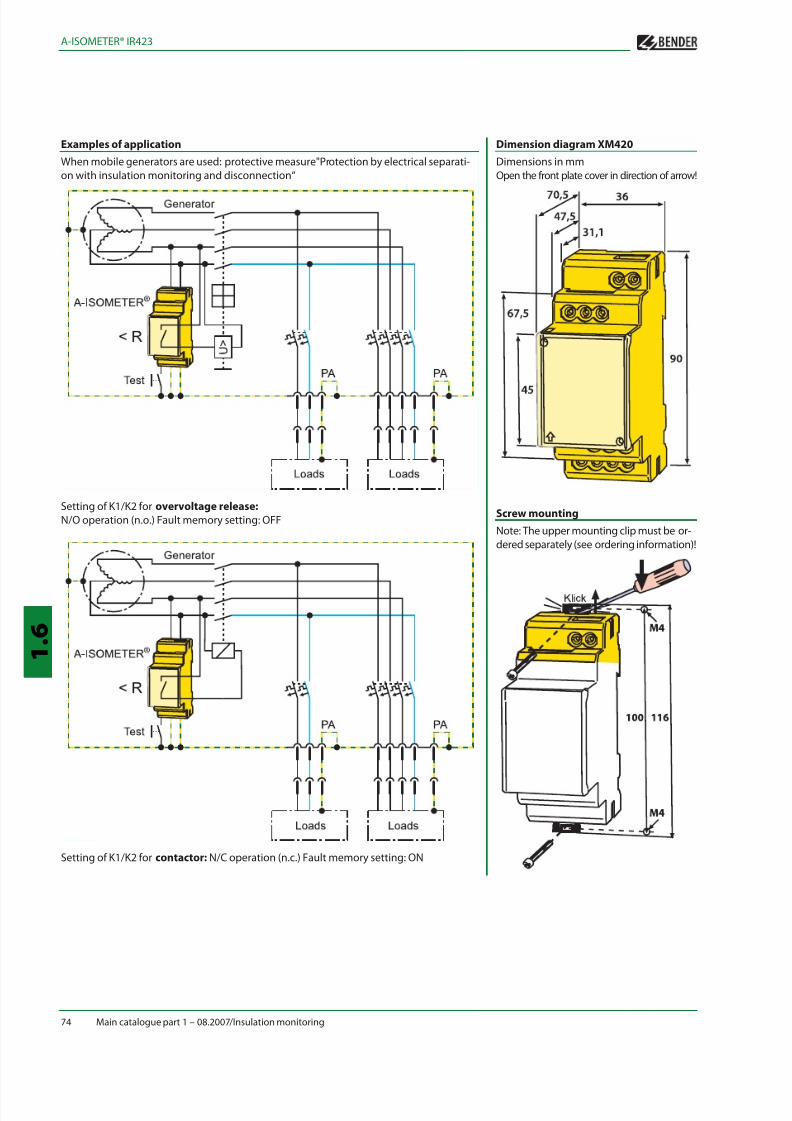
Examples of application
When mobile generators are used: protective measure"Protection by electrical separati-
on with insulation monitoring and disconnection“
Setting of K1/K2 for overvoltage release:
N/O operation (n.o.) Fault memory setting: OFF
Setting of K1/K2 for contactor: N/C operation (n.c.) Fault memory setting: ON
Dimension diagram XM420
Dimensions in mm
Open the front plate cover in direction of arrow!
Screw mounting
Note: The upper mounting clip must be or-
dered separately (see ordering information)!
8/13/2019 A Isometer IR423
http://slidepdf.com/reader/full/a-isometer-ir423 4/4
Main catalogue part 1 – 08.2007/Insulation monitoring 75
1 . 6
A-ISOMETER® IR423
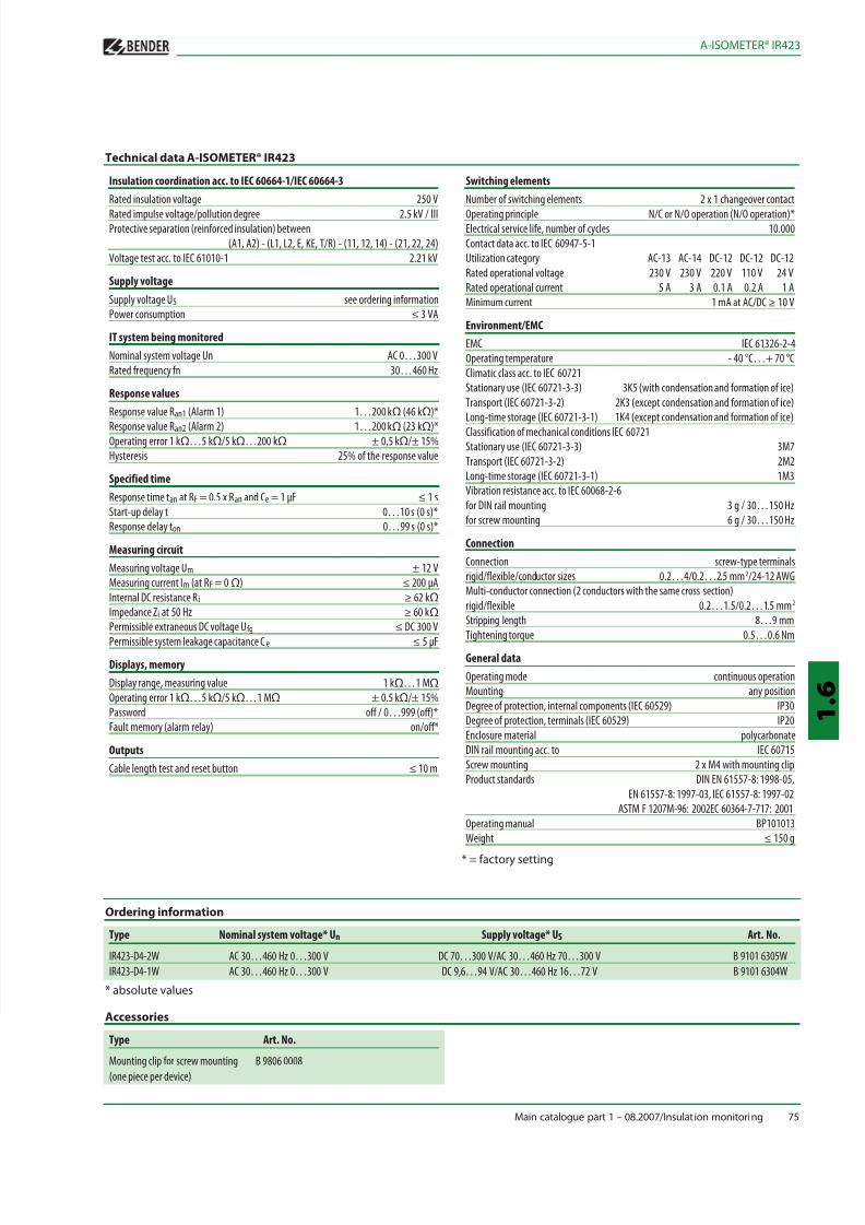
Technical data A-ISOMETER® IR423
Insulation coordination acc. to IEC 60664-1/IEC 60664-3
Rated insulation voltage 250 VRated impulse voltage/pollution degree 2.5 kV / III
Protective separation (reinforced insulation) between
(A1, A2) - (L1, L2, E, KE, T/R) - (11, 12, 14) - (21, 22, 24)
Voltage test acc. to IEC 61010-1 2.21 kV
Supply voltage
Supply voltage US see ordering information
Power consumption ≤ 3 VA
IT system being monitored
Nominal system voltage Un AC 0…300 V
Rated frequency fn 30…460 Hz
Response values
Response value Ran1 (Alarm 1) 1…200 kΩ (46 kΩ)*
Response value Ran2 (Alarm 2) 1…200 kΩ (23 kΩ)*
Operating error 1 kΩ…5 kΩ/5 kΩ…200 kΩ ± 0,5 kΩ/± 15%
Hysteresis 25% of the response value
Specified time
Response time tan at RF = 0.5 x Ran and Ce = 1 µF ≤ 1 s
Start-up delay t 0…10 s (0 s)*
Response delay ton 0…99 s (0 s)*
Measuring circuit
Measuring voltage Um ± 12 V
Measuring current Im (at RF = 0 Ω) ≤ 200 µA
Internal DC resistance Ri ≥ 62 kΩ
Impedance Zi at 50 Hz ≥ 60 kΩPermissible extraneous DC voltage Ufg ≤ DC 300 V
Permissible system leakage capacitance Ce ≤ 5 µF
Displays, memory
Display range, measuring value 1 kΩ…1 MΩOperating error 1 kΩ…5 kΩ/5 kΩ…1 MΩ ± 0.5 kΩ/± 15%
Password off / 0…999 (off)*
Fault memory (alarm relay) on/off*
Outputs
Cable length test and reset button ≤ 10 m
Ordering information
Type Nominal system voltage* Un Supply voltage* US Art. No.
IR423-D4-2W AC 30…460 Hz 0…300 V DC 70…300 V/AC 30…460 Hz 70…300 V B 9101 6305W
IR423-D4-1W AC 30…460 Hz 0…300 V DC 9,6…94 V/AC 30…460 Hz 16…72 V B 9101 6304W
* absolute values
Accessories
Type Art. No.
Mounting clip for screw mounting B 9806 0008
(one piece per device)
Switching elements
Number of switching elements 2 x 1 changeover contactOperating principle N/C or N/O operation (N/O operation)*
Electrical service life, number of cycles 10.000
Contact data acc. to IEC 60947-5-1
Utilization category AC-13 AC-14 DC-12 DC-12 DC-12
Rated operational voltage 230 V 230 V 220 V 110 V 24 V
Rated operational current 5 A 3 A 0.1 A 0.2 A 1 A
Minimum current 1 mA at AC/DC ≥ 10 V
Environment/EMC
EMC IEC 61326-2-4
Operating temperature - 40 °C…+ 70 °C
Climatic class acc. to IEC 60721
Stationary use (IEC 60721-3-3) 3K5 (with condensation and formation of ice)
Transport (IEC 60721-3-2) 2K3 (except condensation and formation of ice)Long-time storage (IEC 60721-3-1) 1K4 (except condensation and formation of ice)
Classification of mechanical conditions IEC 60721
Stationary use (IEC 60721-3-3) 3M7
Transport (IEC 60721-3-2) 2M2
Long-time storage (IEC 60721-3-1) 1M3
Vibration resistance acc. to IEC 60068-2-6
for DIN rail mounting 3 g / 30…150 Hz
for screw mounting 6 g / 30…150 Hz
Connection
Connection screw-type terminals
rigid/flexible/conductor sizes 0.2…4/0.2…2.5 mm2/24-12 AWG
Multi-conductor connection (2 conductors with the same cross section)
rigid/flexible 0.2…1.5/0.2…1.5 mm2
Stripping length 8…9 mm
Tightening torque 0.5…0.6 Nm
General data
Operating mode continuous operation
Mounting any position
Degree of protection, internal components (IEC 60529) IP30
Degree of protection, terminals (IEC 60529) IP20
Enclosure material polycarbonate
DIN rail mounting acc. to IEC 60715
Screw mounting 2 x M4 with mounting clip
Product standards DIN EN 61557-8: 1998-05,
EN 61557-8: 1997-03, IEC 61557-8: 1997-02
ASTM F 1207M-96: 2002EC 60364-7-717: 2001Operating manual BP101013
Weight ≤ 150 g
* = factory setting