a high-frequency furnace with valve generator bound... · february -1936 53 a high-frequency...
TRANSCRIPT

FEBRUARY -1936 53
A HIGH-FREQUENCY FURNACE WITH VALVE GENERATOR
Summary. An induction furnace employed in thc foundry of Philips works espec,ially formelting charges of scrap is described. -Alternnting current of high frequency is requir.edas a power supply for the furnace and is generated with the aid of a 'txansmitting valvewhich, has a useful output of 250 k\'r. ~,
To be of service to other finishing branches ofits works, Philips have for someyears been operatingtheir own melting shop and foundry, 'which forexample produces a chrome-iron alloy that can befused with glass to give a vacuum-tight joint andin vie~ of this property is employed in a largenumber of apparatus. 'O~e of the commonestfunctions of the melting shop is to melt compara-tively small quantities-of IDlI;terialunder conditionsguara~teeing 'a pre~~ribed' analyeis within' narrowlimits' of. composition. In thi~ 'work great 4ifficultyis usually experienced ~vith alloying constituentswhich; bu~n in air," such as the carbon in ferro-alloys, 'or are' ~erY' volatile, .euch ..as ii~c andcadmium in copp'er' alloys. Th~ electric arcfurnace, which was originally used for allmeltingoperafions, did not conform with the increasinglysevere requirements in' this 'diréction, since amarked volatilisation of the volatile constituerïtswas.f~und 'to occur at-'thè èiectrod~s'whóse'te~per-ature WaS about 4000 deg C. It thus becamenecessary to build a new melting furnace, whichh~d ,to ineet .the following requirements:
,1) The furnace must take a charge of 50 kg ofiron, and also enable scrap and other wastematerials to be utilised;
2) The melting charge must be kept free fromall impurities; any contact with combustiongases or electrodes was therefore undesirable.
3) To reduce the volatilisation of volatile con-stituents, tcmperatures . above the castingtemperature must he avoided as far as possible.,,For ,the same reason the melting time mustnot exceed 15 minutes.
To meet these requirements, the method of eddy-current heating was adopted, i.e. the heating ofthe melting charge by electrical eddy currents whichare produced in the c har gei t s e If by alter-nating magnetic fields. . .
In this pl'ocess the melting charge does not infact come' in contact With either comhustion gasesor electrodes. In addition, the fusing metal consti-tutes the hottest part of the furnace so that notemperatures higher than the melting temperatureoccur.The first attempts at utilising eddy current
heating for practical purposes were made some\ . _'\
30 years ago (Soc. Schneid·è'r, Creuzot and.Ó. Zander, 1905). FunaamentäÎ~theoreticaJ inves- ' ~tfgations of the induction furnaè:~·were carried oat'by No rt h r up+}, Ribe.aud2.), We~er andEiech er "), . Bu rch.. and Dá.vis4), Strut~5)and others. Details about .the ~generai b~ha~our 'of an induction furnace will" be' given below inconneenon with the ,<lesëiiptioh oCth~ Philipsmelting plant. It. has been found that the efficiencyof inductive heating in general increases with. thefrequency. The smaller the pieces making up thecharge, the. higher are the. frequencies requÏ1;.ed.If pieces of ..metal a few centimetres in diameterare to .he melted with a satisfactory efficiency,frequencies from 5000 to 10000 cycles are foundto he necessary.
A voltage of this high frequency cannothe l'eadilyand easily produced with ordinary generators. Atransmitting valve was therefore employed, viz,Philips TA 20/250 valve which on correctadaptationcan furnish a useful. output of. 250 kW (~~ vhlS14000 volts, Ielr = 18 amps). This output is .greater ,than that required for melting the chargein 15 minutes. ,j'
I) Northrup, J. Frankl. Inst. 20, 240, 1926,·
2) M. G. Riheaud, La technique moderne,'l9, No. 8-9,1929.
3) F. Wever and W. Fischcr, Inst. f. Eisenforseh. '8, 149,1926. '
,I) C.K.Burch and N.R.Davis,'Arch.f.EI.20,2U,1928.
5) M. J. O. Strutt, Ann. d. Phys. 82, 605, 1927; Arch. f,.El. 19, 424, 1928.
•J
r
54 PHILIPS TECHNICAL REVIEW VOL. 1, No. 2
Description of the Induction Furnace
The melting throughput of the plant was requiredto be 200 kg of steel per hour, for which about250 kW are drawn from the mains supply. Thefurnace plant can take a load of 300kW so thatit has an ample rating. The capacity ofthe meltingcrucible is 12.5 litres (diameter 20 cm and height40 cm) which when half charged represent 50 kgof steel. If material is added during the meltingprocess, the total charge can be increased to 100 kg.As the time taken for the settling and removal ofthe slag and for casting is roughly the same as thatrequired for melting alone, t.wo furnaces have beeninstalled which are connected alternately with thesame electrical supply. The latter is therefore inconstant service.The furnaces are so small and easy to manipulate
that no casting ladles are required. The chargesare poured directly into the moulds placed belowthe furnaces. In this way operations are continuousand l'egular, while with larger furnace charges thecasting metal, after requiring a longer period formelting, must be distributed through one or moreintermediate ladles to the variou mould and infact with great speed, as otherwise the melt is toohot at the start or too cold at the endof casting.
t tI IB A
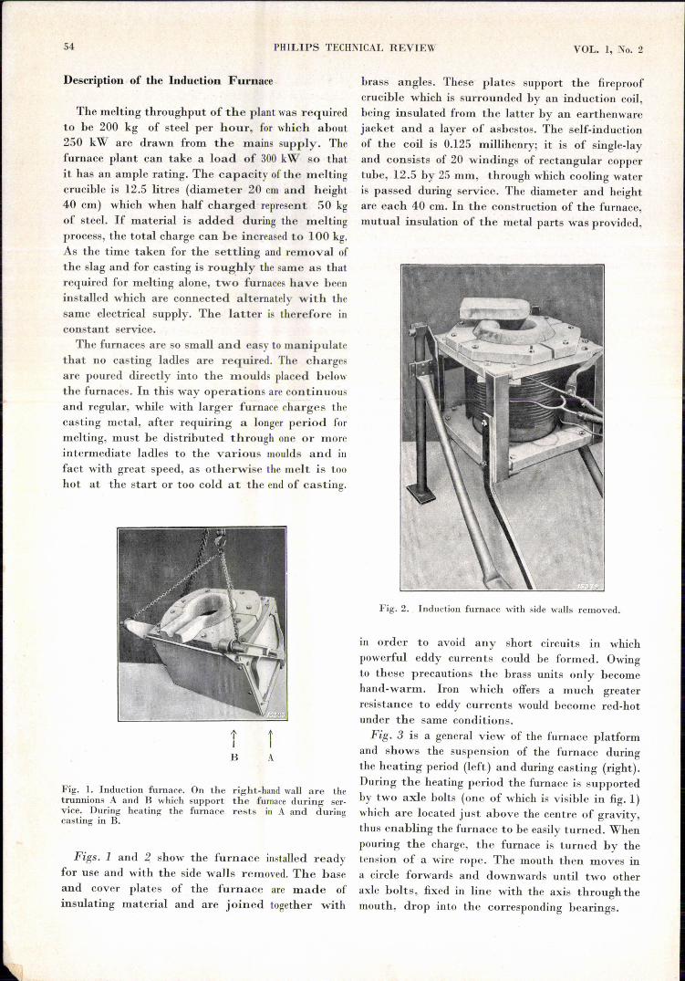
Fig. 1. Induction furnace. On the right-hand wall are thetrunnions A and B which support the furnace during ser-vice. During heating the furnace rests in A and duringcasting in B.
Figs. 1 and 2 show the furnace installed readyfor use and with the side walls removed. The baseand cover plates of the furnace are made ofinsulating material and are joined together with
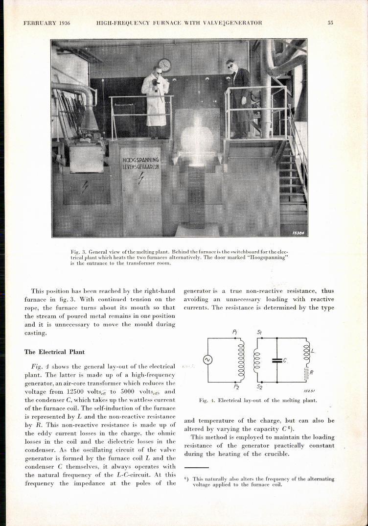
brass angles. These plates support the fireproofcrucible which is surrounded by an induction coil,being insulated from the latter by an earthenwarejacket and a layer of asbestos. The self-inductionof the coil is 0.125 millihenry; it is of single-layand consists of 20 windings of rectangular coppertube, 12.5 by 25 mm, through which cooling wateris passed during service. The diameter and heightare each 40 cm. In the construction of the furnace,mutual insulation of the metal parts was provided,
Fig. 2. Induction furnace with side walls removed.
III order to avoid any short circuits in whichpowerful eddy currents could be formed. Owingto these precautions the brass units only becomehand-warm. Iron which offers a much greaterresistance to eddy currents would become red-hotunder the same conditions.Fig. 3 is a general view of the furnace platform
and shows the suspension of the furnace duringthe heating period (left) and during casting (right).During the heating period the furnace is supportedby two axle bolts (one of which is visible in fig. 1)which are located just above the centre of gravity,thus enabling the furnace to be easily turned. Whenpouring the charge, the furnace is turned by thetension of a wire rope. The mouth then moves ina circle forwards and downwards until two otheraxle bolts, fixed in line with the axis through themouth, drop into the corresponding bearings.
FEBRUARY 1936 HIGH-FREQUENCY FURNACE WITH VALVE1GENERATOR 55
Fig. 3. General view ofthe melting plant. Behind the furnace is the switchboard for the elec-trical plant which heats the two furnaces alternatively. The door marked "Hoogspanning"is the entrance to the transformer room.
This position has been reached by the right-handfurnace in fig. 3. With continued tension on therope, the furnace turns about its mouth so thatthe stream of poured metal remains in one positionand it is unnecessary to move the mould duringcasting.
The Electrical Plant
Fig. 4 shows the general lay-out of the electrical,,'plant. The latter is made up of a high-frequencygenerator, an air-core transformer which reduces thevoltage from 12500 voltscff to 5000 voltscff' andthe condenser C,which takes up the wattless currentof the furnace coil. The self-induction of the furnaceis represented by L and the non-reactive resistanceby R. This non-reactive resistance is made up ofthe eddy current losses in the charge, the ohmiclosses in the coil and the dielectric losses in thecondenser. As the oscillating circuit of the valvegenerator is formed by the furnace coil L and thecon.denser C themselves, it always operates withthe natural frequency of the L-C-circuit. At thisfrequency the impedance at the poles of the
generator is a true non-reactive resistance, thusavoiding an unnecessal'y loading with reactivecurrents, The resistance is determined by the type
5,
c
/525/
Fig. 4. Electrical lay-out of the melting plant.
and temperature of the charge, but can also bealtered by varying the capacity C 6).This method is employed to maintain the loading
resistance of the generator practically constantduring the heating of the crucible.
6) This naturally also alters the frequency of the alternatingvoltage applied to the furnace coil.

56 PHILJPS TECHNICAL REVIEW VOL. 1, No. 2
Owing to the variahility of the loading resistance,the transmrttrng valve constitutes a markedadvance over the mechanical generator. To derivethe full output from a current generator the loadingresistance must have a dcfinite value. With amechanical generator, however, the loading resist-ance cannot be varied in the manner describedabove because the frequency is generally fixed. Itwould therefore be necessary to alter the capacityC and the self-induction L simultaneously in sucha way that the natural frequency
of the oscillating circuit maintains exactly the samevalue as the frequency of the mechanical generator.
Fig. 3 shows the switchboard of the transmitting-valve plant located at the rear of the platform.The door marked "Hoogspanning" is the entranceto the transformer room which also accomodatesa large battery of condensers. Fig. 5 shows a viewof this room as seen from the door, while fig. 6shows half of the condeneer battery. This batteryis made up of 72 separate condensers, each of
Fig. 5. 'I'ransfurrner of high-frequency furnace. Primarywinding (outside) 12500 volt.s; secondary winding 5000 volts.Part of the battery of condensers may he seen on the rightband wall of the transformer room.
0.083 [LF, which can be interconnected in fourdifferent ways. In the four positions of the switchdrum, the following capacities are obtained:
0.75 fLF, 1.5 I1.F,4.5 IJ.F and 6 I1.F.
vig. 6. Half of lhc battery of condensers. The 72 condensors,each of 0.083 !.LF, are arranged in R series.
The phase difference of the condensers is given bytg ö = 0.007. In consequence of the high voltageand frequency of the current the dielectric lossesare quite considerable. The dielectric losses N ofa condenser are given hy:
N - (1)(' • V,~. tg (5
Substituting thc respective numerical values: V,.o'=5000 volts, C = 6 IJ.F and L = 0.09 millihenry,one obt ains as a maximum value of the losses
N = 45 kW.
Table J collates the principal data relating tothe high-frf'quency furnace.
Taille I. Operating data, relating to the higb-frequency furnace.
Capacity of condenser C Frequency of alternatingcurrent
0.75 [l.F
1.5 [l.li
4.5 [.LF
6.0 [J.F
16300 to 18G(10 cycles11600 to 12800 cycles6700 10 7400 cycles5800 to 64·00 cycles
Self-induction of coil: 0.09 10 0.1.25 millihenry (depending onthe charge).
Voltage applied to fllrnace coil:Apparent powerEffective powerUseful power ill charge:
5000 voltssrrMax. 6400 kVAMax. 200 kWMax. 130 kW

F:lm:lrUARY 1936 HIGH.FREQUENCY FURNACE WITH V4VE GENERATOR
'I'he required rate of heating is readily attainedwith the furnace. With a 108s of 30 per cent as aresult of thermal conduction and radiation, about18 kW·hrs. are required for melting 50 kg of iron.4s _under the most favourable conditions of ~@ii§ about 130 kW are furnished to the charge,the', timè required for melting is- found to be 8.3minutes. The actual time taken is of course
"
longer, hut even with the Îhost'difficult charge inthè crucible only 10 to '15 minutes' are -required.
In the case of metals with a higher conductivitythan i~o~;the proportion ofthe total power,s~pplie~.which is absorbed by the charge is naturally smaller.Nevertheless aluminium, silver and copper can' alsobe melted in this high-frequency furnace. At a' firstglance this appears surprising, .eince for instance acharge of copper shavings can in no case be heatedtO'8:higher ternperature than the copper inductioncoil itself, if the diameter of the shavings is not grea.ter than that of the copper tube of which the coil ismade. 'This shows quite clearly that water coolingis imperative. Cooling keeps the resistance of theinduction coil low, while the resistance of thecharge rises as a result of heating to about 4 timesits initial value.
Discussion of the Method of Operation of the High-. Frequency Furnace
,~
Omitting all consideratiou of the processes inthe high-frequency furnace itself, we can regard itas a loading impedance with an inductance Landa 'resistance R. For the plant in question we thusobtained the diagram shown in fig. 4. At theresonance frequency, the secondary terminals SIand S2' 0.£ the transformer are loaded with a non-reactive resistance W, which in the case of asufficiently small damping resistance R 7) of theoscillating circuit, is given approximately by:
, LW= CR'
As already pointed out, the commutable capacity Cis so adjusted that the resistance W approaches asclose as possible to a specific optimum value Ws.In this case Ws is 127 ohms. The resistance acrossthe primary terminals of the transformer is thenWp _Ws times squared transformation ratio = '127 X 6.25 ' 720 ohms.". It i~s thus equal to' the internal resistance ofthe tranSmitting valve. '
, 27) "Small damping" signifies Rr: « 1.
A somewhat closer insight into the pl'oce~s ofheat evolution' in the furnace is obtained byregarding the furnace coil as the primary windingof a transformer whose secondary winding con-stitutes the path of the current in the charge. Thisis shown in the diagram infig. 7 where the indices 1
, ,
Rf M
IS254
Fig. 7. Substitution diagram for high-frequency furna~ti:1~1and RI are the self-induction and resistance of the furnuèecoil. L2 and R2 are thc self-induction and resistance of thecharge. The mutual induction is represented by M.
relate to the furnace coil and the indices 2 to thccurrent path through the charge.
Owing to the mutual inductance M the resistanceof the charge is imparted to the primary coil. III
. order to obtain a satisfactory efficiency, this resist-ance RK which is coupled to the inp!lt'side mustbe '~s large as possible ~i>mparèd, with ,t~é 'inputresista~cc Rl' Thc power tinput is.,' 0 ,<~;,',
. . ~~;\~.':'. ,.,~'.~ .N = 1;11' (/{1 + RK)
and the efficiency.: .
'/
If' Ql is the frequency of the alternating currentexpressed in circular measure, one "obtains by asimple, cl!-l?ulation
. (f)
Equation' (1) is derived from the tran~,t'orme~equations:
'1 (Hl + i Ol 1.1) + '2 i cu M' = UI
'1 i '" ivi+ /a (i ,,; 1.2 + R2) = 0,.... "' __ ". '. '.- -.which express the relationship between the' primary voltageUI and the primary andsecondary currents '1 and 12,. Elimi·nating 12 from these equations; one: obtains:. .
The tlÎird and fourth terms in this expression give the additionalresistance RK and a corresponding (negative), additionalinductance. '
. .
l
57
-, '
. ,
.-,_".
" ,
/

"
\
58 " PHILTPS TECHl'jICAL REVIEW " VOL. :j., No. 2
, The variation of RK with respect to w is shownin fig.8. This' diagram shows (RK/R2). (L22/M2)plotted against (wL2/ R2) • "
It is' seen from the curve that RK at first risesquicklywith the frequency, eventually to becomeasymptotic to the limiting value: RK ~ R2 M21L22.
I,O~----------~~~---------------------
/.5257
Fig. 8. Couplingresistanc~ RK plotted against the frequency.W!Ien co L2/R2 = 3, RK assumes 90 per cent of its asymptoticlimiting ,value. ' ,
As already stated,. a high coupling resistance isrequired in order to obtain a satisfactory efficiency.The frequency must therefore be made so high thatthe limiting Value is almost obtained. On the other'hand, it is desirable to keep the frequency as lowas possible since at a given output the lossesexterior to the furnace as a rule increase with thefrequency. We shall therefore stipulate a couplingresistance of only 90 per' cent of the limiting value,which 'according to the graph (8) corresponds tothe condition that:
> 3
/5258
,Fig. 9. Intensity of eddy currents produced in a metal cylinderby a homogeneousmagnetic field in the direction of the axis,The arrows indicate the direction of the eddy currents. '
A further increase in the frequency (in radians)would result" in very little improvement of theefficiency,The substitution of a self-induction L2 and a resist-
ance R2 for the electrical properties of the chargeasks for a .further comment, The !listribution of
v\
the eddy currents in the charge depends on thefrequency of the magnetic field, and as 'a resultL2 and R2 also vary with the frequency., In order to visualise the distribution of the eddycurrents, consider firstly ~he limiting cases at verylow and very high frequencies, Consider a cylinderwhose axis is parallel to the magnetic field (fig.9).It is well known that the induction currents are insuch directions that within the metal they weaken themagnetic field. If the frequency is sufficiently low,the induced voltages and currents are, however, so
, small, that the weakening of the field can beneglected. In this case the distribution of currentshown in fig. 9 is obtained. The current density iszero along the axis and increases in proportion tothe radius.
The l;righer the frequency, the greater will be theweakening of the magnetic field in the interior of thecylinder. At the same time the eddy currents, inthe interior also become weaker and with rising, frequency we get in succession the current diatrihu-tion curves Il, III and IV shown in, fig. la. Inthe limiting case of a very high frequency the
I
(2)" Ism
Fig. 10. Intensity of the eddy currents produced in a cylinderat different frequencies, Owing to the natural magnetic fieldof the eddy currents, the total field 'is not homogeneous,but greater at the walls than in the' interior. Witli risingfrequency the current distribution is altered from 1 (see alsofig. 9) to ,U, ,lU and IV.
current flows merely through a thin layer at thesurface.We shall reserve the opportunity of returning
to these interesting phenomena 'in greater detailin a subsequent '~is,siieof this periodical. Closerinvestigation sho~~"'tliat the' condition wL2/ R2 >:3in 'every case leads to such a high frequency thatthe displacement of the magnetic field from theinterior of the pieces .making up the charge alreadybecomes very pronounced. The current flowsthrough a layer at the sûrface, whose tlücknessat a given frequency is, only' slightly dependenton the sizes of the piece,s. In "this case the fraction
•HIGH-FREQUENCY FURNACE WITHVALVE GENERATOR 59FJ3,:BRUARY J 936
of the self-induction value L2 due' to .a single piece. (e.g. of spherical shape) will ..increase with thevolume, while the resistance R2 will be practicallyindependent of the size of the piece. As a resultthe ratio L2/R2 will increase with the size modulus.The smaller the pieces making up the charge, thehigher therefore will be the frequency required inorder' to make wL2/R2 sufficiently large.With the frequencies of 6000 to 7000 cycles used
here, the condition wL2/R2 > 3 is still met withpieces a few centimetres' in size. In general thepolicy will be not to use the .frequencies higherthan are absolutely necessary, as' the generationof high-frequency' alternating currents with 'asatisfactory efficiency becomes progressively moredifficult as the frequency is raised (e.g. owing t~the ip.crease in the dielectric losses).
Convection Currents in the Melt
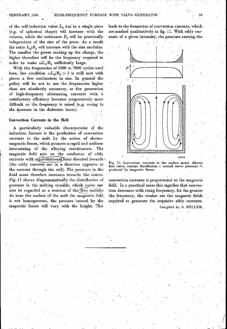
A particularly valuable characteristic of. theinduction furnace is the' production of convectioncurrents in the melt by the action of electro-magnetic forces, which promote a rapid and uniformintermixing of the 'alloying constituents. Themagnetic field acts on the conductor of eddyc~rrents with a@vitation~orce directed inwards ..(the eddy currents are in a direction opposite tothe current through the coil). The pressure, in thefluid mass therefore increases towards the centre.Fig.il.I shows diagrammatically the distribution ofpressure in the melting crucible, which curve canalso hè regarded as a contour of the@~ _su~-fa~;,As near the surface of the melt the magnetic field.is not homogeneous, the pressure' 'caused by themagnetic forces will .vary with the height. This
leads to the formation of convection currents, whichare marked qualitatively in fig. 11. With eddy cur-rents of a given intensity, the. pressure ca~s~ng the
rszeo
Fig. 11. Convection currents in the molten metal. Above:first curve, current distribution i; second curve: pressure P,produced by magnetic forces.
convection currents is proportional to the magneticfield. In a practical sense this signifies that 'convec-tion decreases with rising' frequency, for the greaterthe frequency, the weaker are the magnetic fieldsrequired to. generate the requisite eddy vcurrents.
Compiled by G. HELLER.