a high efficiency and high power chopper circuit qras
TRANSCRIPT
A High Efficiency and High Power Chopper Circuit QRAS … 1
JPE 6-1-1
A High Efficiency and High Power Chopper Circuit QRAS using Soft Switching under Test Evaluation at 8kW
Yukinori Tsuruta† and Atsuo Kawamura*
†*Yokohama National University, Yokohama, Japan
ABSTRACT
This paper is a record of the study on a high efficiency and high power chopper based on the new soft switching method QRAS (Quasi-resonant Regenerating Active Snubber) designed for a Fuel Cell Electric Vehicle (FCEV). This power chopper is basically proposed for 25kHz soft switching. To confirm the practicality and effectiveness of the converter, the fabrication of a prototype-model using IGBTs was completed. Additionally, a 8kW rating test, a light load test, a current discontinuous mode test and a stable operation resonance test was completed. The circuit geometry, the basic operation, and the 8kW one-tenth-prototype test results are reported with a 97.5% efficiency measurement.
Keywords: Boost chopper, DC-DC converter, Soft switching, QRAS, 2 switch, IGBT
1. Introduction
The recent progress of electric drives in the automobile industry has produced pure electric vehicles. Fuel cell technology makes it possible to implement a 100kW power range converter to a Fuel Cell Electric Vehicle (FCEV). In the recent middle and high power applications mentioned above, high power and high efficiency are major requirements of DC-DC converters to realize downsizing. In particular, in the case of a previous DC chopper circuit for high power applications, hard switching at low frequencies has been used because of the difficulty of high frequency operation. In other words, the size was large and the power dissipation was also large.
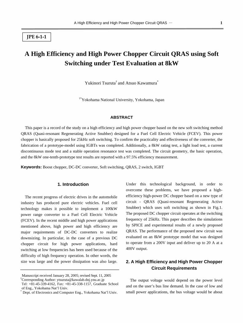
Under this technological background, in order to overcome these problems, we have proposed a high- efficiency high-power DC chopper based on a new type of circuit - QRAS (Quasi-resonant Regenerating Active Snubber) which uses soft switching as shown in Fig.1. The proposed DC chopper circuit operates at the switching frequency of 25kHz. This paper describes the simulations by SPICE and experimental results of a newly proposed QRAS. The performance of the proposed new circuit was evaluated on an 8kW prototype model that was designed to operate from a 200V input and deliver up to 20 A at a 400V output.
2. A High Efficiency and High Power Chopper
Circuit Requirements The output voltage would depend on the power level
and on the user’s bus line demand. In the case of low and small power applications, the bus voltage would be about
Manuscript received January 28, 2005; revised Sept. 11, 2005 †Corresponding Author: [email protected] Tel: +81-45-339-4162, Fax: +81-45-338-1157, Graduate School of Eng., Yokohama Nat’l Univ.
* Dept. of Electronics and Computer Eng., Yokohama Nat’l Univ.
2 Journal of Power Electronics, Vol. 6, No. 1, January 2006 100V. On the other hand, in middle and high power applications our specifications can be 400V with a 100kW power range converter. An additional point to take into account is the fuel cell module used will determine the converters’ topology. When the bus voltage is larger than the fuel cell voltage, a boost type converter is needed.
However, high voltage and high power applications mentioned above make high frequency switching and downsizing of the power converter difficult to be realized.
A practical model converter should have the following specifications: Input voltage (fuel cell bus voltage) Vi=250~400[V] Output voltage (bus voltage) VO=400[V] Switching frequency fS=25k [Hz] Output power PO=80k [W]
3. Usual Chopper Circuit
3.1 Classifications of Chopper Circuits Various types of chopper circuits have been used or
proposed until now. A classification of this typical circuit is shown in Table 1.
Type 1 : Hard switching is shown in Type 1(a). Main switch S1 cuts off the main current directly by eliminating the passive snubber from the conventional one. Main drawbacks are power dissipation and voltage overshoot. The switching power dissipation of this type is at a maximum in high frequency operations and the surge voltage depends on the wiring inductance. Type 1(b), the passive resonant snubber is added to the conventional one. The current stress on switch S1 increases due to the
resonant current of the snubber circuit superimposed on the load current when switch S1 is turned on [2].
Type 2 : Type 2(a) and Type 2(b) are one-switch resonant schemes. In type 2(a), the circuit voltage doubles due to the utilization of the resonant phenomenon of capacitor Cr and reactor Lr which are added to the main circuit. Type 2(b), this type is regarded as being difficult to obtain high efficiency. Because the resonant current flow of constant amplitude is superimposed on load current through a switch device[3].
Type 3 : This type is 2 switch partial resonant scheme. A ZVT converter [4] is shown in Type 3(a). It is said that this type can obtain high efficiency without increasing the current stress of the main switch since the current flow of the auxiliary circuit does not pass through the main switch. Its drawback is the hard switching of the auxiliary switch. Type 3(b), the auxiliary switch circuit is modified to achieve the soft switching. But the overshoot voltage by parasitic oscillating phenomenon should be suppressed[5].
Type 4 : The previous C bridge switch type soft switching chopper [6] is depicted in Type 4(a). The main part is made of 2 switches and 1 capacitor. But it was
LOAD
C0
L1 D5
E1
SL1
L2
S2 D1
D4
D3 S1
C1 Ci
Fig. 1 New type of circuit for high power dc chopper QRAS
Table 1 Various Chopper Circuits
(a) basic (b) modification (a) basic (b) modification
1
L1
S1 C0
DF
E1
RL
L1 D5
S1
C0
C2
C1
D1
L2
E1
RL
D3
D2
3
L1 D5
S1C0
S2
C1D1
L2
E1
RL
L1 D5
S1 C0
C2
C1 Lr E1
RL
D3
S2
2
L1
Lr
S1
C0
Cr
DF
E1
RL
L1 D5
C0
S2
Cr D1
Lr
E1
RL
4
L1 D5
S1 C0
S2
C1
D1
D3
E1
SL1
RL
L1 D5
S1 Cp
S2
C1 D1
D3
E1 D2
RL
CnS3 S4
D4
D6
A High Efficiency and High Power Chopper Circuit QRAS … 3
proved to be necessary to adjust the turn on timing of switch S1 and switch S2 not to superimpose the capacitor charged voltage on the overshoot voltage of the output diode during its reverse recovery. Type 4(b), this is similar to the C bridge switch Type 4(a). But this is a soft-switched voltage-doubler rectifier. Its drawback is the component count. The soft switching reduces the losses of the switches, but as the number of diodes is multiplied by two, conduction losses are increased [7].
3.2 Conventional example of the prototype
using Type 4(a) Each type of circuit scheme listed in Table 1 has merits
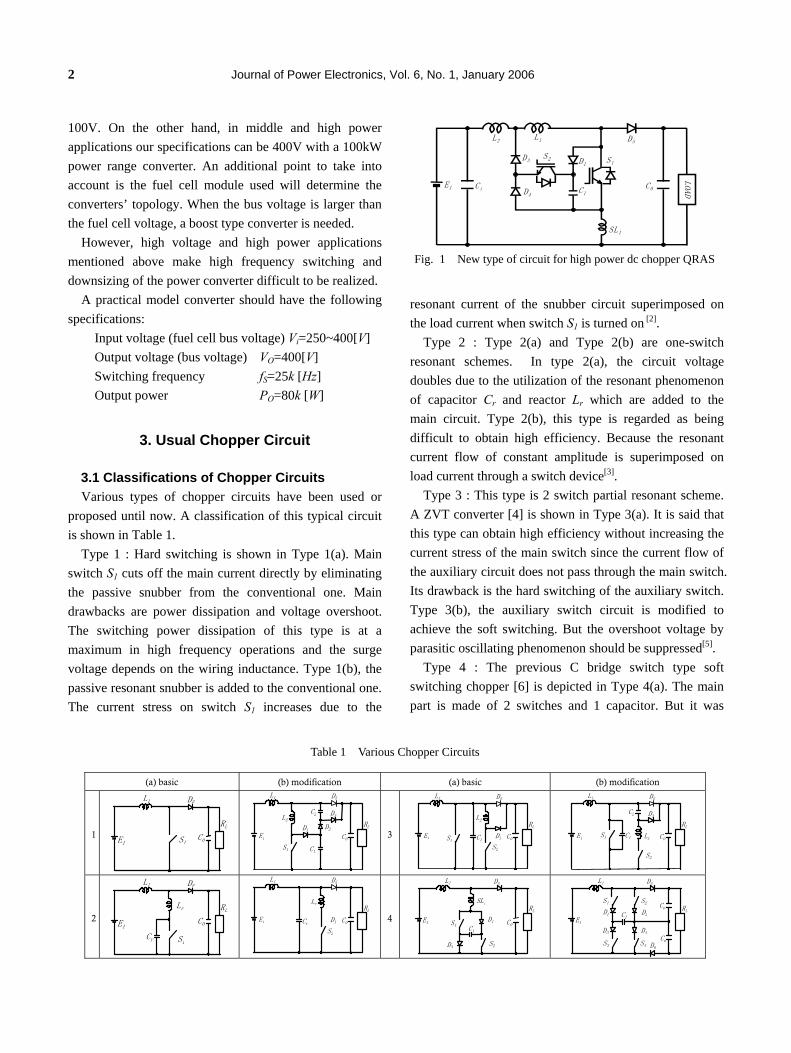
and demerits. The circuit topology should be determined depending on if one scheme or combined schemes is selectively chosen corresponding to its application's side specification and requirement. In the case of a 100kW power range converter using IGBT to the FCEV, Type 4(a) is most suitable regarding improving the efficiency of the hard switched converter, keeping the simplicity, the component number and availability of switching devices. It can operate as the promised and achieved snubber
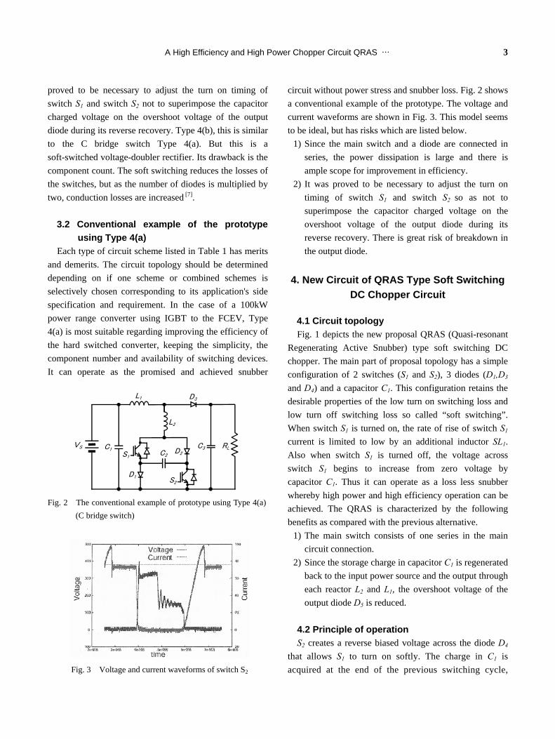
circuit without power stress and snubber loss. Fig. 2 shows a conventional example of the prototype. The voltage and current waveforms are shown in Fig. 3. This model seems to be ideal, but has risks which are listed below.
1) Since the main switch and a diode are connected in series, the power dissipation is large and there is ample scope for improvement in efficiency.
2) It was proved to be necessary to adjust the turn on timing of switch S1 and switch S2 so as not to superimpose the capacitor charged voltage on the overshoot voltage of the output diode during its reverse recovery. There is great risk of breakdown in the output diode.
4. New Circuit of QRAS Type Soft Switching
DC Chopper Circuit
4.1 Circuit topology Fig. 1 depicts the new proposal QRAS (Quasi-resonant
Regenerating Active Snubber) type soft switching DC chopper. The main part of proposal topology has a simple configuration of 2 switches (S1 and S2), 3 diodes (D1,D3
and D4) and a capacitor C1. This configuration retains the desirable properties of the low turn on switching loss and low turn off switching loss so called “soft switching”. When switch S1 is turned on, the rate of rise of switch S1 current is limited to low by an additional inductor SL1. Also when switch S1 is turned off, the voltage across switch S1 begins to increase from zero voltage by capacitor C1. Thus it can operate as a loss less snubber whereby high power and high efficiency operation can be achieved. The QRAS is characterized by the following benefits as compared with the previous alternative.
1) The main switch consists of one series in the main circuit connection.
2) Since the storage charge in capacitor C1 is regenerated back to the input power source and the output through each reactor L2 and L1, the overshoot voltage of the output diode D5 is reduced.
4.2 Principle of operation S2 creates a reverse biased voltage across the diode D4
that allows S1 to turn on softly. The charge in C1 is acquired at the end of the previous switching cycle,
VS C1
L1
L2
D3
S1
S2
C2
D1
D2
C3 RL
Fig. 2 The conventional example of prototype using Type 4(a) (C bridge switch)
Fig. 3 Voltage and current waveforms of switch S2

4 Journal of Power Electronics, Vol. 6, No. 1, January 2006
and any excess charge is returned to the supply through L1 and L2 in the early part of S1 turning on. Fig.4 shows typical voltage and current operating waveforms of the proposed new circuit, calculated using SPICE. Each operating mode is illustrated in Fig.5 and operates as follows.
(a) mode 1 : Pre-turn-on Auxiliary switch S2 is turned on before turning on the main switch S1 by a few micro-seconds for the soft turn-on of S1.
(b) mode 2 : Turn-on The main switch turns on softly and the charge in C1 is
transferred to the reactor L1 and L2. (c) mode 3 : On state with regenerating The magnetic energy in L1 and L2 transferred from C1 is regenerated to the DC input source.
(d) mode 4 : On state The reactor current is built up.
(e) mode 5 : Turn-off The snubber capacitor C1 is charged by the current flowing through D1.
(f) mode 6 : Off-state The switches are all in off-state.
5. 8kW One-tenth-model for Experiments
5.1 Prototype-model A 8kW prototype-model using IGBTs was made and is
shown in Fig. 6. The rating parameters of this prototype-model are as follows. ・Output ratings: V0=400[V], Pout=8k[W] ・Duty: D=0.5, ・Switching frequency: fS=25k[Hz]
・Circuit parameters: C1=0.33μ[F], L1=L2=100μ[H], SL1=0.6μ[H]
5.2 Experimental evaluation and discussion The principal circuit operation was verified by a rating
-t1 t0 t1 t2 t3 t4 t5
main switchS1
gate voltageVGS1
auxiliary switchS2
gate voltageVGS2
main switchS1
currentICS1
auxiliary switchS2
currentICS2
main reactorL1,L2 currentIL1,IL2
snubber capacitorC1
voltageVC1
mode1 mode2 mode3 mode4
mode5 mode6
Fig. 4 The basic operating waveforms of QRAS
Fig. 5 The six operational modes of QRAS

A High Efficiency and High Power Chopper Circuit QRAS … 5
93949596979899
0 2000 4000 6000 8000 10000
Output power[W]
Eff
icie
ncy[
%]
efficiency(measured)efficiency(SPICE)
Fig. 8 The efficiency(measured) and efficiency(SPICE) vs. output power
test, light load test, current discontinuous mode test and test stable operational resonance. The soft switching by the proposed circuit is proved to be achieved. The experimental results from the prototype model tests are shown in Figures 7 to 10.
1) The evaluation of the circuitry operational verification
Fig. 7 shows the results of the measurement coincides with SPICE. The waveforms were measured by means of a WAVEPRO950 Lecroy digital oscilloscope. From these
results, it is verified that the experimental results nearly corresponds to the simulation results. The normal operation of the prototype QRAS was confirmed.
2) The efficiency measurement The prototype QRAS was tested and efficiency was
measured every ∆Pout=1k[W] step until the rating condition of E1=200[V], V0=400[V], Pout=8k[W]. We measured 4 times under the same conditions allowing for reading error of the meters. Fig. 8 plots the average of the measurements mentioned above. Total efficiency was measured by means of VOAC7413 Iwatsu digital multi-meters, 2011 Yokogawa DC Ammeters and 2215 Yokogawa shunts. The efficiency measured shows the results that are nearly coincides with SPICE. The output power of 8kW with the efficiency of about 97.5% was obtained under the frequency of 25kHz and 50% duty ratio.
3) The discontinuous current mode test Next we tested the discontinuous mode condition under
the specifications of the load resistance RL=480[Ω]. Fig. 9 shows the current discontinuous mode. The current of reactor L1 decreases and touches zero. From this result, it was verified that the prototype QRAS operated normally.
4) Test of resonance stable operation We define the stable operational resonance region as the
duty control area where the prototype QRAS operates in the soft switching. We tested out of this region. Fig. 10 shows the typical waveforms in this mode when duty D=0.11. It is clear that the charge in C1 is not discharged perfectly to zero. So the main switch S1 and the auxiliary switch S2 cannot be turned off from zero voltage. Thus
Common capacitorC1
Auxiliary switch S2 Reactor SL1
Main reactor L2,L1
Main switch S1
Fig. 6 Exterior of 8kW prototype model QRAS
0
20
40
60 [A]
IC
VCE
IL1
IL2
(a) The main switch S1 voltage and current
(b) The auxiliary switch S2 voltage and current
(c) The main reactor L1,L2 current
VCEIC
0
300
100
200
[V]
VCEIC
0
300
100
200
[V]
0
20
40
60 [A]
IC
VCE
0
10
20
30 [A]
5μs/DIV
IL1
IL2
Fig. 7 The verification of the operational waveform (the comparison between SPICE and measurement)

6 Journal of Power Electronics, Vol. 6, No. 1, January 2006
they are turned off by hard switching. However, we confirmed that duty D was able to reduce perfectly to zero in spite of the hard switching.
Considering the test evaluation mentioned above, it was proved that the proposed QRAS could operate with high performance in comparison to the conventional one.
6. Applying QRAS Scheme to The 6 Basic
Converters
Fig. 11 shows the six basic converters based on the QRAS scheme. The operating principle of the QRAS scheme can be extended to other converter topologies. The five basic converters, except Fig. 11(b) boost type, can also be modified having main reactors divided into two, which are equivalent to one, one auxiliary switch, one capacitor and other 3 diodes. It is conceived that these modified circuits could operate by soft switching and by regenerating the snubber energy back to the DC power
source by transferring to the main reactors. The circuit operations of (a), (b), (d) in these schemes have been already confirmed by simulation.
7. Conclusion
A new DC chopper circuit(QRAS) is proposed and a prototype model has been fabricated. An output power of 8kW with the efficiency of about 97.5% was obtained under the frequency of 25kHz and 50% duty ratio. Using this proposed new circuit, a practical model of a high power DC chopper, for example 80kW 25kHz, can be realized.
Acknowledgment
The authors thank T.Iwakura and T.Takagi (Kyosan
Electric Mfg. co.) for their technical advice and supplying the power devices and other circuit components of the prototype.
References
[1] S.Cuk, R.D.Middlebrook: “Advances on Switched-Mode
Power Conversion PartⅠ”, IEEE Trans. on Industrial
LOAD
C0
S2
L1
D1
D3D4
D5
E1
S1
C1
L2SL1
LOAD
C0
L1 D5
E1
SL1
L2
S2 D1
D3
D4 S1
C1
LOAD
C0S2
L1
D1
D3D4
D5
E1
S1
C1
L2
LOAD
C0
S2
L1
D1
D3
D4
D5E1
S1
SL1
C1
L2 C2
LOAD
C0
S2
L1
D1
D3
D4
D5
E1
S1
SL1
C1
L2 C2
LOAD
C0
S2
L1
D1
D3
D4 D5E1
S1
SL1
C1
L2
C2
(a)buck type (b)boost type
(c)buck-boost type (d)Cuk type
(e)Sepic type (f)Zeta type
Fig. 11 The applications to the six basic converters based on QRAS scheme
output:400V 25kHz 0.333kW 10A 5µs/div
IL2
IL1
200V/div VS2
VS1
Fig. 9 The test result of the current discontinuous mode
output:190V 25kHz 1.8kW
IL2
VS1 IL1
100V 20A 5µs/div
VC1 resonant(stable) (soft switching)
D:11.2% 100V 5µs/div
Fig. 10 The test result of the operation out of the resonance(stable)operational region

A High Efficiency and High Power Chopper Circuit QRAS … 7
Electronics, Vol.IE-30, NO.1, pp.10-19, February, 1983. [2] M.Nakamura, T.Myoui, M.Ishitobi, M.Nakaoka: “A
Soft-Switching PWM Boost Chopper Comtrolled DC-DC Converter with A Single Passive Auxiliary Resonant Snubber and Its Performance Evaluations. ”, T.IEE Japan, Vol.122-D, No.10, pp.1006-1016, 2002 (in Japanese).
[3] IEEJ: “Recent development on soft switching”, IEEJ Technical Report, No.899, pp. 4-8, September, 2002 (in Japanese).
[4] G.Hua, C.S.Leu, F.C.Lee: “Novel zero-voltage-transition PWM converters”, IEEE Trans. on Power Electronics, Vol.9, NO.2, pp.213-219, March, 1994.
[5] M.Eguchi, K.Kishimoto, S.Sumiyoshi: “Present Status and Technical Trend of High Frequency Switching Power Supply System for Small Distributed Photovoltaic/ Fuel-cell Generation”, National Convention Record, IEE Japan, [4], symposium [S18], pp.4_S18(21)-4_S18(24)-, March, 2004 (in Japanese).
[6] K.Maikawa, Y.Tsuruta, A.Kawamura: “Soft Switching Chopper Circuit for high power application”, IEEJ/JIASC 2003, No.1-101, pp.477-478, August, 2003 (in Japanese).
[7] M.Kimura, K.Ishizaka, R.Itoh: "A soft-switched single phase voltage-doubler rectifier configuration", National Convention Record, IEE Japan, [4], pp.93, March, 2004 (in Japanese).
Yukinori Tsuruta was born in Hiroshima Prefecture, Japan in 1953. He received the B.S. and M.S. degrees in electrical engineering from Yokohama National University, Japan, in 1975 and 1977, respectively. From 1977 to 2003, he was
with Toshiba Corporation, working on the development of an electric power converter for heavy industry apparatus, nuclear and high power applications. Since 2003, he was currently working toward the Ph.D. degree in electrical and computer engineering, Yokohama National University. His research interests include soft-switching converter systems for the Fuel Cell Electric Vehicle (FCEV) applications. Mr. Tsuruta is a Member of the Institute of Electrical Engineers of Japan.
Atsuo Kawamura was born in Yamaguchi Prefecture, Japan, in December 1953. He received the B.S.E.E., M.S.E.E., and Ph.D. degrees in electrical engineering from the University of Tokyo, Tokyo, Japan, in 1976, 1978, and 1981, respectively. In 1981 he
joined the Department of Electrical and Computer Engineering at
the University of Missouri-Columbia as a Postdoctoral Fellow, and was an Assistant Professor there from 1983 through 1986. He joined the Department of Electrical and Computer Engineering Yokohama National University, Yokohama, Japan in 1986 as an associate professor, and in 1996 he became a professor. His interests are in power electronics, digital control, electric vehicles, robotics, train traction control and so on. He received the IEEE IAS Transaction Prize Paper Award in 1988, the Prize Paper Award of IEE of Japan in 1996, and IEEE IES Transactions Best Paper Awards in 2001 and 2002. He was the conference chairperson of the IEEE/IAS and IEEJ/IAS joint Power Conversion Conference (PCC-Yokohama) in 1993. He served as the Technical Program Chairman of IEEE Power Electronics Specialist Conference in 1998(PESC'98) and also the Workshop on Advanced Motion Control in 2000(AMC2000). Dr. Kawamura is a member of the IEE of Japan, IEEE, Robotics Society of Japan and so on.