a heat exchanger is a device used for transferring heat · a heat exchanger is a device used for...
TRANSCRIPT
Tarik Al-Shemmeri 1
A heat exchanger is a device used for transferring heat from a hot fluid to a cold fluid.

Tarik Al-Shemmeri 2
There are literally hundreds of possibilities for Heat Exchangers being used in Industrial, Process and Manufacturing applications
HOT or COLD
Tarik Al-Shemmeri 3
Production of electricity

Tarik Al-Shemmeri 4
Building’s central heating, swimming pool

Tarik Al-Shemmeri 5
Ice Making

Tarik Al-Shemmeri 6
Beverage & Beer Cooling
Tarik Al-Shemmeri 7
Hydraulic, Engine Oil Coolers

Tarik Al-Shemmeri 8
THREE TYPES:
1. DOUBLE-PIPE
2. SHELL-AND-TUBE
3. CROSS-FLOW
Tarik Al-Shemmeri 9
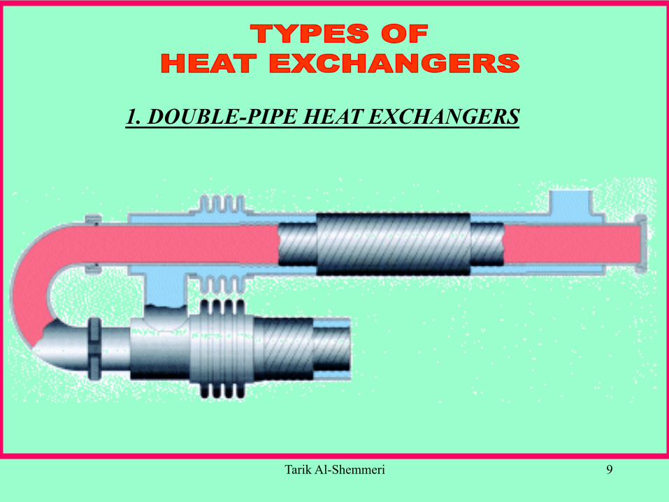
1. DOUBLE-PIPE HEAT EXCHANGERS
Tarik Al-Shemmeri 10
1. DOUBLE-PIPE HEAT EXCHANGERS
Two TYPES in this group:
1a. counter-flow
1b. parallel-flow
Tarik Al-Shemmeri 11
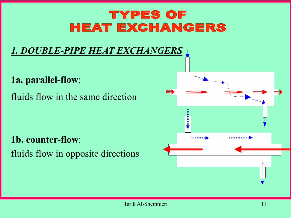
1. DOUBLE-PIPE HEAT EXCHANGERS
1a. parallel-flow:
fluids flow in the same direction
1b. counter-flow: fluids flow in opposite directions
Tarik Al-Shemmeri 12
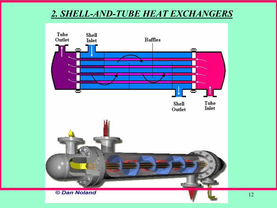
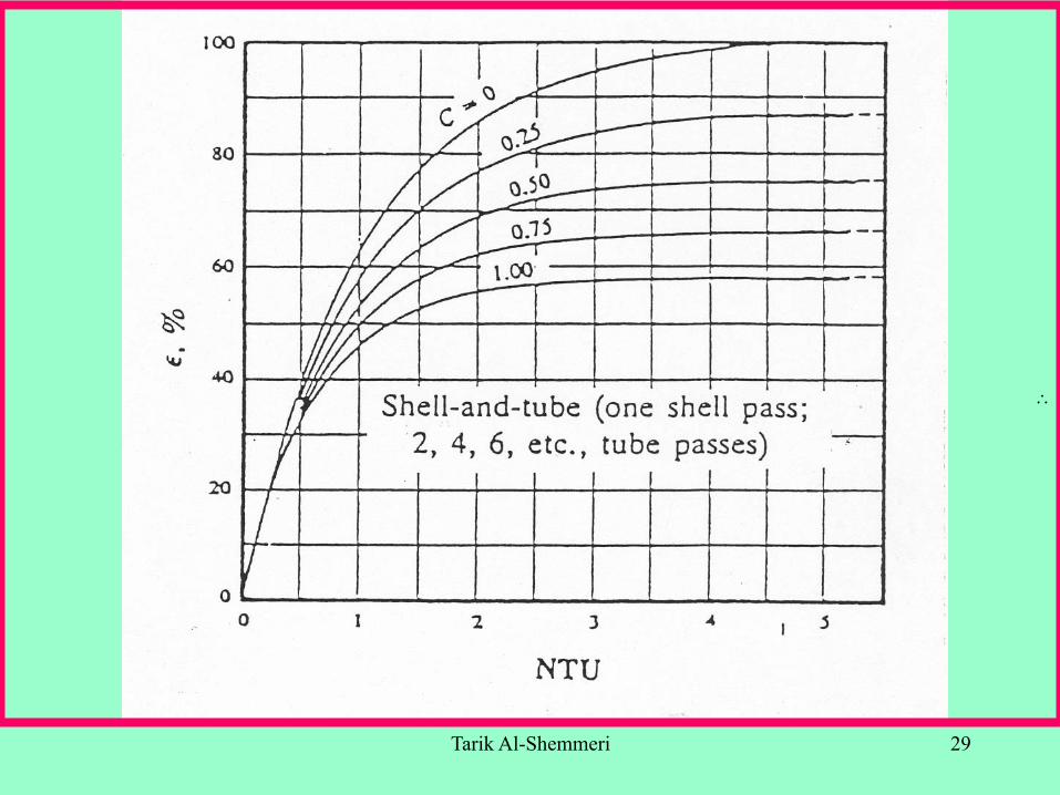
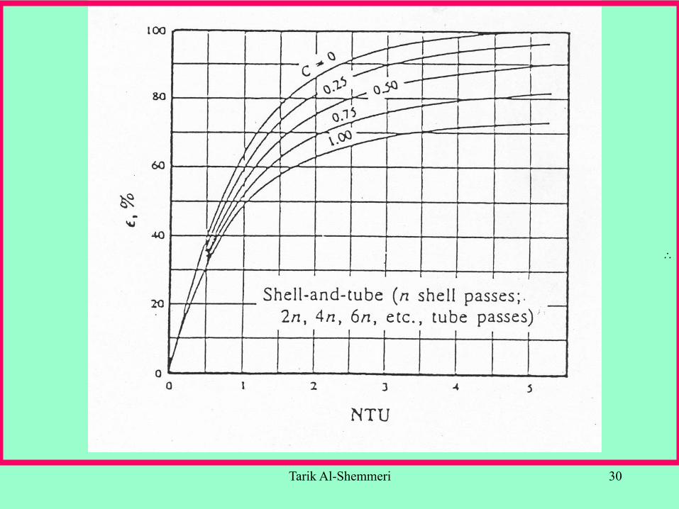
2. SHELL-AND-TUBE HEAT EXCHANGERS
Tarik Al-Shemmeri 13
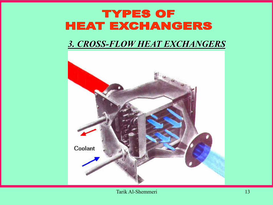
3. CROSS-FLOW HEAT EXCHANGERS
Tarik Al-Shemmeri 14
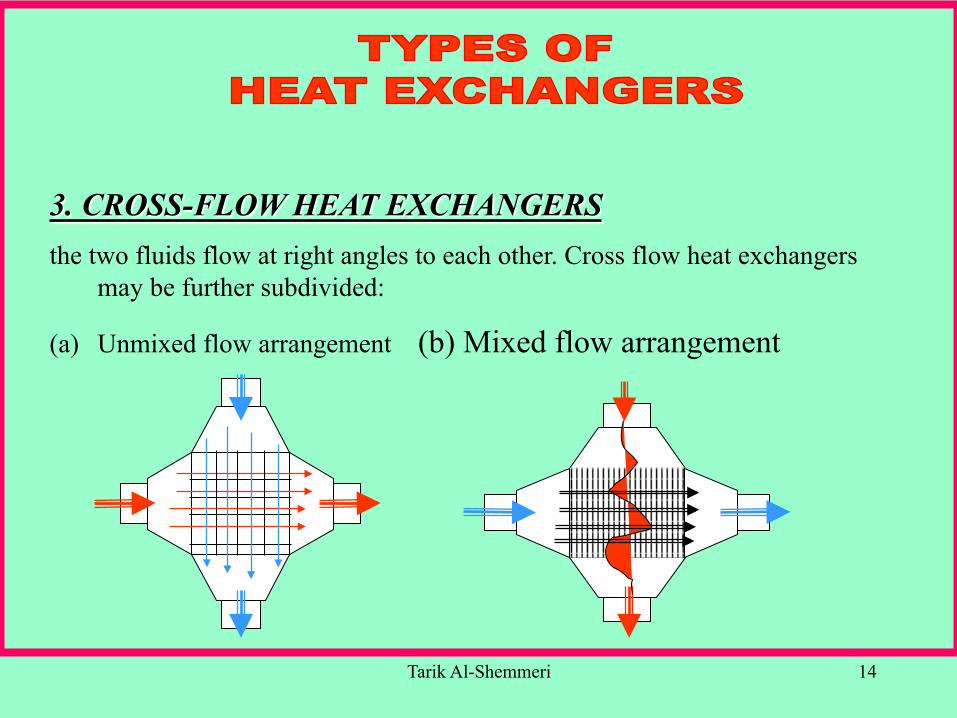
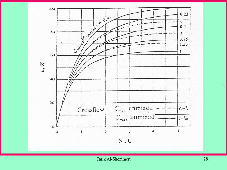
3. CROSS-FLOW HEAT EXCHANGERS the two fluids flow at right angles to each other. Cross flow heat exchangers
may be further subdivided:
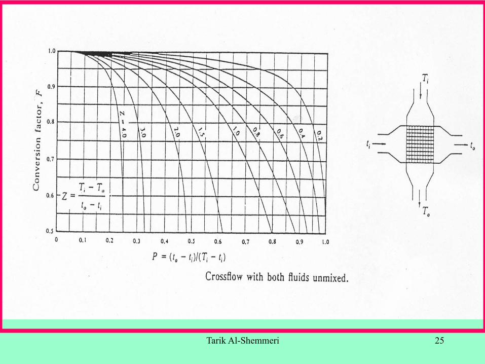
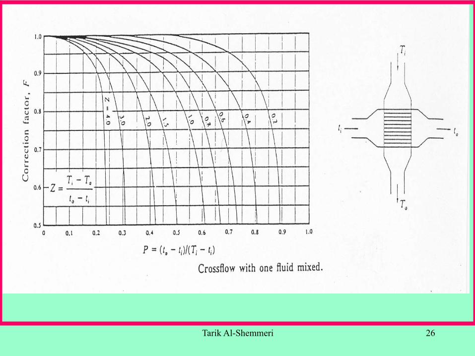
(a) Unmixed flow arrangement (b) Mixed flow arrangement
Tarik Al-Shemmeri 15
LrA
U
ii
i
π2
hrr
rrln
kr
h1
1
oo
i
i
oi
i
=
+⎟⎟⎠
⎞⎜⎜⎝
⎛+
=
LrA
rr
U
oo
i
oo
π2
h1
rrln
kr
h1
1
oi
oo
i
=
+⎟⎟⎠
⎞⎜⎜⎝
⎛+
=
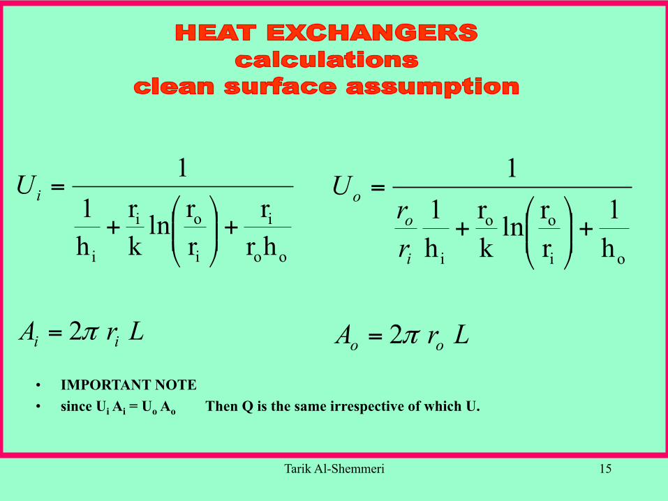
• IMPORTANT NOTE • since Ui Ai = Uo Ao Then Q is the same irrespective of which U.
Tarik Al-Shemmeri 16
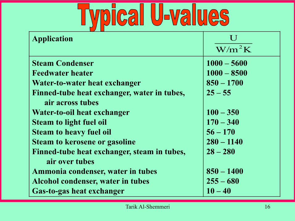
Application
Steam Condenser Feedwater heater Water-to-water heat exchanger Finned-tube heat exchanger, water in tubes, air across tubes Water-to-oil heat exchanger Steam to light fuel oil Steam to heavy fuel oil Steam to kerosene or gasoline Finned-tube heat exchanger, steam in tubes, air over tubes Ammonia condenser, water in tubes Alcohol condenser, water in tubes Gas-to-gas heat exchanger
1000 – 5600 1000 – 8500 850 – 1700 25 – 55 100 – 350 170 – 340 56 – 170 280 – 1140 28 – 280 850 – 1400 255 – 680 10 – 40
KW/mU2
Tarik Al-Shemmeri 17
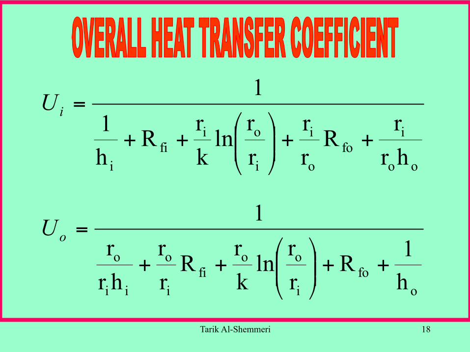
Sources of fouling a build-up of deposits due to harsh working environment and impurities in the working fluid/s, these will add a thermal insulating layer on either side of the heat exchanger surface, Rfi and Rfo respectively, and as such the overall heat transfer coefficient will be Lowered.
Tarik Al-Shemmeri 18
oo
ifo
o
i
i
oifi
i hrr
Rrr
rr
lnkr
Rh1
1
++⎟⎟⎠
⎞⎜⎜⎝
⎛++
=iU
ofo
i
oofi
i
o
ii
o
h1R
rr
lnkr
Rrr
hrr
1
++⎟⎟⎠
⎞⎜⎜⎝
⎛++
=oU

Tarik Al-Shemmeri 19
∴
Type of fluid Fouling factor, Rf m2 K/W
Seawater, below 50oC Above 50oC Treated boiler feedwater above 50oC Fuel oil Lubrication oil Alcohol vapours Steam, non-oil-bearing Industrial air Refrigerating liquid
0.0001 0.0020 0.0002 0.0009 0.0007 0.0001 0.0001 0.0004 0.0002
Tarik Al-Shemmeri 20
∴
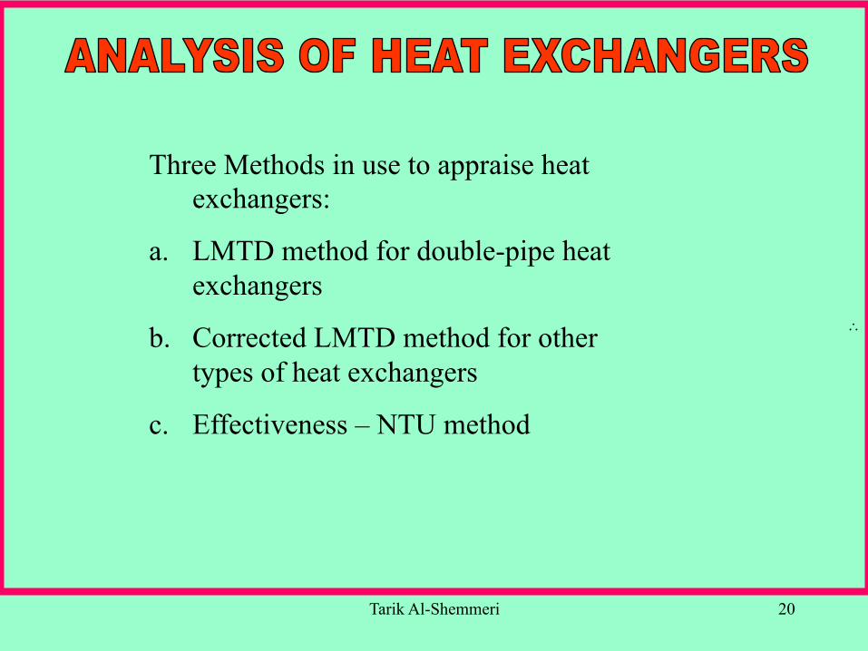
Three Methods in use to appraise heat exchangers:
a. LMTD method for double-pipe heat exchangers
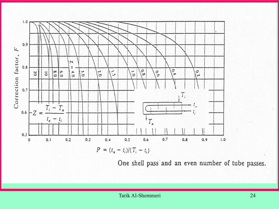
b. Corrected LMTD method for other types of heat exchangers
c. Effectiveness – NTU method
Tarik Al-Shemmeri 21
∴
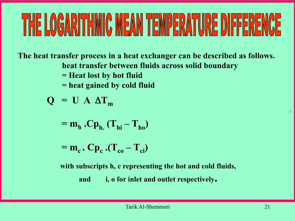
The heat transfer process in a heat exchanger can be described as follows. heat transfer between fluids across solid boundary = Heat lost by hot fluid = heat gained by cold fluid
Q = U A ΔTm
= mh .Cph. (Thi – Tho)
= mc . Cpc .(Tco – Tci)
with subscripts h, c representing the hot and cold fluids,
and i, o for inlet and outlet respectively.
Tarik Al-Shemmeri 22
∴
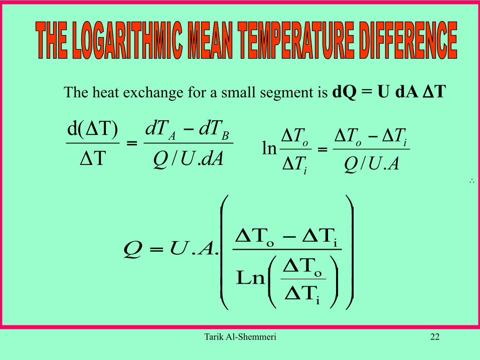
The heat exchange for a small segment is dQ = U dA ΔT
dAUQdTdT BA
./ΔTT)d( −
=Δ
AUQTT
TT io
i
o
./ln
Δ−Δ=
Δ
Δ
⎟⎟⎟⎟⎟
⎠
⎞
⎜⎜⎜⎜⎜
⎝
⎛
⎟⎟⎠
⎞⎜⎜⎝
⎛
ΔΔ
Δ−Δ=
i
o
io
TTLn
TT..AUQ
Tarik Al-Shemmeri 23
∴
This method for evaluating the performance of heat exchangers has the advantage that it does not require the calculation of the logarithmic mean temperature difference. Its main advantage is by using correction factors for heat exchangers which are NOT the standard parallel or counterflow.
Tarik Al-Shemmeri 24
∴
Tarik Al-Shemmeri 25
∴
Tarik Al-Shemmeri 26
∴
Tarik Al-Shemmeri 27
∴
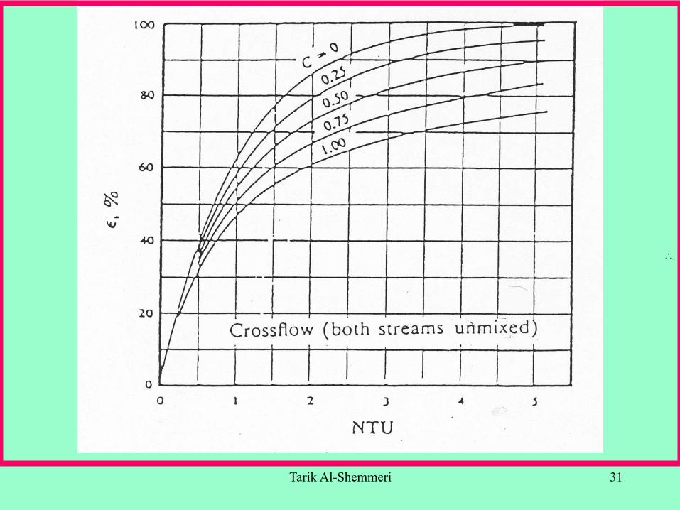
This method for evaluating the performance of heat exchangers has the advantage that it does not require the calculation of the logarithmic mean temperature difference. The method depends on the evaluation of three dimensionless parameters:
NTU EFFECTIVENESS
& CAPACITY RATIO
Tarik Al-Shemmeri 28
∴
Tarik Al-Shemmeri 29
∴
Tarik Al-Shemmeri 30
∴
Tarik Al-Shemmeri 31
∴

Tarik Al-Shemmeri 32
∴
Tarik Al-Shemmeri 33
∴
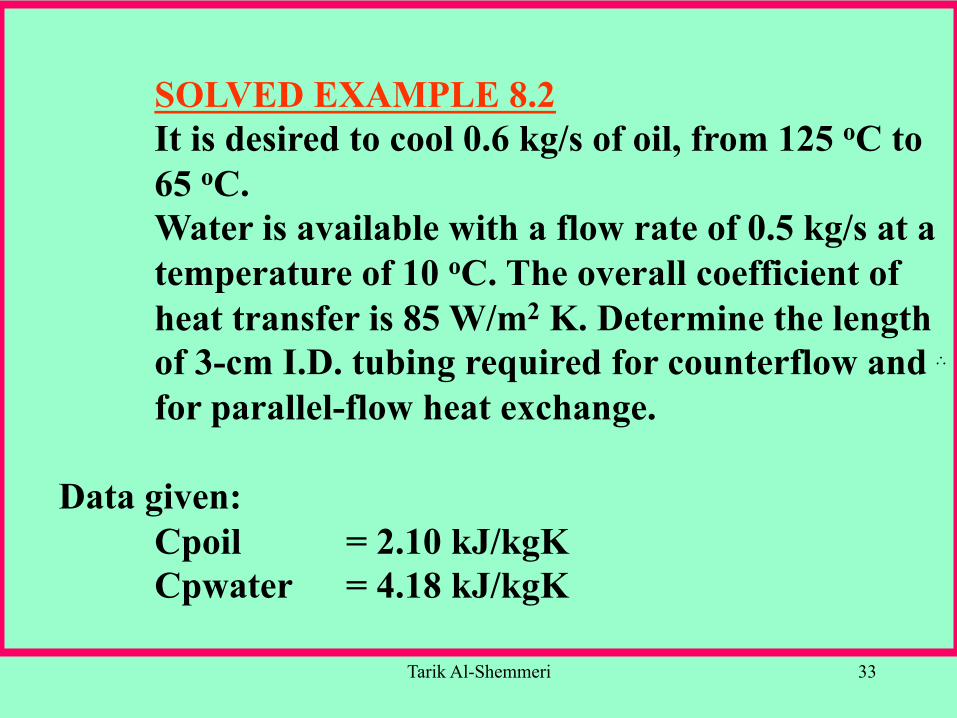
SOLVED EXAMPLE 8.2 It is desired to cool 0.6 kg/s of oil, from 125 oC to 65 oC. Water is available with a flow rate of 0.5 kg/s at a temperature of 10 oC. The overall coefficient of heat transfer is 85 W/m2 K. Determine the length of 3-cm I.D. tubing required for counterflow and for parallel-flow heat exchange.
Data given: Cpoil = 2.10 kJ/kgK Cpwater = 4.18 kJ/kgK

Tarik Al-Shemmeri 34
∴
SOLUTION EXAMPLE 8.2
Equating heat contents of water and oil:
17.36)18.4)(50.0()60)(10.2)(60.0(
].[]..[
==Δ
=Δw
oilw Cpm
TCpmT
hence Two = 36.17 + 10 = 46.17C
Tarik Al-Shemmeri 35
∴
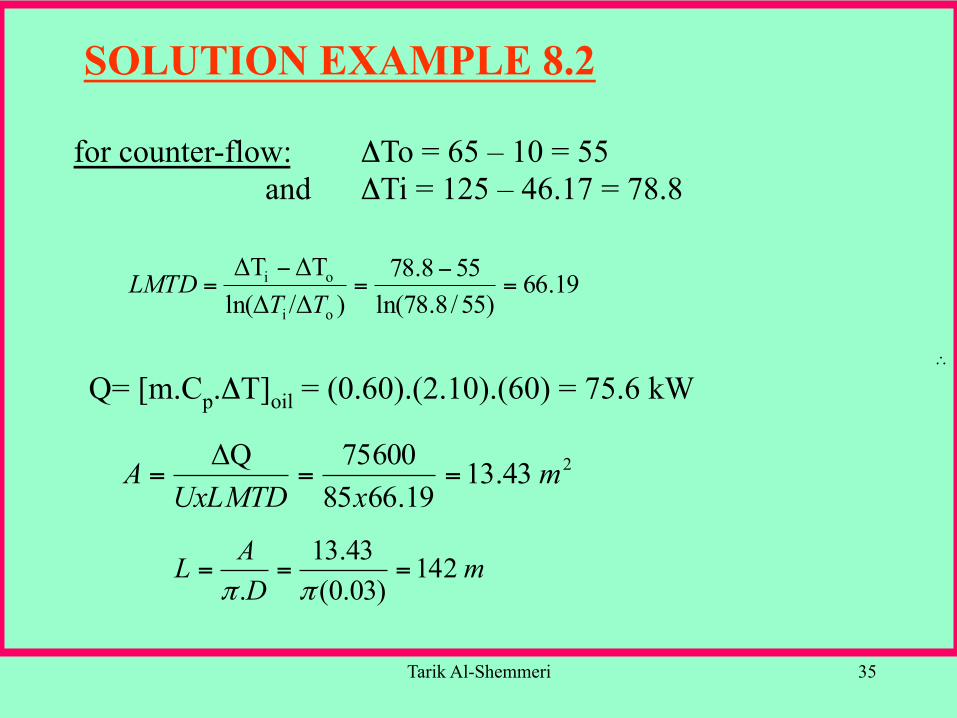
for counter-flow: ΔTo = 65 – 10 = 55 and ΔTi = 125 – 46.17 = 78.8
19.66)55/8.78ln(
558.78)/Δln(Δ
ΔTΔT
oi
oi =−
=−
=TT
LMTD
Q= [m.Cp.ΔT]oil = (0.60).(2.10).(60) = 75.6 kW
243.1319.6685
75600QΔ mxUxLMTD
A ===
mDAL 142
)03.0(43.13
.===
ππ
SOLUTION EXAMPLE 8.2
Tarik Al-Shemmeri 36
∴
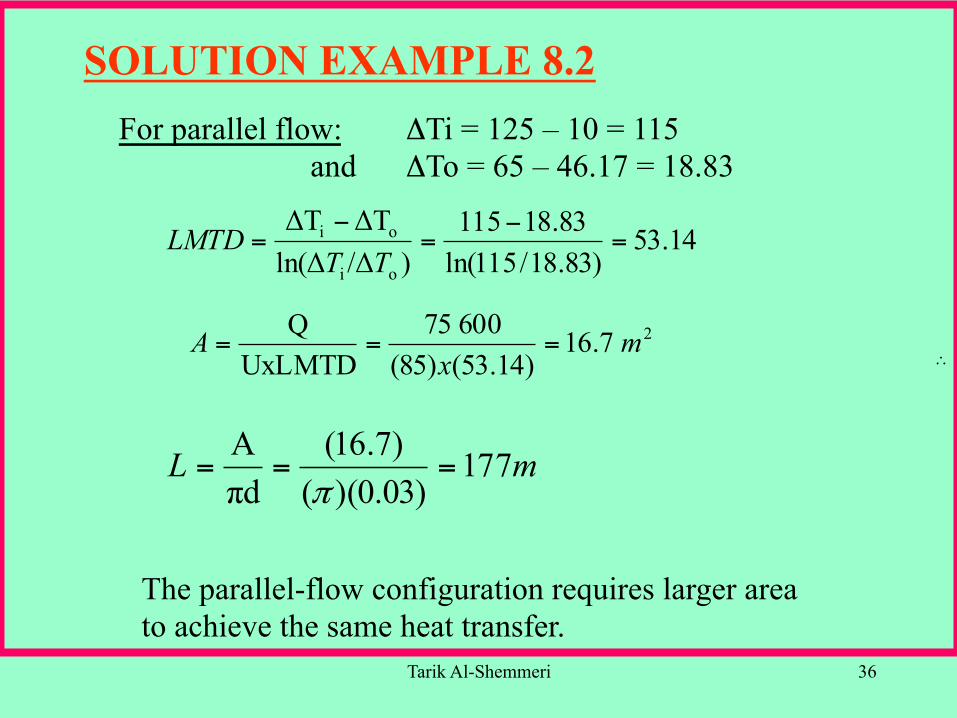
For parallel flow: ΔTi = 125 – 10 = 115 and ΔTo = 65 – 46.17 = 18.83
14.53)83.18/115ln(
83.18115)/Δln(Δ
ΔTΔT
oi
oi =−
=−
=TT
LMTD
27.16)14.53()85(
60075UxLMTD
Q mx
A ===
mL 177)03.0)(()7.16(
dπA
===π
The parallel-flow configuration requires larger area to achieve the same heat transfer.
SOLUTION EXAMPLE 8.2

Tarik Al-Shemmeri 37
∴
for counter-flow: ΔTo = 65 – 10 = 55 and ΔTi = 125 – 46.17 = 78.8
19.66)55/8.78ln(
558.78)/Δln(Δ
ΔTΔT
oi
oi =−
=−
=TT
LMTD
Q= [m. Cp .ΔT ]oil = (0.60).(2.10).(60) = 75.6 kW
243.1319.6685
75600QΔ mxUxLMTD
A ===
mDAL 142
)03.0(43.13
.===
ππ
SOLUTION EXAMPLE 8.2

How to get the most out of your heating
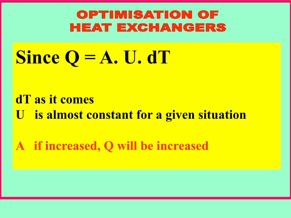
Since Q = A. U. dT dT as it comes U is almost constant for a given situation A if increased, Q will be increased
The use of fins in heat exchangers
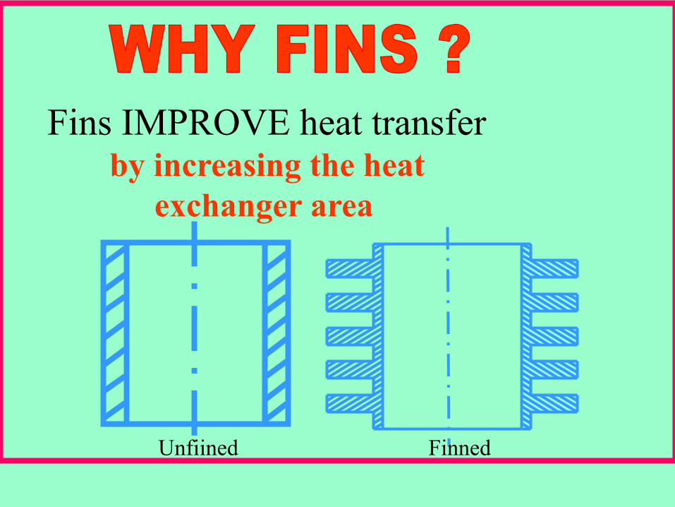
Fins IMPROVE heat transfer by increasing the heat
exchanger area
Unfiined Finned
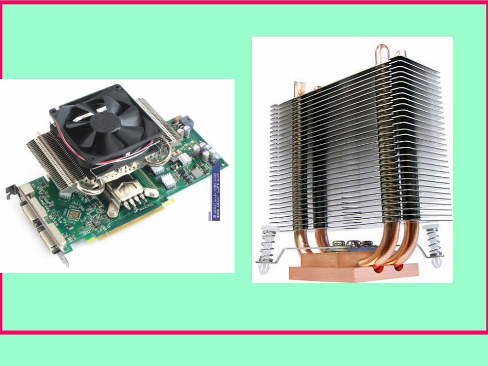
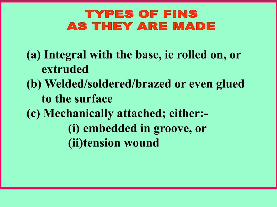
(a) Integral with the base, ie rolled on, or extruded
(b) Welded/soldered/brazed or even glued to the surface
(c) Mechanically attached; either:- (i) embedded in groove, or (ii) tension wound

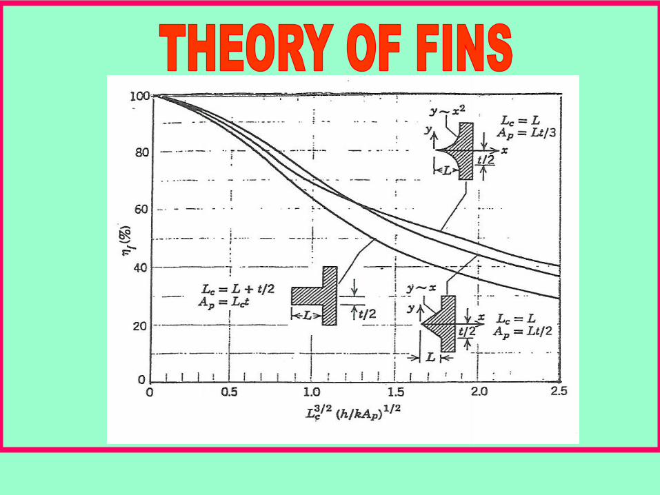
Typical fins are • Annular, or Flat; for either 3 profiles: • Rectangular • Triangular, and • Parabolic
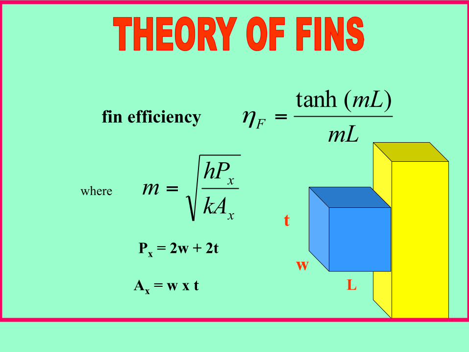
mLmL
F)(tanh
=η fin efficiency
where x
x
kAhPm =
t w
L Px = 2w + 2t
Ax = w x t
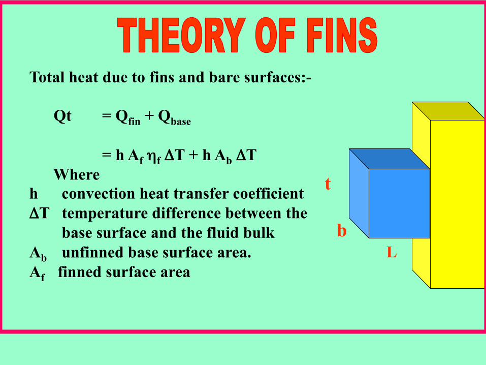
Total heat due to fins and bare surfaces:-
Qt = Qfin + Qbase
= h Af ηf ΔT + h Ab ΔT Where
h convection heat transfer coefficient ΔT temperature difference between the
base surface and the fluid bulk Ab unfinned base surface area. Af finned surface area
t b
L

f
i
oof
i
ii
i
AA
hkx
AA
h
TAQ
ηη11
+Δ
+
Δ=
Could have fins, on the inner and outer surface/s

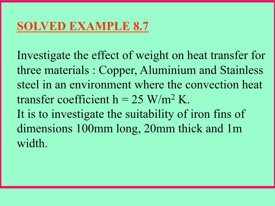
SOLVED EXAMPLE 8.7 Investigate the effect of weight on heat transfer for three materials : Copper, Aluminium and Stainless steel in an environment where the convection heat transfer coefficient h = 25 W/m2 K. It is to investigate the suitability of iron fins of dimensions 100mm long, 20mm thick and 1m width.
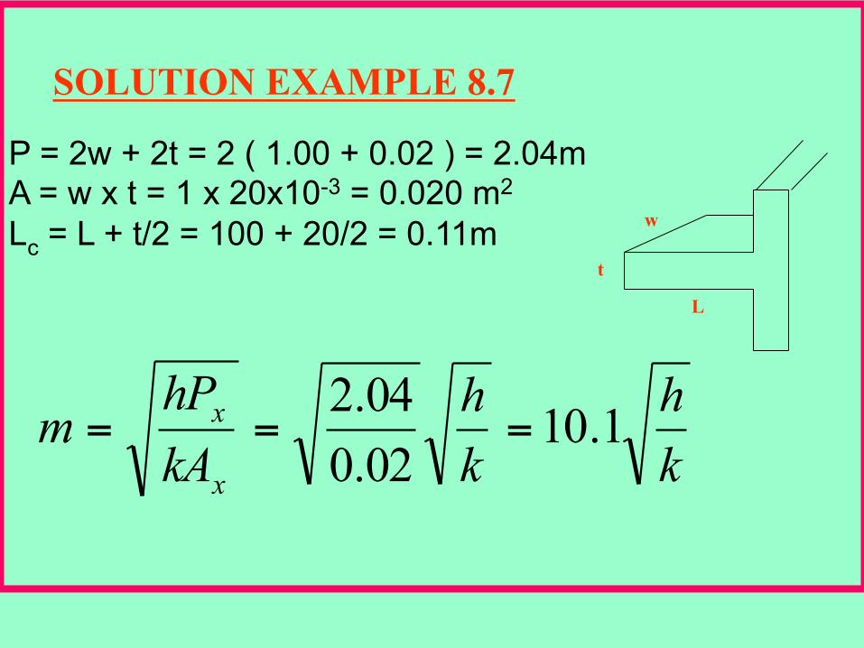
SOLUTION EXAMPLE 8.7
P = 2w + 2t = 2 ( 1.00 + 0.02 ) = 2.04m A = w x t = 1 x 20x10-3 = 0.020 m2 Lc = L + t/2 = 100 + 20/2 = 0.11m
kh
kh
kAhPm
x
x 1.1002.004.2
===
L
w
t
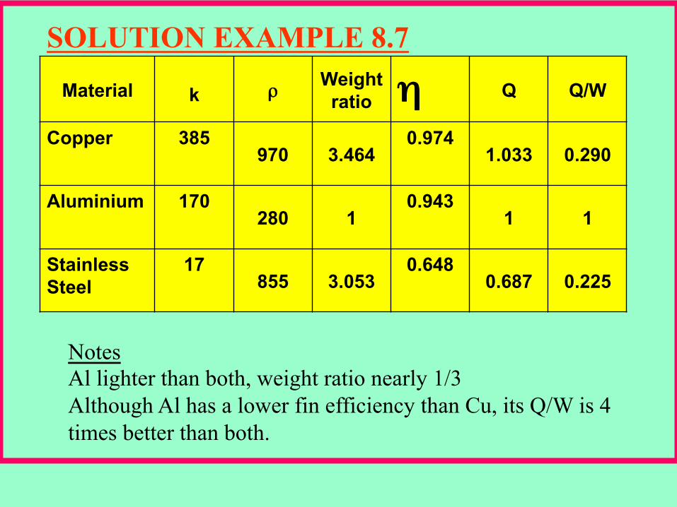
SOLUTION EXAMPLE 8.7
fη
Material k ρ Weight
ratio η Q Q/W Copper 385
970 3.464 0.974 1.033 0.290
Aluminium 170 280 1 0.943
1 1 Stainless Steel
17 855 3.053 0.648
0.687 0.225
Notes Al lighter than both, weight ratio nearly 1/3 Although Al has a lower fin efficiency than Cu, its Q/W is 4 times better than both.
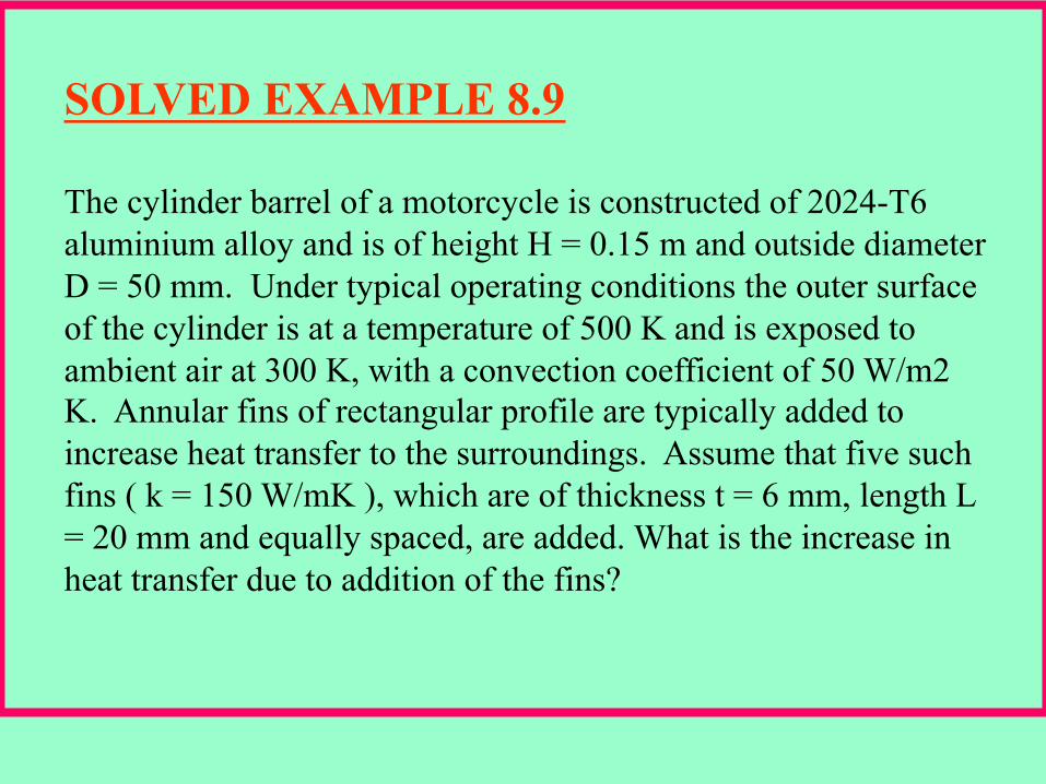
SOLVED EXAMPLE 8.9 The cylinder barrel of a motorcycle is constructed of 2024-T6 aluminium alloy and is of height H = 0.15 m and outside diameter D = 50 mm. Under typical operating conditions the outer surface of the cylinder is at a temperature of 500 K and is exposed to ambient air at 300 K, with a convection coefficient of 50 W/m2 K. Annular fins of rectangular profile are typically added to increase heat transfer to the surroundings. Assume that five such fins ( k = 150 W/mK ), which are of thickness t = 6 mm, length L = 20 mm and equally spaced, are added. What is the increase in heat transfer due to addition of the fins?
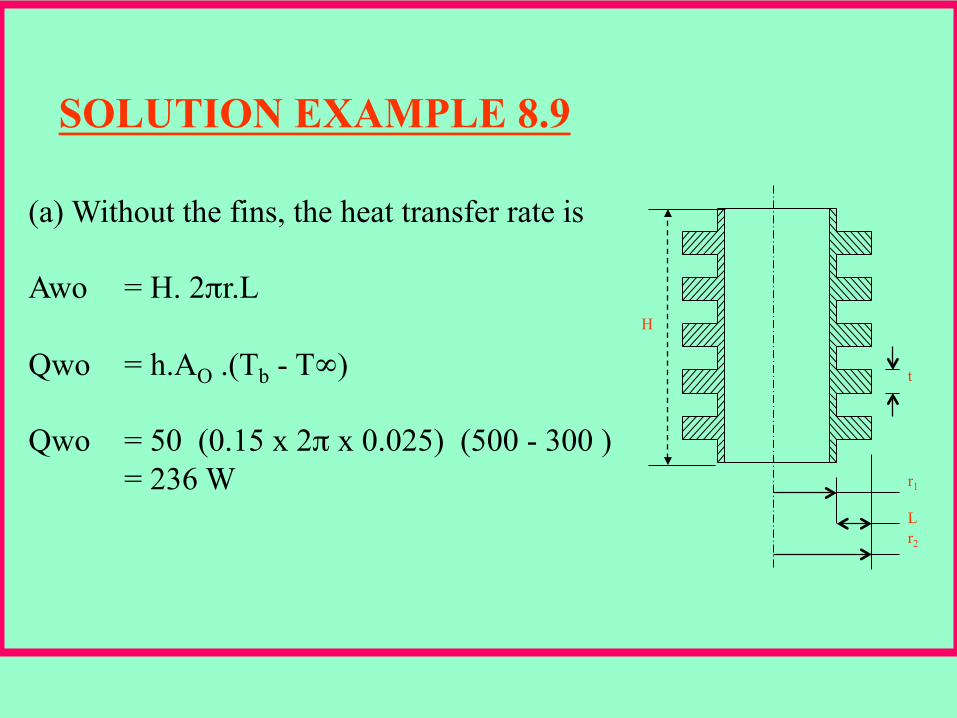
SOLUTION EXAMPLE 8.9
H t
r1 L r2
(a) Without the fins, the heat transfer rate is Awo = H. 2πr.L Qwo = h.AO .(Tb - T∞) Qwo = 50 (0.15 x 2π x 0.025) (500 - 300 )
= 236 W
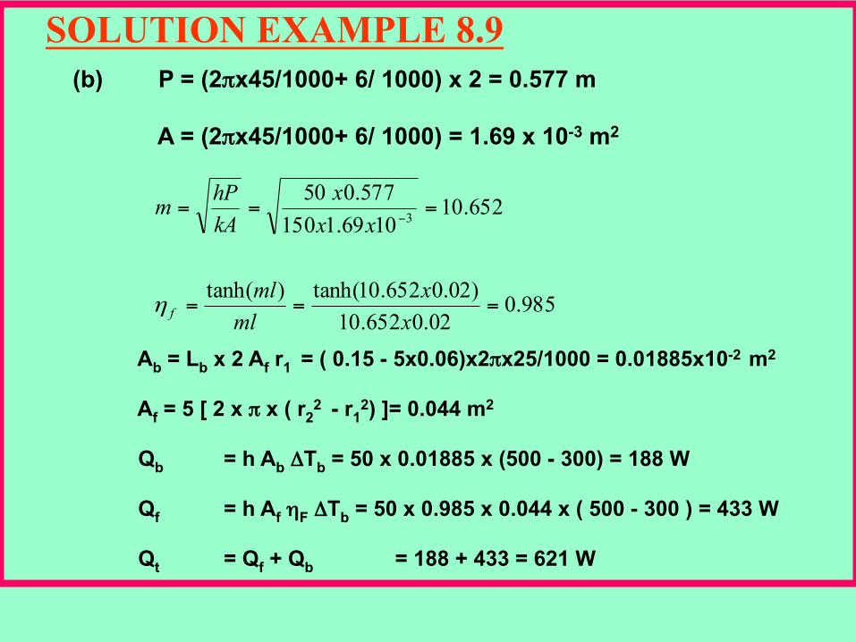
SOLUTION EXAMPLE 8.9 (b) P = (2πx45/1000+ 6/ 1000) x 2 = 0.577 m
A = (2πx45/1000+ 6/ 1000) = 1.69 x 10⁻³ m2
985.002.0652.10
)02.0652.10tanh()tanh(
652.101069.1150577.050
3
===
===−
xx
mlml
xxx
kAhPm
fη
Ab = Lb x 2 Af r1 = ( 0.15 - 5x0.06)x2πx25/1000 = 0.01885x10⁻² m2
Af = 5 [ 2 x π x ( r2
2 - r12) ]= 0.044 m2
Qb = h Ab ΔTb = 50 x 0.01885 x (500 - 300) = 188 W
Qf = h Af ηF ΔTb = 50 x 0.985 x 0.044 x ( 500 - 300 ) = 433 W
Qt = Qf + Qb = 188 + 433 = 621 W