a gunsmithing student's diary of a pistol build
TRANSCRIPT

Project
Limited 10
Diary of a Pistol Build
Jason Lisenbey
Competition Firearms

Project Limited 10
2
The following pages are notes and observations that I made while building this pistol. The dates on the head-ings are not necessarily the day the work was done, but when I made the diary entry. The pictures included are not meant for instruction, but rather they are to illustrate what I am talking about in the text of the entry. My hope is that while reading through these pages you will under-
stand the process that ended with this pistol.
Jason Lisenbey
3
For this project, I wanted to build something
requiring more skill. I was also looking to get
that “cool” factor that often results in men buy-
ing new toys.
This class is focused on competition fire-
arms and I have recently been interested in
USPSA competition. At first I wanted to try
building an open gun. This definitely hits the
cool factor mark, but from what I understand
you may have to build your ammunition to
work the gun you just built. I have a tendency
to go too far and try to learn too many new
skills at once.
I instead decided to build a pistol for Lim-
ited competition. Since I was scaling down, I
might as well go down a little more and make a
transition pistol for those moving up from Sin-
gle Stack to Limited 10. This will be a Limited-
style gun with a slim grip for those who prefer
it.
This is what I had in mind when deciding
what parts to order. The diary of the build fol-
lows.
Jason Lisenbey
Project Limited 10
4
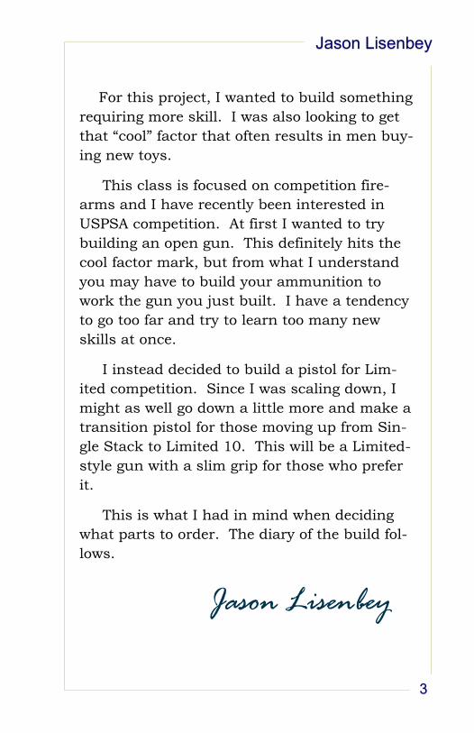
Here is the slide. It is a STI Unique
slide is totally bald. That means there are no cuts on it yet.
Here is the frame. It is a STI Master frame. It is a single
stack 1911 frame with a long dust cover.
This will be my first time to fit a slide to a frame. It seems that
the typical way to do it is to work on the frame rails with files
and stones until it is a tight fit, then use lapping compound to
get it the rest of the way there. I don’t want to do it that way.
My plan is to use only files and stones to get it to fit. The idea
is when you lap it in, there has to be room for the lapping
compound between slide and frame. With stones only, a bet-
ter, tighter, and smoother fit can be achieved.
I have measured the slot in the frame rails. It is 0.110”.
The bottom rail on the slide is 0.120”.
Figure 1 - STI "Unique" slide, bald
Figure 2 - STI "Master" frame. The dust cover is meant to extend the length of the slide.
Aug 20, 2014
Jason Lisenbey
5
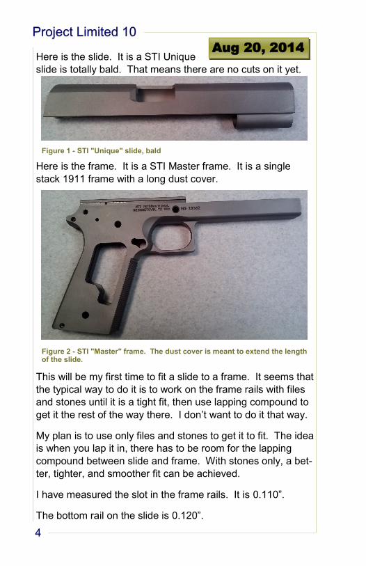
I think this means that I
will have to remove
about 0.010” from the
bottom of the slide to fit
it in the frame rails.
That’s a lot for files and
stones. It may be bet-
ter to mill it off. I’m
afraid that my milling
skills aren’t very good
and I may make a mis-
take.
I saw a video on
YouTube in which a
guy was selling a fix-
ture for stoning the
frame rails. I got excit-
ed about it and wanted
to make it in the shop.
After studying the
frame, I’ve decided that
it is already easy
enough to stone the rails and keep them square. I won’t
make the fixture (for now).
I’m going to take material off the bottom
surface of the slide by hand. I’ll meas-
ure my progress by slide overall height.
Right now it is 1.000”. I’ll use sandpa-
per and stones for this.
A fellow student is using a magnet to
hold the sandpaper. The magnet pro-
vides the force and you just slide it back
and forth. Seems like a pretty good
trick.
Figure 3 - the rails on the frame
Slot is 0.110”
Rail is 0.098”
Figure 4 - the rails on the slide
Remove metal
Slot is 0.100”
Rail is 0.120”
Figure 5 - Frame rail fitting fixture sold by Buchanan Gunsmithing
Project Limited 10
6
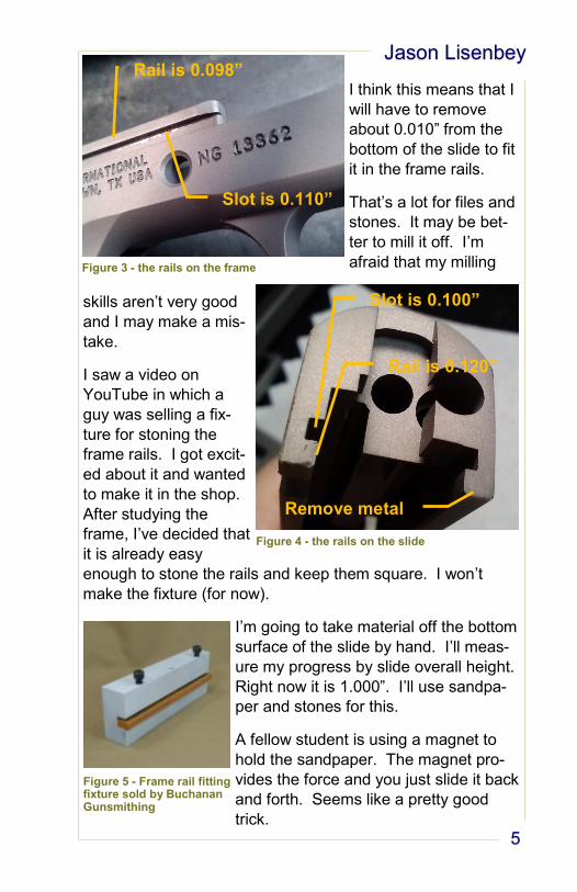
I’ve come to real-
ize that when you
do this by hand,
there is no way to
know if you are
making flat cuts.
On a mill, they are
flat, but may be
tapered.
I started around
10:00 am, and it is
11:30. I still have
around 5 thou to
go. I’m switching
to a mill file.
Hopefully I will
keep straight lines.
I have totally regressed to the 1st semester. I am using eve-
rything I learned making the tap plate in order to keep the
bottom surface of the slide flat.
Okay, its 1 pm and I have the bottom edge of the slide to
within a couple of thousandths. I’m going to start working on
the frame rail width. They measure 0.765”. The channel
width in the slide is 0.750”. In order to fix this, I need to put
the frame in the mill. I should have went to the mill this morn-
ing.
Talked to George for a while. He showed me the Brownell’s
slide/frame rail file. It’s simple a pillar file with some of the
teeth ground off. I tried using it, but all I can figure it is good
for is de-burring getting out uneven areas. I think I can grind
my own files.
I’m going to shut it down for today and set up a mill in the
morning. It’s 2 pm.
Figure 6 – The frame rails need to fit into here.
Channel is 0.750”
wide
Jason Lisenbey
7
I’m logging all of my working hours into Access so I can keep
track of how much time each project takes me.
I also borrowed a jig to hold the frame in the mill from Adam.
I used the jig, but I don’t think it is needed much. You proba-
bly would have to really crank down on the mill vise to crush
the magazine well. I’m sure people do it, but I don’t think I
will.
Project Limited 10
8
Okay, I went to the mill and re-
moved .007 from each frame rail to get .752 on the
front of the rail and .7515 on the rear of the rail. Now
the slide is too loose. What happened to the .750 slot
that I measured? Lesson learned: measuring the slot
with cheap calipers is not a good ideal. Get a better
way to measure that. It’s still a nice fit, just not the
perfection I was looking for. I think once everything
gets fitted, the slight noticeable wiggle may disappear.
Before I cut the slide for the barrel rib, I’m going to
study the problem a little more.
In the meantime, the slide won’t go back all the way
before it sticks. It’s the bottom surface of the slide.
I’m going to fix that today.
It didn’t take long. About 20 minutes with Dykem and
sandpaper wrapped around a flat stone. The slide
goes all the way back without sticking.
Aug 25, 2014
Jason Lisenbey
9
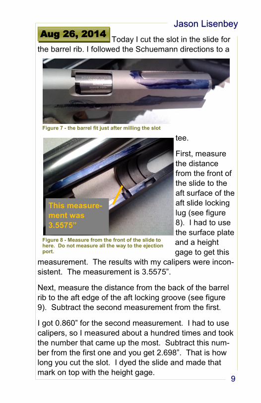
Today I cut the slot in the slide for
the barrel rib. I followed the Schuemann directions to a
tee.
First, measure
the distance
from the front of
the slide to the
aft surface of the
aft slide locking
lug (see figure
8). I had to use
the surface plate
and a height
gage to get this
measurement. The results with my calipers were incon-
sistent. The measurement is 3.5575”.
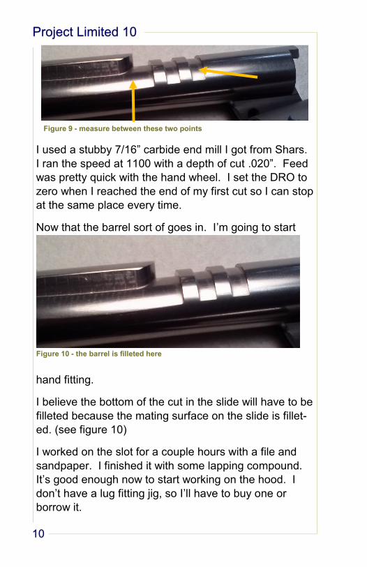
Next, measure the distance from the back of the barrel
rib to the aft edge of the aft locking groove (see figure
9). Subtract the second measurement from the first.
I got 0.860” for the second measurement. I had to use
calipers, so I measured about a hundred times and took
the number that came up the most. Subtract this num-
ber from the first one and you get 2.698”. That is how
long you cut the slot. I dyed the slide and made that
mark on top with the height gage.
Aug 26, 2014
Figure 7 - the barrel fit just after milling the slot
Figure 8 - Measure from the front of the slide to here. Do not measure all the way to the ejection port.
This measure-
ment was
3.5575”
Project Limited 10
10
I used a stubby 7/16” carbide end mill I got from Shars.
I ran the speed at 1100 with a depth of cut .020”. Feed
was pretty quick with the hand wheel. I set the DRO to
zero when I reached the end of my first cut so I can stop
at the same place every time.
Now that the barrel sort of goes in. I’m going to start
hand fitting.
I believe the bottom of the cut in the slide will have to be
filleted because the mating surface on the slide is fillet-
ed. (see figure 10)
I worked on the slot for a couple hours with a file and
sandpaper. I finished it with some lapping compound.
It’s good enough now to start working on the hood. I
don’t have a lug fitting jig, so I’ll have to buy one or
borrow it.
Figure 9 - measure between these two points
Figure 10 - the barrel is filleted here
Jason Lisenbey
11
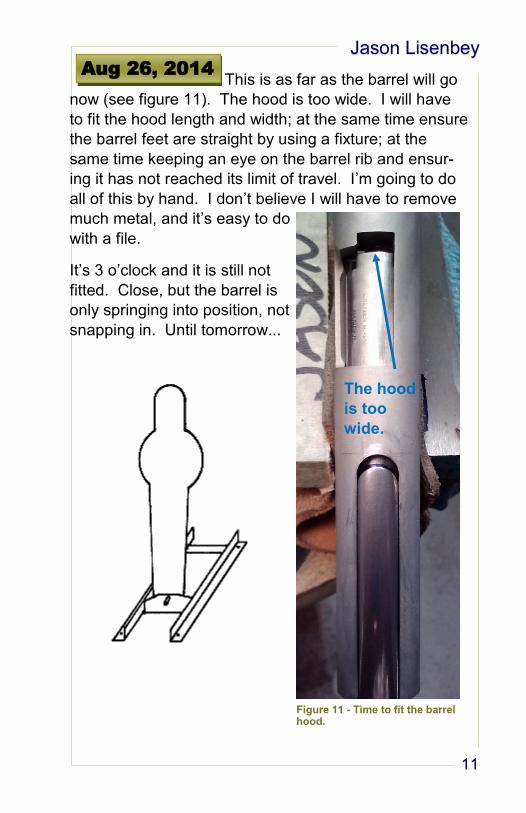
This is as far as the barrel will go
now (see figure 11). The hood is too wide. I will have
to fit the hood length and width; at the same time ensure
the barrel feet are straight by using a fixture; at the
same time keeping an eye on the barrel rib and ensur-
ing it has not reached its limit of travel. I’m going to do
all of this by hand. I don’t believe I will have to remove
much metal, and it’s easy to do
with a file.
It’s 3 o’clock and it is still not
fitted. Close, but the barrel is
only springing into position, not
snapping in. Until tomorrow...
Aug 26, 2014
Figure 11 - Time to fit the barrel hood.
The hood
is too
wide.
Project Limited 10
12
Yesterday was a little bit frustrat-
ing for me. I stopped working
around 2:30 pm, with around 5 hours of barrel fitting.
I’m afraid I may have taken to much metal off of the
hood and breech. I didn’t realize why the barrel wasn’t
going into lockup until right when I decided to stop for
the day.
The bull barrel has a nice fit at the front of the slide be-
cause of the lapping that I did the other day. What I did-
n’t realize is that the nice muzzle fit will keep the barrel
from moving upward into lockup. I kept removing mate-
rial. I do still have light contact where the slide breech
contacts the barrel to move it forward.
I noticed this when I realized that when the barrel is all
the way back to the breech, I could spring it up into the
locking lugs by pushing up on the barrel feet.
Today I am going to work on fitting the barrel to the
slide. I know the slide is the least expensive part by
about $100, but I have put a lot of work into the slot for
the hybrid barrel. Also, I don’t really like the barrel now
because I may have ruined the fit of the barrel hood.
We’ll see how it works out today.
10:13 am – I just rounded off the sharp corners on the
slide at the bottom the barrel hole at the muzzle.
It made about 5 thou difference in lockup and I got rid of
the sharp corners (who needs them). I have 17 thou
lock up.
11:50 am – I’m up to 32 thou. I beginning to work on
the barrel top lugs. The Schuemann instructions say to
get at least .045 lockup. The lugs are only .042 deep.
I’m beginning to again get contact on the left side of the
hybrid slot.
Aug 28, 2014
Jason Lisenbey
13
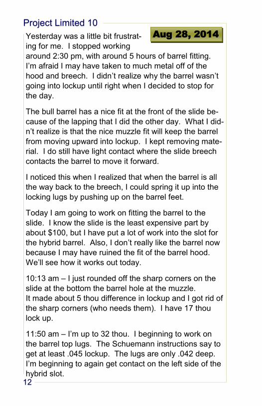
1:20 pm – I stalled at .033 thou. It turns out the rear lug
slot in the barrel is only 35 thou deep. I have to file it
out. Frustrating.
Note: need aggressive needle files less than .150 wide,
with at least one safe side.
2:40 pm – Achieved .048 lockup with no spring in the
barrel. I had to take a little more off of the muzzle end
to get out more barrel spring.
Done for the day.
Figure 12 - Removing metal from the muzzle end of the barrel. The extra metal is preventing barrel lockup.
Project Limited 10
14
After the barrel locks up, there
is .014”
forward/aft wiggle room. I’ve spent all day thinking
about it and talked to everyone that knows anything
about 1911s. I’ve decided to continue with the build. I
don’t think it will cause a problem.
The reason this problem exists is because I removed
metal from the breech end of the barrel. I didn’t know
what I was doing.
No progress today. I can’t fit the barrel any more until
more parts come in. I can only do cuts on the slide.
I really need to study the rear sight dimensions before
cutting. I have a Dawson adjustable rear for a Novak
cut. My slide has no rear cut at all. I’m thinking that the
slide needs to be flat-topped before deciding how deep
to make the dovetail. The rear portion needs to be
about .125 above the bottom of the dovetail.
Sept 2, 2014
Jason Lisenbey
15
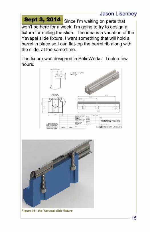
Since I’m waiting on parts that
won’t be here for a week, I’m going to try to design a
fixture for milling the slide. The idea is a variation of the
Yavapai slide fixture. I want something that will hold a
barrel in place so I can flat-top the barrel rib along with
the slide, at the same time.
The fixture was designed in SolidWorks. Took a few
hours.
Sept 3, 2014
Figure 13 - the Yavapai slide fixture
Project Limited 10
16
Today I’m just catching up on data
entry for the Access database. I went this morning to
Prescott Steel to pick up material to make the slide fix-
ture designed yesterday, and some extra to practice
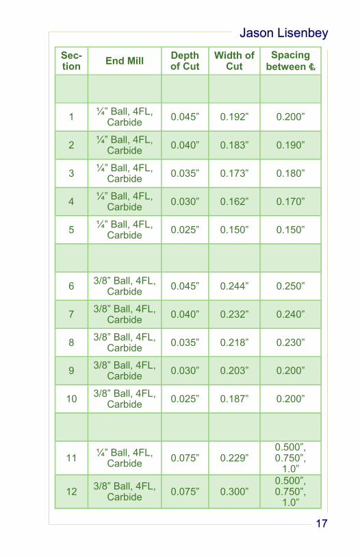
slide serrations with. I’ll going to do some math to figure
out measurements to cut slide serrations with a ball end
mill. Also, I need to study for a test in CNC class. That
will be all for today. I’m going to add an hour of re-
search time to the Limited 10 project for doing the math.
The cuts I will make on the 1” square CR stock for prac-
tice are on the facing page.
I think I am going to like 90° cuts on the rear serrations,
and 75° cuts for the front (decorative) serrations.
Sept 4, 2014
Jason Lisenbey
17
Sec-tion
End Mill Depth of Cut
Width of Cut
Spacing between ℄
1 ¼” Ball, 4FL,
Carbide 0.045” 0.192” 0.200”
2 ¼” Ball, 4FL,
Carbide 0.040” 0.183” 0.190”
3 ¼” Ball, 4FL,
Carbide 0.035” 0.173” 0.180”
4 ¼” Ball, 4FL,
Carbide 0.030” 0.162” 0.170”
5 ¼” Ball, 4FL,
Carbide 0.025” 0.150” 0.150”
6 3/8” Ball, 4FL,
Carbide 0.045” 0.244” 0.250”
7 3/8” Ball, 4FL,
Carbide 0.040” 0.232” 0.240”
8 3/8” Ball, 4FL,
Carbide 0.035” 0.218” 0.230”
9 3/8” Ball, 4FL,
Carbide 0.030” 0.203” 0.200”
10 3/8” Ball, 4FL,
Carbide 0.025” 0.187” 0.200”
11 ¼” Ball, 4FL,
Carbide 0.075” 0.229”
0.500”, 0.750”,
1.0”
12 3/8” Ball, 4FL,
Carbide 0.075” 0.300”
0.500”, 0.750”,
1.0”
Project Limited 10
18
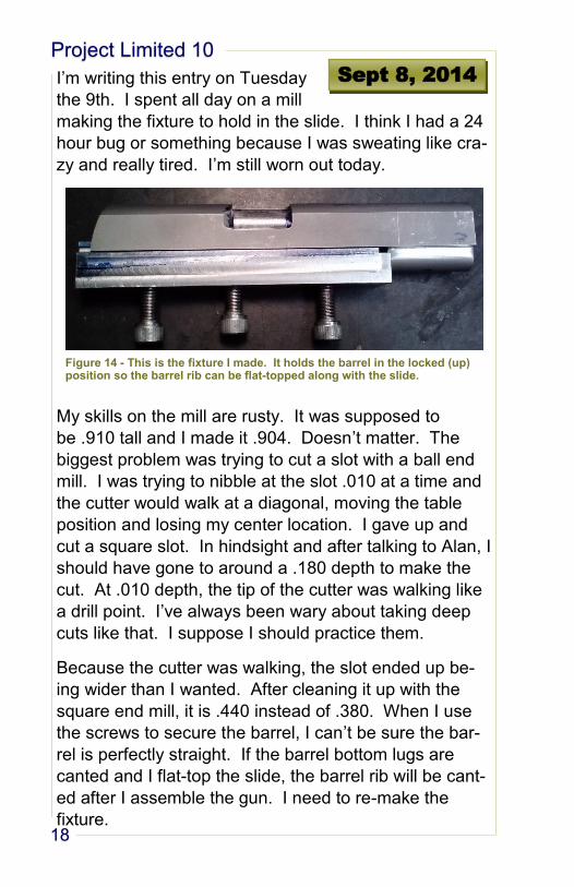
I’m writing this entry on Tuesday
the 9th. I spent all day on a mill
making the fixture to hold in the slide. I think I had a 24
hour bug or something because I was sweating like cra-
zy and really tired. I’m still worn out today.
My skills on the mill are rusty. It was supposed to
be .910 tall and I made it .904. Doesn’t matter. The
biggest problem was trying to cut a slot with a ball end
mill. I was trying to nibble at the slot .010 at a time and
the cutter would walk at a diagonal, moving the table
position and losing my center location. I gave up and
cut a square slot. In hindsight and after talking to Alan, I
should have gone to around a .180 depth to make the
cut. At .010 depth, the tip of the cutter was walking like
a drill point. I’ve always been wary about taking deep
cuts like that. I suppose I should practice them.
Because the cutter was walking, the slot ended up be-
ing wider than I wanted. After cleaning it up with the
square end mill, it is .440 instead of .380. When I use
the screws to secure the barrel, I can’t be sure the bar-
rel is perfectly straight. If the barrel bottom lugs are
canted and I flat-top the slide, the barrel rib will be cant-
ed after I assemble the gun. I need to re-make the
fixture.
Sept 8, 2014
Figure 14 - This is the fixture I made. It holds the barrel in the locked (up) position so the barrel rib can be flat-topped along with the slide.
Jason Lisenbey
19
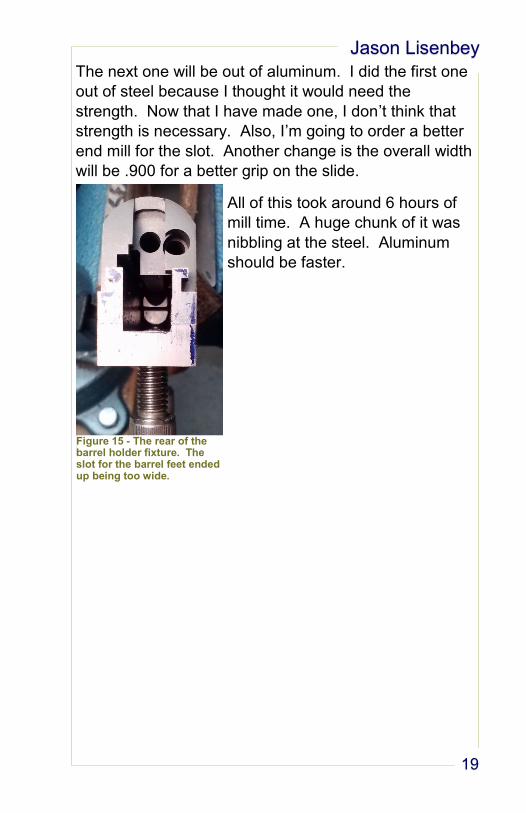
The next one will be out of aluminum. I did the first one
out of steel because I thought it would need the
strength. Now that I have made one, I don’t think that
strength is necessary. Also, I’m going to order a better
end mill for the slot. Another change is the overall width
will be .900 for a better grip on the slide.
All of this took around 6 hours of
mill time. A huge chunk of it was
nibbling at the steel. Aluminum
should be faster.
Figure 15 - The rear of the barrel holder fixture. The slot for the barrel feet ended up being too wide.
Project Limited 10
20
All I have done today is reconsider
the barrel holder fixture. I’m going to re-do it in alumi-
num like mentioned above. Also, I will attach a remova-
ble ½” plate to the bottom for putting the slide on its side
in the mill vise. This way I can flat top the slide by side
milling, and use annular cutters to put in whatever kind
of serrations. I need to make changes to the 3D render-
ing.
I also ordered the aluminum and some end mills from
Enco. The database was updated.
I am thinking the problem with adding a plate to the fix-
ture will be the screws will support all of the force from
the cutting operation. They may do that with no prob-
lem, but I’m worried about the fixture moving a tiny bit
will cutting serrations. That will make some messed up
lines. I believe a way to fix this is to mill a slot in the fix-
ture for the plate to go into. Say, if the fixture is 6”, and
the plate is ½”, mill the slot ½” x 5”. The tabs on the
end will help absorb the lateral force from cutting. An-
other way is to have a ½” or ¾” tab on one side and the
other end open. This will work if the slide is cut in only
one direction (at least the heavy cuts).
Tomorrow I need to get back on the mill and practice
the serrations. I wonder if taking light cuts are going to
be a problem like it was cutting the slot in the fixture. I
think the full depth of the cuts need to be taken at once.
Since the bottom of the fixture is only about 0.300 thick
under the slot, a much smaller tab will be have to cut,
perhaps 0.150. It should still work fine.
Sept 9, 2014
Jason Lisenbey
21
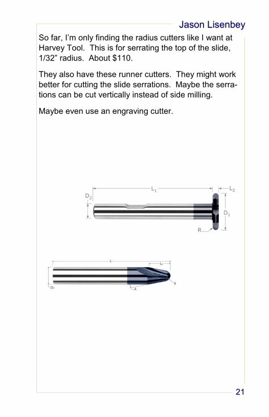
So far, I’m only finding the radius cutters like I want at
Harvey Tool. This is for serrating the top of the slide,
1/32” radius. About $110.
They also have these runner cutters. They might work
better for cutting the slide serrations. Maybe the serra-
tions can be cut vertically instead of side milling.
Maybe even use an engraving cutter.
Project Limited 10
22
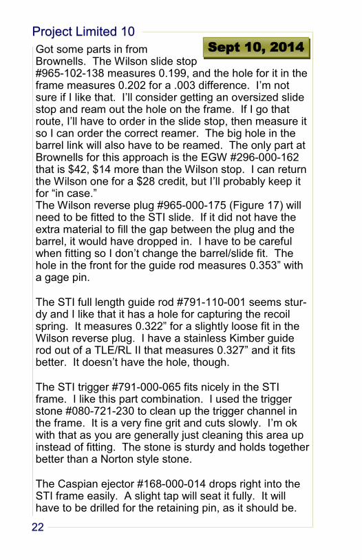
Got some parts in from Brownells. The Wilson slide stop #965-102-138 measures 0.199, and the hole for it in the frame measures 0.202 for a .003 difference. I’m not sure if I like that. I’ll consider getting an oversized slide stop and ream out the hole on the frame. If I go that route, I’ll have to order in the slide stop, then measure it so I can order the correct reamer. The big hole in the barrel link will also have to be reamed. The only part at Brownells for this approach is the EGW #296-000-162 that is $42, $14 more than the Wilson stop. I can return the Wilson one for a $28 credit, but I’ll probably keep it for “in case.” The Wilson reverse plug #965-000-175 (Figure 17) will need to be fitted to the STI slide. If it did not have the extra material to fill the gap between the plug and the barrel, it would have dropped in. I have to be careful when fitting so I don’t change the barrel/slide fit. The hole in the front for the guide rod measures 0.353” with a gage pin.
The STI full length guide rod #791-110-001 seems stur-dy and I like that it has a hole for capturing the recoil spring. It measures 0.322” for a slightly loose fit in the Wilson reverse plug. I have a stainless Kimber guide rod out of a TLE/RL II that measures 0.327” and it fits better. It doesn’t have the hole, though.
The STI trigger #791-000-065 fits nicely in the STI frame. I like this part combination. I used the trigger stone #080-721-230 to clean up the trigger channel in the frame. It is a very fine grit and cuts slowly. I’m ok with that as you are generally just cleaning this area up instead of fitting. The stone is sturdy and holds together better than a Norton style stone.
The Caspian ejector #168-000-014 drops right into the STI frame easily. A slight tap will seat it fully. It will have to be drilled for the retaining pin, as it should be.
Sept 10, 2014
Jason Lisenbey
23
No foreseen issues.
The Wilson barrel link kit #965-142-000 has 5 links, siz-es 1 – 5. I probably will only need #3. The links fit into the barrel easily. The holes for the link pin measure 0.155 – 0.157”. The link pin #965-011-051 measures 0.155”. The hole in the barrel bottom lugs for the link pin measures 0.151”. I need to get a reamer to fit these. I want the hole to be 0.155” for a nice press fit. Enco has an Interstate reamer #319-0747 for $14. The holes for the slide stop measure 0.201 – 0.204”. I will probably only need the #3 link, but this assortment co-vers the gamut of sizes. The left overs will be good to have lying in the tool box.
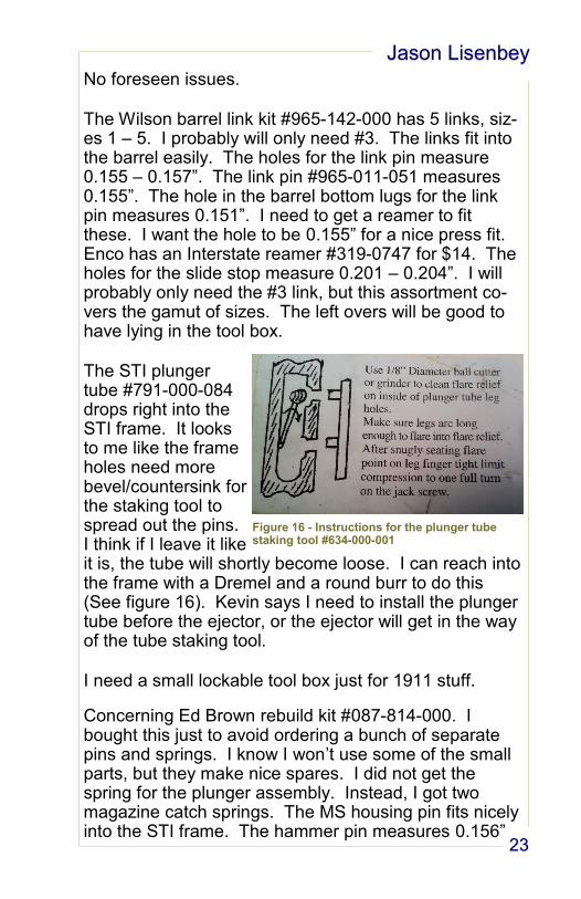
The STI plunger tube #791-000-084 drops right into the STI frame. It looks to me like the frame holes need more bevel/countersink for the staking tool to spread out the pins. I think if I leave it like it is, the tube will shortly become loose. I can reach into the frame with a Dremel and a round burr to do this (See figure 16). Kevin says I need to install the plunger tube before the ejector, or the ejector will get in the way of the tube staking tool.
I need a small lockable tool box just for 1911 stuff.
Concerning Ed Brown rebuild kit #087-814-000. I bought this just to avoid ordering a bunch of separate pins and springs. I know I won’t use some of the small parts, but they make nice spares. I did not get the spring for the plunger assembly. Instead, I got two magazine catch springs. The MS housing pin fits nicely into the STI frame. The hammer pin measures 0.156”
Figure 16 - Instructions for the plunger tube staking tool #634-000-001
Project Limited 10
24
and the hole in the frame is 0.154”. The sear pin measures 0.109” and the hole in the frame is 0.107”. I already have 0.157” and 0.110” reamers for these. The pins in the kit are not oversized, but the frame holes un-dersized (a good thing). This came with a link pin, so I didn’t need to get the one above.
The hole in the frame for the safety is 0.157”.
The barrel holder #080-711-100 holds the barrel in the locked position tightly (according to my fingers). I think it will work ok for lug cutting. I seems easy to knock loose, so I wouldn’t trust it to replace the slide fixture I’ve been working on. There’s no way it holds up to a milling machine. The slide still fits on the frame with the holder in position.
The lug cutter #080-000-063 seems awesomely made. We’ll see if it’s worth the $50. The lug cutter handle #080-000-058 also comes with a pilot bushing to hold the other side of the cutter straight in the hole. Overall totally happy with the lug cutting parts. The other two pieces to the kit (which I didn’t get) are a waste.
According to the Brownells instructions, I need to have
the thumb safety before fitting the lugs. You cut the
lugs until the safety goes into the notch in the slide. I
suppose I can use an old safety, but I prefer to use the
one that will go on the gun.
I’m saving all of the little Ziploc bags that the parts came
in. They’ll be handy later for small parts.
I’m going to go ahead and order the slide stop #296-000-162, and the safety #965-600-106 (oversize pin). When I get them I’ll measure the pins to order reamers. I’ll order from home as I don’t trust the internet right now here at school.
Jason Lisenbey
25
Yesterday I made a Brownells
order. I got an EGW slide stop
#296-000-162, with a 0.203 pin. When it comes in I’ll
order a reamer to fit it to the frame. I got a STI grip
safety #791-107-100 because it was cheap, and Wilson
safety #965-600-106 because I like a wide safety and it
was cheaper. The thumb safety is supposed to have a
0.002 oversized pin, if that’s true I’ll have to get a ream-
er for that, too.
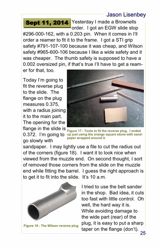
Today I’m going to
fit the reverse plug
to the slide. The
flange on the plug
measures 0.375,
with a radius joining
it to the main part.
The opening for the
flange in the slide is
0.372. I’m going to
go slowly with
sandpaper. I may lightly use a file to cut the radius out
of the corners (figure 18). I want it to look nice when
viewed from the muzzle end. On second thought, I sort
of removed those corners from the slide on the muzzle
end while fitting the barrel. I guess the right approach is
to get it to fit into the slide. It’s 10 a.m.
I tried to use the belt sander
in the shop. Bad idea, it cuts
too fast with little control. Oh
well, the hard way it is.
While avoiding damage to
the wide part (rear) of the
plug, it is easy to put a sharp
taper on the flange (don’t).
Sept 11, 2014
Figure 17 - Tools to fit the reverse plug. I ended up just using the orange square stone with sand-paper wrapped around it.
Figure 18 - The Wilson reverse plug

Project Limited 10
26
11 a.m. and I got the plug to go all the way in. I spent
about 30 minutes on that part. Now I need to fit the bar-
rel to it. Okay, the barrel already fit a little snug and I
like it. I wonder if that is normal. I’m going to say that
this took about an hour. I polished the end of the plug
with sandpaper flattened on the shop surface plate.
I’m not really happy with the
finished product (Figure 19).
There is too many gaps. The
corners of the slide under the
barrel were rounded off too
much when fitting. I also don’t
like the gaps where the plug
flange meets the rounded part.
The slide is going to be blued
with the barrel and plug pol-
ished stainless. That should
hide the gaps somewhat.
I may like the
looks of the stain-
less Kimber guide
rod better, but not
the function. I
suppose I could
drill a hole in it
easy enough.
That is something
to decide when
final fitting.
Note: The guide
rod, recoil spring, and plug will have to go into the slide
as one unit, after the barrel goes in.
Figure 20 - The fitted reverse plug
Figure 19 - A nicely fitted reverse plug. It is slightly proud of the slide. That may minimize mistakes in fitting.
Jason Lisenbey
27
I think in the future, if I’m doing a
hybrid-type barrel and I want to
flat-top it, I should keep the top barrel rib really tight in
the slot in the barrel, then fit it after it is flat topped.
Now that I have fitted the rib to the slot, I’m afraid if I flat
-top it the gap between the barrel rib and slide with be
larger than it is now and become unsightly. At this
point, I think the best approach is to keep the slide the
original profile. I’ll order another barrel and slide to flat
top for the next project. That may be a good one to do
an Open gun project. I’m undecided.
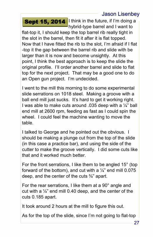
I went to the mill this morning to do some experimental
slide serrations on 1018 steel. Making a groove with a
ball end mill just sucks. It’s hard to get it working right.
I was able to make cuts around .035 deep with a ¼” ball
end mill at 2600 rpm, feeding as fast as I could spin the
wheel. I could feel the machine wanting to move the
table.
I talked to George and he pointed out the obvious. I
should be making a plunge cut from the top of the slide
(in this case a practice bar), and using the side of the
cutter to make the groove vertically. I did some cuts like
that and it worked much better.
For the front serrations, I like them to be angled 15° (top
forward of the bottom), and cut with a ¼” end mill 0.075
deep, and the center of the cuts ¾” apart.
For the rear serrations, I like them at a 90° angle and
cut with a ¼” end mill 0.40 deep, and the center of the
cuts 0.185 apart.
It took around 2 hours at the mill to figure this out.
As for the top of the slide, since I’m not going to flat-top
Sept 15, 2014
Project Limited 10
28
it, I think it will look good bead blasted on the top radius
with the sides polished (the slide blued). I think maybe
the front surface of the slide should be matte also to
conceal the gap between slide and reverse plug.
Since I’m not flat-topping the slide, I can cut the sights
now. I might as well wait until I get the front sight in and
do them at the same time.
Another option is to flat-top, but don’t go down all the
way past the barrel ribs. This way the side gap won’t
get wider. I think I like this idea best, but it’s best to
sleep on it. I keep changing my mind. I need to get the
new barrel holder fixture made ASAP.
Jason Lisenbey
29
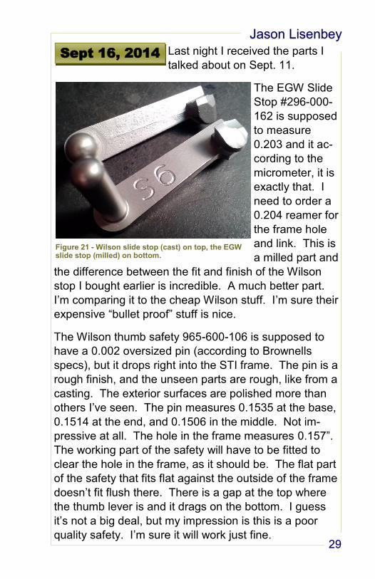
Last night I received the parts I
talked about on Sept. 11.
The EGW Slide
Stop #296-000-
162 is supposed
to measure
0.203 and it ac-
cording to the
micrometer, it is
exactly that. I
need to order a
0.204 reamer for
the frame hole
and link. This is
a milled part and
the difference between the fit and finish of the Wilson
stop I bought earlier is incredible. A much better part.
I’m comparing it to the cheap Wilson stuff. I’m sure their
expensive “bullet proof” stuff is nice.
The Wilson thumb safety 965-600-106 is supposed to
have a 0.002 oversized pin (according to Brownells
specs), but it drops right into the STI frame. The pin is a
rough finish, and the unseen parts are rough, like from a
casting. The exterior surfaces are polished more than
others I’ve seen. The pin measures 0.1535 at the base,
0.1514 at the end, and 0.1506 in the middle. Not im-
pressive at all. The hole in the frame measures 0.157”.
The working part of the safety will have to be fitted to
clear the hole in the frame, as it should be. The flat part
of the safety that fits flat against the outside of the frame
doesn’t fit flush there. There is a gap at the top where
the thumb lever is and it drags on the bottom. I guess
it’s not a big deal, but my impression is this is a poor
quality safety. I’m sure it will work just fine.
Sept 16, 2014
Figure 21 - Wilson slide stop (cast) on top, the EGW slide stop (milled) on bottom.
Project Limited 10
30
The STI grip safety 791-107-100 fits cleanly into the
frame after lightly knocking off the edges. The hole for
the safety pin measures 0.156”. It has a matte finish
identical to the STI frame. I’ll have to do a lot of polish-
ing here. Besides the extra polishing work, very little
blending with the frame is needed as it is almost perfect.
I think this is the benefit of using STI parts on the STI
frame.
I need to go ahead and order the reamer (0.204) for the
slide stop. I need the slide stop fitted before I can cut in
the barrel feet. I already have the sear pin reamer
(0.110) and the hammer pin reamer (0.156).
The difference between ordering cheap 1911 parts and
the more expensive ones is obvious here. It’s a good
idea to have examples of the parts in stock so the cus-
tomers can see the difference for themselves (even if
you are selling a complete gun).
I think a wire wheel finish on the stainless parts may
look good. That way the polishing doesn’t have to be
perfect on the odd-shaped parts (which is impossible).
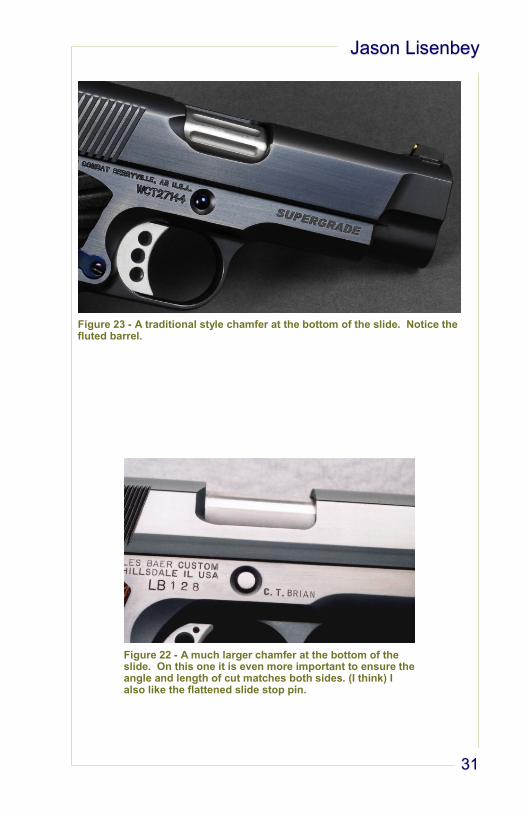
I want to do a 45 degree chamfer on the bottom slide
surface.
Two examples I like are on the next page.
Jason Lisenbey
31
Figure 23 - A traditional style chamfer at the bottom of the slide. Notice the fluted barrel.
Figure 22 - A much larger chamfer at the bottom of the slide. On this one it is even more important to ensure the angle and length of cut matches both sides. (I think) I also like the flattened slide stop pin.
Project Limited 10
32
This morning I installed the plunger tube. Very easy.
The first thing I did was bevel the inside holes for the
plunger tube staking posts. This allows the posts to ex-
pand more when staked, holding more securely (See
figure 16). I used the Gun Runners fixture 634-000-001
for staking and a Dremel bur for beveling the holes.
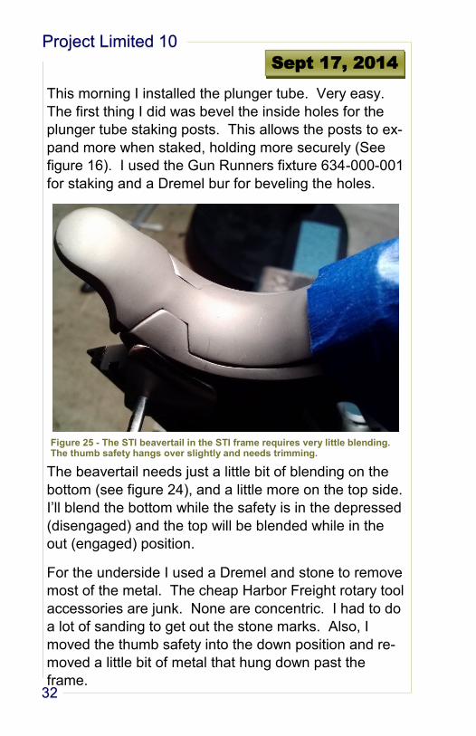
The beavertail needs just a little bit of blending on the
bottom (see figure 24), and a little more on the top side.
I’ll blend the bottom while the safety is in the depressed
(disengaged) and the top will be blended while in the
out (engaged) position.
For the underside I used a Dremel and stone to remove
most of the metal. The cheap Harbor Freight rotary tool
accessories are junk. None are concentric. I had to do
a lot of sanding to get out the stone marks. Also, I
moved the thumb safety into the down position and re-
moved a little bit of metal that hung down past the
frame.
Sept 17, 2014
Figure 25 - The STI beavertail in the STI frame requires very little blending. The thumb safety hangs over slightly and needs trimming.
Jason Lisenbey
33
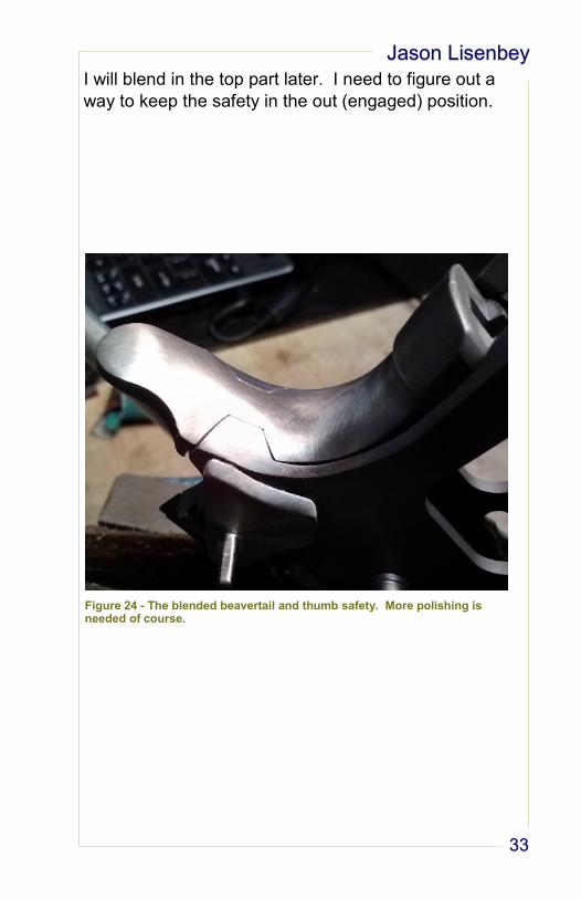
I will blend in the top part later. I need to figure out a
way to keep the safety in the out (engaged) position.
Figure 24 - The blended beavertail and thumb safety. More polishing is needed of course.
Project Limited 10
34
Today, I re-made the barrel hold-
er fixture. It’s much better this
time out of aluminum. I’m still having trouble getting the
slot for the barrel feet just right, but it’s not bad. The
slot needs to be wide enough to get the barrel through
easily, but any extra space allows the hybrid-type barrel
to tilt slightly when tightened down. This will make the
barrel rib and the slide slightly uneven after flat-topping.
I think the best solution is to use shim stock to wedge
the barrel rib into the center of the slot in the slide. You
can mill off the extra shim when you flat-top the slide
and barrel.
It took around six hours in the shop to mill the first part
of the fixture. There is a second part to be done later. I
made some changes to the print on the fly, and I need
to input the changes into the CAD program.
Note: Stop buying cheap tooling. I bought a 1” 2-flute
end mill and 1” end mill holder from Shar’s. The end
mill flutes were uneven and made a crappy cut. The
holder wouldn’t stay tight in the mill. The end mill fell
out of the mill and hit the floor while it was spinning at
1000 rpm.
Sept 18, 2014
Jason Lisenbey
35
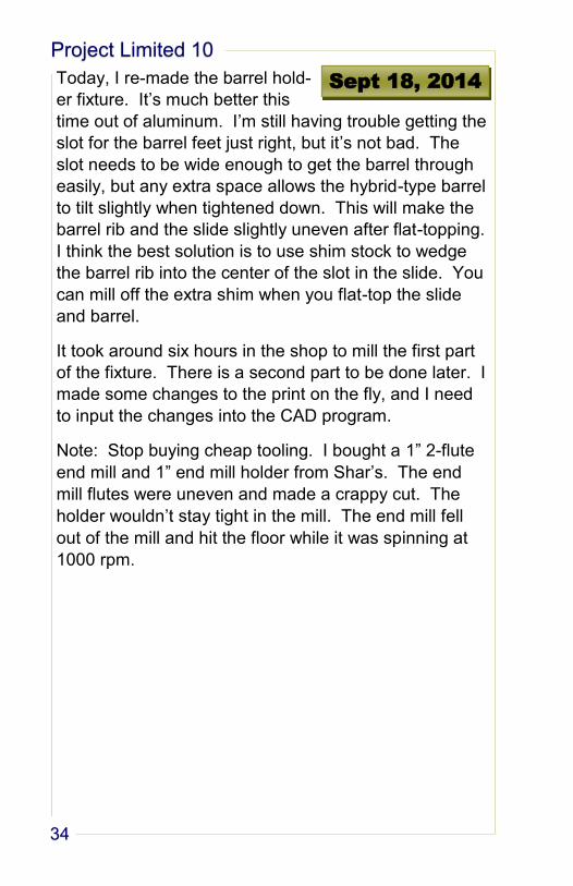
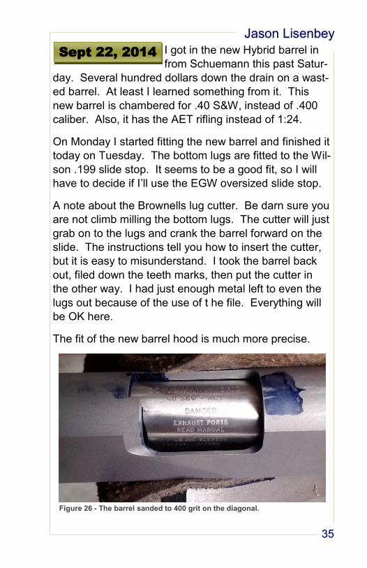
I got in the new Hybrid barrel in
from Schuemann this past Satur-
day. Several hundred dollars down the drain on a wast-
ed barrel. At least I learned something from it. This
new barrel is chambered for .40 S&W, instead of .400
caliber. Also, it has the AET rifling instead of 1:24.
On Monday I started fitting the new barrel and finished it
today on Tuesday. The bottom lugs are fitted to the Wil-
son .199 slide stop. It seems to be a good fit, so I will
have to decide if I’ll use the EGW oversized slide stop.
A note about the Brownells lug cutter. Be darn sure you
are not climb milling the bottom lugs. The cutter will just
grab on to the lugs and crank the barrel forward on the
slide. The instructions tell you how to insert the cutter,
but it is easy to misunderstand. I took the barrel back
out, filed down the teeth marks, then put the cutter in
the other way. I had just enough metal left to even the
lugs out because of the use of t he file. Everything will
be OK here.
The fit of the new barrel hood is much more precise.
Sept 22, 2014
Figure 26 - The barrel sanded to 400 grit on the diagonal.
Project Limited 10
36
There is about .003 - .004 gap between breech and
hood. It looks good and even. The top lug engagement
is .045 - .050. This is hard to get consistent measure-
ments on, but I didn’t get a measurement less
than .045, which is Schuemann’s recommended mini-
mum.
For now, I have the file marks in the barrel sanded out
with 220 grit on a diagonal. The part of the barrel ex-
posed in the ejection port, I sanded to 400 grit on the
diagonal. I looks ok for now. The barrel seemed awful-
ly easy to sand.
I reamed out the hole in the barrel bottom lugs to .156.
It came with the hole for the link pin sized at .152. The
pin I’m using is .1555, and I have to lightly tap it home
with a hammer. The link did not want to rotate freely at
first, and I was afraid that I reamed the hole poorly
somehow. I think it may have been burrs, as the link
moved much easier later on.
I assembled the frame, slide, barrel, link, and slide stop;
then checked the operation. The assembly seemed to
operate just ok. The barrel wasn’t quite a slick up and
down during lock-up, but it may just be the sticky link pin
issue. I’m not going to worry about it yet. It may not be
a problem later.
Crowning the barrel should be an easy project to do to-
morrow. At least I have a spare barrel to practice on
first. I need to hold off on blending the top of the bea-
vertail until I am sure the barrel feet are fitted correctly,
as that will change the slide alignment.
Jason Lisenbey
37
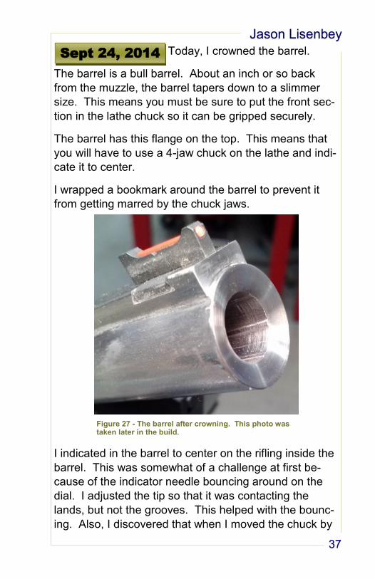
Today, I crowned the barrel.
The barrel is a bull barrel. About an inch or so back
from the muzzle, the barrel tapers down to a slimmer
size. This means you must be sure to put the front sec-
tion in the lathe chuck so it can be gripped securely.
The barrel has this flange on the top. This means that
you will have to use a 4-jaw chuck on the lathe and indi-
cate it to center.
I wrapped a bookmark around the barrel to prevent it
from getting marred by the chuck jaws.
I indicated in the barrel to center on the rifling inside the
barrel. This was somewhat of a challenge at first be-
cause of the indicator needle bouncing around on the
dial. I adjusted the tip so that it was contacting the
lands, but not the grooves. This helped with the bounc-
ing. Also, I discovered that when I moved the chuck by
Sept 24, 2014
Figure 27 - The barrel after crowning. This photo was taken later in the build.
Project Limited 10
38
hand back and forth to read the indicator, it was easier
to read when done quickly. This may be something
unique to me.
I practiced the crown with the 1st barrel, the one I decid-
ed not to use. On this one, I did the crown like I would
on a rifle. I cut out the rifling a little bit at the muzzle.
This didn’t look right and decided to not do this on the
actual barrel. The angle is about 25 degrees and looks
right.
You can see in the photo some scratches on the rifling
inside the muzzle. I think this may have been cause by
sandpaper when polishing. I didn’t get a tool inside the
barrel like that. This looks bad and should be avoided
on future barrel crowns.
Jason Lisenbey
39
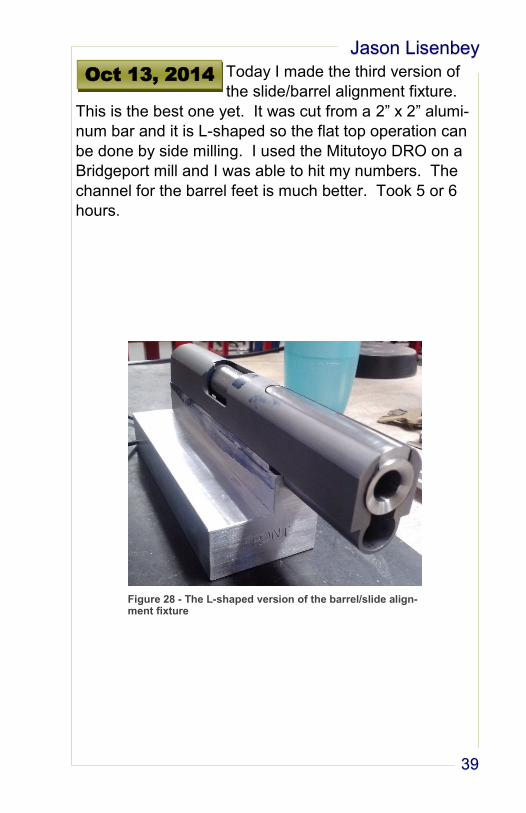
Today I made the third version of
the slide/barrel alignment fixture.
This is the best one yet. It was cut from a 2” x 2” alumi-
num bar and it is L-shaped so the flat top operation can
be done by side milling. I used the Mitutoyo DRO on a
Bridgeport mill and I was able to hit my numbers. The
channel for the barrel feet is much better. Took 5 or 6
hours.
Oct 13, 2014
Figure 28 - The L-shaped version of the barrel/slide align-ment fixture
Project Limited 10
40
Last night I received the parts from
Brownell’s order #10538114. I got
Nowlin grip screws and grip screw bushings in stainless.
I’ve used them before and they work well. They didn’t
send me the Wilson oversize magazine release and in-
stead sent a guide rod, so more to come there. I got a
hammer strut because the fire control parts I’ll order
from Dawson doesn’t have one. I got a blue Caspian
extractor 168-000-018. It needed to be tightened a little
for tension. Also, the slot in the extractor wasn’t big
enough for the firing pin stop after it was fitted. I had to
open up the slot with a pin file. The firing pin stop from
STI, 791-112-001, was not a drop in fit for the STI slide,
but was easily fitted with a bench stone. The firing pin
from Caspian is a 9mm size and worked well.
I also got a Wolff variable power spring pack for 1911s.
It contains different weight recoil springs. I’ll try the dif-
ferent springs to see which works best. The Dawson
light speed fire control parts has a reduced power main
spring and a light weight hammer. I’m thinking those
two offset
and I’ll need
a lighter re-
coil spring
because of
the slot cut in
the slide. I
guess we’ll
see.
Oct 15, 2014
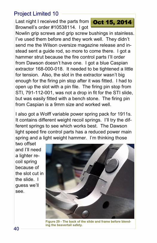
Figure 29 - The back of the slide and frame before blend-ing the beavertail safety.
Jason Lisenbey
41
This morning I will blend the top of
the grip safety to the frame and
slide. Yesterday I fitted the extractor, so it can be
blended in also. The ejector has been installed, so it
can be part of the blending.
I have noticed that the right side pin hole for the grip
safety needs to be chamfered. Maybe the sear and
hammer pins will have to be done the same way to
match.
I used a Dremel with a sanding drum to do the blending.
At first, I used a rough grit drum, probably 80-120. I
then switched to a 220 sanding drum. After that, I sort
of played around by wrapping sandpaper around the
rubber sanding arbor. I used 220 then 400 grit to get
what you see in Figure 29. What doesn’t show in the
photo is the waviness left by the Dremel rotation. I may
have to polish by hand to get rid of the waviness. This
is as far as I will go for now. I takes 30 minutes at the
most.
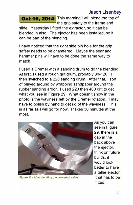
As you can
see in Figure
29, there is a
gap in the
back above
the ejector. I
think on future
builds, it
would look
better to have
a taller ejector
that has to be
fitted.
Oct 16, 2014
Figure 30 - After blending the beavertail safety.
Project Limited 10
42
Today I flat-topped the slide and
installed the rear sight.
Flat-Top
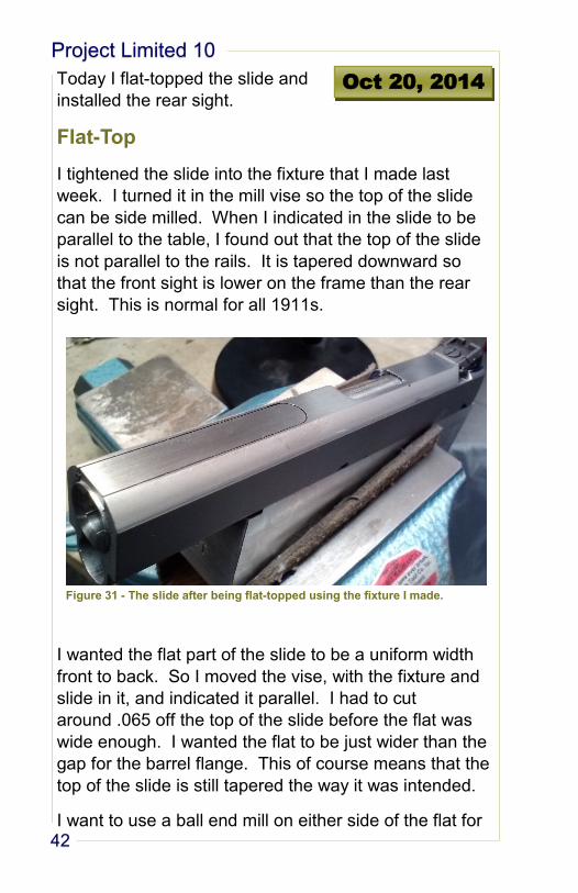
I tightened the slide into the fixture that I made last
week. I turned it in the mill vise so the top of the slide
can be side milled. When I indicated in the slide to be
parallel to the table, I found out that the top of the slide
is not parallel to the rails. It is tapered downward so
that the front sight is lower on the frame than the rear
sight. This is normal for all 1911s.
I wanted the flat part of the slide to be a uniform width
front to back. So I moved the vise, with the fixture and
slide in it, and indicated it parallel. I had to cut
around .065 off the top of the slide before the flat was
wide enough. I wanted the flat to be just wider than the
gap for the barrel flange. This of course means that the
top of the slide is still tapered the way it was intended.
I want to use a ball end mill on either side of the flat for
Oct 20, 2014
Figure 31 - The slide after being flat-topped using the fixture I made.
Jason Lisenbey
43
a nice look. Since the top of the slide is tapered, there
are two approaches that I can think of to get accurate
cuts.
First, orient the slide in the fixture the same way as be-
fore so that it can be side milled. Indicate everything
parallel. Figure out the depth (Z axis), lock it down and
make all the cuts by feeding along the X and using Y for
depth of cut.
Second, orient the slide and fixture vertical. There will
have to be some shimming done to get the flat top to
indicate level. If it is not level, the cuts will vary in width
from front to back. Maybe I can just stick it in the vise
off the bottom and tap it back and forth until it is level.
Again figure out the Z depth and make the cuts coming
in sideways.
If I do it the first way, I’ll have to modify the fixture so the
slide can be installed from front and back. That proba-
bly needs to be done anyway.
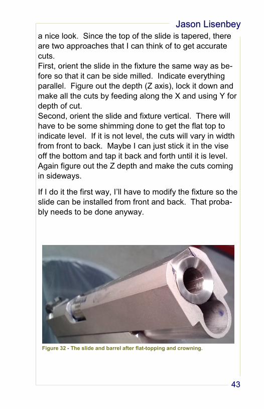
Figure 32 - The slide and barrel after flat-topping and crowning.
Project Limited 10
44
Rear Sight
The sight I installed is a Dawson precision, Novak-style,
adjustable sight, part number 024-022. It is designed to
install exactly like a Novak Lo-Mount sight. I couldn’t
find any instructions to install this in a slide that doesn’t
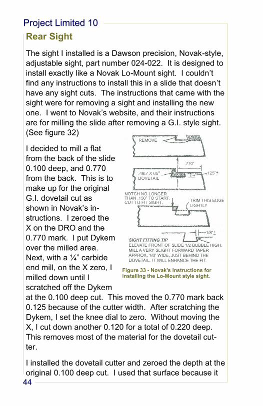
have any sight cuts. The instructions that came with the
sight were for removing a sight and installing the new
one. I went to Novak’s website, and their instructions
are for milling the slide after removing a G.I. style sight.
(See figure 32)
I decided to mill a flat
from the back of the slide
0.100 deep, and 0.770
from the back. This is to
make up for the original
G.I. dovetail cut as
shown in Novak’s in-
structions. I zeroed the
X on the DRO and the
0.770 mark. I put Dykem
over the milled area.
Next, with a ¼” carbide
end mill, on the X zero, I
milled down until I
scratched off the Dykem
at the 0.100 deep cut. This moved the 0.770 mark back
0.125 because of the cutter width. After scratching the
Dykem, I set the knee dial to zero. Without moving the
X, I cut down another 0.120 for a total of 0.220 deep.
This removes most of the material for the dovetail cut-
ter.
I installed the dovetail cutter and zeroed the depth at the
original 0.100 deep cut. I used that surface because it
Figure 33 - Novak's instructions for installing the Lo-Mount style sight.
Jason Lisenbey
45
is flat and easy to see what I was doing. Take the cutter
back off the slide and move the X to the zero previously
established on the DRO. Now you can move the table
up so the cutter is 0.125 deep. Cut through the slot
made with the ¼” end mill. The dovetail cutter I was us-
ing is 0.330 x 65 degrees. The dovetail on the sight is
0.495. So, once I was through, I needed to cut 0.0825
more on either side. This is easy to do with the use of
the DRO. I had to make the slot about 0.497 to get the
sight in.
The above steps are what I did. That doesn’t mean it
was the right way to do it.
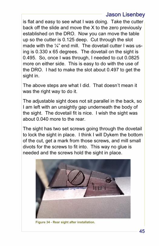
The adjustable sight does not sit parallel in the back, so
I am left with an unsightly gap underneath the body of
the sight. The dovetail fit is nice. I wish the sight was
about 0.040 more to the rear.
The sight has two set screws going through the dovetail
to lock the sight in place. I think I will Dykem the bottom
of the cut, get a mark from those screws, and mill small
divots for the screws to fit into. This way no glue is
needed and the screws hold the sight in place.
Figure 34 - Rear sight after installation.
Project Limited 10
46
It’s not likely that I will be able to
get into the shop today, so I will
talk about the sight I installed yesterday.
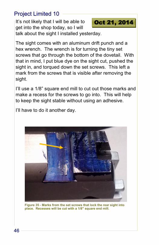
The sight comes with an aluminum drift punch and a
hex wrench. The wrench is for turning the tiny set
screws that go through the bottom of the dovetail. With
that in mind, I put blue dye on the sight cut, pushed the
sight in, and torqued down the set screws. This left a
mark from the screws that is visible after removing the
sight.
I’ll use a 1/8” square end mill to cut out those marks and
make a recess for the screws to go into. This will help
to keep the sight stable without using an adhesive.
I’ll have to do it another day.
Oct 21, 2014
Figure 35 - Marks from the set screws that lock the rear sight into place. Recesses will be cut with a 1/8" square end mill.
Jason Lisenbey
47
Magazine Release
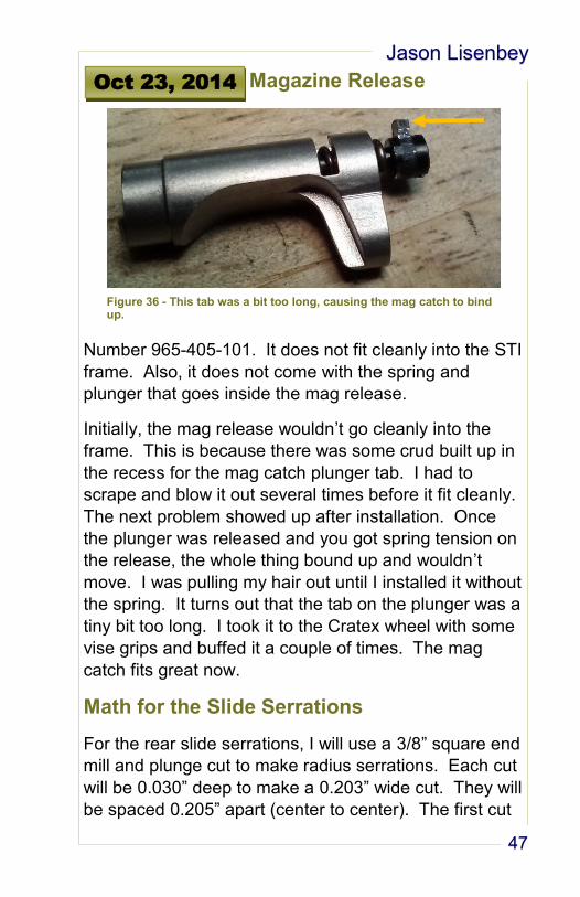
Number 965-405-101. It does not fit cleanly into the STI
frame. Also, it does not come with the spring and
plunger that goes inside the mag release.
Initially, the mag release wouldn’t go cleanly into the
frame. This is because there was some crud built up in
the recess for the mag catch plunger tab. I had to
scrape and blow it out several times before it fit cleanly.
The next problem showed up after installation. Once
the plunger was released and you got spring tension on
the release, the whole thing bound up and wouldn’t
move. I was pulling my hair out until I installed it without
the spring. It turns out that the tab on the plunger was a
tiny bit too long. I took it to the Cratex wheel with some
vise grips and buffed it a couple of times. The mag
catch fits great now.
Math for the Slide Serrations
For the rear slide serrations, I will use a 3/8” square end
mill and plunge cut to make radius serrations. Each cut
will be 0.030” deep to make a 0.203” wide cut. They will
be spaced 0.205” apart (center to center). The first cut
Oct 23, 2014
Figure 36 - This tab was a bit too long, causing the mag catch to bind up.
Project Limited 10
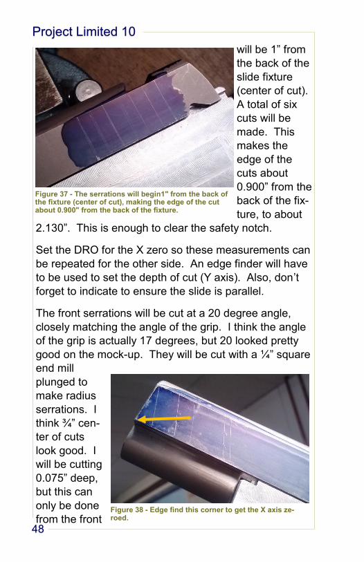
48
will be 1” from
the back of the
slide fixture
(center of cut).
A total of six
cuts will be
made. This
makes the
edge of the
cuts about
0.900” from the
back of the fix-
ture, to about
2.130”. This is enough to clear the safety notch.
Set the DRO for the X zero so these measurements can
be repeated for the other side. An edge finder will have
to be used to set the depth of cut (Y axis). Also, don’t
forget to indicate to ensure the slide is parallel.
The front serrations will be cut at a 20 degree angle,
closely matching the angle of the grip. I think the angle
of the grip is actually 17 degrees, but 20 looked pretty
good on the mock-up. They will be cut with a ¼” square
end mill
plunged to
make radius
serrations. I
think ¾” cen-
ter of cuts
look good. I
will be cutting
0.075” deep,
but this can
only be done
from the front
Figure 37 - The serrations will begin1" from the back of the fixture (center of cut), making the edge of the cut about 0.900" from the back of the fixture.
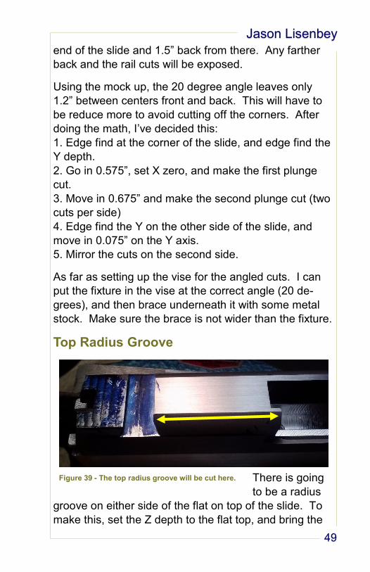
Figure 38 - Edge find this corner to get the X axis ze-roed.
Jason Lisenbey
49
end of the slide and 1.5” back from there. Any farther
back and the rail cuts will be exposed.
Using the mock up, the 20 degree angle leaves only
1.2” between centers front and back. This will have to
be reduce more to avoid cutting off the corners. After
doing the math, I’ve decided this:
1. Edge find at the corner of the slide, and edge find the
Y depth.
2. Go in 0.575”, set X zero, and make the first plunge
cut.
3. Move in 0.675” and make the second plunge cut (two
cuts per side)
4. Edge find the Y on the other side of the slide, and
move in 0.075” on the Y axis.
5. Mirror the cuts on the second side.
As far as setting up the vise for the angled cuts. I can
put the fixture in the vise at the correct angle (20 de-
grees), and then brace underneath it with some metal
stock. Make sure the brace is not wider than the fixture.
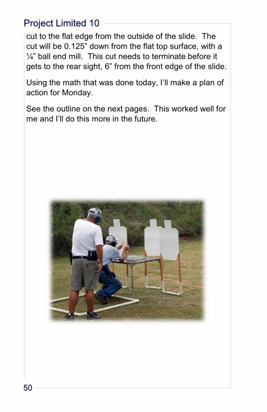
Top Radius Groove
There is going
to be a radius
groove on either side of the flat on top of the slide. To
make this, set the Z depth to the flat top, and bring the
Figure 39 - The top radius groove will be cut here.
Project Limited 10
50
cut to the flat edge from the outside of the slide. The
cut will be 0.125” down from the flat top surface, with a
¼” ball end mill. This cut needs to terminate before it
gets to the rear sight, 6” from the front edge of the slide.
Using the math that was done today, I’ll make a plan of
action for Monday.
See the outline on the next pages. This worked well for
me and I’ll do this more in the future.
Jason Lisenbey
51
Outline for Monday
INITIAL SET UP
1. Install the slide onto the fixture. Use an aluminum rod in place of the barrel to add rigidity to the front of the slide in the fixture.
2. Put the fixture in the mill vise on parallels tall enough that when making the slide serration cuts there is enough clearance for the end mill.
3. Indicate in the flat top. It should be perpendicular to the spindle and parallel to the table. Shims underneath the fixture at the front end may be needed.
4. Indicate in the side of the slide. This ensures the top grooves will be parallel to the flat top cut.
5. Check that the top of the slide is still good.
REAR SIGHT
1. Install a 1/8” carbide end mill. Set RPM at 4800 (or maximum).
2. Eyeball the alignment of the end mill over the Dykem marks. A light touch off will ensure correct alignment.
3. Cut out the marks left in the Dykem by the set screws. Go about 0.025” deep.
4. Test fit the rear sight before changing this set up. The sight should be solidly in place when the set screws are lightly tightened.
5. Top Radius Groove
6. Edge finder to locate the muzzle end of the slide. Set this as X zero on the DRO.
7. Edge finder to locate one side of the slide. Set this as Y zero on the DRO.
8. Install a ¼” carbide ball end mill. Set RPM at 3000.
9. Using a shim, set Z zero on the knee dial to the top of the slide.
10. Move the end mill out of the way to the side of the slide previously indicated.
11. Raise the table 0.125”. No need to account for the thickness of the shim.
12. Make light cuts coming in sideways until the cut almost touches the edge of the flat-top cut. You will go 6” from the front of the slide. This will nicely terminate the cut before the rear sight.
13. When it is how you like it, write down the Y measurement that is on the DRO.
14. Edge finder the other side of the slide.
15. Make the grove on the other side of the slide, using the same Y measurement to repeat the cut.
Project Limited 10
52
REAR SERRATIONS
1. Take out the shims from underneath the fixture. This will ensure the rear serra-tions are perpendicular to the bottom edge of the slide.
2. Indicate the sides of the slide in the area the serrations will go. This will ensure the cuts are a uniform depth.
3. Edge finder the edge of the fixture behind the back of the slide. Set this as X zero on the DRO.
4. Edge finder to locate one side of the slide, and set this as Y zero on the DRO. Be sure to account for the thickness of the edge finder.
5. Install a 3/8” carbide square end mill. Set the RPM at 1600.
6. The Y depth of cut right now would be 0.1875 (3/8” cutter) if we don’t move the Y axis. Move the spindle away from the slide 0.1575 to get a 0.030 depth of cut.
7. Move the slide back so the first cut will be 1” from the back of the fixture, or 1” on the DRO.
8. After making the first cut, move forward 0.205” and make the next cut. Keep this spacing and make a total of 6 cuts. The DRO should read 2.025” after the 6th cut.
9. Repeat by edge finding the other side and re-setting the Y zero and doing the math in step 6. Do not change the X zero so the cuts will be mirrored on the other side.
FRONT SERRATIONS
1. Move the fixture in the vise so the front of the slide is raised up 20 degrees. Use some metal stock to shim up the vise to hold it as rigidly as possible.
2. We are only making to cuts on each side, so indicating in the sides of the slide is probably not necessary.
3. Edge find to the front corner of the slide and set this as X zero on the DRO.
4. Edge finder one side of the slide and set this as Y zero on the DRO.
5. Install a ¼” carbide square end mill (long). Set the RPM at 2400.
6. The Y depth of cut right now would be 0.125 (1/4” cutter) if we don’t move the Y axis. Move the spindle away from the slide 0.050 to get a 0.075 depth of cut.
7. Move the slide forward so the first cut will be .575” from the front corner of the slide, or 0.575” on the DRO.
8. After making the first cut, move forward 0.675” and make the next cut, or 1.250” on the DRO.
9. Repeat by edge finding the other side and re-setting the Y zero and doing the math in step 6. Do not change the X zero so the cuts will be mirrored on the other side.
Jason Lisenbey
53
Today I made all of the slide cuts
that I had outlined above. It took
around 3.5 hours. It went pretty smoothly since I had
made the outline. I didn’t spend too much time calculat-
ing and second guessing. I’ll make my notes according
to the section in the outline.
Initial Set Up
I already had the slide installed on the fixture with the
aluminum rod in place. It took a bookmark and a piece
of sandpaper to get the top relatively level, no big deal.
When I indicated the sides of the slide to ensure they
were straight, it was obvious the slide was not milled
flat, at least it’s not flat anymore. The right side of the
slide was ok until I moved forward of the area cut out for
the barrel flange. There it was bent outward. I indicat-
ed the flat area behind this. When I checked the other
side, it was dished out in the middle. Oh well, I did the
best I could.
Rear Sight
Easy enough. I didn’t measure the depth, just eyeballed
it. I should have zeroed the Z axis and moved the table
up to measure the depth. This will ensure the cuts
aren’t accidentally made too deep (I got lucky).
Top Radius Groove
Due to the indicating problem noted above, I was wor-
ried about this cut being uneven. I was obvious when
the cut was pretty shallow, but it’s not noticeable after
going the full depth. I zeroed the cutter on the flat top
with a bookmark shim. The table was cranked up
0.125” without accounting for the shim.
Oct 27, 2014
Project Limited 10
54
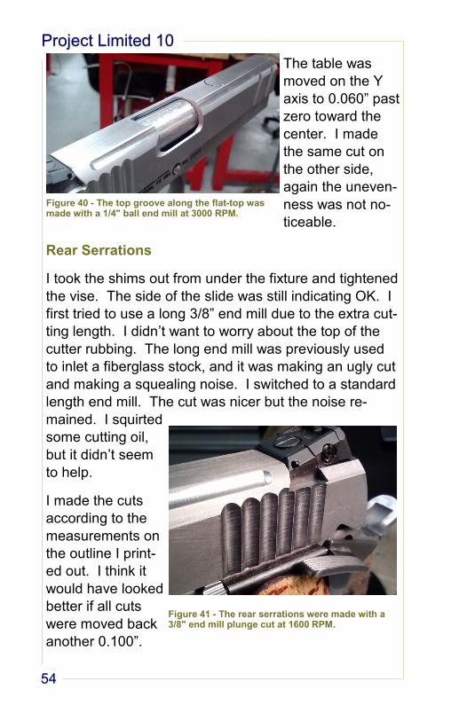
The table was
moved on the Y
axis to 0.060” past
zero toward the
center. I made
the same cut on
the other side,
again the uneven-
ness was not no-
ticeable.
Rear Serrations
I took the shims out from under the fixture and tightened
the vise. The side of the slide was still indicating OK. I
first tried to use a long 3/8” end mill due to the extra cut-
ting length. I didn’t want to worry about the top of the
cutter rubbing. The long end mill was previously used
to inlet a fiberglass stock, and it was making an ugly cut
and making a squealing noise. I switched to a standard
length end mill. The cut was nicer but the noise re-
mained. I squirted
some cutting oil,
but it didn’t seem
to help.
I made the cuts
according to the
measurements on
the outline I print-
ed out. I think it
would have looked
better if all cuts
were moved back
another 0.100”.
Figure 40 - The top groove along the flat-top was made with a 1/4" ball end mill at 3000 RPM.
Figure 41 - The rear serrations were made with a 3/8" end mill plunge cut at 1600 RPM.
Jason Lisenbey
55
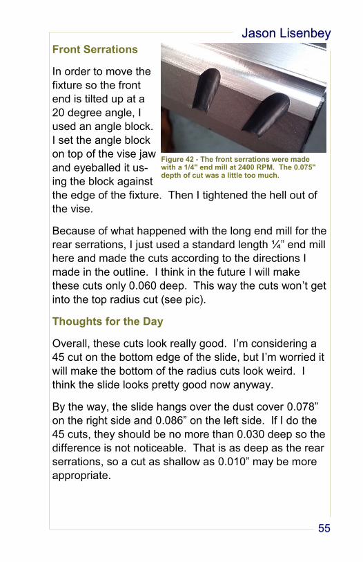
Front Serrations
In order to move the
fixture so the front
end is tilted up at a
20 degree angle, I
used an angle block.
I set the angle block
on top of the vise jaw
and eyeballed it us-
ing the block against
the edge of the fixture. Then I tightened the hell out of
the vise.
Because of what happened with the long end mill for the
rear serrations, I just used a standard length ¼” end mill
here and made the cuts according to the directions I
made in the outline. I think in the future I will make
these cuts only 0.060 deep. This way the cuts won’t get
into the top radius cut (see pic).
Thoughts for the Day
Overall, these cuts look really good. I’m considering a
45 cut on the bottom edge of the slide, but I’m worried it
will make the bottom of the radius cuts look weird. I
think the slide looks pretty good now anyway.
By the way, the slide hangs over the dust cover 0.078”
on the right side and 0.086” on the left side. If I do the
45 cuts, they should be no more than 0.030 deep so the
difference is not noticeable. That is as deep as the rear
serrations, so a cut as shallow as 0.010” may be more
appropriate.
Figure 42 - The front serrations were made with a 1/4" end mill at 2400 RPM. The 0.075" depth of cut was a little too much.
Project Limited 10
56
Figure 43 - So far, so good.
Jason Lisenbey
57
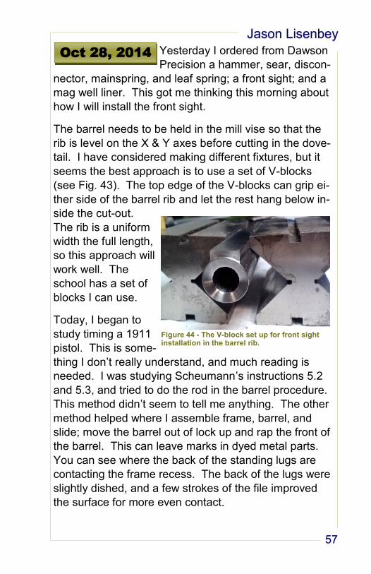
Yesterday I ordered from Dawson
Precision a hammer, sear, discon-
nector, mainspring, and leaf spring; a front sight; and a
mag well liner. This got me thinking this morning about
how I will install the front sight.
The barrel needs to be held in the mill vise so that the
rib is level on the X & Y axes before cutting in the dove-
tail. I have considered making different fixtures, but it
seems the best approach is to use a set of V-blocks
(see Fig. 43). The top edge of the V-blocks can grip ei-
ther side of the barrel rib and let the rest hang below in-
side the cut-out.
The rib is a uniform
width the full length,
so this approach will
work well. The
school has a set of
blocks I can use.
Today, I began to
study timing a 1911
pistol. This is some-
thing I don’t really understand, and much reading is
needed. I was studying Scheumann’s instructions 5.2
and 5.3, and tried to do the rod in the barrel procedure.
This method didn’t seem to tell me anything. The other
method helped where I assemble frame, barrel, and
slide; move the barrel out of lock up and rap the front of
the barrel. This can leave marks in dyed metal parts.
You can see where the back of the standing lugs are
contacting the frame recess. The back of the lugs were
slightly dished, and a few strokes of the file improved
the surface for more even contact.
Oct 28, 2014
Figure 44 - The V-block set up for front sight installation in the barrel rib.
Project Limited 10
58
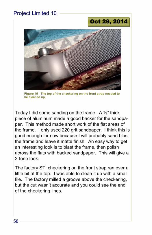
Today I did some sanding on the frame. A ½” thick
piece of aluminum made a good backer for the sandpa-
per. This method made short work of the flat areas of
the frame. I only used 220 grit sandpaper. I think this is
good enough for now because I will probably sand blast
the frame and leave it matte finish. An easy way to get
an interesting look is to blast the frame, then polish
across the flats with backed sandpaper. This will give a
2-tone look.
The factory STI checkering on the front strap ran over a
little bit at the top. I was able to clean it up with a small
file. The factory milled a groove above the checkering,
but the cut wasn’t accurate and you could see the end
of the checkering lines.
Oct 29, 2014
Figure 45 - The top of the checkering on the front strap needed to be cleaned up.
Jason Lisenbey
59
I used the V-block method de-
scribed Oct. 28 to install the front
sight on the barrel.
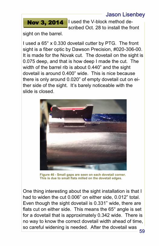
I used a 65° x 0.330 dovetail cutter by PTG. The front
sight is a fiber optic by Dawson Precision, #020-306-00.
It is made for the Novak cut. The dovetail on the sight is
0.075 deep, and that is how deep I made the cut. The
width of the barrel rib is about 0.440” and the sight
dovetail is around 0.400” wide. This is nice because
there is only around 0.020” of empty dovetail cut on ei-
ther side of the sight. It’s barely noticeable with the
slide is closed.
One thing interesting about the sight installation is that I
had to widen the cut 0.006” on either side, 0.012” total.
Even though the sight dovetail is 0.331” wide, there are
flats cut on either side. This means the 65° angle is set
for a dovetail that is approximately 0.342 wide. There is
no way to know the correct dovetail width ahead of time,
so careful widening is needed. After the dovetail was
Nov 3, 2014
Figure 46 - Small gaps are seen on each dovetail corner. This is due to small flats milled on the dovetail edges.
Project Limited 10
60
cut straight through with the cutter, I carefully widened it
0.001” on each side (using the DRO) until I was able to
get the sight started by hand. DP sights are made very
precise, so if you can get it started by hand, you will
most likely be able to easily tap it in place. I don’t think I
will pin it, just a little bit of Loctite will do.
You can see small gaps on either side of the dovetail in
the corners. This is because small flats are milled onto
either side of the dovetail. I don’t think they would be
seen on a normal slide installation, and it is not noticea-
ble here because the slot in the slide covers it up.
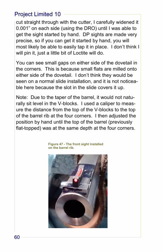
Note: Due to the taper of the barrel, it would not natu-
rally sit level in the V-blocks. I used a caliper to meas-
ure the distance from the top of the V-blocks to the top
of the barrel rib at the four corners. I then adjusted the
position by hand until the top of the barrel (previously
flat-topped) was at the same depth at the four corners.
Figure 47 - The front sight installed on the barrel rib.
Jason Lisenbey
61
Today I fitted and installed the
beavertail, hammer, sear, discon-
nector, and thumb safety.
The hammer, sear,
disconnector, sear
spring, and main-
spring all came in a
kit sold by Dawson
Precision. It’s called
the Lite Speed II
Trigger Group, #300-
112A ($130). On first
look, these seemed
to be very nice parts
because they are milled very precisely and the contact
points were already polished (nice). All edges were
nicely chamfered.
The hammer and sear pins would not quite fit into the
frame. You can hammer them in, but we don’t want that.
I already had a 0.110 and 0.156 reamers from the Infini-
ty project, so I used them on the frame so the pins
would drop in. I totally expected the trigger group to not
work correctly, as usual, but after installing them I had a
nice 4 ½ lb. trigger pull! I want to get this lighter for
competition purposes, but I was impressed with these
parts.
The beavertail is by STI, #791-107-100. It is mated with
an STI trigger, #791-000-065. Since I had already
blended the beavertail to the frame and slide, very little
fitting was needed. The tab that stops the trigger did
not need to be trimmed for length. I only needed to
make clearance underneath the tab. Around 10 strokes
with a fine file did the job. This beavertail is a rough fin-
Nov 4, 2014
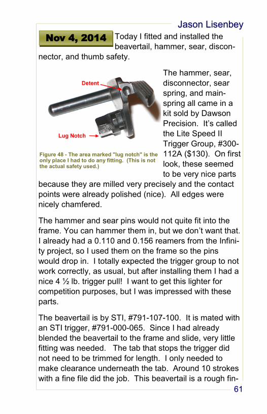
Figure 48 - The area marked "lug notch" is the only place I had to do any fitting. (This is not the actual safety used.)
Project Limited 10
62
ish so it will need a lot of polishing later, which would
have to be done anyway.
After the trigger components and the beavertail were
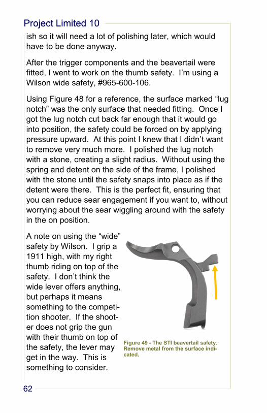
fitted, I went to work on the thumb safety. I’m using a
Wilson wide safety, #965-600-106.
Using Figure 48 for a reference, the surface marked “lug
notch” was the only surface that needed fitting. Once I
got the lug notch cut back far enough that it would go
into position, the safety could be forced on by applying
pressure upward. At this point I knew that I didn’t want
to remove very much more. I polished the lug notch
with a stone, creating a slight radius. Without using the
spring and detent on the side of the frame, I polished
with the stone until the safety snaps into place as if the
detent were there. This is the perfect fit, ensuring that
you can reduce sear engagement if you want to, without
worrying about the sear wiggling around with the safety
in the on position.
A note on using the “wide”
safety by Wilson. I grip a
1911 high, with my right
thumb riding on top of the
safety. I don’t think the
wide lever offers anything,
but perhaps it means
something to the competi-
tion shooter. If the shoot-
er does not grip the gun
with their thumb on top of
the safety, the lever may
get in the way. This is
something to consider.
Figure 49 - The STI beavertail safety. Remove metal from the surface indi-cated.
Jason Lisenbey
63
This morning I disassembled the
pistol in preparation for some met-
al polishing. While it is apart, I took the disconnector to
the Cratex wheel to get rid of those edges that stuck up
too far. We’ll see how it works after reassembly.
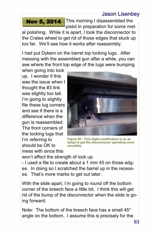
I had put Dykem on the barrel top locking lugs. After
messing with the assembled gun after a while, you can
see where the front top edge of the lugs were bumping
when going into lock
up. I wonder if this
was the issue when I
thought the #3 link
was slightly too tall.
I’m going to slightly
file these lug corners
and see if there is a
difference when the
gun is reassembled.
The front corners of
the locking lugs that
I’m referring to
should be OK to
mess with since this
won’t affect the strength of lock up.
- I used a file to create about a 1 mm 45 on those edg-
es. In doing so I scratched the barrel up in the recess-
es. That’s more marks to get out later.
With the slide apart, I’m going to round off the bottom
corner of the breech face a little bit. I think this will get
rid of the bump of the disconnector when the slide is go-
ing forward.
Note: The bottom of the breech face has a small 45°
angle on the bottom. I assume this is precisely for the
Nov 5, 2014
Figure 50 - This slight modification is an at-tempt to get the disconnector operating more smoothly.
Project Limited 10
64
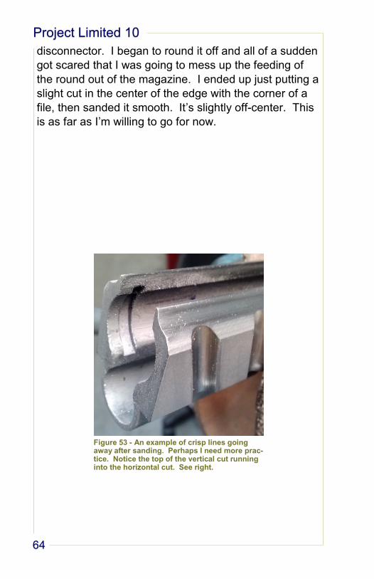
disconnector. I began to round it off and all of a sudden
got scared that I was going to mess up the feeding of
the round out of the magazine. I ended up just putting a
slight cut in the center of the edge with the corner of a
file, then sanded it smooth. It’s slightly off-center. This
is as far as I’m willing to go for now.
Figure 53 - An example of crisp lines going away after sanding. Perhaps I need more prac-tice. Notice the top of the vertical cut running into the horizontal cut. See right.
Jason Lisenbey
65
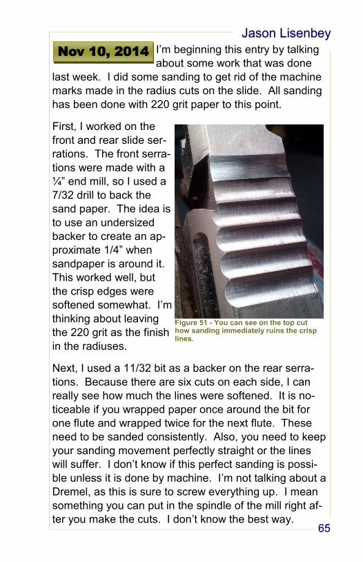
I’m beginning this entry by talking
about some work that was done
last week. I did some sanding to get rid of the machine
marks made in the radius cuts on the slide. All sanding
has been done with 220 grit paper to this point.
First, I worked on the
front and rear slide ser-
rations. The front serra-
tions were made with a
¼” end mill, so I used a
7/32 drill to back the
sand paper. The idea is
to use an undersized
backer to create an ap-
proximate 1/4” when
sandpaper is around it.
This worked well, but
the crisp edges were
softened somewhat. I’m
thinking about leaving
the 220 grit as the finish
in the radiuses.
Next, I used a 11/32 bit as a backer on the rear serra-
tions. Because there are six cuts on each side, I can
really see how much the lines were softened. It is no-
ticeable if you wrapped paper once around the bit for
one flute and wrapped twice for the next flute. These
need to be sanded consistently. Also, you need to keep
your sanding movement perfectly straight or the lines
will suffer. I don’t know if this perfect sanding is possi-
ble unless it is done by machine. I’m not talking about a
Dremel, as this is sure to screw everything up. I mean
something you can put in the spindle of the mill right af-
ter you make the cuts. I don’t know the best way.
Nov 10, 2014
Figure 51 - You can see on the top cut how sanding immediately ruins the crisp lines.
Project Limited 10
66
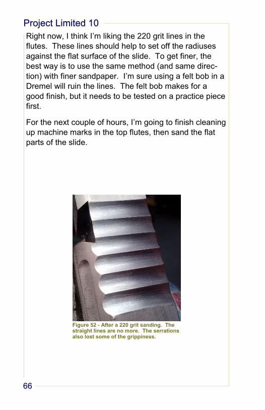
Right now, I think I’m liking the 220 grit lines in the
flutes. These lines should help to set off the radiuses
against the flat surface of the slide. To get finer, the
best way is to use the same method (and same direc-
tion) with finer sandpaper. I’m sure using a felt bob in a
Dremel will ruin the lines. The felt bob makes for a
good finish, but it needs to be tested on a practice piece
first.
For the next couple of hours, I’m going to finish cleaning
up machine marks in the top flutes, then sand the flat
parts of the slide.
Figure 52 - After a 220 grit sanding. The straight lines are no more. The serrations also lost some of the grippiness.
Jason Lisenbey
67
I’ve decided to not do the 45 de-
gree angle cut on the bottom of the
slide. I don’t think I would like how the bottom of the
front and rear serrations will look after being chamfered.
The disconnector is still giving a bump when the slide
goes forward. A little more shaping (I mean slightly) on
the back side top of the disconnector should help. I
don’t want to cut any more on the breech face. I worry
about feeding issues.
Nov 12, 2014
Project Limited 10
68
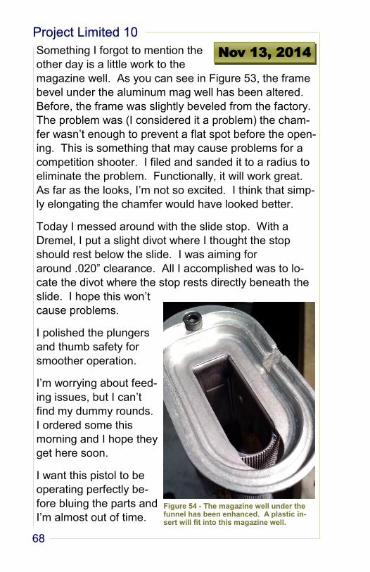
Something I forgot to mention the
other day is a little work to the
magazine well. As you can see in Figure 53, the frame
bevel under the aluminum mag well has been altered.
Before, the frame was slightly beveled from the factory.
The problem was (I considered it a problem) the cham-
fer wasn’t enough to prevent a flat spot before the open-
ing. This is something that may cause problems for a
competition shooter. I filed and sanded it to a radius to
eliminate the problem. Functionally, it will work great.
As far as the looks, I’m not so excited. I think that simp-
ly elongating the chamfer would have looked better.
Today I messed around with the slide stop. With a
Dremel, I put a slight divot where I thought the stop
should rest below the slide. I was aiming for
around .020” clearance. All I accomplished was to lo-
cate the divot where the stop rests directly beneath the
slide. I hope this won’t
cause problems.
I polished the plungers
and thumb safety for
smoother operation.
I’m worrying about feed-
ing issues, but I can’t
find my dummy rounds.
I ordered some this
morning and I hope they
get here soon.
I want this pistol to be
operating perfectly be-
fore bluing the parts and
I’m almost out of time.
Nov 13, 2014
Figure 54 - The magazine well under the funnel has been enhanced. A plastic in-sert will fit into this magazine well.
Jason Lisenbey
69
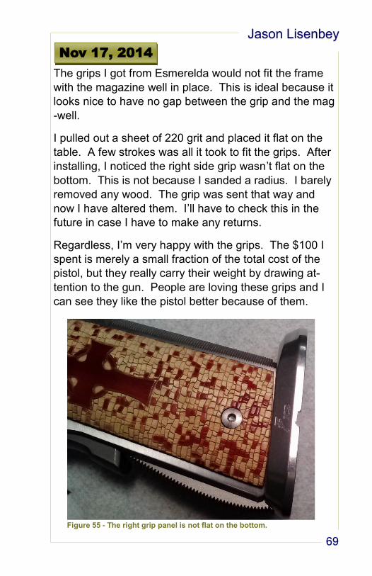
The grips I got from Esmerelda would not fit the frame
with the magazine well in place. This is ideal because it
looks nice to have no gap between the grip and the mag
-well.
I pulled out a sheet of 220 grit and placed it flat on the
table. A few strokes was all it took to fit the grips. After
installing, I noticed the right side grip wasn’t flat on the
bottom. This is not because I sanded a radius. I barely
removed any wood. The grip was sent that way and
now I have altered them. I’ll have to check this in the
future in case I have to make any returns.
Regardless, I’m very happy with the grips. The $100 I
spent is merely a small fraction of the total cost of the
pistol, but they really carry their weight by drawing at-
tention to the gun. People are loving these grips and I
can see they like the pistol better because of them.
Nov 17, 2014
Figure 55 - The right grip panel is not flat on the bottom.
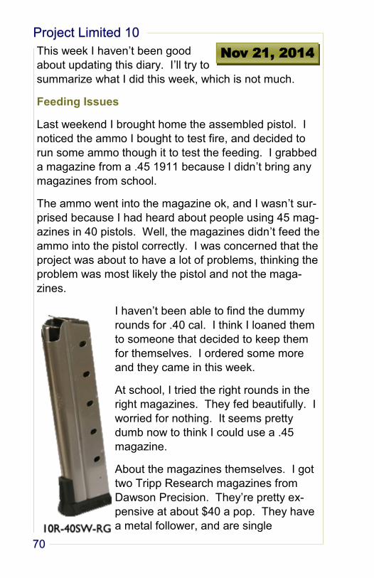
Project Limited 10
70
This week I haven’t been good
about updating this diary. I’ll try to
summarize what I did this week, which is not much.
Feeding Issues
Last weekend I brought home the assembled pistol. I
noticed the ammo I bought to test fire, and decided to
run some ammo though it to test the feeding. I grabbed
a magazine from a .45 1911 because I didn’t bring any
magazines from school.
The ammo went into the magazine ok, and I wasn’t sur-
prised because I had heard about people using 45 mag-
azines in 40 pistols. Well, the magazines didn’t feed the
ammo into the pistol correctly. I was concerned that the
project was about to have a lot of problems, thinking the
problem was most likely the pistol and not the maga-
zines.
I haven’t been able to find the dummy
rounds for .40 cal. I think I loaned them
to someone that decided to keep them
for themselves. I ordered some more
and they came in this week.
At school, I tried the right rounds in the
right magazines. They fed beautifully. I
worried for nothing. It seems pretty
dumb now to think I could use a .45
magazine.
About the magazines themselves. I got
two Tripp Research magazines from
Dawson Precision. They’re pretty ex-
pensive at about $40 a pop. They have
a metal follower, and are single
Nov 21, 2014
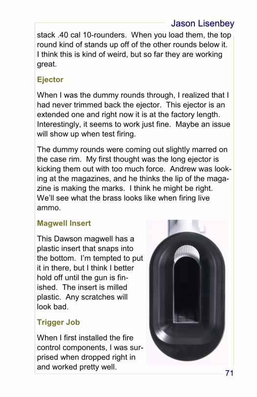
Jason Lisenbey
71
stack .40 cal 10-rounders. When you load them, the top
round kind of stands up off of the other rounds below it.
I think this is kind of weird, but so far they are working
great.
Ejector
When I was the dummy rounds through, I realized that I
had never trimmed back the ejector. This ejector is an
extended one and right now it is at the factory length.
Interestingly, it seems to work just fine. Maybe an issue
will show up when test firing.
The dummy rounds were coming out slightly marred on
the case rim. My first thought was the long ejector is
kicking them out with too much force. Andrew was look-
ing at the magazines, and he thinks the lip of the maga-
zine is making the marks. I think he might be right.
We’ll see what the brass looks like when firing live
ammo.
Magwell Insert
This Dawson magwell has a
plastic insert that snaps into
the bottom. I’m tempted to put
it in there, but I think I better
hold off until the gun is fin-
ished. The insert is milled
plastic. Any scratches will
look bad.
Trigger Job
When I first installed the fire
control components, I was sur-
prised when dropped right in
and worked pretty well.
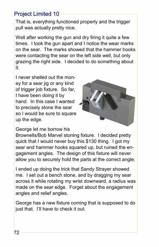
Project Limited 10
72
That is, everything functioned properly and the trigger
pull was actually pretty nice.
Well after working the gun and dry firing it quite a few
times. I took the gun apart and I notice the wear marks
on the sear. The marks showed that the hammer hooks
were contacting the sear on the left side well, but only
grazing the right side. I decided to do something about
it.
I never shelled out the mon-
ey for a sear jig or any kind
of trigger job fixture. So far,
I have been doing it by
hand. In this case I wanted
to precisely stone the sear
so I would be sure to square
up the edge.
George let me borrow his
Brownells/Bob Marvel stoning fixture. I decided pretty
quick that I would never buy this $130 thing. I got my
sear and hammer hooks squared up, but ruined the en-
gagement angles. The design of this fixture will never
allow you to securely hold the parts at the correct angle.
I ended up doing the trick that Sandy Strayer showed
me. I set out a bench stone, and by dragging my sear
across it while rotating my wrist downward, a radius was
made on the sear edge. Forget about the engagement
angles and relief angles.
George has a new fixture coming that is supposed to do
just that. I’ll have to check it out.
Jason Lisenbey
73
Disconnector
The bloody disconnector is still giving me issues. It
functions perfectly, but it just messes with the feel of the
slide operation. If you work the slide slowly, you can
feel the disconnector hit the breech face as the slide
goes forward.
I’ve worked on the breech face as much as I’m willing
to, and I’ve worked over the disconnector with the Kra-
tex wheel as much as I’m willing to. I guess this is as
good as it is going to get. I don’t know what’s wrong.
I know shortening it will help the situation, but that risks
ruining the part. The thing works just fine when the
slide is racked with authority, so I don’t know why it
bothers me so much.
Talking about it here makes me realize that I need to
play with the leaf spring some.
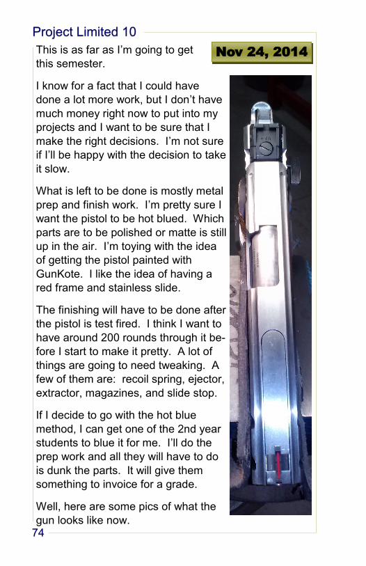
Project Limited 10
74
This is as far as I’m going to get
this semester.
I know for a fact that I could have
done a lot more work, but I don’t have
much money right now to put into my
projects and I want to be sure that I
make the right decisions. I’m not sure
if I’ll be happy with the decision to take
it slow.
What is left to be done is mostly metal
prep and finish work. I’m pretty sure I
want the pistol to be hot blued. Which
parts are to be polished or matte is still
up in the air. I’m toying with the idea
of getting the pistol painted with
GunKote. I like the idea of having a
red frame and stainless slide.
The finishing will have to be done after
the pistol is test fired. I think I want to
have around 200 rounds through it be-
fore I start to make it pretty. A lot of
things are going to need tweaking. A
few of them are: recoil spring, ejector,
extractor, magazines, and slide stop.
If I decide to go with the hot blue
method, I can get one of the 2nd year
students to blue it for me. I’ll do the
prep work and all they will have to do
is dunk the parts. It will give them
something to invoice for a grade.
Well, here are some pics of what the
gun looks like now.
Nov 24, 2014
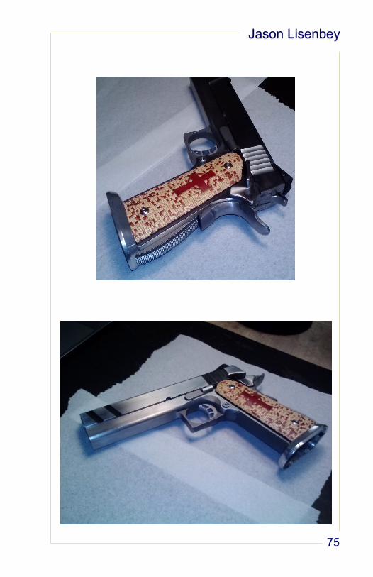
Jason Lisenbey
75