a guide to using orton pyrometric cones - auburn universitytplacek/courses/3600/guide_cones.pdf ·...
TRANSCRIPT
www.ortonceramic.com
Ceramic Foundation
P.O. Box 2760Westerville, Ohio 43086-2760
614 895-2663 • 614 895-5610 faxwww.ortonceramic.com
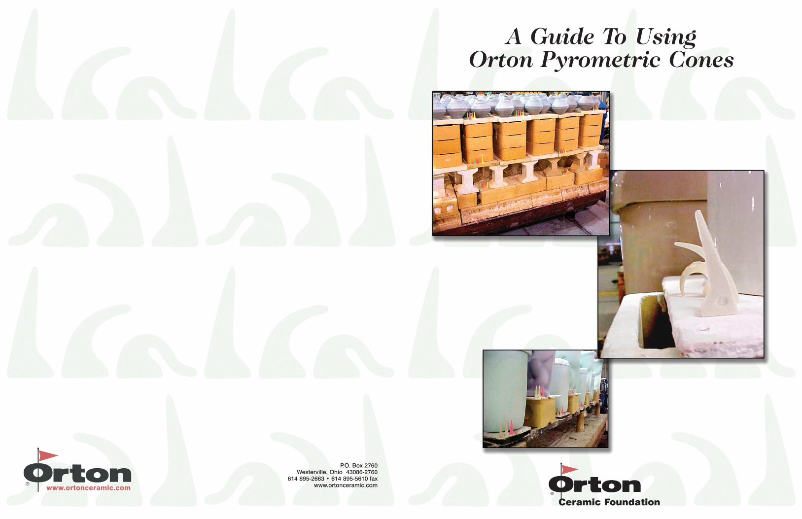
A Guide To UsingOrton Pyrometric Cones

Effect of setting angle on deformation of Large Cone 10
fired at 60˚C/hr
Setting Angle
20˚
60˚
100˚
120˚
Correct setting angle
8˚
0 4 8 12
80˚
40˚
Def
orm
atio
n
Up
Deformation quality of Large, plastic-formed #10
Standard Cones
Variation in Deformation60˚ 70˚ 80˚ 90˚ 100˚ 110˚ 120˚
X
δ=10.8 angular degrees
99%95%
68%
Product Variability
-50˚ -20˚ 0˚+10˚ +70˚
Orton Large Cones
Manufacturer A
-70˚ -60˚ -40˚ -30˚ -10˚ +20 +̊30 +̊40 +̊50 +̊60˚
Manufacturer B
Variation in deformation (angular degrees)
Comparison in deformation variability in angular degrees
-4˚ -2˚ 1285˚ +1˚ +2˚
X
Self-Supporting Cone #10
Large, plastic-formed Cone
#10
Variability in deformation of #10 Standard Cones resulting from
procedures for mounting
Variation in Deformation (Angular degrees)
Cones lab mounted
50
X
60 70 80 90 100 110 120 130
Cones mounted in commercial
plaques
determine “heatwork” and without the cumber-some task of running an array of “traveling ther-mocouples” on a special kiln car, a thermocouplecannot provide information about the uniformityof heat distribution within the kiln cross-section.
The cost-savings of using Orton PyrometricCones regularly far outweigh the cost of the conesand increases the assurance of high quality ware.
DETERMINING THE CONES TO USE
To determine the proper range of cones to beused, first determine:
• Maximum firing temperature desired • Hold or “soak” time at max temperature • Type of kiln atmosphere• Heating rate during last 200°C ramp
Using this information, establish the general fir-ing range by:
1. Using an Orton temperature equivalents chart, find the cone number for the heatingrate and maximum temperature, closest toyour actual firing conditions. (This will be your “Firing Cone”.)
2. If there is a “soak” or time hold at maxi-mum temperature, increase the “FiringCone” by one cone hotter for a one hour soak;two cones hotter for three hours of soak; and three cones hotter for nine hours of soak.
3. If the kiln has a control thermocouple locatedin the crown (Top) of the kiln, lower the “Firing Cone” by one cone since the crown is usually much hotter than the bulk of the load where the cones will be set.
4. For the test run, utilize two “Guide” (Cooler)
Cones and one “guard” (Hotter) Cone around the “Firing Cone.”
(In small kilns with a fast firing rate, approx.300°C/Hr. or more, it may be necessary to useOrton’s Small Cones which can be heated morerapidly without adverse effect.)
WHY USE ORTON’S SELF-SUPPORTING CONES?
Two critical aspects common to the proper useof all Pyrometric Cones is mounting cones atthe correct setting height and angle and doingso can cause the operator to expend muchtime and labor.
“Height Setting” impacts cone deformation dra-matically. Figure 6 and 7 show the effect of set-ting height against the angular deformation ofvarious height cones. The cones at the highestheights deformed the most and the cones mount-ed at the lowest heights deformed least.
“Angle Setting” also significantly effects conedeformation as shown in Figure 8 and Figure 9.To illustrate this, a similar procedure was used in“Height Setting”, where several cones weremounted at various angles with all other factorsremaining constant. Cones set less than thedesigned 8° angle deformed less than those setat 8° angle. The Large cones in Figure 10 are cor-rectly mounted at an 8° setting angle and atapprox. 5.08 cm (2 in.) setting height.
The need for dependence upon the human fac-tors for careful mounting has been eliminatedby Orton’s introduction of Self-SupportingCones. Orton’s revolutionary Self-SupportingCone has the correct mounting height and anglebuilt into the supporting base of the cone andallows users to have consistent, reproducibleand successful firings.
HOW DO ORTON’S SELF-SUPPORTINGCONES WORK?
Orton Foundation’s patented product design,seen in Figure 14, shows the base of the coneacts as its own base support during firing. Ortonengineers studied the problem of inconsistenciesin results caused by inaccurate mounting anddeveloped the Self-Supporting Cone. The fulcrumaround which the cone bends is precisely con-trolled through careful design and manufacturing.
Figure 15 shows a frequency distribution curvefor Self-Supporting Cones as compared to that ofOrton’s regular Large Cones, mounted in the rec-ommended manner. The variation in angulardeformation has been virtually eliminated by thepatented Self- Supporting Cone design.
ARE ORTON PYROMETRIC CONES REALLYTOP QUALITY?
The consistent performance demonstrated inFigure 16 is a better answer of our quality anddedication. It shows by photograph the typicalconsistency of 48 Orton Self-Supporting Conesfired simultaneously.
HOW DO I FIND OUT MORE ABOUT ORTONPYROMETRIC CONES?
You can visit the Orton website at www.ortonce-ramic.com and go to the section on Products forFiring where you will find a great deal of informa-tion on cones and their use or you can call us at(614) 895-2663.
figure 9
figure 10 figure 12 figure 14 figure 16
figure 15figure 11 figure 13
WHAT ARE ORTON PYROMETRIC CONES?
Developed by Edward Orton Jr. in 1896, PyrometricCones are used to measure the effects of both timeand firing temperature inside a ceramist’s kiln. Inthe ceramics industry, the combined effect of tem-perature and time is called “heatwork” and is oneof the critical aspects of successful pottery andceramics. When used correctly, Orton PyrometricCones are sensitive devices capable of indicatingdifferences in heatwork with a remarkable degreeof accuracy.
Made from over 100 carefully controlled compo-sitions containing compounds similar to the ware,pyrometric cones bend (deform) in a repeatablemanner over a temperature range of 50°F or less.The cones will soften and bend as glass formswhile attaining the desired temperature and asthe temperature and time of the firing continues.
Orton manufactures Large, Small, and Self-Supporting Cones. Large Cones are used indus-trial firms and by potters alike. The original“Standard” developed by Edward Orton Jr. in1896, Large Cones measure 21/2 in. (approx. 6.35cm) high.
Small Cones measure approx. 11/8 in. (2.86 cm)high and are composed similarly to Large Cones.Small Cones were designed to be used in kilnswith limited space. Large and Small Conesrequire some means of support to achieve thecorrect mounting angle and height.
Self-Supporting Cones also measure 21/2 in.(approx. 6.35 cm) high, and have the correctheight and angle of mounting is already built intothe cone. This makes it a simple but accurateway for the user to correctly and consistentlyreproduce firings.
WHY USE ORTON PYROMETRIC CONES?
Orton Pyrometric Cones reliably and accuratelymeasure the combined effects of both time andtemperature and can be used for the followingpurposes:
•To determine if the desired amount of “heatwork” was delivered to the product,
•Data measured by cones can be entered intoa statistical software program to provide SPC control charts,
•To measure kiln temperature uniformity, •To monitor kiln atmosphere conditions
during firing, •To provide visual evidence of fired producs’
treatment through the accumulation of cones fired in the same runs
HOW DO ORTON PYROMETRIC CONES WORK?
Pyrometric cones will “bend” or deform with theangle of the cone’s tip creating an arc that curvesdownward. The amount the tip bends can berelated to the hands of a clock and the end point temperature is reached when the conebends to a 90° angle. The tip of the cone willbend slowly at first, but as the effects of heatover an extended time take place, the cone bendsmore rapidly.
Figure 1 illustrates the combined time-tempera-ture effect of a uniform firing of a series of LargeCones number 08, 07, 06 and 05. (Orton recom-mends using a three-cone system for all your fir-ings, with a guide cone, a firing cone and a guardcone. Four cones can also be used.)
At a uniform firing in an electric kiln at 150°C/hr,Cone 08 has deformed to the point of where thetip was even with the base (955°C). At 984°C,Cone 07 deformed to the same point. After one
hour of “soaking” (exposure), Cone 06 deformedand Cone 05 deformed after three hours of soak.
Since time and temperature are important factorsin cone deformation, the rate of heating will influ-ence the cone’s deformation temperature. Figure2 is an example of three Large Cones fired simul-taneously at six different heating rates. As therate of heating increased, the temperaturerequired to reach the “End Point” temperaturealso increased. This relationship holds true formost ceramic products and glazes and a goodexample of why temperature alone is not enoughto ensure proper maturation or firing conditions.
A system of describing cone deformation basedon “clock positions” has evolved based on theobservation of the cone’s tip position in relationto an imaginary clock face. Figure 3 shows the“clock-like” deformation of Orton PyrometricCones that allows the operator to describe thecone’s actual angular deformation in relation toits original vertical position. Figure 4 is an exam-ple of a commonly employed template, marked-off in two angular degree increments for themeasurement of the cone’s deformation. In thisexample, the value of deformation of 72° “angu-lar” would be the reported result or end point.
Figure 5 illustrates the clock system of deforma-tion description or bending interval recording dur-ing the firing process. It is readily apparent thatthis bending is not linear and must be kept inmind by the operator during the firing.
IF I USE THERMOCOUPLES, WHY USE CONES?
Simple, easily handled and installed, thermocou-ples are the most commonly used temperatureindicators in industry. A thermocouple registersthe temperature “measured” at its tip, a singlepoint in space and time. A thermocouple cannot
0
200
400
600
800
1000
1 2 3 4 5 6 7 8 9 10
Time (hrs.)
Tem
pera
ture
(˚C
)
Effect of time and temperature on cone deformation
08 050607
Soak
Rate
150
˚C1 21˚
2 35˚
3 49˚
4 63˚5 77˚
6 90˚
Up 8˚
Plaque
Clock position versus angular deformation
Relation of clock positions and angular deformation for Large
Cone 10 fired at 60˚C/hr
Temperature (˚C)
Con
e P
osit
ions 20˚
60˚
100˚
120˚
10 angular degrees
represents 5˚C
8˚
1250 1260 1270 1280 1290
10 angular degrees
represents 1˚C
1
2
3
4
5
6
80˚
40˚
Clo
ck P
ositi
ons
Ang
ular
Deg
rees
Effect of setting angle on deformation of Large Cone 06
fired at 60˚C/hr
Setting Angle
20˚
60˚
100˚
120˚
Correct setting angle
8˚
0 4 8 12
80˚
40˚
Def
orm
atio
n
Up
Deformation temperature vs. rate of heating for
Large Standard Cones no. 9, 10 and 11
Rate of Heating (˚C/hr.)
Def
orm
atio
n T
emp.
(˚C
) 1,400
1,350
1,300
1,250
1,200
1,150
1,100.5 1 5 10 50 100 200 400
11109
0 10 2030
40
5060
7080
90100
110
Cone Plaque
8
Cone
Angle reported
Metal template graduated in 2˚ increments
Effect of setting height on deformation of Large
Cone 06 fired at 60˚C/hr
Setting Height (in.)
20˚
60˚
100˚
120˚
Correct setting height
8˚
17/8 2 21/8
80˚
40˚
Def
orm
atio
n
Up
Effect of setting angle on deformation of Large Cone 06
fired at 60˚C/hr
Setting Angle
20˚
60˚
100˚
120˚
Correct setting angle
8˚
0 4 8 12
80˚
40˚
Def
orm
atio
n
Up
figure 1 figure 3 figure 5 figure 7
figure 8figure 6figure 4figure 2