a guide to safe scaffolding policy for safe scaffold erection and use ... site management personnel...
TRANSCRIPT

A Guide to
Safe Scaffolding
Bobby R. DavisSeries Editor
Division of Occupational Safety and HealthN.C. Department of Labor
4 W. Edenton St.Raleigh, NC 27601-1092
Cherie K. BerryCommissioner of Labor

N.C. Department of LaborOccupational Safety and Health Program
Cherie K. BerryCommissioner of Labor
OSHA State Plan Designee
Acknowledgments
A Guide to Safe Scaffolding was initially prepared for the N.C. Department of Labor by David L. Potts. Mr.Potts has written extensively about subjects regarding construction safety and is a recognized authority in safescaffolding. This guide has been updated as of January 2001 to reflect current requirements of the standards,with an effort also made to provide helpful information as determined by the series editor.
The N.C. Department of Labor is grateful to the Scaffolding Industry Association for permission to usethe illustrations in this guide.
To obtain additional copies of this book, or if you have questions about N.C. occupational safety andhealth standards or rules, please contact:
N.C. Department of LaborBureau of Education, Training and Technical Assistance
4 W. Edenton St.Raleigh, NC 27601-1092
Phone: (919) 807-2875 or 1-800-NC-LABOR
____________________
Additional sources of information are listed on the inside back cover of this book.
____________________
The projected cost of the OSHNC program for federal fiscal year 2001–2002 is $13,222,194. Federal funding provides approximately 37 percent ofthis total.
Printed 07/02, 1M

ContentsPart Page
Foreword . . . . . . . . . . . . . . . . . . . . . . . . . . . . . . . . . . . . . . . . . . .1iiv
1 Introduction . . . . . . . . . . . . . . . . . . . . . . . . . . . . . . . . . . . . . . . .ivi1
2 Policy for Safe Scaffold Erection and Use . . . . . . . . . . . . . . . . . . ii12
3 Illustrations of Selected Types of Scaffolds . . . . . . . . . . . . . . . . . ii16
4 Types of Scaffolding and Information . . . . . . . . . . . . . . . . . . . . ii22
Glossary . . . . . . . . . . . . . . . . . . . . . . . . . . . . . . . . . . . . . ii30
References . . . . . . . . . . . . . . . . . . . . . . . . . . . . . . . . . . . . ii32
iii

ForewordScaffolding can provide an efficient and safe means to perform work. However, unsafe scaffolding proce-
dures can lead to accidents, serious injuries and death. This guide makes clear that planning ahead for theerection, use and dismantling of scaffolding can substantially reduce scaffold-related accidents and injuries.Compliance with the manufacturer’s instructions, the use of this guide and compliance with all scaffoldingstandards will help ensure a safer workplace for employees.
Safety and health in the workplace is everyone’s responsibility. Employers must be aware of workplacehazards facing their workers, and they must take appropriate action to minimize or eliminate exposure tothese hazards. Workers are responsible for following the policies, procedures and training requirementsestablished by their employers. A Guide to Safe Scaffolding discusses precautions that can prevent seriousaccidents and protect workers against fall injuries and fatalities.
N.C. Department of Labor inspectors enforce the federal Occupational Safety and Health Act through astate plan approved by the U.S. Department of Labor. The N.C. Department of Labor’s Division ofOccupational Safety and Health offers many educational programs to the public and produces publica-tions, including this guide, to help inform people about their rights and responsibilities regarding occupa-tional safety and health.
OSHA puts great emphasis on efforts to help citizens find ways to create safe and healthy workplaces.Everyone profits from working together for safety. Reading and understanding A Guide to SafeScaffolding will help you form sound occupational safety and health practices where you work.
Cherie K. BerryCommissioner of Labor
v

1Introduction
Scaffolding has a variety of applications. It is used in construction, alteration, routine maintenance andrenovation. Scaffolding offers a safer and more comfortable work arrangement compared to leaning overedges, stretching overhead and working from ladders. Suitable and sufficient scaffolding must be sup-plied for work at elevations that cannot be accomplished safely by other means. Properly erected andmaintained, scaffolding provides workers safe access to work locations, level and stable working plat-forms, and temporary storage for tools and materials for performing immediate tasks.
Accidents involving scaffolding mainly involve people falling, incorrect operating procedures, environ-mental conditions and falling materials caused by equipment failure. The causes of scaffolding accidentsinclude failures at attachment points, parts failure, inadequate fall protection, improper construction orwork rules, and changing environmental conditions (high winds, temperature extremes or the presence oftoxic gases). Additionally, overloading of scaffolding is a frequent cause of major scaffold failure.
Individuals exposed to scaffolding hazards include scaffold erectors and dismantlers, personnel work-ing on scaffolds, and employees and the general public near scaffolding. Scaffold erectors and dismantlersare at particular risk, since they work on scaffolds before ladders, guardrails, platforms and planks arecompletely installed.
This guide IS NOT INTENDED to be a guideline for compliance with all pertinent regulations enforcedunder the Occupational Safety and Health Act of North Carolina, but rather an overview of safe practicesin scaffolding procedures. Though the guide is not intended to be inconsistent with adopted standards, ifan area is considered by the reader to be inconsistent, the applicable standard should be followed.
1

2Policy for Safe Scaffold Erection and Use
Safe scaffold erection and use should begin by developing policy and work rules. Policy and work rulesshould concentrate on:
• sound design
• selecting the right scaffold for the job
• assigning personnel
• training
• fall protection
• guidelines for proper erection
• guidelines for use
• guidelines for alteration and dismantling
• inspections
• maintenance and storage
Sources of information for policy development and work rules include OSHA and ANSI standards, scaf-fold trade associations, scaffolding suppliers, and safety and engineering consultation services.
Sound DesignThe scaffold should be capable of supporting its own weight and at least four times the maximum
intended load to be applied or transmitted to the scaffold and components. Suspension ropes should becapable of supporting six times the maximum intended load. Guardrails should be able to withstand atleast 200 pounds of force on the top rail and 100 pounds on the midrail. On complex systems, the servicesof an engineer may be needed to determine the loads at particular points.
Selecting the Right Scaffold for the JobYou cannot contract away the responsibility for selecting the right scaffold for your job. But if you do
contract for scaffolding:
• Choose a scaffold supplier, rental agency and/or erector who is thoroughly knowledgeable about theequipment needed and its safe use.
• Obtain the owner’s manual prepared by the scaffolding manufacturer, which states equipment limi-tations, special warnings, intended use and maintenance requirements.
If you are to select your own scaffold, begin by reviewing the written requirements (blueprints, workorders, etc.) to determine where scaffolds should be used and the type of scaffolding needed. Make surethat the scaffolds meet all government and voluntary requirements. Consider that scaffolds are generallyrated light, medium and heavy duty. Light duty scaffolds can support a limited number of employees andhand tools. Medium duty scaffolds must be capable of safely holding workers, hand tools and the weightof construction materials being installed. Heavy duty scaffolds are needed when the scaffold must sustainworkers, tools and the weight of stored materials.
Account for any special features of the building structure in relationship to the scaffold, including dis-tinctive site conditions. Factor these considerations into your policy:
• experience of erection and working personnel
• length and kind of work tasks to be performed
2

• weight of loads to be supported
• hazards to people working on and near the scaffolding
• needed fall protection
• material hoists
• rescue equipment (particularly for suspended scaffolds)
• weather and environmental conditions
• availability of scaffolding, components, etc.
Assigning PersonnelAssign a competent person to oversee the scaffold selection, erection, use, movement, alteration, dis-
mantling, maintenance and inspection. Only assign trained and experienced personnel to work on scaf-folding. Be certain they are knowledgeable about the type of scaffolding to be used and about the properselection, care and use of fall protection equipment (perimeter protection, fall protection/work positioningbelts and full harnesses, lanyards, lifelines, rope grabs, shock absorbers, etc.).
TrainingEmployees should receive instruction on the particular types of scaffolds that they are to use.
Training should focus on proper erection, handling, use, inspection, removal and care of the scaffolds.Training must also include the installation of fall protection, particularly guardrails, and the properselection, use and care of fall arrest equipment.
The competent person(s) should receive additional training regarding the selection of scaffolds, recogni-tion of site conditions, scaffold hazard recognition, protection of exposed personnel and the public, repairand replacement options, and requirements of standards.
Site management personnel should also be familiar with correct scaffolding procedures so they can bet-ter determine needs and identify deficiencies.
Fall ProtectionGuardrails must be installed on all scaffold platforms in accordance with required standards and at
least consist of top rails, midrails and toeboards (if more than 10 feet above the ground or floor). The topedge height of toprails or equivalent member on supported scaffolds manufactured or placed in serviceafter Jan. 1, 2000, shall be installed between 38" and 45" above the platform surface. The top edge heighton supported scaffolds manufactured and placed in service before Jan. 1, 2000, and on all suspended scaf-folds where both a guardrail and a personal fall arrest system are required shall be between 36" and 45".When it is necessary to remove guardrails (for example, to off-load materials), supervision must ensurethat they are replaced quickly.
Hard hats should be worn to protect against falling objects. Mesh, screens, intermediate vertical mem-bers or solid panels should be used to safeguard employees and the public at lower levels. Ground-levelsafety can be further provided by erecting canopies; by prohibiting entry into the fall hazard area by poli-cy, barricades and signs; and by the proper placement of materials, tools and equipment on scaffolding.
Workers on suspended scaffolds must use a fall arrest system as protection against the failure of thescaffold or its components. This system will usually consist of a full body harness, lanyard, rope grab,independent vertical lifeline and an independent lifeline anchorage.
The full body harness is a belt system designed to distribute the impact energy of a fall over the shoul-ders, thighs and buttocks. A properly designed harness will permit prolonged worker suspension after afall without restricting blood flow, which may cause internal injuries. Rescue is also aided because of theupright positioning of the worker.
3

A lanyard connects the safety harness to the rope grab on the lifeline. Materials should be made of 5⁄8"nylon rope or nylon webbing. Lanyards shall be kept as short as possible to limit fall distance or riggedsuch that an employee can never free fall more than six feet.
Rope grabs contain a cam device that locks onto a lifeline when there is a hard tug or pull on the lan-yard. Care must be taken to ensure that rope grabs are properly connected to lifelines so the cam willwork correctly. Rope grabs should be placed at the highest point on the lifeline to reduce the fall distanceand unintentional disengagement.
Independent vertical lifelines (not scaffold suspension lines) of fiber rope should be used for each per-son working on the suspended scaffold. In the presence of flame or heat, wire rope lifelines should be usedwith lanyards containing shock absorbers. Vertical lifelines should extend from the anchorage point tothe ground or a safe landing place above the ground.
It is important to remember that fall protection is only as good as its anchorage. The anchorage pointsare independent points on structures where lifelines are securely attached. These points must be able tosupport at least 5,000 pounds per employee and preferably 5,400 pounds for a fall of up to six feet or3,000 pounds for a fall of two feet or less.
General Guidelines for Proper ErectionAccidents and injuries can be reduced when the guidelines in this section are followed.
Supervise the erection of scaffolding. This must be done by a person competent by skill, experience andtraining to ensure safe installation according to the manufacturer’s specifications and other requirements.
Know the voltage of energized power lines. Ensure increased awareness of location of energized powerlines; maintain safe clearance between scaffolds and power lines (i.e., minimum distance of 3' for insulat-ed lines less than 300 volts; 10' for insulated lines 300 volts or more). Identify heat sources like steampipes. Anticipate the presence of hazards before erecting scaffolds and keep a safe distance from them.
Be sure that fall protection equipment is available before beginning erection and use it as needed.Have scaffolding material delivered as close to the erection site as possible to minimize the need for man-ual handling. Arrange components in the order of erection.
Ensure the availability of material hoisting and rigging equipment to lift components to the erectionpoint and eliminate the need to climb with components. Examine all scaffold components prior to erec-tion. Return and tag “Do Not Use” or destroy defective components.
Prohibit or restrict the intermixing of manufactured scaffold components, unless: (1) the components fittogether properly, without force, (2) the use of dissimilar metals will not reduce strength, and (3) thedesign load capacities are maintained.
All scaffold decks should be planked as fully as possible (beginning at the work surface face) with gapsbetween planks no more than 1" wide (to account for plank warp and wane). (Figure 1 shows types ofplanking.) The remaining space on bearer member (between the last plank and guardrail) cannot exceed91⁄2" (the space required to install an additional plank). Guardrail systems are not required on the build-ing side when the platform is less than 16" from the building, except for suspended scaffolds where themaximum distance is 12". In addition, scaffold setbacks will depend upon the needs of the trade. As anexample, masons require the scaffold platform to be as close to the wall as possible (within 6"), while lath-ers and plasterers using spraying apparatus must stand back (and prefer a setback distance of at least18"). Platform units must not extend less than 6" over their supports unless they are cleated or containhooks or other restraining devices. When platform units are abutted together or overlapped to make along platform, each end should rest on a separate support or equivalent support. Wood preservatives, fireretardant finishes and slip-resistant finishes can be applied to platform units; however, no coating shouldobscure the top and bottom of wooden surfaces. If fire retardants are used, an engineer should ensurethat the plank(s) will carry the required load since fire retardants can reduce the plank load capacity.
Provide suitable access to and between scaffolds (see figure 4). Access can be provided by portable lad-ders; hook-on ladders; attachable ladders; stairway-type ladders; integral prefabricated scaffold rungs;
4

direct passage from another scaffold, structure or personnel hoist; ramps; runways; or similar adequatemeans. Crossbraces and scaffold frames shall not be used for access scaffold platforms unless they areequipped with a built-in ladder specifically designed for such purpose. All ladders in use must meetOSHA specifications, designed according to standards and secured against displacement. The bottomsteps of ladders must not be more than two feet from the supporting level. Rest platforms are recom-mended for at least every 30–36' of elevation. When direct access is used, spacing between scaffold andanother surface should be no more than 14" horizontally and 2 feet vertically.
Additional recommendations for the erection of supported scaffolds, suspension scaffolds, fabricatedframe scaffolds, outrigger scaffolds, etc., are also described in this booklet.
Guidelines for Use• Be certain that scaffolds and components are not loaded beyond their rated and maximum capaci-
ties.
• Prohibit the movement of scaffolds when employees are on them.
• Maintain a safe distance from energized power lines.
• Prohibit work on scaffolds until snow, ice and other materials that could cause slipping and falls areremoved.
• Protect suspension ropes from contact with sources of heat (welding, cutting, etc.) and from acidsand other corrosive substances.
• Prohibit scaffold use during storms and high winds.
• Remove debris and unnecessary materials from scaffold platforms.
• Prohibit the use of ladders and other devices to increase working heights on platforms.
Guidelines for Alteration and Dismantling• Require that scaffolds be altered, moved and dismantled under the supervision of a competent person.
• Alteration and dismantling activities should be planned and performed with the same care as witherection.
• Tag any incomplete scaffold or damaged component out of service.
InspectionsInspect all scaffolds and components upon receipt at the erection location. Return, tag “Do Not Use” or
destroy defective components. Inspect scaffolds before use and attach a tag stating the time and date ofinspection.
Inspect scaffolds before each workshift and especially after changing weather conditions and pro-longed interruptions of work. Check for such items as solid foundations, stable conditions, completeworking and rest platforms, suitable anchorage points, required guardrails, loose connections, tie-offpoints, damaged components, proper access, and the use of fall protection equipment.
Maintenance and StorageMaintain scaffolds in good repair. Only replacement components from the original manufacturer should
be used. Intermixing scaffold components from different manufacturers should be avoided. Fabricated scaf-folds should be repaired according to the manufacturer’s specifications and guidance. Job-built scaffoldsshould not be repaired without the supervision of a competent person.
Store all scaffolding parts in an organized manner in a dry and protected environment. Examine allparts and clean, repair or dispose of them as necessary.
5

3Illustrations of Selected Types of Scaffolds
Illustrations in this part offer the reader a general pictorial representation of selected types of scaffoldswhich are addressed by standards enforced under the Occupational Safety and Health Act of NorthCarolina (OSHANC standards). The reader must not rely upon the illustrations to determine safetyrequirements or safe use of the equipment for any particular installation situation. Rather, the readershould refer to the appropriate OSHANC standard and related tables for specific information. The illus-trations reference the OSHANC standards (29 CFR 1926 applies to the construction industry and 29 CFR1910 applies to general industry).
Illustrations in this part were provided by the Scaffolding Industry Association. The illustrations arenot intended by the N.C. Department of Labor or the Scaffolding Industry Association to endorse any spe-cific product, design or installation.
Figure 1
Scaffolding Work Surfaces [29 CFR 1926.451(a); 29 CFR 1910.28(a)]
6
LAMINATEDVENEERLUMBER
(LVL)SCAFFOLD PLANKS
SOLIDSAWN
LUMBER
FABRICATEDSCAFFOLD
DECK
FABRICATEDSCAFFOLD
PLANK
STAGEPLATFORM
DECORATORPLANK
WOODSCAFFOLD
PLANK
MODULARSTAGE
PLATFORM
METALSCAFFOLD
PLANK

Figure 2
Wood Pole Scaffold [29 CFR 1926.452(a); 29 CFR 1910.28(b)]
Figure 3
Tube and Coupler Scaffold [29 CFR 1926.452(b); 29 CFR 1910.28(c)]
7
POLE
PLANKED LEVELS
BEARER
GUARDRAIL SYSTEM
ACCESS LADDER
RUNNER
DIAGONAL BRACING
GUARDRAIL SYSTEMWITH TOEBOARDS
PLANKING
RIGIDCLAMP
SWIVELCLAMP
RUNNER
BEARER
POST
TYPICALJOINT
CONNECTION
CROSS-BRACING
DIAGONAL BRACE
SILL
BASE PLATE

Figure 4
Fabricated Frame Scaffold (Tubular Welded Frame Scaffold) [29 CFR 1926.452(c); 29 CFR 1910.28(d)]and Scaffold Access (Ladder or Equivalent) [29 CFR 1926.451(e); 29 CFR 1910.28(a)(12)]
8
INTERNAL STAIR UNIT
GUARDRAIL
HANDRAIL SYSTEM
CROSSBRACE
STEP UNIT
FRAME orPANEL
ACCESSGATE
INTERMEDIATELEVEL
TOEBOARDS
FRAMEor
PANEL
ACCESSLADDER
BRACKETATTACHMENT
COUPLER
EXTERNAL LADDERSBUILT-IN ATTACHABLE

Figure 5
Manually Propelled Mobile Scaffold (Fabricated Tubular Frame) [29 CFR 1926.452(w); 29 CFR 1910.29]
9
WORKPLATFORM
GUARDRAIL SYSTEMACCESS
GATE
ENDFRAME
LOCKINGPINS
CROSS-BRACING
TOEBOARD
COUPLER
ACCESSLADDER
LOCKINGCASTERS
CASTER FASTENING PINS
HORIZONTALDIAGONAL
BRACE

Figure 6
Examples of Vehicle-Mounted Elevating and Rotating Aerial Devices (covered by ANSI A92.2)[29 CFR 1926.453]
10
VEHICLE-MOUNTED AERIAL PLATFORM WITHTELESCOPING AND ROTATING BOOM
VEHICLE-MOUNTED AERIAL PLATFORM(SCISSOR TYPE)

Figure 7
Outrigger Scaffold [29 CFR 1926.452(i); 29 CFR 1910.28(e)]
11
THIS ENDRIGIDLY SECURED
OUTRIGGER BEAM BLOCKEDFOR LATERAL SUPPORT

Figure 8
Mason’s Adjustable Multiple-point Suspension Scaffold (With Winding Drum Hoists)[29 CFR 1926.452(q); 29 CFR 1910.28(f)]
12
ALTERNATE BOLT & SPECIALANCHOR IMBEDDED IN CONCRETE
AT TIME OF POUR
ANCHORAGE SYSTEM
BUILDINGSTEELTYPICAL SUPPORT FOR
STRUCTURAL STEEL
OVERHEAD PROTECTION
GUARDRAILSYSTEM
WITH SCREEN

Figure 9
(Swinging Scaffold) Two-point Suspension [29 CFR 1926.452(p); 29 CFR 1910.28(g)]
13
COUNTERWEIGHTS
TIEBACK
COUNTERWEIGHTS
TIEBACK
TIEBACKS
OUTRIGGERBEAM
ROLLINGOUTRIGGER BEAM
SECONDWIRE ROPE
WOODBLOCKING
ROOF HOOK
SUSPENSIONWIRE ROPES
PARAPET CLAMP
SUSPENSIONWIRE ROPE
SUSPENSIONWIRE ROPE
SUSPENSIONWIRE ROPES
PLATFORM
PLATFORM
MODULAR PLATFORM
POWERED TRACTION HOIST
GUARDRAIL SYSTEM WITH SCREEN & TOEBOARDS
GUARDRAIL SYSTEM WITH TOEBOARDS
POWER WINDING DRUM HOIST
GUARDRAIL SYSTEM WITHTOEBOARDS
MANUAL WINDING DRUM HOIST

Figure 10
Multiple-point Suspension Scaffold [29 CFR 1926.452(q)]
14
INDEPENDENT LINE
HOISTLINE
GUARDRAILSYSTEM
STAGE
HOIST

Figure 11
Multi-level Suspension Scaffold With Powered Hoists [29 CFR 1926.452(v)]
15
SECOND WIRE ROPE
LANYARD ATTACHED TO TROLLY LINE
GUARDRAILSYSTEM
GUARDRAILSYSTEM
SUSPENSIONWIRE ROPE
HOISTINGMACHINE
PLATFORMUNITS

Figure 12
Stone Setters’ Adjustable Multiple-point Suspension Scaffold(With Manual Winding Drum Hoists) [29 CFR 1926.452(q); 29 CFR 1910.28(h)]
Figure 13
Single-point Adjustable Suspension Scaffolds (Work Cages)[29 CFR 1926.452(o); 29 CFR 1910.28(i)]
16
HOIST LINEOUTSIDE WIRE ROPE
TOPRAIL
GUARDRAILBRACKETS
MIDRAIL
INSIDE WIREROPE
OPERATINGHANDLE
GUIDECLAMP
ROLLER BUNTER
TOEBOARD
PLATFORM CORNER BRACEBOLT
WIRE ROPEGUIDE WHEEL
PUTLOG HINGE BOLTPUTLOG
END GUARDRAILSYSTEM
TOPRAIL
MIDRAIL
INTERMEDIATEGUARDRAIL
SUPPORTGUARDRAIL
SUPPORT
TOEBOARD
END BRACKET
END GUARDRAILSYSTEM
PLATFORM SIDERAIL
POWER TRACTION HOISTWORK CAGE
POWER TRACTION HOISTWORK CAGE WITH EXTENSIONS
W
SINGLE POINT SUSPENSIONSCAFFOLD WINDING DRUM HOIST

Figure 14
Single-point Adjustable Suspension Scaffold Boatswain’s Chairs[29 CFR 1926.452(o); 29 CFR 1910.28(j)]
Figure 15
Form Scaffold Carpenter’s Bracket Scaffold (Metal)[29 CFR 1926.452(g); 29 CFR 1910.28(k)]
17
BOATSWAIN CHAIRPOWERED
BOATSWAIN CHAIRMANUAL
WALL STUD
GUARDRAILPOST
LOCATION
THRU BOLT
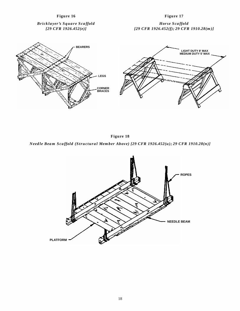
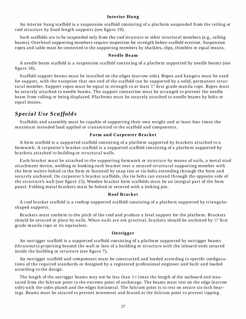
Figure 18
Needle Beam Scaffold (Structural Member Above) [29 CFR 1926.452(u); 29 CFR 1910.28(n)]
18
BEARERS
LEGS
CORNERBRACES
LIGHT DUTY 8' MAXMEDIUM DUTY 5' MAX
PLATFORM
NEEDLE BEAM
ROPES
Figure 16
Bricklayer’s Square Scaffold[29 CFR 1926.452(e)]
Figure 17
Horse Scaffold[29 CFR 1926.452(f); 29 CFR 1910.28(m)]

Figure 19
Interior Hung Scaffold [29 CFR 1926.452(t); 29 CFR 1910.28(p)]
Figure 20
Catenary Scaffold [29 CFR 1910.28(g); 29 CFR 1926.452(r)]
19
BUILDINGSTRUCTURAL MEMBER
SUPPORTING ROPE(ALTERNATE TUBE & COUPLER)
PLANK
BEARER
STRUCTURE ABOVE
PLATFORMVERTICAL PICKUPS
ANCHORED
WIRE ROPE
ANCHORED
HOOK STOPS

20
Figure 21
Ladder Jack Scaffold [29 CFR 1926.452(k); 29 CFR 1910.28(q)]
Figure 22
Window Jack Scaffold [29 CFR 1926.452(l); 29 CFR 1910.28(r)]
OVERHANG
PLANKHEAVY-DUTY
LADDER
LENGTH OF FABRICATEDPLANK VARIES
LADDER JACK(SECURE PLANK TO BOTH
LADDER JACKS)
SECURE TOP ANDBOTTOM OF BOTH
LADDERS
HEIGHT
JACK INSTALLED ON SIDEOF LADDER TOWARD
SURFACE
JACK INSTALLED ON SIDEOF LADDER AWAY FROM
SURFACE
UPPERMOST USABLERUNG—SECOND
HIGHEST
BUILDINGSTRUCTURE
ANCHOR
WINDOW OPENING

Figure 23
Float or Ship Scaffold [29 CFR 1926.452(s); 29 CFR 1910.28(u)]
Figure 24
Pump Jack Scaffold [29 CFR 1926.452(j)]
21
STRUCTURAL MEMBER
SUPPORT ROPE
EDGE PROTECTION
DECK WITH BRACING
POLE
BRACE
ENDGUARDRAIL
SYSTEM
WORK PLATFORM
PUMP JACKBRACKET
BRACE
MUD SILLS
TOEBOARD
MIDRAIL
WORKBENCH(GUARDRAIL)
POLE
STRUCTURE

22
4Types of Scaffolds and Information Regarding Their Use
There are many different types of scaffolds, each with unique features. Because of this distinctiveness,procedures for safe erection and use maybe unique to the particular scaffold. Guidelines for several scaf-folds are offered in this part. They are grouped under three categories: self-supporting scaffolds, suspen-sion scaffolds and special use scaffolds.
Self-Supporting ScaffoldsA self-supporting scaffold is one or more work platforms supported from below by outriggers, brackets,
poles, legs, uprights, posts, frames or similar supports.
General Requirements
Confirm that scaffold and assembly are capable of supporting their own weight and at least four timesthe maximum intended load applied or transmitted to the scaffold and components. Ensure that poles,legs, posts, frames and uprights bear on base plates and mud sills or other adequately firm foundations.Footings must be level, sound and able to support the loaded scaffold without settlement or displacement.Plumb or brace poles, legs, posts, frames and uprights to prevent swaying or displacement.
Any supported scaffold with a height of more than four times the minimum width of the base must berestrained from tipping by guying, tying, bracing or other suitable means. Restraints are needed for every26' (vertically), with the top restraint as close to the top platform as possible (but not further from the topthan four times the least base dimension).
Fabricated Frame
A fabricated frame scaffold (tubular welded frame scaffold) is a supported scaffold consisting of a plat-form(s) supported on fabricated end frames with integral posts, horizontal bearers and intermediatemembers (see figure 4).
Frames and panels must be supported by cross, horizontal or diagonal braces, or a mixture of braces, tostabilize vertical members. Crossbraces should be long enough to square and align vertical members, toproduce an erect scaffold that is plumb, level and square. Brace connections must be securely fastened.Frames and panels must be connected vertically by coupling, stacking pins, or equal means. Brackets sup-porting cantilevered loads must be seated with side-brackets parallel to the frames and end-brackets at 90degrees to the frames. If loads are to be placed on a platform extension, the scaffold must be restrainedfrom tipping and putlogs or knee brace extensions must be used. (Excessive loads on side brackets couldcause a frame leg failure.) Existing platforms must be left in place until new end frames have been placedand braced, prior to moving the platforms to the next level. Scaffolds over 125' high must be designed by aregistered professional engineer and be constructed and loaded consistent with the design.
Tube and Coupler
A tube and coupler scaffold is a supported scaffold consisting of platforms supported by individualpieces of tubing, erected with coupling devices connecting uprights, braces, bearers and runners (see fig-ure 3). A registered professional engineer may need to be consulted about the design, construction, andloading of the scaffold. Tube and coupler scaffolds over 125' high must be designed by a registered profes-sional engineer and be constructed and loaded consistent with the design.
Transverse bracing forming an “X” across the width of the scaffold must be installed at the scaffoldends and at least at every third set of posts horizontally (measured from only one end) and every fourthrunner vertically. Bracing must extend diagonally from the inner or outer posts or runners upward to thenext outer or inner posts or runners. Building ties must be installed at the bearer levels between thetransverse bracing and must conform to the requirements of 1926.451(c)(1). This bracing must be placedfor each section of six levels between the fourth and sixth levels. The bracing must extend diagonallyfrom the inner or outer posts or runners at the bottom of the fourth level, upward to the inner or outer

posts or runners at the bottom of the fifth level, and likewise to the sixth level. If this technique is used,the scaffold should be tied at the “k” function level.
On straight run scaffolds, longitudinal bracing across the inner and outer rows of posts must beinstalled diagonally in both directions and must extend from the base of the end posts upward to the topof the scaffold at approximately a 45 degree angle. When the length of the scaffold is greater than theheight, such bracing must be repeated starting at least with every fifth post. When the length is shorterthan the height, such bracing must be installed from the base of end posts upward to the opposite endposts and then in alternating directions until the top of the scaffold is reached.
In situations where the attachment of bracing to posts is precluded, the bracing must be attached tothe runners. Bearers must be installed transversely between the posts, and when coupled to the posts,the inboard coupler must bear directly on the runner coupler. When the bearers are coupled to the run-ners, the couplers must be as close to the posts as possible. Bearers must extend beyond the posts andrunners and provide full contact with the coupler.
The scaffold must have runners installed along its length along both the inside and outside posts at thevarious level heights. Runners must be interlocked on straight runs to create continuous lengths and becoupled to each post. Bottom runners should be located as close to the base as possible. Couplers must bemade of structural metal. When platforms are being moved to the next level, the existing platform mustbe left undisturbed until new bearers have been set in place and braced prior to receiving the new plat-forms.
Mobile
A mobile scaffold is a powered or nonpowered, portable, caster or wheel-mounted supported scaffold(see figure 5). Mobile scaffolds constructed of tube and coupler components or of fabricated frames mustconform to design, construction and loading requirements for those scaffolds. The scaffolds must bebraced by cross, horizontal or diagonal braces, or combination thereof, to prevent racking or collapse; ver-tical members must be secured together laterally so that vertical members are squared and aligned.Cross, horizontal or diagonal braces, or a combination, must be used to prevent collapse and secure verti-cal members laterally so that vertical members are squared and aligned.
Scaffolds must be plumb, level and squared. All brace connections must be secured. Platforms shouldnot extend past the base supports unless outrigger frames or equivalent devices are used to ensure stabil-ity. A rolling scaffold load capacity is also limited by the weight its casters can support. Platforms shouldnot extend past the base supports unless outrigger frames are used. A rolling scaffold load capacity is alsolimited by the weight its casters can support.
Caster and wheel stems must be pinned or otherwise secured in scaffold legs. While in a stationaryposition, casters and wheels must be locked with a positive wheel and/or wheel and swivel locks, or equiv-alent means, to prevent movement.
Employees should not be allowed to ride on a mobile scaffold unless strict controls are followed (leveland unobstructed surfaces, a height ratio to width of not more than two to one, slow speed of movement,confinement of employees within the scaffold frame, etc.) When manual force is used to move the scaffold,the force should be applied as close to the base as practicable, but not more than 5' above the supportingsurface (i.e., scaffold base or wheels when a powered system is used). Powered systems used to propelmobile scaffolds must be designed for such use. Forklifts, trucks, similar motor vehicles or add-on motorsshould not be used to propel scaffolds unless the scaffold is designed for such propulsion systems.
Pole Scaffold
A single pole scaffold is a supported scaffold consisting of platforms resting on bearers, the outsideends of which are supported on runners (ledgers or ribbons) secured to a single row of posts or uprights,and the inner ends of which are supported on or in a structure or building wall. A double pole (indepen-dent pole) scaffold is a supported scaffold consisting of platforms resting on cross beams supported byledgers and a double row of uprights independent of support (except for ties, guys and braces) from anystructure.
23

On double pole scaffolds, crossbracing must be installed between the inner and outer sets of poles (seefigure 2). Diagonal bracing in both directions must be installed across the entire outside face of double-pole scaffolds used to support loads equivalent to a uniformly distributed load of 50 pounds or more persquare foot.
On both double and single pole scaffolds, diagonal bracing must be installed across the entire outsideface. Runners and bearers shall be installed on the edges (e.g., narrow side on a 2" x 4", the edge would bethe 2" side). Bearers must extend a maximum of 3" over the outside edges of runners. Runners mustextend over a minimum of two poles and be supported by bearing blocks securely attached to the poles.
Braces, bearers and runners cannot be spliced between poles. Where wooden poles are spliced, the endsmust be squared and the upper sections must rest squarely on the lower sections. When platforms arebeing moved to the next level, the existing platforms must be left undisturbed until the new bearers havebeen set in place and braced, prior to receiving the new platforms.
Pole scaffolds over 60' in height must be designed by a registered professional engineer and must beconstructed and loaded in accordance with that design.
Bricklayer’s Square
A bricklayer’s square scaffold is a supported scaffold composed of framed squares that support a plat-form (see figure 16). These types scaffolds must not exceed three tiers in height and be so constructed andarranged that one square rests directly above the other.
Scaffolds made of wood must be reinforced with gussets on both sides of each corner. Diagonal bracesmust also be installed between squares on the rear and front sides of the scaffold and must extend fromthe bottom of each square to the top of the next square. The upper tiers of the scaffold must stand on acontinuous row of planks laid across the next lower tier and nailed down or otherwise secured to preventdisplacement.
Suspension ScaffoldsA suspension scaffold is one or more platforms suspended by ropes or other non-rigid means from an
overhead structure(s).
General Requirements
Each scaffold and scaffold component must be capable of supporting, without failure, its own weightand at least four times the maximum intended load applied or transmitted to it. Each suspension rope,including connecting hardware, used on non-adjustable suspension scaffold must be capable of support-ing, without failure, at least six times the maximum intended load applied or transmitted to that rope.The stall load of any scaffold must not exceed three times its rated load.
Criteria for suspension scaffolds. All suspension scaffold support devices must rest on surfacescapable of supporting at least four times the load imposed on them by the scaffold operating at the ratedload of the hoist (or at least 1.5 times the load imposed on them by the scaffold at the stall capacity of thehoist, whichever is greater). The scaffold support devices are those such as outrigger beams, cornicehooks, parapet clamps and similar devices. Suspension scaffold outrigger beams, when used, must bemade of structural metal or equivalent strength material and must be restrained to prevent movement.
The inboard ends of suspension scaffold outrigger beams must be stabilized by bolts or other direct con-nections to the floor or roof deck, or they must have their inboard ends stabilized by counterweights.However, masons’ multi-point adjustable suspension scaffold outrigger beams must not be stabilized bycounterweights. Tiebacks must be used to secure outrigger beams that are not stabilized by bolts or otherdirect connections to the floor or roof deck. Tiebacks must be equivalent in strength to the suspension ropes.
Before the scaffold is used, a competent person must evaluate direct connections to confirm that thesupporting surfaces are capable of supporting the loads to be imposed. In addition, as related to masonsmulti-point adjustable suspension scaffold, connections must be designed by an engineer experienced insuch scaffold design.
24

Counterweights must be secured by mechanical means to the outrigger beams to prevent accidentaldisplacement; counterweights must not be removed from an outrigger beam until the scaffold is disas-sembled.
Support devices such as cornice hooks, roof hooks, roof irons, parapet clamps or similar devices must bemade of steel, wrought iron or materials of equivalent strength. They must be supported by bearingblocks and secured against movement by tiebacks installed at right angles to the face of the building orstructure. Sound points of anchorage include structural members, but do not include standpipes, vents,other piping systems or electrical conduit. Tiebacks must be equivalent in strength to the hoisting rope.
Suspension scaffold power-operated hoists and manual hoists must be tested and listed by a qualifiedtesting laboratory. Gasoline powered equipment and hoists must not be used on suspension scaffolds.Gears and brakes of power-operated hoist used on suspension scaffolds must be enclosed.
In addition to the normal operating brake, suspension scaffold power-operated hoists and manuallyoperated hoists must have a braking device or locking pawl that engages when the hoist exceeds normaldescent speed (makes either an instantaneous change in momentum or an accelerated over-speed).Manually operated hoists require a positive crank force to descend. At least four wraps of suspension ropemust be maintained at the lowest point of scaffold travel when winding drum hoists are used. When othertypes of hoists are used, the suspension ropes must be of sufficient length to allow the scaffold to be low-ered without the rope end passing through the hoist, or the rope end must be designed to prevent the endfrom passing through the hoist.
Suspension ropes supporting adjustable suspension scaffolds must be of a diameter large enough toprovide sufficient surface area for proper functioning of brake and hoist mechanisms. Wire suspensionrope may only be joined together by eye splice thimbles connected with shackles or coverplates and bolts.Load ends of wire suspension ropes must be equipped with proper size thimbles and secured by eye-splic-ing or equivalent means. Swaged attachments or spliced eyes on wire suspension rope must be made by awire rope manufacturer or qualified person. Wire rope clips must be retightened after initial loading andinspected and retightened regularly. Repair of a defective or damaged wire rope is prohibited.
Single-point Adjustable (Boatswain’s Chairs)
A single-point adjustable suspension scaffold is a suspension scaffold consisting of a platform suspend-ed by one rope from an overhead support and equipped with means to permit the movement of the plat-form to desired work levels (see figure 14).
The supporting rope for the scaffold must remain vertical from the scaffold and suspension device.Tackle for a boatswain’s chair must have the correct size ballbearing or bushed blocks and properly eye-spliced first grade manila rope of at least 5⁄8". Seat slings must be reeved through four corner holes in theseat, crossed on the underside of the seat and rigged to prevent slippage. Seat slings must be of at least5⁄8" fiber or synthetic rope or its equivalent, except when employees are using a heat producing process(e.g., gas or arc welding), then wire rope of at least 3⁄8" must be used. Boatswain’s chairs that are not cross-laminated wood must be reinforced on the underside by cleats to prevent splitting.
When two single-point suspension scaffolds are joined to create a two-point suspension scaffold, thescaffold must meet the requirements of a two-point scaffold. Powered single-point adjustable scaffoldswill require the use of a minimum 5⁄16" diameter wire rope and hoists rated by a nationally recognized lab-oratory.
Two-point Adjustable (Swing Stage)
A two-point suspension scaffold (swing stage) is a suspension scaffold consisting of a platform support-ed by hangers (stirrups) suspended by two ropes from overhead supports and equipped with means topermit the raising and lowering of the platform to desired work levels (see figure 9).
Platforms may not be more than three feet wide unless designed by a qualified person to preventunstable conditions. Platforms can be ladder-type, plank-type, beam-type, light metal-type or modular-truss type. The light metal-type should be tested and listed by a nationally recognized laboratory.
25

Platforms must be secured to hangers (stirrups) by U-bolts or equivalent means. The blocks for fiberand synthetic ropes must consist of a minimum of one double and one single block. The sheaves must fitthe size of rope. The scaffolds must be tied or secured by other means to prevent swaying.
Scaffolds specially designed as two-point scaffolds may not be connected together during raising andlowering operations. Two-point scaffolds designed for use in multiple-point scaffolds can be bridgedtogether if the connections are articulated and the hoist is seized properly. Passage between one platformto another is permissible only when the platforms are at the same height, closely abutted, and walk-through stirrups specially designed for this purpose are used.
Multiple-point Adjustable
A multiple-point adjustable suspension scaffold is a suspension scaffold consisting of a platform(s) sus-pended by more than two ropes from overhead supports and equipped with means to permit the raisingand lowering of the platform to desired work levels (see figure 10).
A stone setter’s multiple-point adjustable suspension scaffold is a two-point or multiple-point adjustablesuspension scaffold designed and used for stone setting operations. A mason’s adjustable suspension scaffoldis a two-point or multiple-point adjustable suspension scaffold designed and used for masonry operations.
Two or more scaffolds may not be bridged together unless specially designed to be bridged, the bridgeconnections are articulated, and the hoists are seized properly. If bridges are not used, passage may bemade from one platform if the platforms are at the same height and closely abutted. Scaffolds must besuspended from metal outriggers, iron brackets, wire rope slings, iron hooks or equal means. Scaffold con-nections for mason’s adjustable suspension scaffolds must be designed by an engineer experienced in scaf-fold design.
Multi-level
A multi-level suspended scaffold is a two-point or multiple-point adjustable suspension scaffold with aseries of platforms at various levels supported by common stirrups (see figure 11). Such scaffolds must haveadded independent support lines equal to the number of points supported and equal in strength to the sus-pension lines. Independent support lines and suspension ropes may not be attached to the same anchoragepoints. Platform supports must be attached to the support stirrup and not to any other platform.
Catenary
A catenary scaffold is a suspension scaffold consisting of a platform fastened to two essentially hori-zontal and parallel ropes, which are secured to structural members. Horizontal ropes are usually sup-ported by intermediate vertical pickup ropes to reduce sag and anchorage load (see figure 20). Only oneplatform may be placed between consecutive vertical pickups and no more than two platforms maybeused.
Wire rope supported platforms must have hook-shaped stops on each end. Hooks must be situated toprevent the platform from falling in the event that one wire rope breaks. Supporting ropes should beequal to 1⁄2" improved plow steel wire rope. Care must be taken to prevent overtightening of wire ropes,which can cause excessive force at anchorages and overstressing by the scaffold load. Wire ropes must becontinuous without splices between anchors.
Float (Ship)
A float (ship) scaffold is a suspension scaffold consisting of a braced platform resting upon two parallelbearers and hung from overhead supports by ropes of fixed length (see figure 23).
The platform must be supported by at least two bearers, each projecting a minimum of six inchesbeyond the platform. Support ropes must be equal in strength to at least 1" first grade manila rope.Rope connections must be made to ensure that the platform will not shift or slip. If only two ropes areused for each float, they must be arranged to supply four ends, which are securely attached to overheadsupports. Each supporting rope must be hitched around one end of the bearer and pass under the plat-form to the other end of the bearer where it is hitched again, leaving sufficient rope at each end for thesupporting ties.
26
Interior Hung
An interior hung scaffold is a suspension scaffold consisting of a platform suspended from the ceiling orroof structure by fixed length supports (see figure 19).
Such scaffolds are to be suspended only from the roof structure or other structural members (e.g., ceilingbeams). Overhead supporting members require inspection for strength before scaffold erection. Suspensionropes and cable must be connected to the supporting members by shackles, clips, thimbles or equal means.
Needle Beam
A needle beam scaffold is a suspension scaffold consisting of a platform supported by needle beams (seefigure 18).
Scaffold support beams must be installed on the edges (narrow side). Ropes and hangers must be usedfor support, with the exception that one end of the scaffold can be supported by a solid, permanent struc-tural member. Support ropes must be equal in strength to at least 1" first grade manila rope. Ropes mustbe securely attached to needle beams. The support connection must be arranged to prevent the needlebeam from rolling or being displaced. Platforms must be securely attached to needle beams by bolts orequal means.
Special Use ScaffoldsScaffolds and assembly must be capable of supporting their own weight and at least four times the
maximum intended load applied or transmitted to the scaffold and components.
Form and Carpenter Bracket
A form scaffold is a supported scaffold consisting of a platform supported by brackets attached to aformwork. A carpenter’s bracket scaffold is a supported scaffold consisting of a platform supported bybrackets attached to building or structural walls.
Each bracket must be attached to the supporting formwork or structure by means of nails, a metal studattachment device, welding or hooking each bracket over a secured structural supporting member withthe form walers bolted to the form or fastened by snap ties or tie bolts extending through the form andsecurely anchored. On carpenter’s bracket scaffolds, the tie bolts can extend through the opposite side ofthe structure’s wall (see figure 15). Wooden bracket form scaffolds must be an integral part of the formpanel. Folding metal brackets must be bolted or secured with a locking pin.
Roof Bracket
A roof bracket scaffold is a rooftop supported scaffold consisting of a platform supported by triangularshaped supports.
Brackets must conform to the pitch of the roof and produce a level support for the platform. Bracketsshould be secured in place by nails. When nails are not practical, brackets should be anchored by 3⁄4" firstgrade manila rope or its equivalent.
Outrigger
An outrigger scaffold is a supported scaffold consisting of a platform supported by outrigger beams(thrustouts) projecting beyond the wall or face of a building or structure with the inboard ends securedinside the building or structure (see figure 7).
An outrigger scaffold and components must be constructed and loaded according to specific configura-tions of the required standards or designed by a registered professional engineer and built and loadedaccording to the design.
The length of the outrigger beams may not be less than 11⁄2 times the length of the outboard end mea-sured from the fulcrum point to the extreme point of anchorage. The beams must rest on the edge (narrowside) with the sides plumb and the edges horizontal. The fulcrum point is to rest on secure six-inch bear-ings. Beams must be secured to prevent movement and braced at the fulcrum point to prevent tipping.
27

Inboard ends must be securely anchored by braced struts bearing against sills contacting overheadbeams or the ceiling, or tension members secured to the floor joists underfoot, or both, as necessary. Thesupporting structure must be braced to eliminate any horizontal movement. Platform units must benailed, bolted or otherwise firmly affixed to outriggers. The front end of the platform must be positionedno more than three inches from the structure.
Pump Jack
A pump jack scaffold is a supported scaffold consisting of a platform supported by vertical poles andmovable support brackets (see figure 24).
Brackets, braces and accessories for pump jack scaffolds must be fabricated from metal plates andangles. Two positive gripping devices are required for each bracket. Poles must be secured to structuresby rigid triangular bracing or its equivalent at the bottom, top, and other points.
When it is necessary to raise the platform, crossbracing must be added about four feet on the side oppo-site the pump jack brace and be left in place until the pump jack has been moved and the initial bracehas been reinstalled. If wood poles are used, the lumber must be straight-grained, free of shakes andlarge loose or dead knots and other imperfections that may reduce the strength of the wood. If two consec-utive lengths are used to form the wood poles, the poles are to be connected together with the seam paral-lel to the bracket. If 2" x 4" lumber is used to create a pole, the splices must be strong enough to maintainthe full strength of the member. Workbenches may not be used as scaffold platforms.
Ladder Jack
A ladder jack scaffold is a supported scaffold consisting of a platform supported by brackets attached toladders (see figure 21).
The maximum allowable height for a ladder jack scaffold is 20 feet. Only manufactured ladders may beused. Ladders must meet required standards. Ladders supporting ladder jacks must be situated, fastenedor contain devices to prevent slipping. The ladder jack must be designed and used so that it bears only onthe side rails or only on the ladder rungs. If on the rungs, the contact on each rung must be a minimum of10 inches. Platforms must be at least 12 inches wide and may not be bridged one to another.
Window Jack
A window jack scaffold is a supported scaffold consisting of a platform supported by a bracket or jackthat projects through a window opening (see figure 22).
Window jack scaffolds must be securely attached to window openings. Use should be restricted to thework only at the window opening. Jacks may not be used to support other types of scaffolding and planksor platforms placed between one window jack and another window jack.
Horse
A horse scaffold means a supported scaffold consisting of a platform supported by construction horses(see figure 17).
Horse scaffolds must be built to a height of no more 10 feet or two tiers, whichever is less. When tiersare used, each horse must be placed immediately over the horse of the lower tier. The legs of each horsemust be nailed to prevent dislocation. Each tier must be crossbraced.
Crawling Boards
A crawling board (chicken ladder) is a supported scaffold consisting of a plank with cleats spaced andsecured to provide footing for use on sloped surfaces such as roofs.
During roof construction or repair or maintenance, crawling boards must extend from the roof peak tothe eaves. Crawling boards must be secured to the roof by ridge hooks or equal means.
Step, Platform and Trestle Ladder
A step, platform and trestle ladder scaffold is a supported scaffold consisting of a platform supporteddirectly on the rungs of step ladders or a building wall.
28

Platforms may not be placed higher than the second highest rung or step of the supporting ladder.Ladders must be located, secured or contain devices to avert slipping. Scaffolds may not be bridged one toanother.
Aerial Lifts
General requirements: Aerial lifts include the following types of vehicle-mounted aerial devices usedto elevate personnel to job-sites above ground: extensible boom platforms, aerial ladders, articulatingboom platforms, vertical towers and a combination of any of this equipment. Aerial equipment may bemade of metal, wood, fiberglass reinforced plastic (FRP) or other material. It may be powered or manuallyoperated. Such equipment and/or devices are deemed to be aerial lifts whether or not they are capable ofrotating about a substantially vertical axis. Aerial lifts acquired for use on or after Jan. 22, 1973, must bedesigned and constructed in conformance with the applicable requirements of American NationalStandards for “Vehicle Mounted Elevating and Rotating Work Platforms,” ANSI A92.2-1969, includingappendix.
Aerial lifts may be “field modified” for uses other than those intended by the manufacturer providedthe modification has been certified in writing by the manufacturer or by any other equivalent entity (suchas a nationally recognized testing laboratory). The modification(s) to aerial lifts should be done in mannerto be in conformity with all applicable provisions of ANSI A92.2-1969 and appropriate section of OSHAstandards (i.e., 1926.453) to be at least as safe as the equipment was before modification.
Specific requirements:
Ladder trucks and tower trucks. Aerial ladders must be secured in the lower traveling position bythe locking device on top of the truck cab/and the manually operated device at the base of the ladderbefore the truck is removed for the highway travel.
Extensible and articulating boom platforms. Lift controls must be tested each day prior to use todetermine that such controls are in safe working condition. Only authorized individuals can operate anaerial lift. Belting off to an adjacent pole, structure or equipment while working from an aerial lift is notpermitted. Employees are required to always stand firmly on the floor of the basket. The employee mustnot sit or climb on the edge of the basket or use planks, ladders or other devices for a work position. Abody belt must be worn and a lanyard attached to the boom or basket when working from an aerial lift.(Note: Body belt(s) can serve as a positioning device; body belts are not acceptable as part of a personalfall arrest system.)
Boom and basket load limits specified by the manufacturer must not be exceeded. The brakes must beset and when outriggers are used, they must be positioned on pads or a solid surface. Wheel chocks mustbe installed before using an aerial lift on an incline, provided they can be safely installed. An aerial lifttruck must not be moved when the boom is elevated in a working position with men in the basket, exceptfor equipment that is specifically designed for this type of operation.
Articulating boom and extensible boom platforms, primarily designed as personnel carriers, must haveboth platform (upper) and lower controls. Upper controls must be in or beside the platform within easyreach of the operator. Lower controls must provide for overriding the upper controls. Controls must beplainly marked as to their function. Lower level controls must not be operated unless permission hasbeen obtained from the employee in the lift, except in case of emergency. Climbers cannot be worn whileperforming work from an aerial lift. The insulated portion of an aerial lift must not be altered in anymanner that might reduce its insulating value. Before moving an aerial lift for travel, the boom(s) mustbe inspected to see that it is properly cradled and outriggers are in stowed position (except as permittedotherwise by this section of the safety standard).
29

GlossaryAerial Device. Any vehicle mounted, telescoping or articulating, or both, used to position personnel
(workers).
Aerial Ladder. An aerial device consisting of a single- or multiple-section extensible ladder.
Articulating Boom Platform. An aerial device with two or more hinged boom sections.
Bearer. A horizontal transverse scaffold member (which may be supported by ledgers or runners) uponwhich the scaffold platform rests and joins scaffold uprights, posts, poles and similar members.
Brace. A tie that holds one scaffold member in a fixed position with respect to another member. Bracealso means a rigid type of connection holding a scaffold to a building or structure.
Cleat. A structural member used at the ends of platform units to prevent the units from slipping offtheir supports. Cleats are also used to provide footing on sloped surfaces such as crawling boards.
Coupler. A device for locking together the component tubes of a tube and coupler scaffold.
Equivalent. An alternative design, material or method that the employer can demonstrate will provide anequal or greater degree of safety for employees than the method or item specified in the standard.
Extensible Boom Platform. An aerial device (except ladders) with a telescopic or extensible boom.Telescopic derricks with personnel platform attachments are considered to be extensible boom platformswhen used with a personnel platform.
Harness. A design of straps that is secured about the employee in a manner to distribute the arrestingforces over at least the thighs, shoulders and pelvis, with provisions for attaching a lanyard, lifeline ordeceleration device.
Hoist. A mechanical device to raise or lower a suspended scaffold. It can be mechanically powered ormanually operated.
Insulated Aerial Device. An aerial device designed for work on energized lines and apparatus.
Ladder Stand. A mobile, fixed-size, self-supporting ladder that appears as a wide flat tread ladder inthe form of stairs.
Ledger. A horizontal scaffold member upon which bearers rest. It is the longitudinal member that joinsscaffold uprights, posts, poles and similar members.
Maximum Intended Load. The total load of all employees, equipment, tools, materials, transmittedloads, wind loads, and other loads reasonably anticipated to be applied to a scaffold or scaffold componentat any one time.
Mechanically Powered Hoist. A hoist that is powered by other than human energy.
Outrigger. The structural member of a supported scaffold used to increase the base width of a scaffoldin order to provide greater stability for the scaffold.
Outrigger Beam. The structural member of a suspension scaffold or outrigger scaffold that providessupport for the scaffold by extending the scaffold point of attachment to a point out and away from thestructure or building.
Personal Fall Arrest System. A system used to arrest an employee in a fall from a working level. It con-sists of an anchorage, connectors, a body belt or body harness and may include a lanyard, decelerationdevice, lifeline or suitable combinations of these. The use of a body belt for fall arrest is prohibited.
Platform. The horizontal working surface of a scaffold.
Platform. Any personnel-carrying device (basket or bucket) that is a component of an aerial device.
Platform Unit. The individual wood planks, fabricated planks, fabricated decks and fabricated platformsthat compose the platforms and walkways of a scaffold.
30

Positioning Device System. A body belt or body harness system rigged to allow an employee to be sup-ported on an elevated vertical surface, such as a wall, and work with both hands free while leaning.
Runner. The lengthwise horizontal bracing or bearing member that supports bearers on tube and cou-pler scaffolds.
Scaffold. Any temporary elevated or suspended platform and its supporting structure used for supportingemployees or materials or both, except this term does not include crane or derrick suspended personnel plat-forms.
Scissor Lift. A self-propelled or manually propelled lifting personnel platform (within wheel base) capa-ble of vertical movement with onboard controls as defined by ANSI/SIA A92.6-1990.
Vertical Pickup. A rope used to support the horizontal rope in catenary scaffolds.
Walkway. A portion of a scaffold platform used only for access and is not a work level.
Work Level. An elevated platform used for supporting employees and their materials where work activi-ties are performed.
31

ReferencesCloe, William W. May 1979. Occupational Fatalities Related to Scaffolds as Found in Reports of OSHA
Fatality/Catastrophe Investigations. U.S. Department of Labor, Occupational Safety and HealthAdministration.
Construction Safety Association of Ontario. September/October 1990. “Suspended Access.”Construction Safety. Construction Safety Association of Ontario.
Ellis, Nigel J. January 1983. “Suspended Scaffolding: Proper Protection Reduces Fall Injuries.”Occupational Health & Safety.
“Fall Protection.” July 1990. Construction Safety. Construction Safety Association of Ontario.
Hinson, J. R. October 1988. “Careful Selection, Use of Scaffolds Imperative to Accident Prevention.”Occupational Health and Safety.
International Labor Organization. 1983. “Scaffolding.” Encyclopedia of Occupational Health & Safety,vol. II, L–Z, International Labor Organization.
Kliwinski, D. P. October 1988. “Elevated Workplaces: Ladders and Scaffolds.” Center for Excellence inConstruction Safety Newsletter. West Virginia University, Center for Excellence in Excavation.Morgantown, WV.
National Safety Council. 1980. Accident Prevention Manual for Industrial Operations. 8th ed. Editedby F. E. McElroy. Chicago: NSC.
N.C. Department of Labor. 1999. North Carolina Occupational Safety and Health Standards forGeneral Industry. Subpart D—Walking-Working Surfaces; Subpart F—Powered Platforms, Manlifts, andVehicle-Mounted Work Platforms. N.C. Department of Labor, Division of Occupational Safety and Health.Raleigh.
N.C. Department of Labor. 1994. North Carolina Occupational Safety and Health Standards for theConstruction Industry. Subpart L—Scaffolding. N.C. Department of Labor, Division of OccupationalSafety and Health. Raleigh.
Potts, D. L. 1985. “An Assessment of Carpenter’s Injury Risks Needing Research.” NIOSH Report:DSR-85-0458 O.M. National Constructors Association.
Potts, D. L. Spring 1991. “Fall Prevention and Protection.” Excel, vol. 4, no. 3. West Virginia University,Center for Excellence in Construction Safety. Morgantown, WV.
U.S. Department of Labor, OSHA 3150, 2000 (Reprinted); A Guide to Scaffold Use in the ConstructionIndustry.
U.S. Department of Labor. May 1983. “Survey of Scaffold Accidents Resulting in Injuries, 1978.” U.S.Department of Labor, Bureau of Labor Statistics.
32

The following industry guides are available from the N.C. Department of Labor’s Division of
Occupational Safety and Health:
1#1. A Guide to Safety in Confined Spaces
1#2. A Guide to Procedures of the Safety and Health Review Board of North Carolina
1#3. A Guide to Machine Safeguarding
1#4. A Guide to OSHA in North Carolina
1#5. A Guide for Persons Employed in Cotton Dust Environments
1#6. A Guide to Lead Exposure in the Construction Industry
1#7. A Guide to Bloodborne Pathogens in the Workplace
1#8. A Guide to Voluntary Training and Training Requirements in OSHA Standards
1#9. A Guide to Ergonomics
#10. A Guide to Farm Safety and Health
#11. A Guide to Radio Frequency Hazards With Electric Detonators
#12. A Guide to Forklift Operator Training
#13. A Guide to the Safe Storage of Explosive Materials
#14. A Guide to the OSHA Excavations Standard
#15. A Guide to Developing and Maintaining an Effective Hearing Conservation Program
#17. A Guide to Asbestos for Industry
#18. A Guide to Electrical Safety
#19. A Guide to Occupational Exposure to Wood and Wood Dust
#20. A Guide to Crane Safety
#21. A Guide to School Safety and Health
#23. A Guide to Working With Electricity
#25. A Guide to Personal Protective Equipment
#26. A Guide to Manual Materials Handling and Back Safety
#27. A Guide to the Control of Hazardous Energy (Lockout/Tagout)
#28. A Guide to Eye Wash and Safety Shower Facilities
#29. A Guide to Safety and Health in Feed and Grain Mills
#30. A Guide to Working With Corrosive Substances
#31. A Guide to Formaldehyde
#32. A Guide to Fall Prevention in Industry
#33. A Guide to Office Safety and Health
#34. A Guide to Safety and Health in the Poultry Industry
#35. A Guide to Preventing Heat Stress
#36. A Guide to the Safe Use of Escalators and Elevators
#37. A Guide to Boilers and Pressure Vessels
#38. A Guide to Safe Scaffolding
#39. A Guide to Safety in the Textile Industry
#40. A Guide to Emergency Action Planning
#41. A Guide to OSHA for Small Businesses in North Carolina

Occupational Safety and Health (OSHNC)Sources of Information
You may call 1-800-NC-LABOR to reach any division of the N.C. Department of Labor; or visit theNCDOL home page on the World Wide Web, Internet Web site address: http://www.nclabor.com.N.C. Division of Occupational Safety and Health
Mailing Address: Physical Location:4 W. Edenton St. 111 Hillsborough St.Raleigh, NC 27601-1092 (Old Revenue Building, 3rd Floor)Local Telephone: (919) 807-2900 Fax: (919) 807-2856
For information concerning education, training and interpretations of occupational safety and health standardscontact:Bureau of Education, Training and Technical Assistance
Mailing Address: Physical Location:4 W. Edenton St. 111 Hillsborough St.Raleigh, NC 27601-1092 (Old Revenue Building, 4th Floor)Telephone: (919) 807-2875 Fax: (919) 807-2876
For information concerning occupational safety and health consultative services and safety awards programscontact:Bureau of Consultative Services
Mailing Address: Physical Location:4 W. Edenton St. 111 Hillsborough St.Raleigh, NC 27601-1092 (Old Revenue Building, 3rd Floor)Telephone: (919) 807-2899 Fax: (919) 807-2902
For information concerning migrant housing inspections and other related activities contact:Agricultural Safety and Health Bureau
Mailing Address: Physical Location:4 W. Edenton St. 111 Hillsborough St.Raleigh, NC 27601-1092 (Old Revenue Building, 2nd Floor)Telephone: (919) 807-2923 Fax: (919) 807-2924
For information concerning occupational safety and health compliance contact:Safety and Health Compliance District Offices
Raleigh District OfficeTelephone: Safety (919) 662-4597 Fax: (919) 662-4709
Health (919) 662-4711Charlotte District Office (901 Blairhill Road, Suite 200, Charlotte, NC 28217-1578)Telephone: Safety (704) 342-6163 Fax: (704) 342-5919Winston-Salem District Office (901 Peters Creek Parkway, Winston-Salem, NC 27103-4551)Telephone: Safety (336) 761-2700 Fax: (336) 761-2326
Health (336) 761-2700 Fax: (336) 761-2130Wilmington District Office (1200 N. 23rd St., Suite 205, Wilmington, NC 28405-1824)Telephone: (910) 251-2678 Fax: (910) 251-2654
***To make an OSHA Complaint, OSHNC Complaint Desk: (919) 807-2796***For statistical information concerning program activities contact:Planning, Statistics and Information Management
Mailing Address: Physical Location:4 W. Edenton St. 111 Hillsborough St.Raleigh, NC 27601-1092 (Old Revenue Building, 2nd Floor)Telephone: (919) 807-2950 Fax: (919) 807-2951
For information about books, periodicals, vertical files, videos, films, audio/slide sets and computer databasescontact:N.C. Department of Labor Library
Mailing Address: Physical Location:4 W. Edenton St. 111 Hillsborough St.Raleigh, NC 27601-1092 (Old Revenue Building, 5th Floor)Telephone: (919) 807-2848 Fax: (919) 807-2849
N.C. Department of Labor (Other than OSHNC)4 W. Edenton St.Raleigh, NC 27601-1092Telephone: (919) 733-7166 Fax: (919) 733-6197