a guide to ground source heating - forkers guide to ground source...loops installed in drilled...
TRANSCRIPT
Civil & Ground Engineering Contractors
Golds Green House, Shaw Street, West Bromwich, West Midlands. B70 0TX. Tel 0121 505 1010. Fax 0121 505 1026
Forkers Scotland Ltd - Central Dock Road, Grangemouth, FK3 8UB.Tel: 01506 466500. Fax: 01506 466501
E-mail [email protected] Web site www.forkers.com
1.0 An Introduction to Ground Source
From about 2m below ground level, the naturally
occurring temperature of rocks, soils and groundwater
in the earths crust stays at a fairly stable, albeit low
level.
The heat energy stored at shallow depths in the earths
crust is in fact stored solar energy and is therefore
continuously renewed from the sun’s solar radiation
and is therefore true renewable energy.
This ‘Ground Source’ heat energy can be exploited to
heat (or cool) buildings using a ground source heat
pump (GSHP).
If designed correctly GSHP systems can provide a
sustainable energy source at a lower cost than
traditional energy sources.
Ground source heat should not be confused with true
Geothermal Energy which comes from hot water and
rocks much deeper in the earths crust.
1.1 The Earth as a Heat Source
Solar radiation is absorbed by the earths surface with
seasonal variations affecting the upper 15m or so, the
variation is most pronounced in the top two metres.
Deeper rocks and soils stay fairly uniform in
temperature throughout the year, roughly equating to
the average air temperature of the location.
50°C
35°C
12 °C
0°C
A Guide to Ground Source Heating
Ground Source heating and cooling is one of the easiest forms of renewable energy to install in buildings and in
doing so enables a substantial reduction in greenhouse gas emissions. It is suitable for any residential,
commercial, retail and public building.
Ground Source Heating
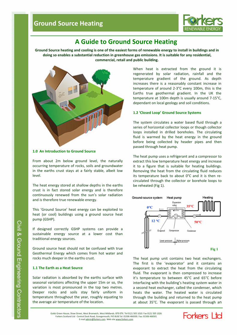
When heat is extracted from the ground it is
regenerated by solar radiation, rainfall and the
temperature gradient of the ground. As depth
increases there is a reasonably constant increase in
temperature of around 2-3°C every 100m, this is the
Earths true geothermal gradient. In the UK the
temperature at 100m depth is usually around 7-15°C,
dependant on local geology and soil conditions.
1.2 ‘Closed Loop’ Ground Source Systems
The system circulates a water based fluid through a
series of horizontal collector loops or though collector
loops installed in drilled boreholes. The circulating
fluid is warmed by the heat energy in the ground
before being collected by header pipes and then
passed through heat pump.
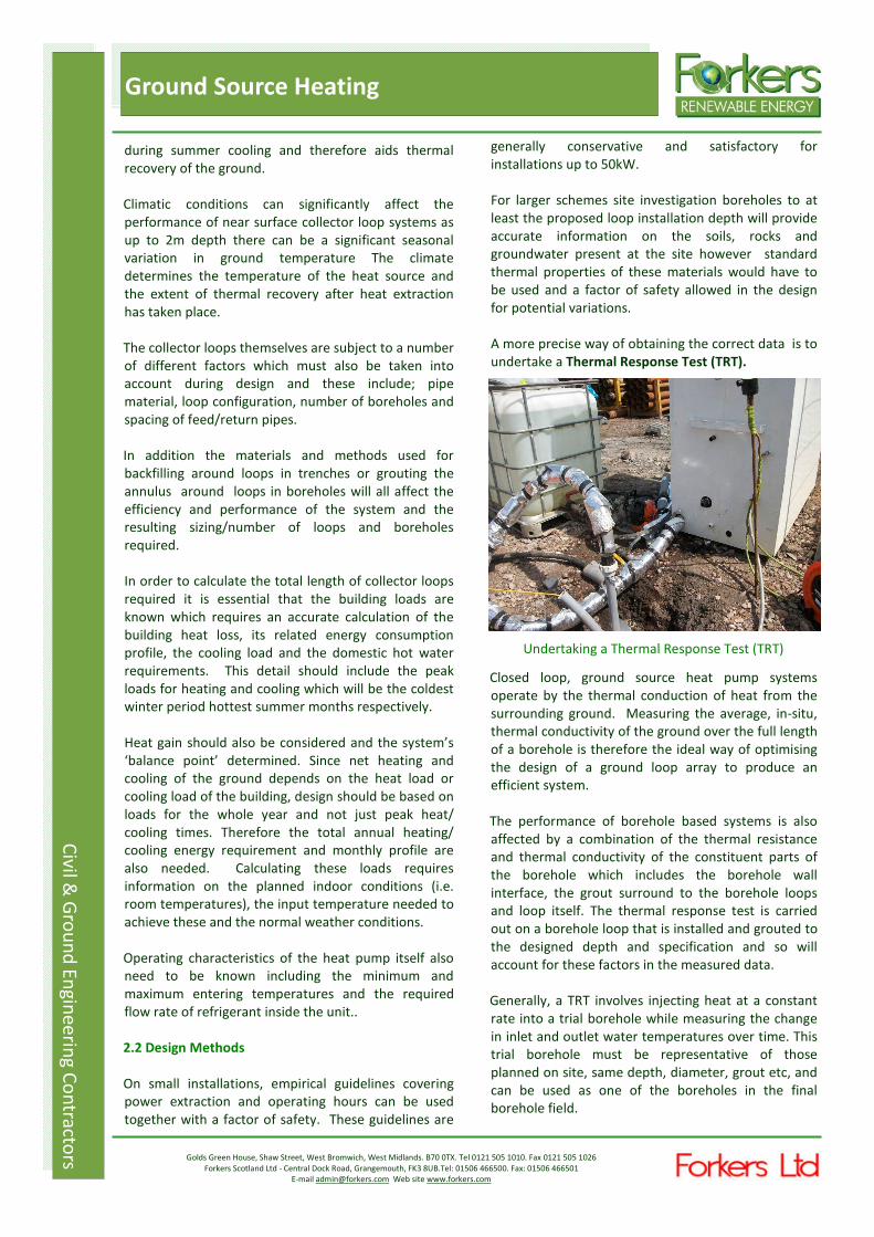
The heat pump uses a refrigerant and a compressor to
extract this low temperature heat energy and increase
it to a figure that is suitable for heating buildings.
Removing the heat from the circulating fluid reduces
its temperature back to about 0°C and it is then re-
circulated through the collector or borehole loops to
be reheated (Fig 1).
The heat pump unit contains two heat exchangers.
The first is the ‘evaporator’ and it contains an
evaporant to extract the heat from the circulating
fluid. The evaporant is then compressed to increase
it’s temperature to between 45°C and 65°C before
interfacing with the building’s heating system water in
a second heat exchanger, called the condenser, which
heats the water. The heated water is circulated
through the building and returned to the heat pump
at about 35°C. The evaporant is passed through an
Fig 1


Civil & Ground Engineerin
g Contracto
rs
Civil &
Gro
un
d E
ng
ine
erin
g C
on
tracto
rs
Golds Green House, Shaw Street, West Bromwich, West Midlands. B70 0TX. Tel 0121 505 1010. Fax 0121 505 1026
Forkers Scotland Ltd - Central Dock Road, Grangemouth, FK3 8UB.Tel: 01506 466500. Fax: 01506 466501
E-mail [email protected] Web site www.forkers.com
Ground Source Heating
expansion valve where it returns to its original pressure
and temperature.
In addition to building heating, the system will heat the
domestic hot water in the same way.
The energy needed to run a heat pump is significantly
less than that needed to heat a dwelling.
GSHP systems can also be ‘reversed’ by using a reverse
cycle heat pump to provide building cooling solutions
during summer months. In this configuration heat is
extracted from the building and put back in the ground.
This assists the temperature re-charge of the ground
around the loops and ensures the heat energy status
quo of the system is maintained.
The efficiency of GSHP systems is optimised by ensuring
heating and cooling loads are compatible with heat
pump selection and loop design and that the ground
loops or boreholes are properly installed.
1.3 Open Loop Ground Source Systems
Open loop systems can be installed in larger diameter
boreholes where permeable strata and high
groundwater flows exist, such as an aquifer, or in a
large water body such as a water filled mineshaft.
Groundwater from the ’well’ is extracted by suitably
sized borehole pump and passed through the heat
pump. The cooled water is re-circulated back to the
water source via a separate recharge well which will
sited some way from the abstraction point.
The groundwater inflow to the abstraction borehole
must be several times greater than the proposed
abstraction volume to ensure there is no significant
drawdown during operation and to ensure sufficient
groundwater flow is available to cater for the removal
of required heat energy. Open Loop systems require
regulatory approval from the Environment Agency as
they involve ‘abstraction’ of water.
1.4 Applications
Ground source systems are suitable for heating and
cooling as well as provision of domestic hot water for
any public, industrial, commercial and residential
buildings and can also be applied to a number of
industrial processes.
Heating and cooling arrangements will be designed to
suit the design of the building services and M&E
installation but may consist of radiators (convection),
ducted air or underfloor systems.
A dual heating and cooling GSHP installation powered
by a renewable energy source would be a fully
sustainable system.
2.0 Design of Closed Loop Systems —Introduction
The majority of systems installed are closed loop
arrangements.
Collector pipe arrays are normally placed in shallow
trenches of up to 2m depth. A reasonably large area
open land is required to provide the necessary area of
installation taking into account the spacing of feed and
return loops.
Some collector pipe systems are installed as coils or
’slinky’s’ in trenches although these installations are
not as efficient as separated feed and return loops.
Borehole based systems are generally installed up to
150m depth and most commonly at 100—120m and
may consist of one or several hundred boreholes
depending on the size of the building which, for
example, may range from individual houses to large
public buildings such as hospitals.
Fig 2—Borehole and Collector GSHP Systems
At a depth of 100m the temperature is about 12°C
increasing to about 15°C at 200m. The thermal
conductivity of different soils and rocks, however,
ranges from about 1 to 3 W/mK and a ground source
heating system cannot be operated for long periods at
high extraction rates without allowing the zones
surrounding the ground loops or boreholes to have a
temperature re-charge. This is normally allowed for in
a design by assuming a reduced loading in summer
months when only domestic hot water is being heated,
allowing thermal recharge from the surrounding
ground, or by design a cooling system to operate
during summer months which will provide direct
recharge to the ground surrounding the loops.


Business Descriptio n For kers Ltd
Civil & Ground Engineerin
g Contracto
rs
Ground Source Heating
Civil &
Gro
un
d E
ng
ine
erin
g C
on
tracto
rs
Golds Green House, Shaw Street, West Bromwich, West Midlands. B70 0TX. Tel 0121 505 1010. Fax 0121 505 1026
Forkers Scotland Ltd - Central Dock Road, Grangemouth, FK3 8UB.Tel: 01506 466500. Fax: 01506 466501
E-mail [email protected] Web site www.forkers.com
In the design of a GSHP system there are a number of
controlling factors that will determine the type of
system chosen and sizing the of GSHP;
♦ The heating or cooling load and which is the
dominant design factor - it is often the case that
in modern, well insulated buildings that the
cooling load is significantly higher than the
heating load
♦ The efficiency of the heating and cooling
arrangements in the building—radiators, ducted
air, underfloor etc which may be different if the
installation is retrofit or new
♦ Heat pump capacity
♦ Annual operating hours and full load hours
♦ The likely peak load on the system
♦ The geology and hydrology of the site
♦ The ambient ground temperature
♦ The thermal conductivity of the soils and rocks
and the resultant heat energy availability over
time
♦ The available space for installation of collector
loops or boreholes
♦ Possible future extensions to the buildings or
facilities
♦ Access for maintenance
Note: Standardised thermal properties of the soils
with a suitable factor of safety will be used unless a
site specific ’thermal response’ test has been carried
out to verify site conditions.
Installing Ground Source Loop in 100m deep
Borehole
The analysis of the above factors will determine the
heat pump capacity but will also lead to a decision on
whether;
♦ Horizontal ground collector loops
♦ Borehole collector loop systems or
♦ An open loop system—is used
2.1 Design and sizing of Collector Loops
Sizing the collector loop arrangement i.e. diameter,
depth, length and area coverage is one of the most
important aspect of the design of a GSHP system and
is crucial to achieving good performance. If the loop
arrangement is undersized it will result in poor
efficiency from the outset.
An undersized system will try and draw more heat
energy from the ground than it can sustain.
Temperature recovery is not achieved between
heating seasons and ground temperatures will
gradually decrease year on year. A long term effect
can also be that return fluid is below freezing and
sections of the ground near surface can become
frozen.
Heat pump designs need to balance long term issues
such as heat build up or depletion, while also catering
for short term peak loads (during which temperatures
can increase between 5°C and 10°C in 1 to 2 hours).
With an undersized collector loop arrangement there
is considerable risk of not being able to meet the
required building heating (or cooling) load.
Conversely, if the collector loop system is oversized,
the installation costs of the GSHP system will increase
and may make overall project costs unacceptable. A
bigger ground heat exchanger will result in increased
system capacity,
To optimise the size and length of the collector loops
all design parameters should be known and this is
where the information from a site specific thermal
response test can be invaluable in order to
understand the thermal gradient and temperature of
the ground and the thermal conductivity of the strata
which will determine the availability of the heat
energy to the collector loops for the particular
geological conditions of the site. The moisture
content/saturation of the ground will further affect
design considerations as this alters thermal
conductivity.
If these thermal properties are not properly measured
and understood, standard values must be used but
they should be used with caution and should include
factors of safety.
These risks on system sizing can be partially offset by
installing heat pump systems that offer both heating
and cooling since heat is returned to the ground

Business Descriptio n For kers Ltd
Civil & Ground Engineerin
g Contracto
rs
Ground Source Heating
Civil &
Gro
un
d E
ng
ine
erin
g C
on
tracto
rs
Golds Green House, Shaw Street, West Bromwich, West Midlands. B70 0TX. Tel 0121 505 1010. Fax 0121 505 1026
Forkers Scotland Ltd - Central Dock Road, Grangemouth, FK3 8UB.Tel: 01506 466500. Fax: 01506 466501
E-mail [email protected] Web site www.forkers.com
during summer cooling and therefore aids thermal
recovery of the ground.
Climatic conditions can significantly affect the
performance of near surface collector loop systems as
up to 2m depth there can be a significant seasonal
variation in ground temperature The climate
determines the temperature of the heat source and
the extent of thermal recovery after heat extraction
has taken place.
The collector loops themselves are subject to a number
of different factors which must also be taken into
account during design and these include; pipe
material, loop configuration, number of boreholes and
spacing of feed/return pipes.
In addition the materials and methods used for
backfilling around loops in trenches or grouting the
annulus around loops in boreholes will all affect the
efficiency and performance of the system and the
resulting sizing/number of loops and boreholes
required.
In order to calculate the total length of collector loops
required it is essential that the building loads are
known which requires an accurate calculation of the
building heat loss, its related energy consumption
profile, the cooling load and the domestic hot water
requirements. This detail should include the peak
loads for heating and cooling which will be the coldest
winter period hottest summer months respectively.
Heat gain should also be considered and the system’s
‘balance point’ determined. Since net heating and
cooling of the ground depends on the heat load or
cooling load of the building, design should be based on
loads for the whole year and not just peak heat/
cooling times. Therefore the total annual heating/
cooling energy requirement and monthly profile are
also needed. Calculating these loads requires
information on the planned indoor conditions (i.e.
room temperatures), the input temperature needed to
achieve these and the normal weather conditions.
Operating characteristics of the heat pump itself also
need to be known including the minimum and
maximum entering temperatures and the required
flow rate of refrigerant inside the unit..
2.2 Design Methods
On small installations, empirical guidelines covering
power extraction and operating hours can be used
together with a factor of safety. These guidelines are
generally conservative and satisfactory for
installations up to 50kW.
For larger schemes site investigation boreholes to at
least the proposed loop installation depth will provide
accurate information on the soils, rocks and
groundwater present at the site however standard
thermal properties of these materials would have to
be used and a factor of safety allowed in the design
for potential variations.
A more precise way of obtaining the correct data is to
undertake a Thermal Response Test (TRT).
Undertaking a Thermal Response Test (TRT)
Closed loop, ground source heat pump systems
operate by the thermal conduction of heat from the
surrounding ground. Measuring the average, in-situ,
thermal conductivity of the ground over the full length
of a borehole is therefore the ideal way of optimising
the design of a ground loop array to produce an
efficient system.
The performance of borehole based systems is also
affected by a combination of the thermal resistance
and thermal conductivity of the constituent parts of
the borehole which includes the borehole wall
interface, the grout surround to the borehole loops
and loop itself. The thermal response test is carried
out on a borehole loop that is installed and grouted to
the designed depth and specification and so will
account for these factors in the measured data.
Generally, a TRT involves injecting heat at a constant
rate into a trial borehole while measuring the change
in inlet and outlet water temperatures over time. This
trial borehole must be representative of those
planned on site, same depth, diameter, grout etc, and
can be used as one of the boreholes in the final
borehole field.

Business Descriptio n For kers Ltd
Civil & Ground Engineerin
g Contracto
rs
Ground Source Heating
Civil &
Gro
un
d E
ng
ine
erin
g C
on
tracto
rs
Golds Green House, Shaw Street, West Bromwich, West Midlands. B70 0TX. Tel 0121 505 1010. Fax 0121 505 1026
Forkers Scotland Ltd - Central Dock Road, Grangemouth, FK3 8UB.Tel: 01506 466500. Fax: 01506 466501
E-mail [email protected] Web site www.forkers.com
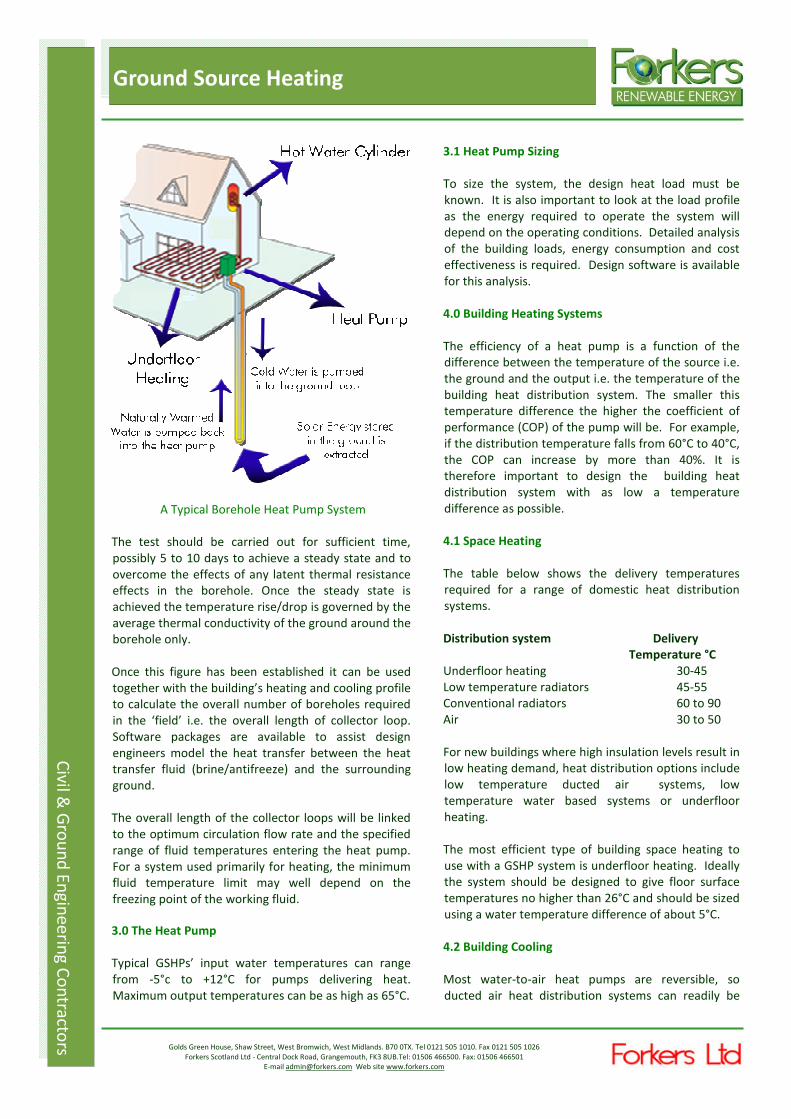
A Typical Borehole Heat Pump System
The test should be carried out for sufficient time,
possibly 5 to 10 days to achieve a steady state and to
overcome the effects of any latent thermal resistance
effects in the borehole. Once the steady state is
achieved the temperature rise/drop is governed by the
average thermal conductivity of the ground around the
borehole only.
Once this figure has been established it can be used
together with the building’s heating and cooling profile
to calculate the overall number of boreholes required
in the ‘field’ i.e. the overall length of collector loop.
Software packages are available to assist design
engineers model the heat transfer between the heat
transfer fluid (brine/antifreeze) and the surrounding
ground.
The overall length of the collector loops will be linked
to the optimum circulation flow rate and the specified
range of fluid temperatures entering the heat pump.
For a system used primarily for heating, the minimum
fluid temperature limit may well depend on the
freezing point of the working fluid.
3.0 The Heat Pump
Typical GSHPs’ input water temperatures can range
from -5°c to +12°C for pumps delivering heat.
Maximum output temperatures can be as high as 65°C.
3.1 Heat Pump Sizing
To size the system, the design heat load must be
known. It is also important to look at the load profile
as the energy required to operate the system will
depend on the operating conditions. Detailed analysis
of the building loads, energy consumption and cost
effectiveness is required. Design software is available
for this analysis.
4.0 Building Heating Systems
The efficiency of a heat pump is a function of the
difference between the temperature of the source i.e.
the ground and the output i.e. the temperature of the
building heat distribution system. The smaller this
temperature difference the higher the coefficient of
performance (COP) of the pump will be. For example,
if the distribution temperature falls from 60°C to 40°C,
the COP can increase by more than 40%. It is
therefore important to design the building heat
distribution system with as low a temperature
difference as possible.
4.1 Space Heating
The table below shows the delivery temperatures
required for a range of domestic heat distribution
systems.
Distribution system Delivery
Temperature °C
Underfloor heating 30-45
Low temperature radiators 45-55
Conventional radiators 60 to 90
Air 30 to 50
For new buildings where high insulation levels result in
low heating demand, heat distribution options include
low temperature ducted air systems, low
temperature water based systems or underfloor
heating.
The most efficient type of building space heating to
use with a GSHP system is underfloor heating. Ideally
the system should be designed to give floor surface
temperatures no higher than 26°C and should be sized
using a water temperature difference of about 5°C.
4.2 Building Cooling
Most water-to-air heat pumps are reversible, so
ducted air heat distribution systems can readily be

Business Description For kers Ltd
Civil & Ground Engineerin
g Contracto
rs
Ground Source Heating
Civil & Ground Engineerin
g Contracto
rs
Golds Green House, Shaw Street, West Bromwich, West Midlands. B70 0TX. Tel 0121 505 1010. Fax 0121 505 1026
Forkers Scotland Ltd - Central Dock Road, Grangemouth, FK3 8UB.Tel: 01506 466500. Fax: 01506 466501
E-mail [email protected] Web site www.forkers.com
Ground Source Heating
Civil &
Gro
un
d E
ng
ine
erin
g C
on
tracto
rs
adapted to provide cooling as well as heating. A
reversible water-to-water heat pump coupled to an
underfloor system can also be designed to provide
building space cooling in summer.
5.0 Installation of the Ground Collector Loops
The ground collector loops (sometimes referred to as
the ‘ground heat exchanger’ must be installed correctly
to work efficiently, this is especially important for
borehole based systems.
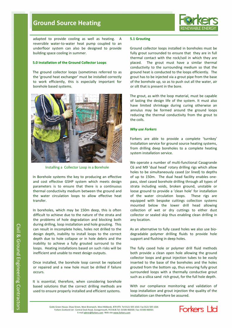
Installing a Collector Loop in a Borehole
In Borehole systems the key to producing an effective
and cost effective GSHP system which meets design
parameters is to ensure that there is a continuous
thermal conductivity medium between the ground and
the water circulation loops to allow effective heat
transfer.
In boreholes, which may be 150m deep, this is often
difficult to achieve due to the nature of the strata and
the problems of hole degradation and blocking both
during drilling, loop installation and hole grouting. This
can result in incomplete holes, holes not drilled to the
design depth, inability to install loops to the correct
depth due to hole collapse or in hole debris and the
inability to achieve a fully grouted surround to the
loops. Heating installations based on such risks will be
inefficient and unable to meet design outputs.
Once installed, the borehole loop cannot be replaced
or repaired and a new hole must be drilled if failure
occurs.
It is essential, therefore, when considering borehole
based solutions that the correct drilling methods are
used to ensure properly installed and efficient systems.
5.1 Grouting
Ground collector loops installed in boreholes must be
fully grout surrounded to ensure that they are in full
thermal contact with the rock/soil in which they are
placed. The grout must have a similar thermal
conductivity to the surrounding medium so that the
ground heat is conducted to the loops efficiently. The
grout has to be injected via a grout pipe from the base
of the borehole up, so as to push out all the water, air
or silt that is present in the bore.
The grout, as with the loop material, must be capable
of lasting the design life of the system. It must also
have limited shrinkage during curing otherwise an
annulus may be formed around the ground loops
reducing the thermal conductivity from the grout to
the coils.
Why use Forkers
Forkers are able to provide a complete ‘turnkey’
installation service for ground source heating systems,
from drilling deep boreholes to a complete heating
system installation service.
We operate a number of multi-functional Casagrande
C6 and M9 ‘dual head’ rotary drilling rigs which allow
holes to be simultaneously cased (or lined) to depths
of up to 150m. The dual head facility enables one-
pass, steel cased borehole drilling through all types of
strata including voids, broken ground, unstable or
loose ground to provide a ’clean hole’ for installation
of the water circulation loops. These rigs are
equipped with bespoke cuttings collection systems
mounted below the lower drill head allowing
collection of wet or dry cuttings to either dust
collector or sealed skip thus enabling clean drilling in
any location.
As an alternative to fully cased holes we also use bio-
degradable polymer drilling fluids to provide hole
support and flushing in deep holes.
The fully cased hole or polymer drill fluid methods
both provide a clean open hole allowing the ground
collector loops and grout injection tubes to be easily
inserted to the base of the boreholes and the holes
grouted from the bottom up, thus ensuring fully grout
surrounded loops with a thermally conductive grout
such as a silica sand rich grout, for the full hole depth.
With our compliance monitoring and validation of
loop installation and grout injection the quality of the
installation can therefore be assured.

Business Description For kers Ltd
Civil & Ground Engineerin
g Contracto
rs
Ground Source Heating
Civil & Ground Engineerin
g Contracto
rs
Golds Green House, Shaw Street, West Bromwich, West Midlands. B70 0TX. Tel 0121 505 1010. Fax 0121 505 1026
Forkers Scotland Ltd - Central Dock Road, Grangemouth, FK3 8UB.Tel: 01506 466500. Fax: 01506 466501
E-mail [email protected] Web site www.forkers.com
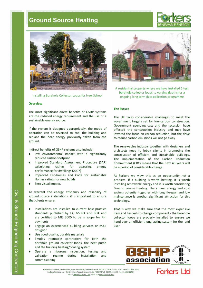
A residential property where we have installed 5 test
borehole collector loops to varying depths for a
ongoing long term data collection programme
The Future
The UK faces considerable challenges to meet the
government targets set for low-carbon construction.
Government spending cuts and the recession have
affected the construction industry and may have
lowered the focus on carbon reduction, but the drive
to reduce carbon emissions will not go away.
The renewables industry together with designers and
architects need to lobby clients in promoting the
construction of efficient and sustainable buildings.
The implementation of the Carbon Reduction
Commitment (CRC) means that the next 40 years will
be a period of considerable change.
At Forkers we view this as an opportunity not a
problem. If a building is worth heating, it is worth
installing renewable energy and it is worth considering
Ground Source Heating. The annual energy and cost
savings potential together with long life-span and low
maintenance is another significant attraction for this
technology.
That is why we make sure that the most expensive
item and hardest-to-change component - the borehole
collector loops are properly installed to ensure we
hand over an efficient long lasting system for the end
user.
Ground Source Heating
Civil & Ground Engineering Contractors
Installing Borehole Collector Loops for New School
Overview
The most significant direct benefits of GSHP systems
are the reduced energy requirement and the use of a
sustainable energy source.
If the system is designed appropriately, the mode of
operation can be reversed to cool the building and
replace the heat energy previously taken from the
ground.
Indirect benefits of GSHP systems also include:
♦ low environmental impact with a significantly
reduced carbon footprint
♦ Improved Standard Assessment Procedure (SAP)
calculating ratings for assessing energy
performance for dwellings (2007)
♦ Improved Eco-homes and Code for sustainable
Homes ratings for new builds
♦ Zero visual impact.
To warrant the energy efficiency and reliability of
ground source installations, it is important to ensure
that clients ensure;
♦ Installations are installed to current best practice
standards published by EA, GSHPA and BDA and
are certified to MIS 3005 to be in scope for RHI
payments
♦ Engage an experienced building services or M&E
designer
♦ Use good quality, durable materials
♦ Employ reputable contractors for both the
borehole ground collector loops, the heat pump
and the building heating/cooling system
♦ Operate a rigorous inspection, testing and
validation regime during installation and
commissioning


Meeting Renewable Heat Goals In The UK
Business Description For kers Ltd
Civil & Ground Engineerin
g Contracto
rs
Ground Source Heating
Civil & Ground Engineerin
g Contracto
rs
Golds Green House, Shaw Street, West Bromwich, West Midlands. B70 0TX. Tel 0121 505 1010. Fax 0121 505 1026
Forkers Scotland Ltd - Central Dock Road, Grangemouth, FK3 8UB.Tel: 01506 466500. Fax: 01506 466501
E-mail [email protected] Web site www.forkers.com
New guidance published by the Environment Agency,
the GSHPA and the BDA will support this energy
revolution in homes and businesses whilst also helping
to ensure high standards of installation and protection
of the environment.
Whether or not we agree with all of the assumptions
used in government forecasts there is a clear need for
massive investment and uptake of the technology for
this sort of growth to be achieved.
Ground Source Heating
Civil &
Gro
un
d E
ng
ine
erin
g C
on
tracto
rs
At present about two-thirds of the oil and gas burnt in
the UK is used for industrial and domestic heating. This
situation cannot continue indefinitely. The
governments National Renewable Energy Plan
estimates that the share of UK heat demand met by
renewable resources needs to increase from today’s 1%
to around 15% in 2020 to help the country meet its
overall target on renewable energy for that year.
Ground source heating and cooling (GSHC) schemes
play an important part in the mix of technologies that
will be needed to meet the 2020 target.
There are some 12,000 heat-pump installations in the
UK today and the EA forecast that there could be over
300,000 ground source heating installations by 2020.
The Government estimates that ground source heating
and cooling systems have the potential to provide up to
29 per cent of total UK built environment heat demand
by 2050.
For further details on Forkers Renewable Energy
Services please contact
Jane Sweeney—Business Development Manager
Forkers Renewable Energy
Golds Green House,
Shaw Street, West Bromwich
West Midlands.
B70 0TX.
t: 0121 505 1010
