a guide to 4k/uhd monitoring and...
TRANSCRIPT

TEK.COM/4K
A GUIDE TO 4K/UHD MONITORING AND MEASUREMENT––6 Key Challenges of 4K/UHD Content CreationeBook
2 | TEK.COM/4K
Introduction––The transition to 4K/UHD offers high resolution either (4096x2160) for cinematic distribution or (3840x2160) for distribution to the home. Enhanced viewing experience is possible with High Dynamic Range (HDR) and wider extended color gamut using ITU-R BT.2020 color space. This enhanced viewing experience offers viewers imagery that envelopes them within the scene.
A GUIDE TO 4K/UHD CONTENT CREATION

3 | TEK.COM/4K A GUIDE TO 4K/UHD CONTENT CREATION
File-basedStorage
Acquisition
Post-Production
To monitor the 4K/UHD signals the Tektronix 8000 series waveform monitor or rasterizer can be easily upgraded to support a wide variety of 4K/UHD formats in square division or two sample interleaved. Traditional tools like waveform, vector and gamut displays can be used in 4K/UHD for different color spaces such as ITU-R BT.2020 that provides extended color range for 4K content.
Producing 4K/UHD images start with acquisition from a high resolution camera that offers extended color gamut and high dynamic range to capture the image. On location larger high resolution images are saved to multiple disks for processing later. While in a studio or outside broadcast truck the signals are distributed as four links using 3G-SDI (Serial Digital Interface) for fast progressive formats such as 50p, 59.94p and 60p or HD-SDI for progressive signals from 23.98p to 30p. Inter-channel timing is critical to ensure that the quad links signals arrive at the end device and can be stitched back together correctly.

A GUIDE TO 4K/UHD CONTENT CREATION4 | TEK.COM/4K
CHALLENGE 1: Inter-Channel Timing for Quad Link 4K/UHD Signal .....................................................................5
CHALLENGE 2: Video Payload Identifier (VPID) Monitoring is More Important Than Ever .....................................8
CHALLENGE 3: Select the Correct Colorimetry ...................................................................................................16
CHALLENGE 4: Trying to Figure Out the Aspect Ratio Of Incoming 4K/UHD Content ........................................22
CHALLENGE 5: Higher Expectations for 4K/UHD Content Quality ......................................................................26
CHALLENGE 6: Transmission of 4K/UHD Content ...............................................................................................31
CONCLUSION .........................................................................................................................................................35
CONTENT
5 | TEK.COM/4K
CHALLENGE 1––INTER-CHANNEL TIMING FOR QUAD LINK 4K/UHD SIGNAL
A Quad Link 4K/UHD signal comprises of four SDI physical links. As these four signals are distributed along different transmission paths the delay along each path can be different. It is therefore important that when these signals are combined back together that they are correctly timed together.
A GUIDE TO 4K/UHD CONTENT CREATION6 | TEK.COM/4K
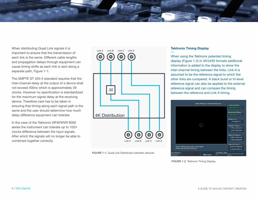
When distributing Quad Link signals it is important to ensure that the transmission of each link is the same. Different cable lengths and propagation delays through equipment can cause timing shifts as each link is sent along a separate path, Figure 1-1.
The SMPTE ST 425-5 standard requires that the inter-channel delay at the output of a device shall not exceed 400ns which is approximately 29 clocks. However no specification is standardized for the maximum signal delay at the receiving device. Therefore care has to be taken in ensuring that timing along each signal path is the same and the user should determine how much delay difference equipment can tolerate.
In the case of the Tektronix WFM/WVR 8000 series the instrument can tolerate up to 1024 clocks difference between the input signals. After which the signals will no longer be able to combined together correctly.
Link A Link B Link C Link D
Link A Link B Link C Link D
4K Distribution
Δt
FIGURE 1-1. Quad Link Distribution between devices.
FIGURE 1-2. Tektronix Timing Display.
Tektronix Timing Display--When using the Tektronix patented timing display (Figure 1-2) in 4K/UHD formats additional information is added to the display to show the inter-channel timing between the links. Link A is assumed to be the reference signal to which the other links are compared. A black burst or tri-level reference signal can also be applied to the external reference signal and can compare the timing between the reference and Link A timing.
A GUIDE TO 4K/UHD CONTENT CREATION7 | TEK.COM/4K
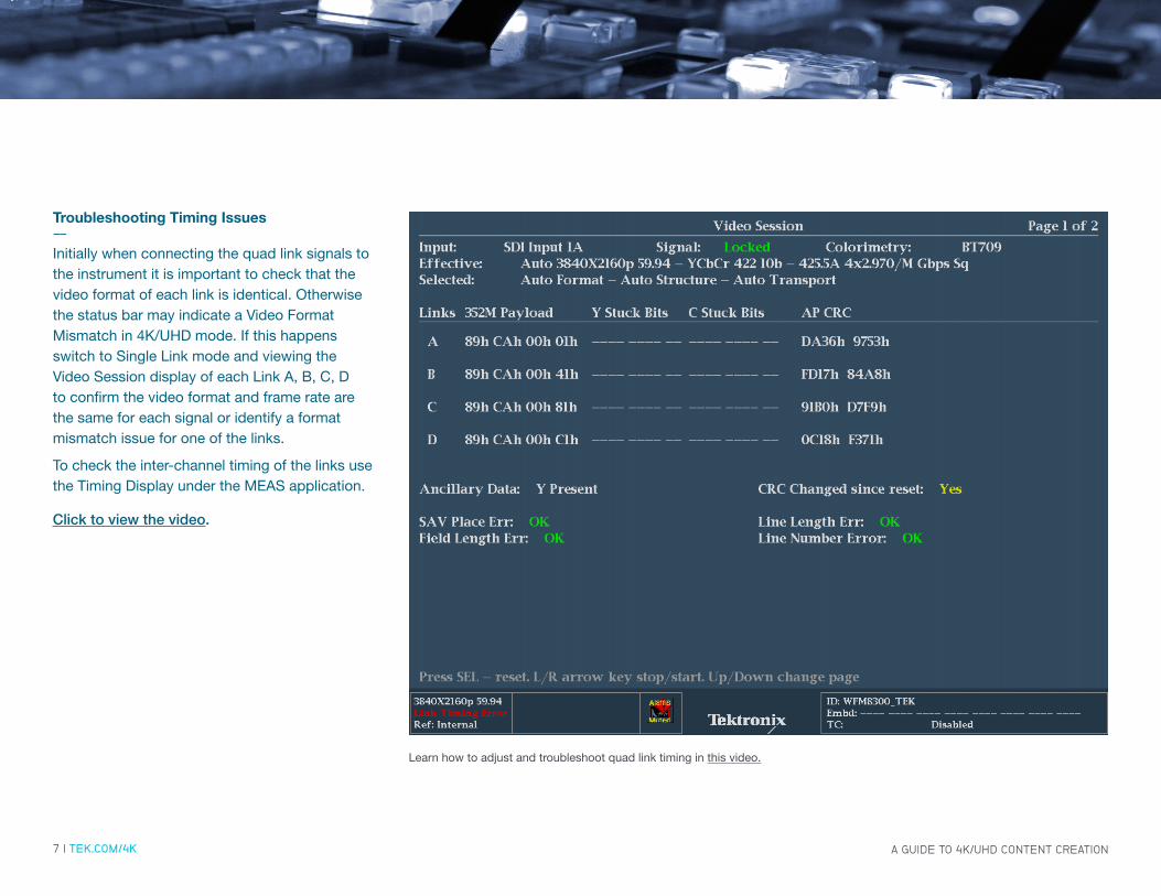
Troubleshooting Timing Issues--Initially when connecting the quad link signals to the instrument it is important to check that the video format of each link is identical. Otherwise the status bar may indicate a Video Format Mismatch in 4K/UHD mode. If this happens switch to Single Link mode and viewing the Video Session display of each Link A, B, C, D to confirm the video format and frame rate are the same for each signal or identify a format mismatch issue for one of the links.
To check the inter-channel timing of the links use the Timing Display under the MEAS application.
Click to view the video.
Learn how to adjust and troubleshoot quad link timing in this video.

8 | TEK.COM/4K
CHALLENGE 2––VIDEO PAYLOAD IDENTIFIER (VPID) MONITORING IS MORE IMPORTANT THAN EVER
With a wide variety of formats it is essential to use the SMPTE ST 352 Video Payload Identifier (VPID) that is carried within the ancillary data space to assist a device in quickly decoding the correct video format.

A GUIDE TO 4K/UHD CONTENT CREATION9 | TEK.COM/4K
The 8000 Series Waveform Monitors and Rasterizers can show the VPID within the Video Session display (Figure 2-3) and the data values can be found in the Ancillary Data Inspector or Datalist displays.
Note: Page 1 of the Video Session shows the VPID information as shown below.
The VPID conforms to the SMPTE 291 Ancillary Data Packet and Space Formatting standard and contains the Ancillary Data Flag (ADF), Data Identifier (DID), Secondary Data Identifier (SDID), Data Count, User Data Words (UDW 1-4) and Checksum.
FIGURE 2-3. Video Session Display showing Quad Link VPID FIGURE 2-4. Ancillary Data Display showing the four bytes of VPID information and the line and sample location of the current VPID packet.

A GUIDE TO 4K/UHD CONTENT CREATION10 | TEK.COM/4K
HEX B9 B8 B7 B6 B5 B4 B3 B3 B2 B1 B0
ADF
000 0 0 0 0 0 0 0 0 0 0 0
3FF 1 1 1 1 1 1 1 1 1 1 1
3FF 1 1 1 1 1 1 1 1 1 1 1
DID 241 not b8 EP 0 1 0 0 0 0 0 0 1
SDID 101 not b8 EP 0 0 0 0 0 0 0 0 1
DC 104 not b8 EP 0 0 0 0 0 0 1 0 0
UDW1 XXX not b8 EP Version ID Payload Identifier (see Table 2-2)
UDW2 XXX not b8 EP
Transport
Interlace 0
Progressive 1
Picture
Interlace 0
Progressive 1
Reserved
0
Reserved
0Picture Rate
(See Table 2-3)
UDW3 XXX not b8 EP
Reserved
01
Aspect Ratio
4:3 (0)
16:9 (1)
Reserved
02
Horz. Sampling
1920 (0)
2048 (1)
Reserved
03
Aspect Ratio
4:3 (0)
16:9 (1)
Reserved
0
(See Table 2-6)
Sampling
(See Table 2-4)
UDW4 XXX not b8 EP
Channel B7-B6 -B5
Single Link or
Multi-Channel
(See Table 2-5)
Reserved
0
Reserved
0
Reserved
0
Audio 3G SDI
(See Table 2-7)
Bit Depth
8-bit (0h)
10-bit (1h)
12-bit (2h)
Reserved (3h)
CS XXX not b8 EP Sum of B0-B8 of DID to Payload Byte 4 (UDW4)
Table 2-1. Video Payload Identifier Ancillary Data Packet
1 B7 used for Aspect Ratio in ST 425-1, 425-3 3G level A, 425-5 Quad Link 3G level A, 2081-10, 2082-10
2 B5 used for Aspect Ratio in ST 292, 372, 435-1. 425-5 3G level B, 3 Byte B7, B4 or B5-B4 Colorimetry Rec 709*1 (0h) Color VANC
Note Please refer to latest standard for complete details of VPID information.

A GUIDE TO 4K/UHD CONTENT CREATION11 | TEK.COM/4K
Table 2-2. SMPTE 352 Video Payload Identifier UDW 1For a complete list of Byte 1 registry http://smpte-ra.org/mdd/ST352-2011.html
Byte 1 Bit 0-7Standard Description
Decimal Hex129 81h SMPTE ST 259 Standard Definition (525i/625i) Signal/Data — 270Mb/s SDI
132 84h SMPTE ST 292-1 720-line video payloads for High Definition TV 1.5 Gb/s SDI
133 85h SMPTE ST 292-1 1080-line video payload High Definition TV 1.5 Gb/s SDI
135 87h SMPTE ST 372 Dual Link 1.5 Gb/s SDI for 1920 × 1080 Picture Formats
137 89h SMPTE ST 425-1 1080-line video payloads for 3 Gb/s Level A SDI
138 8Ah SMPTE ST 425-1 Dual-link (ST372) 1080-line for the 3 Gb/s Level B SDI
140 8Ch SMPTE ST 425-1 2 x 1080-line video payloads on a Level B 3 Gb/s
144 90h SMPTE ST 435-1 Quad-link 1080-line video payloads on a 10 Gb/s (nominal) serial digital (optical) interface
148 94h SMPTE ST 425-3 1080-line video payloads on a dual 3 Gb/s Level A SDI
149 95h SMPTE ST 425-3 1080-line video payloads on a dual 3 Gb/s Level B-DL SDI
150 96h SMPTE ST 425-3 2160-line video payloads on a dual 3 Gb/s Level B-DS SDI
151 97h SMPTE ST 425-5 2160-line video payloads on a quad 3 Gb/s Level A SDI
152 98h SMPTE ST 425-5 2160-line video payloads on a quad 3 Gb/s Level B-DL SDI
160 A0h SMPTE ST 435-1 Octa-link 2160-line video payloads on a 10 Gb/s (nominal) serial digital (optical) interface
161 A1h SMPTE ST 2036-3 UHDTV1 (4K image) — Mapping into Single-link or Multi-link 10 Gb/s SDI
162 A2h SMPTE ST 2036-3 UHDTV2 (8K image) — Mapping into Single-link or Multi-link 10 Gb/s SDI
165 A5h SMPTE ST 2036-4 UHDTV1 (4K image) video payloads on a multi-link 10 Gb/s SDI using multi-mode fiber
166 A6h SMPTE ST 2036-4 UHDTV2 (8K image) video payloads on a multi-link 10 Gb/s SDI using multi-mode fiber
179 B3h SMPTE ST 2048-3 4096×2160 Digital Cinematography Production Image Formats FS/709 on Multi-link 10 Gb/s SDI
192 C0h SMPTE ST 2081-10 Mode 1 2160-Line Source Image and Ancillary Data Mapping for Single-Link 6G-SDI
193 C1h SMPTE ST 2081-10 Mode 2 Carriage of 1080-line Source image formats and ancillary data in a single link 6G-SDI interface
194 C2h SMPTE ST 2081-11 Mode 1 Carriage of 1080-line Additional Frame Rates (AFR) in a single link 6G-SDI interface
196 C4h SMPTE ST 2081-12 Mode 1 Carriage of 4320-line Source image formats and ancillary data in a quad-link 6G-SDI
206 CEh SMPTE ST 2082-10 Mode 1 2160-line Source Image and Ancillary Data Mapping for 12G-SDI
207 CFh SMPTE ST 2082-10 Mode 2 Carriage of 1080-line Y’C’BC’R or R’G’B’ 4:4:4:4 10-bit or 4:4:4 10-bit or 12-bit Additional Frame Rate (AFR) for 12G-SDI

A GUIDE TO 4K/UHD CONTENT CREATION12 | TEK.COM/4K
Table 2-3. SMPTE 352 Picture Rate UDW2 B3-B0
Value Picture Rate0h No defined value
1h Reserved
2h 24/1.001
3h 24
4h 48/1.001
5h 25
6h 30/1.001
7h 30
8h 48
9h 50
Ah 60/1.001
Bh 60
Ch Reserved
Dh Reserved
Eh Reserved
Fh Reserved
Value Sampling Rate0h 4:2:2 (YCbCr)
1h 4:4:4 (YCbCr)
2h 4:4:4 (G/B/R)
3h 4:2:0
4h 4:2:2:4 (YCbCrA)
5h 4:4:4:4 (YCbCrA)
6h 4:4:4:4 (G/B/R/A)
7h SMPTE ST 2048-2 F-S
8h 4:2:2:4 (YCbCrD)
9h 4:4:4:4 (YCbCrD)
Ah 4:4:4:4 (G/B/R/D)
Bh Reserved
Ch Reserved
Dh Reserved
Eh Reserved
Fh Reserved
Table 2-4. SMPTE 352 Sampling Rate UDW3 B3-B0
Value Single or Multi-Link0h ch 1 multi-link (0h)
1h ch 2 multi-link (1h)
2h ch 3 multi-link (2h)
3h ch 4 multi-link (3h)
4h ch 5 multi-link (4h)
5h ch 6 multi-link (5h)
6h ch 7 multi-link (6h)
7h ch 8 multi-link (7h)
Table 2-5. SMPTE 352 Single or Multi-Link UDW4 B7-B5
Value Dual Link0h Dual-link A (0h)
1h Dual-link B (1h)
UDW4 B6
UDW4 B7-B6
Value Single or Multi-Link0h ch 1 multi-link (0h)
1h ch 2 multi-link (1h)
2h ch 3 multi-link (2h)
3h ch 4 multi-link (3h)

A GUIDE TO 4K/UHD CONTENT CREATION13 | TEK.COM/4K
The Tables 2-1 show the possible values for the payload Bytes 1-4 (UDW 0-3) of the SMPTE 352 payload ID. The user can use this information to help troubleshoot issues with the VPID. Note that different formats may uses some of the bit values differently depending on the format. For instance B7 of Byte 3 is used for Aspect Ratio in ST 425-1, 425-3 3G level A, 425-5 Quad Link 3G level A, 2081-10, 2082-10 standards. Whereas in the following standards ST 292, 372, 435-1. 425-5 3G level B, B5 of Byte 3 is used for Aspect Ratio. Additionally colorimetry information maybe present using B7, B4 or B5-B4 of Byte 3 depending on the standard used.
Troubleshooting VPID Issues--Quad Link can carry a wide variety of video formats and equipment can use the VPID to assist in determining the video format from the Ancillary data packet. This allows instruments like the Tektronix 8000 series waveform monitors and rasterizer to automatically determine the format of the video signal.
When the VPID is incorrect or multiple VPIDs are present in the same signal this can cause issues in processing equipment to correctly determine which ancillary packet to use.
By using the Video Session display the user can quickly check if the VPID is present and use the ANC Data Display and Datalist display to further investigate issues.
Table 2-7. SMPTE 352 Audio 3G SDI UDW4 B2
Value Audio 3G SDI0h Link 2 or 2 to 4 carries additional
channels or audio not present
1h Carries a copy of 3G-SDI Link 1 audio
Table 2-6. SMPTE 352 Colorimetry UDW3 B4 or B5-B4
Value Picture Rate0h Colorimetry Rec 709
1h Color VANC Packet
2h UHDTV
3h Unknown

A GUIDE TO 4K/UHD CONTENT CREATION14 | TEK.COM/4K
FIGURE 2-5. Video Session display showing Links swapped.
Troubleshooting VPID Issues--When in 4K/UHD mode, the status bar of the 8000 series instrument may show a Link Format Mismatch. For more information view the Video Session display to determine the problem Figure 2-5.
If the problem appears to be an issue of locking to the signal, it maybe necessary to switch the instrument to single mode and check the format of each link using the video session display to determine if one of the signals is not identical to the others. Once it has been determined that all signals are identical switch back to 4K mode and verify the VPID of each signal using the video session display.
Check the UDW words for each link. The first three bytes should be identical for each of the links. Byte 4 may also be identical if compliant to the single link format. However in 4K/UHD format the fourth byte should indicate the multi-link information to help the user identify if the links are swapped. Figure 2-5 shows in the Status bar that there is a Link Format Mismatch by checking the Video Session display. This display shows that the Links are swapped. In this case Byte 4 should have a sequence 01h, 41h, 81h and C1h indicating the multi-link information. Therefore link B and C are swapped and the signal path should be verified and the connections should be changed to correct the issue.
A GUIDE TO 4K/UHD CONTENT CREATION15 | TEK.COM/4K
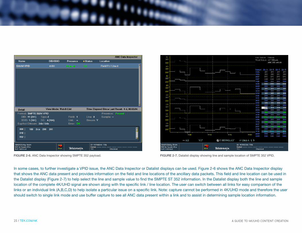
In some cases, to further investigate a VPID issue, the ANC Data Inspector or Datalist displays can be used. Figure 2-6 shows the ANC Data Inspector display that shows the ANC data present and provides information on the field and line locations of the ancillary data packets. This field and line location can be used in the Datalist display (Figure 2-7) to help select the line and sample value to find the SMPTE ST 352 information. In the Datalist display both the line and sample location of the complete 4K/UHD signal are shown along with the specific link / line location. The user can switch between all links for easy comparison of the links or an individual link (A,B,C,D) to help isolate a particular issue on a specific link. Note: capture cannot be performed in 4K/UHD mode and therefore the user should switch to single link mode and use buffer capture to see all ANC data present within a link and to assist in determining sample location information.
FIGURE 2-7. Datalist display showing line and sample location of SMPTE 352 VPID.FIGURE 2-6. ANC Data Inspector showing SMPTE 352 payload.
16 | TEK.COM/4K
CHALLENGE 3––SELECT THE CORRECT COLORIMETRY
4K/UHD can support either traditional HD colorimetry ITU-R BT.709 or the extended colorspace available in ITU-R BT.2020 to get higher color fidelity.
A GUIDE TO 4K/UHD CONTENT CREATION17 | TEK.COM/4K
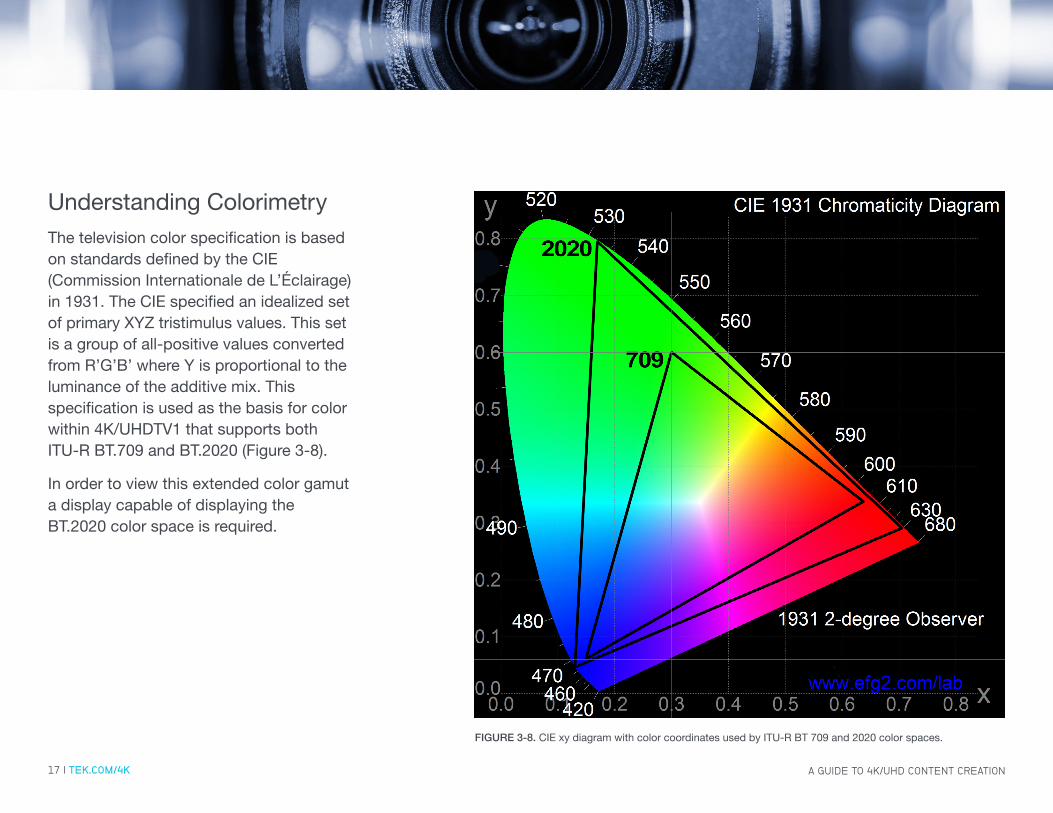
Understanding ColorimetryThe television color specification is based on standards defined by the CIE (Commission Internationale de L’Éclairage) in 1931. The CIE specified an idealized set of primary XYZ tristimulus values. This set is a group of all-positive values converted from R’G’B’ where Y is proportional to the luminance of the additive mix. This specification is used as the basis for color within 4K/UHDTV1 that supports both ITU-R BT.709 and BT.2020 (Figure 3-8).
In order to view this extended color gamut a display capable of displaying the BT.2020 color space is required.
FIGURE 3-8. CIE xy diagram with color coordinates used by ITU-R BT 709 and 2020 color spaces.
A GUIDE TO 4K/UHD CONTENT CREATION18 | TEK.COM/4K
Gamut Illuminant Red Green Blue
ITU-R BT. 2020 D65 x=0.708 y = 0.292 0.170 y= 0.797 x = 0.131 y = 0.046
ITU-R BT. 709 D65 x = 0.640 y = 0.330 x = 0.300 y = 0.600 x = 0.150 y = 0.060
SMPTE 431-2
(DCI-P3) XYZx = 0.680 y= 0.320 x = 0.265 y= 0.690 x = 0.150 y = 0.060
SMPTE D65 x = 0.630 y = 0.340 x = 0.310 y = 0.595 x = 0.155 y = 0.070
PAL/SECAM D65 x = 0.640 y = 0.330 x = 0.290 y = 0.600 x = 0.150 y = 0.060
NTSC C x = 0.670 y = 0.330 x = 0.210 y = 0.710 x = 0.140 y = 0.080
Rec. 601 Rec. 709 Rec. 2020
Y 0.299R’ + 0.587G’ + 0.114B’ 0.2126R’ + 0.7152G’ + 0.0722B’ 0.2627R’ + 0.6780G’ 0.0593B’
Pb (B’ - Y’)/ 1.772 (B’ - Y’)/ 1.8556 (B’ - Y’)/ 1.8814
Pr (R’ - Y’)/ 1.402 (R’ - Y’)/ 1.5748 (R’ - Y’)/ 1.4746
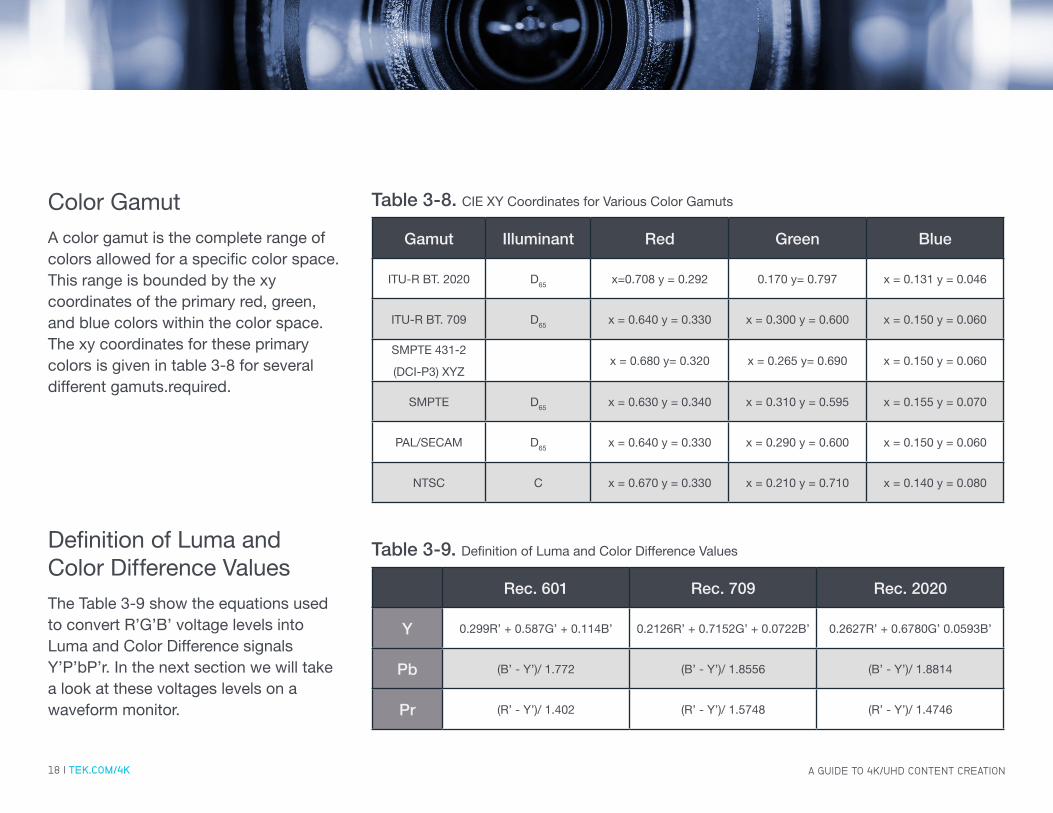
Table 3-8. CIE XY Coordinates for Various Color Gamuts
Table 3-9. Definition of Luma and Color Difference Values
Color GamutA color gamut is the complete range of colors allowed for a specific color space. This range is bounded by the xy coordinates of the primary red, green, and blue colors within the color space. The xy coordinates for these primary colors is given in table 3-8 for several different gamuts.required.
Definition of Luma and Color Difference ValuesThe Table 3-9 show the equations used to convert R’G’B’ voltage levels into Luma and Color Difference signals Y’P’bP’r. In the next section we will take a look at these voltages levels on a waveform monitor.

A GUIDE TO 4K/UHD CONTENT CREATION19 | TEK.COM/4K
Troubleshooting Colorimetry Issues--To understand color let’s look at a 100% color bar signal that has two states for the video levels 100% (700mv) and 0% (0mv) for each color component RGB (Red, Green and Blue). The waveform monitor shows (Figure 3-9) the video level transitions that make up all the combination of colors for the color bar signal Figure 3-11 (White, Yellow, Cyan, Green, Magenta, Red, Blue and Black).
The different equations used for the various color standards (Rec. 601, Rec. 709 and Rec.2020) produce different levels for each of the component signals in Y’P’bP’r as shown in the series of YPbPr waveform monitor displays.
Firstly notice the small spikes in the RGB waveform parade (Figure 3-9). This is due to the unequal rise time between Luma and Color Difference bandwidths and the conversion of SDI Y’P’bP’r back to R’G’B’ in the waveform display.
Secondly in the Green/Magenta transition between SD (Standard Definition Figure 3-10) and HD (High Definition Figure 3-12), there is a much larger transition in HD compared to SD. This is due to the difference in equations described in Definition of Luma and Chroma Difference Values previously.
FIGURE 3-9. Standard Definition 100% color bar RGB parade.
FIGURE 3-11. Standard Definition 100% color bar test pattern.
FIGURE 3-10. Standard Definition 100% color bar YPbPr parade.
FIGURE 3-12. High Definition 100% color bar YPbPr parade.

A GUIDE TO 4K/UHD CONTENT CREATION20 | TEK.COM/4K
Troubleshooting Colorimetry Issues--Now let’s take a look at the difference between HD using Rec. 709 and 4K/UHD which can use both Rec. 709 and Rec. 2020.
Firstly compare the HD signal in Figure 3-13 to the UHD signal in Figure 3-14. Notice the spike transitions in the UHD 100% color bar waveform display. This is normal and due to the fact that no video filtering is applied to each link. This allows the quad links to be seamlessly stitched together to form the 4K/UHD image otherwise a thin black line would be seen between the links.
You can compare the difference in levels between Rec. 709 (Figure 3-13 (HD), Figure 3-14 (UHD)) and Rec. 2020 (Figure 3-15 (UHD)). There are slight difference in the video levels as shown in Figure 3-16 which is a split field 100% color bar signal with both 709 and 2020 color spaces. Care has to be taken to chose the correct colorspace.
FIGURE 3-13. HD 100% color bars YPbPr parade, Rec. 709.
FIGURE 3-15. UHD 100% Color Bars YPbPr parade, Rec. 2020.
FIGURE 3-14. UHD 100% color bars YPbPr parade, Rec. 709.
FIGURE 3-16. UHD 100% Split Field Color Bars with both 709 and 2020 colorspaces in YPbPr Parade display.

A GUIDE TO 4K/UHD CONTENT CREATION21 | TEK.COM/4K
FIGURE 3-17. RGB Paraded waveform display of 100% Color Bar split field test signal with Rec. 709 and Rec. 2020 colorspaces.
Determining the correct color space--In some cases the SMPTE 352 VPID may contain information on the colorimetry data that is used. Then this information can be used by the Tektronix 8000 series waveform monitor or rasterizer to automatically use the appropriate colorspace. Often however, this may not be the case and a known test signal such as color bars will be necessary to assist the user in determining the correct color space.
In Figure 3-17 a 100% split field color bar signal containing both Rec. 709 and Rec. 2020 color spaces is used to show the difference in levels on the RGB paraded waveform display. The user must manually select from the configuration menu between the 709 and 2020 colorspaces. When the correct colorspace is selected then the traces will be at 0% and 100% (700mv) levels. If the incorrect colorspace is chosen then there will be variations in level of the signal and not all the color bars will lie at the 0% and 100% levels.

22 | TEK.COM/4K
CHALLENGE 4––TRYING TO FIGURE OUT THE ASPECT RATIO OF INCOMING 4K/UHD CONTENT
To check whether the 4K/UHD content was scanned and matted correctly for the proper aspect ratio could be a daunting task.

A GUIDE TO 4K/UHD CONTENT CREATION23 | TEK.COM/4K
Aspect RatioThe ratio of the horizontal size to the vertical size of the image.
For instance HD can have an image size of 1920 pixels horizontally by 1080 lines vertically.
This produce an aspect ratio of:
1920 = 1.778 = 16:9 1080
The aspect ratio for film and digital cinema are different typically having aspect ratios of 1.85:1 or 2:39:1 which are then fitted into images sizes of 4096x2160, 3840x2160, 2048x1080 or 1920x1080 depending on the application (Table 4-10).
Aspect Ratio Image Size Active Pixels Active Lines
1.33:1 (4:3) 720x480 (SD NTSC) 720 486
1.33:1 (4:3) 720x576 (SD PAL) 720 576
1.778:1 (16:9) HD (720) 1280 720
1.778:1 (16:9) HD (1080) 1920 1080
1.33:1 (4:3) HD(1080) 1440 1080
1.896:1 HD (2K) 2048 1080
1.85:1 HD (2K) 1998 1080
2.39:1 HD(2K) 2048 858
1.778:1 (16:9) UHD 3840 2160
1.896:1 4K 4096 2160
1.85:1 4K 3996 2160
2.39:1 4K 4096 1716
Table 4-10. Aspect Ratio for various image sizesNote: Standard Definition (SD) uses non square pixels.

A GUIDE TO 4K/UHD CONTENT CREATION24 | TEK.COM/4K
Determining Correct Aspect Ratio--During the film scanning or other image conversion processes the image may become distorted or cropped. Therefore it is important to ensure the correct aspect ratio of the image.
To perform this task it is necessary to check the start and end of the active picture both horizontally and vertically. This can be done either in the waveform displays using line select and magnification or by using datalist with line select and sample cursor.
For instance if the user wishes to check the aspect ratio of 1.85:1 of 4K content. Then the image size will be 3996x2160. The first active line will be at line number 83 (A0) Figure 4-18 and the end of the active image will be at line number 2242 (A2159) Figure 4-19. If the pictured is centered then the first active pixel Y sample should be at sample 50.AY Figure 4-20 and the last active pixel should be at sample 4045DY Figure 4-21. In this case Y waveform and line select were used to check the start and end of active picture and Datalist was used to check the start and end of active pixels in the image as shown in the pictures from the WFM8300. To simplify this process presets can be used to set up default positions for verifying the aspect ratio of the image.
FIGURE 4-20. Datalist display of first active sample FIGURE 4-21. Datalist display of last active sample.
FIGURE 4-18. Line Select mode showing first active line FIGURE 4-19. Tile 1 show line select mode of last active line.
A GUIDE TO 4K/UHD CONTENT CREATION25 | TEK.COM/4K
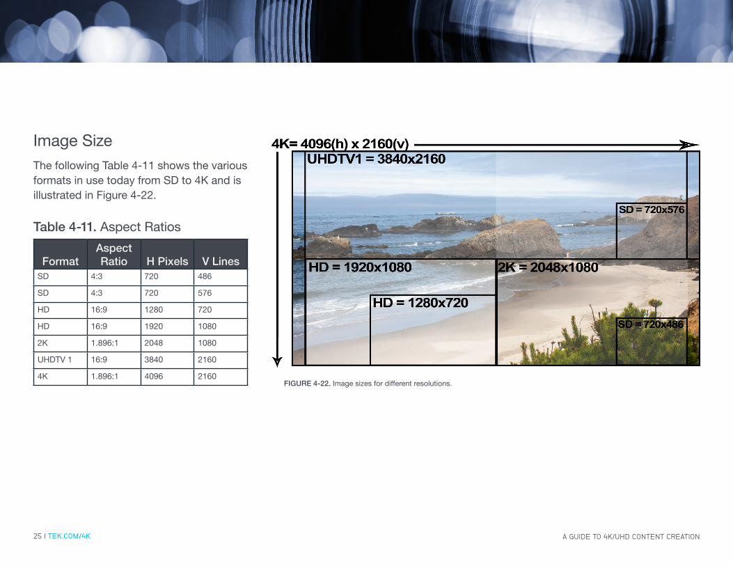
FormatAspect Ratio H Pixels V Lines
SD 4:3 720 486
SD 4:3 720 576
HD 16:9 1280 720
HD 16:9 1920 1080
2K 1.896:1 2048 1080
UHDTV 1 16:9 3840 2160
4K 1.896:1 4096 2160
Image SizeThe following Table 4-11 shows the various formats in use today from SD to 4K and is illustrated in Figure 4-22.
FIGURE 4-22. Image sizes for different resolutions.
Table 4-11. Aspect Ratios
26 | TEK.COM/4K
CHALLENGE 5––HIGHER EXPECTATIONS FOR 4K/UHD CONTENT QUALITY
Tight Quality Control (QC) of Luma and Chroma gamut is needed for 4K/UHD content QC as expectations are higher than ever to maintain compliance without sacrificing the artistic intent of the image.

A GUIDE TO 4K/UHD CONTENT CREATION27 | TEK.COM/4K
Quality ControlWhen the program is finally assembled the operator needs to ensure that the video and audio meet the specified delivery specifications. This will involve setting up the specified thresholds within the waveform monitor or rasterizer to trigger an alarm if these values are exceeded. These errors can then be logged within the Error Log of the instrument and related to timecode to allow the user to easily locate the error. An error log can also be downloaded from the instruments and sent along with the content, allowing the editor to quickly resolve any issues found in the material.
FIGURE 5-23. Four tile display showing quality assurance monitoring of video and audio with waveform, error log loudness session and audio displays.
A GUIDE TO 4K/UHD CONTENT CREATION28 | TEK.COM/4K
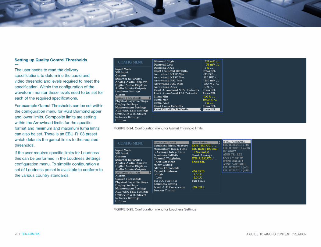
Setting up Quality Control Thresholds--The user needs to read the delivery specifications to determine the audio and video threshold and levels required to meet the specification. Within the configuration of the waveform monitor these levels need to be set for each of the required specifications.
For example Gamut Thresholds can be set within the configuration menu for RGB Diamond upper and lower limits. Composite limits are setting within the Arrowhead limits for the specific format and minimum and maximum luma limits can also be set. There is an EBU-R103 preset which defaults the gamut limits to the required thresholds.
If the user requires specific limits for Loudness this can be performed in the Loudness Settings configuration menu. To simplify configuration a set of Loudness preset is available to conform to the various country standards.
FIGURE 5-24. Configuration menu for Gamut Threshold limits
FIGURE 5-25. Configuration menu for Loudness Settings

A GUIDE TO 4K/UHD CONTENT CREATION29 | TEK.COM/4K
Setting up Alarm Configuration--After the user has set up the individual threshold limits for the required delivery specification, then each alarm should be set within the alarm configuration menu.
For example the Video Content alarms allows monitoring of the RGB Gamut, Composite Gamut and Luma Gamut. The user can set monitor of alarms to be On Screen Text, Logging to the error log, Beep, SNMP Trap or Ground Closure for each type of alarm.
The tick boxes show alarms currently being monitored. There are a wide variety of alarms and the user should configure those which are required to be monitored for the delivery specification. Once configured the user should save this configuration as a preset for easy recall of the settings and configuration.
FIGURE 5-26. Configuration menu for Alarm settings
FIGURE 5-27. Configuration menu for Video Content alarms.

A GUIDE TO 4K/UHD CONTENT CREATION30 | TEK.COM/4K
Quality Control Monitoring--Once the threshold levels and alarms are configured within the instrument the user can begin quality control monitoring of the content.
If the material has timecode present then the user should select to enable timecode monitoring within the configuration menu. This will then be shown in the status bar and the Error Log display.
Then the content can be monitored by the waveform monitor and errors found in the content will be logged via the instrument. When the content has finished the operator can review the Error Log to determine any errors within the content. By using timecode the operator or editor can quickly go to specific content to review the material in question.
The error log can also be downloaded from the instrument or saved to USB device and sent to the production company or editor to assist in determining the errors within the content.
FIGURE 5-28. Error Log displays show alarm values related to timecode and internal time.
31 | TEK.COM/4K
CHALLENGE 6––TRANSMISSION OF 4K/UHD CONTENT
The quad link signals data can be transmitted as Square Division or Two-Sample Interleaved depending on the application.

A GUIDE TO 4K/UHD CONTENT CREATION32 | TEK.COM/4K
HANCEAV
SAV
HANCEAV
SAV
HANCEAV
SAV
HANCEAV
SAV
Transmission & Distribution The way in which the 4K/UHD image is split apart into the quad links can be achieved by Square Division (Figure 6-29) where the image is divided into four quadrants. Each quadrant of the image is then encapuslated into an individual SDI signal. This is the simplest way to segment the image but requires more memory to store each of the quadrants before assembling the complete image. This method is commonly used by a variety of post-production equipment.
FIGURE 6-29. Square Divsion process of separating the 4K/UHD image into quad link signals.

A GUIDE TO 4K/UHD CONTENT CREATION33 | TEK.COM/4K
HANCEAV
SAV
HANCEAV
SAV
HANCEAV
SAV
HANCEAV
SAV
Transmission & Distribution Another way in which the 4K/UHD image is split apart into the quad links is to use Two Sample Interleave. In this process groups of two pixels are separated from the image and sent on four different links as shown in Figure 6-30. This method requires less memory to be used and allows groups of pixels to be processed more quickly. However this process requires multiplexing of the data into four separate SDI streams. Two-Sample Interleaving is typically used within the transmission process.
FIGURE 6-30. Two-Sample Interleave process of separating the 4K/UHD image into quad link signals.

A GUIDE TO 4K/UHD CONTENT CREATION34 | TEK.COM/4K
FIGURE 6-31. Configuration menu Quad SDI Mode.
Transport Configuration--There are no bytes used in SMPTE ST352 to indicate the transport mode of Square Division or Two Sample Interleave. Therefore in the 8000 series waveform monitors to determine the transport mode the instrument uses the VPID information and the standard used to automatically select Tile or Two Sample Interleave mode. Alternatively the user can force the Quad SDI mode within the configuration menu. The user can use the picture display to verfiy the correct mode has been selected and the image is assembled correctly.

35 | TEK.COM/4K
CONCLUSION––YOU’RE MAKING HIGH QUALITY CONTENT. TOGETHER, WE CAN ENSURE YOU GET IT RIGHT THE FIRST TIME.
A GUIDE TO 4K/UHD CONTENT CREATION36 | TEK.COM/4K
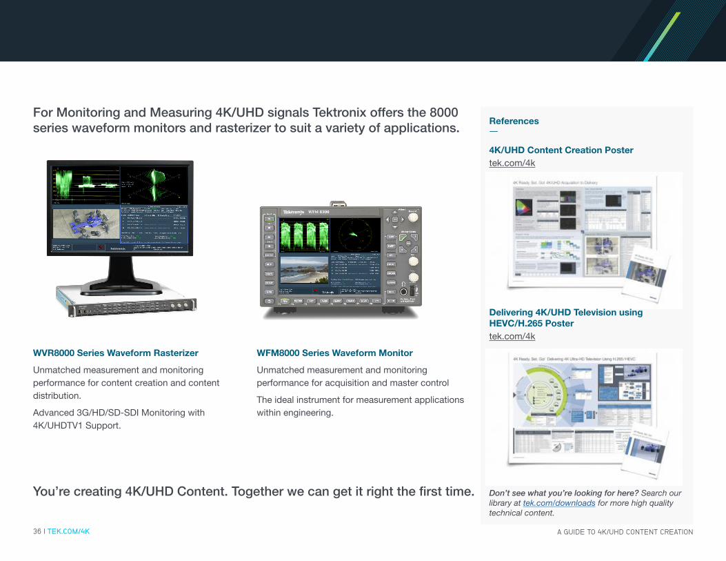
WFM8000 Series Waveform Monitor
Unmatched measurement and monitoring performance for acquisition and master control
The ideal instrument for measurement applications within engineering.
WVR8000 Series Waveform Rasterizer
Unmatched measurement and monitoring performance for content creation and content distribution.
Advanced 3G/HD/SD-SDI Monitoring with 4K/UHDTV1 Support.
You’re creating 4K/UHD Content. Together we can get it right the first time.
For Monitoring and Measuring 4K/UHD signals Tektronix offers the 8000 series waveform monitors and rasterizer to suit a variety of applications.
References--
Don’t see what you’re looking for here? Search our library at tek.com/downloads for more high quality technical content.
4K/UHD Content Creation Postertek.com/4k
Delivering 4K/UHD Television using HEVC/H.265 Postertek.com/4k
Contact Information: Australia 1 800 709 465
Austria 00800 2255 4835
Balkans, Israel, South Africa and other ISE Countries +41 52 675 3777
Belgium 00800 2255 4835
Brazil +55 (11) 3759 7627
Canada 1 800 833 9200
Central East Europe / Baltics +41 52 675 3777
Central Europe / Greece +41 52 675 3777
Denmark +45 80 88 1401
Finland +41 52 675 3777
France 00800 2255 4835
Germany 00800 2255 4835
Hong Kong 400 820 5835
India 000 800 650 1835
Indonesia 007 803 601 5249
Italy 00800 2255 4835
Japan 81 (3) 6714 3010
Luxembourg +41 52 675 3777
Malaysia 1 800 22 55835
Mexico, Central/South America and Caribbean 52 (55) 56 04 50 90
Middle East, Asia, and North Africa +41 52 675 3777
The Netherlands 00800 2255 4835
New Zealand 0800 800 238
Norway 800 16098
People’s Republic of China 400 820 5835
Philippines 1 800 1601 0077
Poland +41 52 675 3777
Portugal 80 08 12370
Republic of Korea +82 2 6917 5000
Russia / CIS +7 (495) 6647564
Singapore 800 6011 473
South Africa +41 52 675 3777
Spain 00800 2255 4835
Sweden 00800 2255 4835
Switzerland 00800 2255 4835
Taiwan 886 (2) 2656 6688
Thailand 1 800 011 931
United Kingdom / Ireland 00800 2255 4835
USA 1 800 833 9200
Vietnam 12060128
Rev. 020916
Find more valuable resources at TEK.COM
Copyright © 2016, Tektronix. All rights reserved. Tektronix products are covered by U.S. and foreign patents, issued and pending. Information in this publication supersedes that in all previously published material. Specification and price change privileges reserved. TEKTRONIX and TEK are registered trademarks of Tektronix, Inc. All other trade names referenced are the service marks, trademarks or registered trademarks of their respective companies. 02/16 EA 25W–60401-0