a group company bulletin 130c minster. minster’s cast ... removable bronze saddle bushings. all p2...
TRANSCRIPT

P2PIECE-MAKER60-200 TONS CAPACITY
HIGH PERFORMANCE COMBINED WITH DURABILITY RELIABILITYAND SERVICEABILITY IN STRAIGHT SIDE PRECISION PRESSES
P2 Series Presses
BULLETIN 130C
MINSTER®
A Group Company

P2 PIECE-MAKER
INTROAutomatic Straight Side Presses
002
002P2 Series Presses
Every operation involved in the building of aMinster Piece-Maker® press, from pouring ofcastings to final inspection, is based upon thedetermination to build the finest precisionpress. Because of this tradition, a MinsterPiece-Maker gives superior performance,greater accuracy, higher production andlonger die life, even under the most severeoperating conditions.
Parallelism between bolster and slide face ischecked to determine that the precisionalignment required on Piece-Maker presseshas been maintained throughout all stages ofconstruction. Also, vertical angularity of theslide throughout its entire stroke is checked leftto right and front to back. This kind of built-inquality is responsible for precision diealignment so necessary for successfulprogressive die stamping.

003
003P2 Series Presses
∂
∑
∏
π
∫ ª
º
æ
Ω

004
004P2 Series Presses
P2 PIECE-MAKER
STANDARD FEATURESCast Construction Reduces Vibration.Minster Piece-Maker P2 Series automatic production pressesare of high tensile cast iron construction. Parts sections are properlyproportioned for greatest strength without internal stresses. Variousalloys are used for different cast parts depending upon theirfunction. Minster’s cast construction is highly efficient in providingthe compressive strength and vibration dampening requirements soessential in building a precision press for progressive die work --particularly on heavy blanking jobs having high fracture loads. Youget less punch wear, better die life and more part accuracy becausethe vibration is held to a minimum in a Minster Piece-Maker.
Massive Bed Has Exceptional Rigidity. The superior design and quality construction of the P2 bed gives ithe lowest possible deflection charac-teristics under constant impactand heavy load conditions to maximize tool life and part quality. Oiltroughs help contain die lubricants for recycling.
Crown and Eccentric Shaft ProvideStrength and Resist Deflection.The massive crown of the Minster Piece-Maker is engineeredto maximize die life and part quality. Deep crown design backs upthe eccentric shaft at any angle against forces created by thestamping application. Close-coupled load carrying plates evenlydistribute these forces into the crown structure.
The forged steel eccentric shaft resists torsional and bendingdeflection to enhance die parallelism. It is machined to a superbfinish for excellent bearing fits and reduced stresses. The eccentricshaft eliminates the unsupported areas between main andconnection bearings caused by the cheek thickness of the normalcrankshaft. P2’s come standard with one extension.
The main bearings of the P2 press give exceptional supportto the eccentric shaft. Bearings are line bored for precise alignment.Crankshaft counterweights are standard on all flywheel drive P2’s.
Tie Rods Aid Rigidity. Four-piece tie rod construction is used in all MinsterP2 frames. Massive steel tie rods are pre-stressed tosolidly hold the frame against off-center loadingfrom progressive dies.
Main Bearing Support Block.This wedge-type support block is precision fittedbetween the main bearing caps and the top of theuprights. These supports help relieve the stressesplaced on bearing cap screws by snap-thru forcesand add to die life by stabilizing punch penetration.
∂
∑
∏
π
Eccentric Shaft
Normal Crankshaft
L+2T
L
L=Distance Between BearingsT=Thickness of Cheek

005
005P2 Series Presses
P2 PIECE-MAKER
STANDARD FEATURES
PRESS SIZE P2-60 P2-100 P2-150 P2-200 SLIDE ADJUSTMENT METHOD Flywheel Flywheel Geared Flywheel Geared Flywheel Geared Arranged for Detachable Air Wrench STD. STD. STD. Option Option Option Option Built-In ELECTRIC Motorized N/A Option Option STD. STD. STD. STD. Double Lock-Up w/Manual Adjustment Option Option N/A Option N/A Option N/A
Shutheight Adjustment & Indication.Included as standard is an electronic encoder mounted on the slidethat sends a digital readout to the PMC display. This feature aids theoperator in accurate die setting procedures. The P2 offers poweredslide adjustment for operator ease.
Heavy Slide and Connections.The P2 slide is of deep, heavily reinforced box-type construction, designed to withstand deflection to promote part quality and provide alarge die area within the gibs. The massive upper connections easilytransmit pressure through the working stroke. Lower connections haveremovable bronze saddle bushings. All P2 slides are arranged for onecross bar knockout as standard.
8-Point Gibbing for Precision Slide Guiding.Precision slide guiding is maintained by the close-tolerance 8-point gibbingarrangement. Front and rear gibs are accurately squared with the press bedand set for proper clearance by laminated spacers under each main gib bolt . . .thus eliminating trial and error adjustment.
Front to back ways have fixed bronze wear plates, machined squarewith the slide face. Left to right ways are adjusted and supported their fulllength by tapered back-up bars. The extra-long gibs guide the slide fullywithin the gibs throughout the stroke -- even at maximum shutheightadjustments. This assures excellent slide-to-bed parallelism at all times,contributing to clean material fracture, high part accuracy, and increased dielife. Slide and bolster are machined with standard T-Slots.
∫
º
ª
Flywheel type presses run at higher speeds and have shorter strokesfor punching, notching, blanking and shallow forming or drawingoperations on lighter materials. The Clutch and Brake Unit is mountedon the eccentric shaft within the flywheel. Flywheel rotates on anti-friction bearings. Flywheel brake is electrically interlocked with drive“Stop” circuit to eliminate “coasting.”
Drive Arrangements for Maximum Press Efficiency.
Geared Drive
Flywheel Drive
Geared Drive Motor is on rear as shown.
Ω
Single Geared P2 presses incorporatehelical gears for quiet operation, heaviermaterial blanking, punching and deeperforming or drawing operations. The Clutchand Brake Unit is mounted on the eccentricshaft within the main drive gear whichrotates on anti-friction bearings. Thisarrangement provides a wider than normalspeed range for a geared press.
All Minster P2 presses use a variablefrequency drive motor for long life and easyoperator adjustment.

006 P2 Series Presses
Minster Combination Air Friction Clutch andBrake Increases Die Life and Parts Production.This Single Unit, Automatically Synchronized, combination, multiple disc clutchand brake has one moving member engaging the clutch by air pressure orapplying the brake by spring pressure. Movement from full brake to completeengagement is approximately 1/16” assuring quick, controlled stopping at anyspeed. Engagement on 360° friction surfaces remains constant throughout thestroke eliminating backlash after stamping and on the upstroke.
Clutch Bumping Arrangement and Power Off Flywheel Barringare standard on flywheel type presses 100 tons and smaller.
æ Mechanical Options:• Bolster Machining and PrecisionT-Slots.• Crossbar Knockout Parts.• Detachable Air Slide AdjustmentWrench.• Press Mounts.• Die Cushions.• Die Safety Block.• Special Paint.
MINSTER® MonitorFlow ... Continuous, Monitored PressLubrication. The patented Minster MonitorFlow Pressurized Recirculating Oil Lubrication System suppliesa continuous flow of filtered oil under pressure to all bearing surfaces ensuring reliable operation.It monitors both the flow to these points as well as oil level and pressure in the entire system. If afault occurs, it protects the bearings by stopping the press operation before damage happens.
From the Manifold in the press crown, oil is channeled to bearings, gibs, gears, andcounterbalances. Flow switches here monitor oil flow to main and connection bearings andthrough sump line to reservoir. This protects against either broken or plugged lines.
In the event of a lubrication fault, the Global Message Screen within the control instantly indi-cates which flow switch (or switches) signalled the fault, helping to pinpoint the problem area.
Standard Electrical FeaturesProduction Management Control (PMC)This full featured press control was designed and integrated byMinster and incoporates all press functions including:• Full machine diagnostics detailing all press & feed line faults.• Selectable supervisor lockout for each function.• Clutch/Brake start-stop.• Motor controls.• Tool storage.• Energy saver mode.• Preventative maintenancemonitoring.• Programmable Limit Switch. • Counters.• Stopping time indicator.• Reason for recent stop.• Crank position indicator including distance off bottom.
The PMC utilizes open architecture which allows for greater convenience inplanning and maintenance. It incorporates a PLC and color touch screentechnology; and, all press and feed line functions can be monitored forefficient diagnosis of production line faults.
Available popular options include:• Additional tool storage.• Die protection with Auto Tunetechnology.• Load Monitoring.• Automatic shutheight andcounterbalance control.
006

P2 Series Presses 007
Minster Series P2 Specifications & Dimensions(All Dimensions in Metric)
See Page 9 For Stroke/Speed Combinations.
For a complete list of optional sizes and features such as die cushions and double lock-up forlamination machines, please talk with your Minster representative or contact Minster direct.
Dimen. PRESS SIZE P2-60 P2-100 P2-150 P2-200
Flywheel Flywheel Single Flywheel Single Flywheel Single DIMENSIONS COMMON TO ALL WIDTHS Type Type Geared Type Geared Type Geared
Tons Capacity at Bottom of Stroke 550 kN 910 kN 1350 kN 1800 kN
Crankshaft Dia. @ Bearings/Min. Dia. of Eccentrics 100/145 125/170 165/235 180/235
Crankshaft Extension (Standard): Length/Diameter 165/85 255/100 255/125 225/125
Crankshaft Extension (Standard): Keyway Size . 20 x 10 20 x 10 30 x 15 30 x 15
Adjustment of Slide: Standard Locking Arrangement 75 100 100 150
A Shutheight on Bolster, S.D.A.U. (Standard Stroke 25 mm) 320 370 470 495
A Shutheight on Bolster, S.D.A.U. (Standard Stroke 50 mm) 305 405 455 480
A Shutheight on Bolster, S.D.A.U. (Standard Stroke 75 mm) 290 395 420 445
A Shutheight on Bolster, S.D.A.U. (Standard Stroke 100 mm) 280 380 405 475 510
A Shutheight on Bolster, S.D.A.U. (Standard Stroke 125 mm) 355 375 445 495
A Shutheight on Bolster, S.D.A.U. (Standard Stroke 150 mm) 380 430 480
A Shutheight on Bolster, S.D.A.U. (Standard Stroke 175 mm) 420
A Shutheight on Bolster, S.D.A.U. (Standard Stroke 200 mm) 405
B Thickness of Bolster Plate 90 125 150 175
C Distance Floor to Top of Bed 865 915 1065 1065
d/D Opening in Upright (Absolute Maximum) F-B 265/305 355/405 380/455 380/510
M & N Opening in Leg (Exit Side) T-B x F-B 355 x 315 355 x 355 380 x 455 380 x 510
Overall Height (Approximate) 2870 3405 3990 4115
kW and Speed of Variable Speed Motor Drives 11,25/1800 15/1800 18/1200 or 18/1800 22/1200 or 22/1800
Sliding Die Cushion -- Capacity 23 kN 87 kN 139 kN 139 kN
WIDTH OF PRESS 1220 1525
I & K Area of Slide: R-L x F-B 1220 x 585 1525 x 760
J Distance Between Gibs 1270 1575
E & F Area of Bolster and Bed: R-L x F-B 1220 x 1015 1525 x 1115
G & H Opening in Bed: R-L x F-B 965 x 480 1370 x 445
L Floor to Bottom of Bed to Clear (Without Mounts) 355 305
Floor Space Overall: R-L x F-B 2820x2335 2715x2310 3175x2390 3075x2465
Weight (kg) 21.150 22.950 30.150 32.400
WIDTH OF PRESS 1220 1220 1525 1830
I & K Area of Slide: R-L x F-B 1220 x 380 1220 x 470 1525 x 585 1830 x 760
J Distance Between Gibs 1270 1270 1575 1880
E & F Area of Bolster and Bed: R-L x F-B 1220 x 635 1220 x 785 1525 x 1015 1830 x 1115
G & H Opening in Bed: R-L x F-B 1065 x 230 1040 x 380 1270 x 455 1525 x 455
L Floor to Bottom of Bed to Clear (Without Mounts) 340 305 355 305
Floor Space Overall: R-L x F-B 2185x1370 2665x1525 2490x1830 3125x2335 3020x2310 3480x2385 3380x2465
Weight (kg) 8.910 12.690 13.770 23.400 25.650 30.600 32.400
WIDTH OF PRESS 1525
I & K Area of Slide: R-L x F-B 1525 x 470
J Distance Between Gibs 1575
E & F Area of Bolster and Bed: R-L x F-B 1525 x 785
G & H Opening in Bed: R-L x F-B 1345 x 380
L Floor to Bottom of Bed to Clear (Without Mounts) 305
Floor Space Overall: R-L x F-B 2970x1525 2795x1830
Weight (kg) 13.950 14.940

008 P2 Series Presses
Minster Series P2 Specifications & Dimensions(All Dimensions in Inches)
8
See Page 9 For Stroke/Speed Combinations.
For a complete list of optional sizes and features such as die cushions and double lock-up forlamination machines, please talk with your Minster representative or contact Minster direct.
Dimen. PRESS SIZE P2-60 P2-100 P2-150 P2-200
Flywheel Flywheel Single Flywheel Single Flywheel Single DIMENSIONS COMMON TO ALL WIDTHS Type Type Geared Type Geared Type Geared
Tons Capacity at Bottom of Stroke (U.S. Tons) 60 100 150 200
Crankshaft Dia. @ Bearings/Min. Dia. of Eccentrics 4/5.75 5/6.75 6.5/9.25 7/9.25
Crankshaft Extension (Standard): Length/Diameter 6/3.375 10/3.875 10/5.0 10/5.0
Crankshaft Extension (Standard): Keyway Size . .75 x .375 .75 x .375 1.25 x .62 1.25 x .62
Adjustment of Slide: Standard Locking Arrangement 3.0 4.0 4.0 6.0
A Shutheight on Bolster, S.D.A.U. (Standard Stroke 1.0”) 12.5 14.5 18.5 19.5
A Shutheight on Bolster, S.D.A.U. (Standard Stroke 2.0”) 12.0 16.0 18.0 19.0
A Shutheight on Bolster, S.D.A.U. (Standard Stroke 3.0”) 11.5 15.5 16.5 17.5
A Shutheight on Bolster, S.D.A.U. (Standard Stroke 4.0”) 11.0 15.0 16.0 18.75 20.0
A Shutheight on Bolster, S.D.A.U. (Standard Stroke 5.0”) 14.0 14.75 17.5 19.5
A Shutheight on Bolster, S.D.A.U. (Standard Stroke 6.0”) 15.0 17.0 19.0
A Shutheight on Bolster, S.D.A.U. (Standard Stroke 7.0”) 16.5
A Shutheight on Bolster, S.D.A.U. (Standard Stroke 8.0”) 16.0
B Thickness of Bolster Plate 3.5 5.0 6.0 7.0
C Distance Floor to Top of Bed 34 36 42 42
d/D Opening in Upright (Absolute Maximum) F-B 10.5/12.0 14.5/16.0 19.0/20.0 21.0/22.0
M & N Opening in Leg (Exit Side) T-B x F-B 14 x 12.5 14 x 14 15 x 18 15 x 20
Overall Height (Approximate) 129 147 163 173
HP and Speed of Variable Speed Motor Drives 15/1800 20/1800 25/1200 or 25/1800 30/1200 or30/1800
Sliding Die Cushion -- Capacity 2.5 Tons 9.6 Tons 15.3 Tons 15.3 Tons
WIDTH OF PRESS 48 60
I & K Area of Slide: R-L x F-B 48 x 23 60 x 30
J Distance Between Gibs 50 62
E & F Area of Bolster and Bed: R-L x F-B 48 x 40 60 x 44
G & H Opening in Bed: R-L x F-B 38 x 19 54 x 18
L Floor to Bottom of Bed to Clear (Without Mounts) 14 12
Floor Space Overall: R-L x F-B 111 x 92 107 x 91 125 x 94 121 x 97
Weight (Lbs.) 47,000 51,000 67,000 72,000
WIDTH OF PRESS 48 48 60 72
I & K Area of Slide: R-L x F-B 48 x 15 48 x 18.5 60 x 23 72 x 30
J Distance Between Gibs 50 50 62 74
E & F Area of Bolster and Bed: R-L x F-B 48 x 25 48 x 31 60 x 40 72 x 44
G & H Opening in Bed: R-L x F-B 42 x 9 41 x 15 50 x 19 60 x 18
L Floor to Bottom of Bed to Clear (Without Mounts) 13.5 12 14 12
Floor Space Overall: R-L x F-B 86 x 54 105 x 60 98 x 72 123 x 92 119 x 91 137 x 94 133 x 97
Weight (Lbs.) 19,800 28,200 30,600 52,000 57,000 68,000 72,000
WIDTH OF PRESS 60
I & K Area of Slide: R-L x F-B 60 x 18.5
J Distance Between Gibs 62
E & F Area of Bolster and Bed: R-L x F-B 60 x 31
G & H Opening in Bed: R-L x F-B 53 x 15
L Floor to Bottom of Bed to Clear (Without Mounts) 12
Floor Space Overall: R-L x F-B 117 x 60 110 x 72
Weight (Lbs.) 31,000 33,200
009P2 Series Presses
AJ
L
C
D
d
N M
BNOTE
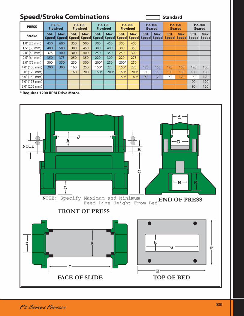
NOTE: Specify Maximum and Minimum Feed Line Height From Bed.
D K
IE
HFG
FACE OF SLIDE TOP OF BED
END OF PRESS
FRONT OF PRESS
P2-60 P2-100 P2-150 P2-200 P2-100 P2-150 P2-200 PRESS Flywheel Flywheel Flywheel Flywheel Geared Geared Geared
Std. Max. Std. Max. Std. Max. Std. Max. Std. Max. Std. Max. Std. Max. Stroke Speed Speed Speed Speed Speed Speed Speed Speed Speed Speed Speed Speed Speed Speed
1.0” (25 mm) 450 600 350 500 300 450 300 400 1.5” (38 mm) 400 500 300 450 300 400 300 350 2.0” (50 mm) 375 400 300 400 250 350 250 300 2.5” (64 mm) 350 375 250 350 220 300 220 275 3.0” (75 mm) 300 350 250 300 200* 250 200* 250 4.0” (100 mm) 200 300 160 250 150* 225 150* 225 120 150 120 150 120 150 5.0” (125 mm) 160 200 150* 200* 150* 200* 100 150 100 150 100 150 6.0” (150 mm) 150* 180* 90 120 90 120 90 120 7.0” (175 mm) 90 120 8.0” (205 mm) 90 120
Speed/Stroke Combinations Standard
* Requires 1200 RPM Drive Motor.

500PP415
240 WEST FIFTH STREET • MINSTER, OHIO 45865-0120 U.S.A. • PHONE: (419) 628-2331 • FAX: 419-628-3517
www.minster.com
Minster Has Sales and Service Offices Located Throughout the WorldContact Minster Direct For The Name of Your Global Representative
A Century of Heritage Pressed Into a Lifetime of Quality
Nidec Shimpo, Kyoto, JapanTelephone: +81-75-958-3606
Nidec Minster S. de R. L.Querétaro, MexicoTelephone: (52) 442-253-1671
Minster China, Ningbo, ChinaTelephone: +86 574 8630-8020
MINSTER®
A Group Company
Before You Invest in New Material Forming Technology, You're Invited toVisit Our Manufacturing, Training, Research, Parts and Service Facilities toSee How “Minster Quality” is Built Into All of Our Products and Services.
Minster GmbH,Halblech, Germany, Telephone: (49) 8368 9134 0
Nidec Minster, Minster,OH, Telephone: +1(419) 628-2331