a greenhouse gas accounting framework for carbon …
TRANSCRIPT
CEN
TER FOR C
LIMATE A
ND
ENERG
Y SOLU
TION
S
TEChNOLOGY
A GREENhOUSE GAS ACCOUNTING FRAMEWORk FOR CARBON CAPTURE AND STORAGE PROjECTS
by
Mike MccorMickcenter for climate and energy Solutionsformerly the Pew Center on Global Climate Change
February 2012
A G
REEN
hO
USE G
AS A
CC
OU
NTIN
G FR
AM
EWO
Rk
FOR
CA
RB
ON
CA
PTUR
E AN
D STO
RA
GE PR
OjEC
TS
by
Mike McCormick
Center For Climate and Energy Solutions
A Greenhouse GAs ACCountinG FrAMework For CArbon CApture And storAGe projeCts

Center for Climate and energy solutionsii

A Greenhouse Gas Accounting Framework for Carbon Capture and storage projects iii
Contents
Foreword v
aCknowledgements vi
exeCutive summary vii
introduCtion 1
1. Goals and objectives 1
2. document organization 1
3. scope and Applicability 2
4. overview of the GhG reduction Calculation Approach 3
5. overview of project Monitoring 3
6. principles of GhG reporting and Criteria for project Accounting 4
QuantiFying gHg emissions reduCtions 7
7. baselines 7
7.1 Baseline Options for CCS Projects 7
7.2 Baseline Considerations for Retrofit and New-Build CCS Projects 7
8. GhG Assessment boundaries 8
9. GHG Emissions Quantification Methodology 8
9.1 Calculation Procedure for Baseline Emissions 9
9.1.1 Calculation Procedure for Projection-Based Baseline 10
9.1.2 Calculation Procedure for Standards-Based Baseline 11
9.2 Calculation Procedure for Project Emissions 12
9.2.1 Calculation Procedures for CO2 Capture 12
9.2.2 Calculation Procedures for CO2 Transport 17
9.2.3 Calculation Procedures for CO2 Storage in Non-Producing Formations 20
9.2.4 Calculation Procedures for CO2 Storage in Producing Formations 23
9.2.5 Accounting for CO2 Leakage from Geologic Storage Formations to the Atmosphere 30
CCs ProjeCt monitoring 33
10. Monitoring plans 33
11. Monitoring parameters to Quantify GhG reductions 35
12. Monitoring Geologic storage of Co2 43
12.1 Overview of CO2 Storage Monitoring 43
12.2 CO2 Storage Monitoring Best-Practice Manuals and Guidance Documents 44

Center for Climate and energy solutionsiv
aPPendiCes 47
Appendix A: Additional GhG Accounting-related issues for CCs projects 47
Appendix b: the u.s. epA’s underground injection Control and Greenhouse Gas reporting programs 52
Appendix C: summary tables for baseline and project emissions Calculations 54
Appendix D: Supplemental Quantification Methods 63
endnotes 69
reFerenCes 73

A Greenhouse Gas Accounting Framework for Carbon Capture and storage projects v
Foreword eileen Claussen, president, Center for Climate and energy solutions
Meeting the global challenge to reduce greenhouse gas (GHG) emissions and avoid dangerous climate impacts requires deploying a portfolio of emission reduction technologies.
We must both commit to broad and deep efficiencies in the way our societies’ consume energy and to significant increases in power supplies from low carbon energy sources. At the same time, it is important to recognize that the scale of the challenge to reduce global emissions is massive, and that it will take decades for new and advanced low and zero emissions technologies to sufficiently mature and dominate the world’s primary energy supply.
Recognizing that the use of fossil fuels—including coal—will continue to maintain a central role in powering the global economy for at least the next several decades, the portfolio of solutions to achieve the necessary GHG emissions reductions must include carbon capture and storage (CCS). Geologic storage of carbon dioxide (CO2) emissions currently represents the only option to substantially address the GHG emissions from fossil fuel-fired power plants and large industrial facilities.
Our CCS Accounting Framework provides quantification methodologies to document the emissions reductions from CCS projects according to international best practices. It is intended to help project developers and program administrators identify and develop policies to recognize and reward investments that prevent CO2 from entering the atmosphere by capturing and safely and permanently storing it in deep geologic reservoirs.

Center for Climate and energy solutionsvi
aCknowledgementsTo inform all aspects of the CCS Accounting Framework, the Center on Climate and Energy Solutions (C2ES), formerly the Pew Center on Global Climate Change, formed a workgroup of North American experts. We are extremely grateful for the valuable contribution they provided during the document development process. Workgroup members advised on the overall scope of the work, provided insightful comments and feedback in their areas of expertise, reviewed drafts and helped ensure the accuracy of the methodologies proposed. All errors, omissions, characterizations, and recommendations are those of C2ES and should not be attributed to workgroup participants. Additionally, we are thankful for the project funding support provided by the North American Carbon Capture and Storage Association.
workgrouP PartiCiPants
Vello kuuskraa, Advanced resources international
ellen o’Connell, Air products
robert hilton, Alstom
emily rodgers, Anadarko
neeraj Gupta, battelle
jamie Callendar, blue source Canada
Mahesh Gundappa, blue strategies
susan hovorka, bureau of economic Geology, the university of texas at Austin
ed rubin, Carnegie Mellon university
steve jenkins, Ch2M hiLL
john Cain, Chevron
bruce hill, Clean Air task Force
derik broekhoff, Climate Action reserve
workgrouP observers
rajinder sahota, California Air resources board
elizabeth scheele, California Air resources board
jorg Aarnes, dnV energy
emily Fisher, edison electric institute
karen obenshain, edison electric institute
tim o’Connor, environmental defense Fund
richard rhudy, electric power research institute
Mike hirl, the hirl Group
Mike Moore, nACCsA
George peridas, nrdC
ken walsh, sAiC
dwight peters, schlumberger
sally benson, stanford university
john kadyszewski, winrock international
Mark deFegueiredo, epA
john Litynski, national energy technology Laboratory
A Greenhouse Gas Accounting Framework for Carbon Capture and storage projects vii
exeCutive summary The Greenhouse Gas Accounting Framework for Carbon Capture and Storage (CCS) Projects—CCS Accounting Framework—provides methods to calculate emissions reductions associated with capturing, transporting, and safely and permanently storing anthropogenic carbon dioxide (CO2) in geologic formations. It aims for consistency with the principles and procedures from ISO 14064-2:2006. Greenhouse gases—Part 2: Specification with guidance at the project level for quantification, monitoring and reporting of greenhouse gas emission reductions or removal enhancements, which represents best practice guidance for the quantification of project-based GHG emission reductions.
Ultimately, the objective of the CCS Accounting Framework is to inform and facilitate the develop - ment of a common platform to account for greenhouse gas (GHG) emissions reductions due to capturing and geologically storing CO2. It also contributes to the public discussion about the viability of CCS to serve as a feasible CO2 mitigation solution.
CCS refers to a suite of technologies that, when effectively combined, prevent CO2 from entering the atmosphere. The process involves capturing and compressing CO2 from power plants and other industrial facilities, transporting it to suitable storage sites, and injecting it into geologic formations for secure and permanent sequestration.
The emissions accounting procedures in the CCS Accounting Framework apply to multiple CO2 source types, including electric power plants—equipped with pre-combustion, postcombustion, or oxy-fired technologies—and industrial facilities (for example, natural gas production, fertilizer manufacturing, and ethanol production). For CO2 transport, the calculation methodology in this document applies only to pipelines because while other methods of transport, (e.g., truck transport) are possible, they are typically not considered viable options for large-scale CCS endeavors. With respect to the geological storage of CO2, the CCS Accounting Framework applies to saline aquifers, depleted oil and gas fields, and enhanced oil and gas recovery sites.
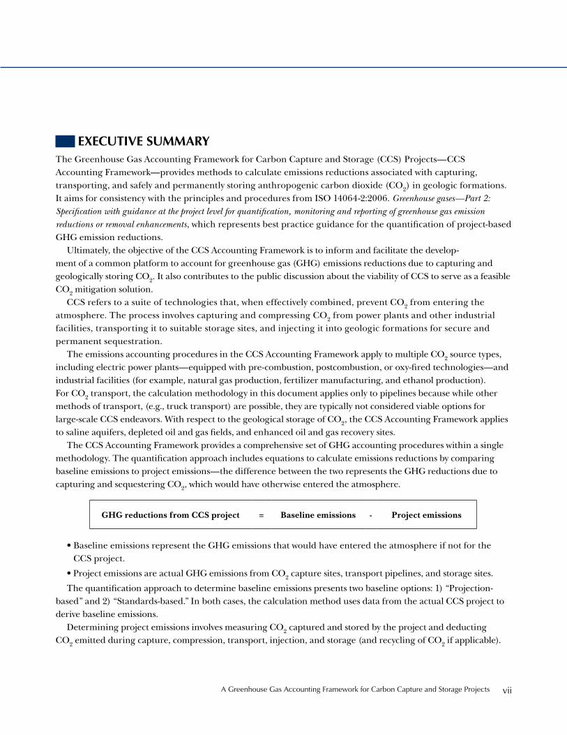
The CCS Accounting Framework provides a comprehensive set of GHG accounting procedures within a single methodology. The quantification approach includes equations to calculate emissions reductions by comparing baseline emissions to project emissions—the difference between the two represents the GHG reductions due to capturing and sequestering CO2, which would have otherwise entered the atmosphere.
• Baseline emissions represent the GHG emissions that would have entered the atmosphere if not for the CCS project.
• Project emissions are actual GHG emissions from CO2 capture sites, transport pipelines, and storage sites.
The quantification approach to determine baseline emissions presents two baseline options: 1) “Projection-based” and 2) “Standards-based.” In both cases, the calculation method uses data from the actual CCS project to derive baseline emissions.
Determining project emissions involves measuring CO2 captured and stored by the project and deducting CO2 emitted during capture, compression, transport, injection, and storage (and recycling of CO2 if applicable).
GHG reductions from CCS project = Baseline emissions - Project emissions

Center for Climate and energy solutionsviii
The procedure to determine project emissions also accounts for GHG emissions from energy inputs required to operate CO2 capture, compression, transport, injection and storage equipment. Energy inputs include “direct emissions” from fossil fuel use (Scope 1 emissions) and, in case required by a program authority, “indirect emis-sions” from purchased and consumed electricity, steam, and heat (Scope 2 emissions).
CCS project monitoring covers large above ground industrial complexes and expansive subterranean geologic formations. In terms of emissions accounting, monitoring CO2 capture and transport involves well known tech-nologies and practices, established over many years for compliance with federal and state permitting programs. Therefore, the monitoring program would follow generally accepted methods and should correspond with GHG monitoring requirements associated with the relevant subparts of EPA’s Greenhouse Gas Reporting Program (GHGRP) and other state-level programs.
On the other hand, monitoring geologic storage sites for the purpose of verifying the safe and permanent sequestration CO2 from the atmosphere is a relatively recent activity that may involve new techniques and tech-nologies. While there exists no standard method or generally accepted approach to monitor CO2 storage in deep rock formations, project developers will benefit from monitoring practices deployed over the past 35 years in CO2 enhanced oil and gas recovery operations. Thus, the CCS Accounting Framework does not prescribe an approach to monitor CO2 sequestration, as geologic storage sites will vary from site to site and demand unique, fit-for-purpose monitoring plans. This approach is consistent with the monitoring, reporting and verification (MRV) procedures for geologic sequestration from subpart RR to EPA’s Greenhouse Gas Reporting Program, which overlays the monitoring requirements associated with the Underground Injection Control Program.

A Greenhouse Gas Accounting Framework for Carbon Capture and storage projects 1
introduCtionThe Greenhouse Gas (GHG) Accounting Framework for Carbon Capture and Storage (CCS) Projects—CCS Accounting Framework—provides methods to calculate emissions reductions associated with capturing, trans-porting, and safely and permanently storing carbon dioxide (CO2) in geologic formations. It also includes options for defining baselines, delineating project assess-ment boundaries, and monitoring project performance.
CCS refers to a suite of technologies that, when effec-tively combined, prevents CO2 from entering the atmo-sphere. The process involves capturing and compressing CO2 from power plants and other industrial facilities, transporting it to suitable storage sites, and injecting it into appropriate geologic formations for secure and permanent sequestration.
1. goals and objeCtives
Ultimately, the objective of the CCS Accounting Framework is to inform and facilitate the development of a common platform to account for CO2 emissions reductions associ-ated with capturing and geologically storing CO2.
The methods to determine baselines, delineate boundaries, quantify emissions, and monitor project performance represent a first-attempt to provide an inte-grated emissions accounting methodology for a range of CCS projects types, consistent with the International Standards Organization’s (ISO) GHG accounting stan-dard, 14064-2:2006: Specification with guidance at the project level for quantification, monitoring and reporting of greenhouse gas emission reductions or removal enhancements.
By presenting approaches to calculate the emissions reductions from CCS projects according to commonly accepted GHG accounting principles and criteria (see Section 6), the CCS Accounting Framework aims to contribute to the public discussion about the viability of CCS to serve as a feasible CO2 mitigation solution. This document could also assist regulators evaluate options to incorporate CCS into energy and climate-related programs within their jurisdiction. Furthermore, it could inform assessments by CCS project developers and inves-tors of project development risks and opportunities.
box 1: Policy-neutral gHg accounting guidance
the CCs Accounting Framework does not recommend specific policy mechanisms to reward or incentivize CCs. this document is intentionally designed to be “policy neutral”—i.e., to be useful for multiple types of policy options. therefore, the methodology could assist with the quantification of emissions reductions for tax credits, bonus allowances in a cap and tradetype of program, offsets credits (for compliance or voluntary commitments), or other potential mechanisms.
GhG programs that use the emissions accounting methods in this document will need to provide additional information on program-specific rules that compliment the technical guidance to calculate emissions reductions. For example, program authori-ties would augment the GHG quantification proce-dures with rules on long-term liability for reversals of emissions reductions, ownership of emissions reductions, “additionality” criteria, Co2 storage standards for “permanence,” and determination of baselines, among other matters. Appendix A provides a discussion of additional policy-related issues that policymakers may need to address, depending on the nature of the program or policy.
2. doCument organization
The CCS Accounting Framework is organized into three parts:
• The first part (sections one through six) provides an overview of the CCS Accounting Framework’s goals and objectives, scope and applicability, the emissions reduction and project monitoring approaches, and discusses how this document relates to commonly accepted GHG accounting principles and project criteria.
Center for Climate and energy solutions2
• Sections seven through nine in the second part present options for selecting baselines, consider-ations for delineating boundaries to conduct a GHG assessment, and methods to quantify GHG emissions reductions from CCS projects through a series of calculation procedures.
• The last part of the document (sections ten through twelve) includes project monitoring guidance to collect and organize data to quantify GHG reduc-tions from CCS projects; it also provides references for monitoring effective containment of injected CO2 in geologic reservoirs.
Appendix A discusses four policy-related issues that could impact rules and procedures to quantify the GHG reductions from CCS projects. Appendix B provides an overview of the U.S. Environmental Protection Agency’s (EPA) Underground Injection Control Program and Greenhouse Gas Reporting Program. Appendix C includes summary tables of baseline and project calcu-lation methods. Appendix D includes supplemental emissions quantification methods.
3. sCoPe and aPPliCability
The scope of the CCS Accounting Framework includes CO2 capture, as well as pipeline transport and CO2 injection and geologic storage. Correspondingly, it provides methods to quantify GHG emissions from the anthropogenic source of CO2 to the underground CO2 storage reservoir.
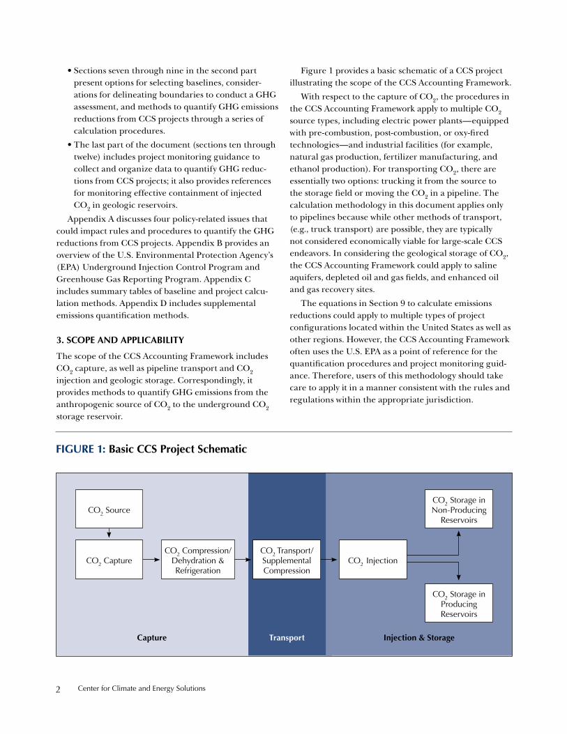
Figure 1 provides a basic schematic of a CCS project illustrating the scope of the CCS Accounting Framework.
With respect to the capture of CO2, the procedures in the CCS Accounting Framework apply to multiple CO2 source types, including electric power plants—equipped with pre-combustion, post-combustion, or oxy-fired technologies—and industrial facilities (for example, natural gas production, fertilizer manufacturing, and ethanol production). For transporting CO2, there are essentially two options: trucking it from the source to the storage field or moving the CO2 in a pipeline. The calculation methodology in this document applies only to pipelines because while other methods of transport, (e.g., truck transport) are possible, they are typically not considered economically viable for large-scale CCS endeavors. In considering the geological storage of CO2, the CCS Accounting Framework could apply to saline aquifers, depleted oil and gas fields, and enhanced oil and gas recovery sites.
The equations in Section 9 to calculate emissions reductions could apply to multiple types of project configurations located within the United States as well as other regions. However, the CCS Accounting Framework often uses the U.S. EPA as a point of reference for the quantification procedures and project monitoring guid-ance. Therefore, users of this methodology should take care to apply it in a manner consistent with the rules and regulations within the appropriate jurisdiction.
Figure 1: basic CCs Project schematic
Co2 storage in non-producing
reservoirs
Co2 storage in producing reservoirs
Co2 injectionCo2 transport/ supplemental Compression
Co2 Compression/ dehydration & refrigeration
Co2 Capture
Co2 source
Capture transport injection & storage

A Greenhouse Gas Accounting Framework for Carbon Capture and storage projects 3
box 2: CCs Project developer and Program authority
Project developer. the term “project developer” is used throughout the document to generally represent the entity implementing the CCs project and electing to take responsibility to meet certain measurement and monitoring requirements. For ease of use, this document does not distinguish between the different entities involved in the multiple compo-nents of a CCs project—Co2 capture, transport, or storage site operators are collectively referred to as the “project developer.”
Program authority. the term “program authority” refers to an agency or authorized organization responsible for a state or federal GhG program or an organization that runs a voluntary GhG inven-tory or offset registry. if a program authority chooses to recognize and reward the Co2 reductions associ-ated with CCs projects, it could incorporate the approaches in the CCs Accounting Framework into its protocols and augment it with program-specific rules and requirements.
4. overview oF tHe gHg reduCtion CalCulation aPProaCH
The CCS Accounting Framework provides GHG accounting procedures for CCS projects. The quantifica-tion approach includes equations to calculate emissions reductions by comparing baseline emissions to project emissions—the difference between the two represents the GHG reductions due to capturing and sequestering CO2, which would have otherwise entered the atmo-sphere if not for the CCS project.
• Baseline emissions represent the GHG emissions that would have entered the atmosphere if not for the CCS project.
• Project emissions are actual emissions from CO2 capture sites, transport pipelines, and storage sites.
The emissions quantification approach to deter-mine baseline emissions is structured according to the following two options: 1) “Projection-based” and 2) “Standards-based.” In both cases, the calculation method uses data from the actual CCS project to derive baseline emissions.
Calculating project emissions involves measuring CO2 captured and stored by the project and deducting CO2 emitted during capture, compression, transport, injection, and storage (and recycling of CO2 if appli-cable). The procedure to determine project emissions also accounts for GHG emissions from energy inputs required to operate CO2 capture, compression, trans-port, injection and storage equipment. Energy inputs include “direct emissions” from fossil fuel use (Scope 1 emissions) and, in case required by a program authority, “indirect emissions” from purchased and consumed electricity, steam, and heat (Scope 2 emissions).1
5. overview oF ProjeCt monitoring
CCS project monitoring applies to large above ground industrial complexes and expansive subterranean geologic formations.
Monitoring CO2 capture and transport for emissions accounting purposes involves well known technologies and practices, established over many years for compli-ance with federal and state permitting programs. Therefore, the monitoring program would follow generally accepted methods and correspond with GHG monitoring requirements associated with the relevant subparts of EPA’s Greenhouse Gas Reporting Program (GHGRP)2 and other state-level programs, as necessary.
On the other hand, monitoring geologic storage sites to verify the safe and permanent sequestration of CO2 from the atmosphere is a relatively recent activity that could make use of existing technologies in new ways. Furthermore, there exists no standard method or generally accepted approach to monitor CO2 storage in subsurface formations, applicable to all types of CO2 storage operations. However, developing CO2 storage monitoring plans will benefit from monitoring practices deployed for over 35 years for CO2 enhanced oil and gas recovery, as well as waste management operations that involve injections into the subsurface.
Since the primary objective of this document is to present emissions accounting approaches, the project monitoring guidance in Section 11 includes methods to collect data to execute equations to determine baseline
GHG reductions from CCS project = Baseline
emissions - Project emissions
Center for Climate and energy solutions4
emissions and project emissions, in correspondence with the GHG quantification procedures in Section 9.
Thus, with respect to monitoring geologic storage reservoirs to confirm that injected CO2 remains seques-tered from the atmosphere, Section 12 provides a list of resources on CO2 storage monitoring technologies and techniques to inform project developers’ choices about deploying systems across project phases. This approach reflects the reality that unique, site-specific conditions for each reservoir preclude the development of prescriptive monitoring guidance. Rather than impose a one-size-fits-all monitoring regime for CO2 storage sites, the CCS Accounting Framework directs project developers to use best practices to design a site-specific CO2 storage monitoring plan, which would be incorporated into an overall monitoring plan for the CCS project. The development of reservoir-specific monitoring plans, in which project developers create strategies to detect and quantify leakage of CO2 out of the geologic storage complex to the atmosphere, is included in the MRV procedures for geologic sequestration from subpart RR to EPA’s GHGRP, which overlays the monitoring requirements associated with the Underground Injection Control (UIC) Program.3 Appendix B provides a description of the EPA’s UIC program and GHGRP.
6. PrinCiPles oF gHg rePorting and Criteria For ProjeCt aCCounting
As stated above, the CCS Accounting Framework aims for consistency with the principles and procedures from ISO 14064-2, which represents best practice guidance for the quantification of project-based GHG emission reductions.4
The emissions quantification procedures reflect generally accepted accounting and reporting principles and criteria, such that reported information should represent a faithful, true, and fair assessment of the impact of the CCS project. The following principles serve as the foundation for identifying GHG sources and sinks and quantifying emissions. The CCS Accounting Framework is designed to satisfy these principles to help assure the credibility of calculated GHG reductions.
• Relevance—Select GHG sources, sinks, reservoirs, data and methodologies appropriate to the scope of the project and needs of the intended user.
• Completeness—Include all relevant GHG emissions, removals, and storage.
• Consistency—Enable meaningful comparisons of GHG-related information.
• Accuracy—Reduce bias and uncertainties as far as practical.
• Transparency—Disclose sufficient and appropriate GHG-related information to allow intended users to make decisions with reasonable confidence.
• Conservatism—Where questions arise regarding uncertain parameters or data sources, or where further analysis is not cost-effective, choose a conservative approach that is likely to underestimate rather than overestimate GHG reductions.
In addition to the overarching principles applicable to all GHG accounting and reporting activities, projects that quantify emissions reductions must also meet defined GHG project criteria. Specifically, projects wishing to quantify emission reductions may have an obligation to satisfy certain project accounting criteria to substantiate the veracity of their GHG reduction claims. For example, California’s Global Warming Solutions Act of 2006, Assembly Bill 32 (AB32–Núñez, Chapter 488, Statutes of 2006) states that the California Air Resources Board (the regulatory agency responsible for implementing AB32) should only approve GHG reduction projects that are quantifiable, additional, permanent, verifiable, and enforceable.5 Table 1 describes these criteria.
box 3: data access
The quantification methods and monitoring param-eters described in the CCs Accounting Framework presume CCs project developers have full access to data. however, in most cases, a single entity will not own and operate the Co2 capture, transport, and storage equipment and sites. As such, propri-etary information challenges may exist. when these challenges arise, cooperation among the different entities that own and/or operate the capture, trans-port and storage components will be required. table 2 in section 11 provides data collection informa-tion on the variables to monitor—i.e., “monitoring parameters”—for project developers to carry out the emissions quantification equations.

A Greenhouse Gas Accounting Framework for Carbon Capture and storage projects 5
table 1: gHg Project accounting Criteria
Criterion deFinition
Real/Quantifiable reductions represent an actual, measurable/calculable decrease in GhG emissions due to the project, which would have otherwise entered the atmosphere.
see section 9 for a presentation of calculation procedures to quantify GhG reductions from CCs projects.
Additional reductions represent a decrease in GhG emissions incremental to what would have happened if not for the project—i.e., beyond business as usual.
Appendix A provides a discussion of additionality.
Permanent GhG reductions from the project are not reversible—i.e., Co2 remains sequestered at a level and duration that achieves a clear atmospheric benefit, as defined by a program authority.
Appendix A provides a discussion about permanence and reversals in GhG reductions.
Verifiable Confirmation that the GHG reductions from the project are consistent with the methodologies provided by the appropriate program authority.
Enforceable Identification of clear roles and responsibilities among project participants and between project participants and a program authority to hold responsible parties accountable for not meeting commitments to program authorities.
see Appendix A for a discussion about ownership of emissions reductions.

Center for Climate and energy solutions6

A Greenhouse Gas Accounting Framework for Carbon Capture and storage projects 7
QuantiFying gHg emissions reduCtions
The purpose of the following sections is to present GHG calculation methods to quantify emissions reductions from CCS projects. The quantification approach involves comparing derived baseline emissions to actual project emissions. The difference between the two represents the emission reductions from the CCS project.
Section 7 provides information on identifying and selecting a baseline (against which to compare actual emissions from the project). Section 8 illustrates bound-aries for the quantification exercise. Section 9 presents methods to calculate baseline and project emissions within the quantification boundary.
7. baselines
In terms of GHG project accounting, a baseline is a hypothetical situation that represents the condition most likely to occur in the absence of the GHG emission reduc-tion project. It serves as a reference case against which to quantitatively compare the GHG emissions associated with the project and derive net emission reductions.6
The CCS Accounting Framework presents two baseline options, referred to as “Projection-based” and “Standards-based.”
7.1. Baseline Options for CCS Projects
A project developer would select the baseline that applies to its project, and then follow the matching calculation procedure. The choice of baseline dictates the equations applied, as provided in Section 9.1.1 and 9.1.2:
Projection-based baseline à Equation 2
Standards-based baseline à Equation 3
Projection-based. This option represents a baseline that would correspond with the project’s actual CO2 capture site, absent the capture and compression system located at the CO2 source. For example, if the CCS project includes a coal electricity generator with post-combustion capture, a Projection-based baseline would be the coal plant without
CO2 capture; similarly, if the CCS project captures CO2 from acid-gas removal associated with natural gas produc-tion, a Projection-based baseline would be the natural gas production facility with acid gas removal but with CO2 vented to the atmosphere.
According to the calculation approach, project developers determine Projection-based baseline emissions according to actual measured quantities of CO2 captured from the project, which would have been vented to the atmosphere had the CCS project not been implemented, minus the incremental CO2 generated at the capture site due to CO2 capture equipment. The calculation uses data collected from the CO2 capture site to represent the quantity of emissions prevented from entering the atmosphere.
Standards-based. The Standards-based baseline is expressed in the form of a metric or “performance stan-dard” (tCO2e/unit of output). Depending on the circum-stance, it could correspond with a similar or different technology than the CCS project’s actual CO2 capture site, but which fulfills the same purpose and function. For instance, if the CCS project includes a coal electricity generator with post-combustion capture, a Standards-based baseline could be represented by a coal-fired or natural gas-fired power plant’s emissions rate, expressed as tons CO2/MWh. In this case, baseline emissions would be calculated by multiplying the actual MWhs delivered to the grid in the project condition (net MWh) times the emissions rate approved by the program authority.
A Standards-based baseline is sector specific, at minimum, to ensure reasonable accuracy, and it could have a different emissions profile than the technology used at the CO2 capture site.
7.2. Baseline Considerations for Retrofit and New-Build CCS Projects
Depending on the situation, either the Projection-based or Standards-based baseline could apply to projects that

Center for Climate and energy solutions8
capture CO2 at power generation or other industrial facilities, and inject CO2 at various types of storage sites.
Retrofit CCS Projects. Given the limited number of climate change policies that require GHG emissions reductions from facilities in the U.S., the baseline for most retrofit projects would involve the continued operation of the existing CO2 source facility, but without carbon capture and storage—such that produced CO2 is vented to the atmosphere. This corresponds with the Projection-based baseline.
However, if the retrofit involves a major overhaul of technologies, then applying a Projection-based baseline might not be the most reasonable approach. Instead, it may be more appropriate to characterize the baseline in terms of the emissions rate associated with a specific technology, often called a performance standard.
A Standards-based baseline could also apply to retrofit projects if a law or regulation affects CO2 emissions production at the capture site, such as a mandate to meet a minimum GHG emission performance standard.
New Build CCS Projects. The baseline for new facilities will often correspond with the common practice in the region and the most economic option available to the project developer. As with retrofit projects, provided that there are no regulations in place that require the use of certain technologies, mandate the installation of CCS, or prevent the implementation of the most common technology option, the baseline for a new build facility would likely be the operation of the project configura-tion without the CCS capture component that vents all of the produced CO2 to the atmosphere—a Projection-based baseline.
However, multiple economic and market, social, envi-ronmental, and political considerations exist that impact technology choices and configurations. Thus, project developers could decide that an emissions performance standard best represents its project circumstances—as opposed to as a “continuation of current practices”—and program authorities could similarly decide that a Standards-based baseline is most suitable for its program.
8. gHg assessment boundaries
The GHG assessment boundary defines the scope of the emissions quantification methodology. It demarcates the sources included in the project and baseline emissions calculation (as presented in Section 9).
Recognizing the variety and complexity of project configurations where CO2 may be captured and
compressed, transported and injected into different types of reservoirs, Figure 2 provides a general illustra-tion of project boundaries to account for the full range of potential CCS project types.
Leakage. An important consideration when determining the project boundary is “leakage,” which refers to unintended increases in emissions due to the project activity—usually occurring outside the physical project boundary. An objective in defining boundaries is to minimize or avoid leakage.
In this CCS Accounting Framework, the project boundary is intentionally drawn broadly to avoid unac-counted emissions associated with capturing and storing CO2. Specifically it covers the full CCS value chain, including emissions from CO2 recovery and re-injection operations at enhanced oil and gas recovery sites.
Program authorities will ultimately decide the scope of the GHG assessment boundary and the extent to which it includes emission sources upstream of the CO2 capture site and downstream of CO2 storage.
Primary Process. The installation of CO2 capture may impact one or more emissions sources at a facility, but may also leave unaffected other sources. Therefore, to ensure the emissions reduction calculation approach reflects the relevant change in emissions due to the project, the baseline and project boundaries should focus on incorporating GHG sources affected by the project—i.e., the change in emissions due to capturing CO2. For example, a boundary for CO2 capture at a hydrogen production unit within a refinery would encompass systems associated with the hydrogen production process but might exclude downstream units that use the hydrogen (e.g., hydro-treating units) or other upstream processes unaffected by the CO2 capture system.
The specific power generation or industrial process (e.g., natural gas processing, hydrogen production, steelmaking) creating the captured CO2 is referred to in this document as the “primary process.” If CO2 is captured from more than one process, then project developers should combine them within the boundary that encompasses the capture site.
9. gHg emissions QuantiFiCation metHodology
Overall GHG emission reductions from the CCS project equal Baseline Emissions (BE) minus Project Emissions (PE), as shown in Equation 1. The calculation procedures

A Greenhouse Gas Accounting Framework for Carbon Capture and storage projects 9
for the baseline emissions and project emissions are presented in the following sections.7
9.1. Calculation Procedure for Baseline Emissions
The CCS Accounting Framework provides two approaches to calculate baseline CO2 emissions—Projection-based and Standards-based. To be conserva-tive, the procedures do not calculate methane (CH4) or nitrous oxide (N2O) emissions.
Figure 2: CCs Project boundary
Capture transport injection & storage
Co2 Fugitive (subsurface reservoir)
Co2 Fugitive (equipment)
Co2, Ch4, n2o stationary
combustion (if applicable)
Co2, Ch4, n2o stationary
combustion
Co2, Ch4, n2o stationary
combustion
Co2, Ch4, n2o stationary
combustion
Co2 Venting Co2 Venting Co2 Venting
Co2 Venting
Co2 not captured
Co2 Fugitive Co2 Fugitive Co2 Fugitive
Co2 source: power Generation or
industrial Facility
keyFlow of Co2
emission
Co2 Capture & Compression/ dehydration &
refrigeration system
Co2 transport and supplemental Compression
Co2 injection
producing reservoirs
non-producing reservoirs
Co2 storage
eQuation 1: total annual gHg reductions
GHG Reductions y = BE y - PE yWhere,
GHG Reductions y = Total annual GHG reductions from the CCS project (tCO2e/yr).
BE y = Baseline CO2e Emissions in each year (tCO2e/yr).
PE y = Project CO2e Emissions in each year (tCO2e/yr).
Functional Equivalence. The implementation of CO2 capture infrastructure may result in changes to energy consumption and/or product output, and impact the quan-tity of GHG emissions produced at the capture site. Since the calculation of baseline emissions involves collecting and using actual project data from the capture site, a project developer could inaccurately quantify emissions reductions from the CCS project if it does not appro-priately maintain “functional equivalence” between the baseline and project and adjust applied data, as necessary.

Center for Climate and energy solutions10
For example, in some project configurations, incre-mental emissions associated with running the capture system could yield an overall increase in CO2 production and result in a larger volume of CO2 captured and processed, relative to what the “primary process” would have emitted in the baseline. A power plant retrofitted with post-combustion CO2 capture, for instance, that maintains (net) electricity production levels by burning additional coal to produce steam and electricity to power the capture system would increase overall CO2 produc-tion. In this case, using actual measured CO2 production values from the project to derive baseline emissions could overestimate baseline emissions.
Alternatively, a similar power plant could burn an equivalent amount of coal as the pre-retrofit plant and correspondingly produce the same amount of CO2 as the baseline. This might occur if steam from the coal-fired boiler is directed toward the capture system to regenerate the CO2 absorber rather than the power cycle. Therefore, while the capture system would not cause an increase in total CO2 production, it could lead to the generation of less electricity. In this case, if a project developer uses actual electricity production data to derive baseline emissions, it could underestimate baseline emissions.
In other project configurations, some or all of the incremental energy needed to meet the demands of
the CO2 capture system could be provided through separately powered systems, including process heaters, boilers, engines, turbines or other fossil fuel-fired equip-ment. In this case, the corresponding CO2 emissions streams would likely be separate from the captured CO2 from the primary process.
Project developers should adjust actual project data relied upon to quantify baseline emissions, if necessary. This is done to ensure that the quantified emissions reductions appropriately represent the impact of the CCS project and that the comparison between project and baseline emissions maintains “functional equivalence.”
9.1.1. Calculation Procedure for Projection-Based Baseline
The Projection-based baseline uses actual GHG emis-sions from the project to represent what would have occurred in the absence of CCS.
The procedure involves multiplying the amount of actual CO2 produced by the primary process, (which project developers measure immediately downstream of the primary process) by an “adjustment factor” that accounts for incremental changes in CO2 produced by the capture equipment and included in the measured CO2 stream. As discussed above, the adjustment factor is a part of the equation to maintain functional equiva-lence between the baseline and project. As approved by a
eQuation 2: total annual Projection-based baseline gHg emissions
be Projection-based, y = (vol. gas Produced, y x %Co2 x rCo2) x aF
where,
be Projection-based, y = Baseline emissions for a CCS project where the baseline scenario is defined using a Projection-based approach in each year (tCo2/yr).
vol. gas Produced, y = Volume of actual Co2 gas produced from the primary process, metered at a point immediately downstream of the primary process, at standard conditions, in each year (m3 gas/yr).
%Co2 = % Co2 in the gas stream, monitored immediately downstream of the primary process, in each year (% volume).
rCo2 = density of Co2 at standard conditions (metric ton/m3).
aF = baseline “adjustment factor” to account for incremental Co2 from the capture equipment and included in the measured Co2 stream (unitless).8 determined on a project-by-project basis.
if the Co2 capture system is separately run and operated and the corresponding Co2 emissions are not included in the “Vol. Gas produced, y Co2” term, then insert 1 (one) for this term.

A Greenhouse Gas Accounting Framework for Carbon Capture and storage projects 11
program authority, project developers would determine the appropriate way to correct measured CO2 emissions on a project-by-project basis.
As provided in Equation 2, for combustion processes the mass of CO2 could be determined from flue gas volume and composition measurements. Table 2 in Section 11 includes the monitoring parameters.
9.1.2 Calculation Procedure for Standards-based Baseline
The Standards-based baseline is calculated by multi-plying an emissions intensity metric or “performance standard,” expressed as (tCO2e/unit of output), by the actual output of the project’s primary process (e.g., MWh for power generation, MMscf processed for natural gas production), as provided in Equation 3.
Program authorities will ultimately approve the level of CO2 production for the numerator of the metric, based on the type of facility creating the captured CO2,
and, for the denominator, define the “output” of the primary process to maintain functional equivalence between baseline emissions and project emissions. Procedures for collecting data from the actual project to determine the “output” value used to calculate baseline emissions should be set to ensure that the quantified emissions reductions appropriately represents the impact of the CCS project.
For example, regarding CCS projects that involve power generation, electricity may be used to operate the CO2 compressors or other equipment associated with the capture system—reducing the amount of electricity delivered to the grid or sold to direct connected users, as compared to a facility without CO2 capture. In this case, using gross electricity production as the “output” might be more appropriate then net electricity production.
Table 2 in Section 11 provides the monitoring param-eters for the Standards-based baseline calculation.
eQuation 3: total annual standards-based baseline emissions
be standards-based = be performance standard * output ywhere,
be standards-based = standards-based baseline emissions for a CCs project in year y (tCo2/yr).
be performance standard = Baseline emissions intensity metric, specific to the type of primary process that creates the CO2 for capture, as prescribed by the relevant program authority (tCo2e/unit of output).
output y = units of output from the Co2 capture facility (e.g., Mwh) in the project condition in year y (units of output).
eQuation 4: total Project emissions
Pe y = Pe Capture, y + Pe transport, y + Pe storage-nP, y + Pe storage-P, y
where,
Pe y = project emissions from CCs project in year y (tCo2e/yr).
Pe Capture, y = project emissions from Co2 capture and compression in year y (tCo2e/yr). refer to section 9.2.1.
Pe transport, y = project emissions from Co2 transport in year y (tCo2e/yr). refer to section 9.2.2.
Pe storage-nP, y = project emissions from Co2 injection and storage in non-producing formations in year y (tCo2e/yr). refer to section 9.2.3 and 9.2.5.
Pe storage-P, y = project emissions from Co2 injection and storage in producing formations in year y (tCo2e/yr). refer to sections 9.2.4 and 9.2.5.

Center for Climate and energy solutions12
9.2 Calculation Procedure for Project Emissions
CCS project emissions equal the sum of CO2e emissions from CO2 capture, transport, and storage in producing or non-producing formations, as shown in Equation 4.9
9.2.1 Calculation Procedures for CO2 Capture
The calculation procedure for the CO2 capture process reflects the delineation of the boundary of the capture site, which encompasses the source of CO2, as well as auxiliary equipment associated with the CO2 capture and compression systems. In many cases, the primary process that generates the CO2 is part of a large industrial complex (e.g., a refinery, bitumen upgrader, chemical plant, gas processing plant, etc.) with many processes unaffected by or independent of the CO2 capture activities. As discussed above, only those processes directly impacted by the CO2 capture process are included in the quantification assess-ment. The boundary of the capture site extends to the point at which CO2 enters the pipeline, typically the point at which CO2 is transferred to the CO2 pipeline operator.
Equation 5 outlines the methods for calculating emissions from the capture segment of CCS projects. This equation is applicable to pre-combustion capture, post-combustion capture, oxy-fuel capture and CO2 capture at industrial sites.
Consistent with the objective to provide a complete assessment of the impact of the CCS project, this quanti-fication method accounts for all non-captured emissions from the primary process that enter the atmosphere. For example, a post-combustion system might capture 90
percent of CO2 created by a power production facility; thus, the ten percent not-captured is incorporated into the quantification approach to provide a comprehensive representation of the emissions profile of the capture segment of the CCS project.
The calculation approach collectively refers to CO2 from the primary process emitted to the atmosphere through vent stacks and fugitive releases from equip-ment at the capture and compression systems as “non-captured CO2.”
Vented and fugitive emissions from capturing and compressing CO2 include both intentional and uninten-tional releases. CO2 may be vented through dedicated vent stacks during normal operation, process upsets, or shutdowns. Fugitive emissions may arise from leakage of CO2 from equipment such as flanges, valves and flow meters.
Equations 5.1, 5.1.A, 5.1.B, and 5.1.C account for the portion of CO2 generated from the primary process that is not captured but emitted to the atmosphere. Project developers calculate emissions by subtracting CO2 transferred to the transport segment of the CCS project from total CO2, CH4, and N2O produced from the primary process. Table 2 in Section 11 provides the monitoring parameters to calculate total annual CO2 produced from the primary process and transferred to the CO2 pipeline; it also provides the monitoring parameters necessary for calculating the CH4 and N2O emissions from the primary process.
eQuation 5.0: total annual Project emissions from the Capture segment
Pe Capture, y = Pe C-PP, y + Pe C-Comb, y + Pe C-indirect energy, y
where,
Pe Capture, y = project emissions from Co2 capture and compression in each year (tCo2e/yr).
Pe PP, y = project emissions from the primary process (physical Co2 emissions) that have not been captured by the Co2 capture process, including project emissions from venting of Co2 during capture and compression, and project emissions from fugitive releases of Co2 during capture and compression in each year (tCo2/yr). refer to equation 5.1.
Pe Comb, y = project emissions from on-site use of fossil fuels to operate support equipment for the Co2 capture and compression facilities in each year (tCo2e/yr). refer to equation 5.2.
Pe indirect energy, y = project emissions from purchased electricity and thermal energy used to operate the Co2 capture and compression systems in each year (tCo2e/yr), if required by a program authority. refer to equation 5.3.
A Greenhouse Gas Accounting Framework for Carbon Capture and storage projects 13
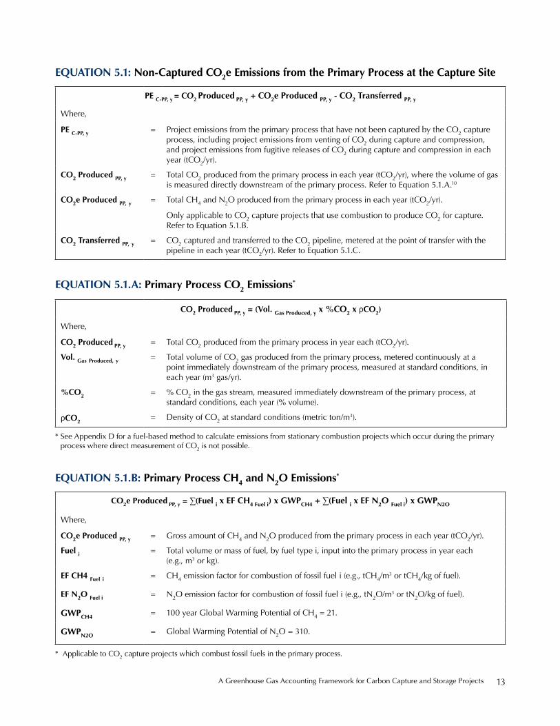
eQuation 5.1: non-Captured Co2e emissions from the Primary Process at the Capture site
Pe C-PP, y = Co2 Produced PP, y + Co2e Produced PP, y - Co2 transferred PP, y
where,
Pe C-PP, y = project emissions from the primary process that have not been captured by the Co2 capture process, including project emissions from venting of Co2 during capture and compression, and project emissions from fugitive releases of Co2 during capture and compression in each year (tCo2/yr).
Co2 Produced PP, y = total Co2 produced from the primary process in each year (tCo2/yr), where the volume of gas is measured directly downstream of the primary process. refer to equation 5.1.A.10
Co2e Produced PP, y = total Ch4 and n2o produced from the primary process in each year (tCo2/yr).
only applicable to Co2 capture projects that use combustion to produce Co2 for capture. refer to equation 5.1.b.
Co2 transferred PP, y = Co2 captured and transferred to the Co2 pipeline, metered at the point of transfer with the pipeline in each year (tCo2/yr). refer to equation 5.1.C.
eQuation 5.1.a: Primary Process Co2 emissions*
Co2 Produced PP, y = (vol. gas Produced, y x %Co2 x rCo2)
where,
Co2 Produced PP, y = total Co2 produced from the primary process in year each (tCo2/yr).
vol. gas Produced, y = total volume of Co2 gas produced from the primary process, metered continuously at a point immediately downstream of the primary process, measured at standard conditions, in each year (m3 gas/yr).
%Co2 = % Co2 in the gas stream, measured immediately downstream of the primary process, at standard conditions, each year (% volume).
rCo2 = density of Co2 at standard conditions (metric ton/m3).
eQuation 5.1.b: Primary Process CH4 and n2o emissions*
Co2e Produced PP, y = ∑(Fuel i x eF CH4 Fuel i) x gwPCH4 + ∑(Fuel i x eF n2o Fuel i) x gwPn2o
where,
Co2e Produced PP, y = Gross amount of Ch4 and n2o produced from the primary process in each year (tCo2/yr).
Fuel i = total volume or mass of fuel, by fuel type i, input into the primary process in year each (e.g., m3 or kg).
eF CH4 Fuel i = Ch4 emission factor for combustion of fossil fuel i (e.g., tCh4/m3 or tCh4/kg of fuel).
eF n2o Fuel i = n2o emission factor for combustion of fossil fuel i (e.g., tn2o/m3 or tn2o/kg of fuel).
gwPCH4 = 100 year Global warming potential of Ch4 = 21.
gwPn2o = Global warming potential of n2o = 310.
* see Appendix d for a fuel-based method to calculate emissions from stationary combustion projects which occur during the primary process where direct measurement of Co2 is not possible.
* Applicable to Co2 capture projects which combust fossil fuels in the primary process.

Center for Climate and energy solutions14
Emissions quantification at the CO2 capture site also includes stationary combustion and electric-drive units to support the capture and compression processes, such as cogeneration units, boilers, heaters, engines, turbines. For example, the operation of a coal gasifier (primary process) with a pre-combustion absorption capture unit and electric-drive compression would require an air sepa-ration unit to generate pure oxygen for the gasification process, a fossil fuel steam generation unit to supply heat to regenerate the CO2-rich absorbent, and grid electricity to drive the compressors and other auxiliary equipment. These emissions sources are included within the capture
boundary to quantify the energy use associated with the CO2 capture process.
Ultimately, GHG emissions from energy use will depend on the configuration of the capture and compression facilities and the types and quantities of fossil fuels combusted and electricity steam and heat consumed to provide energy for the capture and compression processes.
The following equation is used to quantify direct emis-sions from stationary fossil fuel-driven equipment used for CO2 capture and compression.
eQuation 5.1.C: Co2 Captured and input into Co2 transport Pipeline
Co2 transferred, y = vol. gas transferred, y x %Co2 x rCo2
where,
Co2 transferred, y = Co2 captured and transferred to the Co2 pipeline, metered at the point of transfer with the pipeline in each year (tCo2/yr).
vol. gas transfered, y = total volume of gas that has been captured and input into the pipeline, metered at the point of transfer with the pipeline in each year (m3 Co2/yr).
%Co2 = % Co2 in the gas stream measured at the input to the pipeline, at standard conditions (% volume).
rCo2 = density of Co2 at standard conditions (metric ton/ m3).
eQuation 5.2: Capture site emissions of Co2, CH4, and n2o from stationary Combustion associated with auxiliary equipment
Pe C-Comb, y = ∑(Fuel i x eF Co2 Fuel i) + ∑(Fuel i x eF CH4 Fuel i) x gwPCH4 + ∑(Fuel i x eF n2o Fuel i) x gwPn2o
where,
Pe C-Comb, y = project emissions from combustion of fossil fuels in stationary equipment used to operate the Co2 capture and compression facilities in each year (tCo2e/yr).
Fuel i = Volume or mass of each type of fuel, by fuel type i, used to operate the Co2 capture and compression facilities in each year (e.g., m3/yr or kg/yr).
eF Co2 Fuel i = Co2 emission factor for combustion of fossil fuel i (e.g., tCo2/m3 or tCo2/kg of fuel).
eF CH4 Fuel i = Ch4 emission factor for combustion of fossil fuel i (e.g., tCh4/m3 or tCh4/kg of fuel).
eF n2o Fuel i = n2o emission factor for combustion of fossil fuel i (e.g., tn2o/m3 or tn2o/ metric ton of fuel).
gwPCH4 = Global warming potential of Ch4 = 21.
gwPn2o = Global warming potential of n2o = 310.
A Greenhouse Gas Accounting Framework for Carbon Capture and storage projects 15
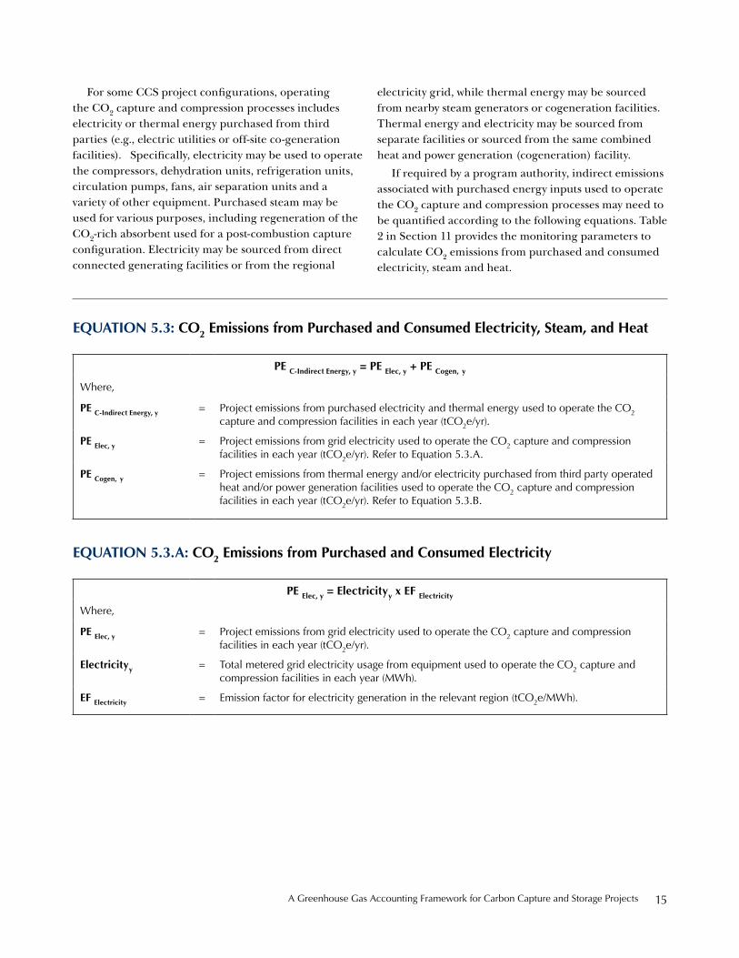
For some CCS project configurations, operating the CO2 capture and compression processes includes electricity or thermal energy purchased from third parties (e.g., electric utilities or off-site co-generation facilities). Specifically, electricity may be used to operate the compressors, dehydration units, refrigeration units, circulation pumps, fans, air separation units and a variety of other equipment. Purchased steam may be used for various purposes, including regeneration of the CO2-rich absorbent used for a post-combustion capture configuration. Electricity may be sourced from direct connected generating facilities or from the regional
electricity grid, while thermal energy may be sourced from nearby steam generators or cogeneration facilities. Thermal energy and electricity may be sourced from separate facilities or sourced from the same combined heat and power generation (cogeneration) facility.
If required by a program authority, indirect emissions associated with purchased energy inputs used to operate the CO2 capture and compression processes may need to be quantified according to the following equations. Table 2 in Section 11 provides the monitoring parameters to calculate CO2 emissions from purchased and consumed electricity, steam and heat.
eQuation 5.3: Co2 emissions from Purchased and Consumed electricity, steam, and Heat
Pe C-indirect energy, y = Pe elec, y + Pe Cogen, ywhere,
Pe C-indirect energy, y = project emissions from purchased electricity and thermal energy used to operate the Co2 capture and compression facilities in each year (tCo2e/yr).
Pe elec, y = project emissions from grid electricity used to operate the Co2 capture and compression facilities in each year (tCo2e/yr). refer to equation 5.3.A.
Pe Cogen, y = project emissions from thermal energy and/or electricity purchased from third party operated heat and/or power generation facilities used to operate the Co2 capture and compression facilities in each year (tCo2e/yr). refer to equation 5.3.b.
eQuation 5.3.a: Co2 emissions from Purchased and Consumed electricity
Pe elec, y = electricityy x eF electricity
where,
Pe elec, y = project emissions from grid electricity used to operate the Co2 capture and compression facilities in each year (tCo2e/yr).
electricityy = total metered grid electricity usage from equipment used to operate the Co2 capture and compression facilities in each year (Mwh).
eF electricity = emission factor for electricity generation in the relevant region (tCo2e/Mwh).
Center for Climate and energy solutions16
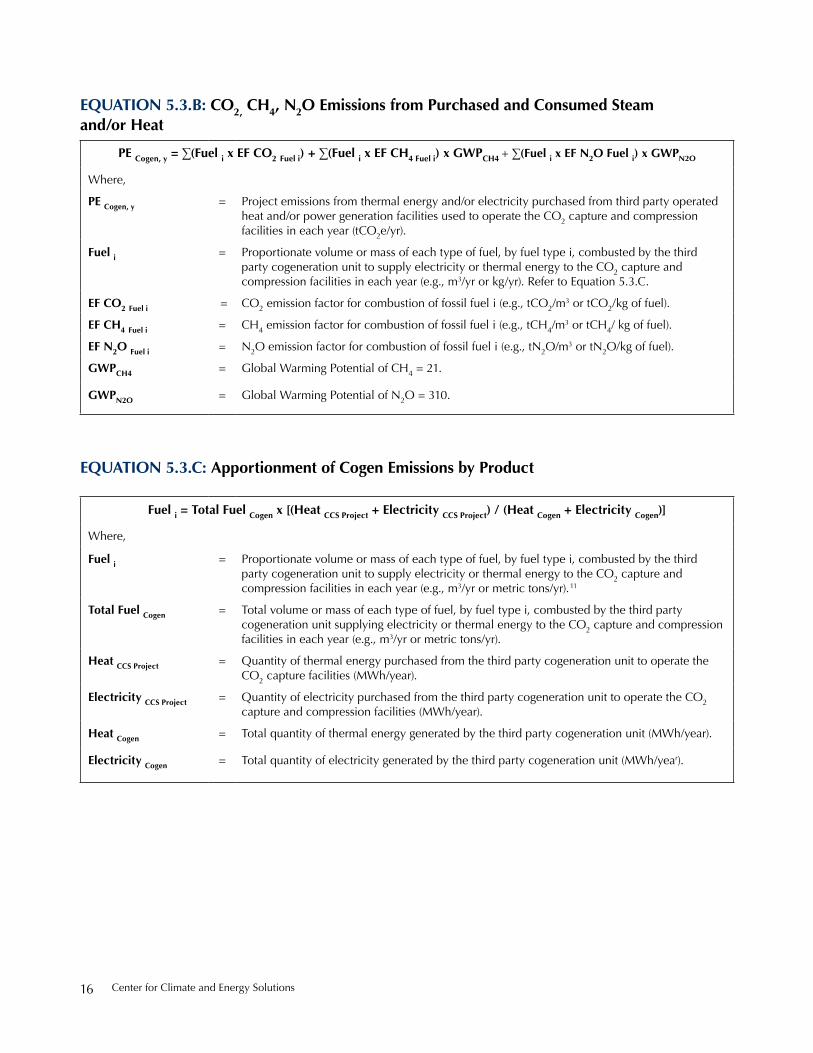
eQuation 5.3.b: Co2, CH4, n2o emissions from Purchased and Consumed steam and/or Heat
Pe Cogen, y = ∑(Fuel i x eF Co2 Fuel i) + ∑(Fuel i x eF CH4 Fuel i) x gwPCH4 + ∑(Fuel i x eF n2o Fuel i) x gwPn2o
where,
Pe Cogen, y = project emissions from thermal energy and/or electricity purchased from third party operated heat and/or power generation facilities used to operate the Co2 capture and compression facilities in each year (tCo2e/yr).
Fuel i = proportionate volume or mass of each type of fuel, by fuel type i, combusted by the third party cogeneration unit to supply electricity or thermal energy to the Co2 capture and compression facilities in each year (e.g., m3/yr or kg/yr). refer to equation 5.3.C.
eF Co2 Fuel i = Co2 emission factor for combustion of fossil fuel i (e.g., tCo2/m3 or tCo2/kg of fuel).
eF CH4 Fuel i = Ch4 emission factor for combustion of fossil fuel i (e.g., tCh4/m3 or tCh4/ kg of fuel).
eF n2o Fuel i = n2o emission factor for combustion of fossil fuel i (e.g., tn2o/m3 or tn2o/kg of fuel).
gwPCH4 = Global warming potential of Ch4 = 21.
gwPn2o = Global warming potential of n2o = 310.
eQuation 5.3.C: apportionment of Cogen emissions by Product
Fuel i = total Fuel Cogen x [(Heat CCs Project + electricity CCs Project) / (Heat Cogen + electricity Cogen)]
where,
Fuel i = proportionate volume or mass of each type of fuel, by fuel type i, combusted by the third party cogeneration unit to supply electricity or thermal energy to the Co2 capture and compression facilities in each year (e.g., m3/yr or metric tons/yr).11
total Fuel Cogen = total volume or mass of each type of fuel, by fuel type i, combusted by the third party cogeneration unit supplying electricity or thermal energy to the Co2 capture and compression facilities in each year (e.g., m3/yr or metric tons/yr).
Heat CCs Project = Quantity of thermal energy purchased from the third party cogeneration unit to operate the Co2 capture facilities (Mwh/year).
electricity CCs Project = Quantity of electricity purchased from the third party cogeneration unit to operate the Co2 capture and compression facilities (Mwh/year).
Heat Cogen = total quantity of thermal energy generated by the third party cogeneration unit (Mwh/year).
electricity Cogen = total quantity of electricity generated by the third party cogeneration unit (Mwh/year).
A Greenhouse Gas Accounting Framework for Carbon Capture and storage projects 17
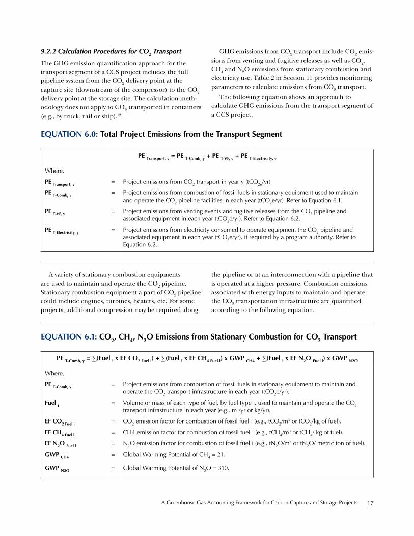
A variety of stationary combustion equipments are used to maintain and operate the CO2 pipeline. Stationary combustion equipment a part of CO2 pipeline could include engines, turbines, heaters, etc. For some projects, additional compression may be required along
the pipeline or at an interconnection with a pipeline that is operated at a higher pressure. Combustion emissions associated with energy inputs to maintain and operate the CO2 transportation infrastructure are quantified according to the following equation.
eQuation 6.0: total Project emissions from the transport segment
Pe transport, y = Pe t-Comb, y + Pe t-vF, y + Pe t-electricity, y
where,
Pe transport, y = project emissions from Co2 transport in year y (tCo2e/yr)
Pe t-Comb, y = project emissions from combustion of fossil fuels in stationary equipment used to maintain and operate the Co2 pipeline facilities in each year (tCo2e/yr). refer to equation 6.1.
Pe t-vF, y = project emissions from venting events and fugitive releases from the Co2 pipeline and associated equipment in each year (tCo2e/yr). refer to equation 6.2.
Pe t-electricity, y = project emissions from electricity consumed to operate equipment the Co2 pipeline and associated equipment in each year (tCo2e/yr), if required by a program authority. refer to equation 6.2.
eQuation 6.1: Co2, CH4, n2o emissions from stationary Combustion for Co2 transport
Pe t-Comb, y = ∑(Fuel i x eF Co2 Fuel i) + ∑(Fuel i x eF CH4 Fuel i) x gwP CH4 + ∑(Fuel i x eF n2o Fuel i) x gwP n2o
where,
Pe t-Comb, y = project emissions from combustion of fossil fuels in stationary equipment to maintain and operate the Co2 transport infrastructure in each year (tCo2e/yr).
Fuel i = Volume or mass of each type of fuel, by fuel type i, used to maintain and operate the Co2 transport infrastructure in each year (e.g., m3/yr or kg/yr).
eF Co2 Fuel i = Co2 emission factor for combustion of fossil fuel i (e.g., tCo2/m3 or tCo2/kg of fuel).
eF CH4 Fuel i = Ch4 emission factor for combustion of fossil fuel i (e.g., tCh4/m3 or tCh4/ kg of fuel).
eF n2o Fuel i = n2o emission factor for combustion of fossil fuel i (e.g., tn2o/m3 or tn2o/ metric ton of fuel).
gwP CH4 = Global warming potential of Ch4 = 21.
gwP n2o = Global warming potential of n2o = 310.
9.2.2 Calculation Procedures for CO2 Transport
The GHG emission quantification approach for the transport segment of a CCS project includes the full pipeline system from the CO2 delivery point at the capture site (downstream of the compressor) to the CO2 delivery point at the storage site. The calculation meth-odology does not apply to CO2 transported in containers (e.g., by truck, rail or ship).12
GHG emissions from CO2 transport include CO2 emis-sions from venting and fugitive releases as well as CO2, CH4 and N2O emissions from stationary combustion and electricity use. Table 2 in Section 11 provides monitoring parameters to calculate emissions from CO2 transport.
The following equation shows an approach to calculate GHG emissions from the transport segment of a CCS project.

Center for Climate and energy solutions18
This methodology presents a mass balance approach to calculate transport-related vented and fugitive CO2 emissions. Venting and fugitive emissions of CO2 are grouped together in the mass balance determination.13
Alternatively, in situations where a mass balance method might not appropriately apply (for instance, the uncertainty of the measured values is greater than the magnitude of the quantified emissions) vented and fugitive emissions may be estimated using a component count method. To use the component count method an inventory of equipment (fittings, valves, etc.) is compiled
in order to apply fugitive emission factors to estimate emissions from the pipeline. Venting events must also be logged to estimate venting emissions (e.g., intentional pipeline releases). The component-count method to calculate vented and fugitive emissions is presented in the CO2 storage segment calculation procedures (see Equation 7.2).
The following equation is used to quantify venting and fugitive emissions from the CO2 pipeline according to the mass balance method.
eQuation 6.2: vented and Fugitive Co2 emissions from Co2 transport
Pe t-vF, y = Co2 received Capture, y - Co2 supplied storage, y
where,
Pe t-vF y = project emissions from venting events and fugitive releases from the Co2 pipeline and associated equipment in each year (tCo2e/yr).
Co2 received Capture, y = Co2 captured and input into the pipeline, metered at the point of transfer with the capture site in each year (tCo2/yr). refer to equation 6.2.A.
Co2 supplied storage, y = Co2 supplied to the storage site operator, metered at the point of transfer with the storage site in each year (tCo2/yr). refer to equation 6.2.b.
eQuation 6.2.a: Co2 Captured and input into Co2 Pipeline
Co2 received Capture, y = vol. gas received, y x %Co2 x rCo2
where,
Co2 received Capture, y = Co2 captured and input into the pipeline, metered at the point of transfer with the capture site in each year (tCo2/yr).
vol. gas received, y = Co2 captured and input into the pipeline, metered at the point of transfer with the capture site in each year (m3 Co2/yr).
%Co2 = % Co2 in the gas stream measured at the point of transfer with the capture site (% volume).
rCo2 = density of Co2 at standard conditions (metric ton/m3).
A Greenhouse Gas Accounting Framework for Carbon Capture and storage projects 19
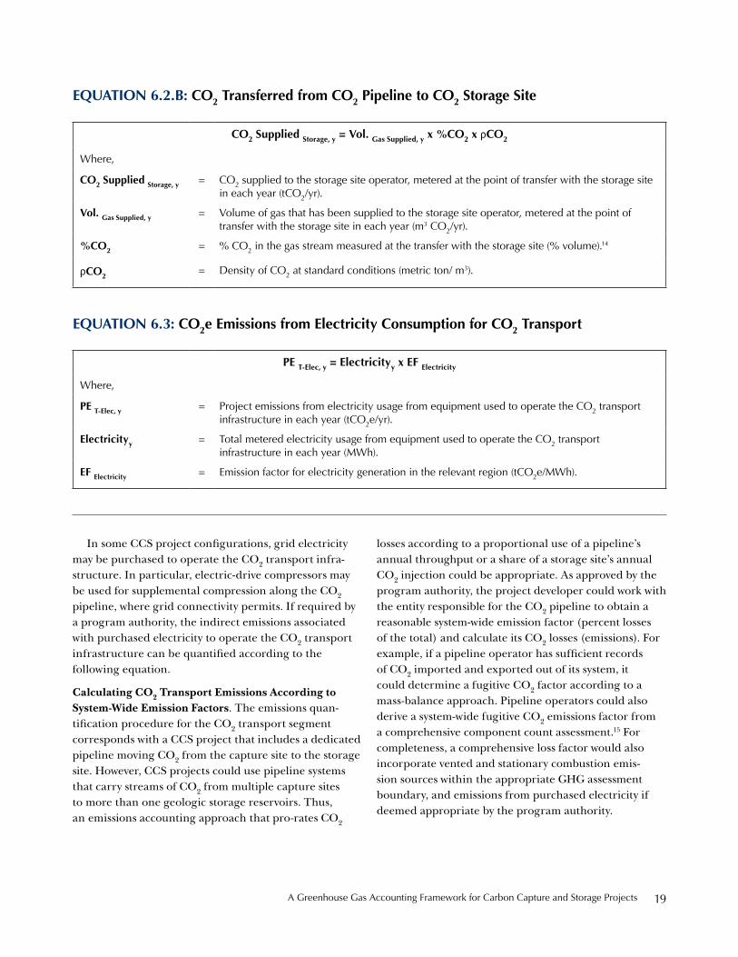
In some CCS project configurations, grid electricity may be purchased to operate the CO2 transport infra-structure. In particular, electric-drive compressors may be used for supplemental compression along the CO2 pipeline, where grid connectivity permits. If required by a program authority, the indirect emissions associated with purchased electricity to operate the CO2 transport infrastructure can be quantified according to the following equation.
Calculating CO2 Transport Emissions According to System-Wide Emission Factors. The emissions quan-tification procedure for the CO2 transport segment corresponds with a CCS project that includes a dedicated pipeline moving CO2 from the capture site to the storage site. However, CCS projects could use pipeline systems that carry streams of CO2 from multiple capture sites to more than one geologic storage reservoirs. Thus, an emissions accounting approach that pro-rates CO2
losses according to a proportional use of a pipeline’s annual throughput or a share of a storage site’s annual CO2 injection could be appropriate. As approved by the program authority, the project developer could work with the entity responsible for the CO2 pipeline to obtain a reasonable system-wide emission factor (percent losses of the total) and calculate its CO2 losses (emissions). For example, if a pipeline operator has sufficient records of CO2 imported and exported out of its system, it could determine a fugitive CO2 factor according to a mass-balance approach. Pipeline operators could also derive a system-wide fugitive CO2 emissions factor from a comprehensive component count assessment.15 For completeness, a comprehensive loss factor would also incorporate vented and stationary combustion emis-sion sources within the appropriate GHG assessment boundary, and emissions from purchased electricity if deemed appropriate by the program authority.
eQuation 6.2.b: Co2 transferred from Co2 Pipeline to Co2 storage site
Co2 supplied storage, y = vol. gas supplied, y x %Co2 x rCo2
where,
Co2 supplied storage, y = Co2 supplied to the storage site operator, metered at the point of transfer with the storage site in each year (tCo2/yr).
vol. gas supplied, y = Volume of gas that has been supplied to the storage site operator, metered at the point of transfer with the storage site in each year (m3 Co2/yr).
%Co2 = % Co2 in the gas stream measured at the transfer with the storage site (% volume).14
rCo2 = density of Co2 at standard conditions (metric ton/ m3).
eQuation 6.3: Co2e emissions from electricity Consumption for Co2 transport
Pe t-elec, y = electricityy x eF electricity
where,
Pe t-elec, y = project emissions from electricity usage from equipment used to operate the Co2 transport infrastructure in each year (tCo2e/yr).
electricityy = total metered electricity usage from equipment used to operate the Co2 transport infrastructure in each year (Mwh).
eF electricity = emission factor for electricity generation in the relevant region (tCo2e/Mwh).

Center for Climate and energy solutions20
9.2.3 Calculation Procedures for CO2 Storage in Non-Producing Formations
The GHG quantification method for CO2 injection and storage in non-producing formations (i.e., saline aqui-fers) covers direct CO2, CH4, and N2O emissions from stationary combustion, CO2 emissions from venting and fugitive releases from injection wells and other surface equipment, and, if required by a program authority, indi-rect CO2 emissions from electricity use. The methodology also accounts for CO2 emissions that may escape from the geologic storage formation to the atmosphere, in the event such leaks are detected by the CO2 storage site operator. GHG emission sources at a non-producing CO2 storage site include all surface facilities for CO2 receiving and handling located between the point of transfer with the CO2 pipeline up to and including the injection wells, injection wells and the CO2 storage reservoir.
CO2e emissions from energy inputs to operate the CO2 injection and storage facilities are accounted for using common quantification methods based on the amount and types of energy inputs. Vented CO2 emis-sions from surface facilities are quantified on an event basis. Fugitive CO2 emissions from injection wells and surface facilities are calculated according to a compo-nent count approach. The method to calculate leaked CO2 to the atmosphere from the underground storage reservoir, should this occur, would be reservoir-specific.
The following equation is used to calculate the emissions from CO2 storage in non-producing forma-tions. Table 2 in Section 11 provides the calculation monitoring parameters.
eQuation 7.0: total Project emissions from Co2 storage at non-Producing reservoirs
Pe storage-nP, y = Pe s-nP-Comb, y + Pe s-nP-vent, y + Pes-nP-Fug, y + Pe s-nP-leakage, y + Pe s-nP- elec, y
where,
Pe storage-nP, y = project emissions from Co2 injection and storage in non-producing formations in each year (tCo2e/yr).
Pe s-nP-Comb, y = project emissions from combustion of fossil fuels in stationary equipment used to maintain and operate the Co2 injection and storage facilities in each year (tCo2e/yr). refer to equation 7.1.
Pe s-nP-vent, y = project emissions from venting of Co2 at the injection wells or other surface facilities located between the point of transfer with the Co2 pipeline and the injection wells in the non-producing formation in each year (tCo2e/yr). refer to equation 7.2.
Pe s-nP-Fug, y = project emissions from fugitive releases of Co2 at the injection wells or other surface facilities located between the point of transfer with the Co2 pipeline and the injection wells in the non-producing formation in each year (tCo2e/yr). refer to equation 7.3.
Pe s-nP-leakage, y = project emissions from leakage of injected Co2 from the geologic storage reservoir to the atmosphere in each year (tCo2/yr).
For information on accounting for Co2 leakage emissions from geologic storage formations to the atmosphere see section 9.2.5.
Pe s-nP-elec, y = project emissions from grid electricity used to operate equipment at the injection wells and surface facilities at the storage site in the non-producing formation in each year (tCo2e/yr), if required by a program authority. refer to equation 7.4.
A Greenhouse Gas Accounting Framework for Carbon Capture and storage projects 21
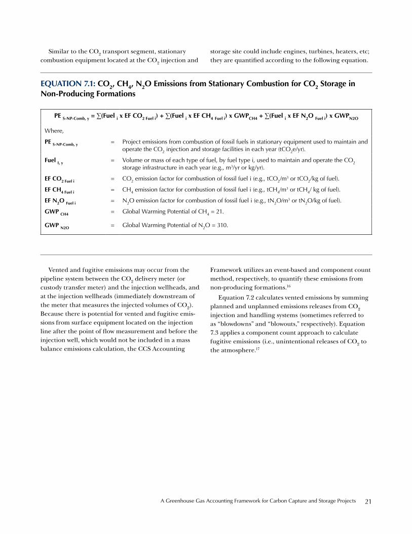
Similar to the CO2 transport segment, stationary combustion equipment located at the CO2 injection and
storage site could include engines, turbines, heaters, etc; they are quantified according to the following equation.
eQuation 7.1: Co2, CH4, n2o emissions from stationary Combustion for Co2 storage in non-Producing Formations
Pe s-nP-Comb, y = ∑(Fuel i x eF Co2 Fuel i) + ∑(Fuel i x eF CH4 Fuel i) x gwPCH4 + ∑(Fuel i x eF n2o Fuel i) x gwPn2o
where,
Pe s-nP-Comb, y = project emissions from combustion of fossil fuels in stationary equipment used to maintain and operate the Co2 injection and storage facilities in each year (tCo2e/yr).
Fuel i, y = Volume or mass of each type of fuel, by fuel type i, used to maintain and operate the Co2 storage infrastructure in each year (e.g., m3/yr or kg/yr).
eF Co2 Fuel i = Co2 emission factor for combustion of fossil fuel i (e.g., tCo2/m3 or tCo2/kg of fuel).
eF CH4 Fuel i = Ch4 emission factor for combustion of fossil fuel i (e.g., tCh4/m3 or tCh4/ kg of fuel).
eF n2o Fuel i = n2o emission factor for combustion of fossil fuel i (e.g., tn2o/m3 or tn2o/kg of fuel).
gwP CH4 = Global warming potential of Ch4 = 21.
gwP n2o = Global warming potential of n2o = 310.
Vented and fugitive emissions may occur from the pipeline system between the CO2 delivery meter (or custody transfer meter) and the injection wellheads, and at the injection wellheads (immediately downstream of the meter that measures the injected volumes of CO2). Because there is potential for vented and fugitive emis-sions from surface equipment located on the injection line after the point of flow measurement and before the injection well, which would not be included in a mass balance emissions calculation, the CCS Accounting
Framework utilizes an event-based and component count method, respectively, to quantify these emissions from non-producing formations.16
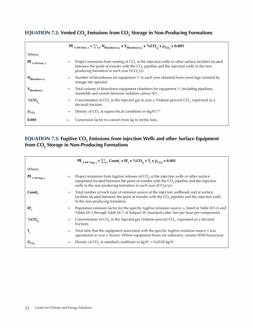
Equation 7.2 calculates vented emissions by summing planned and unplanned emissions releases from CO2 injection and handling systems (sometimes referred to as “blowdowns” and “blowouts,” respectively). Equation 7.3 applies a component count approach to calculate fugitive emissions (i.e., unintentional releases of CO2 to the atmosphere.17
Center for Climate and energy solutions22
eQuation 7.2: vented Co2 emissions from Co2 storage in non-Producing Formations
Pe s-nP-vent, y = ∑Ii=1 nblowdown i,y x vblowdown i,y x %Co2i
x Co2 x 0.001
where,
Pe s-nP-vent, y = project emissions from venting of Co2 at the injection wells or other surface facilities located between the point of transfer with the Co2 pipeline and the injection wells in the non-producing formation in each year (tCo2/yr).
nblowdown i,y = number of blowdowns for equipment ‘i’ in each year obtained from event logs retained by storage site operator.
vblowdown i = total volume of blowdown equipment chambers for equipment ‘i’ (including pipelines, manifolds and vessels between isolation valves) (ft3).
%Co2i= Concentration of Co2 in the injected gas in year y (Volume percent Co2, expressed as a
decimal fraction).
Co2= density of Co2 at supercritical conditions in (kg/ft3).18
0.001 = Conversion factor to convert from kg to metric tons.
eQuation 7.3: Fugitive Co2 emissions from injection wells and other surface equipment from Co2 storage in non-Producing Formations
Pe s-nP -Fug, y = ∑Ss=1 Counts x eFs x %Co2i
x ts x Co2 x 0.001
where,
Pe s-nP-Fug, y = project emissions from fugitive releases of Co2 at the injection wells or other surface equipment located between the point of transfer with the Co2 pipeline and the injection wells in the non-producing formation in each year (tCo2e/yr).
Counts = total number of each type of emission source at the injection wellheads and at surface facilities located between the point of transfer with the Co2 pipeline and the injection wells in the non-producing formation.
eFs = Population emission factor for the specific fugitive emission source, s, listed in Table W1-A and tables w-3 through table w-7 of subpart w (standard cubic feet per hour per component).
%Co2i= Concentration of Co2 in the injected gas (Volume percent Co2, expressed as a decimal
fraction).
ts = Total time that the equipment associated with the specific fugitive emission source s was operational in year y (hours). where equipment hours are unknown, assume 8760 hours/year.
Co2= density of Co2 at standard conditions in kg/ft3 = 0.0538 kg/ft3.

A Greenhouse Gas Accounting Framework for Carbon Capture and storage projects 23
9.2.4 Calculation Procedures for CO2 Storage in Producing Formations
The emissions calculation procedures for CO2 storage at producing formations (i.e., enhanced oil and gas recovery sites) cover direct CO2, CH4, and N2O emis-sions from stationary combustion; CO2 emissions from venting and fugitive releases to the atmosphere; and, if required by program authorities, indirect CO2e emissions from purchased electricity use. GHG sources include CO2 receiving, injecting, recycling and re-injection equipment; CO2 injection and production wells, hydrocarbon processing and storage facilities; and the CO2 storage reservoir.
Similar to non-producing formations, the emissions quantification methodology for CO2 storage in enhanced oil and gas recovery formations includes all emissions sources located between the point of transfer with the CO2 pipeline up to and including the injection wells. It also incorporates producing wells and surface facilities related to the hydrocarbon gathering, storage and sepa-ration facilities and the infrastructure used to process, purify and compress CO2 and other gases produced from the formation, and re-inject it back into the formation. Additionally, CO2 entrained in or dissolved in hydro-carbons (crude oil or natural gas) or waste water that is removed or distributed off-site (e.g., sold, disposed of and/or not re-injected) is accounted for as a source of fugitive emissions.
Emissions from energy inputs to operate the facilities at enhanced oil and gas recovery formations are accounted for by using common quantification methods based on the quantities and types of energy inputs. Vented CO2 emissions from surface facilities are quantified on an event basis. Fugitive CO2 emissions from injection wells and surface facilities are calculated according to a component count approach. The method to calculate leaked CO2 from the geologic storage reservoir to the atmosphere, should it occur, would be reservoir-specific.
The CCS Accounting Framework does not treat CO2 produced from wells at enhanced oil or gas recovery operations that is recycled and re-injection into the storage formation as an emission, provided the CO2 remains within the closed loop system and thus prevented from entering the atmosphere. Unintentional CO2 releases from the recycle system (including from production wells, gas separation and cleaning equip-ment) are treated as fugitive emissions and accounted for in Equation 8.3. Intentionally vented CO2 in the recycle system (for operational purposes) is treated as a vented emission and accounted for in Equation 8.2.
The following equation outlines the methods for calculating emissions from CO2 storage in producing formations. Table 2 in Section 11 provides monitoring parameters for calculating emissions from CO2 storage in producing formations.
Grid electricity may be used to operate the CO2 injec-tion wells, storage infrastructure and related monitoring equipment at the non-producing formation. If required
by program authorities, the indirect emissions associated with purchased electricity are quantified according to the following equation.
eQuation 7.4: Co2e emissions from electricity Consumption for Co2 storage in non-Producing Formations
Pe s-nP-elec, y = electricityy x eF electricity
where,
Pe s-nP-elec, y = project emissions from electricity used to operate equipment at the Co2 storage site in the non-producing formation in year y (tCo2e/yr).
electricityy = total metered electricity usage from equipment used to operate the storage site in the non-producing formation in year y (Mwh).
eF electricity = emission factor for electricity generation in the relevant region (tCo2e/Mwh).
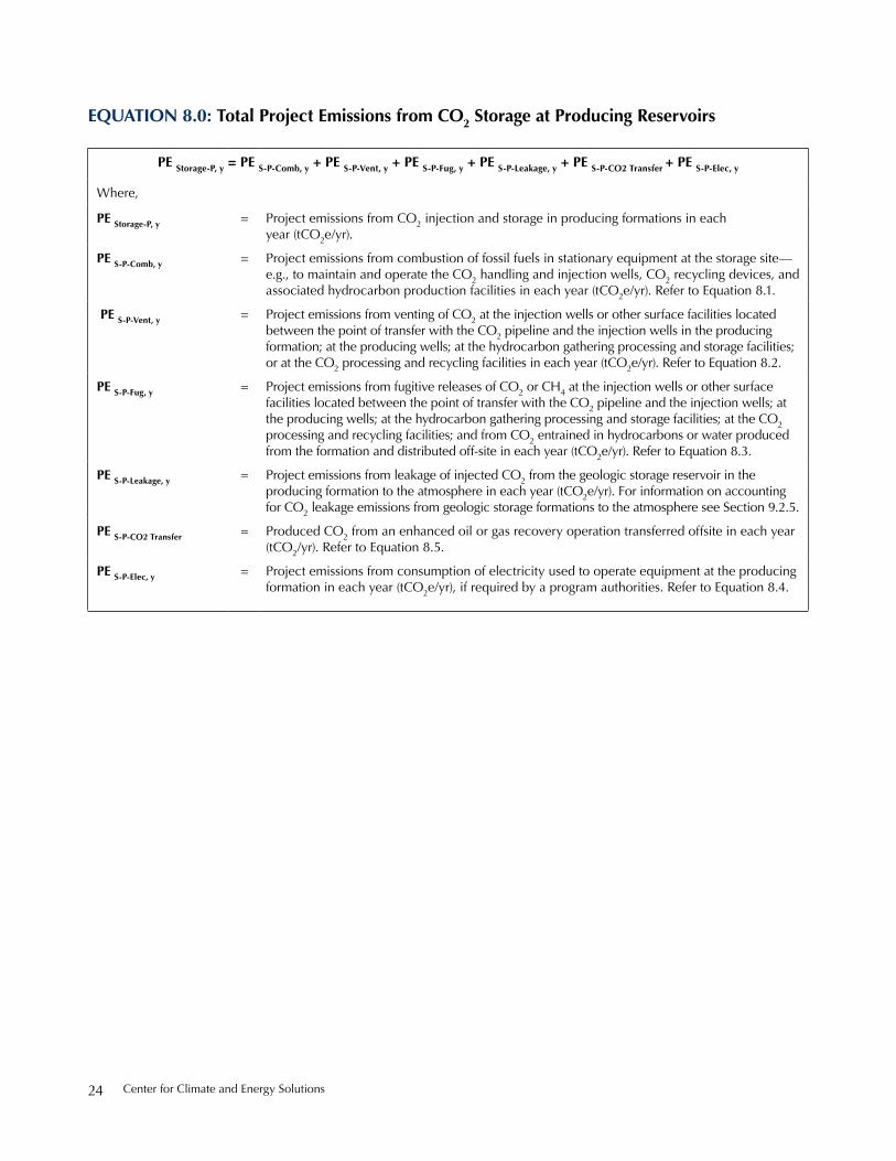
Center for Climate and energy solutions24
eQuation 8.0: total Project emissions from Co2 storage at Producing reservoirs
Pe storage-P, y = Pe s-P-Comb, y + Pe s-P-vent, y + Pe s-P-Fug, y + Pe s-P-leakage, y + Pe s-P-Co2 transfer + Pe s-P-elec, y
where,
Pe storage-P, y = project emissions from Co2 injection and storage in producing formations in each year (tCo2e/yr).
Pe s-P-Comb, y = project emissions from combustion of fossil fuels in stationary equipment at the storage site—e.g., to maintain and operate the Co2 handling and injection wells, Co2 recycling devices, and associated hydrocarbon production facilities in each year (tCo2e/yr). refer to equation 8.1.
Pe s-P-vent, y = project emissions from venting of Co2 at the injection wells or other surface facilities located between the point of transfer with the Co2 pipeline and the injection wells in the producing formation; at the producing wells; at the hydrocarbon gathering processing and storage facilities; or at the Co2 processing and recycling facilities in each year (tCo2e/yr). refer to equation 8.2.
Pe s-P-Fug, y = project emissions from fugitive releases of Co2 or Ch4 at the injection wells or other surface facilities located between the point of transfer with the Co2 pipeline and the injection wells; at the producing wells; at the hydrocarbon gathering processing and storage facilities; at the Co2 processing and recycling facilities; and from Co2 entrained in hydrocarbons or water produced from the formation and distributed off-site in each year (tCo2e/yr). refer to equation 8.3.
Pe s-P-leakage, y = project emissions from leakage of injected Co2 from the geologic storage reservoir in the producing formation to the atmosphere in each year (tCo2e/yr). For information on accounting for Co2 leakage emissions from geologic storage formations to the atmosphere see section 9.2.5.
Pe s-P-Co2 transfer = produced Co2 from an enhanced oil or gas recovery operation transferred offsite in each year (tCo2/yr). refer to equation 8.5.
Pe s-P-elec, y = project emissions from consumption of electricity used to operate equipment at the producing formation in each year (tCo2e/yr), if required by a program authorities. refer to equation 8.4.

A Greenhouse Gas Accounting Framework for Carbon Capture and storage projects 25
Various types of stationary combustion equipment may be used to maintain and operate the CO2 injec-tion, storage, processing and recycling facilities and to operate the enhanced oil and gas recovery facilities (e.g.,
batteries, gathering systems, oil-water-gas separators). The following equation is used to quantify GHG emis-sions from all stationary fossil fuel-driven equipment used to operate the CO2 injection and storage facilities. 19
eQuation 8.1: Co2, CH4, n2o emissions from stationary Combustion for Co2 storage at Producing Formations
Pe s-nP-Comb, y = ∑(Fuel i x eF Co2 Fuel i) + ∑(Fuel i x eF CH4 Fuel i) x gwPCH4 + ∑(Fuel i x eF n2o Fuel i) x gwPn2o
where,
Pe s-P-Comb, y = project emissions from combustion of fossil fuels in stationary equipment at the producing storage site—e.g., to maintain and operate the Co2 handling and injection wells, Co2 recycling devices, and associated hydrocarbon production facilities in each year (tCo2e/yr). refer to equation 8.1.
Fuel i, y = Volume or mass of each type of fuel, by fuel type i, used to inspect, maintain and operate the Co2 storage infrastructure and hydrocarbon production facilities in each year (e.g., m3/yr or kg/yr).
eF Co2 Fuel i = Co2 emission factor for combustion of fossil fuel i (e.g., tCo2/m3 or tCo2/kg of fuel).
eF CH4 Fuel i = Ch4 emission factor for combustion of fossil fuel i (e.g., tCh4/m3 or tCh4/kg of fuel).
eF n2o Fuel i = n2o emission factor for combustion of fossil fuel i (e.g., tn2o/m3 or tn2o/kg of fuel).
gwP CH4 = Global warming potential of Ch4 = 21.
gwP n2o = Global warming potential of n2o = 310.

Center for Climate and energy solutions26
Venting may occur at the injection wells or at other surface facilities, located between the CO2 transfer meter at the pipeline and the injection wells. It could also happen at the production wells, the hydrocarbon production and storage facilities or at the facilities used to process and recycle the produced CO2 for re-injection into the formation. Planned venting may take place
during shutdowns and maintenance work, while unplanned venting may occur during upsets to opera-tions. Venting events should be logged.
The following equation can be used to calculate vented emissions from the injection wells and other surface facilities at the CO2 storage site.
eQuation 8.2: vented Co2e emissions from Co2 storage at Producing Formations
Pe s-P-vent, y = ∑Ii=1 nblowdown i x vblowdown i x %gHgi x gHg x gwP x 0.001
where,
Pe s-P-vent, y = project emissions from vented Co2 at the injection wells or other surface facilities located between the point of transfer with the Co2 pipeline and the injection wells in the producing formation; at the producing wells; at the hydrocarbon gathering processing and storage facilities; or at the Co2 processing and recycling facilities in each year (tCo2e/yr).
nblowdown i = number of blowdowns for equipment i in each year, obtained from blowdown event logs retained by storage site operator.
vblowdown i = total volume of blowdown equipment chambers for equipment i (including pipelines, manifolds and vessels between isolation valves) (m3, ft3).
%gHg i = Concentration of GhG ‘i’ in the injected gas in year y (Volume percent GhG, expressed as a decimal fraction).
gHg i = density of relevant GhG (Co2 or Ch4) at standard conditions in kg/m3 or kg/ft3.20
gwP = 100 year Global warming potential of relevant GhG (Co2 =1 and Ch4 =21).
0.001 = Conversion factor to convert from kg to metric tons.

A Greenhouse Gas Accounting Framework for Carbon Capture and storage projects 27
Fugitive emissions of CO2, and in some cases methane, may occur at the injection wells or at other surface facilities, located between the CO2 pipeline transfer meter and the injection wells. Fugitive emissions could also happen at production wells, the hydrocarbon production and storage facilities, and/or at the facili-ties used to process and recycle the produced CO2 for re-injection into the formation. Fugitive emission sources could include fittings, flanges, valves, connectors, meters, and headers (large pipes that mix the oil stream from multiple wellheads). Fugitive emissions may also result from the release of residual CO2 entrained or dissolved
in produced oil, water or gas that is transferred from the hydrocarbon recovery facilities to downstream users.
Fugitive CO2 and CH4 emissions from injection wells and other surface equipment are calculated on a compo-nent count approach. Fugitive emissions of CO2 entrained in or dissolved in hydrocarbon liquids or gases or water produced from the formation and distributed off-site are calculated based on quantities of crude oil, water and gas produced and the CO2 content of each product.
The following equation is used to calculate fugitive emissions from the injection wells and other surface facilities at the CO2 storage site.
eQuation 8.3: Fugitive Co2e emissions from wells and surface equipment at Producing Formations
Pe s-P -Fugitive, y = Pe s-P -Fug-equipment, y + Pe s-P -Fug-entrained Co2, y
where,
Pe s-P-Fugitive, y = project emissions from fugitive releases of Co2 or Ch4 at the injection wells or other surface facilities located between the point of transfer with the Co2 pipeline and the injection wells; at the producing wells; at the hydrocarbon gathering processing and storage facilities; at the Co2 processing and recycling facilities; and from Co2 entrained in hydrocarbons or water produced from the formation and distributed off-site in each year (tCo2e/yr).
Pe s-P -Fug-equipment, y = Fugitive emissions of Co2 (and Ch4 if relevant) from equipment located at the injection wells or other surface facilities located between the point of transfer with the Co2 pipeline and the injection wells; at the producing wells; at the hydrocarbon gathering processing and storage facilities; and at the Co2 processing and recycling facilities in each year (tCo2e/yr). refer to equation 8.3.A.
Pe s-P -Fug-entrained Co2, y = Fugitive emissions of Co2 entrained in or dissolved in hydrocarbon liquids or gases or water produced from the formation and distributed off-site (sold or otherwise disposed of and not re-injected) in each year (tCo2/yr). refer to equation 8.3.b.

Center for Climate and energy solutions28
eQuation 8.3.a: Co2 & CH4 Fugitive emissions from equipment leaks at Producing Formations
Pe s-P -Fug-equipment, y = ∑i ∑S
s=1 Counts x eFs x %gHgi x ts x gHg x gwP x 0.001
where,
Pe s-P -Fug-equipment, y = Fugitive of GhG ‘i’ (Co2 and Ch4, if relevant) from equipment located at the injection wells or other surface facilities located between the point of transfer with the Co2 pipeline and the injection wells; at the producing wells; at the hydrocarbon gathering processing and storage facilities; and at the Co2 processing and recycling facilities in each year (tCo2e/yr).
Counts = total number of each type of emission source at the injection wellheads and at surface facili-ties located between the point of transfer with the Co2 pipeline and the injection wells; at the producing wells; at the hydrocarbon gathering processing and storage facilities; and at the Co2 processing and recycling facilities.
eFs = Population emission factor for the specific fugitive emission source, ‘s’, in Table W1-A and tables w-3 through table w-7 of subpart w (standard cubic feet per hour per component).
%gHgi = Concentration of GhG ‘i’ (Co2 or Ch4) in the injected or produced gas (Volume percent Co2 or Ch4, expressed as a decimal fraction).
ts = Total time that the equipment associated with the specific fugitive emission source s was operational in year y (hours). where equipment hours are unknown, assume 8760 hours/year.
gHg = density of relevant GhG (Co2 or Ch4) at standard conditions in kg/m3 or kg/ft3.
gwP = 100 year Global warming potential of relevant GhG (Co2 =1 and Ch4 =21).
0.001 = Conversion factor to convert from kg to metric tons.

A Greenhouse Gas Accounting Framework for Carbon Capture and storage projects 29
Purchased electricity may be used to operate pumps, compressors and other equipment at the injection wells and producing wells; at oil and gas gathering, storage and processing facilities (e.g., oil-water-gas separators); or at CO2 processing, compression, recycling and re-injection facilities.
For example, many enhanced oil and gas recovery projects install additional water pumping capacity to alternate water injection and CO2 injection (water alternating gas (WAG) injection), which may also require electricity. Electric compression could be used to recycle produced CO2 and other gases for re-injection into the formation. In addition to the recycle compressors,
additional electric-drive equipment may be used to operate vapor recovery units to recover vapors from oil and water tanks, to operate flash gas compressors which increase the pressure of the recovered vapors for recy-cling, to operate glycol dehydrators and glycol circulation pumps that remove moisture from the produced gas, and to operate other auxiliary equipment such as instrument air compressors and cooling fans.
If required by a program authority, indirect GHG emissions from with purchased electricity used to operate equipment at the enhanced oil and gas recovery operations are quantified according to the following equation.
eQuation 8.3.b: Co2 Fugitive emissions entrained in Produced Hydrocarbons at Producing Formations
Pe s-P-Fug-entrained Co2, y = (vol. gas sold y x % Co2 gas sold y x r Co2 x 0.001) + (mass water Prod x mass Frac Co2 in water) + (mass Hydrocarbons Prod x mass Frac Co2 in oil)
where,
Pes-P-Fug-entrained Co2, y = Fugitive emissions or other losses of Co2 entrained or dissolved in crude oil/other hydrocarbons, produced water and natural gas that have been separated from the produced Co2 for sale or disposal. Calculated based on quantities of crude oil, water and gas produced and the Co2 content of each product.
vol. gas sold y = Volume of natural gas or fuel gas, produced from the formation that Co2 is being injected into, that is sold to third parties or input into a natural gas pipeline in year y (m3/yr, measured at standard conditions).
% Co2 gas sold y = % Co2 in the natural gas or fuel gas that is sold to third parties or input into a natural gas pipeline, in year y (% volume).
r Co2 = density of Co2 at standard conditions (kg ton/m3 or ft3).
0.001 = Conversion factor to convert from kg to metric tons.
mass water Prod = Mass of water produced from the formation that Co2 is being injected into, that is disposed of or otherwise not-re-injected back into the formation (metric tons/yr).
mass Frac Co2 in water = Mass fraction of Co2 in the water produced from the formation (unitless).
mass Hydrocarbons Prod = Mass of crude oil and other hydrocarbons produced from the formation that Co2 is being injected into (metric tons/year).
mass Frac Co2 in oil = Mass fraction of Co2 in the crude oil and other hydrocarbons produced from the formation (unitless).
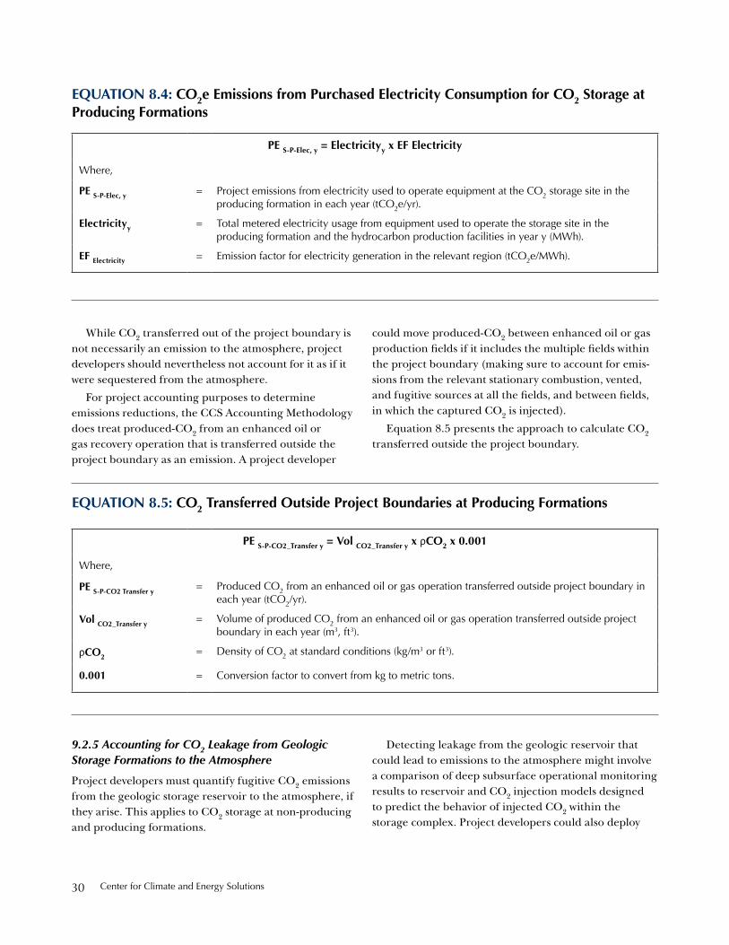
Center for Climate and energy solutions30
While CO2 transferred out of the project boundary is not necessarily an emission to the atmosphere, project developers should nevertheless not account for it as if it were sequestered from the atmosphere.
For project accounting purposes to determine emissions reductions, the CCS Accounting Methodology does treat produced-CO2 from an enhanced oil or gas recovery operation that is transferred outside the project boundary as an emission. A project developer
could move produced-CO2 between enhanced oil or gas production fields if it includes the multiple fields within the project boundary (making sure to account for emis-sions from the relevant stationary combustion, vented, and fugitive sources at all the fields, and between fields, in which the captured CO2 is injected).
Equation 8.5 presents the approach to calculate CO2 transferred outside the project boundary.
eQuation 8.4: Co2e emissions from Purchased electricity Consumption for Co2 storage at Producing Formations
Pe s-P-elec, y = electricityy x eF electricity
where,
Pe s-P-elec, y = project emissions from electricity used to operate equipment at the Co2 storage site in the producing formation in each year (tCo2e/yr).
electricityy = total metered electricity usage from equipment used to operate the storage site in the producing formation and the hydrocarbon production facilities in year y (Mwh).
eF electricity = emission factor for electricity generation in the relevant region (tCo2e/Mwh).
eQuation 8.5: Co2 transferred outside Project boundaries at Producing Formations
Pe s-P-Co2_transfer y = vol Co2_transfer y x rCo2 x 0.001
where,
Pe s-P-Co2 transfer y = produced Co2 from an enhanced oil or gas operation transferred outside project boundary in each year (tCo2/yr).
vol Co2_transfer y = Volume of produced Co2 from an enhanced oil or gas operation transferred outside project boundary in each year (m3, ft3).
rCo2 = density of Co2 at standard conditions (kg/m3 or ft3).
0.001 = Conversion factor to convert from kg to metric tons.
9.2.5 Accounting for CO2 Leakage from Geologic Storage Formations to the Atmosphere
Project developers must quantify fugitive CO2 emissions from the geologic storage reservoir to the atmosphere, if they arise. This applies to CO2 storage at non-producing and producing formations.
Detecting leakage from the geologic reservoir that could lead to emissions to the atmosphere might involve a comparison of deep subsurface operational monitoring results to reservoir and CO2 injection models designed to predict the behavior of injected CO2 within the storage complex. Project developers could also deploy

A Greenhouse Gas Accounting Framework for Carbon Capture and storage projects 31
monitoring devices to detect leakage of CO2 at the surface, in which a comparison would be made between surface monitoring data and natural variations in CO2 levels from organic matter and vegetation in the local environment. Other monitoring tools could also provide information on site performance indicators, the location and size of the CO2 plume, environmental receptors, and other factors.
Project developers and program authorities should work together to establish CO2 detection thresholds to calibrate monitoring systems in a manner that provides confidence in the monitoring program’s ability to accurately confirm the effectiveness of the CO2 storage complex.21 Section 12 provides a brief overview of monitoring CO2 in geologic formations, by project development phase; it also includes a set of resources that provide guidance for monitoring CO2 in geologic formations.
Examples of conduits for CO2 leaks to the atmosphere include CO2 injection wells, oil or gas production wells (if applicable), monitoring wells and abandoned wells;22 CO2 could also escape the geologic containment complex through faults and fissures. However, for properly selected, operated, and closed CO2 storage operations, fugitive CO2 emissions from the geologic reservoir to the atmosphere should not occur.
For a CO2 storage site in compliance with its CO2 injection permit the value of the “CO2-z” term in Equation 9 should be zero. That is, it is reasonable to expect that leakage to the atmosphere is not a threat and zero is an acceptable value for the “CO2-z” term in Equation 9 if:
• “Conformance monitoring systems” show that the behavior of CO2 within the injection zone in the
storage complex agrees with modeled predictions and the key assumptions in the site permit are confirmed; and/or
• “Assurance monitoring systems” above (and, if appropriate to the site, lateral to) the injection zone in the storage complex do not detect injected CO2.
In the event that leaks from the subsurface CO2 containment complex do happen, which are not miti-gated by the project developer and result in emissions to the atmosphere, project developers would quantify the fugitive CO2 emissions on a site-by-site basis, according to an approach approved by the program authority. The project monitoring plan should include a strategy for detecting and quantifying any surface CO2 leakage. In the event of containment failure, program authorities could allow a “write-off” calculation based on a simpli-fied estimation to conservatively determine maximum leakage, rather than requiring rigorous quantification.
Generally, the exercise to quantify the total amount of CO2 emissions from the geologic storage complex, which the subsurface monitoring systems indicate will enter the atmosphere (or the surface systems show have crossed from the subsurface to the surface), will involve a sophisticated computation that incorporates a range of information about the specific geologic reservoir, the CO2 injection regime, modeling assumptions, and other variables.
The following general equation to account for fugitive CO2 emissions from the CO2 storage complex to the atmosphere reproduces a formula from the EPA’s Greenhouse Gas Reporting Program. It directs storage site operators to identify leakage pathways from the subsurface and aggregate total annual emissions from each CO2 emissions pathway, should a leak be detected.
eQuation 9: Fugitive Co2 emissions from underground Co2 storage Formations*
Co2leakage–nP = ∑Zz=1
Co2z
where,
Co2Leakage−NP= total mass of Co2 emitted through subsurface leakage from the non-producing formation in
year y (metric tons).
Co2z= total mass of Co2 emitted through leakage pathway z in year y (metric tons).
z = Leakage pathway.
* 40 CFR §98.443(e), Eq. RR-10, 40

Center for Climate and energy solutions32
Box 4 presents the European Union’s (EU) method to calculate fugitive CO2 emissions from geological storage.
It also relies on project developers to create a site-specific leak detection and quantification approach.
box 4: eu method to Calculate Fugitive Co2 storage emissions*
Monitoring shall start in the case that any leakage results in emissions or release to the water column. emissions resulting from a release of Co2 into the water column shall be deemed to be equal to the amount released to the water column. Monitoring of emissions or of release into the water column from a leakage shall continue until corrective measures pursuant to Article 16 of directive 2009/31/eC have been taken and emissions or release into the water column can no longer be detected. Emissions and release to the water column shall be quantified as follows:
Other methods for quantification of emissions or release into the water column from leakages can be applied if approved by the competent authority on the basis of providing a higher accuracy than the above approach. the amount of emissions leaked from the storage complex shall be quantified for each of the leakage events with a maximum overall uncertainty over the reporting period of ± 7.5 %. in case the overall uncertainty of the applied quantification approach exceeds ± 7.5 %, an adjustment shall be applied, as follows:
L Co2 = mass of Co2 emitted or released per calendar day due to the leakage. For each calendar day for which leakage is monitored it shall be calculated as the average of the mass leaked per hour [tCo2/h] multiplied by 24. the mass leaked per hour shall be determined according to the provisions in the approved monitoring plan for the storage site and the leakage. For each calendar day prior to commencement of monitoring, the mass leaked per day shall be taken to equal the mass leaked per day for the first day of monitoring.
T-start = the latest of: (a) the last date when no emissions or release to the water column from the source under consideration were reported; (b) the date the Co2 injection started; and (c) another date such that there is evidence demonstrating to the satisfaction of the competent authority that the emission or release to the water column cannot have started before that date.
T-end = the date by which corrective measures pursuant to Article 16 of directive 2009/31/eC have been taken and emissions or release to the water column can no longer be detected.
CO2, Reported [tCO2 ] = CO2, Quantified [tCO2 ] × (1 + (Uncertainty System [%]/100)–0.075)
with
CO2, Reported = Amount of Co2 to be included into the annual emission report with regards to the leakage event in question;
CO2, Quantified = Amount of Co2 determined through the used quantification approach for the leakage event in question;
Uncertainty, System = The level of uncertainty which is associated to the quantification approach used for the leakage event in question, determined according to section 7 of Annex i to these guidelines.
Co2 emitted [tCo2] = ∑ l Co2 [———]
T–end
T–start
tCo2
d
* EU 2010, ANNEX XVIII—Activity-specific guidelines for the geological storage of CO2 in a storage site permitted under Directive 2009/31/EC; 3. Leakage from the Geologic Storage Complex.

A Greenhouse Gas Accounting Framework for Carbon Capture and storage projects 33
CCs ProjeCt monitoring
All projects that seek recognition for the GHG reduc-tions associated with capturing, transporting, and storing CO2 must monitor their operations.23 Generally, project monitoring involves installing technologies and creating systems to collect, organize, and process data. From CO2 capture to storage, project developers monitor equipment operations and performance, process flows, environmental and geologic indicators, changes in natural systems, among other data points. Project developers must also check that project manage-ment and operating practices are designed to facilitate monitoring objectives.
In addition to providing assurance about a CCS project’s actual GHG reductions (which includes moni-toring the effectiveness of a CCS project to permanently sequester CO2 from the atmosphere) other monitoring goals may include:
• Complying with regulations,
• Assessing project performance for commercial reasons,
• Ensuring environmental and human health and safety,
• Informing project stakeholders and investors, and
• Advancing understanding through education and outreach.
With regards to CCS projects, monitoring the effectiveness of geologic CO2 storage dominates the discussion. There is less experience associated with predicting and tracking large volumes of injected CO2 into geologic formations with accuracy and precision compared to monitoring above-ground CO2 capture and handling systems. Challenges ultimately stem from the unique nature of each geologic storage reservoir and the complexity involved in measuring and understanding the behaviour of injected CO2, as well as detecting the response of the accepting rock forma-tion and surrounding geologic and natural systems. In comparison, measuring fuel consumption and gas flows associated with producing, capturing, and transporting
CO2 in above-ground equipment uses devices like meters and gauges that are more commonly used.
Scope of Project Monitoring in the CCS Accounting Framework. While project developers will implement monitoring systems to address a range of goals, the CCS Accounting Framework focuses on monitoring project activity parameters that inform the calculation of GHG reductions associated implementing CCS projects.24 As such, the project monitoring guidance in Section 11 includes data collection methods to determine baseline and project emissions, in correspondence with the GHG quantification procedures in Section 9. This monitoring guidance provides specific suggestions on how, where, and sometimes when to collect data from CO2 capture sites, pipelines, storage sites.
Because of the geologic complexity and uniqueness of monitoring below-ground storage of injected CO2, Section 12 provides a list of resources for monitoring technologies and techniques; they are intended to inform project developers about options that can be deployed across project phases. The diversity of these options reflects the reality that each site is unique and site-specific reservoir conditions preclude the develop-ment of a single prescriptive monitoring guidance document. Instead of imposing a one-size-fits-all moni-toring regime for CO2 storage sites, the CCS Accounting Framework encourages project developers to use “best practices” to design a site-specific CO2 storage moni-toring plan, which would be incorporated into an overall monitoring plan for the entire CCS project as described in the next section (Section 10).
10. monitoring Plans
Monitoring plans are commonly project developer-created documents that describe how a CCS project will be observed and performance checked over time. And once a project has commenced operation, program authorities also expect project developers to regularly report project activities and disclosure the results of the project.

Center for Climate and energy solutions34
A CCS project that seeks recognition for GHG emissions reductions should design monitoring plans according to the ISO 14064-2 principles of transparency and accuracy, such that data capture and organization enables the replication and verification of calculated GHG reductions and that the fate of injected CO2 can be understood.
For the CO2 capture and pipeline segments of a CCS project, as well as for above ground equipment at CO2 storage sites, monitoring plans provide information that demonstrates the defined calculation methods (as presented in Section 9, for example) have been adequately followed, and that GHG activity data have been collected and applied in a manner consistent with the prescribed calculation approach.
On the other hand, monitoring plans have special significance for the CO2 storage component of CCS projects, different from CO2 capture and transport. Site-specific and sufficiently flexible to be adjusted and refined over time in response to new information, the plans describe monitoring programs designed to collect data and update predictive models on geologic and natural systems that display variability. The CO2 storage monitoring plans identify and explain technologies appropriate for the unique geologic, environmental, and operational conditions that exist at each site.
Ultimately, project developers must design project monitoring plans consistent with reporting requirements and objectives of program authorities. In addition to the activity data to determine stationary combus-tion, venting, fugitive, and (if required by a program authority) indirect emissions, as determined according to the calculation methodology presented in Section 9 (See Table 2 below), a comprehensive monitoring plan would also include, at a minimum, the following information about total CO2 captured, transported, and stored, as well as :
• Total CO2 produced from the primary process.
• Total output (e.g., MWh, MMscf) from the primary process (output/year).
• Total CO2 input into the pipeline at the capture site.
• Total CO2 received at storage site from pipeline.
• Total CO2 injected at each injection well into producing and/or non-producing. Reservoirs.
• Total CO2 produced from producing wells in the storage formation.
• Total CO2 recycled back to the injection well(s) from wells in the producing formation (in the current year and the prior year).
• Total energy inputs used to run CCS-related equipment at the CO2 capture, transport, inject and storage operations, including:
Direct fossil fuel inputs (combustion).
Indirect energy inputs (e.g., grid electricity purchases and electricity and/or steam from purchased from third party cogeneration facilities).
Total electricity or steam consumed to compensate for energy demands associated with operating the CO2 capture process; or reduced output at power plant due to these parasitic loads, e.g., decreased MWh due to diversion of steam from the power generation steam cycle to operate capture equipment).
• Logs of intentional CO2 venting events (blowdowns) and occurrences of unintentional CO2 venting (blowouts) at the CO2 capture, transport, injection and storage sites, including the volume and composi-tion of gas vented in each instance.
• Total volume of gas flared at hydrocarbon produc-tion facilities at the storage site in the producing formation, and composition of gas stream.
• Equipment inventories and equipment operating hours to characterize sources of fugitive emissions at the injection and storage sites.
• Quantities of hydrocarbon liquids (crude oil and natural gas liquids), gases (associated gas, solution gas or natural gas) and water produced from the formation that CO2 is being injected into (that may contain entrained or dissolved CO2 originating from the capture site) and the fraction of CO2 contained in each phase (e.g., dissolved or entrained CO2 in the produced liquids or gases).
• CO2 leakage events from the storage formation.25
With respect to CO2 storage sites with UIC Class VI permitted wells in the U.S., these facilities must develop site-specific monitoring plans, consistent with EPA’s GHGRP, Subpart RR, as do facilities with UIC Class II permitted wells that elect to report under Subpart RR. The under EPA’s GHGRP monitoring plans are intended to complement and augment the permitted CO2 monitoring requirements under the UIC program,

A Greenhouse Gas Accounting Framework for Carbon Capture and storage projects 35
which support protection of underground sources of drinking water.
The main contents of a monitoring plan for Subpart RR under EPA’s GHGRP include:26
• Delineation of the maximum monitoring area and the active monitoring areas;27
• Identification of potential surface leakage pathways for CO2 in the maximum monitoring area and the likelihood, magnitude, and timing, of surface leakage of CO2 through these pathways;
• A strategy for detecting and quantifying any surface leakage of CO2;
• A strategy for establishing the expected baselines for monitoring CO2 surface leakage; and
• A summary of the considerations you intend to use to calculate site-specific variables for [EPA’s] mass balance equation.
CO2 capture sites (either power generation- or industrial-based), as well as enhanced oil recovery and enhanced gas recovery operations must also develop a monitoring plan in compliance with the requirements of other Subparts to EPA GHGRP. For example, Subpart A provides general provisions to the program, Subpart D covers electricity generation, Subpart W covers petro-leum and natural gas systems, and Subpart PP covers suppliers of carbon dioxide. Depending on the CO2 capture site, other Subparts may apply.28
Furthermore, consistent with the project monitoring rules created by a program authority, CCS project developers should establish quality assurance mecha-nisms for controlling gaps and managing the integrity of data collection. Project developers should also maintain gas flow and fuel use meters to function within their designed range of operating conditions and calibrated on a regular basis.29
11. monitoring Parameters to QuantiFy gHg reduCtions
This section provides information about parameters to monitor to calculate GHG savings from a CCS project according to the quantification procedures in Section 9–Table 2. Project developers would incorporate this information into their respective monitoring plans and adapt it to accommodate the specific conditions associ-ated with their CCS project.
To ensure the validity of GHG reduction claims, data collection and monitoring is essential. The following table aggregates the specific monitoring parameters and activities needed for a comprehensive assessment of the GHG reductions that might be claimed by a project developer. Project developers should take into account the location, type of equipment and frequency of measurement for each variable.
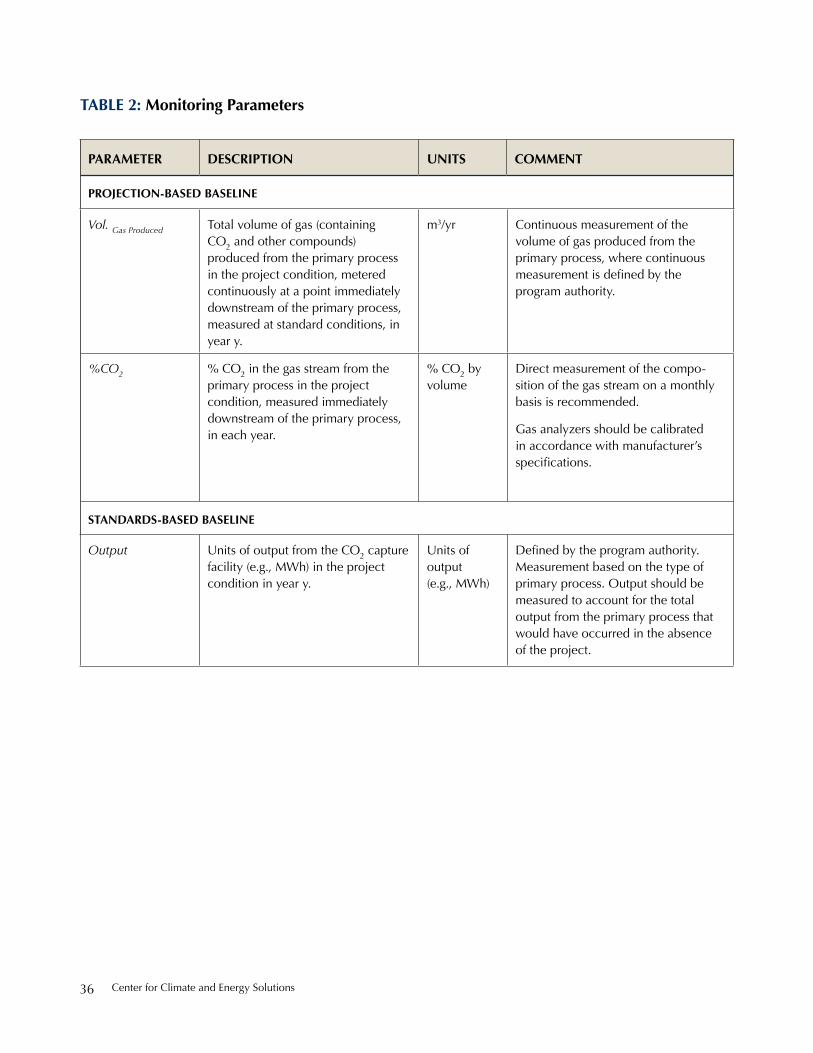
Center for Climate and energy solutions36
Vol. Gas Produced total volume of gas (containing Co2 and other compounds) produced from the primary process in the project condition, metered continuously at a point immediately downstream of the primary process, measured at standard conditions, in year y.
m3/yr Continuous measurement of the volume of gas produced from the primary process, where continuous measurement is defined by the program authority.
%CO2 % Co2 in the gas stream from the primary process in the project condition, measured immediately downstream of the primary process, in each year.
% Co2 by volume
direct measurement of the compo-sition of the gas stream on a monthly basis is recommended.
Gas analyzers should be calibrated in accordance with manufacturer’s specifications.
standards-based baseline
Output units of output from the Co2 capture facility (e.g., Mwh) in the project condition in year y.
units of output (e.g., Mwh)
Defined by the program authority. Measurement based on the type of primary process. output should be measured to account for the total output from the primary process that would have occurred in the absence of the project.
table 2: monitoring Parameters
Parameter desCriPtion units Comment
ProjeCtion-based baseline
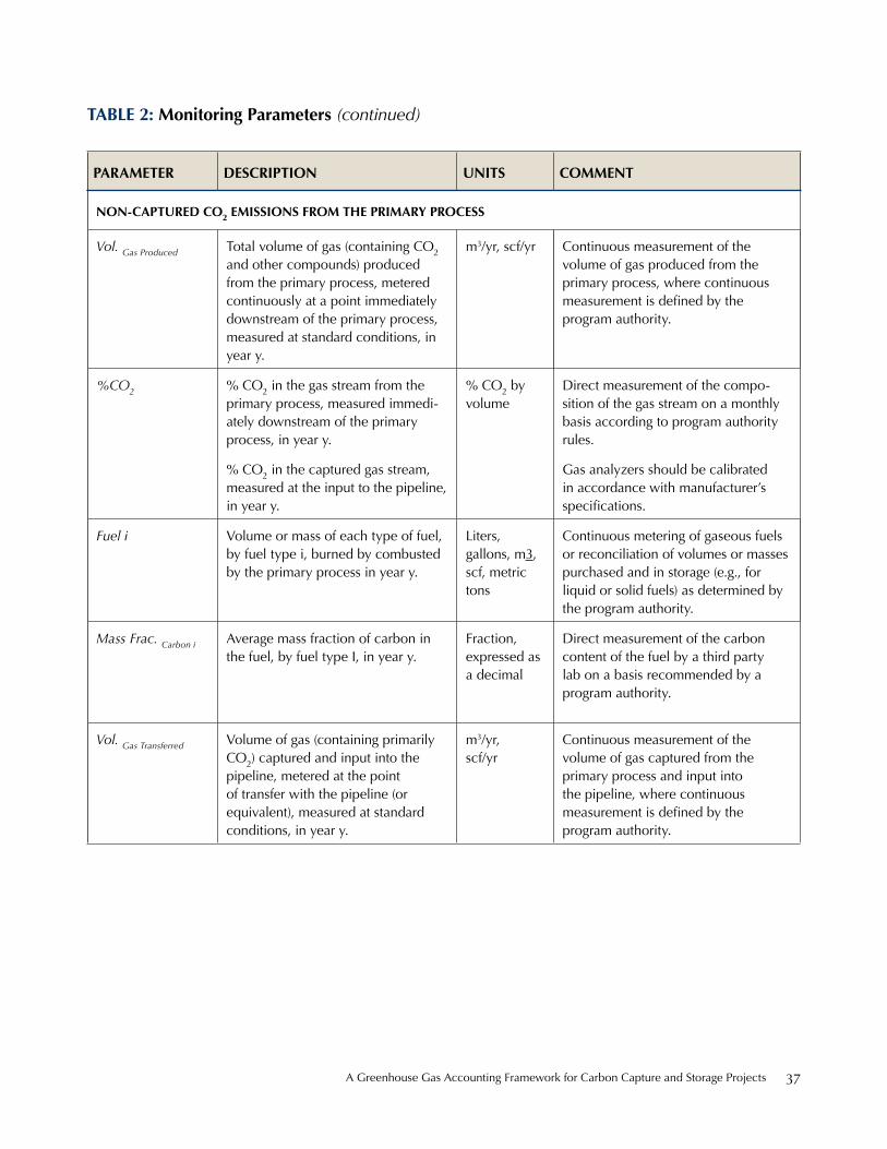
A Greenhouse Gas Accounting Framework for Carbon Capture and storage projects 37
non-CaPtured Co2 emissions From tHe Primary ProCess
Vol. Gas Produced total volume of gas (containing Co2 and other compounds) produced from the primary process, metered continuously at a point immediately downstream of the primary process, measured at standard conditions, in year y.
m3/yr, scf/yr Continuous measurement of the volume of gas produced from the primary process, where continuous measurement is defined by the program authority.
%CO2 % Co2 in the gas stream from the primary process, measured immedi-ately downstream of the primary process, in year y.
% Co2 in the captured gas stream, measured at the input to the pipeline, in year y.
% Co2 by volume
direct measurement of the compo-sition of the gas stream on a monthly basis according to program authority rules.
Gas analyzers should be calibrated in accordance with manufacturer’s specifications.
Fuel i Volume or mass of each type of fuel, by fuel type i, burned by combusted by the primary process in year y.
Liters, gallons, m3, scf, metric tons
Continuous metering of gaseous fuels or reconciliation of volumes or masses purchased and in storage (e.g., for liquid or solid fuels) as determined by the program authority.
Mass Frac. Carbon i Average mass fraction of carbon in the fuel, by fuel type i, in year y.
Fraction, expressed as a decimal
direct measurement of the carbon content of the fuel by a third party lab on a basis recommended by a program authority.
Vol. Gas Transferred Volume of gas (containing primarily Co2) captured and input into the pipeline, metered at the point of transfer with the pipeline (or equivalent), measured at standard conditions, in year y.
m3/yr, scf/yr
Continuous measurement of the volume of gas captured from the primary process and input into the pipeline, where continuous measurement is defined by the program authority.
Parameter desCriPtion units Comment
table 2: monitoring Parameters (continued)
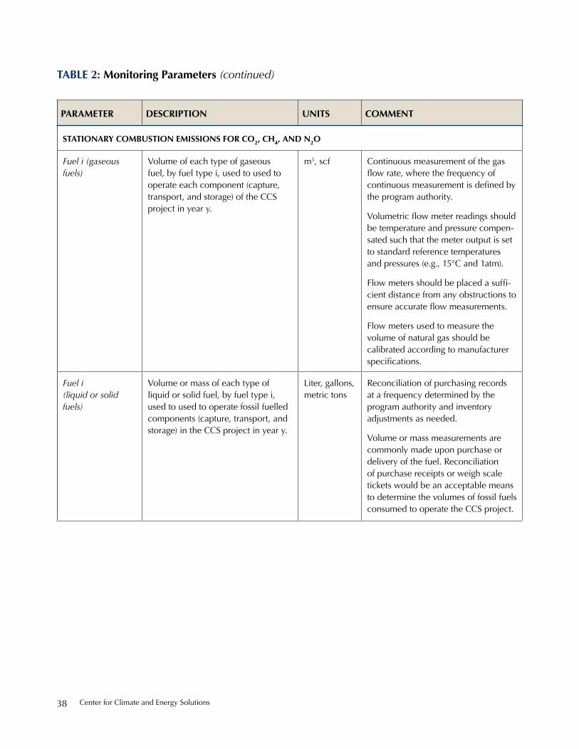
Center for Climate and energy solutions38
stationary Combustion emissions For Co2, CH4, and n2o
Fuel i (gaseous fuels)
Volume of each type of gaseous fuel, by fuel type i, used to used to operate each component (capture, transport, and storage) of the CCs project in year y.
m3, scf Continuous measurement of the gas flow rate, where the frequency of continuous measurement is defined by the program authority.
Volumetric flow meter readings should be temperature and pressure compen-sated such that the meter output is set to standard reference temperatures and pressures (e.g., 15°C and 1atm).
Flow meters should be placed a suffi-cient distance from any obstructions to ensure accurate flow measurements.
Flow meters used to measure the volume of natural gas should be calibrated according to manufacturer specifications.
Fuel i (liquid or solid fuels)
Volume or mass of each type of liquid or solid fuel, by fuel type i, used to used to operate fossil fuelled components (capture, transport, and storage) in the CCs project in year y.
Liter, gallons, metric tons
reconciliation of purchasing records at a frequency determined by the program authority and inventory adjustments as needed.
Volume or mass measurements are commonly made upon purchase or delivery of the fuel. reconciliation of purchase receipts or weigh scale tickets would be an acceptable means to determine the volumes of fossil fuels consumed to operate the CCs project.
Parameter desCriPtion units Comment
table 2: monitoring Parameters (continued)

A Greenhouse Gas Accounting Framework for Carbon Capture and storage projects 39
indireCt Co2 emissions From PurCHased and Consumed eleCtriCity, steam, Heat (iF reQuired by a Program autHority)
Electricity Metered electricity usage from equipment used to operate electrically driven component (capture, transport, and storage) in the CCs project in year y.
Mwh Continuous measurement of electricity consumption or reconciliation of maximum kw rating for each type of equipment and operating hours. electricity meters should be calibrated by an accredited party at a frequency determined by the program authority.
electricity consumption should be metered continuously wherever possible for the CCs project; however, in certain cases other loads may be tied into the same electricity meter and estimates may be required. in these cases the maximum kw rating of each piece of equipment could be used in conjunction with a conser-vative estimate of operating hours (e.g., 8760 hours per year) to estimate the electricity consumption.
Total Fuel Cogen
total volume or mass of each type of fuel, by fuel type i, combusted by the third party cogeneration unit supplying electricity or thermal energy to the Co2 capture and compression facilities in year y.
Liters, gallons, m3, scf, metric tons
Continuous metering of gaseous fuels or reconciliation of volumes or masses (e.g., for liquid or solid fuels) purchased and in storage at a frequency determined by the program authority.
Heat CCS Project Quantity of thermal energy purchased from the third party cogeneration unit to operate the Co2 capture facilities in year y.
Mwh Continuous metering of thermal energy sales/purchases to/for the CCs project using a utility meter. steam meters, or similar, should be calibrated by a program-authority-accredited party at a frequency determined by the program authority.
Electricity CCS Project
Quantity of electricity purchased from the third party cogeneration unit to operate the Co2 capture and compression facilities in year y.
Mwh Continuous measurement of electricity sales/purchases to/for the CCs project. electricity meters should be calibrated by program-authority-accredited party at a frequency determined by the program authority.
Parameter desCriPtion units Comment
table 2: monitoring Parameters (continued)
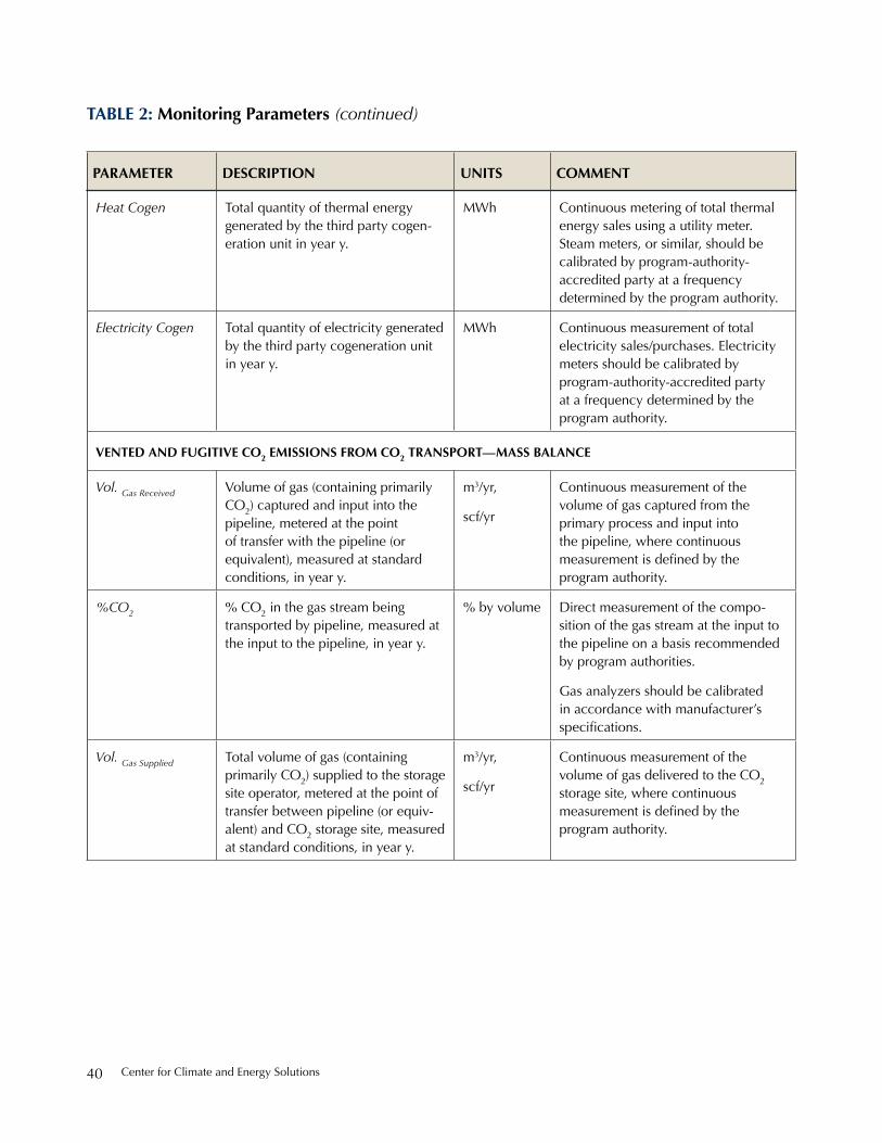
Center for Climate and energy solutions40
Heat Cogen total quantity of thermal energy generated by the third party cogen-eration unit in year y.
Mwh Continuous metering of total thermal energy sales using a utility meter. steam meters, or similar, should be calibrated by program-authority-accredited party at a frequency determined by the program authority.
Electricity Cogen total quantity of electricity generated by the third party cogeneration unit in year y.
Mwh Continuous measurement of total electricity sales/purchases. electricity meters should be calibrated by program-authority-accredited party at a frequency determined by the program authority.
vented and Fugitive Co2 emissions From Co2 transPort—mass balanCe
Vol. Gas Received Volume of gas (containing primarily Co2) captured and input into the pipeline, metered at the point of transfer with the pipeline (or equivalent), measured at standard conditions, in year y.
m3/yr,
scf/yr
Continuous measurement of the volume of gas captured from the primary process and input into the pipeline, where continuous measurement is defined by the program authority.
%CO2 % Co2 in the gas stream being transported by pipeline, measured at the input to the pipeline, in year y.
% by volume direct measurement of the compo-sition of the gas stream at the input to the pipeline on a basis recommended by program authorities.
Gas analyzers should be calibrated in accordance with manufacturer’s specifications.
Vol. Gas Supplied total volume of gas (containing primarily Co2) supplied to the storage site operator, metered at the point of transfer between pipeline (or equiv-alent) and Co2 storage site, measured at standard conditions, in year y.
m3/yr,
scf/yr
Continuous measurement of the volume of gas delivered to the Co2 storage site, where continuous measurement is defined by the program authority.
Parameter desCriPtion units Comment
table 2: monitoring Parameters (continued)
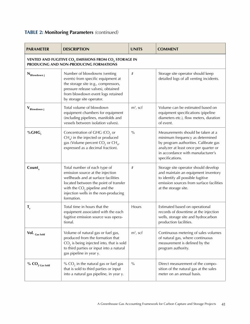
A Greenhouse Gas Accounting Framework for Carbon Capture and storage projects 41
vented and Fugitive Co2 emissions From Co2 storage in ProduCing and non-ProduCing Formations
nblowdown j number of blowdowns (venting events) from specific equipment at the storage site (e.g., compressors, pressure release valves), obtained from blowdown event logs retained by storage site operator.
# storage site operator should keep detailed logs of all venting incidents.
vblowdown j total volume of blowdown equipment chambers for equipment (including pipelines, manifolds and vessels between isolation valves).
m3, scf Volume can be estimated based on equipment specifications (pipeline diameters etc.), flow meters, duration of event.
%gHgi Concentration of GhG (Co2 or Ch4) in the injected or produced gas (Volume percent Co2 or Ch4, expressed as a decimal fraction).
% Measurements should be taken at a minimum frequency as determined by program authorities. Calibrate gas analyzer at least once per quarter or in accordance with manufacturer’s specifications.
Counts total number of each type of emission source at the injection wellheads and at surface facilities located between the point of transfer with the Co2 pipeline and the injection wells in the non-producing formation.
# storage site operator should develop and maintain an equipment inventory to identify all possible fugitive emission sources from surface facilities at the storage site.
ts total time in hours that the equipment associated with the each fugitive emission source was opera-tional.
hours estimated based on operational records of downtime at the injection wells, storage site and hydrocarbon production facilities.
vol. gas sold Volume of natural gas or fuel gas, produced from the formation that Co2 is being injected into, that is sold to third parties or input into a natural gas pipeline in year y.
m3, scf Continuous metering of sales volumes of natural gas, where continuous measurement is defined by the program authority.
% Co2 gas sold % Co2 in the natural gas or fuel gas that is sold to third parties or input into a natural gas pipeline, in year y.
% direct measurement of the compo-sition of the natural gas at the sales meter on an annual basis.
Parameter desCriPtion units Comment
table 2: monitoring Parameters (continued)

Center for Climate and energy solutions42
Mass Water Prod Mass of water produced from the formation that Co2 is being injected into, that is disposed of or otherwise not-re-injected back into the formation.
Metric tons Monthly reconciliation of water disposal records.
Mass Frac CO2 in
Water
Mass fraction of Co2 in the water produced from the formation.
- Conduct lab analysis of composition of produced water as required by the program authority.
Mass Hydrocarbons Prod Mass of crude oil and other hydro-carbons produced from the formation that Co2 is being injected into.
Metric tons reconciliation of hydrocarbon sales from facilities associated with the producing formation.
Mass Frac CO2 in Oil Mass fraction of Co2 in the crude oil and other hydrocarbons produced from the formation.
- Conduct lab analysis of composition of produced water as required by the program authority.
Co2 transFerred oFFsite in ProduCing reservoirs
Vol CO2_Transfer Volume of produced Co2 from an enhanced oil or gas operation transferred outside project boundary in each year.
m3, scf CCs projects developers deduct from quantified reductions “produced CO2” that is not reinjected but transferred offsite. Measured at a point to account for total volume not reinjected.
Fugitive Co2 From storage to atmosPHere in ProduCing and non-ProduCing Formations
CO2Z total mass of Co2 emitted through leakage pathway z to atmosphere in year y.
Metric tons in the event that leakage from the geologic reservoir to the atmosphere occurs, the mass of Co2 that has escaped would be estimated based on monitoring and measurements completed as part of the CCs project’s MrV plan.
note: examples of leakage pathways are faults and fractures, not fugitive Co2 from wells (as calculated according to equation 8.3.1).
Parameter desCriPtion units Comment
table 2: monitoring Parameters (continued)

A Greenhouse Gas Accounting Framework for Carbon Capture and storage projects 43
12. monitoring geologiC storage oF Co2
Monitoring CO2 storage operations provides the basis to substantiate assertions that injected CO2 remains permanently sequestered from the atmosphere. For CCS projects that seek recognition for GHG reductions a monitoring program for CO2 storage sites would, at a minimum, include components to validate that the risk of CO2 leakage from the geologic reservoir to the atmosphere is minimized, and, if a leak is detected, that corrective action measures are available to remediate occurrences of leakage. In the event that CO2 escapes from the geologic storage complex and results in emis-sions to the atmosphere, project developers would also quantify total emissions to the atmosphere according to Equation 9.
However, providing instructions to project developers on the type of monitoring systems to deploy to track injected CO2 in the subsurface is outside the scope of this document. Because of the complexity and unique-ness of each reservoir project developers would deter-mine the subsurface CO2 monitoring regime according to site-specific characteristics.
Therefore, this section provides a brief overview of monitoring activities that would occur during typical
stages of CO2 storage and a table of resource for devel-oping CO2 storage monitoring programs.
State and federal regulations cover all phases of CO2 injection and storage operations to protect human health and safety, property, and groundwater and other environmental resources. Additional aspects of a moni-toring program applicable to accounting for atmospheric emissions from the CO2 storage site would augment the requirements from state and federal agencies, in compli-ance with the appropriate program authority.
12.1 Overview of CO2 Storage Monitoring
Generally, project developers create CO2 storage site monitoring plans that include phases, such as (1) pre-operational monitoring, (2) operational monitoring, and (3) post-injection and closure monitoring.
The pre-operational monitoring phase forms the basis for the site selection process and supports the design of the monitoring plan for the operational phase, reflecting the assessed risks and baseline data. It consists of the following components:
• Site characterization
• Reservoir modeling
• Risk assessment
• Baseline monitoring
box 5: monitoring Co2 storage to assert Permanent Co2 sequestration under ePa’s uiC and gHgrP
A monitoring program for Co2 injection and storage operations—located at either non-producing formations or enhanced oil and gas recovery sites—that satisfies its respective Underground Injection Control (UIC) permit requirements and subpart rr of epA’s Greenhouse Gas reporting program (GhGrp) could provide the basis for a reasonable and sufficient assurance that CO2 is permanently stored.
enhanced oil and gas operators with Class ii permits may choose to report Co2 injection data to the epA under subpart uu—injection of Carbon dioxide—instead of subpart rr. if the Co2 storage component of a CCs project takes place at an enhanced oil and gas recovery operation, which does not have a monitoring, reporting and verification program consistent with Subpart RR, then project developers should create a monitoring regime that provides an equivalent level of confidence regarding the effectiveness of CO2 storage.
ultimately, all Co2 storage sites, including enhanced oil and gas recovery operations, have the responsibility to manage and monitor the facility in a manner consistent with the objective to permanently sequester injected Co2 from the atmosphere, regardless of its injection well class or whether it reports to the epA’s GhGrp under subpart rr or uu.
Appendix b provides an overview of the epA’s uiC and Greenhouse Gas reporting program.

Center for Climate and energy solutions44
The operational monitoring phase, for the purposes of accounting for emissions reductions from CCS projects, involves implementing systems to measure operational parameters, track the CO2 plume and monitor for leakage via the potential pathways identified in the pre-operational phase. In the event that leakage does occur during the operational phase, the project developer must estimate the quantity of CO2 that has leaked from the storage complex to the atmosphere in order to quantify the release, as incorporated in the quantification of the overall CCS project’s GHG emissions reduction (Sections 9.2.3 or 9.2.4).
CO2 storage site operators will implement a combination of surface and subsurface monitoring techniques to monitor parameters consistent with baseline information. Additionally, the program will include testing to confirm the mechanical integrity of the injection well(s). Operational monitoring would include the following components:
• Surface monitoring to detect and help quantify any leakage from pathways such as wells, faults and fractures that could result in a release to the atmo-sphere without prior detection in a lower monitoring zone, or to aid in the identification of suspected leaks based on monitoring in lower zones.
• Sub-surface monitoring to establish the behaviour of the CO2 plume in the subsurface, receive early warning about any possible migration along pathways to the surface, and inform any further monitoring or quantification action if needed.
• Mechanical integrity testing to establish confidence in the ability of wells to prevent unwanted fluid migration, and to trigger additional monitoring or quantification efforts if a leak is suspected.
The post-injection and closure monitoring phase is designed based on the information collected or modelled during the operational monitoring phase. It would consist of a monitoring phase immediately following the cessation of injection up to the point at which the site is closed, followed by a post-closure monitoring phase. The conditions for the site closure as well as the duration of the post-closure monitoring phase would be set out by the relevant program authority, consistent with the objective to ensure the permanent sequestration of injected CO2 from the atmosphere. Site closure should be based on site-specific and performance based measures.
Should CO2 leakage to the atmosphere from the geologic storage complex occur after injection has ceased, other mechanisms may be required to account for GHG emissions associated with CO2 leakage. It is expected that the program authority with oversight for the program or registration of emission reductions would provide additional guidance on how to address CO2 leaks and a reversal of GHG emissions reductions (e.g., a release of previously stored emissions). Potential mechanisms are discussed in Appendix A.
12.2 CO2 Storage Monitoring Best-Practice Manuals and Guidance Documents
The following table presents best-practice manuals and guidance documents to monitor geologic CO2 storage sites. Its purpose is to assist with development of CO2 monitoring strategies and programs; however, it is not a comprehensive list and project developers should continue to keep current on new resources.

A Greenhouse Gas Accounting Framework for Carbon Capture and storage projects 45
table 3: Co2 storage monitoring best-Practice manuals and guidance documents
1) U.S. Department of Energy, National Energy Technology Laboratory
“Best Practices for: Monitoring, Verification, and Accounting of CO2 stored in deep Geologic Formations” (2009)
www.netl.doe.gov/technologies/carbon_seq/refshelf/MVA_document.pdf
2) U.S. Environmental Protection Agency
“General technical support document for injection and Geologic sequestration of Carbon dioxide: subparts rr and uu Greenhouse Gas reporting program” (Chapter 4 & 5) (2010)
www.epa.gov/climatechange/emissions/downloads10/subpart-rr-uu_tsd.pdf
3) Lawrence Berkeley National Lab
“Geo-seQ best practices Manual: Geologic Carbon dioxide sequestration: site evaluation to implementation” (2004)
www.escholarship.org/uc/item/27k6d70j.pdf
4) Canadian Standards Association
“Geological storage of Carbon dioxide, CsA Z741” (in press)
www.csa.ca/cm/ca/en/standards/products/climate-change
5) European Commission
“Monitoring and reporting Guidelines for Greenhouse Gas emissions from the Capture, transport and Geological storage of Carbon dioxide” (2010)
ec.europa.eu/clima/documentation/ets/monitoring_monitoring_en.htm
6) European Commission
“Guidance document 2: Characterisation of the storage Complex, Co2 stream Composition, Monitoring and Corrective Measures” (2011)
ec.europa.eu/clima/policies/lowcarbon/docs/gd2_en.pdf
7) UK Department of Business Enterprise and Regulatory Reform
“Co2 Capture and storage in the eu emissions trading scheme—Monitoring and reporting Guidelines for inclusion Via Article 24 of the eu ets directive” (2007)
www.ieaghg.org/docs/General_docs/best%20practice%20docs/2007berr.pdf
8) International Energy Agency Greenhouse Gas R&D Programme
“interactive design of Monitoring programmes for the Geological storage of Co2” (2009)
www.ieaghg.org/co2tool_v2.2.2_product_joomla/index.php

Center for Climate and energy solutions46
9) International Energy Agency Greenhouse Gas R&D Programme
“overview of Monitoring techniques and protocols for Geologic storage projects” (2004)
www.co2captureandstorage.info/co2tool_v2.2.1/introduction.html
10) Intergovernmental Panel on Climate Change Guidelines for National Greenhouse Gas Inventories
“Chapter 5: Carbon dioxide transport, injection and Geological storage, Volume 2 – energy.” (2006)
www.ipcc-nggip.iges.or.jp/public/2006gl/index.html
11) British Geological Survey
“best practice for the storage of Co2 in saline Aquifers, observations and Guidelines from the sACs and Co2store projects” (2008)
www.bgs.ac.uk/downloads/start.cfm?id=1520
12) Det Norske Veritas
“CO2QUALSTORE: Guideline for Selection and Qualification of Sites and Projects for Geological Storage of Co2” (2010)
“Co2weLLs: Guideline for the risk Management of existing wells at Co2 Geological storage sites” (2011)
www.dnv.com/industry/energy/segments/carbon_capture_storage/recommended_practice_guidelines/co2qual-store_co2wells/index.asp
13) World Resources Institute
“CCs guidelines: Guidelines for Carbon dioxide Capture, transport, and storage” (2008)
www.wri.org/publication/ccs-guidelines
14) Co2 Capture project
“A technical basis for Carbon dioxide storage” (2009)
www.co2captureproject.org/allresults.php?pubcategory=storage
table 3: Co2 storage monitoring best-Practice manuals and guidance documents (continued)
A Greenhouse Gas Accounting Framework for Carbon Capture and storage projects 47
aPPendix a
additional gHg aCCounting-related issues For CCs ProjeCts
In addition to providing quantification methods to determine GHG reductions and presenting approaches to monitor CCS projects, program authorities with GHG reporting programs and registries will need to address policy-related issues in order to develop coherent systems and protocols to recognize GHG reductions from CCS projects. While there are number of specific issues that will need to be addressed in any GHG program that seeks to incentive GHG reductions (including eligibility requirements, roles and responsibilities of project participants, and third-party verification procedures), this appendix discusses four policy issues that pertain specifically to CCS projects and which could significantly impact CCS projects:
• Ownership of the CCS project’s GHG reductions;
• Additionality;
• Subsurface ownership of pore space into which the project developer will inject CO2; and
• Permanence and liability for reversals in GHG emis-sions reductions from CO2 storage sites.
Ultimately, the resolution of these issues will result from consultations between project developers, program administrators, and the public.
ownersHiP oF gHg reduCtions
For CCS projects with multiple entities involved in capturing, transporting, and storing CO2—with each potentially having separate legal responsibilities over the CO2, confusion over ownership of the emissions reduc-tions from the project could occur as control of the CO2 changes hands. This has significant importance if a CCS project developer seeks recognition for the emissions reductions from its projects, especially if CCS were to become an eligible project category for creating GHG offset credits.
While contractual negotiations will address many ownership claims, program authorities may want to
consider designating ownership of the CCS project’s GHG reductions to the entity that initially creates the CO2 (e.g., the owner of an electricity generating facility, if that is the source of CO2 for the CCS project). To the extent that capturing and sequestering CO2 has value, this would help clarify chain of custody negotiations between project participants. Such an approach would align with common practice that assigns responsibility for emissions reporting and control to the owner of the emissions source.
It is also useful to distinguish between ownership of a CCS project’s GHG reductions and responsibility under other regulatory programs for controlling and reporting CO2 emissions along the capture, transport, or injection and storage segments—e.g., the EPA’s Underground Injection Control and/or Greenhouse Gas Reporting Programs. For example, a company holding a Class II or VI permit has “corrective action” and liability obligations associated with the CO2 it injects into geologic reservoirs. Responsibility for the injected CO2, however, does not necessarily mean ownership of the emissions reductions from the CCS project. Project participants should clearly communicate through contractual arrangements owner-ship of the reductions.
additionality
In addition to providing rules regarding the ownership of a GHG emissions reduction, program administrators may also require an assessment of the additionality of a project. Additionality is concept that refers to whether the GHG reductions associated with the project would have occurred in the absence of a policy incentive that facili-tates the implementation of the project. It is often used as a project evaluation screen to assess if the emissions reductions from a project exceed business-as-usual. For instance, if the value of an offset credit is instrumental in bringing a GHG project to fruition, then it would likely be considered to pass the “additionality” test.
Conversely, if a project is implemented because it must comply with a law or regulation it is usually not

Center for Climate and energy solutions48
considered additional. In other words, the project would have happened without the value stream provided by the offset credit.
Additionality is an important concept because poli-cymakers do not aim to create incentive mechanisms to reward projects that would have happened even without the incentive. This is especially true with programs that allow GHG reductions from sources not covered by the program to be used as CO2 offset credits. In a GHG market-based program that allows offset credits, these credits could be traded and used by a different entity as if they had made the emission reduction themselves. As such, the offset credit must represent a reduction beyond what would have occurred “anyway,” or there is no real environmental benefit.
Determining a project’s additionality is an essential but approximate process and current offset programs utilize a variety of procedures and tests to determine the additionality of a project. A key component of addition-ality determinations is identifying a realistic baseline that forecasts emission levels in the project’s absence. Generally, two approaches are used to determine an appropriate baseline, which should result in a reasonable reference case against which to compare project emis-sions (and determine GHG reductions) as well as inform the additionality determination.
1. Project-specific. The project developer self-deter-mines the baseline, according to a method approved by a program authority.
The project-specific approach is often considered a bottoms-up method, in which individual project proponents have the responsibility to demonstrate that the approach to determine the baseline for their particular project is valid. Obtaining approval for a proposed “new methodology” under the Clean Development Mechanism (CDM) is an example of a project-specific approach to determine baselines.30
2. Programmatic. A program authority defines or approves a baseline for all types or a set of CCS projects that participate in its program and meet its eligibility requirements.
The programmatic approach follows a top-down method. In this case, the program authority sets the baseline for all CCS project, for example, within its jurisdiction. Examples of a programmatic approach to define baselines include performance standards—as in the protocols from the Climate Action Reserve31—and sector-level baselines.32
Project-Specific Baseline. Under the project-specific approach, the project proponent is responsible for executing a multi-step process to determine the baseline. The World Resources Institute (WRI) / World Business Council for Sustainable Development (WBCSD) GHG Protocol for Project Accounting (Project Protocol), provides a thorough description of the approach.
Broadly represented, the approach from WRI/WBCSD involves
• Identifying baseline candidates, which are alterna-tives to the proposed project that could feasibly be implemented in its place, given certain conditions; and
• Evaluating baseline candidates and the proposed project relative to barriers to implementation and determine the baseline scenario that applies to the project.
Barriers to implementing potential baseline candidates could include financial hurdles and/or technological challenges, for instance. Out of the field of baseline candidates, the project-specific approach should yield an identifiable baseline scenario—different from the proposed project– based on the relative impact of the barriers.33
In addition to the WRI/WBCSD Project Protocol, CDM includes a combined to tool to identify the baseline scenario demonstrate additionality.34
Programmatic Baseline. 35 Under the programmatic approach, relevant sector-level conditions and practices are evaluated to establish a standardized baseline and define additionality thresholds, usually applicable to multiple projects that meet specified applicability requirements (whereas the project-specific approach most often relates to a particular project).
A programmatic baseline is defined by a program authority, which could either approve a proposed program-wide baseline from a project proponent or create one itself. It could be expressed as an emission rate, a type of technology for the relevant sector, or common practice, among other ways.
An example of a top-down approach for setting programmatic baselines is the Regional Greenhouse Gas Initiative’s (RGGI) eligible offset categories. These include
• Landfill methane capture and destruction,
• Reduction in emissions of sulfur hexafluoride (SF6) in the electric power sector,

A Greenhouse Gas Accounting Framework for Carbon Capture and storage projects 49
• Sequestration of carbon due to afforestation,
• Reduction or avoidance of CO2 emissions from natural gas, oil, or propane end-use combustion due to end-use energy efficiency in the building sector, and
• Avoided methane emissions from agricultural manure management operations.36
Generally, programmatic baselines have broader applicability than project-specific baselines. A program that uses programmatic baseline, however, will be less flexible given that the predominant practices for the relevant sector are standardized and applied across the sector, regardless of the differences between projects.
Pore sPaCe ownersHiP
Another policy element that requires determination is the issue of subsurface pore space ownership. Resolving who owns the pore space into which the CO2 is injected is an area of significant interest that could potentially impact the liabilities associated with CO2 storage, should leakage to the atmosphere occur. In the U.S., property rights, including pore space ownership, are being addressed through state law and regulation. Indeed, several states have taken steps to settle pore space ownership issues by declaring that the surface owner has ownership rights to subsurface pore space.37
The Interstate Oil and Gas Compact Commission’s (IOGCC) “Legal and Regulatory Guide for States and Provinces” observes that injecting CO2 into various geologic formations for storage purposes, such as oil and gas reservoirs and saline formations, is governed by multiple surface and mineral interests. For example, mineral developers may be granted rights to extract resources under the terms of their mineral interests, while the ownership over geologic formations may be held by the party entitled to surface interests related to the land over the formation. IOGCC proposes designating the surface owner “with the right to lease pore space for storage, while protecting other stakeholders from potential damage attributable to sequestration activities.”38
In terms of GHG accounting, for CCS projects to safely and permanently sequester CO2 from the atmosphere CCS project developers must obtain rights to injection zone pore space prior to commencing CO2 injection. Furthermore, program authorities should also consider implementing rules that prevent changes in the use of pore space once it has been used for CO2 storage.
This might happen for example should there be a desire to convert CO2 storage into natural gas storage, which could displace CO2, and potentially cause a release to the atmosphere.
PermanenCe and liability For reversals in gHg emissions reduCtions
Program administrators may also require that CCS project developers demonstrate a level of assurance that the CO2 capture and stored is permanently sequestered underground. However, defining what constitutes “permanent” in a way that (1) provides confidence that the selection, management, and closure of CO2 storage sites will perform as an effective climate mitigation solu-tion, and (2) enables CO2 storage operators to practically demonstrate their storage complex meets the definition, is currently an unsettled issue.
Ultimately, identifying a threshold that signifies an acceptable minimum level of CO2 retention for geologic reservoirs—i.e., a CO2 storage standard, expressed as a retention rate—could help serve as a screen to select suit-able CO2 storage sites. It could also be used as the basis for defining what permanence means in terms of CCS project accounting and could help in the determination of rules around project liability.
Liability concerns for CCS projects mainly focus on CO2 storage issues and identifying responsible parties to manage containment risk for decades after CO2 injec-tion has ceased. In terms of GHG emissions accounting, liability over failure to permanently sequester injected CO2 means taking responsibility for leaks and reversals of GHG emissions reductions. All sequestration projects—including geologic and terrestrial—have the potential for reversals because the GHG reductions are not the result of avoiding the production of the GHG emissions (i.e., replacing coal-fired with wind-powered electricity). Instead, CCS prevents produced CO2 from entering the atmosphere by routing it through a capture, transport, and storage system. A GHG reversal in the CCS context would occur when a geologic storage complex fails to sufficiently contain injected CO2, allowing it to (eventu-ally) enter the atmosphere. It is important to point out, though, that properly selected, operated and closed, sites are generally expected to permanently contain injected CO2 and project monitoring should provide further assurance.
Liability, as it relates to CCS, can be expressed as responsibility for:

Center for Climate and energy solutions50
1. Damages to human health, environment and property, and
2. Reversals in claimed GHG emissions reductions due to failure to contain injected CO2.
In some jurisdictions, the transfer of liability may ultimately be conveyed from the injection site operator to the State with periodic monitoring required to ensure stability of the injected CO2 over a long-term period. If long-term liability over the CCS project is eventually transferred from the project operator to the state, the CCS operator may be required to make a financial contribution to the program authority. At a minimum, the financial contribution would likely cover the antici-pated cost of monitoring for a period until the risk of leakage is deemed minimal.
While the CCS Accounting Framework does not provide specific recommendations to ensure permanent CO2 storage or recommend mechanisms that address liability for reversals in GHG emissions reductions, it provides the following key considerations to help inform program authorities develop rules and procedures to address these matters.
• In the case of CCS, permanence is ultimately a function of (1) the capability of a geologic storage reservoir to accept and retain injected CO2, and (2) the actions of the CO2 storage site owner/operator regarding site selection, operation, and closure.
• The general expectation among experts in the CCS community is that CO2 injected into properly sited and managed reservoirs should remain permanently sequestered from the atmosphere, and if CO2 emissions do occur then the likelihood of leakage is highest during injection, and through wells and faults.39
• In the event that problems arise with the CO2 storage complex, technical solutions exist to imple-ment corrective action measures to mitigate certain situations that could lead to leaks to the atmosphere.
• The Intergovernmental Panel on Climate Change’s (IPCC) Special Report on Carbon Capture and Storage (SRCCS) states that properly selected and managed storage sites should likely retain at least 99 percent of injected CO2 over 1000 years.40
• While it is incorrect to interpret IPCC to conclude that a retention rate of 99 percent over 100 years represents a recommended “performance standard” to which all CO2 storage sites must meet on an on-going basis,41 it could be used as a “design
standard” and serve to screen candidate CO2 storage sites.
• Along with monitoring technologies to validate and update the modeled behaviour of injected CO2, corrective action procedures to mitigate potential escapes from the CO2 storage complex, and a mechanism to cover liabilities in the event of non-performance, a CO2 storage “design standard” could be used as a starting point to satisfy the permanence criterion—i.e., to substantiate claims that a CCS project has yielded permanent GHG emissions reductions.
• Within the U.S., in the absence of a federal standard for individual storage sites, states have developed their own. For example, Texas requires a reasonable expectation that at least 99 percent of the carbon dioxide sequestered will remain sequestered for at least 1,000 years.42 And the State of Washington defines permanence for CO2 sequestration as “the retention of greenhouse gases in a containment system… that creates a high degree of confidence that substantially ninety-nine percent of the greenhouse gases will remain contained for at least one thousand years.”43 Other states have also explored options to define a performance standard for CCS sites.44
• The permitting process for the EPA’s UIC program obligates storage site operators to sufficiently contain injected CO2 in a manner that prevents leaks from the storage complex, which could contaminate underground sources of drinking water.45
• The requirement to contain injected CO2 that underpins the UIC program and protects USDW is consistent with the prerequisite for CCS that injected CO2 remain permanently sequestered from the atmosphere.
• Policy options exist to address damages associ-ated with reversals in emissions reductions from CCS projects. Program authorities could use the following four options for managing the risk associ-ated with leaks from the CO2 storage formation to the atmosphere:
1. An assurance factor: A percentage of all tons credited are discounted according to a coef-ficient that takes into account the probability of a reversal occurring over a set period of time for a defined region. The discounted tons are handed over to the regulatory authority which holds them indefinitely.

A Greenhouse Gas Accounting Framework for Carbon Capture and storage projects 51
2. Holdbacks/Buffer Pools: A percentage of all tons credited are held in a reserve account. In the event of leakage, debit is measured and reported, verified, and reconciled by the account. The tons held in the reserve can be returned to the project operator through periodic review and recalibration of the size of the reserve.
3. Private insurance: The project developer purchases private insurance. Insurance premiums would be paid by the project devel-oper to the insurance company, and, in the event
of CO2 leakage to the atmosphere, the insurance company would cover obligations to compensate for reversals in GHG emissions reductions (e.g., purchase allowances or credits).
4. Bonding: The project developer posts a bond as assurance for performance. It would be acquired on an up-front basis and forfeited if CO2 leakage to the atmosphere occurs; bond proceeds would be used to cover obligations to compensate for reversals in emissions reductions.

Center for Climate and energy solutions52
aPPendix b
tHe u.s. ePa’s underground injeCtion Control and greenHouse gas rePorting Programs
The U.S. EPA’s Underground Injection Control (UIC) Program and Greenhouse Gas Reporting Program (GHGRP) include requirements relevant to accounting for GHG reductions associated with CCS projects.
1. tHe underground injeCtion Control Program
EPA’s UIC Program promulgated minimum Federal requirements for underground injection to ensure protection of underground sources of drinking water (USDWs) under the authority of the Safe Drinking Water Act. EPA distinguishes six injection well classes (Classes I through VI), depending on the type of fluid injected underground and the purpose of the activity.46 UIC Program implementation is conducted by either EPA or States that have applied for and received primary enforcement responsibility (primacy).47
Class VI and Class II requirements apply to CO2 injection for purposes of geologic sequestration and enhanced oil and gas recovery, respectively. Rules for Class VI wells include permitting, site characterization, area of review delineation, well construction and opera-tion, monitoring, well plugging, post-injection site care and site closure.48 Similarly, EPA provides minimum requirements for Class II operations, including rules for well construction, operating, monitoring, reporting, plugging, and closure.49 The intent of a Class II opera-tion is for enhanced oil and gas operations and not necessarily to permanently sequester injected CO2; if it meets specific conditions defined in EPA’s rules for Class VI wells it must transition from a Class II to a Class VI permit.50
Because Class VI wells are designed for projects that handle very large volumes of CO2 injected into relatively unfamiliar geologic formations (e.g., saline aquifers), EPA produced more demanding regulations than the Class II rules, which apply to well known and tested oil and gas fields. A UIC Class VI permit involves additional site characterization, computational modeling, well testing, project monitoring, and other requirements.
Both Class VI and Class II requirements are designed to contain injected CO2 within their respective storage formations, and permits issued from either the EPA or State agencies for both well classes obligate CO2 injec-tion facilities to operate their sites in a manner that will prevent CO2 (and other formation fluids) from migrating out of the geologic containment system into drinking water aquifers.51 Receipt of a UIC permit to commence CO2 injection means the site operator has demonstrated to the appropriate regulatory authority that it’s opera-tion should not result in CO2 escaping the containment complex and enter a drinking water aquifer.
While neither Class VI nor Class II requirements address accounting for emissions to the atmosphere, effec-tive containment to satisfy UIC permits should, for the vast majority of cases, result in CO2 sequestration from the atmosphere.52 Therefore, along with CO2 storage moni-toring (discussed below), Class II and Class VI permitting should support a GHG program-specific process to ensure that injected CO2 associated with CCS projects remains permanently sequestered from the atmosphere.
2. tHe greenHouse gas rePorting Program
The EPA’s GHGRP directly aligns with the objectives of the CCS Accounting Framework, as the purpose of the program is to provide a platform to account for and report GHG emissions from participating facilities.53 Several subparts of the GHGRP pertain to the CCS Accounting Framework, as CO2 capture would occur at facilities for which the GHGRP has industry-specific GHG accounting rules and procedures (e.g., power generation, Subpart D; hydrogen production, Subpart P; petroleum and natural gas systems, Subpart W).
However, the most relevant components of the GHGRP to GHG accounting for CCS projects are Subpart RR—Geologic Sequestration of Carbon Dioxide—and Subpart PP—Suppliers of Carbon Dioxide. Subpart RR applies to all CO2 sequestration sites, including wells permitted under Class VI as well as Class II sites that choose to classify their CO2 enhanced oil and gas injection operation as a CO2 sequestration activity.54 Subpart PP applies to suppliers of CO2. With respect to CCS projects, Subpart PP would affect companies that capture CO2 for the sake of geologic sequestration.55

A Greenhouse Gas Accounting Framework for Carbon Capture and storage projects 53
Project monitoring for CO2 injection and storage under Subpart RR to EPA’s GHG reporting program requires the development of a monitoring, reporting, and verification (MRV) plan that includes, at a minimum the following components:
• Delineation of monitoring areas,
• Identification and assessment of potential surface leakage pathways,
• Strategy for detecting and quantifying surface leakage of CO2 if leakage occurs,
• Approach for establishing the expected baselines, and
• Summary of considerations for calculating site-specific variables for the mass balance equation.56
CO2 storage monitoring under EPA’s GHGRP Subpart RR complements and builds on UIC permit requirements. Fulfilling the Class VI requirements can provide the basis for the MRV plan submitted to EPA for GHG reporting purposes under Subpart RR.57 A Class II well designated as a geologic sequestration activity would not necessarily have to change well class, but would augment its permitted MRV procedures for the UIC program to comply with requirements under EPA’s GHGRP Subpart RR.
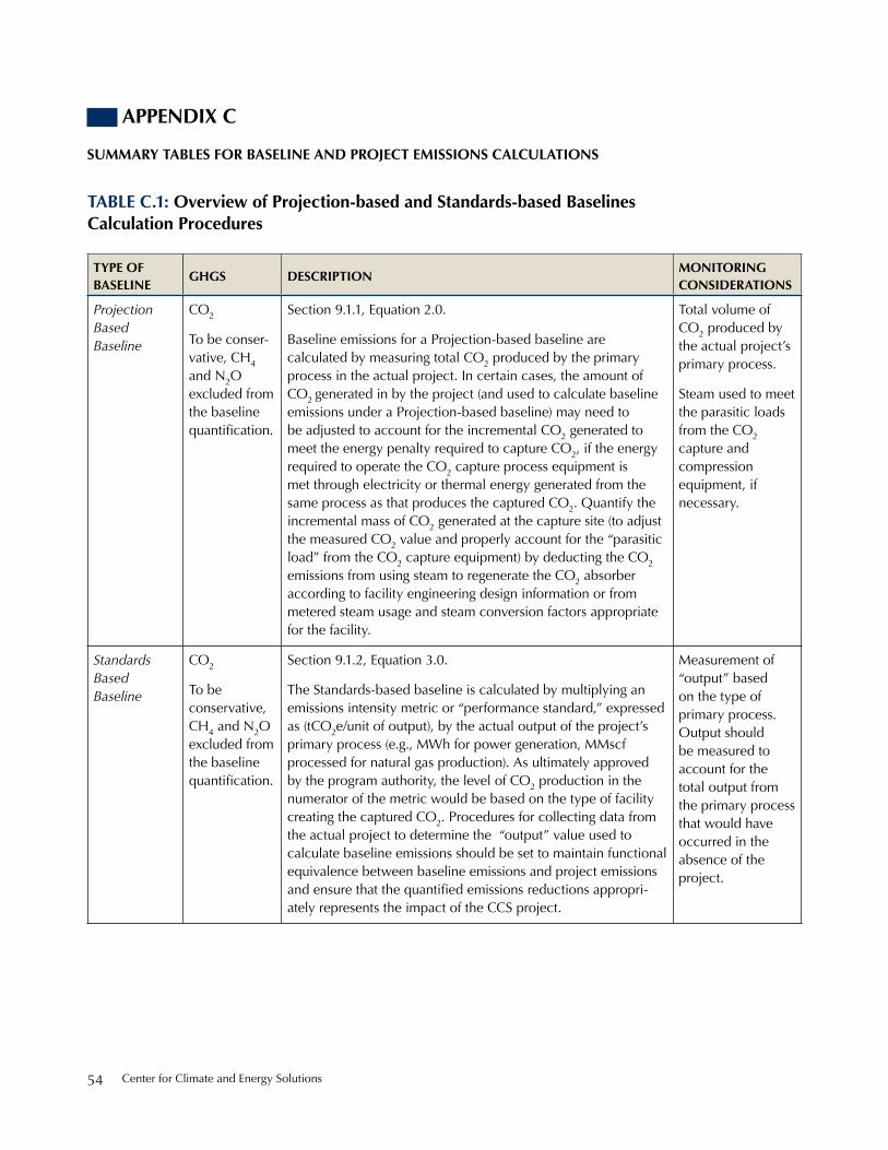
Center for Climate and energy solutions54
aPPendix C
summary tables For baseline and ProjeCt emissions CalCulations
table C.1: overview of Projection-based and standards-based baselines Calculation Procedures
tyPe oF baseline
gHgs desCriPtionmonitoring Considerations
Projection Based Baseline
Co2
to be conser-vative, Ch4 and n2o excluded from the baseline quantification.
section 9.1.1, equation 2.0.
baseline emissions for a projection-based baseline are calculated by measuring total Co2 produced by the primary process in the actual project. in certain cases, the amount of Co2 generated in by the project (and used to calculate baseline emissions under a projection-based baseline) may need to be adjusted to account for the incremental Co2 generated to meet the energy penalty required to capture Co2, if the energy required to operate the Co2 capture process equipment is met through electricity or thermal energy generated from the same process as that produces the captured Co2. Quantify the incremental mass of Co2 generated at the capture site (to adjust the measured Co2 value and properly account for the “parasitic load” from the Co2 capture equipment) by deducting the Co2 emissions from using steam to regenerate the Co2 absorber according to facility engineering design information or from metered steam usage and steam conversion factors appropriate for the facility.
total volume of Co2 produced by the actual project’s primary process.
steam used to meet the parasitic loads from the Co2 capture and compression equipment, if necessary.
Standards Based Baseline
Co2
to be conservative, Ch4 and n2o excluded from the baseline quantification.
section 9.1.2, equation 3.0.
the standards-based baseline is calculated by multiplying an emissions intensity metric or “performance standard,” expressed as (tCo2e/unit of output), by the actual output of the project’s primary process (e.g., Mwh for power generation, MMscf processed for natural gas production). As ultimately approved by the program authority, the level of Co2 production in the numerator of the metric would be based on the type of facility creating the captured Co2. procedures for collecting data from the actual project to determine the “output” value used to calculate baseline emissions should be set to maintain functional equivalence between baseline emissions and project emissions and ensure that the quantified emissions reductions appropri-ately represents the impact of the CCs project.
Measurement of “output” based on the type of primary process. output should be measured to account for the total output from the primary process that would have occurred in the absence of the project.

A Greenhouse Gas Accounting Framework for Carbon Capture and storage projects 55
table C.2: overview of Project Calculation Procedures
CCs segment
emission sourCes tyPe & gHgs
desCriPtionkey monitoring Parameters
CO2 Capture
total Capture emissions
Co2; Ch4; n2o
section 9.2.1, equation 5.0.
total project emissions from Co2 capture processes, including direct and indirect emissions.
n/A
non-captured Co2 from the primary process
Vented & Fugitive
Co2
section 9.2.1, equations 5.1; 5.1.A, 5.1.b, 5.1.C
Co2 emissions from the primary process, which has not been captured by the Co2 capture equipment and transferred to the transport (pipeline) segment. non-captured Co2 encapsulates Co2 emitted to the atmosphere from the capture site via vent stacks at the primary process and via venting or fugitive releases from other equipment at the capture and compression facilities. this quantity of Co2 is equal to the difference between the total quantity of Co2 produced and the quantity of Co2 input into the pipeline.
total volume of gas produced from the primary process, and captured and input into the pipeline
stationary Combustion
Co2; Ch4; n2o
section 9.2.1, equation 5.1.b & 5.2
A fuel-based calculation method, which applies to
1) primary process Ch4 and n2o emissions for projects that generate Co2 for capture through combustion, and
2) equipment used to capture and compress Co2, including cogeneration units, boilers, heaters, engines, turbines, flares, etc, which are owned and controlled by the capture site located at all capture sites.
Annual amount of fossil fuel burned, by fuel type
electricity and thermal energy use
(if required)
Co2; Ch4; n2o
section 9.2.1, equation 5.3, 5.3.A, 5.3.b, 5.3.C
indirect (scope 2) emissions from purchased and consumed electricity and thermal energy (steam) used to operate the Co2 capture and compression equipment. electricity may be used to operate the Co2 compressors, dehydration units, refrigeration units, circulation pumps, fans, air separation units and a variety of other equipment. purchased steam may be used for various purposes, including regeneration of the Co2-rich absorbent used for a post-combustion capture configuration.
total quantities of electricity and steam used to operate the Co2 capture equipment

Center for Climate and energy solutions56
table C.2: overview of Project Calculation Procedures
CCs segment
emission sourCes tyPe & gHgs
desCriPtionkey monitoring Parameters
CO2 Transport
total transport emissions
Co2; Ch4; n2o
section 9.2.2, equation 6.0.
total project emissions from Co2 transport, including vented, fugitive, stationary combustion, and purchased and consumed electricity.
n/A
stationary Combustion
Co2; Ch4; n2o
section 9.2.2, equation 6.1.
emissions from fossil fuel combustion to operate equipment used to transport Co2 to the storage site. For some projects, additional compression may be required along the pipeline or at an interconnection with a pipeline that is operated at a higher pressure. A variety of stationary combustion equipment may be used to inspect, maintain and operate the Co2 pipeline. stationary combustion equipment could include engines, turbines and heaters etc. that are under the direct control of the Co2 pipeline operator.
Annual amount of fossil fuel burned, by fuel type
Vented & Fugitive
Co2
section 9.2.2, equations 6.2; 6.2.A, 6.2.b
Vented and fugitive emissions are calculated according to a mass balance approach using metered values at the point of transfer at the capture site and at the storage site. Venting and fugitive releases during Co2 transportation. Fugitive emissions may arise from leakage of Co2 from equipment such as flanges, valves and flow meters. Emissions could also arise from compressor seal vents or pressure release valves. emissions could also be calculated according to an event-based approach for vented emissions and a component-count method for fugitive emissions. see Vented & Fugitive emissions for storage in non-producing reservoirs.
Metered quantities of Co2 input into the pipeline and delivered to storage site
electricity use
(if required)
Co2; Ch4; n2o
section 9.2.2, equation 6.3.
indirect emissions from electricity used to operate the Co2 transport infrastructure. In some CCS project configurations, electric-drive compressors may be used for supplemental compression along the Co2 pipeline, where grid connectivity exists.
Metered quantity of electricity used to operate the Co2 transport equipment
(continued)
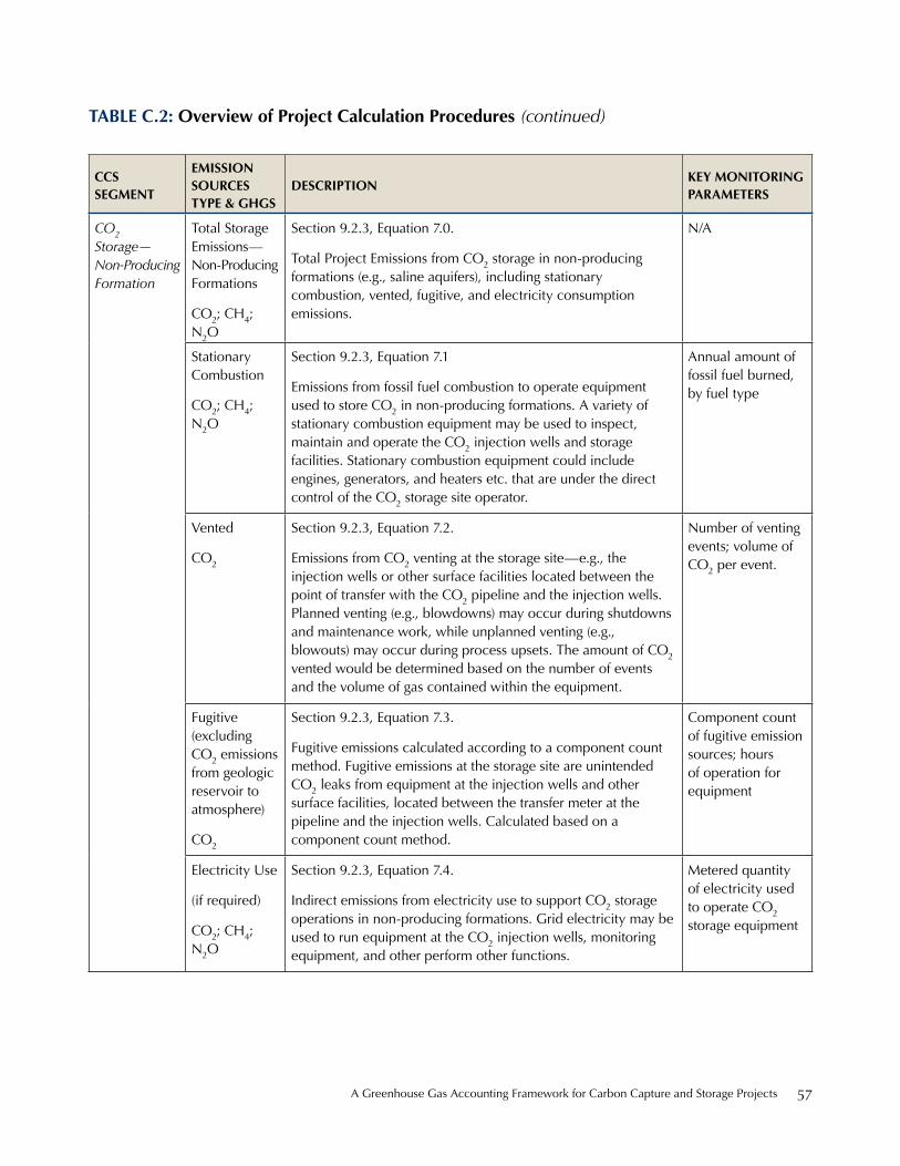
A Greenhouse Gas Accounting Framework for Carbon Capture and storage projects 57
table C.2: overview of Project Calculation Procedures
CCs segment
emission sourCes tyPe & gHgs
desCriPtionkey monitoring Parameters
CO2 Storage— Non-Producing Formation
total storage emissions— non-producing Formations
Co2; Ch4; n2o
section 9.2.3, equation 7.0.
total project emissions from Co2 storage in non-producing formations (e.g., saline aquifers), including stationary combustion, vented, fugitive, and electricity consumption emissions.
n/A
stationary Combustion
Co2; Ch4; n2o
section 9.2.3, equation 7.1
emissions from fossil fuel combustion to operate equipment used to store Co2 in non-producing formations. A variety of stationary combustion equipment may be used to inspect, maintain and operate the Co2 injection wells and storage facilities. stationary combustion equipment could include engines, generators, and heaters etc. that are under the direct control of the Co2 storage site operator.
Annual amount of fossil fuel burned, by fuel type
Vented
Co2
section 9.2.3, equation 7.2.
emissions from Co2 venting at the storage site—e.g., the injection wells or other surface facilities located between the point of transfer with the Co2 pipeline and the injection wells. planned venting (e.g., blowdowns) may occur during shutdowns and maintenance work, while unplanned venting (e.g., blowouts) may occur during process upsets. the amount of Co2 vented would be determined based on the number of events and the volume of gas contained within the equipment.
number of venting events; volume of Co2 per event.
Fugitive (excluding Co2 emissions from geologic reservoir to atmosphere)
Co2
section 9.2.3, equation 7.3.
Fugitive emissions calculated according to a component count method. Fugitive emissions at the storage site are unintended Co2 leaks from equipment at the injection wells and other surface facilities, located between the transfer meter at the pipeline and the injection wells. Calculated based on a component count method.
Component count of fugitive emission sources; hours of operation for equipment
electricity use
(if required)
Co2; Ch4; n2o
section 9.2.3, equation 7.4.
indirect emissions from electricity use to support Co2 storage operations in non-producing formations. Grid electricity may be used to run equipment at the Co2 injection wells, monitoring equipment, and other perform other functions.
Metered quantity of electricity used to operate Co2 storage equipment
(continued)

Center for Climate and energy solutions58
table C.2: overview of Project Calculation Procedures
CCs segment
emission sourCes tyPe & gHgs
desCriPtionkey monitoring Parameters
Co2 Storage— Producing Formation
total storage emissions— producing Formations
Co2; Ch4; n2o
section 9.2.4, equation 8.0
total project emissions from Co2 storage in producing forma-tions (e.g., enhanced oil and gas recovery), including stationary combustion, vented, fugitive, and electricity consumption emissions.
n/A
stationary Combustion
Co2; Ch4; n2o
section 9.2.4, equation 8.1.
emissions from fossil fuel combustion to operate equipment used to store Co2 in the producing formation. equipment could be used to operate, maintain or inspect the Co2 injection, storage, processing and recycling facilities and to operate the hydrocarbon production and processing facilities (e.g., gathering systems, oil-water-gas separators). emissions may occur from combustion of fossil fuels or combustion of hydrocarbons produced from the formation (e.g., in flares).
Annual amount of fossil fuel burned, by fuel type
Vented
Co2
section 9.2.4, equation 8.2
emissions from Co2 venting at the storage site—e.g., the injection wells or other surface facilities located between the point of transfer with the Co2 pipeline and the injection wells. Venting may also occur at the production wells, the hydro-carbon production and storage facilities or at the facilities used to process and recycle the produced Co2 for re-injection into the formation. planned venting may occur during shutdowns and maintenance work, while unplanned venting may occur during process upsets. the amount of Co2 vented would be determined based on the number of events and the volume of gas contained within the equipment.
number of venting events; volume of Co2 per event.
(continued)
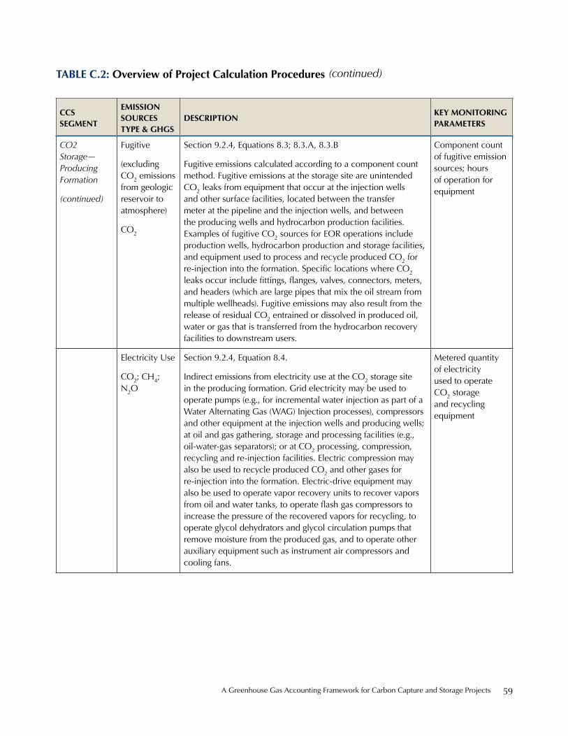
A Greenhouse Gas Accounting Framework for Carbon Capture and storage projects 59
table C.2: overview of Project Calculation Procedures
CCs segment
emission sourCes tyPe & gHgs
desCriPtionkey monitoring Parameters
CO2 Storage— Producing Formation
(continued)
Fugitive
(excluding Co2 emissions from geologic reservoir to atmosphere)
Co2
section 9.2.4, equations 8.3; 8.3.A, 8.3.b
Fugitive emissions calculated according to a component count method. Fugitive emissions at the storage site are unintended Co2 leaks from equipment that occur at the injection wells and other surface facilities, located between the transfer meter at the pipeline and the injection wells, and between the producing wells and hydrocarbon production facilities. examples of fugitive Co2 sources for eor operations include production wells, hydrocarbon production and storage facilities, and equipment used to process and recycle produced Co2 for re-injection into the formation. Specific locations where CO2 leaks occur include fittings, flanges, valves, connectors, meters, and headers (which are large pipes that mix the oil stream from multiple wellheads). Fugitive emissions may also result from the release of residual Co2 entrained or dissolved in produced oil, water or gas that is transferred from the hydrocarbon recovery facilities to downstream users.
Component count of fugitive emission sources; hours of operation for equipment
electricity use
Co2; Ch4; n2o
section 9.2.4, equation 8.4.
indirect emissions from electricity use at the Co2 storage site in the producing formation. Grid electricity may be used to operate pumps (e.g., for incremental water injection as part of a water Alternating Gas (wAG) injection processes), compressors and other equipment at the injection wells and producing wells; at oil and gas gathering, storage and processing facilities (e.g., oil-water-gas separators); or at Co2 processing, compression, recycling and re-injection facilities. electric compression may also be used to recycle produced Co2 and other gases for re-injection into the formation. electric-drive equipment may also be used to operate vapor recovery units to recover vapors from oil and water tanks, to operate flash gas compressors to increase the pressure of the recovered vapors for recycling, to operate glycol dehydrators and glycol circulation pumps that remove moisture from the produced gas, and to operate other auxiliary equipment such as instrument air compressors and cooling fans.
Metered quantity of electricity used to operate Co2 storage and recycling equipment
(continued)

Center for Climate and energy solutions60
table C.2: overview of Project Calculation Procedures
CCs segment
emission sourCes tyPe & gHgs
desCriPtionkey monitoring Parameters
CO2 Storage— Producing Formation
(continued)
transferred Co2
Co2
section 9.2.4, equation 8.5.
while not technically an emission, Co2 transferred outside the project boundary (i.e., produced-Co2 from an enhanced oil or gas recovery operation not re-injected but moved offsite) is deducted from claimed emissions reductions. if an enhanced oil and gas recovery site operator intends to move produced-Co2 between fields, then the boundary would encompasses the multiple fields employed (making sure to account for emissions from all relevant stationary combustion, vented, and fugitive emissions sources).
Volume of produced Co2 from an enhanced oil or gas operation transferred outside project boundary
CO2 Storage— Geologic Reservoir
Fugitive Co2 emissions from the geologic reservoir to the atmosphere
section 9.2.5, equation 9.
Applicable to Co2 storage at producing and non-producing reservoirs. For properly selected, operated, and closed Co2 storage operations, fugitive Co2 emissions from the geologic reservoir should happen only in extraordinary circumstances. emissions would be calculated on a site-by-site basis according to according to an approach approved by the program authority. For Co2 storage producing and non-producing storage facilities, the project monitoring plan would include a strategy for detecting and quantifying any surface Co2 leakage—i.e., leakage to atmosphere estimated based on monitoring and measurements completed as part of the MrV plan.
total mass of Co2 emitted through leakage pathways to atmosphere
(continued)
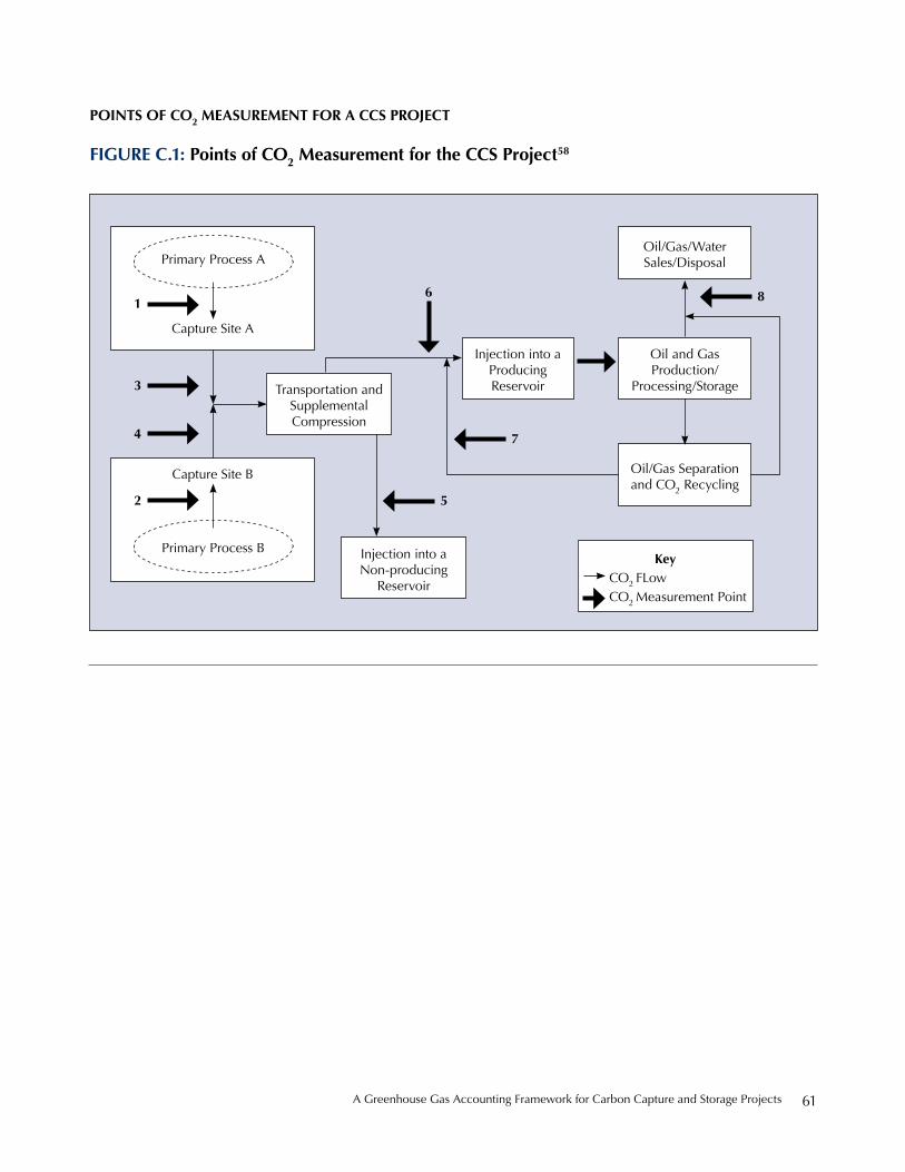
A Greenhouse Gas Accounting Framework for Carbon Capture and storage projects 61
Points oF Co2 measurement For a CCs ProjeCt
Figure C.1: Points of Co2 measurement for the CCs Project58
oil/Gas/water sales/disposal
oil and Gas production/
processing/storage
injection into a producing reservoirtransportation and
supplemental Compression
injection into a non-producing
reservoir
oil/Gas separation and Co2 recycling
primary process A
primary process b
Capture site A
Capture site b
keyCo2 FLowCo2 Measurement point
1
3
4
2 5
7
86
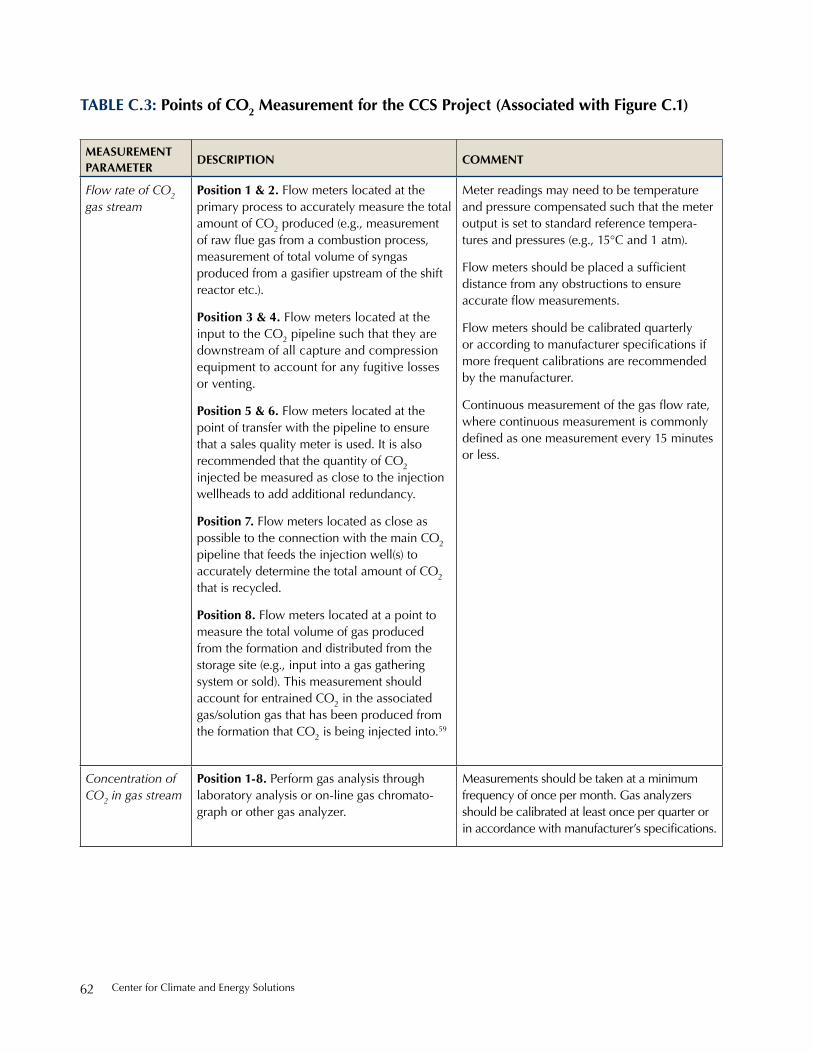
Center for Climate and energy solutions62
table C.3: Points of Co2 measurement for the CCs Project (associated with Figure C.1)
measurement Parameter
desCriPtion Comment
Flow rate of CO2 gas stream
Position 1 & 2. Flow meters located at the primary process to accurately measure the total amount of Co2 produced (e.g., measurement of raw flue gas from a combustion process, measurement of total volume of syngas produced from a gasifier upstream of the shift reactor etc.).
Position 3 & 4. Flow meters located at the input to the Co2 pipeline such that they are downstream of all capture and compression equipment to account for any fugitive losses or venting.
Position 5 & 6. Flow meters located at the point of transfer with the pipeline to ensure that a sales quality meter is used. it is also recommended that the quantity of Co2 injected be measured as close to the injection wellheads to add additional redundancy.
Position 7. Flow meters located as close as possible to the connection with the main Co2 pipeline that feeds the injection well(s) to accurately determine the total amount of Co2 that is recycled.
Position 8. Flow meters located at a point to measure the total volume of gas produced from the formation and distributed from the storage site (e.g., input into a gas gathering system or sold). this measurement should account for entrained Co2 in the associated gas/solution gas that has been produced from the formation that Co2 is being injected into.59
Meter readings may need to be temperature and pressure compensated such that the meter output is set to standard reference tempera-tures and pressures (e.g., 15°C and 1 atm).
Flow meters should be placed a sufficient distance from any obstructions to ensure accurate flow measurements.
Flow meters should be calibrated quarterly or according to manufacturer specifications if more frequent calibrations are recommended by the manufacturer.
Continuous measurement of the gas flow rate, where continuous measurement is commonly defined as one measurement every 15 minutes or less.
Concentration of CO2 in gas stream
Position 1-8. perform gas analysis through laboratory analysis or on-line gas chromato-graph or other gas analyzer.
Measurements should be taken at a minimum frequency of once per month. Gas analyzers should be calibrated at least once per quarter or in accordance with manufacturer’s specifications.
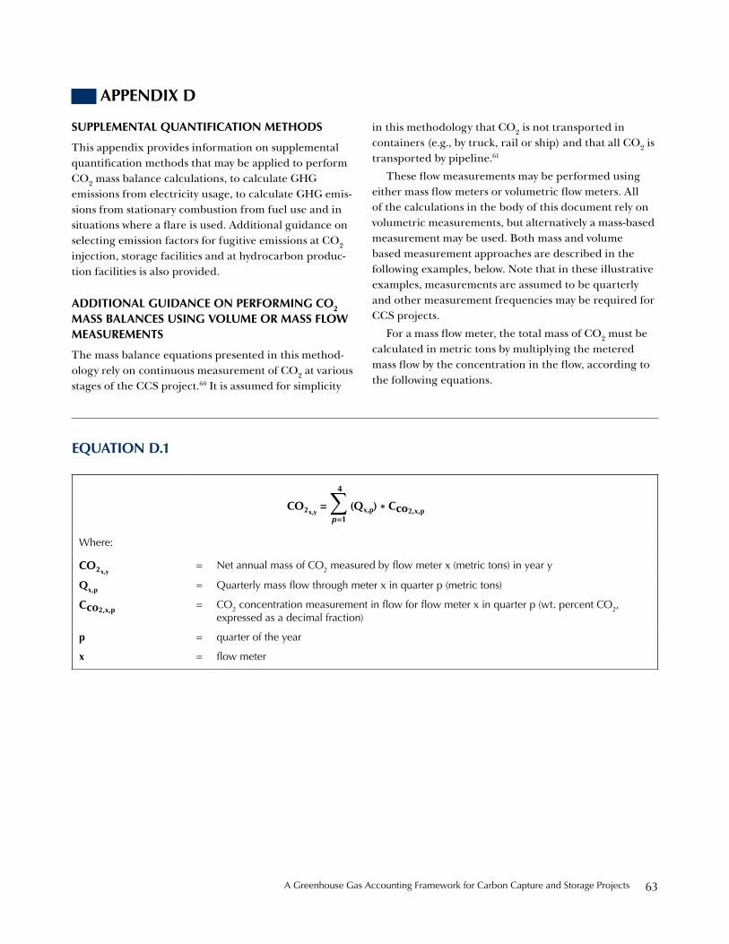
A Greenhouse Gas Accounting Framework for Carbon Capture and storage projects 63
aPPendix d
suPPlemental QuantiFiCation metHods
This appendix provides information on supplemental quantification methods that may be applied to perform CO2 mass balance calculations, to calculate GHG emissions from electricity usage, to calculate GHG emis-sions from stationary combustion from fuel use and in situations where a flare is used. Additional guidance on selecting emission factors for fugitive emissions at CO2 injection, storage facilities and at hydrocarbon produc-tion facilities is also provided.
additional guidanCe on PerForming Co2 mass balanCes using volume or mass Flow measurements
The mass balance equations presented in this method-ology rely on continuous measurement of CO2 at various stages of the CCS project.60 It is assumed for simplicity
in this methodology that CO2 is not transported in containers (e.g., by truck, rail or ship) and that all CO2 is transported by pipeline.61
These flow measurements may be performed using either mass flow meters or volumetric flow meters. All of the calculations in the body of this document rely on volumetric measurements, but alternatively a mass-based measurement may be used. Both mass and volume based measurement approaches are described in the following examples, below. Note that in these illustrative examples, measurements are assumed to be quarterly and other measurement frequencies may be required for CCS projects.
For a mass flow meter, the total mass of CO2 must be calculated in metric tons by multiplying the metered mass flow by the concentration in the flow, according to the following equations.
eQuation d.1
where:
Co2x,y= net annual mass of Co2 measured by flow meter x (metric tons) in year y
Qx,p = Quarterly mass flow through meter x in quarter p (metric tons)
Cco2,x,p = Co2 concentration measurement in flow for flow meter x in quarter p (wt. percent CO2, expressed as a decimal fraction)
p = quarter of the year
x = flow meter
Co2x,y = ∑ (Qx,p) * Cco2,x,p
4
p=1

Center for Climate and energy solutions64
For a volumetric flow meter, the total mass of CO2 is calculated in metric tons by multiplying the metered volumetric flow at standard conditions by the CO2 concentration in the flow, according to the formula below.
To apply the equation below, all measured volumes are converted to the following standard industry temperature and pressure conditions for use in the equation below: standard cubic meters at a temperature of 60 degrees Fahrenheit and at an absolute pressure of 1 atmosphere.
eQuation d.2
where:
Co2x,y= net annual mass of Co2 measured by flow meter x (metric tons) in year y
Qx,p = Quarterly volumetric flow through meter x in quarter p at standard conditions (standard cubic meters)
d = density of Co2 at standard conditions (metric tons per standard cubic meter)
Cco2,x,p = Co2 concentration measurement in flow for flow meter x in quarter p (vol. percent CO2, expressed as a decimal fraction)
p = quarter of the year
x = flow meter
When CO2 is measured using more than one meter within the same component of the CCS project (e.g., multiple CO2 injection wells), it may be necessary to sum
the meter readings to calculate an aggregate mass of CO2, as shown in the following equation.
eQuation d.3
where:
Co2y = total mass of Co2 measured by all flow meters in year y (metric tons)
Co2x,y= total mass of Co2 measured by flow meter x, as calculated in Equation D.1 or Equation D.2
in year y (metric tons)
x = flow meter
Co2x,y = ∑ (Qx,p) * d * Cco2,x,p
4
p=1
Co2y = ∑ Co2x,y
X
x=1

A Greenhouse Gas Accounting Framework for Carbon Capture and storage projects 65
additional metHod For CalCulating emissions From eleCtriCity use
The following equation can be used to quantify GHG emissions from the use of grid electricity at any
component of a CCS project as a contingency if a distinct electricity meter reading is unavailable (e.g., other loads that are unrelated to the CCS project are tied into the same meter).
eQuation d.4
Pe elec, y = ∑ (Electrical Rating i x Hours i x load i) x eF electricity
where,
Pe s-P-elec, y = project emissions from electricity used to operate equipment at the Co2 storage site in the producing formation in year y (tCo2e/yr).
electrical rating i = electrical rating in Mw for each piece of equipment used to operate equipment associated with the relevant component (e.g., capture, transport or storage) of the CCs project (Mw).
Hours i = operating hours for each piece of equipment (hours). estimated or assumed to be 8760 hours for conservativeness.
load i = % Loading of each piece of equipment (unitless). estimated or assumed to be 100%.
eF electricity = emission factor for electricity generation in the relevant region (tCo2e/Mwh).
additional metHod For CalCulating stationary Combustion emissions From tHe Primary ProCess based on Fuel use
The following equation can be used to quantify GHG emissions from stationary combustion from the primary
process at the capture site. It can be used for projects where directly measuring the volume (or mass) of CO2 produced at the primary process is not possible.
eQuation d.5
Co2 Produced PP, y = ∑(Fuel i x mass Frac Carbon, i x 44/12)
where,
Co2 Produced PP, y = Gross amount of Co2 produced from the primary process in each year (tCo2/yr).
Fuel i = total volume or mass of fuel, by fuel type i, input into the primary process in year each (e.g., m3 or kg).
mass Frac Carbon, i = Average mass fraction of carbon in fuel type i, (fraction expressed as a decimal).
44/12 = Conversion factor to convert from mass of carbon to mass of carbon dioxide using molecular weights (unitless).

Center for Climate and energy solutions66
additional metHod For CalCulating stationary Combustion emissions From Flaring
The following equation can be used to quantify GHG emissions from stationary combustion at the storage site
in the producing formation in situations where a flare is used to combust gases produced from the formation (e.g., gases that may contain CO2 that originates from the capture site).
eQuation d.6
Pe Flaring, y = ∑(Gas Flared i *∑(C i * y i)*44.01/23.64) + ∑(Flare Fuel i * eF Co2 Flare Fuel i) + ∑[ Gas Flared i * (1-de) * %CH4* r CH4)* gwP CH4 + ∑( Flare Fuel i * %CH4 * r CH4 * (1 - de))]*
gwP CH4 + ∑(Vol. gas Flared * eF n2o gas Flared i) + (Flare Fuel i * eF n2o Flare Fuel i)]* gwP n2o
where,
Pe Flaring, y = Project emissions from flaring of gases at hydrocarbon production facilities in year y (tCo2e/yr). Only applicable to facilities that flare gases that may contain CO2 originating from the producing formation.
gas Flared i = Volume of gas flared at hydrocarbon production facilities at the storage site in the producing formation in year y (m3/year).
Flare Fuel i = Volume of each supplemental fuel, by fuel type i, used to ensure complete combustion of gases from the producing formation in year y (m3/year).
C i = number of carbon atoms would be assessed based on the chemical formula of each gas (e.g., 1 for Ch4, 1 for Co2, 2 for C2h6)
y i = direct measurement of the mole fractions of each carbon-containing gas in the gas mixture.
44.01 = reference value for Molecular weight of Co2 (grams per mole).
23.64 = Volume occupied by 1 mole of an ideal gas at standard conditions of 15°C and 1 atmosphere.
de = Destruction efficiency of the flare (unitless).
%CH4 = Concentration of Ch4 in the gas stream that is being flared in year y (volume percent CO2 or Ch4, expressed as a decimal fraction).
r CH4= density of Co2 at standard conditions (metric ton/ m3).
eF n2o gas Flared i = n2O emission factor for flaring of gas stream originating from the producing formation (e.g., tn2o/m3).
eF Co2 Flare Fuel i = Co2 emission factor for combustion of each supplemental fuel, by fuel type i, used to ensure complete combustion of gases from the producing formation (e.g., tCo2/m
3).
eF n2o Flare Fuel i = n2o emission factor for combustion of each supplemental fuel, by fuel type i, used to ensure complete combustion of gases from the producing formation (e.g., tn2o/m3).
gwP CH4 = Global warming potential of methane = 21.
gwP n2o = Global warming potential of n2o = 310.
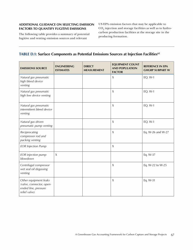
A Greenhouse Gas Accounting Framework for Carbon Capture and storage projects 67
additional guidanCe on seleCting emission FaCtors to QuantiFy Fugitive emissions
The following table provides a summary of potential fugitive and venting emission sources and relevant
US EPA emission factors that may be applicable to CO2 injection and storage facilities as well as to hydro-carbon production facilities at the storage site in the producing formation.
table d.1: surface Components as Potential emissions sources at injection Facilities62
emissions sourCeengineering estimates
direCt measurement
eQuiPment Count and PoPulation FaCtor
reFerenCe in ePa gHgrP subPart w
Natural gas pneumatic high bleed device venting
X eQ. w-1
Natural gas pneumatic high low device venting
X eQ. w-1
Natural gas pneumatic intermittent bleed device venting
X eQ. w-1
Natural gas driven pneumatic pump venting
X eQ. w-1
Reciprocating compressor rod and packing venting
X eq. w-26 and w-27
EOR Injection Pump X
EOR injection pump blowdown
X eq. w-37
Centrifugal compressor wet seal oil degassing venting
X eq. w-22 to w-25
Other equipment leaks (valve, connector, open-ended line, pressure relief valve)
X eq. w-31

Center for Climate and energy solutions68
A Greenhouse Gas Accounting Framework for Carbon Capture and storage projects 69
endnotes
1 Since accounting for indirect emissions inherently double-counts direct emissions, program authorities will decide if it is appropriate to include indirect emissions in its program.
2 EPA’s Greenhouse Gas Reporting Program requires the annual reporting of GHG data and other relevant infor-mation from facilities that emit 25,000 metric tons or more per year of GHGs. The reporting rules also apply to facilities that supply certain products that would result in GHG emissions if released, combusted or oxidized and facilities that inject CO2 underground for geologic sequestration or any purpose other than geologic sequestration. The rule has 47 subparts and can be found at www.epa.gov/climatechange/emissions/ghgrulemaking.html
3 Program authorities may need to supplement EPA’s Subpart RR MRV procedures with requirements of their own to fulfill program-specific needs.
4 ISO 14064-2 is consistent with the voluntary offset programs operated by the Climate Action Reserve (CAR), the America Climate Registry (ACR), and the Verified Carbon Standard (VCR), as well as the compliance program oper-ated by the Province of Alberta and the offset protocols accepted by the California Air Resources Board and the Clean Development Mechanism (CDM).
5 California Health and Safety Code, §38562(d)(1). Other GHG offset programs—e.g., CAR, ACR, VCS, Alberta Offset System—also require that offset projects be consistent with the project accounting criteria. Each program authority develops it own rules for satisfying the criteria.
6 The process to define a baseline is often a part of an “additionality” assessment. The CCS Accounting Framework, however, decouples baselines from additionality and discusses baseline options for the purpose of calculating the difference between the baseline and project emissions.
7 Generally, this document does not define a “deminimis” emissions threshold, which would affect whether project developers calculate emissions from small sources. Program authorities would create rules to determine the minimum level of emissions to account for and report to their respective programs and/or specify the types of emissions sources to exclude from the GHG reduction assessment.
8 This variable is included to maintain functional equivalence between the baseline and project.
9 The CCS Accounting Framework does not include calculation procedures to determine mobile source emissions, as it is generally recognized that a change in mobile emissions would not impact the calculated reductions from the project. The document also does not include procedures to determine one-time emissions productions from project construction.
10 For gasification projects, the total mass of CO2 produced would be determined based on the mass or volume and carbon content of the syngas produced from the gasifier, measured at a point upstream of the water-gas shift reactor and subsequent hydrogen purification steps. Note that carbon contained in char, slag or ash produced during gasification would not be included in the total amount of produced CO2.
11 The CO2 capture unit may only require a portion of the total electricity and/or heat output from the cogenera-tion unit so it might be necessary to account for the fraction of emissions from the cogeneration unit that are attributable to the CCS project.

Center for Climate and energy solutions70
12 For CO2 transported in containers, quantification guidance can be found EPA Subpart RR, 40 CFR § 98.443.
13 This approach follows the methods outlined in EPA Subpart PP-Suppliers of Carbon Dioxide. 40 CFR § 98.423, Equation PP-3b.
14 Composition of gas delivered to storage site is assumed to be same composition as the gas at inlet to the pipeline.
15 If permitted by a program authority, project developers could derive a CO2 pipeline emission factors based on natural gas transmission factors and then convert from methane to CO2 (emissions CO2/kilometer of pipeline). The American Petroleum Institute’s Compendium of Greenhouse Gas Emissions Methodologies for the Oil and Gas Industry (2004) is one source for a pipeline emissions factor.
16 This approach is consistent with the EPA’s GHGRP, as explained in its “General Technical Support Document for Injection and Geologic Sequestration of Carbon Dioxide: Subparts RR and UU.” Greenhouse Gas Reporting Program. November 2010. www.epa.gov/climatechange/emissions/subpart/rr.html.
17 Appendix D provides a summary of potential fugitive emission sources and resources for emission factors that may be applicable to CO2 injection and storage facilities.
18 See, for example, the National Institute of Standards and Technology database of thermodynamic properties using the Span and Wagner Equation of State. http://www.nist.gov/data/PDFfiles/jpcrd516.pdf
19 Appendix D provides a procedure for calculate emissions from combusting hydrocarbons produced at the forma-tion (e.g., in flares).
20 For CO2 Injection pump blowdowns it may be necessary to use the density of CO2 at supercritical conditions, which can be obtained from the National Institute of Standards and Technology (NIST) Database of thermodynamic properties using the Span and Wagner Equation of State.
21 For a discussion of detection thresholds, see Benson, S. (2006). Monitoring Carbon Dioxide Sequestration in Deep Geological Formations for Inventory Verification and Carbon Credits. Richardson, TX: Society of Petroleum Engineers.
22 Note: fugitive emissions from injection wells could be calculated according to Equation 7.3, as an emission factor is provided in EPA’s GHGRP, see Appendix D.
23 Project monitoring—and especially monitoring the geologic storage of CO2—is referred to in multiple ways, including “monitoring, verification, and accounting,” “monitoring, reporting, and verification, “monitoring, measurement, and verification,” among others. The CCS Accounting Framework uses term “project monitoring” to refer to the suite of activities to measure, collect, and organize data across the full value chain of a CCS project to assess project performance.
24 Monitoring CO2 capture facilities, pipelines, and storage sites to maintain compliance with local, state, and federal environmental health and safety requirements is outside the scope of this GHG accounting methodology.
25 The process to address CO2 leakage from the geologic storage reservoir is presented in Sections 9.2.3 and 9.2.4.
26 40 CFR §98.448(a). A monitoring plan for Subpart RR to EPA’s GHGRP would also include well classification information, and data collection timing information, among other things.
27 “Maximum monitoring area” and “active monitoring area” are defined terms in the EPA GHGRP—40 CFR §98.449.
28 See EPA’s GHGRP website: http://www.epa.gov/climatechange/emissions/ghgrulemaking.html.
29 CO2 pipelines do not have an obligation to report GHG emissions data to EPA; the monitoring procedures to determine GHG emissions from CO2 transport in this document follow common practice procedures.
30 For a thorough review of additionality and the clean development mechanism please see Pew’s white paper on the Clean Development Mechanism, a Review of the First International Offset Mechanism, March, 2011.
A Greenhouse Gas Accounting Framework for Carbon Capture and storage projects 71
31 http://www.climateactionreserve.org/how/protocols/.
32 See, for example, provisions for sector-level crediting under the California Air Resources Board’s Cap and Trade Regulation Order (§ 95991-95997) available at: http://www.arb.ca.gov/regact/2010/capandtrade10/capandtrade10.htm.
33 The baseline candidate least affected by the barriers to implementation usually represents the baseline scenario. It is possible that the proposed project could be the option least affected by the barriers—making it the same as the baseline. However, given the nature of CCS projects and the limited number of U.S. programs to control or price CO2 emissions, this would likely be exceptional.
34 http://cdm.unfccc.int/Reference/tools/index.html.
35 A programmatic baseline could also be referred to as “performance standard” or “multi-project.” The distinction between these similar terms mainly concerns “additionality” issues.
36 Additional information on the Regional Greenhouse Gas Initiative is available at http://www.rggi.org/home.
37 For a review of state-level activities, see CO2 Capture Project, 2010, Section 5. http://www.co2captureproject.org/.
38 IOGCC, 2007.
39 Benson, 2006.
40 IPCC, 2005.
41 Benson, 2006.
42 Texas Tax Code: SECTION 9, Subchapter B, Sec.202.0545 (d)(1).
43 State of Washington 2008. WAC §§ 173-218-115(4)(a)(i)(A). Definitions.
44 See, for example, California’s Carbon Capture and Storage Review Panel Recommendations, 2010; CA CCS Review Panel Recommendations, 2010.
45 40 CFR §144.12.
46 http://water.epa.gov/type/groundwater/uic/.
47 For information about program implementation in specific States, Tribes, or Territories, see http://www.epa.gov/ogwdw/uic/pdfs/Delegation%20status.pdf.
48 http://water.epa.gov/type/groundwater/uic/class6/gsregulations.cfm
49 40 CFR Part 144 and Subpart-C of Part 146.
50 40 CFR, §144.19.
51 40 CFR §144.12.
52 Conceivably, CO2 could migrate out of a CO2 storage complex without contaminating an underground source of drinking water and leak to the atmosphere through the injection well or a transmissive fault that bypasses the aquifer, for instance.
53 EPA’s Greenhouse Gas Reporting Program requires select direct GHG emitters, fossil fuel and industrial gas suppliers, manufacturers of vehicles and engines, and injectors of CO2 to annually account for and report emissions information on a facility- or product basis. For additional information see http://www.epa.gov/climatechange/ emissions/ghgrulemaking.html.
54 40 CFR §98.440.
55 40 CFR §98.420(a)(2).

Center for Climate and energy solutions72
56 40 CFR §98.448.
57 Preamble to EPA GHGRP Subpart RR Final Rule, p. 75063. http://www.epa.gov/climatechange/emissions/subpart/rr.html.
58 Note that this diagram does not illustrate vented CO2 emissions, fugitive CO2 releases or CO2 leakage from producing or non-producing formations as the quantification of these emission sources generally does not rely on data from the CO2 mass balance. For information on the quantification of emissions from these sources refer to the quantifica-tion section of the CCS Accounting Framework.
59 Natural gas pipelines often allow for up to 2% CO2 in natural gas, and if the natural gas originates from the producing formation that CO2 is being injected into, then the combustion of this natural gas would result in the release of entrained CO2 that originated from the capture site.
60 This section has been adapted from US EPA Subpart RR. December 1, 2010.
61 For CO2 transported in containers refer to US EPA Subpart RR. December 1, 2010.
62 US Environmental Protection Agency. Mandatory Reporting of Greenhouse Gases: Petroleum and Natural Gas Systems, Final Rule: Subpart W. November 30, 2010.

A Greenhouse Gas Accounting Framework for Carbon Capture and storage projects 73
reFerenCesACR. (2010). The American Carbon Registry Standard. Arlington, VA.
API. (2007). Oil and Natural Gas Industry Guidelines for Greenhouse Gas Reduction Projects, Part II: Carbon Capture and Geological Storage Emission Reduction Family. Washington, DC: American Petroleum Institute.
Benson, S. (2006). Carbon Dioxide and Storage: Assessment of Risks from Storage of Carbon Dioxide in Deep Underground Geological Formations. Washington, DC: Lawrence Berkeley National Laboratory.
Benson, S. (2006). Monitoring Carbon Dioxide Sequestration in Deep Geological Formations for Inventory Verification and Carbon Credits. Richardson, TX: Society of Petroleum Engineers.
Benson, S., et al. (2004). GEO-SEQ Best Practices Manual. Geologic Carbon Dioxide Sequestration: Site Evaluation to Implementation. Lawrence Berkeley National Laboratory.
CDM - Executive Board. (2009). Combined tool to identify the baseline scenario and demonstrate additionality. UNFCCC.
Climate Action Reserve. (2010, March 16). Program Manual.
CO2 Capture Project. (2007). A Framework for Certification and Operation of CO2 Geological Storage Sites. Policy Principles Paper.
CO2 Capture Project. (2010). Update on Selected Regulatory Issues for CO2 Capture and Geological Storage. Annapolis, MD: Environmental Resources Management.
Commission, T. E. (2010). COMMISSION DECISION of 8 June 2010. Official Journal of the European Union, 34-155.
Conti, J. J., Holtberg, P., Beamon, J., Schaal, M., Sweetnam, G., & Kydes, A. (2010). Annual Energy Outlook 2010. Washington, DC: Energy Information Administration.
DIRECTIVE 2009/31/EC OF THE EUROPEAN PARLIAMENT AND OF THE COUNCIL. (2009). Official Journal of the European Union, 114-140.
Dooley, J., Davidson, C., & Dahowski, R. (2009). An Assessment of the Commercial Availability of Carbon Dioxide Capture and Storage Technologies as of June 2009. Washington, DC: U.S. Department of Energy.
Hill, L. B. (2010). A U.S. NGO’s Perspectives on Monitoring of Saline and EOR Geologic Carbon Injection and Sequestration Sites. Energy Procedia .
Holloway, S., Karimjee, A., Akai, M., Pipatti, R., & Rypdal, K. (2006). Carbon Dioxide Transport, Injection, and Geological Storage. Intergovernmental Panel on Climate Change.
Hovorka, S. (2010). Case Study: Monitoring an EOR Project to Document Sequestration Value. Austin, TX: Gulf Coast Carbon Center.
Hovorka, S. (2010). EOR as Sequestration—Geoscience Perspective. Austin, TX: Gulf Coast Carbon Center.
IEA. (2010). Carbon Capture and Storage: Model Regulatory Framework. Paris, France: International Energy Agency.
IEA Greenhouse Gas R+D Programme. (2004). Overview of Monitoring Requirements for Geologic Storage Projects. Paris, France: IEA.
Interagency Task Force on Carbon Capture and Storage. (2010). Report of the Interagency Task Force on Carbon Capture and Storage.

Center for Climate and energy solutions74
International Standards Organization and the Canadian Standards Organization (2006). CAN/CSA-ISO 14064-2:2006 - Greenhouse Gases. Mississauga, ON: Standards Council of Canada.
IOGCC. (2007). Storage of Carbon Dioxide in Geologic Structures: A Legal and Regulatory Guide for States and Provinces. Oklahoma City, OK: The Interstate Oil and Gas Compact Commission.
Kuuskraa, V. A. (2007). A Program to Accelerate the Deployment of CO2 Capture and Storage (CCS): Rationale, Objectives, and Costs. Arlington, VA: Pew Center on Global Climate Change.
Metz, B., Davidson, O., de Coninck, H., Loos, M., & Meyer, L. (2005). IPCC Special Report: Carbon Dioxide Capture and Storage. New York, NY: Cambridge University Press.
NACCSA. (2010). Draft Carbon Capture and Geologic Storage Emission Reduction Quantification Methodology.
NETL. (2009). Monitoring, Verification, and Accounting of CO2 Stored in Deep Geologic Formations. Washington, DC: U.S. Department of Energy.
NETL. (2010). Site Screening, Selection, and Initial Characterization for Storage of CO2 in Deep Geologic Formations. Washington, DC: U.S. Department of Energy.
NETL. (2008). Storing CO2 with Enhanced Oil Recovery. Washington, DC: U.S. Department of Energy.
Oldenburg, C. M. (2009). Certification Framework Based on Effective Trapping for Geologic Carbon Sequestration. Retrieved from Lawrence Berkeley National Laboratory: http://escholarship.org/uc/item/1ds4b7q3.
Savage, D., & al., e. EOR as Sequestration—Geoscience Perspective.
Texas General Land Office. (2010). Injection and Geologic Storage Regulation of Anthropogenic Carbon Dioxide. The Bureau of Economic Geology.
UNFCCC. (2007). Climate Change 2007: Synthesis Report. Valencia, Spain: Intergovernmental Panel on Climate Change.
US EPA. (2010, Dec. 10). Federal Requirements Under the Underground Injection Control (UIC) Program for Carbon Dioxide (CO2) Geologic Sequestration (GS) Wells. Federal Register . Washington, DC: National Archives and Records Administration.
US EPA. (2010). General Technical Support Document for Injection and Geologic Sequestration of Carbon Dioxide: Subparts RR and UU. Washington, DC: U.S. Environmental Protection Agency.
US EPA. (2010). Mandatory Greenhouse Gas Reporting Rule: EPA’s Response to Public Comments - Geologic Sequestration and Injection of Carbon Dioxide:Subparts RR and UU. Washington, DC: US Environmental Protection Agency.
US EPA. (2010, Nov. 30). Mandatory Reporting of Greenhouse Gases: Petroleum and Natural Gas Systems; Final Rule. Federal Register . Washington, DC, USA.
US EPA. (2010.). PART 146—Underground Injection. Federal Register . Washington, DC.
US EPA. (2009, Oct. 30). PART 98—Mandatory Greenhouse Gas Reporting. Federal Register . Washington, DC.
VCS Program Guide. (2011, 03 08). VCS Version 3: Requirements Document . Verified Carbon Standard.
WRI. (2008). Guidelines for Carbon Dioxide Capture, Transport, and Storage. Washington, DC.
WRI.(2004). The GHG Protocol for Project Accounting. Washington, DC.
Zakkour, P. (2007). CO2 Capture and Storage In The EU Emission Trading Scheme. London, UK: Environmental Resources Management.

CEN
TER FOR C
LIMATE A
ND
ENERG
Y SOLU
TION
S
2101 Wilson Blvd., Suite 550 Arlington, VA 22201 P: 703-516-4146 F: 703-516-9551
WWW.C2ES.ORG
The Greenhouse Gas Accounting Framework for Carbon Capture and Storage Projects provides methods to calculate emissions reductions associated with capturing, transporting, and safely and permanently storing anthropogenic carbon dioxide in geologic formations. It aims for consistency with the principles and procedures from ISO 14064-2:2006. Greenhouse gases – Part 2: Specification with guidance at the project level for quantification, monitoring and reporting of greenhouse gas emission reductions or removal enhancements, which represents best practice guidance for the quantification of project-based greenhouse gas emission reductions.
The Center for Climate and Energy Solutions (C2ES) is an independent non-profit, non-partisan organization promoting strong policy and action to address the twin challenges of energy and climate change. Launched in 2011, C2ES is the successor to the Pew Center on Global Climate Change.
A G
REEN
hO
USE G
AS A
CC
OU
NTIN
G FR
AM
EWO
Rk
FOR
CA
RB
ON
CA
PTUR
E AN
D STO
RA
GE PR
OjEC
TS