a generic and extendable system …etd.lib.metu.edu.tr/upload/12618398/index.pdf · a generic and...
TRANSCRIPT
A GENERIC AND EXTENDABLE SYSTEM ARCHITECTURE FORINTELLIGENT TRANSPORTATION SYSTEMS
A THESIS SUBMITTED TOTHE GRADUATE SCHOOL OF NATURAL AND APPLIED SCIENCES
OFMIDDLE EAST TECHNICAL UNIVERSITY
BY
KAAN ÇETINKAYA
IN PARTIAL FULFILLMENT OF THE REQUIREMENTSFOR
THE DEGREE OF MASTER OF SCIENCEIN
ELECTRICAL AND ELECTRONICS ENGINEERING
JANUARY 2015

Approval of the thesis:
A GENERIC AND EXTENDABLE SYSTEM ARCHITECTURE FORINTELLIGENT TRANSPORTATION SYSTEMS
submitted by KAAN ÇETINKAYA in partial fulfillment of the requirements for thedegree of Master of Science in Electrical and Electronics Engineering Depart-ment, Middle East Technical University by,
Prof. Dr. Gülbin Dural ÜnverDean, Graduate School of Natural and Applied Sciences
Prof. Dr. Gönül Turhan SayanHead of Department, Electrical and Electronics Engineering
Assoc. Prof. Dr. Ece Güran SchmidtSupervisor, Electrical and Electronics Engineering, METU
Examining Committee Members:
Prof. Dr. Gözde Bozdagı AkarElectrical and Electronics Engineering Department, METU
Assoc. Prof. Dr. Ece Güran SchmidtElectrical and Electronics Engineering Department, METU
Assoc. Prof. Dr. Cüneyt BazlamaçcıElectrical and Electronics Engineering Department, METU
M.S. Utku CivelekElectrical and Electronics Engineering Department, METU
M.S. Ahmet Ayhan AlpmanCommunication and Information Technologies, ASELSAN
Date:

I hereby declare that all information in this document has been obtained andpresented in accordance with academic rules and ethical conduct. I also declarethat, as required by these rules and conduct, I have fully cited and referenced allmaterial and results that are not original to this work.
Name, Last Name: KAAN ÇETINKAYA
Signature :
iv
ABSTRACT
A GENERIC AND EXTENDABLE SYSTEM ARCHITECTURE FORINTELLIGENT TRANSPORTATION SYSTEMS
Çetinkaya, Kaan
M.S., Department of Electrical and Electronics Engineering
Supervisor : Assoc. Prof. Dr. Ece Güran Schmidt
January 2015, 91 pages
Intelligent Transportation Systems (ITS) are distributed systems with different com-municating parties which are vehicles with ITS-supporting On Board Units (OBUs),Road Side Units (RSU) and user mobile devices. These parties collectively run ap-plication services that are developed and managed by different application serviceproviders by communicating among each other under certain timing constraints. Inthe current state of art, hardware, software and communications that are required toimplement a given ITS application are all specifically re-designed for each applica-tion service. This thesis presents a system architecture named as Car Content Deliv-ery (CarCoDe) for ITS application development complete with a software stack andcommunication specifications. CarCoDe is generic and can be used by all ITS par-ties by defining the relevant specific features. It provides a simple software stack andsupports both short range and long range communications over a third node. Further-more, CarCoDe has been attached with great importance to flexibility and modularityfeatures which make it extendable for future contributions. The features of CarCodeare demonstrated by a realization of it for a vehicle OBU and implementing an icyroad warning application.
Keywords: Intelligent Transportation Systems, On-board Unit, Android, Websockets
v
ÖZ
AKILLI ULASIM SISTEMLERI IÇIN GENEL VE GENISLETILEBILIR BIRSISTEM MIMARISI
Çetinkaya, Kaan
Yüksek Lisans, Elektrik ve Elektronik Mühendisligi Bölümü
Tez Yöneticisi : Doç. Dr. Ece Güran Schmidt
Ocak 2015 , 91 sayfa
Akıllı Ulasım Sistemleri (AUS), AUS destekleyen araca takılı ünite (ATÜ) tasıyanaraçlar, yol kenarı üniteleri ve kullanıcı mobil cihazları gibi farklı ve birbirleri ilehaberlesen bilesenlerden olusan dagıtık sistemlerdir. Bu bilesenler farklı uygulamaservis sunucuları tarafından gelistirilen ve yönetilen ve birbirleri ile zaman kısıtları al-tında haberlesmesi gereken uygulamaları çalıstırmaktadırlar. Günümüzdeki durumdaher bir yeni AUS uygulamasını gerçeklestirmek için gerekli donanım, yazılım ve ha-berlesme altyapısı uygulamaya özel olarak yeniden tasarlanmaktadır. Bu tezde AUSuygulama gelistirimi amaçlı CarCoDe sistem mimarisi yazılım yıgıtı ve haberlesmekuralları ile birlikte önerilmektedir. CarCoDe, ilgili bilesen için özellestirilerek bü-tün AUS bilesenleri için uygulama gelistirmeyi mümkün kılan soyut bir mimaridir.CarCoDe yazılım mimarisi ile kısa ve uzun menzilli haberlesme üçüncü bir sunucudügüm üzerinden saglanmaktadır. CarCoDe gelecekteki genisletmeleri destekleyeceksekilde esnek ve modüler olarak tasarlanmıstır. CarCoDe’nin özellikleri ve çalısmasıbir ATÜ üzerinde gerçeklenerek örnek bir AUS uygulaması olan buzlu yol uyarısı ilegösterilmektedir.
Anahtar Kelimeler: Akıllı Ulasım Sistemleri, Araca Takılı Ünite, Android, Web So-ketleri
vi

To the love of my life and my family
vii

ACKNOWLEDGMENTS
Foremost, I would like to express my deepest gratitude to my advisor, Assoc. Prof.Dr. Ece Güran Schmidt, for her excellent guidance and continuous support of myresearch. Besides my advisor, I would like to thank the rest of my thesis committee;Prof. Dr. Gözde Bozdagı Akar, Assoc. Prof. Dr. Cüneyt Bazlamaçcı, Ahmet AyhanAlpman and Utku Civelek, for their encouragement and insightful comments.
My sincere thanks goes to the love of my life, Duygu Kurtoglu, for her continuoussupport, patience and motivating speeches. I would not achieve this research withouther existence. She was always there and stood by me through the good and bad times.
I would also like to mention about my parents and my sister such that they alwayssupported me with their good wishes throughout my research.
I wish to thank ASELSAN A.S. for giving me the opportunity of continuing my post-graduate education. I would also like to express my special appreciation to my col-leagues and seniors from workplace for their contributions on the improvement of myengineering skills.
Besides, I would like to thank Turkcell Teknoloji A.S. for providing me the opportu-nity to work on such a great topic and important issue. I would like to express mydeepest gratitudes to them for both of financial and moral supports.
Last but not the least, I wish to thank my all friends who never hesitated from givingtheir supports to me.
viii
TABLE OF CONTENTS
ABSTRACT . . . . . . . . . . . . . . . . . . . . . . . . . . . . . . . . . . . . v
ÖZ . . . . . . . . . . . . . . . . . . . . . . . . . . . . . . . . . . . . . . . . . vi
ACKNOWLEDGMENTS . . . . . . . . . . . . . . . . . . . . . . . . . . . . . viii
TABLE OF CONTENTS . . . . . . . . . . . . . . . . . . . . . . . . . . . . . ix
LIST OF TABLES . . . . . . . . . . . . . . . . . . . . . . . . . . . . . . . . xii
LIST OF FIGURES . . . . . . . . . . . . . . . . . . . . . . . . . . . . . . . . xiii
LIST OF ABBREVIATIONS . . . . . . . . . . . . . . . . . . . . . . . . . . . xv
CHAPTERS
1 INTRODUCTION . . . . . . . . . . . . . . . . . . . . . . . . . . . 1
2 PREVIOUS WORK . . . . . . . . . . . . . . . . . . . . . . . . . . . 5
2.1 Intelligent Transportation Systems . . . . . . . . . . . . . . 5
2.2 On-Board Unit Design . . . . . . . . . . . . . . . . . . . . . 9
2.3 Android Operating System for Vehicles . . . . . . . . . . . . 15
2.4 The WebSocket Protocol . . . . . . . . . . . . . . . . . . . 20
3 CARCODE ARCHITECTURE AND ON BOARD UNIT DESIGNAND IMPLEMENTATION . . . . . . . . . . . . . . . . . . . . . . . 27
3.1 Car Content Delivery (CarCoDe) Architecture . . . . . . . . 27
ix

3.1.1 CarCoDe Applications . . . . . . . . . . . . . . . 30
3.1.2 CarCoDe Framework . . . . . . . . . . . . . . . . 31
3.1.3 CarCoDe Middleware . . . . . . . . . . . . . . . . 33
3.1.4 Communication in CarCoDe Architecture . . . . . 34
3.2 On-Board Unit Design and Implementation for CarCoDe . . 37
3.2.1 Hardware . . . . . . . . . . . . . . . . . . . . . . 38
3.2.2 Software . . . . . . . . . . . . . . . . . . . . . . 41
3.2.2.1 Configuration Management . . . . . . 42
3.2.2.2 Internet Interface . . . . . . . . . . . 45
3.2.2.3 CAN Interface . . . . . . . . . . . . . 50
3.2.2.4 Location Awareness . . . . . . . . . . 54
3.2.2.5 Carcode Layer . . . . . . . . . . . . . 56
3.2.2.6 Interfacing with CarCoDe Applications 60
3.2.2.7 Development of CarCoDe Applications 62
4 EVALUATIONS . . . . . . . . . . . . . . . . . . . . . . . . . . . . 65
4.1 Development of a Sample CarCoDe Application: Icy RoadsEarly Warning System . . . . . . . . . . . . . . . . . . . . . 65
4.1.1 Experimental Setup and Test Scenario . . . . . . . 68
4.1.2 Development . . . . . . . . . . . . . . . . . . . . 73
4.1.3 Results and Discussions . . . . . . . . . . . . . . 75
4.2 Evaluations on Communication Between Application Instances 78
5 CONCLUSION . . . . . . . . . . . . . . . . . . . . . . . . . . . . . 83
x

REFERENCES . . . . . . . . . . . . . . . . . . . . . . . . . . . . . . . . . . 87
xi
LIST OF TABLES
TABLES
Table 2.1 Requirements of communication mode and relevant message trans-mission frequencies of different ITS applications [1] . . . . . . . . . . . . 8
Table 2.2 European ITS projects [1] . . . . . . . . . . . . . . . . . . . . . . . 10
Table 2.3 Comparison chart for the most-popular mobile operating systems . 17
Table 4.1 Lines of codes for classes developed in CarCoDe framework . . . . 77
Table 4.2 True mean intervals for test case-1 . . . . . . . . . . . . . . . . . . 79
Table 4.3 True mean intervals for test case-3 . . . . . . . . . . . . . . . . . . 81
Table 4.4 Average latency values measured in test case-3 for different numberof concurrently running applications . . . . . . . . . . . . . . . . . . . . 81
xii
LIST OF FIGURES
FIGURES
Figure 2.1 Illustration of ITS applications . . . . . . . . . . . . . . . . . . . . 7
Figure 2.2 On-Board Unit service architecture given in [2] . . . . . . . . . . . 14
Figure 2.3 Representation of Android system architecture . . . . . . . . . . . 18
Figure 2.4 Polling vs. long polling . . . . . . . . . . . . . . . . . . . . . . . 22
Figure 2.5 WebSocket connection in summary . . . . . . . . . . . . . . . . . 24
Figure 2.6 WebSocket protocol frames . . . . . . . . . . . . . . . . . . . . . 24
Figure 3.1 CarCoDe system architecture overview . . . . . . . . . . . . . . . 28
Figure 3.2 CarCoDe system architecture software stack for end-points . . . . 31
Figure 3.3 CarCoDe framework software design example for vehicles . . . . . 33
Figure 3.4 Sample message frame for communications in CarCoDe . . . . . . 35
Figure 3.5 Overview of implemented On-Board Unit . . . . . . . . . . . . . . 37
Figure 3.6 SABRE for Automotive Infotainment Based on the i.MX6 Series . 39
Figure 3.7 Software stack for OBU and main design blocks . . . . . . . . . . 42
Figure 3.8 CarcodeConfig software design illustration . . . . . . . . . . . . . 43
Figure 3.9 CarcodeInternet software design summary . . . . . . . . . . . . . 45
Figure 3.10 Operational flowchart for CarcodeInternet . . . . . . . . . . . . . . 47
Figure 3.11 CarcodeCan software design summary . . . . . . . . . . . . . . . 53
Figure 3.12 CarcodeLocation software design summary . . . . . . . . . . . . . 55
Figure 3.13 Carcode management layer software design summary . . . . . . . 57
Figure 3.14 Carcode management layer initialization sequence . . . . . . . . . 58
xiii
Figure 3.15 Receive path for messages in Internet communication . . . . . . . 59
Figure 3.16 Receive path for messages in CAN bus communication . . . . . . . 60
Figure 3.17 Illustration for software design of Carcode Applications . . . . . . 62
Figure 4.1 Experimental setup for Icy Road Early Warning application . . . . 68
Figure 4.2 Screenshot from developed software for vehicle dashboard on PC . 70
Figure 4.3 Screenshot from developed software for vehicle simulator on PC . . 71
Figure 4.4 Screenshot from developed software for CAN monitor on PC . . . 71
Figure 4.5 Screen shot from developed software for central server acting asmiddleware on PC . . . . . . . . . . . . . . . . . . . . . . . . . . . . . . 72
Figure 4.6 Screen shot from developed software for service provider of IcyRoad Early Warning application on PC . . . . . . . . . . . . . . . . . . . 73
Figure 4.7 Round trip times (ms) vs. message numbers for test case-1 . . . . . 79
Figure 4.8 Round trip times (ms) vs. message numbers for test case-2 . . . . . 80
Figure 4.9 Round trip times (ms) vs. message numbers for test case-3 . . . . . 81
xiv
LIST OF ABBREVIATIONS
3G Third Generation (Mobile communication systems)
AJAX Asynchronous JavaScript and XML
API Application Programming Interface
CAN Controller Area Network
CarCoDe Car Content Delivery
CPU Central Processing Unit
DSRC Dedicated Short Range Communication
DVM Dalvik Virtual Machine
ECU Electronic Control Unit
ESP Electronic Stability Program
ETC Electronic Toll Collection
GNSS Global Navigation Satellite System
GPS Global Positioning System
HTTP HyperText Transfer Protocol
HTML Hypertext Markup Language
ID Identifier
IETF Internet Engineering Task Force
IP Internet Protocol
IREWS Icy Road Early Warning System
ITS Intelligent Transportation Systems
JSON JavaScript Object Notation
KML Keyhole Markup Language
MMI Man Machine Interface
NAT Network Address Translation
NFC Near Field Communication
NMEA National Marine Electronics Association
OBDII On Board Diagnostics Level Two
OBU On-Board Unit
xv

OS Operating System
P2P Peer to Peer
RF Radio Frequency
RSU Road Side Unit
SABRE − AI Smart Application Blueprint for Rapid Engineering for Auto-motive Infotainment
TCP Transmission Control Protocol
UART Universal Asynchronous Receiver/Transmitter
URI Uniform Resource Identifier
V 2I Vehicle to Infrastructure
V 2V Vehicle to Vehicle
V ANET Vehicular Adhoc Network
XML Extensible Markup Language
WAV E Wireless Access in Vehicular Environments
WiFi Wireless Fidelity
xvi
CHAPTER 1
INTRODUCTION
The contemporary and future transportation systems are developed as Intelligent Trans-
portation Systems (ITS) utilizing the recent technological developments, in mobile
computing, wireless communication, and remote sensing [3]. ITS are defined as "sys-
tems utilizing synergistic technologies and systems engineering concepts to develop
and improve transportation systems of all kinds" [4]. This definition is more specif-
ically stated by EU Directive 2010/40/EU (7 July 2010) as "as systems in which in-
formation and communication technologies are applied in the field of road transport,
including infrastructure, vehicles and users, and in traffic management and mobility
management, as well as for interfaces with other modes of transport" [5].
ITS are distributed systems with different communicating parties which are vehicles,
Road Side Units (RSU) and user mobile devices which collectively run application
services that are developed and managed by different application service providers.
The communication modes among these parties include vehicle to vehicle (V2V), ve-
hicle to infrastructure (V2I) and communications to remote servers over Internet. Fur-
thermore, there is communication among the sensors, actuators and electronic control
units (ECUs) of the vehicle via specific real-time embedded in-vehicle communica-
tion networks such as CAN [6]. All computing and control functions of the vehicle
is realized over in-vehicle networking including displaying received information on
a screen or changing the speed of the vehicle. Hence, the in-vehicle communication
is an indispensable part and enabler of ITS. The vehicles should be supported with
an On Board Unit (OBU) and different communication capabilities such as Dedi-
cated Short Range Communications (DSRC) for V2V communications and 3G for
1
remote communications. OBU is an embedded device with computing capabilities
and a number of different interfaces such as CAN, 3G, DSRC, Bluetooth, USB and
GPS. Its task is collecting and processing information that are received from these
interfaces as well as transmitting the local information if required. OBU further con-
veys this information to the driver using some form of display, warning light or audio
message.
We group ITS applications into two major groups according to their timing require-
ments. The first type is applications with very stringent timing requirements and run
in fractions of a second. Examples for such applications are lane change assistance
or cooperative cruise control which involve V2V and in-vehicle communication. The
second type applications have timing requirements in the order of seconds such as
traffic information, road condition warning and multimedia streaming. The first type
of applications require direct short range communication between parties while the
second type applications require remote devices to communicate.
While the desired ITS are similar to the general purpose computers and mobile net-
works with their ubiquity and fast application development, the current state of art
is different. The first reason for this difference is the area specific applications. The
second reason is the different culture of the participant manufacturers and providers
such as car companies. These are institutions with very deep specialization and they
go through years of product development cycles. Consequently, existing ITS appli-
cations are realized with very specific and proprietary software and hardware which
cannot be reused by other applications and developers.
We would like to illustrate this problem with an example. The vehicles are equipped
with GPS and location based services that utilize the coordinate information received
from the GPS sensor. In the current state any application service provider would de-
velop its own hardware and software to collect and process this information. Hence,
the navigation device and its software interfaces cannot be reused for a vehicle track-
ing application which would transmit the coordinates of the vehicle.
This thesis proposes CarCoDe (Car Content Delivery) which is a system architecture
for ITS applications complete with a software stack for application development and
communication rules among components. In the current state of CarCoDe the com-
2

munication among all parties are consolidated as indirect communication via a third
node to support both short range and long range communications and applications
with less stringent timing constraints. Different than the current state of art, CarCoDe
abstracts the applications from the available hardware and software resources of the
ITS components and enables third party application development with the reuse of
these resources. Referring to our example above, CarCoDe enables the development
of many independent and concurrent location based applications that can be devel-
oped by different companies once the vehicle has a GPS sensor.
CarCoDe is not component specific hence, it can be used for applications that run on
OBUs, RSUs or user devices such as mobile phones. Furthermore, it is not operat-
ing system or communication protocol specific because of its generic definition and
extendability features. We demonstrate the features of CarCoDe with an instantiation
of it on an OBU with Android Operating System and WebSocket communication and
implement an Icy Road Warning Application (IREWS) running on top.
First, previous work related to this thesis research is given below. After that, Car-
CoDe architecture is defined in a generic way. Design and implementation of OBU
which is used to be in CarCoDe follows the CarCoDe definition. Finally, evaluations
part includes the implementation of IREWS application and latency measurements in
communication among the architecture.
3

4

CHAPTER 2
PREVIOUS WORK
2.1 Intelligent Transportation Systems
Intelligent Transportation Systems (ITS) refer to advanced and smart applications for
all modes of transportation which aim to provide solutions to people’s needs for effi-
cient traffic management, road safety and being much informed on the road. There-
fore, it is a significant research area in both academic and industry communities where
automotive companies desire to equip their new models with the attractive ITS fea-
tures.
Current states and existing capabilities of ITS applications are summarized in [3]
with the examples of in-vehicle infotainment systems, driver assistance, and road-
safety applications. Customization of the driving experience, remaining up to date on
vehicle status, driving safer with the help of passive safety mechanisms against ad-
verse driving conditions, etc., are possible with the currently existing on-board con-
trols and the information sources. Navigation systems, compasses, accelerometers,
rear and front parking radars, and cameras are the most common sensor technologies
used to set up these applications. However, Intelligent Transportation Systems are up
to make a major leap forward with the recent advances on mobile computing, com-
munication and remote sensing technologies. Recently, On-Board Unit (OBU)’s are
designed with wireless communication support and improved computing capabilities
to facilitate a large number of ITS applications on a unified platform.
Accordingly, vehicles will connect to infrastructure and/or each other in order to col-
lect and exchange information in real time via enabling them with such networking
5
and computing capabilities. This leads to extend ITS applications with the integration
of cloud computing techniques, which brings up vehicular clouds. In [7], different
forms of vehicular cloud architectures are given and possible vehicular cloud services
are discussed. ITS applications which can be developed on top of these services are
classified and the requirements for different types of communications are analyzed.
In the simplest form, vehicles are connected to remote central servers via Vehicle-to-
Infrastructure (V2I) communication. OBU should have an interface of a wide range
of wireless communication channels such as 3G cellular network or satellite connec-
tion to provide remote communications. Additionally, vehicles can directly exchange
information with nearby Roadside Units (RSU) providing that a short range cognitive
radio communication is enabled at OBU. In the USA, the Federal Communications
Commissions allocated the Dedicated Short Range Communications (DSRC) in spec-
trum with a range of 75 MHz (5850-5925 GHz) in support of the vehicular usage [7].
Alternatives to DSRC may be Bluetooth, WiFi, or NFC protocols. Once the OBU
is supported with the wireless short-range communication ability, Vehicle-to-Vehicle
(V2V) communication will be also possible to develop smart ITS applications.
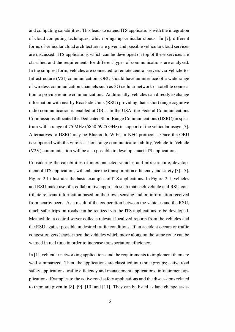
Considering the capabilities of interconnected vehicles and infrastructure, develop-
ment of ITS applications will enhance the transportation efficiency and safety [3], [7].
Figure-2.1 illustrates the basic examples of ITS applications. In Figure-2-1, vehicles
and RSU make use of a collaborative approach such that each vehicle and RSU con-
tribute relevant information based on their own sensing and on information received
from nearby peers. As a result of the cooperation between the vehicles and the RSU,
much safer trips on roads can be realized via the ITS applications to be developed.
Meanwhile, a central server collects relevant localized reports from the vehicles and
the RSU against possible undesired traffic conditions. If an accident occurs or traffic
congestion gets heavier then the vehicles which move along on the same route can be
warned in real time in order to increase transportation efficiency.
In [1], vehicular networking applications and the requirements to implement them are
well summarized. Then, the applications are classified into three groups; active road
safety applications, traffic efficiency and management applications, infotainment ap-
plications. Examples to the active road safety applications and the discussions related
to them are given in [8], [9], [10] and [11]. They can be listed as lane change assis-
6

Figure 2.1: Illustration of ITS applications
tance, co-operative merging assistance, pre-crash sensing, emergency vehicle warn-
ing, head-on collision early warning system, rear-end collision early warning system,
wrong way driving warning, stationary vehicle warning, traffic condition warning,
hazardous location warning, and control loss warning. The list can be extended to
many. In [10], speed management and co-operative navigation applications are also
examined for increasing transportation efficiency and to provide better traffic man-
agement. Lastly, possible services and requirements for the infotainment applications
are discussed in [10] and [12]. Infotainment applications can be classified into two
groups; co-operative local services and global Internet services. Point of interest
notification, local electronic e-commerce, etc., can be given as the examples of the
co-operative local services while insurance and financial services, fleet management,
parking zone management, personal agenda, media streaming, etc., are the examples
for the global Internet services.
As indicated in [1], system capabilities among the given technical requirements in-
clude radio communication capabilities, network communication capabilities, vehi-
cle communication capabilities, vehicle absolute positioning capabilities, and vehicle
communication security capabilities. Table 2.1 proposes the requirements of com-
munication mode and relevant message transmission frequencies for different ITS
applications. Although some of the use cases given in Table 2.1 require vehicle-to-
vehicle communication for co-operation with other vehicles, some of them require
7

only a wide area Internet connection. Note that given requirements in Table 2.1 are
not strictly defined rather they are recommended. It is concluded in [1] that vehicles
will be furnished with more communication, computing and sensing devices in future.
Thus, future vehicles will be equipped with On-Board Units having enhanced capa-
bilities to provide these requirements and to solve challenges of more sophisticated
ITS applications. Consequently, drivers will experience more enjoyable, comfortable,
safe, and environmental friendly trips.
Table 2.1: Requirements of communication mode and relevant message transmissionfrequencies of different ITS applications [1]
Use case Communication modeMin. transmission fre-quency
Criticallatency
Active road safety application requirementsLane change assis-tance
Co-operation awareness be-tween vehicles
10 Hz < 100 ms
Intersection collisionwarning
Periodic message broadcast-ing
10 Hz < 100 ms
Collision risk warn-ing
Time limited periodic mes-sages
10 Hz < 100 ms
Hazardous road con-ditions warning
Async. messages on eventsand message broadcasting
1 Hz < 1 s
Speed management performance requirementsRegulatory con-textual speed limitnotification
Periodic, permanent broad-casting of messages
1-10 Hz Not relevant
Green light optimalspeed advisory
Periodic, permanent broad-casting of messages
10 Hz < 100 ms
Co-operative navigation performance requirementsElectronic toll col-lection
Internet vehicle and unicastfull duplex session
1 Hz < 200 ms
Co-operative adap-tive cruise control
Co-operation awareness be-tween vehicles
2 Hz < 100 ms
Infotainment applications requirements
Local electroniccommerce
Full duplex communicationbetween RSU’s and vehi-cles, access to Internet
1 Hz < 500 ms
Media downloading Access to Internet 1 Hz < 500 msInsurance and finan-cial services
Access to Internet 1 Hz < 500 ms
Parking zone man-agement
Full duplex communicationbetween RSU’s and vehi-cles, access to Internet
1 Hz < 500 ms
8

The innovative and widely divergent benefits, and the social impacts of mobile Inter-
net access in vehicles are discussed in [13]. As the time consumed on road increases,
infotainment needs for the mobile Internet are becoming more commonplace in order
to provide an enjoyable and comfortable road experience to the drivers. This may
involve applications such as reading emails on voice, streaming media from Internet,
getting updates from socializing websites, navigating the route with Google Maps,
etc. Once the mobile Internet is integrated to vehicles, information-based applica-
tions like real-time surveillance of the vehicle are possible to be run on background
with the infotainment applications running on foreground. It is a fact that mobile
phones have been very common in a very short time after being introduced with the
Internet access. Quite likely, vehicles with the integrated mobile Internet are expected
be on roads in close-future [13].
Many organizations and governments have ongoing or completed ITS projects. Stan-
dardization efforts are still being continued. In Table 2.2, a few examples of the
European ITS projects are listed. The FRAME architecture given in [14] proposes a
systematic methodology for creating and designing ITS architectures based on given
specifications. It does not provide detailed designs for equipment rather describes
what is required and provides minimum stable framework necessary to deploy inte-
grated ITS architectures. Consequently, the FRAME is an abstract architecture for
ITS deployments. Applications are classified into several groups based on their use
cases and design methodology and requirements are defined based on these use cases.
It is possible to design and deploy any type of ITS applications via following the
proposed methodology of the FRAME, which results a complicated process and too
many definitions on the design. However, CarCoDe differs from FRAME in such a
way that applications are classified based on the timing requirements rather than the
use cases. In return of not supporting the applications with strict timing requirements,
CarCoDe proposes a simple approach for ITS deployments compared to the FRAME.
2.2 On-Board Unit Design
OBU stands for “On-Board Unit” which is an embedded platform to be installed into
vehicles in order to satisfy computing and communication requirements for Intelligent
9

Table 2.2: European ITS projects [1]
European ITS projectsStart/Endyears
Achieved goals
FRAME [14] 2001/2004Enhanced the European ITS Framework architecturewhich was originally proposed by an earlier Europeanproject, i.e., KAREN.
E-FRAME [14] 2008/2011
Further expanded the European ITS Framework Ar-chitecture in order to include the support of coopera-tive systems, and provided recommendations for thedevelopment and operational issues for a given ITSarchitecture.
CVIS [15] 2006/2010Designed, developed and tested required technologiesto support V2V and V2I communications.
HIDENETS [16] 2006/2008Developed and analyzed end-to-end resilience solu-tions for distributed applications and mobility-awareservices.
SAFESPOT [17] 2004/2008
Developed a Safety Margin Assistant increasing roadsafety, and extended driver awareness of the surround-ing environment.Proposed solutions for V2V and V2I communica-tions.Gathered safety-related information from in-vehiclesensors and communication network together.
GeoNET [18] 2008/2012
Developed geographic addressing and routing solu-tions over reliable and scalable communication ca-pabilities, enabled the exchange of information for aparticular geographic area located far away from theinformation source.Supported IPv6 deployment for in-vehicle OBU’s.
C&D (Connect andDrive) [19]
2008/2011
Designed and implemented a Cooperative-AdaptiveCruise Control (C-ACC) system via providingvehicle-to-vehicle and vehicle-to-roadside communi-cations over WiFi (IEEE 802.11p).Improved the road safety and efficiency.Reduced the emissions from vehicles.
Transportation Systems. An OBU may be designed and implemented specific to one
or few groups of ITS applications as the examples given in [20], [21], [22], [23] and
[24]. This kind of OBU’s do not have to be modular, extendable, or open-service in
both hardware and software designs because of the fact that they are aimed to specific
applications. This approach can be acceptable only if the performance criteria are too
high for the ITS application, or the cost is really a big issue on the design. Considering
the fast development on ITS technologies and wide-range of applicable applications,
10

OBU designs based on general purpose computer systems with many interfaces will
be more appropriate to satisfy today’s requirements for ITS applications. Such kind
of OBU designs should be modular, extendable, and open-service in both hardware
and software designs in order to introduce new ITS features in wide ranges.
Appropriate hardware support is essential while designing such a generic OBU con-
sidering the vehicular networking requirements for different types of ITS applications
given in [1]. At least one solution to communicate with nearby vehicles, roadside
units and infrastructure should be provided. Communicating with the in-vehicle sen-
sors and actuators are realized via the interfaces to in-vehicle networking buses such
as CAN or FlexRay. For the elements that are not accessible through the internal
networking buses of the vehicle, OBU should have required interfaces to connect
them directly. Bluetooth to make connections with mobile devices, audio and video
inputs/outputs, and well-designed man machine interfaces are the other issues to be
considered in OBU designs for improving user’s infotainment experience in vehicle.
Initially, it may have high cost to include all hardware support into one platform. Be-
sides, it is impossible to guess all of the future needs of ITS applications. However,
an embedded platform allowing for future extensions with hardware modularity and
proper hardware abstraction in software decreases the initial costs. In case of intro-
ducing new ITS features requiring external or improved hardware support, it will be
easier to extend or modify the design by means of hardware modularity, software
modularity and hardware abstraction properties.
Accordingly, hardware abstraction is a significant software requirement for generic
OBU designs. Differences in hardware are possible to be overcome via the bottom-
layer drivers in a layered software design. Furthermore, multitasking ability in soft-
ware provides new ITS applications to be executed easily in same platform over
a common hardware [2]. These requirements force usage of operating systems in
generic OBU software designs. In fact, the Linux kernel is nothing more than a hard-
ware abstraction layer which enables the interaction of upper layers with the hardware
via the device drivers [25]. Therefore, as stated in [2], a multitasking operating sys-
tem running over a Linux kernel is a perfect software platform for the development
of open-service, extendable, and portable OBU software designs.
11

Below, some examples of the previous OBU designs in both academic and industrial
communities are given.
European Union funded The-Easy-OBU project aims to design a new on-board unit
for vehicles which is capable of providing more accurate location information in chal-
lenging places like in the tunnels. Short term signal loss is a major challenge for
classical GNSS (Global Navigation Satellite System) applications. The Easy-OBU
project offers location precision improvement for non-real time ITS applications, i.e.,
offline tracking of the vehicle, measuring the total distance traveled, etc.
Electronic Toll Collection (ETC) systems are the oldest examples of ITS applications
which aim to eliminate the delay on toll roads by collecting the tolls electronically. It
is first proposed in 1959 as an idea for the Washington Metropolitan Area. In [21],
an example On-Board Unit design and implementation for the free-flow ETC system
is proposed considering that ETC system requirements are getting higher with the
rapid increases on number of the vehicles and the congestion on roads. 5.8G RFID
technology has been used as the key equipment of communication between the On-
Board Unit and the Roadside Unit in proposed work. In the meantime, a different
On-Board Unit design for ETC systems is proposed in [22] which they use DSRC to
make connections.
In [23], design requirements and challenges for long-range communication between
On-Board Units and Central Servers are discussed for the design of a Telematics Plat-
form to be used in Intelligent Transportation Systems. Real-time taxi matching, con-
text aware people tracking, smart ride sharing, etc., may be given as the application
examples of such a platform. Secure, synchronous, asynchronous and bidirectional
communication features are indicated as a must for the communication between On-
Board Units and Central Servers in order to implement proposed platform. HTTP
connections are used for messaging between the end-points via supporting the On-
Board Unit with 3G wireless cellular network interface. The drawback is that pro-
posed architecture aims only the location-based telemetry applications.
Another example of On-Board Unit design for the location-based ITS applications is
given and implemented in [24] which may be used by the commercial transportation
companies. An architecture and negotiation scheme is proposed to handle planning
12
of the route by multiple users before starting the trip. Management of the route and
real-time monitoring of the transported goods are aimed after the trip begins. A mi-
croprocessor based On-Board Unit is designed and implemented with Internet access
and GPS support in order to achieve these goals. Pre-positioned sensors to be used
in real-time monitoring of transported goods are connected to On-Board Unit via
the data acquisition devices. An application running on the On-Board Unit periodi-
cally sends synchronous messages to the central servers which the messages are com-
posed of information about the goods and exact location of the vehicle. Asynchronous
telemetries are also supported in both directions. However, application range is still
very restricted in proposed design which is similar to the previous works.
In [2], an On-Board Unit design with open-service architecture based on general pur-
pose computers in hardware are indicated to be a better option rather than the dedi-
cated ones. Adding new applications as executable software over a common hardware
platform has remarkable advantages. First of all, service updates do not require ad-
ditional costs in hardware platform. In the meantime, user experiences a much more
common interface with the system which is similar to standard PCs or smart phones.
Requirements of the software platform are also indicated in proposed work such that a
robust architecture is only possible with modular and portable applications which the
easiness of deployment is a must. An On-Board Unit satisfying these requirements
is designed and implemented in [2] such that a custom vehicle is widely sensorized
for context aware services. GNSS, video camera and odometer are some examples
of these sensors. All the sensors are directly connected to On-Board Unit. In other
words, these sensors do not belong to the internal network of vehicle since it is a cus-
tomized one. Proposed On-Board Unit design supports Bluetooth, WiFi and cellular
network (UMTS, GPRS, GSM) interfaces in order to provide vehicle-to-vehicle and
vehicle-to-infrastructure communications. Local communication among the vehicles
and roadside units is maintained via setting up peer-to-peer (P2P) networks. On the
other hand, Internet connection supported via the wireless cellular networks makes
it possible for vehicles to communicate with central servers located in long ranges.
Apart from these, Java virtual machine running over Linux Fedora Core 4 is the un-
derlying software platform for applications to be developed. Figure-2.2 represents the
service architecture for On-Board Unit given in proposed work. Software is designed
13

in layers such that different types of services are presented to upper layers resulting
that the topmost layer services have direct relation with the user. To summarize the
work in [2], a generic On-Board Unit is designed in both hardware and software.
Compared to the previous works, it is one step further because of that wide-range
of ITS applications are aimed on design. However, it is not feasible to make much
customizations on vehicles to sensorize them as in proposed work. Alternatively, On-
Board Unit could be supported to collect information from already-installed vehicle
sensors via reading from in-vehicle networking buses of the vehicle. Although most
of the vehicles are not internally equipped with many types of sensors, interfacing
with the existing ones decreases the cost and load of work.
Figure 2.2: On-Board Unit service architecture given in [2]
Another example of the open service vehicle embedded systems is described in [26].
Different from the previous work, On-Board Unit is designed to interface with in-
vehicle networking buses in order to collect data from vehicle sensors. Proposed de-
sign is implemented such that On-Board Unit is connected to vehicle subsystems via
the OBD-II connector existing in all vehicles of today [27]. V2V and V2I communi-
14

cations are provided through VANETs (Vehicular Ad-Hoc Network). The drawback is
that long-range communications are not considered for vehicles to communicate with
central servers. However, roadside units are connected to Internet and vehicles are ca-
pable of talking to remote infrastructure indirectly via the support of roadside units.
Two applications are developed in order to test the implemented design. Traffic Alerts
Broadcasting application is used to test the external interfaces of On-Board Unit in
various scenarios On the other hand, in-vehicle interfaces are tested via Eco-driving
Assistance application which monitors fuel-consumption in real time and guides the
driver with proper directions.
In [28], an industrial product is given which can be used as the communication unit for
development of ITS applications. The product has several internal hardware modules
and interfaces to deploy V2V and/or V2I applications as well as the CAN interface to
talk with in-vehicle subsystems. Internal GPS module is also integrated to the prod-
uct for location-based applications. It comes with a firmware which is nothing more
than a dedicated software stack for Intelligent Transportation Systems. The device is
controlled via the predefined command set embedded in firmware through the Ether-
net port residing on it. For instance, configuration of the CAN port and sniffing the
CAN data are realized by sending and receiving the corresponding message frames
over TCP/IP. With the together usage of a general purpose microprocessor and a good
software design, it allows development of ITS applications in wide ranges. Similar
industrial products offering even single solutions for ITS deployments do also exist
in market. However, as the nature of the industrial products, any information is dis-
closed with trade rights which makes them not appropriate to be used in academic
researches.
2.3 Android Operating System for Vehicles
Android is a combination of software platform and operating system for mobile de-
vices which is based on Linux operating system [29]. It is developed by Google,
and primarily being continued to be developed with newer versions. Although the
Android project started considering only the smart phones, Google has been nowa-
days working for publishing separate versions of Android which are optimized for
15

different kinds of mobile platforms including also the automobiles [30].
Mobile operating systems bring additional integrated mobility features differing from
the classical ones for desktop computers. These mobility features include supports
for cellular communication, GPS navigation, Bluetooth, Infrared and NFC in order
to provide extended communication capabilities while the users are in mobile. Ad-
ditionally, simple and non-complicated user interface is another important feature
of them [31]. Over the years, PC-based operating systems evolved to the embed-
ded ones, and lastly to the current mobile-device-oriented operating systems in past
decade. The most popular examples are Android, iOS, Windows Phone, Symbian and
webOS. Table-3 is given in [31] such that they are compared to each other in different
aspects. Considering the mobility of vehicles and above-mentioned requirements of
On-Board Units, Table-3 has actually significant importance for selection of the soft-
ware development platform. Android supports multiple CPU architectures being very
common in embedded platforms, runs over the Linux kernel inheriting the portability
and security features of Linux, and provides a shell interpreter to execute commands
of operating systems in user space. Furthermore, being very common in perspectives
of both of developers and users, openness to 3rd party application development, and
easiness for deployment of new applications are advantageous features of Android
operating system.
Android Operating System software stack is given in Figure-2.3 [32]. There are five
layers; kernel and low level tools, native libraries, Android runtime and Dalvik Vir-
tual Machine, application framework layer, and applications on top. Green items are
written in C/C++, blue items are written in Java. Full installation of Android system
has more blocks than shown in Figure-2.3. In [32], it is indicated that the kernel is
a modified version of the Linux 2.6 series kernel. As Android is supposed to run on
mobile devices, standard Linux kernel is optimized for power management, memory
management, process management, and runtime environment against the mobility
needs. Native libraries are written in C/C++ languages; however, applications are
normally programmed in Java language. Dalvik Virtual Machine (DVM) translates
Java byte code into Dalvik dex-code using just in-time compilation in order to run
applications. As stated in [31], such combination of applications with Dalvik Virtual
Machines brings up following features; enhanced security, efficient shared memory
16

Table 2.3: Comparison chart for the most-popular mobile operating systems
Android iOSWindowsPhone
webOSSymbianOS
Deployedsoftwaredevelopmentenvironment
Java,C/C++,Phyton, Lua
Objective C .NET JavaScript
C/C++, JavaME, Phy-ton, Ruby,Flash Lite
Market size Very high High Medium Very low Very low
SDK platformWindows,Linux, MacOS X
Mac OS X,Snow Leop-ard
Windowsonly
Mac OS X,Linux, Win-dows
Windows,Linux
Openness todevelopers
Very high Very low Medium Very high High
OS family Linux DarwinWindowsCE, NT
Linux RTOS
SupportedCPU architec-ture
ARM,MIPS, x86
ARM ARM ARM ARM
Futureprospect
Very high High Medium Low Low
management, preemptive multitasking, UNIX user identifiers (UID), and file permis-
sions with the type-safety concept of Java. Every Android application runs in sepa-
rate processes having unique UID’s with distinct permissions. Applications normally
cannot read or write each other’s data; however, resource sharing is possible between
applications only if the required permissions are granted during the installation. Ap-
plication framework layer is written in Java and provide application programming
interface (API) to the developers via wrapping the underlying native libraries and
Dalvik capabilities. Applications may have multiple components such as activities,
services, broadcast receivers and content providers. These components may interact
with other components of the same or different application via the intents [32], [30].
Open issues of Android for automotive infotainment applications are discussed in
[33]. Based on the discussions, a software architecture is defined to be used in in-
vehicle infotainment systems. As indicated in [33], Android has no automotive spe-
cific features yet, i.e., support of the CAN networks. However, underlying Linux 2.6
kernel has support for CAN via the SocketCAN drivers. SocketCAN is an implemen-
tation of CAN protocols for the Linux kernel [34]. However, it is not ported to user
17

Figure 2.3: Representation of Android system architecture
space of applications in default Android installations. So, Android is customized in
the proposed work such that a safe mechanism for allowing trusted applications to
access vehicle’s functions (reading/writing on the CAN bus) in application Java code
is provided. Since [33] does not consider V2I communication needs of the infotain-
ment systems in long ranges although the Android OS provides great opportunities,
this work does not conform to the today’s needs of ITS applications. Nevertheless,
customization of the Android with automotive specific features is yet a significant
contribution.
In [35], an example design of Android based automotive middleware architecture for
plug-and-play applications is proposed. Today’s vehicles are installed with several
tens of Electronic Control Unit (ECU)’s which forms a distributed network to con-
trol various functionalities such as cruise control, automatic parking system, etc. The
trend is to improve these functionalities with more re/programmable features in order
to meet the demands for reconfigurable cars, software version upgrades, or installa-
tion of new applications in plug-and-play form. It is indicated that the existing auto-
motive software platforms are not appropriate for dynamic reconfiguration with new
18

features and plug-and-play applications. Proposed work addresses the plug-and-play
challenges of the automotive systems, and makes use of Android to build distributed
software architecture for electronic control units in vehicle. It should be noted that
this work differs from the previous ones such that a physical OBU device does not
exist. Rather, ECU’s are improved which makes the vehicle smarter itself. Plus,
plug-and-play features of the ECU’s make the design highly modular and extendable.
However, possible drawback in [35] is that these customizations and improvements
are not feasible to be applied to the vehicles of today on roads.
IEEE announced 802.11p standard for WAVE (Wireless Access in Vehicular Environ-
ments) to be used in short-range communications. An inter-vehicle communication
(V2V) scheme is proposed in [36] such that proposed design is implemented and eval-
uated on a smart phone operating with Android operating system. 802.11p hardware
is abstracted as the WiFi hardware existing on smart phones. It is concluded that pro-
posed WAVE architecture works well under many different vehicular ad-hoc network
(VANET) scenarios. Additionally, it is possible to be easily installed in any Android
device which is highly motivating for Android based software designs in On-Board
Units.
Another example work of Android usage in ITS applications is given in [37] which
aims to increase survival rates in traffic accidents. Considering that the time between
when an accident occurs and when the first responders are dispatched to the scene
is highly critical, eliminating the corresponding delay between them is possible with
accident detection and notification applications. Such applications are supposed to
sense the traffic accidents and immediately notify the emergency personnel. Proposed
scheme is implemented on smart phones operating Android or iOS. Accidents are de-
tected using the accelerometers already equipped in most smart phones and acoustic
data measurements. A central emergency server is notified via the cellular commu-
nication link with GPS coordinates, accident photographs, and related data records.
VOIP communication channels are also provided after the accident for emergency
directions. This work contributes a formal model for detecting accidents on roads. It
shows how to provide situational awareness to the first responders in accidents via the
usage of sensors, network connections, and web services. Integrated mobility features
of mobile operating systems such as cellular communication, GPS, and accelerome-
19
ters make the deployment of design much easier. This work can easily be introduced
to open-service ITS platforms without any cost, which is another strong motivation
for Android based software designs in On-Board Units.
Google is up to publish a dedicated version of Android operating system for auto-
mobiles which is to be called as Android Auto [30]. The most fundamental change
occurs in the user interface such that simple and intuitive screens welcome us con-
sidering the safety on roads. Development of infotainment applications focusing on
Google services are firstly introduced with Android Auto. Moreover, collecting ve-
hicle information from in-vehicle buses is expected to be via OBD-II interface in
vehicle. Many dominating automaker companies are partnered such as Audi, Ford,
and Volkswagen. It is indicated that application development is currently open to
developers. Application programming interface and programming guides are already
published. Considering the Google’s power on mobile platforms, it is highly expected
that Android will dominate the vehicle infotainment systems on near future.
2.4 The WebSocket Protocol
WebSocket is a new generation transport protocol for web applications providing full-
duplex, i.e., bidirectional, communications over a single TCP connection [38]. IETF
(Internet Engineering Task Force) standardized the WebSocket protocol as RFC6455
in 2011 against the known issues of existing HTTP based bidirectional communica-
tion techniques. In the standard HTTP model, a server is not able to initiate a connec-
tion with a client nor allowed to send HTTP messages without being requested. Thus,
it is impossible for the servers to push asynchronous events to the clients via HTTP
protocol. Several solutions to that problem has been proposed and applied throughout
the years such as polling, long polling, and HTTP streaming. Below, historically past
techniques for providing bidirectional Web communication are discussed first [39];
after that, working principles of the WebSockets and the related work are given.
In traditional polling technique, the client periodically sends regular HTTP requests
to the server in order to check for new updates and content. If there does not exist
any available data to be sent at this moment then the server responds with an empty
20

HTTP message. Tolerable latency of the client for new updates determines the polling
frequency. The drawback is that continual polling may consume a big amount of
network bandwidth and burden the server due to the processing of each request.
In long polling technique, the client initiates the connection and makes the first re-
quest. Then, it starts waiting for a response. The server keeps the request open until
an update is available, or timeout occurs. Whenever there exists some available data,
i.e., an update, the server sends a complete HTTP response to the client. After that,
the client is free to send a new long poll request immediately upon receiving the first
response. Figure-2.4 gives an illustration of working principles in both polling and
long polling techniques. Persistent or non-persistent HTTP connections may be set up
for polling. If the long polling mechanism, as well as the traditional polling, occurs
on a persistent HTTP connection then the additional overhead of establishing a new
TCP/IP connection for each poll request is avoided. On the one hand, HTTP headers
still cause an overhead for small messages. On the other hand, the amount of data to
be sent from server to client may be larger than the maximum payload size of HTTP
protocol. In this case, application developer is responsible from fragmenting or de-
fragmenting of the messages. Timeout should be considered carefully in long polling
technique. It is indicated in [39] that the client may receive a 504 Gateway Timeout
answer from proxy if the timeout value is chosen too large. Caching is another is-
sue to be taken care of since the long poll HTTP requests are totally transparent and
caching may interfere with the bi-directional flow.
HTTP streaming keeps a request open indefinitely on the contrary of long polling.
The client makes initial request and waits for responses. Whenever an update be-
comes available, the server sends it to the client. After receiving a part of response,
the client does not terminate the connection. The drawback for HTTP streaming
is that intermediaries (proxies, caching proxies, gateways, etc.) in network infras-
tructure may be involved in transmission. There is no requirement such that partial
responses for HTTP streaming should be immediately forwarded in network middle-
ware. In addition, HTTP headers still cause overheads. Next, clients are not able to
send large volumes of data to the server using HTTP requests although the server is
capable of sending data in partials via multiple responses to the requests. In fact, these
drawbacks for HTTP streaming are also valid for all HTTP based bidirectional com-
21

Figure 2.4: Polling vs. long polling
munication techniques since the HTTP protocol was not initially meant to be used for
full-duplex communication [38].
There exist several web application development frameworks which provide server-
push programming and mostly based on above-mentioned techniques. Ajax use long
polling techniques over long-lived HTTP connections via the asynchronous HTTP
requests for server updates. Comet, known as Reverse-Ajax, is able to push mes-
sages without explicitly being requested likewise in HTTP streaming. BOSH (Bidi-
rectional Streams over Synchronous HTTP) emulates the normal TCP connection
over HTTP via the synchronous requests with an improved long polling technique.
Bayeux sets up two HTTP connections for asynchronous full-duplex communication
and uses both of HTTP long polling and HTTP streaming techniques. It should be
also noted that Bayeux is indicated to be capable of running on non-HTTP transport
protocols as well. [40].
All of the above-mentioned web application development frameworks are primarily
designed for HTTP which is an old protocol for modern web applications [41]. De-
spite the fact that they provide full-duplex communication via their own ways, pro-
cessing of HTTP messages and using separate connections for upstream/downstream
data causes overheads to both of network and CPU resources. A simpler solution
would be to use a single TCP connection for outgoing and incoming data without us-
22
ing HTTP as the transport protocol via an event-driven mechanism. This is what the
WebSocket protocol provides [38]. IETF states that WebSocket protocol is primarily
designed to supersede existing HTTP based full-duplex communication technologies.
However, it still benefits from HTTP such that it works on ports 80 and 443 as well
as supports the HTTP proxies and intermediaries in network middleware.
The WebSocket protocol is designed to work well with the pre-WebSocket world in
order to provide backward compatibility. The protocol specification defines that the
WebSocket connection starts its life as an HTTP connection. Then, it switches from
HTTP to WebSocket. Switching operation from HTTP to WebSocket protocol is re-
ferred as the handshake. First, the WebSocket client sends HTTP request to the server,
i.e., client handshake, indicating that it wants to switch protocols. If the server under-
stands the WebSocket protocol, it agrees to the protocol switch and informs the client
with a HTTP response, i.e., server handshake. Once the client and server have both
sent their handshakes successfully, HTTP connection between them breaks down and
replaced by the WebSocket protocol over the same underlying TCP/IP connection.
The newer WebSocket connection uses the same ports as HTTP (80) and HTTPS
(443) by default [42]. After that, data transfer part begins. WebSocket data frames
can be sent back and forth between the client and the server in full-duplex mode.
Both of the text and binary frames are supported. Figure-2.5 indicates the WebSocket
connection in summary.
Data transfer between the server and the client occurs via messages. On the wire,
a message may be composed of one or more frames if the implementation supports
fragmentation and defragmentation though the WebSocket protocol specifies frag-
mented frames. In other words, implementation specific limitations may occur re-
garding the frame size or total message size. Figure-2.6 shows the framing fields of
WebSocket protocol [38]. FIN bit, which is the first bit in frame, indicates that this is
the final fragment in a message. After that, 3-bits are reserved for future extensions.
Opcode field indicates the interpretation of payload such as continuation frame, text
frame, binary frame, ping request, connection close information, etc. Then, the MSK
bit comes to indicate that payload data is masked. Payload length can be defined in 7-
bits, 7+16 bits, or 7+64 bits. If payload length is given between 0-125 then extended
payload length is not necessary. If payload length is equal to 126 then following two
23
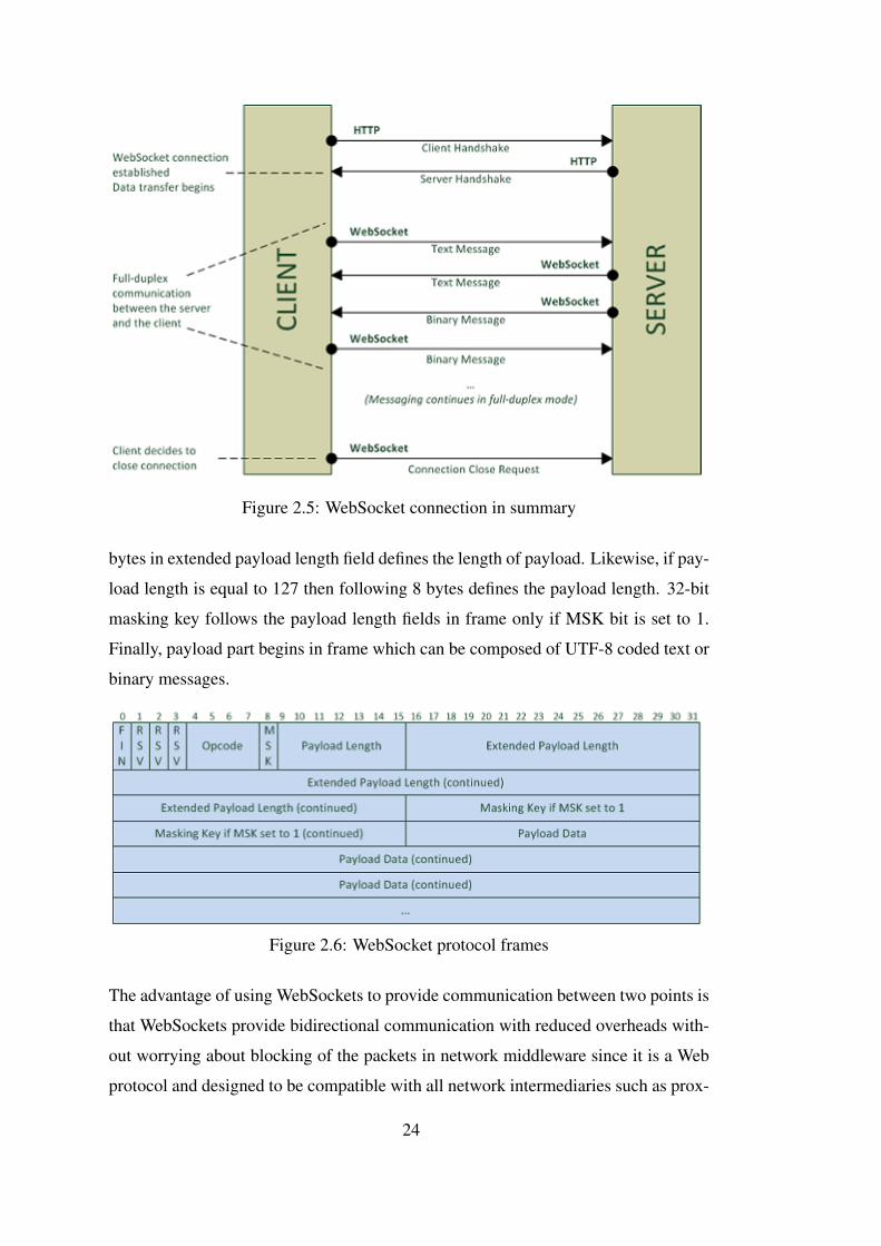
Figure 2.5: WebSocket connection in summary
bytes in extended payload length field defines the length of payload. Likewise, if pay-
load length is equal to 127 then following 8 bytes defines the payload length. 32-bit
masking key follows the payload length fields in frame only if MSK bit is set to 1.
Finally, payload part begins in frame which can be composed of UTF-8 coded text or
binary messages.
Figure 2.6: WebSocket protocol frames
The advantage of using WebSockets to provide communication between two points is
that WebSockets provide bidirectional communication with reduced overheads with-
out worrying about blocking of the packets in network middleware since it is a Web
protocol and designed to be compatible with all network intermediaries such as prox-
24

ies, domain name servers, etc. The protocol differentiation is meaningful only at the
end-points, i.e., the server and the client host machines. In other words, a WebSocket
client can communicate with a WebSocket server in all possible paths existing on net-
work which browsing pages on Internet is also possible. Considering the capabilities
of WebSockets and the current needs for Web communication, it is standardized in
HTML5 for developing interactive Web pages [42]. However, it is possible to be used
in a wide range of applications including the embedded applications, wireless sensor
networks, etc., [43].
In [43], one way latency in WebSocket communications are evaluated and compared
to HTTP polling and long-polling mechanisms. According to the results, HTTP
polling has far away the highest latency value compared to others. WebSocket and
long-polling in HTTP have almost equal latency values in short-ranges; however, the
WebSocket protocol offers lower latencies while the range increases. In [44], The
WebSocket protocol is analytically examined against the amount of generated net-
work traffic and the data transfer time comparing it to the plain TCP protocol. It is
indicated that the WebSocket protocol is a powerful mechanism for implementation
of full-duplex asynchronous Web-based data streams. In [45], [46], and [47], Web-
Socket applications relevant to Intelligent Transportation Systems are given which are
the great motivations for WebSockets to be used in connections between the vehicles
and the infrastructure in long-ranges.
25

26
CHAPTER 3
CARCODE ARCHITECTURE AND ON BOARD UNIT DESIGN
AND IMPLEMENTATION
3.1 Car Content Delivery (CarCoDe) Architecture
Intelligent Transportation Systems in the most general form are comprised of the
cooperation of vehicles, roadside-units, user devices and infrastructure, which can be
named as the end-points in ITS applications. The rules of cooperation among these
end-points and how they communicate with each other should be defined clearly in
a generic ITS architecture targeting multiple types of ITS applications. By means of
such an approach, several smart applications will be possible to be deployed without
interfering with each other.
In fact, application requirements force the existence of different kinds of end-points
and the way of communication between them. For instance; an application for stream-
ing media from a common remote host on the road needs only vehicles and media
hosting infrastructure to be defined in architecture. A wide-range communication
channel, preferably the Internet, is a must to implement it. However, if the user desires
to access and play the media in his/her personal desktop computer placed at home
then this approach fails. A new type of end-point (user-devices) and corresponding
communication rules should be introduced to the architecture. For road safety ap-
plications, vehicle-to-vehicle communication will be most probably required. Smart
traffic management applications such as congestion-aware navigation or electronic
toll collection systems may require existence of roadside-units. Consequently, ITS
architecture highly determines the types of applications.
27

In scope of this thesis work, a simple but generic system architecture (CarCoDe)
for Intelligent Transportation Systems is proposed. Figure 3.1 gives an overview of
the proposed architecture. There exist four different types of end-points which are
service providers, roadside units, vehicles and user devices. They are assumed as the
clients of CarCoDe architecture. In middleware, central servers act as smart routers
to forward messages between these clients, i.e., the end-points. Unique identification
numbers are given to the clients and central servers keep a list of access permissions
matching with the client identification numbers. Based on these permission lists on
central servers, clients are able to communicate with each other in architecture. For
example; the vehicle with ID#1 talks to the vehicle with ID#2 in path-A. In path-B,
the vehicle with ID#3 talks to the service provider which is placed in long-range.
Other types of communication examples are also shown in paths-C, D, and E.
Figure 3.1: CarCoDe system architecture overview
28
Consider the scenario such that Company-T provides CarCoDe architecture, middle-
ware and required framework to other companies in order for ITS applications to be
developed. Below, three different examples of ITS applications are described in order
to explain use cases of proposed architecture.
• In the first application, Company-X wants to setup a congestion-aware navi-
gation application for vehicles. So, Company-X uses the middleware services
provided by Company-T. Then, Company-X installs roadside units to detect lo-
calized real-time congestion information for roads, gets a service provider to
manage the application, and develops vehicle side of application in order to
give service of congestion-aware navigation to the payer vehicles.
• In the meantime, Company-Y develops a safety application of early warning
system for icy-roads. Another service provider infrastructure is setup for this
application by Company-Y which is totally unaware of the first one. Vehicle
side of application is developed in such a way that it senses icy roads by observ-
ing ESP signals and other in-vehicle sensors. In addition, each vehicle sends its
location information to the service provider periodically. As soon as icy road
is detected by any of the connected vehicles, a warning message is broadcasted
to the vehicles behind on same route by requesting identification numbers of
those vehicles from corresponding service provider of the application.
• In addition to the previous applications, Company-Z develops an application to
access and stream users own media on the road from devices placed at home. In
this case, it is assumed that users already know own identification numbers of
their vehicles and devices. User-device side of the application is developed in
such a way that it outputs the media stream while vehicle side of the application
is developed for listening to this stream. So, there is no need to setup any addi-
tional infrastructure to realize such kind of user-device connected infotainment
application.
Examples can be reproduced to many. CarCoDe system architecture aims to pro-
vide middleware services to different kinds of ITS applications which are expected
to run simultaneously and unaware of each other. This thesis work defines the Car-
CoDe system architecture in a generic way such that implementation requires specific
29

definitions of the types, protocols, interfaces, communication media, etc. Therefore,
design considerations for the architecture and relationship information between the
main blocks are given below first. Then, design and implementation of an On-Board-
Unit (OBU) for vehicles is given and evaluated as the second part of this thesis work,
which may be counted as the partial design (vehicle side) of proposed CarCoDe ar-
chitecture. Complete definition and design is left as future work.
As seen on Figure 3.1, two end-points are able to talk to each other indirectly over
3rd node in CarCoDe middleware. This is because CarCoDe aims to support both
of long-range and short-range communications in one and simple way. However,
safety applications may require very hard requirements such that CarCoDe system
architecture may not overcome. So, CarCoDe system architecture may be extended
in future so that wireless ad-hoc networks are supported as the second alternative for
short-range communications in order to be used in vehicle-to-vehicle communications
with hard requirements.
3.1.1 CarCoDe Applications
Software stack for CarCoDe system architecture is proposed in a layered-scheme
such that application code is abstracted from lower layers. Figure 3.2 shows the
proposed software stack for end-points in CarCoDe architecture. Applications use
the services provided by CarCoDe framework which will be developed distinctively
for each type of end-point, i.e., service providers, roadside units, vehicles, and user
devices. Underlying infrastructure of the host machines may differ from each other;
however, CarCoDe framework should be able to present common methods and fields
to application programmers in order to support 3rd party application development and
to provide portability of applications. Java programming language seems a reasonable
selection to develop application code because of its portability features compared to
the other programming languages.
As seen on Figure 3.2, each application is given a unique identification number similar
to ports in transport layer of classical socket communication so that distributed execu-
tion of applications can be realized with instances running on different host machines.
For instance; different instances of same application will run on vehicles, roadside
30

Figure 3.2: CarCoDe system architecture software stack for end-points
units and corresponding service provider for the above-mentioned congestion-aware
navigation application. Another benefit of giving unique identification numbers to
each application is that multiple applications can run on same host by differentiat-
ing them with their identification numbers provided that underlying infrastructure
of the host machine has multiprocessing ability. In this case, prioritization of the
applications running on same host becomes an issue to be handled in order to pro-
vide safety-related applications given with the highest priority. With a good system
engineering work, application types can be classified into different types such that
safety-related, diagnostics, information, and infotainment. Then, multiple ranges of
application identification numbers are defined and assigned based on this classifica-
tion. Finally, application priority levels are allowed to be changed with restrictions in
CarCoDe framework based on the classified identification numbers for applications.
Besides, communication messages between several instances of an application also
require different priority levels considering the overloading of messages. So, priority-
based message queues should be defined in order to solve this issue for applications.
Optimal priority levels and queue sizes can be determined based on the specific im-
plementation and different use cases.
3.1.2 CarCoDe Framework
CarCoDe Framework is the software stack between applications and infrastructure in
proposed CarCoDe architecture. It is expected to be developed distinctively for each
kind of end-points in order to present a common interface to applications running on
31

top. By this way, application programmers will not worry about the underlying infras-
tructure and resources. Additionally, CarCoDe framework will provide the integrity
of overall architecture. In other words, it is responsible of managing connections
to the middleware in order to provide communication links between the application
instances running on different hosts.
It is recommended to develop CarCoDe framework on top of an operating system
in order to exploit hardware abstraction properties of operating systems. It may be
developed in different programming languages rather than Java based on underlying
resources. In this case, Java Virtual Machines and appropriate libraries should be
provided to run CarCoDe applications and to interface with Java code. Software de-
sign for CarCoDe framework can be divided into two layers; up and down. Resource
management is expected to be handled by down-layer via developing wrapper codes
for each resource type. Appropriate fields and methods may be defined here and pre-
sented to be use of above layers including the topmost application. Up-layer handles
the integrity of overall architecture via setting up connections to the architecture mid-
dleware and manages the applications via starting and stopping them. Application
instances which are running on different hosts in a distributed fashion will be able
to communicate with each other once the integrity of architecture is provided. Be-
sides, configuration of the corresponding host (if necessary) and parameterization of
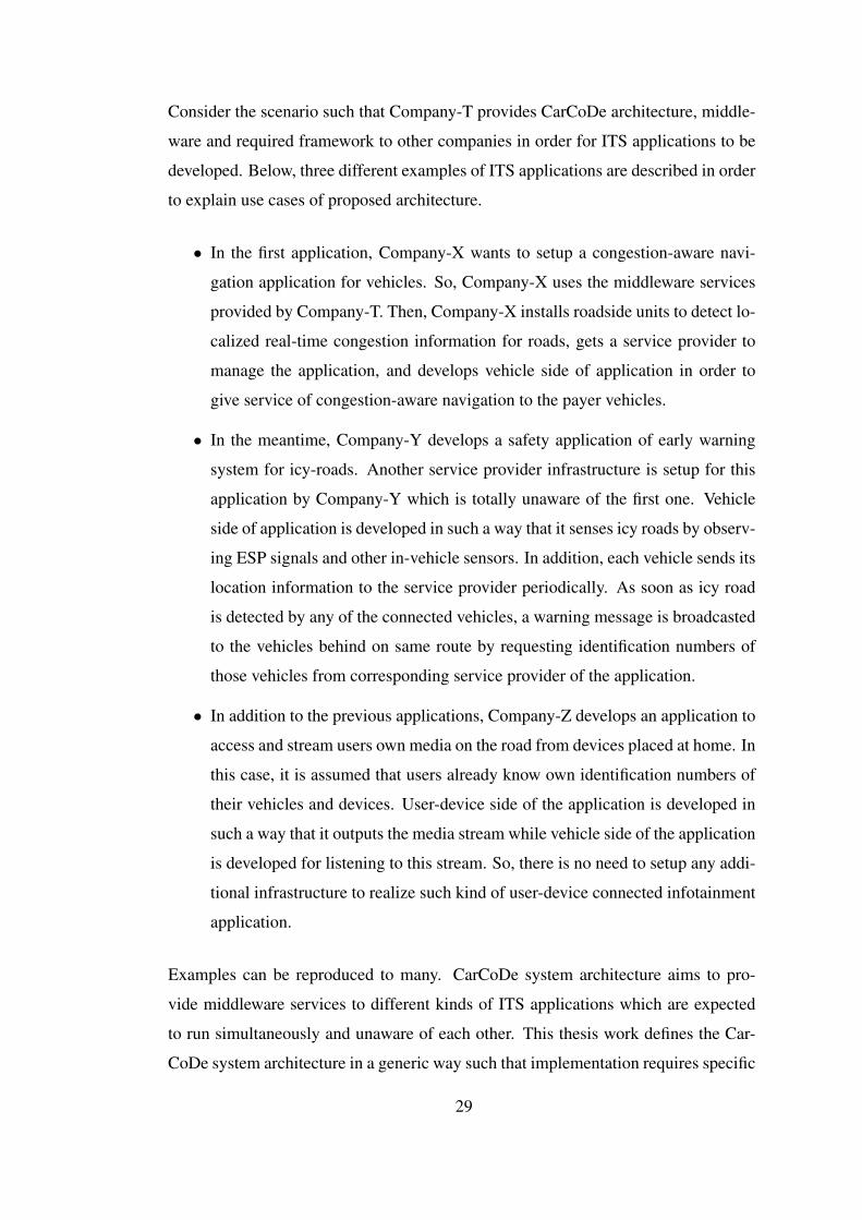
specific values should be also managed by CarCoDe framework. Figure 3.3 gives
example software design for CarCoDe framework to be used in vehicles.
Applications may require different services in different types of end-points. In other
words, an application instance running on roadside unit most probably will not need
to access CAN bus although it is almost a prerequisite for vehicles. So, CarCoDe
framework is presented to application developers distinctively. Moreover, it is rea-
sonable that different companies have different physical infrastructures which allow
accessing same type of resources in different ways. Underlying operating system usu-
ally handles this issue. But, different implementations to access same type of resource
may be required in some cases. Wrapper codes for multiple implementations and pa-
rameterization of the resource brand solves this issue. Another issue for vehicles is
that CAN frames to talk with in-vehicle systems are standardized in OBD-II stan-
dard for diagnostic and information purposes; however, companies are free to define
32
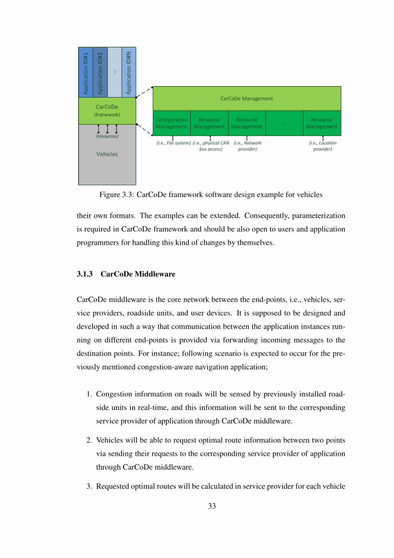
Figure 3.3: CarCoDe framework software design example for vehicles
their own formats. The examples can be extended. Consequently, parameterization
is required in CarCoDe framework and should be also open to users and application
programmers for handling this kind of changes by themselves.
3.1.3 CarCoDe Middleware
CarCoDe middleware is the core network between the end-points, i.e., vehicles, ser-
vice providers, roadside units, and user devices. It is supposed to be designed and
developed in such a way that communication between the application instances run-
ning on different end-points is provided via forwarding incoming messages to the
destination points. For instance; following scenario is expected to occur for the pre-
viously mentioned congestion-aware navigation application;
1. Congestion information on roads will be sensed by previously installed road-
side units in real-time, and this information will be sent to the corresponding
service provider of application through CarCoDe middleware.
2. Vehicles will be able to request optimal route information between two points
via sending their requests to the corresponding service provider of application
through CarCoDe middleware.
3. Requested optimal routes will be calculated in service provider for each vehicle
33

based on the congestion information, and they will be sent to the vehicles.
4. Until all the vehicles reach to their destination points, vehicle locations and
congestion information will be updated in real-time, and navigation will con-
tinue.
Additional smart features may be also added to middleware in order to secure com-
munication between application instances and to reduce processing loads of service
providers. These can be keeping the records of client identification numbers and
giving access tokens to them for authentication, developing a back-end management
scheme for the overall architecture, blocking insecure communications, keeping a list
of active and online clients, additional data-logging features, etc. Development of a
backup mechanism may also be considered in order to prevent any possible service
interruption. Although CarCoDe middleware may contain only one central server to
give service to all clients, various designs containing multiple servers are possible
based on the underlying network resources.
It is not feasible to setup such a big network from beginning. In fact, Internet network
presents such a big infrastructure to make connections in very long ranges. Advances
on mobile wireless technologies over cellular networks present a great opportunity to
make connections outside from vehicles. Therefore, Web communication protocols
may be used to setup connections between the clients on end-points and the servers
on middleware under the concept of Internet of Things.
3.1.4 Communication in CarCoDe Architecture
It is assumed that Internet is the underlying network for communications in CarCoDe
architecture. Additionally, end-points talk to each other in full-duplex mode over Web
protocols under the concept of Internet of Things. In such a network, end-points are
defined as the clients and at least one server is placed into the middleware in order to
bridge connections between them. In this architecture, i.e., server-client based, each
end-point is only able to talk with central servers in middleware. Direct communica-
tion between the end-points, i.e., vehicle-to-vehicle communication in short ranges,
is only possible via extending the architecture such that localized P2P networks are
34
introduced over DSRC protocols.
Accordingly, communication between multiple instances of CarCoDe applications is
maintained via the servers placed in CarCoDe middleware resulting that distributed
execution of applications is supported. As mentioned before, unique identification
numbers are given to each client which can be used as device addresses in CarCoDe
network for differentiation of them. Besides, CarCoDe middleware contains central
servers to give gateway services, i.e. forwarding messages between the clients. In
case of installing multiple servers to be used as gateways in CarCoDe network, an
intelligent algorithm may be designed and implemented in order to select best gate-
way with minimal latency for clients and to distribute network loads efficiently in
CarCoDe middleware. For instance, if HTTP is used as the transportation protocol
for CarCoDe messages then HTTP payload generated by the source client will be
forwarded in HTTP request/response messages until the destination client gets the
message. Another aspect in CarCoDe architecture is to provide execution of multiple
applications in same host machine where the applications are supposed to be run-
ning unaware from each other. So, as to remember, applications are also given with
unique identification numbers to differentiate them. Exploiting the layered design of
software, CarCoDe framework is responsible of delivering application messages up
or down based on the application identification numbers. Figure 3.4 shows the pos-
sible framing fields for CarCoDe messages to be transmitted between the application
instances. Note that CarCoDe message frame shown below will be encapsulated in
payload of the transportation protocol to be used.
Figure 3.4: Sample message frame for communications in CarCoDe
Proposed messaging scheme may be likened to the messaging via classical sockets
which occurs in lower layers of network infrastructure in IP communications. Al-
though socket communication has lower overhead, it is not appropriate to be used
in Internet network. Because, network intermediaries may block the messages due
to security issues and two clients behind different NAT’s (Network Address Transla-
35

tion) may not be able to talk to each other unless the messages are ported. Therefore,
a similar approach to the socket communication is applied in application level for
CarCoDe architecture based on existing Web protocols.
Message transmission between two instances of an application is expected to be in
following order for proposed layered-design of software (ignoring the queuing of
messages);
1. Sender host prepares the payload in application code and adds application iden-
tification number to the message frame. Then, it indicates whom to send the
message via adding the client identification number of destination host. Here,
a query may be possible to ask for identification numbers of other clients, i.e.,
service providers, locationally-closed vehicles, user devices, etc., from middle-
ware elements if they support this feature.
2. In CarCoDe framework up-layer, own client identification number of the host is
added to message frame without interrogating the application code developed
by application programmers. A predefined access token may be also added to
message and all frame data may be encrypted for security purposes.
3. In CarCoDe framework down-layer, operations related to transportation pro-
tocol are expected to be realized. For instance, the CarCoDe message frame
received from up-layer is placed into HTTP frames if the HTTP connections
are used. Then, appropriate gateway address is obtained and corresponding
HTTP request is sent to the Web-server acting as a gateway in CarCoDe mid-
dleware. Note that, additional operations and overheads are expected to occur
in operating system level until the message data physically accesses to under-
lying network infrastructure.
4. In CarCoDe middleware, the CarCoDe message frame is extracted from re-
ceived data based on the transportation protocol. Decryption occurs if it is
required and access token is verified. Identification number of the destination
host which is embedded inside the message is checked. Then, CarCoDe mes-
sage frame is again encapsulated in payload of the transportation protocol and
forwarded to the destination point. It is possible that destination point may be
36
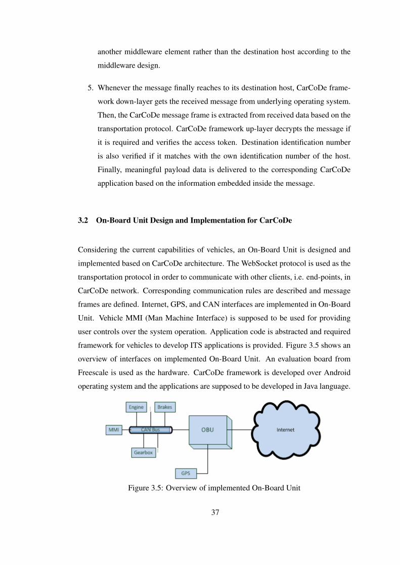
another middleware element rather than the destination host according to the
middleware design.
5. Whenever the message finally reaches to its destination host, CarCoDe frame-
work down-layer gets the received message from underlying operating system.
Then, the CarCoDe message frame is extracted from received data based on the
transportation protocol. CarCoDe framework up-layer decrypts the message if
it is required and verifies the access token. Destination identification number
is also verified if it matches with the own identification number of the host.
Finally, meaningful payload data is delivered to the corresponding CarCoDe
application based on the information embedded inside the message.
3.2 On-Board Unit Design and Implementation for CarCoDe
Considering the current capabilities of vehicles, an On-Board Unit is designed and
implemented based on CarCoDe architecture. The WebSocket protocol is used as the
transportation protocol in order to communicate with other clients, i.e. end-points, in
CarCoDe network. Corresponding communication rules are described and message
frames are defined. Internet, GPS, and CAN interfaces are implemented in On-Board
Unit. Vehicle MMI (Man Machine Interface) is supposed to be used for providing
user controls over the system operation. Application code is abstracted and required
framework for vehicles to develop ITS applications is provided. Figure 3.5 shows an
overview of interfaces on implemented On-Board Unit. An evaluation board from
Freescale is used as the hardware. CarCoDe framework is developed over Android
operating system and the applications are supposed to be developed in Java language.
Figure 3.5: Overview of implemented On-Board Unit
37

3.2.1 Hardware
Current implementation for OBU with minimal features requires three interfaces as
given on Figure 3.5. These are physical CAN interface to connect with in-vehicle
network, physical wireless cellular communication interface to connect with Internet,
physical GPS interface to get location information on runtime. Bluetooth and DSRC
supports are the future extensions. Other types of in-vehicle network protocols like
FlexRay and MOST may be also supported additional to the CAN interface. Although
the current implementation for OBU is supposed to use vehicle’s MMI via accessing
to CAN bus, another specific MMI for OBU including the own display, audio/video
channels and user control elements to be placed in vehicle dashboard may be de-
signed and implemented. Additionally, auxiliary audio inputs, USB and SD-Card in-
terfaces enrich the infotainment features. Besides, performance requirements enforce
that main processing element should be as powerful as to run multiple applications
without any degradation in performance, possibly having at least one multi-core pro-
cessor, enough memory and storage capacities. Assuming that an operating system
running on top of the Linux kernel will be used to setup the software environment and
to provide the required driver support, it is fundamental that processing architecture
for OBU should be supported by the Linux kernel.
Hardware may be designed based on general purpose microprocessors by adding ap-
propriate peripherals to the circuit. There exist several ASIC (Application Specific
Integrated Circuit) chips on market which brings solutions to the connectivity issues
such that CAN controller chips to connect with CAN bus, GPRS/3G modem chips to
connect with cellular data networks, corresponding transceiver chips to interface with
physical infrastructures, etc. Moreover, PLD (Programmable Logic Device) chips
may be used to develop own solutions for several issues on design. In fact, the main
point on hardware design for OBU is that modularity and extendibility issues should
be taken into consideration for future extensions. Within the scope of this thesis work,
a development board is used, as is, instead of designing own hardware for OBU imple-
mentation. SABRE-AI platform manufactured by Freescale which is based on ARM
architecture fits perfectly to the above-mentioned requirements of hardware design.
Figure 3.6 shows the top-view of SABRE-AI [48] .
38

Figure 3.6: SABRE for Automotive Infotainment Based on the i.MX6 Series
SABRE-AI platform is composed of two boards which are the CPU card and the Main
board. The CPU card contains the main processor and mostly the controller circuits
for peripherals. It is plugged into the Main board which the physical transceiver
circuits exist. Together with, the SABRE-AI platform presents following features for
developers [48];
• Processor
– i.MX6 Quad-core processor based on ARM Cortex A9 CPU cores
– Up to 1 GHz speed
• Memory
– 2 GB DDR3 RAM running up to 532 MHz
– 32 NB 16-bit parallel NOR flash
– 8-bit NAND flash socket
• Connectivity
– Ethernet interface
– Low and high-speed CAN interfaces
39

– GPS module connector (UART)
– Bluetooth module connector (IIS + UART)
– High-speed USB OTG interface
– Dual USB host connectors
– SD Card interface
– 1.5 Gb/s SATA interface
– MIPI CSI interface
– MLB150 INIC interface
– MLB 25/50 INIC interface
– I2C module connector
– De-serializer input for video/camera input
– Triple video DAC with analog video inputs for video/camera input
• Display
– 2 x LVDS outputs to connect touch screens
– HDMI display interface
• Audio
– Multi-channel audio codec and I/O for up to eight channel outputs, one
stereo line input and two microphone inputs
– Broadcast tuner module connector
– Sirius/XM radio module connector
– SPDIF receive interface
SABRE-AI platfrom supports 100 Mbps Ethernet interface for making connections
to the Internet network. However, on-board support of GPRS/3G data networks does
not exist. Considering the fact that vehicles need wireless communication in order to
cooperate with outside elements on the road, SABRE-AI platform has USB interfaces
such that GPRS/3G USB modems can be easily connected and used to make wireless
cellular network connections. In viewpoint of CarCoDe framework and CarCoDe
applications, it does not change anything since the operating system is supposed to
40
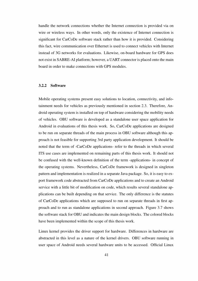
handle the network connections whether the Internet connection is provided via on
wire or wireless ways. In other words, only the existence of Internet connection is
significant for CarCoDe software stack rather than how it is provided. Considering
this fact, wire communication over Ethernet is used to connect vehicles with Internet
instead of 3G networks for evaluations. Likewise, on-board hardware for GPS does
not exist in SABRE-AI platform; however, a UART connector is placed onto the main
board in order to make connections with GPS modules.
3.2.2 Software
Mobile operating systems present easy solutions to location, connectivity, and info-
tainment needs for vehicles as previously mentioned in section 2.3. Therefore, An-
droid operating system is installed on top of hardware considering the mobility needs
of vehicles. OBU software is developed as a standalone user space application for
Android in evaluations of this thesis work. So, CarCoDe applications are designed
to be run on separate threads of the main process in OBU software although this ap-
proach is not feasible for supporting 3rd party application development. It should be
noted that the term of -CarCoDe applications- refer to the threads in which several
ITS use cases are implemented on remaining parts of this thesis work. It should not
be confused with the well-known definition of the term -applications- in concept of
the operating systems. Nevertheless, CarCoDe framework is designed in singleton
pattern and implementation is realized in a separate Java package. So, it is easy to ex-
port framework code abstracted from CarCoDe applications and to create an Android
service with a little bit of modification on code, which results several standalone ap-
plications can be built depending on that service. The only difference is the statutes
of CarCoDe applications which are supposed to run on separate threads in first ap-
proach and to run as standalone applications in second approach. Figure 3.7 shows
the software stack for OBU and indicates the main design blocks. The colored blocks
have been implemented within the scope of this thesis work.
Linux kernel provides the driver support for hardware. Differences in hardware are
abstracted in this level as a nature of the kernel drivers. OBU software running in
user space of Android needs several hardware units to be accessed. Official Linux
41
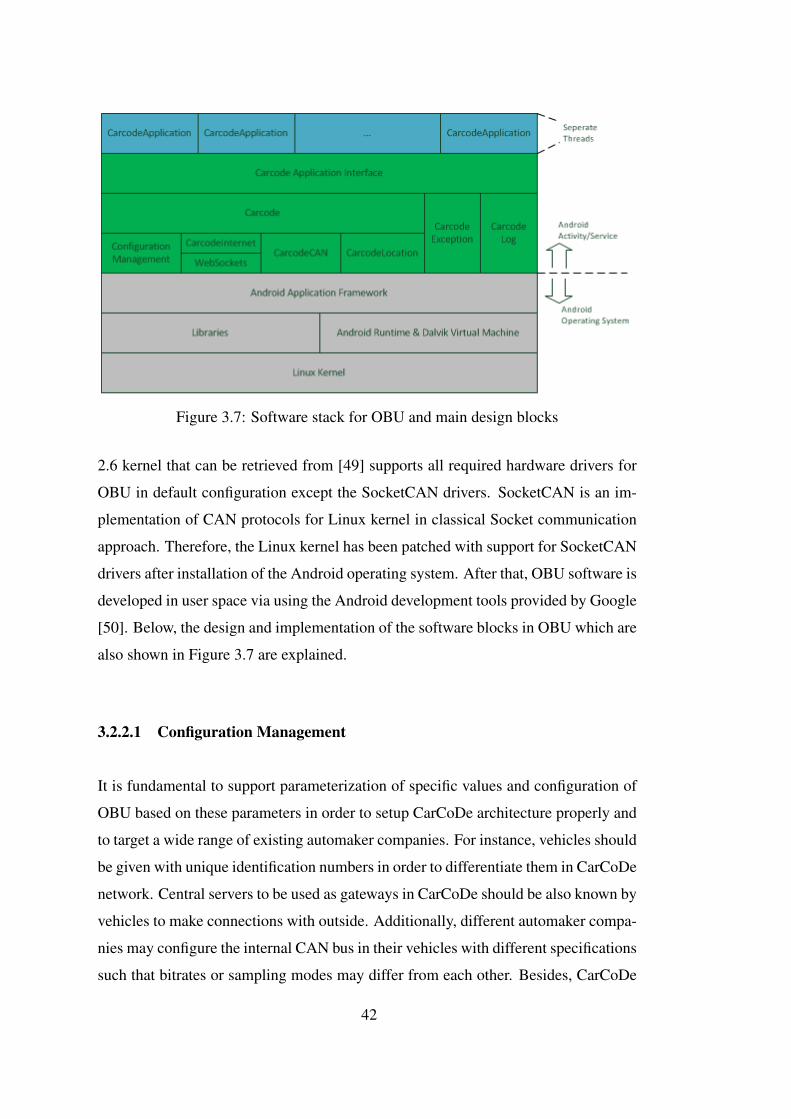
Figure 3.7: Software stack for OBU and main design blocks
2.6 kernel that can be retrieved from [49] supports all required hardware drivers for
OBU in default configuration except the SocketCAN drivers. SocketCAN is an im-
plementation of CAN protocols for Linux kernel in classical Socket communication
approach. Therefore, the Linux kernel has been patched with support for SocketCAN
drivers after installation of the Android operating system. After that, OBU software is
developed in user space via using the Android development tools provided by Google
[50]. Below, the design and implementation of the software blocks in OBU which are
also shown in Figure 3.7 are explained.
3.2.2.1 Configuration Management
It is fundamental to support parameterization of specific values and configuration of
OBU based on these parameters in order to setup CarCoDe architecture properly and
to target a wide range of existing automaker companies. For instance, vehicles should
be given with unique identification numbers in order to differentiate them in CarCoDe
network. Central servers to be used as gateways in CarCoDe should be also known by
vehicles to make connections with outside. Additionally, different automaker compa-
nies may configure the internal CAN bus in their vehicles with different specifications
such that bitrates or sampling modes may differ from each other. Besides, CarCoDe
42
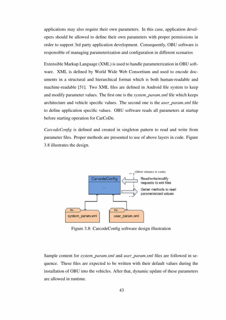
applications may also require their own parameters. In this case, application devel-
opers should be allowed to define their own parameters with proper permissions in
order to support 3rd party application development. Consequently, OBU software is
responsible of managing parameterization and configuration in different scenarios
Extensible Markup Language (XML) is used to handle parameterization in OBU soft-
ware. XML is defined by World Wide Web Consortium and used to encode doc-
uments in a structural and hierarchical format which is both human-readable and
machine-readable [51]. Two XML files are defined in Android file system to keep
and modify parameter values. The first one is the system_param.xml file which keeps
architecture and vehicle specific values. The second one is the user_param.xml file
to define application specific values. OBU software reads all parameters at startup
before starting operation for CarCoDe.
CarcodeConfig is defined and created in singleton pattern to read and write from
parameter files. Proper methods are presented to use of above layers in code. Figure
3.8 illustrates the design.
Figure 3.8: CarcodeConfig software design illustration
Sample content for system_param.xml and user_param.xml files are followed in se-
quence. These files are expected to be written with their default values during the
installation of OBU into the vehicles. After that, dynamic update of these parameters
are allowed in runtime.
43
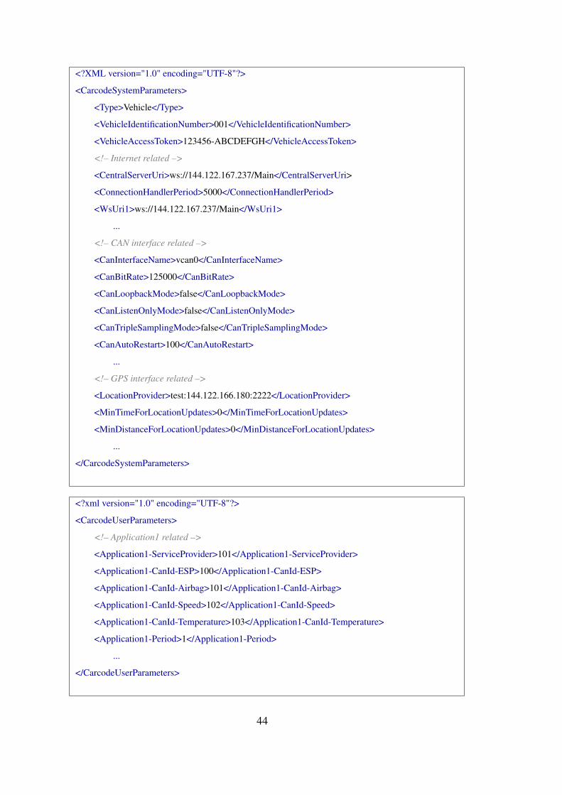
<?XML version="1.0" encoding="UTF-8"?>
<CarcodeSystemParameters>
<Type>Vehicle</Type>
<VehicleIdentificationNumber>001</VehicleIdentificationNumber>
<VehicleAccessToken>123456-ABCDEFGH</VehicleAccessToken>
<!– Internet related –>
<CentralServerUri>ws://144.122.167.237/Main</CentralServerUri>
<ConnectionHandlerPeriod>5000</ConnectionHandlerPeriod>
<WsUri1>ws://144.122.167.237/Main</WsUri1>
...
<!– CAN interface related –>
<CanInterfaceName>vcan0</CanInterfaceName>
<CanBitRate>125000</CanBitRate>
<CanLoopbackMode>false</CanLoopbackMode>
<CanListenOnlyMode>false</CanListenOnlyMode>
<CanTripleSamplingMode>false</CanTripleSamplingMode>
<CanAutoRestart>100</CanAutoRestart>
...
<!– GPS interface related –>
<LocationProvider>test:144.122.166.180:2222</LocationProvider>
<MinTimeForLocationUpdates>0</MinTimeForLocationUpdates>
<MinDistanceForLocationUpdates>0</MinDistanceForLocationUpdates>
...
</CarcodeSystemParameters>
<?xml version="1.0" encoding="UTF-8"?>
<CarcodeUserParameters>
<!– Application1 related –>
<Application1-ServiceProvider>101</Application1-ServiceProvider>
<Application1-CanId-ESP>100</Application1-CanId-ESP>
<Application1-CanId-Airbag>101</Application1-CanId-Airbag>
<Application1-CanId-Speed>102</Application1-CanId-Speed>
<Application1-CanId-Temperature>103</Application1-CanId-Temperature>
<Application1-Period>1</Application1-Period>
...
</CarcodeUserParameters>
44
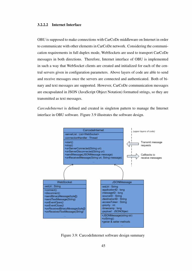
3.2.2.2 Internet Interface
OBU is supposed to make connections with CarCoDe middleware on Internet in order
to communicate with other elements in CarCoDe network. Considering the communi-
cation requirements in full duplex mode, WebSockets are used to transport CarCoDe
messages in both directions. Therefore, Internet interface of OBU is implemented
in such a way that WebSocket clients are created and initialized for each of the cen-
tral servers given in configuration parameters. Above layers of code are able to send
and receive messages once the servers are connected and authenticated. Both of bi-
nary and text messages are supported. However, CarCoDe communication messages
are encapsulated in JSON (JavaScript Object Notation) formatted strings, so they are
transmitted as text messages.
CarcodeInternet is defined and created in singleton pattern to manage the Internet
interface in OBU software. Figure 3.9 illustrates the software design.
Figure 3.9: CarcodeInternet software design summary
45
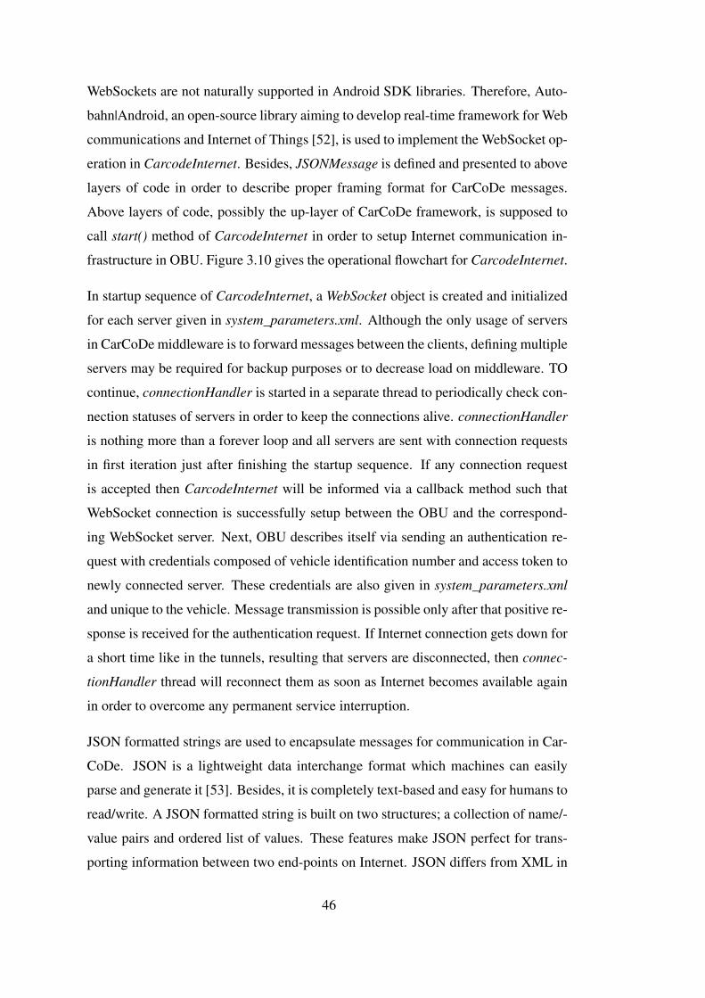
WebSockets are not naturally supported in Android SDK libraries. Therefore, Auto-
bahn|Android, an open-source library aiming to develop real-time framework for Web
communications and Internet of Things [52], is used to implement the WebSocket op-
eration in CarcodeInternet. Besides, JSONMessage is defined and presented to above
layers of code in order to describe proper framing format for CarCoDe messages.
Above layers of code, possibly the up-layer of CarCoDe framework, is supposed to
call start() method of CarcodeInternet in order to setup Internet communication in-
frastructure in OBU. Figure 3.10 gives the operational flowchart for CarcodeInternet.
In startup sequence of CarcodeInternet, a WebSocket object is created and initialized
for each server given in system_parameters.xml. Although the only usage of servers
in CarCoDe middleware is to forward messages between the clients, defining multiple
servers may be required for backup purposes or to decrease load on middleware. TO
continue, connectionHandler is started in a separate thread to periodically check con-
nection statuses of servers in order to keep the connections alive. connectionHandler
is nothing more than a forever loop and all servers are sent with connection requests
in first iteration just after finishing the startup sequence. If any connection request
is accepted then CarcodeInternet will be informed via a callback method such that
WebSocket connection is successfully setup between the OBU and the correspond-
ing WebSocket server. Next, OBU describes itself via sending an authentication re-
quest with credentials composed of vehicle identification number and access token to
newly connected server. These credentials are also given in system_parameters.xml
and unique to the vehicle. Message transmission is possible only after that positive re-
sponse is received for the authentication request. If Internet connection gets down for
a short time like in the tunnels, resulting that servers are disconnected, then connec-
tionHandler thread will reconnect them as soon as Internet becomes available again
in order to overcome any permanent service interruption.
JSON formatted strings are used to encapsulate messages for communication in Car-
CoDe. JSON is a lightweight data interchange format which machines can easily
parse and generate it [53]. Besides, it is completely text-based and easy for humans to
read/write. A JSON formatted string is built on two structures; a collection of name/-
value pairs and ordered list of values. These features make JSON perfect for trans-
porting information between two end-points on Internet. JSON differs from XML in
46
Figure 3.10: Operational flowchart for CarcodeInternet
47

such a way that it is simple and aims only to exchange data. Considering that ITS
applications mostly require data exchange between different end-points, CarCoDe
messages are designed to be sent in JSON format. However, some applications like
media streaming for infotainment purposes needs transmission of binary data with
lower overhead. In such cases, binary transmission methods of WebSocket objects
may be used instead of text-based and JSON formatted string messages.
JSONMessage is defined in order to describe CarCoDe message frames in CarcodeIn-
ternet. It presents proper methods to easily generate and parse JSON formatted strings
even for payload without spending any effort to conform with JSON syntax. It is
assumed that above layers of code pass messages to CarcodeInternet in JSONMes-
sage objects whose fields are completely filled. In transmit path, JSONMessage is
converted to string and sent to the corresponding server whose address is embed-
ded inside the message in order to be forwarded to the destination host. On receive
path, callback methods are defined. Received strings are converted to JSONMessage
objects and upper layers of code are informed about the newly received message.
Sample frame for CarCoDe messages has been given on Figure 3.4 in a generic format
which indicates fields as a must in order to setup proposed communication infrastruc-
ture. Here, previously given frame structure is extended such that additional fields are
added into the frame. Some of them are reserved for future use as extension to this
thesis work. However, they are still defined in current implementation. Following
fields exist in CarCoDe message frames which are implemented in OBU software.
• wsUri: Server URI address which the message will be sent to in middleware. It
is embedded inside the message in case of multiple server definitions. CarCoDe
applications running on top should not worry about this field. It is supposed to
be filled on upper layer of CarcodeInternet, possibly by the Carcode layer. If
multiple server addresses are to be defined then a smart algorithm should be
designed as future work in order to decide server address for the message. In
current implementation, it is assumed that applications know URI addresses of
the servers.
• applicationId: 64-bit identification number which indicates the application
that the message belongs to.
48

• messageId: 64-bit identification number which defines the message. Applica-
tion developers for CarCoDe are free to use desired values for their messages
belonging to their applications.
• sourceId: Own host identification number/string for OBU which is used to
differentiate it in CarCoDe network. By means of this field, receiver of the
message will know who is the sender.
• destinationId: Identification number/string for the destination host which the
message will be sent to. It can belong to any of service provider, roadside unit,
user device, or another vehicle in CarCoDe network.
• accessToken: Password to be embedded inside the messages in order to secure
communication. Servers in middleware are supposed to know corresponding
access tokens for each client and responsible of checking if they match with
the sender. In case of non-matching requests, message transmission should be
dropped in middleware.
• priority: Priority levels for messages. Application developers should be al-
lowed to define their own priority levels for their messages with restrictions
based on application types. For instance, any message belonging to infotain-
ment applications should never have greater priorities than the messages of
safety applications. This control mechanism is left as future work. Current
implementation allows all messages to be given with all priorities.
• timestamp 64-bit integer number which indicates the creation time for mes-
sages since EPOCH. It is embedded inside the message in case messages may
be meaningful only for a restricted time in some applications.
• payload: Meaningful part in messages which are to be processed by applica-
tions. It can contain many pairs to exchange data. Applications are free to fill
payload provided that JSON syntax is conformed with.
An example CarCoDe message in form of JSON formatted string is followed for
clearness.
49

{
"wsUri":"ws://testserver.com/Main",
"applicationId":10000001,
"messageId":101,
"sourceId":"1A2B3C4D5E6F7G8H9J",
"destinationId":"1Q2W3E4R5T6Y7U8I9O",
"accessToken":"123456789-ABCDEFGHJKLMN",
"priority":0,
"timestamp":1420918256766,
"payload":{
"speed":90,
"location":{
"latitude":32.6543,
"longitude":42.5492,
},
"temperature":18,
"request":"route"
}
}
3.2.2.3 CAN Interface
OBU has CAN (Controller Area Network) interface to communicate with in-vehicle
subsystems which makes it possible to collect real-time information about vehicles.
CAN bus is a message based protocol which is developed by Bosch [54]. Several
versions are published throughout today. The most commonly used one is the CAN
2.0 specification which has two parts; CAN 2.0a supports standard length of 11-bit
identifiers and CAN 2.0b supports extended length of 29-bit identifiers. Provided that
each node in CAN network has unique identifiers, message based communication oc-
curs among them such that the lowest identifier has the highest priority during the
arbitration of messages. Bitrates up to 1 Mbps are possible in CAN bus communica-
tions. However, CAN FD (CAN with Flexible Data-rate) was introduced recently by
Bosch in 2012 to overcome the Classic CAN’s bit rate limitation and to expand the
number of data bytes per CAN frame from up to 8 to up to 64 [55]. Currently, OBU
software supports standard length of identifiers with up to 8 bytes of data.
50
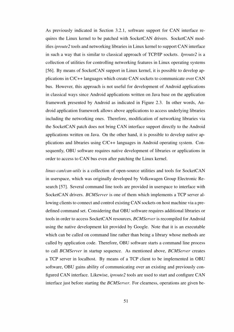
As previously indicated in Section 3.2.1, software support for CAN interface re-
quires the Linux kernel to be patched with SocketCAN drivers. SocketCAN mod-
ifies iproute2 tools and networking libraries in Linux kernel to support CAN interface
in such a way that is similar to classical approach of TCP/IP sockets. Iproute2 is a
collection of utilities for controlling networking features in Linux operating systems
[56]. By means of SocketCAN support in Linux kernel, it is possible to develop ap-
plications in C/C++ languages which create CAN sockets to communicate over CAN
bus. However, this approach is not useful for development of Android applications
in classical ways since Android applications written on Java base on the application
framework presented by Android as indicated in Figure 2.3. In other words, An-
droid application framework allows above applications to access underlying libraries
including the networking ones. Therefore, modification of networking libraries via
the SocketCAN patch does not bring CAN interface support directly to the Android
applications written on Java. On the other hand, it is possible to develop native ap-
plications and libraries using C/C++ languages in Android operating system. Con-
sequently, OBU software requires native development of libraries or applications in
order to access to CAN bus even after patching the Linux kernel.
linux-can/can-utils is a collection of open-source utilities and tools for SocketCAN
in userspace, which was originally developed by Volkswagen Group Electronic Re-
search [57]. Several command line tools are provided in userspace to interface with
SocketCAN drivers. BCMServer is one of them which implements a TCP server al-
lowing clients to connect and control existing CAN sockets on host machine via a pre-
defined command set. Considering that OBU software requires additional libraries or
tools in order to access SocketCAN resources, BCMServer is recompiled for Android
using the native development kit provided by Google. Note that it is an executable
which can be called on command line rather than being a library whose methods are
called by application code. Therefore, OBU software starts a command line process
to call BCMServer in startup sequence. As mentioned above, BCMServer creates
a TCP server in localhost. By means of a TCP client to be implemented in OBU
software, OBU gains ability of communicating over an existing and previously con-
figured CAN interface. Likewise, iproute2 tools are used to start and configure CAN
interface just before starting the BCMServer. For clearness, operations are given be-
51

low in sequence as to be an example for CAN bus access. Note that, OBU software
needs super-user permissions to realize all operations or it should be compiled with
the system signature for Android.
1. First of all, CAN interface is configured via calling following commands (iproute2
tools) in command line which can be realized in a subprocess started inside
OBU software. It is assumed that can0 is given as the name for CAN interface
to be controlled in system resources.
ip link set can0 type can bitrate 125000
ip link set can0 type can loopback off
ip link set can0 type can listen-only off
ip link set can0 type can triple-sampling on
ip link set can0 type can autorestart 100
2. can0 is started for operation via calling following command in command line
which can be realized in a subprocess started inside OBU software.
ip link set can0 up
3. BCMServer is started via calling following command in command line. Note
that BCMServer is placed into the following path in Android file system. Like-
wise, it starts in a subprocess inside OBU software.
/data/linux-can-utils/bcmserver
4. A TCP client is created in OBU software and connected to BCMServer in lo-
calhost in order to provide interprocess communication between them.
5. Following string is sent to BCMServer in order to send a single CAN frame
having an identifier of 0x123 and 2 bytes of data composed of 0x10 and 0x20.
< can0 S 0 0 123 2 10 20 >
6. Following string is sent to BCMServer in order to start a periodic transmission
of previous CAN frame in every 2 second.
< can0 A 2 0 123 2 10 20 >
7. Following string is sent to BCMServer in order to stop a previously started
periodic transmission.
< can0 D 0 0 123 0 >
52

8. Following string is sent to BCMServer in order to be notified whenever CAN
frames having identifier of 0x123 exist on CAN bus. In other words, frames
are registered to be listened. If the corresponding frame with given identifier is
detected on bus, BCMServer sends latter string to TCP client in order to inform
it including also the data bytes.
< can0 R 0 0 123 0 >
< can0 123 2 10 20 >
CarcodeCan is defined and implemented in singleton pattern to manage the CAN in-
terface in OBU software. Figure 3.11 illustrates the software design. Upper layers
of code is supposed to call start() method in CarcodeCan in order to setup required
infrastructure to access CAN bus. In startup sequence, OBU software checks whether
it can execute commands with root privileges, or not. Then, CAN interface is con-
figured and started based on the parameters read from CarcodeConfig as explained
above. BCMServer is started in a separate process and a TCPClient object is cre-
ated to connect it. OBU software is able to send and receive CAN frames once the
connection with BCMServer is successfully achieved.
Figure 3.11: CarcodeCan software design summary
53

CANMessage is defined in CarcodeCan in order to describe possible CAN frames
with one common structure. It presents proper methods to generate CAN frames
with standard length identifiers and at most 8 bytes of data. Above layers of code
are supposed to send transmit requests of CAN frames with CANMessage objects.
Likewise, CarcodeCan informs upper layers in same way for receive path.
3.2.2.4 Location Awareness
Location awareness is fundamental for development of a generic framework for ITS
applications considering the mobility of vehicles. Once the OBU is supported with
real time access of vehicle location on roads, it will be possible to implement location
based CarCoDe applications such as congestion aware navigation for efficient traf-
fic management, emergency accident detection systems for safety purposes, vehicle
tracking systems, etc. Accordingly, CarcodeLocation is designed and implemented
in OBU software in order to manage the location sources for above running CarCoDe
applications.
Android operating system presents a great software infrastructure to manage the loca-
tion sources in mobile devices. In Android application framework, android.location
library handles the location sources and fixes. There exist three different types of
location sources which are presented to be used in Android applications. These are
followed [58];
• GPS: Location is determined via using the satellites. An external GPS hard-
ware is required.
• network: Location is determined via using the cellular networks or WiFi access
points. A wireless network connection is required.
• passive: Location information is retrieved without actually initiating the re-
quest itself. This location source returns the last location information which
is requested by other applications on system. It can return locations generated
by other providers. In Android framework, it is implemented considering that
processing load will be very high due to the location fixes if more than one
application request location access.
54

Besides, Android presents mocking location data for test purposes without actually
having the hardware or realizing the movement between two points. KML (Keyhole
Markup Language) is a file format developed by Google in order to display geo-
graphic data in Earth. KML files are used to mock location movements in Android
application framework. So, it is possible to develop Android applications targeting
both of real and mocking location sources without actually changing the code. Con-
sidering this fact, a mocking location provider is used in evaluations of this thesis
work.
Figure 3.12 illustrates the software design for CarcodeLocation. In startup sequence,
upper layers of code, possibly the Carcode layer, is supposed to call start() method
of CarcodeLocation in order to setup underlying software infrastructure to access
location information. Name of the location provider, i.e., GPS, mocking, etc., and
minimum time/distance values to update location data are read from CarcodeCon-
fig. Then, android.location.LocationProvider and android.location.LocationListener
objects are created and initialized with given parameters. After that, Android starts
listening location updates. CarCoDe applications are allowed to request location data
manually, which returns the last calculated location fix. Additionally, a callback
method, onLocationUpdated(), is called if location changes in an amount of given
distance and time.
Figure 3.12: CarcodeLocation software design summary
It should be noted that Android assigns an UART port on hardware for communicat-
ing with external GPS devices in default installations. Most of the GPS devices/mod-
ules on market are designed as to be in plug & play form through UART port and they
55

send location data in well-known NMEA (National Marine Electronics Association)
format which Android can identify and understands the messages. Moreover, wireless
network connections are identified by network provider. Therefore, indicating name
of the location provider while initializing the android.location.LocationProvider ob-
ject is enough setup underlying software infrastructure in Android in order to provide
location awareness to the applications running above. In case of mocking the loca-
tion data for testing purposes, android.location presents proper methods to manually
input location information in code. Exploiting this feature, CarcodeLocation is de-
signed in such a way that it connects to a TCP server in local area network to get
location updates in a separate thread if location provider is indicated as mocking in
CarcodeConfig. So, a mocking location provider has been developed to send location
updates in NMEA format via using the KML files in evaluations part of this thesis
work.
3.2.2.5 Carcode Layer
Carcode layer, more explicitly CarCoDe Framework Up-Layer, is designed and im-
plemented in singleton pattern on top of CarcodeConfig, CarcodeInternet, Carcode-
Can and CarcodeLocation in order to manage and map them to the CarCoDe appli-
cations running above. Figure 3.13 illustrates the software design.
Carcode is supposed to be main entry point to start operation for CarCoDe archi-
tecture on host machine. Therefore, start() method is called first in order to initi-
ate the startup sequence. First of all, configuration settings and parameters are read
from files, system_parameters.xml and user_parameters.xml, via a call to Carcode-
Config.load(). After that, CarcodeLocation.start() is called in order to start location
services. Likewise, CAN bus and Internet interfaces are setup via calling correspond-
ing methods, CarcodeCan.start() and CarcodeInternet.start(). What happens in each
of them have been previously given in related sections. Finally, CarCoDe framework
becomes ready to give service to CarCoDe applications if all of the called methods
return with successive values.
As indicated in Section 3.2.2, OBU software has been developed as a standalone
Android application in scope of this thesis work. So, Carcode.start() method is ex-
56
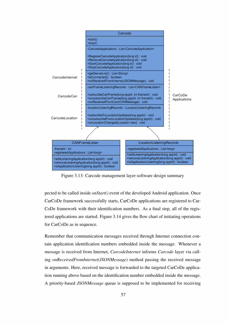
Figure 3.13: Carcode management layer software design summary
pected to be called inside onStart() event of the developed Android application. Once
CarCoDe framework successfully starts, CarCoDe applications are registered to Car-
CoDe framework with their identification numbers. As a final step, all of the regis-
tered applications are started. Figure 3.14 gives the flow chart of initiating operations
for CarCoDe as in sequence.
Remember that communication messages received through Internet connection con-
tain application identification numbers embedded inside the message. Whenever a
message is received from Internet, CarcodeInternet informs Carcode layer via call-
ing onReceivedFromInternet(JSONMessage) method passing the received message
in arguments. Here, received message is forwarded to the targeted CarCoDe applica-
tion running above based on the identification number embedded inside the message.
A priority-based JSONMessage queue is supposed to be implemented for receiving
57
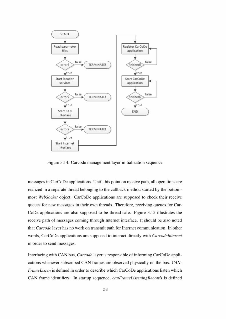
Figure 3.14: Carcode management layer initialization sequence
messages in CarCoDe applications. Until this point on receive path, all operations are
realized in a separate thread belonging to the callback method started by the bottom-
most WebSocket object. CarCoDe applications are supposed to check their receive
queues for new messages in their own threads. Therefore, receiving queues for Car-
CoDe applications are also supposed to be thread-safe. Figure 3.15 illustrates the
receive path of messages coming through Internet interface. It should be also noted
that Carcode layer has no work on transmit path for Internet communication. In other
words, CarCoDe applications are supposed to interact directly with CarcodeInternet
in order to send messages.
Interfacing with CAN bus, Carcode layer is responsible of informing CarCoDe appli-
cations whenever subscribed CAN frames are observed physically on the bus. CAN-
FrameListen is defined in order to describe which CarCoDe applications listen which
CAN frame identifiers. In startup sequence, canFrameListeningRecords is defined
58
Figure 3.15: Receive path for messages in Internet communication
as a list of CANFrameListen definition, which initially contains nothing. CarCoDe
applications are supposed to subscribe to these records with interested CAN frame
identifiers. It is allowed that more than one CarCoDe application may interest CAN
frames with the same identifier. Dynamic reconfiguration of the subscribed frames
is possible during runtime, i.e., an application may unsubscribe from listening CAN
frames whenever desired. Carcode sends required information to CarcodeCan in or-
der to start listening CAN frames if an identifier is not currently being listened at the
time of subscription request. Likewise, CarcodeCan stops listening the CAN frames
with specified identifier if there does not remain any interested CarCoDe application
for it at the time of unsubscription requests. Remember that CarcodeCan is informed
via a callback method if any of the interested CAN frames with specified identifiers
occur physically on the bus. Following that, an object in type of CANMessage is
constructed and passed to Carcode layer. Here, canFrameListeningRecords is looked
up with the frame identifier value and received CANMessage object is broadcasted
to the corresponding CarCoDe applications which are all subscribed. Priority based
and thread-safe CANMessage queues are supposed to be defined inside the CarCoDe
applications in order to receive messages. These operations for receive path in CAN
interface communication are illustrated in Figure 3.16. Similar to the Internet in-
terface communication, CarCoDe applications directly interacts with CarcodeCan in
order to send CAN frames, which means Carcode has no work on transmit path.
In like manner, another subscription approach is applied for CarCoDe applications
requiring location information during runtime. As indicated in Section 3.2.2.4, An-
droid’s location resources are used to get fixed location data from location providers.
CarcodeLocation is informed via a callback method if the location changes with a
59

Figure 3.16: Receive path for messages in CAN bus communication
given amount of distance. Static definition of the CarcodeLocation.lastLocation field
is updated on location changes and it is always open to use of CarCoDe applications
for manual requests. In case of desire to know as soon as the location is updated with a
new value, CarCoDe applications are supposed to subscribe their interests to Carcode
layer. Within the callback method for location updates, each subscribed CarCoDe ap-
plication will be informed with new location value in a separate thread of execution
owned by the callback method. In order to do this, a method is defined in interface,
i.e., base class, for CarCoDe applications which application developers are supposed
to override it for own usage.
It should be noted that priority message queues are used to pass received messages
from Carcode layer to CarCoDe applications for both of Internet and CAN interface
communications. However, it is also possible to override corresponding methods in
CarCoDe applications in case of desire to know as soon as new messages are received
so that they can be processed without any delaying of queue operation. By means
of this approach, it will be also possible to process received messages in CarCoDe
applications as independent of the priority values.
3.2.2.6 Interfacing with CarCoDe Applications
CarCoDe applications reside on top of CarCoDe framework which presents proper
methods and fields to them in order to access several resources for implementing dif-
ferent types of ITS use cases. So, reuse of the resources are supported via abstracting
CarCoDe applications from the underlying CarCoDe framework. This approach has
several benefits. For instance; many location-based ITS use cases can be realized by
60

having only one GPS sensor, or development of more than one CarCoDe application
which requires sniffing data from in-vehicle CAN bus is possible over a common
CAN hardware. Additionally, CarCoDe applications are designed in such a way that
they are executed concurrently without knowledge of each other. Therefore, newer
ITS use cases can be developed and integrated to vehicle without any change on re-
maining parts. This feature also provides the development of CarCoDe applications
by other developers as well.
Considering that OBU software is developed as a standalone Android application for
evaluations in scope of this thesis work, CarCoDe applications are designed to be
executed in separate threads. Therefore, Java class libraries are used in order for de-
velopment of the CarCoDe applications and to provide integration of them with the
main application of OBU software. In other words, CarCoDe applications are devel-
oped in own Java classes as class libraries which provides getting rid of recompiling
the OBU software each time whenever a new application is integrated. As indicated in
Figure 3.14, CarCoDe applications are registered to CarCoDe framework and started
for operation after the initialization operations belonging to the underlying resources
successively finish. In order to start for operation, CarCoDe applications are loaded
from corresponding class libraries just before the registration of them. Besides, the
information of which CarCoDe applications will run is requested from CarcodeCon-
fig since the list of CarCoDe applications to be run is supposed to be indicated in
system_parameters.xml file.
Accordingly, an abstract class definition which is to be extended in order to develop
CarCoDe applications is designed and partially implemented in order to interface with
underlying CarCoDe framework. It contains method definitions and fields required
as a must for implementation. Besides, it extends the Runnable definition in Android
so that CarCoDe applications are executed in own threads. Figure 3.17 gives the
summary of software design for CarcodeApplication abstract class. How to develop
CarCoDe applications via extending the given definition of CarcodeApplication is
explained on next section.
61
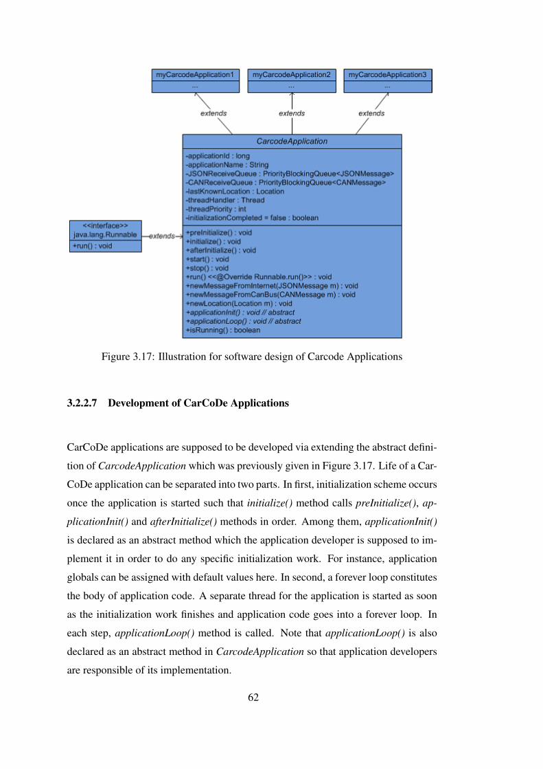
Figure 3.17: Illustration for software design of Carcode Applications
3.2.2.7 Development of CarCoDe Applications
CarCoDe applications are supposed to be developed via extending the abstract defini-
tion of CarcodeApplication which was previously given in Figure 3.17. Life of a Car-
CoDe application can be separated into two parts. In first, initialization scheme occurs
once the application is started such that initialize() method calls preInitialize(), ap-
plicationInit() and afterInitialize() methods in order. Among them, applicationInit()
is declared as an abstract method which the application developer is supposed to im-
plement it in order to do any specific initialization work. For instance, application
globals can be assigned with default values here. In second, a forever loop constitutes
the body of application code. A separate thread for the application is started as soon
as the initialization work finishes and application code goes into a forever loop. In
each step, applicationLoop() method is called. Note that applicationLoop() is also
declared as an abstract method in CarcodeApplication so that application developers
are responsible of its implementation.
62
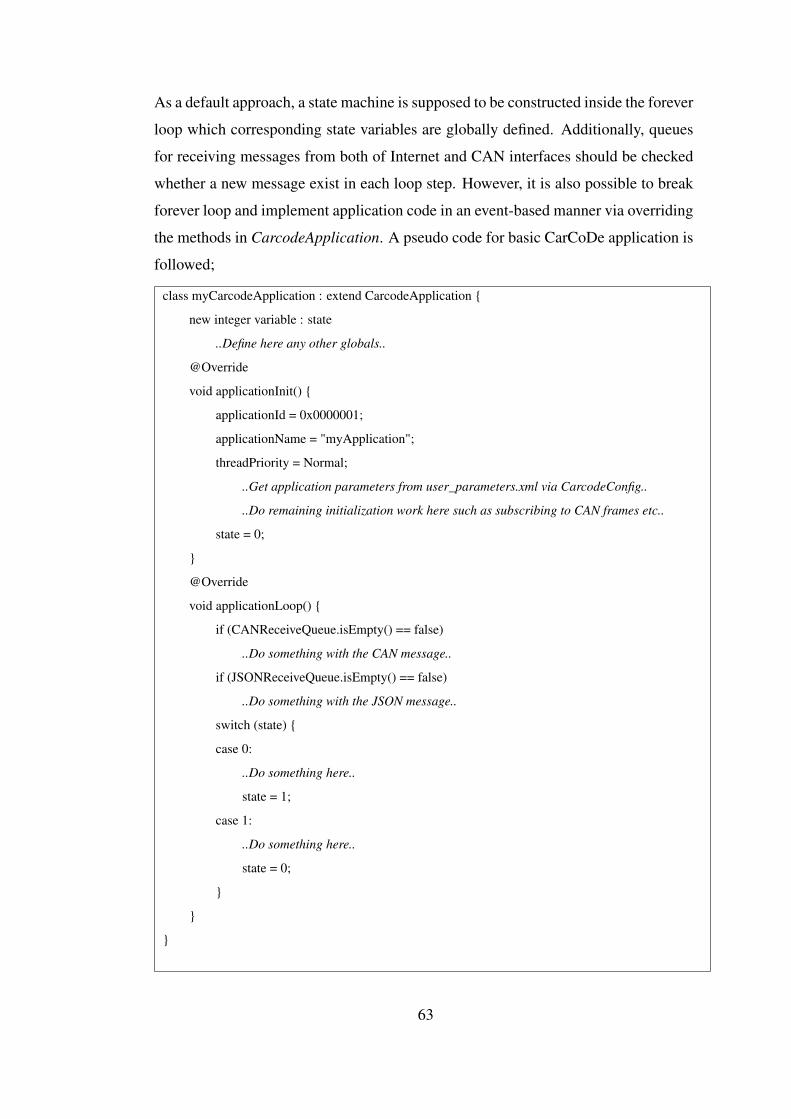
As a default approach, a state machine is supposed to be constructed inside the forever
loop which corresponding state variables are globally defined. Additionally, queues
for receiving messages from both of Internet and CAN interfaces should be checked
whether a new message exist in each loop step. However, it is also possible to break
forever loop and implement application code in an event-based manner via overriding
the methods in CarcodeApplication. A pseudo code for basic CarCoDe application is
followed;
class myCarcodeApplication : extend CarcodeApplication {
new integer variable : state
..Define here any other globals..
@Override
void applicationInit() {
applicationId = 0x0000001;
applicationName = "myApplication";
threadPriority = Normal;
..Get application parameters from user_parameters.xml via CarcodeConfig..
..Do remaining initialization work here such as subscribing to CAN frames etc..
state = 0;
}
@Override
void applicationLoop() {
if (CANReceiveQueue.isEmpty() == false)
..Do something with the CAN message..
if (JSONReceiveQueue.isEmpty() == false)
..Do something with the JSON message..
switch (state) {
case 0:
..Do something here..
state = 1;
case 1:
..Do something here..
state = 0;
}
}
}
63

64
CHAPTER 4
EVALUATIONS
4.1 Development of a Sample CarCoDe Application: Icy Roads Early Warning
System
• Icy Roads Early Warning System (IREWS) application is developed in order to
show all designed software blocks for OBU and communication rules in Car-
CoDe architecture work correctly as intended. Note that implementation of
OBU software may not be completely tested in all aspects via the IREWS ap-
plication; however, it verifies the proposed design rules, i.e. abstraction of ap-
plication code, and the proposed relationships between software design blocks.
• IREWS is developed on top of CarCoDe framework in a different Java pack-
age demonstrating the abstraction of application code from underlying resource
management modules.
• IREWS receives data from the messages on the CAN Bus, from the GPS Sen-
sor and sends data on the 3G interface to a remote server demonstrating the
resource management modules on CarCoDe regarding the CAN bus and GPS
resources on the vehicle as well as the communication features.
• A central server as middleware, a service provider for IREWS and tools for
simulating vehicle actions are developed for testing purposes based on the Car-
CoDe architecture definitions.
Vehicles skid on icy surfaces. In order to improve a vehicle’s stability by detecting and
reducing loss of traction, i.e. skidding, current vehicles are equipped with an internal
65

subsystem called as ESP (Electronic Stability Program). It works in autonomous way
that may become active and passive during runtime. OBU is connected to the vehicle
CAN Bus and can be programmed to listen any specific CAN messages that are sent
by the vehicle ECUs. In IREWS application, OBU listens to the ESP activation mes-
sages on the CAN Bus. It is assumed that a CAN frame identifier with one byte of data
is assigned to indicate the ESP status in a vehicle. Every time an ESP activation mes-
sage is detected on the CAN Bus, IREWS informs the application service provider
with the exact vehicle coordinates collected from the GPS sensor on the OBU and the
outside air temperature that is measured by the sensor on the vehicle and transmitted
on the CAN Bus. A service provider should provide IREWS application. To this end,
the service provider side of IREWS should be installed on a remote computer that
processes the received messages from vehicles such that icy roads are marked via the
coordinates and temperature information based on some algorithm. Furthermore, all
vehicles that are running the IREWS application update their absolute location infor-
mation periodically in order of seconds and inform the service provider by sending
messages through the CarCoDe network. Hence, the service provider knows about
the vehicles and icy regions so that it can send warning messages to those vehicles
approaching to the icy regions.
Accordingly, sample implementations for CarCoDe middleware and application ser-
vice provider are required in order to run this application. So, a central server has
been developed in order to forward messages between the connected clients. Addi-
tionally, the service provider of application has been developed in a very simple way
such that if ESP becomes active in a vehicle while the outside temperature is below
4 Celsius degrees then the current coordinates are marked as icy without processing
any additional data. Surely, this approach is not feasible to be applied in real life in
which improved filtering of received data from vehicles and processing of additional
data fields such as speed, acceleration, braking, etc. may involve on detection of icy
regions.
A virtual CAN bus has been created and used for realization of IREWS. Remember
that SocketCAN provides the CAN interface support in kernel space as described in
Section 3.2.2.1. Above running applications create and open a CAN socket in user
space in order to read from and write to a CAN bus. SocketCAN drivers provide
66

virtual CAN sockets which loopbacks the CAN data in kernel space just before ac-
cessing to the wire. Hence, it is identical to the user space applications above as of the
CAN frames are physically on the bus. We note that, virtual CAN bus differs from
physical CAN bus as no arbitration occurs in virtual sockets. We assume that the nec-
essary CAN ID assignment is carried out to ensure the timely response from CAN bus
as required. Furthermore, BCMServer is used to interface with SocketCAN drivers in
Android user space as previously indicated, which instantiates a TCP server in order
to bridge existing CAN interfaces with the TCP clients to be implemented. As to
remember here for a better insight, CarcodeCan in OBU software starts BCMServer
in a separate process and creates a TCP client in order to connect it in localhost. After
that, ASCII messages are used to send or receive CAN frames through the TCP con-
nection which provides the interprocess communication in OBU software. Likewise,
same approach may be applied in order to create simulations of vehicle hardware on
virtual CAN buses. So, the vehicle is simulated via a software developed in PC which
is supposed to connect BCMServer running on OBU. Additional tools are also pro-
vided in order to monitor CAN frames and send thrash of CAN data to virtual CAN
bus for experimental setup.
The current hardware platform does not have an on-board GPS support. However, An-
droid location resources provide mocking of location data and CarCoDe applications
are designed to use of Android location providers. So, a mocking location provider
has been introduced to update location information stored in android.location. In
order to do this, another TCP connection is setup between the vehicle simulation
software running on PC and the OBU software for experimental setup in evaluations.
Similar to the virtual CAN buses, mocking location providers are also same in view-
point of the above running applications. KML files are used to input route information
in order to mock location updates.
Below, the experimental setup is given first and the test scenario is described. Then,
development process of application is explained and the related discussions are finally
given.
67
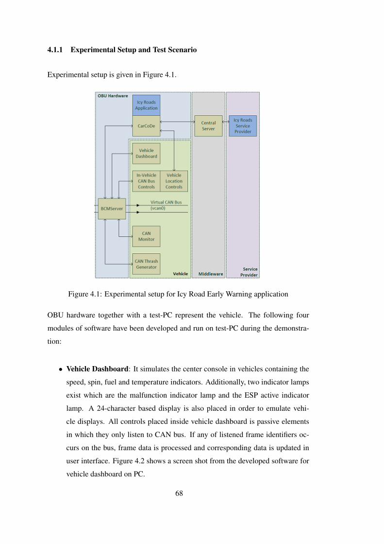
4.1.1 Experimental Setup and Test Scenario
Experimental setup is given in Figure 4.1.
Figure 4.1: Experimental setup for Icy Road Early Warning application
OBU hardware together with a test-PC represent the vehicle. The following four
modules of software have been developed and run on test-PC during the demonstra-
tion:
• Vehicle Dashboard: It simulates the center console in vehicles containing the
speed, spin, fuel and temperature indicators. Additionally, two indicator lamps
exist which are the malfunction indicator lamp and the ESP active indicator
lamp. A 24-character based display is also placed in order to emulate vehi-
cle displays. All controls placed inside vehicle dashboard is passive elements
in which they only listen to CAN bus. If any of listened frame identifiers oc-
curs on the bus, frame data is processed and corresponding data is updated in
user interface. Figure 4.2 shows a screen shot from the developed software for
vehicle dashboard on PC.
68

• Vehicle Simulator: This software is used in order to simulate vehicle actions
via a user interface. It has two parts. The first part is responsible for in-vehicle
CAN bus controls. These controls are active which means they write to CAN
bus with data bytes read from user controls for display. There exist controls
for speed, spin, fuel, temperature, indicator lamps and display. For instance,
increasing the speed value on corresponding user control element in user inter-
face simulates the speeding up of the vehicle. The second part is responsible
for vehicle location controls. Two options are presented. In the manual op-
tion, user can input the coordinate values manually. In KML file option, user is
supposed to input a KML file indicating the route for vehicle. Whenever the ab-
solute location changes, OBU software will be informed with new coordinates
in NMEA format. In viewpoint of OBU software, this location simulator does
not differ any compared to an external GPS module since they both send loca-
tion information in NMEA. Figure 4.3 shows a screen shot from the developed
software for vehicle simulator on PC.
• CANMonitor: This tool is used to monitor existing CAN frames on the con-
nected virtual CAN bus. It is a command line tool and it registers to all possible
1024 identifiers in CAN frames with standard length of 11-bit identifier. Figure
4.4 shows a screen shot from the developed software for CAN monitor.
• CANThrash: This tool is used to send background (thrash) CAN data to virtual
CAN bus. Note that nine different CAN frame identifiers are reserved in this
demonstration. This tool writes to CAN bus in random times with random data
bytes having remaining identifier values for CAN frames.
Following CAN identifiers and framing are assumed for above-mentioned vehicle
controls; (CAN Frame format: {ID|A|B|C|D|E|F|G|H} in which A..H are the 8 bytes
of data)
• speed: Identifier: 0x0D, Data length: 1, Frame: {0D|A}
value = A
*OBDII compatible
• spin: Identifier: 0x0C, Data length: 2, Frame: {0C|A|B}
69

value = ((A*256)+B)/4
*OBDII compatible
• fuel: Identifier: 0x09, Data length: 1, Frame: {09|A}
value = (A-128)*100/128
*OBDII compatible
• temperature: Identifier: 0x46, Data length: 1, Frame: {46|A}
value = A-40
*OBDII compatible
• malfunction indicator lamp: Identifier: 0x90, Data length: 1, Frame: {90|A}
value = A(7)
• esp lamp: Identifier: 0x91, Data length: 1, Frame: {91|A}
value = A(7)
• display(0..7): Identifier: 0x100, Data length: 1, Frame: {100|A|B|C|D|E|F|G|H}
value = A..H
• display(8..15): Identifier: 0x101, Data length: 1, Frame: {101|A|B|C|D|E|F|G|H}
value = A..H
• display(16..23): Identifier: 0x102, Data length: 1, Frame: {102|A|B|C|D|E|F|G|H}
value = A..H
Figure 4.2: Screenshot from developed software for vehicle dashboard on PC
70
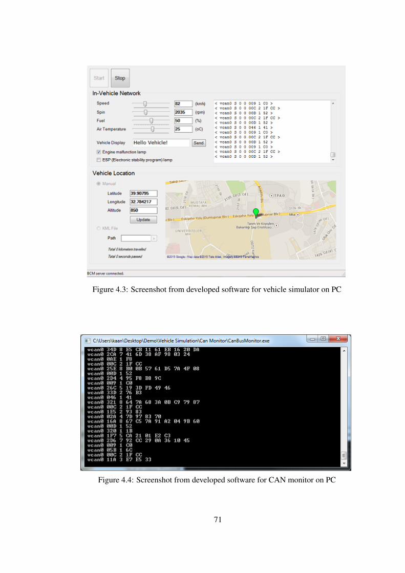
Figure 4.3: Screenshot from developed software for vehicle simulator on PC
Figure 4.4: Screenshot from developed software for CAN monitor on PC
71

A sample central server has been developed in PC in order to forward messages be-
tween the vehicle and the service provider for demonstration. Figure 4.5 shows a
screen shot from the developed software for central server acting as middleware.
Figure 4.5: Screen shot from developed software for central server acting as middle-
ware on PC
The service provider for Icy Road Early Warning application has been developed in
PC. Figure 4.6 shows a screen shot from the developed software during the demon-
strations.
For the demonstration of IREWS application, the vehicle is simulated such that it
starts movement from ODTU A1 Gate (32.78424, 39.9080022) to Kizilay (32.8542438,
39.9208382) with variable speed, spin and fuel values. In OBU configuration files,
the application is indicated as to start execution with CarCoDe.
1. In the first experiment, the air temperature is set to 25 Celsius degrees and
simulation started such that ESP never activated. It is supposed to be observed
in service provider application’s screen such that vehicle is tracked in real time
successfully during the trip.
2. In the second experiment, the air temperature is set to 25 Celsius degrees and
simulation started such that ESP activated at (32.79499,39.90897) for 2 sec-
onds. It is supposed to be observed in service provider application’s screen
such that no point is indicated as icy even the ESP signal is activated.
72

Figure 4.6: Screen shot from developed software for service provider of Icy Road
Early Warning application on PC
3. In third experiment, the air temperature is set to 0 Celsius degrees and sim-
ulation started such that ESP activated at (32.79499,39.90897) for 2 seconds.
After the vehicle reaches to destination point, identification number belonging
to vehicle is changed to another value as to be second vehicle distinct from pre-
vious one. The same route is simulated again. It is supposed to be observed in
service provider application’s screen such that a range of points are indicated
as icy while the ESP signal is activated for the first vehicle’s route. After that,
the second vehicle is supposed to get a warning message displayed on vehicle
dashboard while passing the icy section of route.
4.1.2 Development
Two different instances of IREWS application are developed. The first is executed on
OBU as a separate thread inside the main application of OBU software. The second is
executed on PC acting as service provider which has been developed as a standalone
executable for demonstrations. Since the scope of this thesis work contains only the
development of CarCoDe applications on OBU over proposed software stack, i.e.,
73
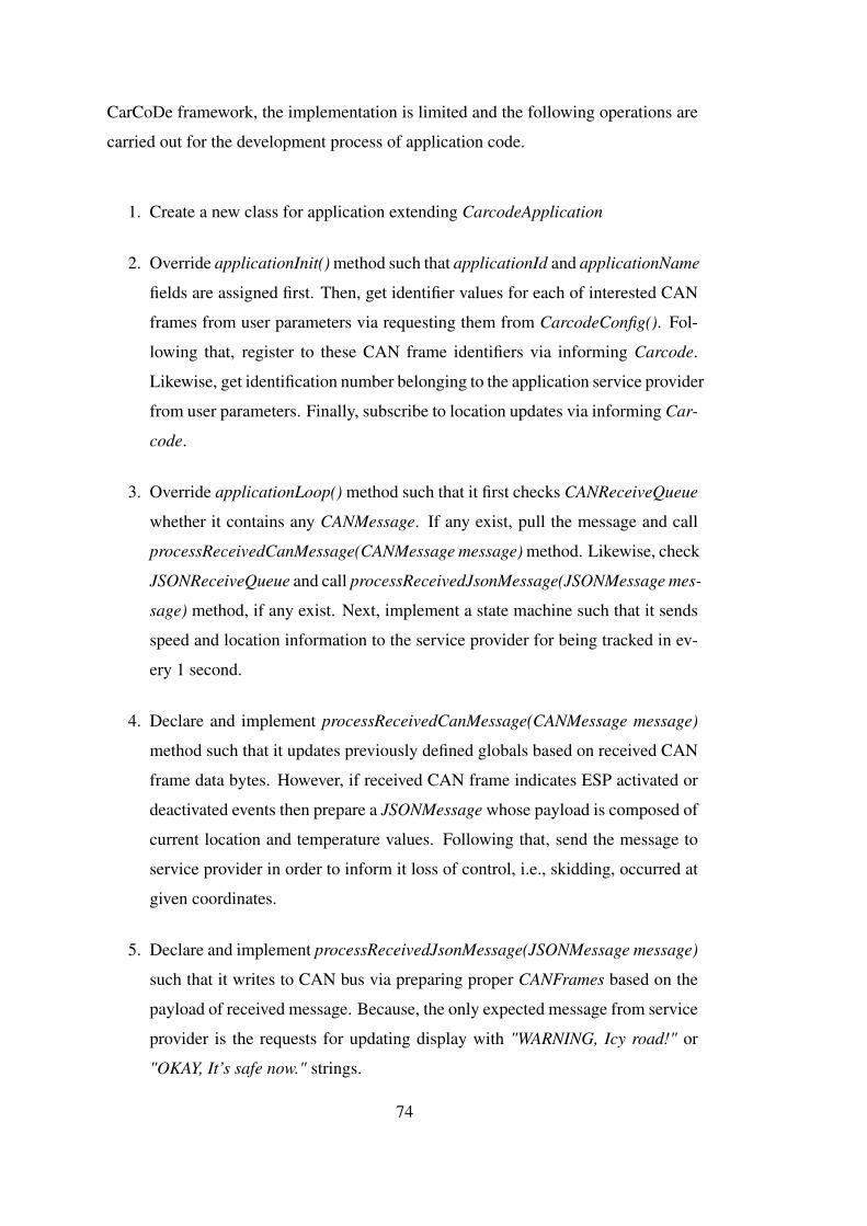
CarCoDe framework, the implementation is limited and the following operations are
carried out for the development process of application code.
1. Create a new class for application extending CarcodeApplication
2. Override applicationInit() method such that applicationId and applicationName
fields are assigned first. Then, get identifier values for each of interested CAN
frames from user parameters via requesting them from CarcodeConfig(). Fol-
lowing that, register to these CAN frame identifiers via informing Carcode.
Likewise, get identification number belonging to the application service provider
from user parameters. Finally, subscribe to location updates via informing Car-
code.
3. Override applicationLoop() method such that it first checks CANReceiveQueue
whether it contains any CANMessage. If any exist, pull the message and call
processReceivedCanMessage(CANMessage message) method. Likewise, check
JSONReceiveQueue and call processReceivedJsonMessage(JSONMessage mes-
sage) method, if any exist. Next, implement a state machine such that it sends
speed and location information to the service provider for being tracked in ev-
ery 1 second.
4. Declare and implement processReceivedCanMessage(CANMessage message)
method such that it updates previously defined globals based on received CAN
frame data bytes. However, if received CAN frame indicates ESP activated or
deactivated events then prepare a JSONMessage whose payload is composed of
current location and temperature values. Following that, send the message to
service provider in order to inform it loss of control, i.e., skidding, occurred at
given coordinates.
5. Declare and implement processReceivedJsonMessage(JSONMessage message)
such that it writes to CAN bus via preparing proper CANFrames based on the
payload of received message. Because, the only expected message from service
provider is the requests for updating display with "WARNING, Icy road!" or
"OKAY, It’s safe now." strings.
74
After creating the application class, it is compiled as a class library, and required
entries should be added to parameter files in order for application to be registered and
started with Carcode at startup.
4.1.3 Results and Discussions
IREWS is a simple application that can demonstrate that the design and the imple-
mentation of OBU realizes the intended operation. All software blocks previously
shown in Figure 3.7 are used during runtime of the application. Discussions are pre-
sented below for each software block and interfaces.
First of all, deployed IREWS application is not restricted in any manner by means
of parametrization via CarcodeConfig. For instance, different vehicle manufactur-
ers may be targeted with only one implementation and installed service provider.
The only action required is to update parameter files with corresponding CAN frame
identifiers for each vehicle manufactured by different companies in this application.
Consequently, CarCoDe applications can be developed in universal forms with proper
implementation and parameterization in application code.
Deployed IREWS application is able to communicate in full-duplex mode over Inter-
net network via the WebSocket implementation. Note that, application development
process does not include any initialization scheme nor connection requests. CarCoDe
applications are able to send and receive messages as soon as the execution begins.
This is because underlying CarCoDe framework provides the integrity of architec-
ture provided that Internet connection is available. In case of interruptions on Inter-
net connection like entering into a tunnel with vehicle, CarcodeInternet periodically
checks whether the connection becomes available again in order to re-provide the
integrity without any action. Besides, related fields such as WebSocket server ad-
dresses are also parameterized in order to support portability of architecture between
the different host machines. CarCoDe applications are supposed to know identifi-
cation numbers of destination clients in order to send messages to them. The types
of clients, i.e., vehicles, RSUs, service providers, etc., involving into communication
do not matter in viewpoint of architecture. Likewise, range of the communication is
neither significant. Because, CarCoDe provides communication between the clients
75

over a 3rd node, which is the middleware, via giving unique identification numbers
to them. Consequently, simple and unique way of communication is provided for
each type of client among the architecture. However, this approach yields short range
communications are suffered with higher latencies due to the middleware on com-
munication path. So, CarCoDe architecture, in current state of the art, aims to give
service to ITS applications having flexible timing requirements like in order of sec-
onds. Another drawback is that applications should know the absolute destination
identification numbers in order to send messages to them. A possible future work is
that implementation of loosely coupled (Publish and Subscribe) messaging scheme
may provide grouping of the clients via a keyword, location-based, etc. Moreover,
layered design approach may cause additional overheads and latencies for commu-
nication in default approach; however, CarCoDe applications are able to override
required methods of WebSockets in order to get rid of them.
IREWS on OBU begins listening to a the relevant different CAN frame identifiers
as soon as the application begins execution. It can write to CAN bus via prepar-
ing the frame and calling proper methods presented by CarCoDe framework. Sim-
ilar to the Internet interface, CarCoDe applications do not require any initialization
scheme for CAN interface since the underlying framework does. Besides, it is possi-
ble that concurrent applications may register listening CAN frames with same iden-
tifiers by means of canFrameListeningRecords table kept in Carcode over the same
CAN socket created by SocketCAN Although the current demonstration does not in-
clude concurrent execution of multiple applications, CANMessages are delivered to
the Icy Road Early Warning application via the forwarding mechanism implemented
in Carcode which is designed to support multiple applications. The drawback for
CAN in CarCoDe is that neither the CAN 2.0b data frames with extended length
identifiers nor the CAN request frames are supported in current implementation.
IREWS application is designed and implemented as location-aware such that it is in-
formed via a callback method whenever the location is updated in underlying frame-
work. Application developers are allowed to override this callback method in order to
implement location-triggered ITS applications such as advertising on roads. On the
other hand, CarCoDe applications are still able to request last known location infor-
mation form CarCoDe framework even if they are not subscribed to location updates.
76
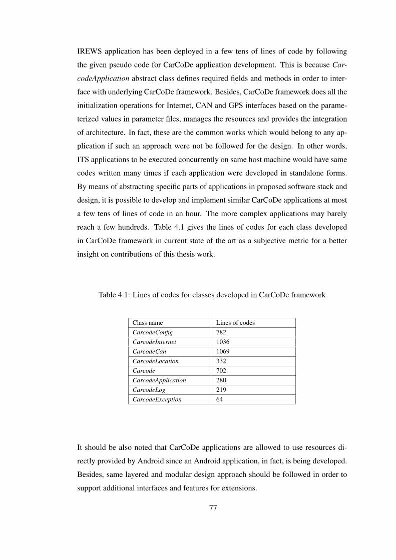
IREWS application has been deployed in a few tens of lines of code by following
the given pseudo code for CarCoDe application development. This is because Car-
codeApplication abstract class defines required fields and methods in order to inter-
face with underlying CarCoDe framework. Besides, CarCoDe framework does all the
initialization operations for Internet, CAN and GPS interfaces based on the parame-
terized values in parameter files, manages the resources and provides the integration
of architecture. In fact, these are the common works which would belong to any ap-
plication if such an approach were not be followed for the design. In other words,
ITS applications to be executed concurrently on same host machine would have same
codes written many times if each application were developed in standalone forms.
By means of abstracting specific parts of applications in proposed software stack and
design, it is possible to develop and implement similar CarCoDe applications at most
a few tens of lines of code in an hour. The more complex applications may barely
reach a few hundreds. Table 4.1 gives the lines of codes for each class developed
in CarCoDe framework in current state of the art as a subjective metric for a better
insight on contributions of this thesis work.
Table 4.1: Lines of codes for classes developed in CarCoDe framework
Class name Lines of codesCarcodeConfig 782CarcodeInternet 1036CarcodeCan 1069CarcodeLocation 332Carcode 702CarcodeApplication 280CarcodeLog 219CarcodeException 64
It should be also noted that CarCoDe applications are allowed to use resources di-
rectly provided by Android since an Android application, in fact, is being developed.
Besides, same layered and modular design approach should be followed in order to
support additional interfaces and features for extensions.
77

4.2 Evaluations on Communication Between Application Instances
• This section aims to demonstrate that CarCoDe is able to give support to ITS
applications with flexible timing requirements in order of seconds as intended.
In demonstrations, latency measurements are realized for communication via
the WebSockets.
CarCoDe applications are supposed to be executed distributedly over different client
host machines, i.e., vehicles, service providers, etc., and they are supposed to commu-
nicate with each other via WebSockets in the Internet network. In order to evaluate
communication between the clients, a different WebSocket server is used such that
messages will be echoed back instead of forwarding them based on the destination
identification numbers. So, an application will receive back the transmitted mes-
sage after a while. A CarCoDe application is developed for testing purposes such
that it sends dummy messages to an echo server in order to measure round trip time
of transmitted messages via taking two timestamps; just before sending the message,
just after receiving the message. It is reasonable that measured round trip times can be
considered as the latencies on message transmissions between the clients. Note that
timestamps are taken at the application level which means latency values caused by
the layered design of CarCoDe software stack are also considered in measurements.
• Case1:
– OBU and echo server resides on the same local area network with 100
Mbps connection speed.
– A single test application runs on OBU.
– Total of 100 message transmission requests are sent at once.
The measured latency values for 100 experiments are given and plotted in
Figure-4.7. Statistically calculated intervals for true mean values are followed
in Table-4.2. Measured mean value of 12.06 ms resides within +/- 0.16% of
the true mean value with a confidence level of 95% and within +/- 0.21% of the
true mean value with a confidence level of 99%. This latency is mostly caused
by processing delays in both directions. These processing delays include the
78
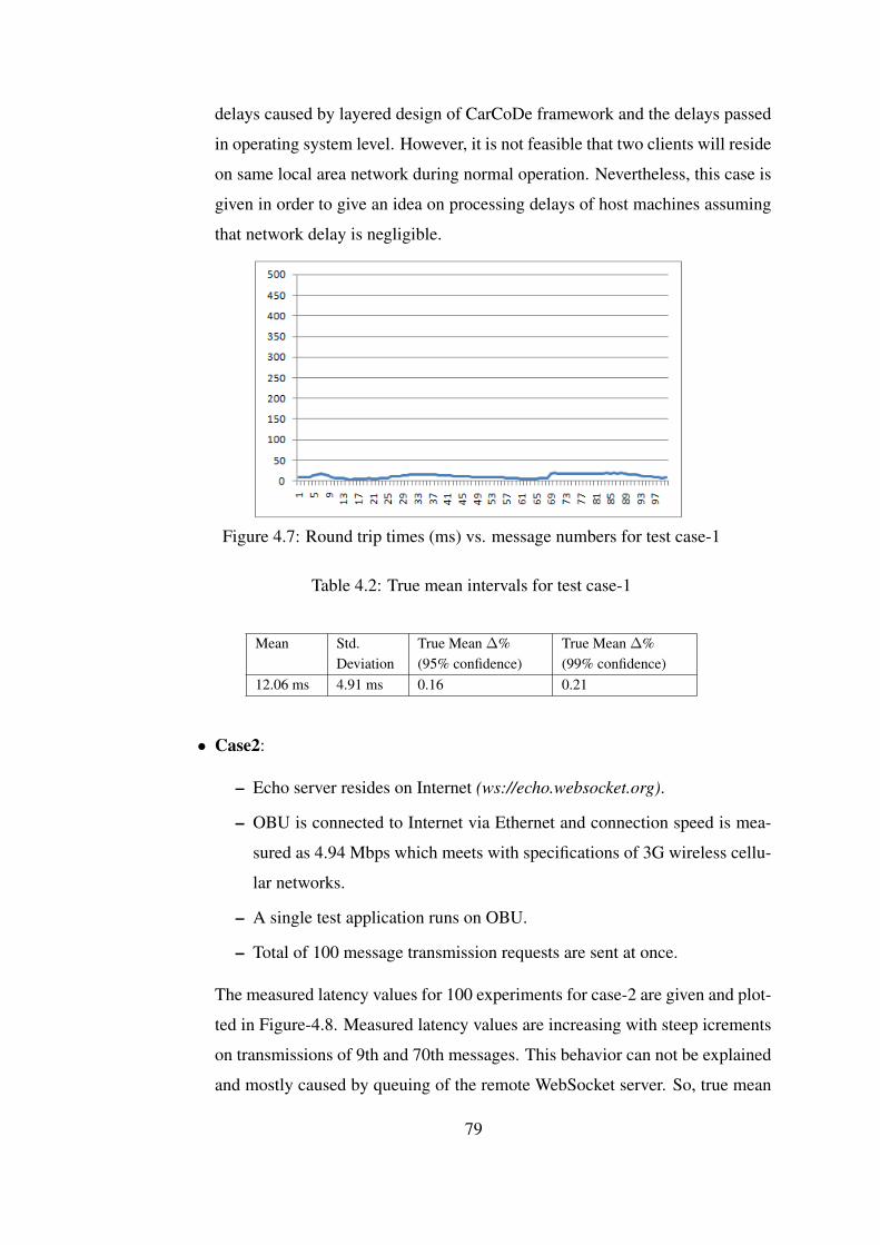
delays caused by layered design of CarCoDe framework and the delays passed
in operating system level. However, it is not feasible that two clients will reside
on same local area network during normal operation. Nevertheless, this case is
given in order to give an idea on processing delays of host machines assuming
that network delay is negligible.
Figure 4.7: Round trip times (ms) vs. message numbers for test case-1
Table 4.2: True mean intervals for test case-1
Mean Std.Deviation
True Mean ∆%(95% confidence)
True Mean ∆%(99% confidence)
12.06 ms 4.91 ms 0.16 0.21
• Case2:
– Echo server resides on Internet (ws://echo.websocket.org).
– OBU is connected to Internet via Ethernet and connection speed is mea-
sured as 4.94 Mbps which meets with specifications of 3G wireless cellu-
lar networks.
– A single test application runs on OBU.
– Total of 100 message transmission requests are sent at once.
The measured latency values for 100 experiments for case-2 are given and plot-
ted in Figure-4.8. Measured latency values are increasing with steep icrements
on transmissions of 9th and 70th messages. This behavior can not be explained
and mostly caused by queuing of the remote WebSocket server. So, true mean
79
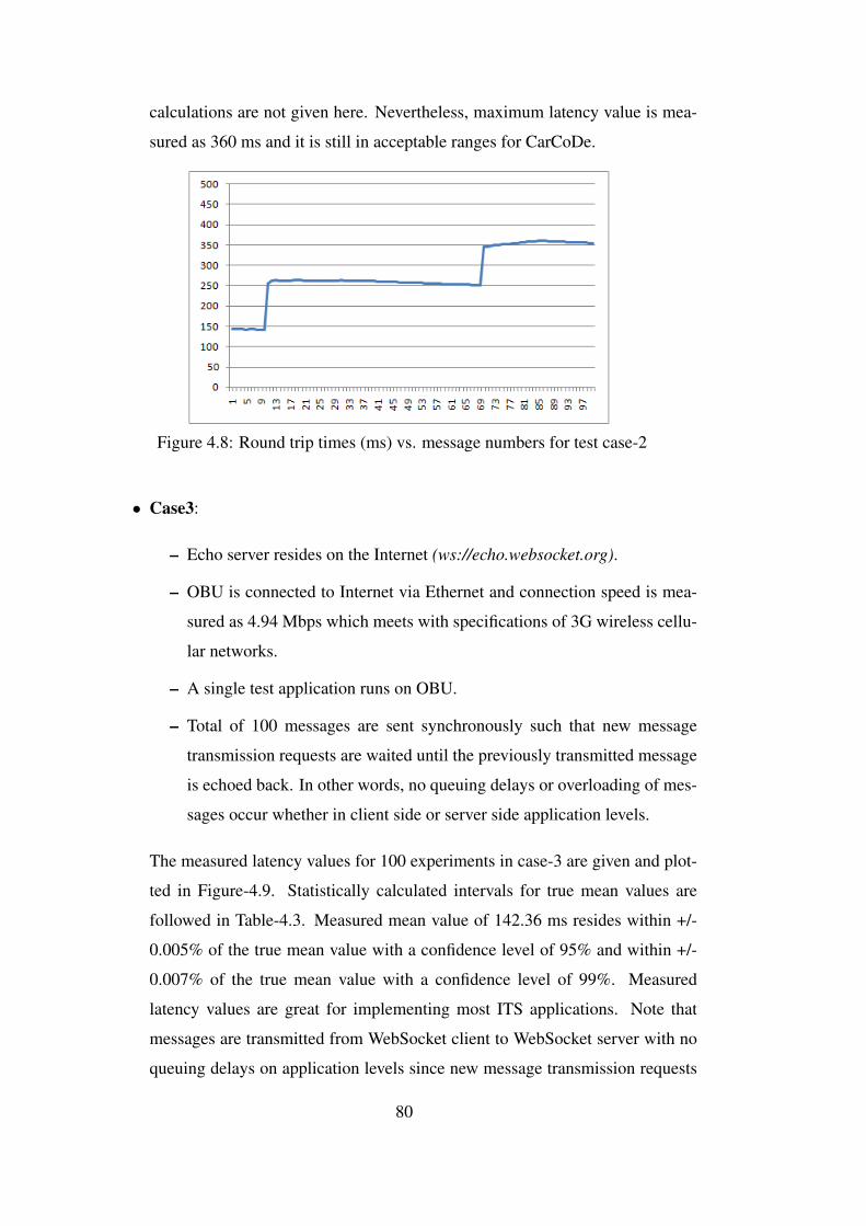
calculations are not given here. Nevertheless, maximum latency value is mea-
sured as 360 ms and it is still in acceptable ranges for CarCoDe.
Figure 4.8: Round trip times (ms) vs. message numbers for test case-2
• Case3:
– Echo server resides on the Internet (ws://echo.websocket.org).
– OBU is connected to Internet via Ethernet and connection speed is mea-
sured as 4.94 Mbps which meets with specifications of 3G wireless cellu-
lar networks.
– A single test application runs on OBU.
– Total of 100 messages are sent synchronously such that new message
transmission requests are waited until the previously transmitted message
is echoed back. In other words, no queuing delays or overloading of mes-
sages occur whether in client side or server side application levels.
The measured latency values for 100 experiments in case-3 are given and plot-
ted in Figure-4.9. Statistically calculated intervals for true mean values are
followed in Table-4.3. Measured mean value of 142.36 ms resides within +/-
0.005% of the true mean value with a confidence level of 95% and within +/-
0.007% of the true mean value with a confidence level of 99%. Measured
latency values are great for implementing most ITS applications. Note that
messages are transmitted from WebSocket client to WebSocket server with no
queuing delays on application levels since new message transmission requests
80
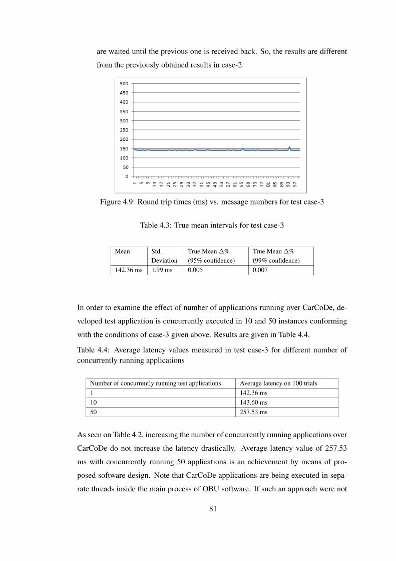
are waited until the previous one is received back. So, the results are different
from the previously obtained results in case-2.
Figure 4.9: Round trip times (ms) vs. message numbers for test case-3
Table 4.3: True mean intervals for test case-3
Mean Std.Deviation
True Mean ∆%(95% confidence)
True Mean ∆%(99% confidence)
142.36 ms 1.99 ms 0.005 0.007
In order to examine the effect of number of applications running over CarCoDe, de-
veloped test application is concurrently executed in 10 and 50 instances conforming
with the conditions of case-3 given above. Results are given in Table 4.4.
Table 4.4: Average latency values measured in test case-3 for different number ofconcurrently running applications
Number of concurrently running test applications Average latency on 100 trials1 142.36 ms10 143.60 ms50 257.53 ms
As seen on Table 4.2, increasing the number of concurrently running applications over
CarCoDe do not increase the latency drastically. Average latency value of 257.53
ms with concurrently running 50 applications is an achievement by means of pro-
posed software design. Note that CarCoDe applications are being executed in sepa-
rate threads inside the main process of OBU software. If such an approach were not
81

be followed, i.e., standalone applications were to be developed for each one of them,
context switching between the processes would clearly decrease the performance.
Consequently, above results support the motivation that we had before such that Car-
CoDe aims to give service to ITS applications with flexible timing requirements in
order of seconds.
82
CHAPTER 5
CONCLUSION
The focus of this thesis is a system architecture, CarCoDe for ITS applications that
are to be developed on different hardware platforms such as OBUs, RSUs or user
devices such as mobile phones. CarCoDe is an abstraction that defines the software
stack for application development as a middle layer between the ITS applications and
the available hardware resources. The software stack has two main layers. The down
layer manages the hardware resources according to the definitions in a configuration
management module. The hardware resources are accessed via the operating system
abstractions. The up layer manages the applications. The communication between
two CarCoDe units is carried out via a third node similar to a server without any direct
connection. This saves CarCoDe implementations from all physical layer issues that
can be encountered during operation such as coverage and interference problems. The
communication rules and message formats are defined together with the identification
of the nodes that participate in the communication. Consequently, CarCoDe enables
the development of independent and concurrent applications that can be developed by
different companies which access the same hardware resources such as CAN network
or GPS sensors.
CarCoDe is not specific to the operating system, communication protocol or hardware
platform. The theses demonstrates the generality of CarCoDe by an instantiation of
it on an OBU with Android Operating System and Websocket communication and
implement an icy road warning application running on top.
The icy road early warning system application utilizes the CAN signals that are mon-
itored by the OBU that indicate that the ESP (Electronic Stability Program) unit of
83

the vehicle. If the ESP signals are more frequent than a determined threshold then
the vehicle sends a message to a central server via 3G interface that includes the icy
road warning message and the GPS coordinates of the vehicle. The server than cor-
relates such icy road warning messages that come from different vehicles within a
certain radius and if it decides icy road condition, it broadcasts a mesage to the vehi-
cles in the area for warning of the icy road. The application demonstrates accessing
different hardware resources such as CAN and GPS and communication via 3G using
Websockets.
The evaluation of the icy road early warning system application development over
CarCoDe shows the amount of wrapper code inside the CarCoDe framework that
would be included in the applications otherwise. In other words, reuse of the under-
lying resources and sharing the common code for initalizing and maintaining these
resources are provided via the proposed software stack, which makes new applica-
tions to be developed and deployed easily.
The future work contains a long list of works in order to realize proposed CarCoDe
architecture in real life with the implemented OBU design. First of all, short range
direct communications should be integrated over DSRC and/or wireless ad-hoc net-
works, which makes CarCoDe also give support to ITS applications with strict timing
requirements. Next, PubSub (Publish and Subscribe) should be implemented for com-
munication interface in order to provide a loosely-coupled messaging scheme based
on keywords, location, etc. via grouping of the clients. Prioritization of the messages
and applications are supported in current implementation of OBU; however, all appli-
cations are executed and messages are transmitted in equal priorities in current state
of the art. With a good system engineering work, ITS applications and corresponding
message types belonging to them may be classified and different priority levels may
be assigned for each one them. Additionally, CarCoDe may be extended with support
of a transparent encryption/decryption mechanism for out-vehicle communications.
Authentication scheme may be also improved in order to enhance security. Although
transmission of binary messages is possible with the current implementation of OBU,
proper design to stream big amounts of binary data over WebSockets is not provided
in current implementation. Furthermore, accessing to in-vehicle CAN bus, OBU soft-
ware should be extended to support also CAN 2.0b data frames with extended length
84
of identifiers and CAN request frames for diagnostic applications. Supports for other
types of in-vehicle networking buses such as FlexRay may be also considered for
extensions. In order to improve comfort inside the vehicles, integration of Bluetooth
and USB interfaces is another issue to be completed via making connections to the
audio/video subsystem of vehicles. Besides, the complete definition and design of
CarCoDe middleware should be completed. Likewise, CarCoDe framework with a
complete software stack should be provided for other types of clients as well.
85

86
REFERENCES
[1] G. Karagiannis, O. Altintas, E. Ekici, G. Heijenk, B. Jarupan, K. Lin, andT. Weil. Vehicular networking: A survey and tutorial on requirements, architec-tures, challenges, standards and solutions. Communications Surveys Tutorials,IEEE, 13(4):584–616, Fourth 2011.
[2] J. Santa, A. Skarmeta, and B. Ubeda. An embedded service platform for thevehicle domain. In Portable Information Devices, 2007. PORTABLE07. IEEEInternational Conference on, pages 1–5, May 2007.
[3] P. Papadimitratos, A. La Fortelle, K. Evenssen, R. Brignolo, and S. Cosenza.Vehicular communication systems: Enabling technologies, applications, and fu-ture outlook on intelligent transportation. Communications Magazine, IEEE,47(11):84–95, November 2009.
[4] IEEE Transactions on Intelligent Transport Systems. Aims and scope.http://ieeexplore.ieee.org/xpl/aboutJournal.jsp?punumber=6979. Accessed on Jan 2015.
[5] Official Journal of the European Union. irective 2010/40/eu of the eu-ropean parliament and of the council. http://eur-lex.europa.eu/LexUriServ/LexUriServ.do?uri=OJ:L:2010:207:0001:0013:EN:PDF. Accessed on Jan 2015.
[6] CAN in Automation. Can history and milestones. http://www.can-cia.de/index.php?id=161. Accessed on December 2014.
[7] Md. Whaiduzzaman, M. Sookhak, A. Gani, and R. Buyya. A survey on ve-hicular cloud computing. Journal of Network and Computer Applications,40(1):325–344, 2014.
[8] A. Hiller, R. Baldessari, B. Bödekker, A. Brakemeier, M. Deegener, A. Festag,and W. Franz. C2C-CC Manifesto: Overview of the C2C-CC System. CAR 2CAR Communication Consortium, v1.1 edition, 8th August 2007.
[9] R. Brignolo, G. Vivo, F. Visintainer, F. Belarbi, and M. Dozza. IST-4-026963-IP: Use cases, functional specifications and safety margin applications for theSAFESPOT Project. SAFESPOT Cooperative Systems for Road Safety, v1.9edition, 15th April 2008.
87

[10] European Telecommunications Standards Institute. ETSI TR 102 638: Intelli-gent Transport Systems (ITS); Vehicular Communications; Basic Set of Appli-cations; Definitions, v1.1.1 edition, Sixth 2009.
[11] M. Bechler, T.M. Bohnert, S. Cosenza, M. Deegener, A. Festag, F. Hausler,and T. Kosch. Pre-Drive C2X Deliverable D1.1: Definition of Pre-DriveC2X/COMeSafety architecture framework. Pre-Drive C2X Consortium, v1.0edition, 1st October 2008.
[12] A. Kovacs, Z. Jeftic, N. Nygren, and T. Hilgers. D.CVIS.2.2: Use Casesand System Requirements. Information Society Technologies, IST-2004-2.4.12eSafety – Cooperative systems for road transport, v1.0 edition, 30th November2006.
[13] G. Goggin. Driving the internet: Mobile internets, cars, and the social. FutureInternet, pages 306–321, 2012.
[14] The FRAME Architecture Website. European its framework architecture.http://www.frame-online.net. Accessed on Oct 2014.
[15] The CVIS Project Website. Cooperative vehicle infrastructure systems. http://www.cvisproject.org. Accessed on Oct 2014.
[16] The HIDENETS Project Website. Highly dependable ip-based networks andservices fp6 project. www.hidenets.aau.dk. Accessed on Oct 2014.
[17] The SAFESPOT Project Website. Cooperative vehicles and road infrastructurefor road safety. http://www.safespot-eu.org. Accessed on Oct 2014.
[18] GeoNet Project. Geo-addressing and geo-routing for vehicular communica-tions. http://www.transport-research.info/web/projects/project_details.cfm?id=44454. Accessed on Oct 2014.
[19] University of Twente. Connect and drive project final demo.http://www.utwente.nl/ctw/aida/news/Connect%26Drive%20final%20Demo/. Accessed on Oct 2014.
[20] H. Stratil and J. Pfister. The easy-obu project. pages EU–00428, 2012.
[21] C.J. Yan, J.X. Guo, and X.Y. Li. The design and realization of obu in free-flowetc system. Applied Mechanics and Materials, 556-562:2081–2084, 2014.
[22] S. Fukang, F. Qiansheng, and M. Hao. Research of obu in etc based on arm.2008.
[23] I.-X. Chen, Y.-C. Wu, I.-C. Liao, and Y.-Y. Hsu. A high-scalable core telematicsplatform design for intelligent transport systems. pages 412–417, 2012.
88
[24] V. Di Lecce and A. Amato. Route planning and user interface for an advancedintelligent transport system. Intelligent Transport Systems, IET, 5(3):149–158,September 2011.
[25] C. Maia, L.M. Nogueira, and L.M. Pinho. Evaluating Android OS for EmbeddedReal-Time Systems. IPP-HURRAY! Research Group, 29th Jun 2010.
[26] U. Hernandez, A. Perallos, N. Sainz, and I. Angulo. Vehicle on board platform:Communications test and prototyping. In Intelligent Vehicles Symposium (IV),2010 IEEE, pages 967–972, June 2010.
[27] K. Lebert and M. Pillin. Advanced hil systems for obdii functionality testing.2001.
[28] Unex Technology Corp. OBE102 Datasheet, 802.11p ETSI TC ITS Communi-cation Unit (EU).
[29] C. Nimodia and H.R. Deshmukh. Android operating system. Software Engi-neering, 3(1):10–13, 2012.
[30] Android Official Website. Android operating system. http://www.android.com. Accessed on July 2014.
[31] O.O. Okediran, O.T. Arulogun, and R.A. Ganiyu. Mobile operating systemsand application development platforms: A survey. Journal of Advancement inEngineering and Technology, 2, 8th August 2014.
[32] S. Brahler. Analysis of the android architecture. Master’s thesis, KarlsruherInstitute of Technology, Tenth 2010.
[33] G. Macario, M. Torchiano, and M. Violante. An in-vehicle infotainment soft-ware architecture based on google android. pages 257–260, 2009.
[34] The Linux Kernel Organization. Readme file for the controller area networkprotocol family. https://www.kernel.org/doc/Documentation/networking/can.txt. Accessed on July 2014.
[35] Jong-Woon Yoo, Youngwoo Lee, Daesun Kim, and KyoungSoo Park. Anandroid-based automotive middleware architecture for plug-and-play of appli-cations. In Open Systems (ICOS), 2012 IEEE Conference on, pages 1–6, Oct2012.
[36] Ke-Chian Su, Hei-Min Wu, Wei-Ling Chang, and Yao-Hsin Chou. Vehicle-to-vehicle communication system through wi-fi network using android smart-phone. In Connected Vehicles and Expo (ICCVE), 2012 International Confer-ence on, pages 191–196, Dec 2012.
89
[37] J. White, C. Thompson, H. Turner, B. Dougherty, and D.C. Schmidt. Wreck-watch: Automatic traffic accident detection and notification with smartphones.Mobile Networks and Applications, 16(3):285–303, 2011.
[38] Internet Engineering Task Force (IETF). The websocket protocol. RFC6455,April 2011.
[39] Internet Engineering Task Force (IETF). Known issues and best practices forthe use of long polling and streaming in bidirectional http. RFC6202, April2011.
[40] A. Russell, G. Wilkins, D. Davis, and Mark Nesbitt. Bayeux protocol –bayeux 1.0.0. http://svn.cometd.org/trunk/bayeux/bayeux.html. Accessed on August 2014.
[41] Wayne D. Websockets alternatives for the androidbrowser. http://yourbusiness.azcentral.com/websockets-alternatives-android-browser-29533.html.Accessed on August 2014.
[42] About html5 websockets. https://www.websocket.org/aboutwebsocket.html. Accessed on September 2014.
[43] V. Pimentel and B.G. Nickerson. Communicating and displaying real-time datawith websocket. Internet Computing, IEEE, 16(4):45–53, July 2012.
[44] D. Skvorc, M. Horvat, and S. Srbljic. Performance evaluation of websocketprotocol for implementation of full-duplex web streams. In Information andCommunication Technology, Electronics and Microelectronics (MIPRO), 201437th International Convention on, pages 1003–1008, May 2014.
[45] J. Perez and J.K. Nurminen. Electric vehicles communicating with websockets -measurements and estimations. In Innovative Smart Grid Technologies Europe(ISGT EUROPE), 2013 4th IEEE/PES, pages 1–5, Oct 2013.
[46] C.-Y. Hsu, C.-S. Yang, L.-C. Yu, C.-F. Lin, H.-H. Yao, D.-Y. Chen,K. Robert Lai, and P.-C. Chang. Development of a cloud-based service frame-work for energy conservation in a sustainable intelligent transportation system.International Journal of Production Economics, 2014.
[47] J. Timpner and L. Wolf. A back-end system for an autonomous parking andcharging system for electric vehicles. 2012.
[48] Freescale. Sabre for automotive infotainment based on the i.mx 6series. http://www.freescale.com/webapp/sps/site/prod_summary.jsp?code=RDIMX6SABREAUTO#. Accessed on April 2014.
[49] The Linux Kernel Organization. The linux kernel archives. https://www.kernel.org. Accessed on July 2014.
90
[50] Google. Android developers. http://developer.android.com/index.html. Accessed on July 2014.
[51] World Wide Web Consortium. Extensible markup language (xml) 1.0 (fifthedition). http://www.w3.org/TR/REC-xml. Accessed on September2014.
[52] Autobahn Project. Open-source real-time framework for web, mobile and inter-net of things. http://autobahn.ws/android. Accessed on July 2014.
[53] ECMA International. The JSON Data Interchange Format, October 2013.
[54] CAN in Automation. Can history and milestones. http://www.can-cia.de/index.php?id=161. Accessed on December 2014.
[55] Bosch. Can fd. http://www.bosch-semiconductors.de/en/ubk_semiconductors/ip_modules_3/produkttabelle_ip_modules/can_fd_1/can.html. Accessed on December 2014.
[56] Linux Foundation. iproute2. http://www.linuxfoundation.org/collaborate/workgroups/networking/iproute2. Accessed onDecember 2014.
[57] linux-can/can utils. Can userspace utilities and tools. https://gitorious.org/linux-can/can-utils. Accessed on September2014.
[58] Android Developers API Guides. Location Strategies. http://developer.android.com/guide/topics/location/strategies.html.
91