a general method for growing large area mesoporous silica
TRANSCRIPT

S1
Supporting Information for:
A General Method for Growing Large Area Mesoporous Silica Thin Films
on Flat Substrates with Perpendicular Nanochannels
Kun-Che Kao,† Cheng-Han Lin,† Tzu-Ying Chen,† Yi-Hsin Liu,*, ∥and Chung-Yuan Mou*,†
†Department of Chemistry and Center for Condensed Matter Sciences, National Taiwan University, Taipei 10617,
Taiwan. ∥Department of Chemistry, National Taiwan Normal University, Taipei 11677, Taiwan
*Corresponding authors, E-mails: [email protected]; [email protected]
Table of Contents:
Experiment details………………………………………………………………………………………S2-4
Figure S1. SEM and TEM images of MSNs from a decane-modified recipe…….………………………S5
Figure S2. Digital-photo images of MSTF on silicon wafer………….…………………………………S6
Figure S3. SEM cross-sectional images of MSTFs during growth………………………………………S7
Figure S4. TEM cross-sectional image of MSTF with decane……….…………………….……………S8
Figure S5. SEM cross-sectional images of MSTFs without decane………………………….…………S9
Figure S6. GISAXS out-of-plane and in-plane linecut signals of MSTFs………………………………S10
Figure S7. SEM images of MSTFs from different co-assembly agents…………………………………S11
Figure S8. SEM and GISAXS of MSTFs grown polymer-coated and CTS-modified glasses…………S12
Figure S9. Cross-sectional SEM images from different ammonia concentrations………………………S13
Table S1. Calculated coherence lengths of MSTFs in Figure SI-6 with Scherrer equation……………S14
S2
Experiment details:
Chemicals. Cetyltrimethylammonium bromide (or cetyltrimethylammonium bromide, CTAB, 99+%,
Acros Organics), tetraethylammonium hydroxide (TEAOH, 20% in aqueous solution, Acros Organics),
tetraethyl orthosilicate (TEOS, ≥ 99%, Aldrich), fumed silica (Aldrich), decane (99+%, Acros Organics),
ethyl alcohol (or ethanol, ≥ 99.5%, Shimakyu’s Pure Chemical), sodium aluminate (NaAlO2, Riedel-de
Haen), glycerin (or glycerol, 95%, Hayashi Pure Chemical Industrial), formaldehyde solution (36 %,
Hayashi Pure Chemical Industrial), and aqueous ammonium hydroxide solution (28-30%, Acros Organics)
were purchased and used without further purification. De-ionized water was filtered in a Millli-Q integral
water purification system (Merck Millipore). One-side polished p-type/B-doped silicon wafer (4”, 1-20 Ω-
cm, Summit-Tech Resource Corp.) and ITO/FTO glass (20 × 20×0.7 mm, 7Ω/10Ω, Global Tech
International) were pre-cleaned with ethanol several times via sonication and rising processes at room
temperature.
Synthesis of Mesoporous Silica Thin Films (MSTF). Synthetic conditions of mesoporous silica thin
films (MSTF) was adapted from a modified procedure of MSN synthesis that we reported previously.16
In
the modified synthesis, decane and ethanol were used together as co-solvents to direct assemblies of CTAB
surfactant micelles. In a typical synthesis, an oil-in-water emulsion was prepared by mixing CTAB (0.193
g), ethanol (6.0 g) and decane (75 - 600 µL) in NH3 aqueous solution (0.1 – 0.9 M, 80 g) at 50°C. Then, a
polished silicon or ITO wafer was directly immersed into the solution, followed by an introduction of

S3
TEOS/ethanol solution (2.0 mL, 20% by volumes) under stirring at 50°C overnight. The molar ratios of
CTAB:H2O:NH3:decane:ethanol:TEOS were calculated to be 1:8400:90:5.8:250:2.8. As-synthesized
mesoporous silica thin films on substrates were purged with N2 to dry the substrate surface prior to SEM
and GISAXS analyses. MSTF specimens for replica experiments were prepared by ethanol rising and
calcination in the air at 500°C for 6 h to remove organic surfactants. For the syntheses using other silica
sources, TEOS were replaced by fumed silica andβ-zeolite seeds with the same molar ratio. The β-
zeolite seeds (Si/Al = 66) were prepared by mixing NaAlO2 (0.25 g), fumed silica (12 g), TEAOH (39 g),
and NaOH (0.6 g) in H2O (32.4 g) under stirring at 50°C for 6 h. Then, the mixture was hydrothermally
treated at 110°C in an autoclave.
Grazing Incidence Small Angle X-ray Scattering (GISAXS). Synchrotron scattering was conducted
at BL23A station at National Synchrotron Radiation Research Center (NSRRC) in Hsinchu, Taiwan. The
incidence X-ray energy of 12 keV (1.033 Å) and the sample-to-detector distance of 3.10 m result in a q-
range of 0.005540-0.2853 Å-1
that is equivalent to real space distance of 2.2-113 nm. The angle of
incidence of each X-ray beam was varied between 0.1 and 0.3°. The scattering data extraction was
performed in an X-ray scattering image analysis package (POLAR) installed in NSRRC. Alternatively, in-
house scattering was conducted by a grazing-incidence geometry (Nano-Viewer, Rigaku) with a two-
dimensional (2D) area detector (Rigaku, 100K PILATUS). The instrument in the Department of Chemical
and Materials Engineering, National Central University (Taoyuan, Taiwan) is equipped with a 31 kW mm-2

S4
generator (rotating anode X-ray source with a Cu Kα radiation of λ = 0.154 nm). The scattering vector, q (q
= 4π/λsinθ), along with the scattering angles θ in these patterns were calibrated using silver behenate (CAS
number of 2489-05-6). The thin films were mounted on a z-axis goniometer with an incident angle of 0.1-
0.3°.
Scanning Electron Microscope (SEM). Top-view and edge-view micrographs were taken on a field
emission scanning electron microscope (Hitachi S-4800) operated at accelerating voltages of 5 kV and
15kV, respectively. The MSTF specimen was loaded onto a plate holder with conducting carbon tape
adhered at the bottom and silver paint coated at the edges of wafers. The whole specimen was baked at
80°C overnight prior to SEM imaging.
Focus Ion beam (FIB) for cross sectional micrograph Cross-sectional specimens were prepared by
focus ion beam and electron beam systems (FIB/SEM, JEOL JIB-4500 and FEI Nova 200 Dual Beam).
The thin film samples were deposited with a thick layer of amorphous carbon for specimen protection. The
ion source (gallium) accelerated at a voltage of 5-30 kV was employed to cut thin film into slice samples
with dimensions of 100 × 100 × 50 nm3 inside the FIB chamber. The slice was laid down on a copper grid
with the film lateral orientation parallel to the cross sectional view under TEM imaging.
Transmission Electron Microscope (TEM). The cross sectional micrograph was taken on a
transmission electron microscope (Hitachi H-7100) with an accelerating voltages of 200 kV.
S5
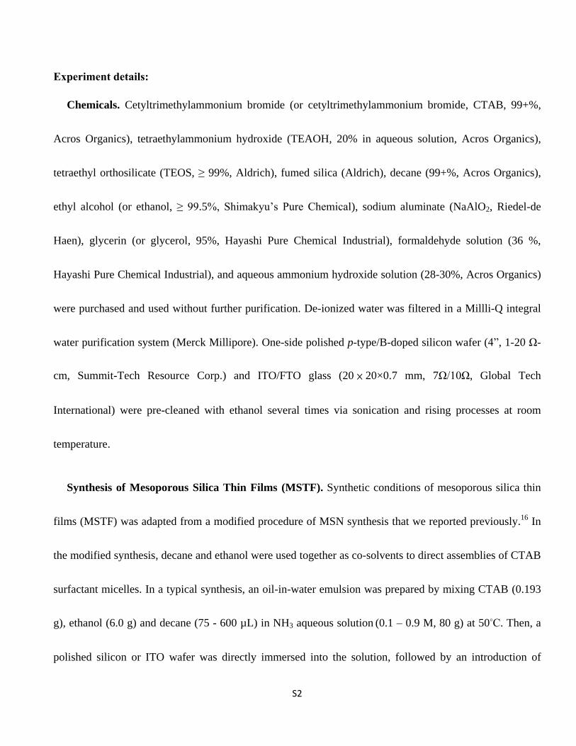
Figure S1. (a) Representative SEM and (b) TEM images of free-standing mesoporous silica nanoparticles
(MSNs) synthesized from a conventional recipe with decane. The averaged basal dimensions of the flat
nanoparticles are 94±22 nm from the TEM statistic results.

S6
Figure S2. Digital-photo images of mesoporous silica thin film growing on a centimeter-wide Si wafer.

S7
Figure S3. Cross-sectional SEM images of MSTF with decane at reaction time of (a) 5 min, (b) 15 min, (c)
30 min, (d) 120 min, (e) 360 min and (f) the statistic results of these thicknesses variations up to 23 h.

S8
Figure S4. (a) A cross sectional TEM image of MSTF with decane and (b) TEM contrast analysis of ten
consecutive slabs within the blue box area. The white image resulting in higher counts in intensity (peaks
in b) represents pore space (5.7± 0.5). The gray image resulting in lower counts in intensity (valleys in b)
represents silica wall (2.1± 0.4). Boundaries between pores and walls are defined from the peak widths at
their half maximum heights.

S9
Figure S5. Cross-sectional SEM image of MSTF without decane at reaction time of (a) 15 min, (b) 30 min,
(c) 120 min, (d) 360 min and (e) the statistic results of these thicknesses from above samples.
(b)

S10
Figure S6. Corresponding out-of-plane (qz) and in-plane (qy) converted linecut signals from GISAXS
image patterns shown in Figure 2. (a) nd-MSTF and (b) MSTF synthesized with introduction of decane.

S11
Figure S7. SEM images of typical MSTFs from different co-assembly agents grown on Si wafers where
pore diameters were individually analyzed and labelled in the parenthesis. (a) Ethyl acetate (3.0 ± 0.5 nm),
(b) hexadecane (3.5 ± 0.4 nm), (c) Petroleum ether (4.9 ± 1.2 nm), (d) Pentyl ether (6.6 ± 1.5 nm).
S12
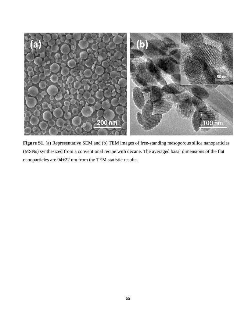
Figure S8. Top-view SEM images of typical MSTFs grown on chemically treated Si wafers where
applicable contact angles were individually measured and labeled in the parenthesis. (a) ethanol (62.2°), (b)
HF (82.6°), and (c) trimethylchlorosilane (98.4°) and MSTFs individually grown on (d) ITO, (e) FTO, (f)
sapphire surfaces.
S13
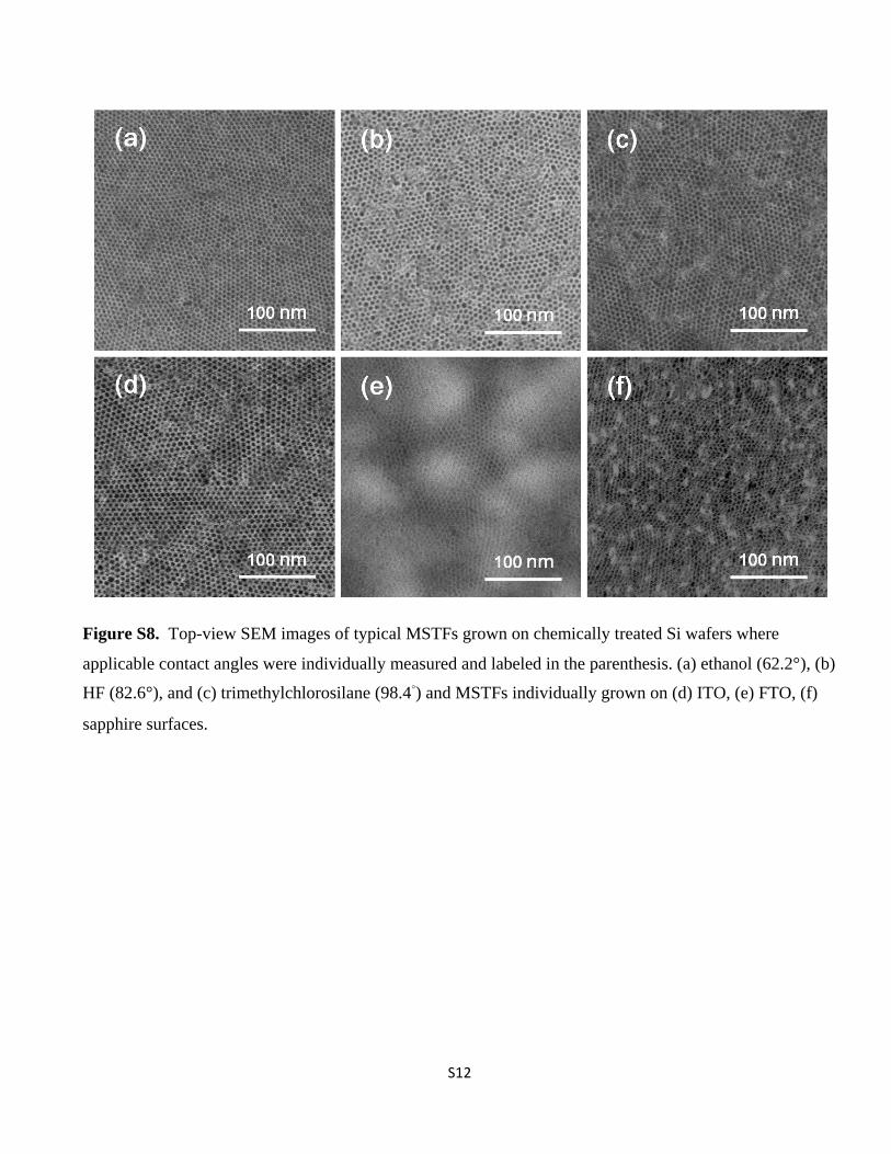
Figure S9. Cross-sectional SEM images of MSTFs synthesized with (a) 0.3 M, (b) 0.6 M, and (c) 0.9 M of
ammonia solution. (d) A plot of MSTFs thickness as a function of ammonia concentration.

S14
Table S1. Calculated coherence lengths of MSTFs in Figure S6 with Scherrer equation
Sample In-plane (nm) Out-of-plane (nm)
nd-MSTF 53.2 49.6
decane-MSTF 140.1 -