a - general introduction 1 - ensreg
TRANSCRIPT


A - GENERAL INTRODUCTION ....................................................... 1
1 THE ORGANISATION OF NUCLEAR SAFETY AND RADIATION PROTECTION
REGULATION IN FRANCE........................................................................................1
2 FRENCH NUCLEAR SAFETY REGULATIONS.............................................................1
2.1 Acts ................................................................................................................................................................1 2.2 Main decrees and ministerial or inter-ministerial orders in force ........................................................2 2.3 ASN decisions ..............................................................................................................................................2 2.4 ASN basic safety rules and guides.............................................................................................................2
3 THE NUCLEAR SAFETY APPROACH IN FRANCE ......................................................2
3.1 The "defence in depth" concept ...............................................................................................................3 3.2 Safety management......................................................................................................................................4 3.3 Operating experience feedback .................................................................................................................4
4 ASN REGULATION OF CIVIL NUCLEAR FACILITIES.................................................4
5 ASN'S SANCTIONS POWERS ....................................................................................5
6 THE FRENCH APPROACH TO THE COMPLEMENTARY SAFETY ASSESSMENTS
(CSAS).....................................................................................................................5
6.1 Specifications consistent with the European specifications .................................................................6 6.2 Specifications broader than the European specifications .....................................................................6 6.3 Specifications which can also take account of some of the situations resulting
from a malevolent act .................................................................................................................................7 6.4 Categorization of the facilities concerned................................................................................................7 6.5 Assistance of a diversified technical expertise ........................................................................................7 6.6 An open and transparent approach ..........................................................................................................8
7 THE TARGETED INSPECTIONS................................................................................8
7.1 Organisation of the targeted inspections .................................................................................................8 7.2 Transparency and public information ......................................................................................................9
8 A LONG-TERM APPROACH.......................................................................................9
B - OVERVIEW OF THE FRENCH NPP ..........................................10
9 OVERVIEW OF THE FRENCH NUCLEAR POWER PLANT FLEET............................. 10
9.1 Description of the nuclear power plants............................................................................................... 10 9.1.1 Main characteristics .................................................................................................................................... 11 9.1.2 Description of the main safety systems ................................................................................................... 13
9.2 The main differences between nuclear power plant installations ..................................................... 18 9.3 The periodic safety reviews..................................................................................................................... 19 9.4 Use of probabilistic studies in the reactor safety assessment ............................................................ 20

10 EARTHQUAKES...................................................................................................... 21
10.1 Design of the facilities ............................................................................................................................. 21 10.1.1 Seismic level for which the facilities are designed.................................................................................. 22 10.1.2 Characteristics of the Design-Basis Earthquake (DBE)........................................................................ 22 10.1.3 Conformity of facilities with existing safety requirements.................................................................... 34
10.2 Evaluation of safety margins................................................................................................................... 36 10.2.1 Seismic level leading to significant damage of the fuel assemblies ...................................................... 41 10.2.2 Seismic level leading to a loss of containment........................................................................................ 41 10.2.3 Seismic level leading to non-design-basis flooding ................................................................................ 41 10.2.4 Measures envisaged to reinforce the robustness of the facilities to the seismic risk ......................... 42
11 FLOODING ............................................................................................................42
11.1 Design of the facilities ............................................................................................................................. 43 11.1.1 Floods for which the facilities are designed ............................................................................................ 43 11.1.2 Measures to protect facilities from the flooding risk, including in the design process ..................... 47 11.1.3 Conformity of facilities with the current baseline safety requirements ............................................... 49
11.2 Evaluation of safety margins................................................................................................................... 51 11.2.1 Estimation of margins in the event of flooding ..................................................................................... 51 11.2.2 Measures envisaged to reinforce the robustness of the facilities to the flooding risk....................... 57
12 OTHER EXTREME NATURAL PHENOMENA RELATED TO FLOODING...................60
12.1 Equipment design for these extreme climatic phenomena................................................................ 61 12.2 Evaluation of safety margins................................................................................................................... 62
12.2.1 Estimation of margins in extreme meteorological conditions.............................................................. 62 12.2.2 Measures envisaged to reinforce the robustness of the facilities to extreme meteorological
conditions .................................................................................................................................................... 64
13 LOSS OF ELECTRICAL POWER SUPPLIES AND COOLING SYSTEMS .........................64
13.1 Loss of electrical power supplies............................................................................................................ 65 13.1.1 Loss of the off-site electrical power supplies.......................................................................................... 67 13.1.2 Loss of off-site electrical power supplies and conventional backup supplies .................................... 69 13.1.3 Loss of the off-site electrical power supplies and of the conventional backup
supplies and any other on-site backup electrical power source............................................................ 74 13.1.4 Conclusion on the planned measures to protect the facilities against the risk
of electrical power supply loss .................................................................................................................. 76 13.1.5 Measures envisaged to enhance facility robustness with respect to electrical power
supply losses ................................................................................................................................................ 77 13.2 Loss of the cooling systems / heat sink................................................................................................ 78
13.2.1 Loss of the primary heat sink.................................................................................................................... 83 13.2.2 Loss of the primary heat sink and the alternate heat sink..................................................................... 87 13.2.3 Conclusion on the planned measures to protect the installations against the risk
of losing the ultimate cooling system or the heat sink .......................................................................... 88 13.2.4 Measures envisaged to increase the robustness of the facilities with respect to loss
of the ultimate cooling system / heat sink .............................................................................................. 90
13.3 Loss of the main cooling system combined with loss of the off-site electrical power supplies and the on-site backup supplies.................................................................................. 94 13.3.1 Site autonomy before loss of the normal conditions of core and fuel pool cooling ......................... 95 13.3.2 External actions planned to prevent damage to the fuel....................................................................... 95 13.3.3 Measures envisaged to reinforce the robustness of the facilities with respect
to loss of the main cooling system combined with total loss of the off-site and backup electrical power supplies .............................................................................................................. 95
14 SEVERE ACCIDENT MANAGEMENT.......................................................................95
14.1 Licensee's accident management organisation and measures............................................................ 96 14.1.1 Licensee's accident management organisation........................................................................................ 96 14.1.2 Possibility of using existing equipment.................................................................................................... 97 14.1.3 Identification of factors that can hinder accident management and the resulting constraints....... 100 14.1.4 Conclusion on the organisational provisions for accident management........................................... 105
14.2 Measures envisaged to reinforce accident management capabilities .............................................. 105 14.2.1 Before the fuel in the reactor vessel becomes damaged...................................................................... 106 14.2.2 After the fuel in the reactor vessel has been damaged ........................................................................ 107 14.2.3 After reactor vessel melt-through........................................................................................................... 108
14.3 Maintaining containment integrity after damage to the fuel in the reactor core .......................... 108 14.3.1 Elimination of the risk of high-pressure fuel damage or core meltdown ......................................... 109 14.3.2 Management of the hydrogen risk in the reactor containment .......................................................... 109 14.3.3 Prevention of reactor containment overpressure................................................................................. 110 14.3.4 Prevention of re-criticality ....................................................................................................................... 111 14.3.5 Prevention of basemat melt-through ..................................................................................................... 112 14.3.6 Supply of electricity and compressed air for operation of the equipment used to preserve
the containment integrity......................................................................................................................... 114 14.3.7 Instrumentation required to protect the integrity of the containment.............................................. 114 14.3.8 Ability to manage several accidents in the event of simultaneous core melt /
fuel damage in different units on the same site .................................................................................... 115 14.3.9 Conclusions concerning the planned steps to maintain the integrity
of the containment in the event of a severe accident ......................................................................... 116 14.3.10 Steps envisaged for strengthening maintained containment integrity after fuel damage ................ 116
14.4 Measures to limit radioactive releases in the event of a severe accident........................................ 117 14.4.1 Radioactive releases after loss of containment integrity...................................................................... 117 14.4.2 Accident management after uncovering of the top of the fuel in the pool ...................................... 117 14.4.3 Conclusions concerning the steps taken to limit radioactive releases in the event
of a severe accident .................................................................................................................................. 120
15 CONDITIONS CONCERNING THE USE OF OUTSIDE CONTRACTORS (EXCLUDED FROM THE SCOPE OF THE EUROPEAN "STRESS TESTS") ................121
15.1 Scope of activities concerned by subcontracting............................................................................... 121 15.2 Management of subcontracted activities............................................................................................. 123
15.2.1 Contractor selection procedures............................................................................................................. 123 15.2.2 Steps taken to ensure satisfactory working conditions for the contractor companies.................... 124 15.2.3 Monitoring of subcontracted activities .................................................................................................. 125

15.3 Conclusions on the conditions for the use of contractor companies ............................................ 126 15.4 Measures envisaged by ASN to strengthen the requirements concerning the conditions
for the use of contractor companies.................................................................................................... 128
16 CONCLUSION ...................................................................................................... 129
16.1 Steps to increase the robustness of the facilities (already implemented) ....................................... 130 16.2 Identified safety problems..................................................................................................................... 131 16.3 Strengthening of nuclear safety and forthcoming work ................................................................... 131
C - GLOSSARY.....................................................................................135
1
A - GENERAL INTRODUCTION
1 The organisation of nuclear safety and radiation protection regulation in France
The regulation of nuclear safety and radiation protection in France is based on two main Acts:
Act 2006-686 of 13th June 2006 on transparency and security in the nuclear field (TSN Act);
Planning Act 2006-739 of 28th June 2006 concerning the sustainable management of radioactive materials and waste.
ASN, which has been an independent administrative authority since the TSN Act of 2006, is tasked, on behalf of the State, with regulating nuclear safety and radiation protection in order to protect workers, patients, the public and the environment from the hazards involved in nuclear activities. It also contributes to informing the public in these fields. It assists the Government in the event of a radiological emergency.
Since the TSN Act was passed, ASN has enjoyed greater powers enabling it to punish offenses and take all necessary measures in the event of an emergency.
ASN is run by a commission of five commissioners who perform their duties in complete independence, on a full-time basis, and are appointed for a non-renewable mandate of 6 years.
ASN relies especially on the expertise of the Institute for Radiation Protection and Nuclear Safety (IRSN) and on its advisory committees of experts.
With regard to nuclear safety and radiation protection, after receiving the opinion of ASN, the Government issues the general regulatory texts concerning transparency, nuclear safety and radiation protection, as well as major political decisions regarding nuclear facilities (authorisation of a basic nuclear installation, final shutdown).
Parliament has an oversight role, in particular of the policy undertaken by ASN. The French Parliament's office for the evaluation of scientific and technological options (OPECST) regularly produces reports on particular aspects of nuclear safety and radiation protection. Every year, ASN sends Parliament its report on the state of nuclear safety and radiation protection.
The French High Committee for Transparency and Information on Nuclear Security (HCTISN), created by the TSN Act, is an information, consultation and debating body concerning the hazards linked to nuclear activities and their impact. It comprises elected officials, associations, trades union representatives, qualified personalities, licensees and representatives of the public authorities.
2 French nuclear safety regulations
The French regulations applicable to civil basic nuclear installations are in conformity with various conventions, international standards and European legislation: IAEA "Basic safety standards"; Convention on Nuclear Safety for civil nuclear power generating reactors; Joint convention on the safety of spent fuel management and the safety of radioactive waste management; Euratom treaty; Euratom directive of 25th June 2009 establishing a community framework for the nuclear safety of nuclear installations.; Euratom directive of 19th July 2011 establishing a community framework for the responsible and safe management of spent fuel and radioactive waste (which will be transposed in 2013).
French nuclear safety regulations include all the general legal texts setting down nuclear safety rules, whether binding (Act voted by Parliament, decrees and ministerial orders and ASN regulatory decisions) or non-binding (ASN basic safety rules and guides).
2.1 Acts
The TSN Act of 13th June 2006 on transparency and security in the nuclear field extensively overhauled the legal regime applicable to basic nuclear installations. It in particular made this regime "integrated" with the aim of preventing the hazards and detrimental effects of all types that nuclear facilities are liable to create: nuclear or non-nuclear accidents, radioactive or other pollution, radioactive pollutions and others, production of radioactive wastes or others, noise, and so on. Act 2006-739 of 28th June 2006 on the sustainable management of radioactive materials and waste, known as the "Waste" Act, creates a coherent, exhaustive legislative framework for the management of all radioactive waste.

2
2.2 Main decrees and ministerial or inter-ministerial orders in force
Decree 2007-1557 of 2nd November 2007 on basic nuclear installations and the control, from a nuclear safety point of view, of the transport of radioactive materials, known as the "procedures" decree, implements article 36 of the TSN Act. It defines the framework for carrying out procedures in nuclear facilities and deals with the entire lifecycle of a nuclear facility, from its authorisation decree and commissioning up to final shutdown and decommissioning. Finally, it makes clear the relations between the Ministers responsible for nuclear safety and ASN, in the field of basic nuclear installation safety.
The order of 10th August 1984 on the quality of the design, construction and operation of basic nuclear installations, known as the "quality" order, specifies the steps that the licensee of a nuclear facility must take to define, obtain and maintain the quality of its facility and the conditions necessary for ensuring its safe operation.
The order of 31st December 1999 amended by the order of 31st January 2006 stipulates the general technical regulations, except for water intakes and effluent discharges, designed to prevent and mitigate off-site detrimental effects and hazards resulting from the operation of nuclear facilities.
The order of 26th November 1999 sets the general technical requirements concerning the limits and procedures for water intakes and effluent discharges subject to authorisation in nuclear facilities.
Pressure vessels specifically designed for nuclear facilities are subject to particular requirements that are regulated and monitored by ASN. They are defined in the decree of 13th December 1999 and in specific orders.
ASN has undertaken to incorporate most of these texts into a single order setting out the essential requirements applicable to all basic nuclear installations for the protection of humans and the environment from the risks of accident, chronic pollution or other detrimental effects. This order, known as the "BNI regime order", underwent a number of consultation processes, including two public consultations. It will be submitted to the Ministers responsible for nuclear safety in early 2012, for their signature.
2.3 ASN decisions
Pursuant to article 4 of the TSN Act, ASN can take regulatory decisions to point out decrees and orders issued concerning nuclear safety or radiation protection, which are submitted to the Government for approval.
ASN also issues individual decisions concerning nuclear activities (for example, commissioning authorisation for a basic nuclear installation, authorisation to use radioactive material transport packaging, authorisation to use radioactive sources, definition of requirements concerning the design, construction, operation or decommissioning of a facility, etc.). Since its creation in 2006, ASN has issued about 90 binding decisions, half of which concern water intakes and environmental discharges.
2.4 ASN basic safety rules and guides
On a variety of technical subjects concerning nuclear facilities, ASN has in the past drawn up basic safety rules (RFS). These are recommendations which clarify the safety objectives and describe practices that ASN considers to be satisfactory. As part of the current overhaul of the general technical regulations, the RFS are being gradually replaced by "ASN guides".
There are at present about forty RFS and other technical rules from ASN, which can be consulted on its website.
3 The nuclear safety approach in France
The nuclear safety approach in France is based on:
the prime responsibility of the licensee for the safety of its facilities, under the oversight of ASN ;
continuous improvement of nuclear safety and radiation protection.
The safety principles and approaches presented below were implemented gradually. They included experience feedback from accidents. Safety can never be totally obtained and, despite the precautions taken in the design, construction and operation of nuclear facilities, an accident always remains possible. There must thus be a constant desire to move forwards and to implement a continuous improvement approach in order to reduce the risks.

3
To ensure the safety of nuclear facilities, the French regulations require that they be designed, built and operated to deal with a certain level of risk. These risks in particular comprise natural hazards, such as earthquake and flooding. The regulations also require the implementation of a "defence in depth" arrangement, which consists of a set of redundant, diversified measures (automation, systems or procedures) able to prevent accidents, manage them if they are not preventable or, failing which, mitigate the consequences. These arrangements are regularly checks and systematically reviewed on the occasion of the ten-yearly periodic safety reviews created by article 29 of the Act of 13th June 2006.
3.1 The "defence in depth" concept
The main means of preventing and mitigating the consequences of accidents is "defence in depth". This involves a series of consecutive, independent levels of protection. If one level of protection, or barrier, were to fail, the next level would take over.
An important aspect in the independence of the levels of defence is the use of technologies of different natures ("diversified" systems).
The design of a nuclear facility is based on a defence in depth approach. For example, for nuclear reactors, there are the following five levels:
First level: prevention of abnormal operation and system failures
This entails choosing a robust and prudent design for the facility, incorporating safety margins, able to withstand its own failures or off-site hazards. This implies conducting a study of the normal operating conditions that is as complete as possible, to determine the most severe constraints to which the systems will be subjected. An initial design of the facility incorporating safety margins can then be established. Second level: Control of abnormal operation and detection of failures
This entails designing control and limitation systems which maintain the facility well within its safety limits. For example, if the temperature of a system rises, a cooling system is activated before the temperature exceeds the authorised limit. Monitoring the good condition of the equipment and the correct operation of the systems is part of this level of defence. Third level: managing accidents without core melt
This entails the assumption that certain accidents, which are the most penalising and encompass all the accidents of a given family, can occur, and to design some safeguard systems to deal with them.
These accidents are generally based on conservative hypotheses, in other words it is assumed that the various parameters determining this accident are the most unfavourable possible. Furthermore, the single failure criterion is applied, in other words, in the accident situation, the failure of a component is also postulated. This means that the systems responding in the event of an accident (emergency shutdown, safety injection, etc.) must comprise at least two redundant channels.
Fourth level: managing accidents with core melt
These accidents were examined following that which occurred at Three Mile Island (1979) and are now incorporated into the design of new reactors such as the EPR. The aim is either to rule out these accidents, or to design systems able to deal with them. The study of these accidents will be reassessed in the light of the experience feedback from the Fukushima accident. Fifth level: mitigation of the radiological consequences of significant releases
This involves implementing emergency plan provisions, including population protection measures: sheltering, administration of stable iodine tablets to saturate the thyroid and prevent it from absorbing the radioactive iodine carried by the radioactive plume, evacuation, restrictions on the consumption of water or foodstuffs, etc.

4
3.2 Safety management
Safety management consists in creating a safety culture within the risk management organisations. The safety culture is defined by INSAG1, an international consultative group for nuclear safety reporting to the Director General of the IAEA2, as being a range of characteristics and attitudes which, for both organisations and individuals, ensure that matters relating to the safety of nuclear facilities are given the priority attention warranted by their importance.
The safety culture thus reflects how the organisation and the individuals perform their roles and assume their responsibilities with regard to safety. It is one of the key factors in maintaining and improving safety. It requires that each organisation and each individual pay particular and appropriate attention to safety. It must be expressed at an individual level by a rigorous and prudent approach and a questioning attitude which ensure compliance with rules while leaving room for initiative. It is applied operationally in the decisions and actions relating to the various activities.
3.3 Operating experience feedback
Operating experience feedback contributes to defence in depth. It consists in implementing a reliable system for detecting any anomalies that may arise, such as equipment failures or errors in the application of a procedure. This system should be able to ensure early detection of any abnormal operation and draw the conclusions (particularly in organisational terms) such as to prevent these anomalies from happening again. Operating experience feedback includes events taking place in France and abroad with pertinence for improved nuclear safety or radiation protection. 4 ASN regulation of civil nuclear facilities
The French civil nuclear fleet is the world's second largest. It comprises a total of 150 nuclear facilities: 58 pressurised water reactors producing most of the electricity consumed in France, one EPR type reactor under construction, the various fuel cycle facilities, research facilities and facilities currently undergoing decommissioning.
ASN, with the technical support of IRSN and its advisory committees, devotes particular attention to rigorous regulation of safety. In accordance with the law, it ensures continuous improvement of safety in French civil nuclear facilities, through the process of periodic safety reviews and the incorporation of operating experience feedback.
Every year, ASN performs more than 700 inspections in the French civil nuclear facilities. These inspections are by means of spot-checks and by analysis of the proof of regulatory compliance provided by the licensee.
In addition to this continuous monitoring, the licensees are required – under ASN oversight – to periodically review (generally every ten years) the safety of their facilities, in accordance with part III of article 29 of the TSN Act. The ten-yearly periodic safety review is an opportunity for a detailed inspection of the conformity of the facility with its own nuclear safety requirements. Its aim is also to make changes to the facility in order to improve its level of safety and as far as possible comply with the requirements applicable to the most recent facilities. The safety review enables ASN to assess the possibility of continuing with operation of the facility up until the next ten-yearly periodic safety review.
ASN also examines anomalies occurring in the nuclear facilities. It ensures that the licensee has made a pertinent analysis of the event, has taken appropriate steps to correct the situation and prevent a reoccurrence, and has sent out operating experience feedback. ASN and IRSN also conduct an overall examination of experience feedback about events. This feedback can result in requests to improve the condition of the facilities and the organisation adopted by the licensee, but also in changes to the technical regulations.
Operating experience feedback includes those events occurring in France and abroad with pertinence for enhancing nuclear safety or radiation protection.
Finally, ASN is heavily committed to relations with its foreign counterparts, whether bilateral, European union or international level. ASN is developing active bilateral cooperation (more than 20 cooperation agreements with 1 INSAG: International Nuclear Safety Group 2 IAEA: International Atomic Energy Agency

5
its counterparts); it is a member of several nuclear safety and radiation protection Regulatory Bodies. In compliance with the provisions of the TSN Act and at the request of the Government, ASN also takes part in the French representation to the international and European organisations in charge of nuclear safety and radiation protection.
5 ASN's sanctions powers
In certain situations where the licensee's actions are not in conformity with the regulations or the legislation, or when it is important for it to take appropriate action to deal immediately with the most important risks, ASN has a number of means of action at its disposal.
In the event of failure to comply with the regulations, its available tools are primarily:
ASN official request to the licensee through an inspection follow-up letter;
ASN formal notice to the licensee to regularise its administrative situation within a specified time, or meet certain stipulated conditions;
administrative sanctions, pronounced after formal notice, which can go as far as temporary suspension of operation of the nuclear facility.
The administrative sanctions are defined in articles 41 to 44 of the TSN Act:
placing in the hands of a public accountant of a sum corresponding to the amount of the work to be performed;
performance of the work by another party at the expense of the licensee (any sums previously placed with the public accountant can then be used to pay for this work);
suspension of working of the facility or of a particular operation, until the licensee restores conformity.
The law also makes provision for interim measures taken to safeguard public security, safety and health or to protect the environment. ASN may therefore:
temporarily suspend the operation of a BNI, immediately informing the Ministries responsible for nuclear safety, in case of any serious and imminent risk;
at any time, stipulate the evaluation and the implementation of the measures necessary in the event of a threat to the above-mentioned interests.
In parallel with ASN's administrative actions, reports can be drawn up by the ASN inspectors and forwarded to the public prosecutor's office. 6 The French approach to the complementary safety assessments (CSAs)
As with the Three Mile Island and Chernobyl accidents, detailed analysis of the experience feedback from the Fukushima accident could take about ten years3. The Fukushima accident, triggered by an earthquake and a tsunami on an exceptional scale, confirmed that despite the precautions taken in the design, construction and operation of the nuclear facilities, an accident is always possible. In this context, and given its knowledge of the 150 French nuclear facilities, through its regulation and oversight, ASN considered in the days following the accident that a complementary assessment of the safety of the facilities, with regard to the type of events leading to the Fukushima disaster, should be initiated without delay, even if no immediate emergency measures were necessary. These assessments were carried out in addition to the safety approach performed permanently and described previously.
3 It should be remembered that after the Three Mile Island accident, it took six years to evaluate the proportion of the
reactor core which had melted.

6
These complementary safety assessments are part of a two-fold approach: on the one hand, performance of a nuclear safety audit on the French civil nuclear facilities in the light of the Fukushima event, which was requested from ASN on 23rd March 2011 by the Prime Minister, pursuant to article 8 of the TSN Act and, on the other, the organisation of "stress tests" requested by the European Council at its meeting of 24th and 25th March 2011.
6.1 Specifications consistent with the European specifications
In order to manage the complementary safety assessments, ASN issued twelve decisions on 5th May requiring the various licensees of the nuclear facilities to perform these complementary safety assessments in accordance with precise specifications. The complementary safety assessments concern the robustness of the facilities to extreme situations such as those which led to the Fukushima accident. They complement the permanent safety approach followed. These twelve decisions are appended. To ensure consistency between the European and French approaches, the French specifications for the complementary safety assessments were drafted on the basis of the European specifications produced by WENRA4 and approved by ENSREG5 on 25th May 2011. The provisions of the French specifications are consistent with those of the European specifications. The complementary safety assessment thus consists of a targeted reassessment of the safety margins of the nuclear facilities in the light of the events which took place in Fukushima, that is extreme natural phenomena (earthquake, flooding and a combination of the two) placing considerable strain on the safety functions of the facilities and leading to a severe accident. The assessment first of all concerns the effects of these natural phenomena; it then looks at the loss of one or more systems important for safety involved in Fukushima (electrical power supplies and cooling systems), regardless of the probability or cause of the loss of these functions; finally, it deals with the organisation and the management of the severe accidents that could result from these events.
Three main aspects are included in this assessment:
The steps taken in the design of the facility and its conformity with the design requirements applicable to it;
The robustness of the facility beyond the level for which it was designed; the licensee in particular identifies the situations leading to a sudden deterioration of the accident sequences ("cliff-edge effects"6) and presents the measures taken to avoid them;
All possible modifications liable to improve the facility's level of safety.
6.2 Specifications broader than the European specifications
ASN decided to apply the complementary safety assessments to all French nuclear facilities and not simply to the power reactors. Thus, virtually all of the 150 French nuclear facilities will undergo a complementary safety assessment, including for example the EPR reactor currently under construction, or the spent fuel reprocessing plant at La Hague7. In this respect, the French specifications have been extended compared to those adopted at the European level by ENSREG. As of the beginning of the process, the association of stakeholders, particularly HCTISN, asked ASN to place particular emphasis on social, organisational and human factors, especially subcontracting. The Fukushima accident showed that the ability of the licensee and, as necessary, its subcontractors to organise and work together in the event of a severe accident is a key factor in the management of such a situation. This ability to organise is also a key aspect of accident prevention, facilities maintenance and the quality of their operation. The conditions for the use of subcontracting are also tackled in the French complementary safety assessments.
4 WENRA: Western European Nuclear Regulators’ Association 5 ENSREG: European Nuclear Safety REgulators Group 6 For example, in the case of flooding, the water level would gradually rise and a cliff-edge effect would be reached when the
water level reaches the top of the embankment and floods the entire site. 7 Fewer than about ten facilities are excluded, as their decommissioning is nearing completion.

7
On 3rd May 2011, the HCTISN issued a favourable opinion of the specifications for the complementary safety assessments. The HCTISN opinion is appended.
6.3 Specifications which can also take account of some of the situations resulting from a malevolent act
Even if the Fukushima accident involves no malevolent acts and even if such acts are not considered in the European Council conclusions of March 2011, the complementary safety assessments approach can cover some of the situations arising from such an act.
Malevolent acts are in fact one of the possible causes (equipment failure, natural hazard, human activities) of a loss of electrical power or cooling which could lead to a nuclear accident. The loss of electrical power and cooling, regardless of the cause, are specifically covered by the complementary safety assessments and appear in this report.
Specifically combating malevolent acts is being examined by the European Member States in a group devoted to this subject.
The close link between these subjects (malevolent acts, safety) means that in most of the relevant countries (United States, Canada, Japan, Russia, Finland, Spain, Sweden, Switzerland, Ukraine, etc.) they are dealt with by the nuclear Regulatory Body. In this respect, France is an exception.
6.4 Categorization of the facilities concerned
The complementary safety assessments concern virtually all the 150 basic nuclear installations in France (58 nuclear power generating reactors, EPR reactor under construction, research facilities, fuel cycle plants).
These facilities have been divided into three categories, depending on their vulnerability to the phenomena which caused the Fukushima accident and on the importance and scale of the consequences of any accident affecting them.
For the 79 facilities felt to be a priority, including the 59 power reactors in operation or under construction, the licensees (AREVA, CEA, EDF, Laue-Langevin Institute) submitted their reports to ASN on 15th September 2011. Given the time available, ASN asked the licensees of the priority nuclear facilities to present their conclusions according to the data at their disposal and based on existing safety studies and the expert opinions of the engineers. The licensees were also to propose complementary studies, to be carried out in particular on the weak points and the "cliff-edge" effects identified, as well as an appropriate calendar for these studies.
For the facilities of lower priority, the licensees are required to submit their reports before 15th September 2012.
Finally, the other facilities will be dealt with through appropriate ASN requests, in particular on the occasion of their next ten-yearly periodic safety review, except for about ten facilities for which decommissioning is nearing completion.
The list of nuclear facilities, including those with top priority, is appended to this report.
6.5 Assistance of a diversified technical expertise
In accordance with the principle of the licensee's prime responsibility, which is the keystone of nuclear safety and a principle that is recognised in international legal texts, the complementary safety assessments led first of all, and for each facility concerned, to the production by the licensee of a report in response to the specifications defined by ASN. In order to analyse the reports submitted by the licensees on 15th September 2011, ASN called on the expertise of its technical support organisation, IRSN, which forwarded its report in early November. On 8th, 9th and 10th November 2011, ASN also convened two of the seven advisory committees it consults on the most important subjects: the advisory committee for reactors and the advisory committee for laboratories and plants. These advisory committees, consisting of French and foreign experts, submitted their opinion to ASN on 10th November 2011. This opinion is appended to this report.
At the same time the ANCCLI, the national association of CLIs (local information committees) mandated a number of experts to examine the reports submitted to ASN by the licensees. Several CLIs also initiated analyses: the Fessenheim CLIS sent ASN a study on the risk of flooding for the Fessenheim NPP; the CLIs at
8
Civaux, Dampierre, Golfech, Gravelines, Saint-Laurent and the three CLIs of the Cotentin peninsula forwarded their opinions on the reports from the licensees. Finally, the experts mandated by the Grand Duchy of Luxembourg and the German States of Saarland and Rhineland-Palatinate, as well as the CGT trade union national mines-energy federation, sent ASN analyses of these reports.
The complementary safety assessments thus led to considerable mobilisation on the part of the licensees, experts, stakeholders and ASN.
ASN's initial conclusions on the complementary safety assessments of the priority nuclear facilities are based on a review of all this work and the results of its regulation and monitoring actions. They are the subject of this report.
6.6 An open and transparent approach
ASN attached the greatest importance to this approach being both open and transparent: the French High Committee for Transparency and Information on Nuclear Security (HCTISN), the local information committees (CLI) and several foreign Regulatory Bodies were invited to take part as observers in the targeted inspections carried out by ASN and to attend meetings of the advisory committees. These various stakeholders also received copies of the reports sent in by the licensees. On its website (www.asn.fr) ASN also made available on-line the reports from the licensees, the IRSN report, the opinions of the advisory committees and the follow-up letters to its inspections. Finally, ASN published several information notes and held three press conferences on 9th May, 14th September and 17th November 2011. This ASN report will also be made public and presented to the press. On 8th December 2011, the HCTISN issued an opinion on the complementary safety assessment process. This opinion, which is appended, underlines the fact that the information concerning the Fukushima accident was made known to the public in a satisfactory manner. 7 The targeted inspections
ASN initiated a campaign of targeted inspections on topics related to the Fukushima accident. The purpose of these inspections was to run field checks on the conformity of the licensee's equipment and organisation with the existing baseline safety requirements. The topics dealt with during these inspections were as follows:
protection against off-site hazards, in particular the ability to withstand earthquakes and protection against flooding;
the loss of electrical power;
the loss of heat sinks;
operational management of radiological emergencies.
7.1 Organisation of the targeted inspections
Thirty-eight inspections were scheduled and performed by teams comprising several ASN inspectors accompanied by IRSN representatives. This campaign of inspections involved 110 days of inspection in the field. These targeted inspections were scheduled between June and October 2011. For any given site, they took the form of in-depth inspections lasting several days, involving spot-checks on all the topics mentioned above. They were based on baseline requirements common to the NPPs on the one hand and to civil nuclear facilities on the other. They placed emphasis on field visits rather than documentary checks.
A summary of the targeted inspections is presented in chapter 1 of the report. This summary, based on the inspection follow-up letters, contains the most representative observations for each category of facilities. It is not therefore exhaustive and does not represent ASN's judgement of the safety of these nuclear facilities.

9
All the requests made by the ASN inspectors are available in the follow-up letters sent out to the licensees, posted on the ASN’s website (www.asn.fr).
7.2 Transparency and public information
In the same way as all the other ASN inspection follow-up letters, those concerning the post-Fukushima targeted inspections were posted on the ASN website (www.asn.fr). ASN also wished to involve the representatives of civil society in its inspections. ASN thus proposed that the local information committees (CLIs) of the nuclear facilities and the French High Committee for Transparency and Information on Nuclear Security (HCTISN) could take part in the targeted inspections as observers, subject to the approval of the licensee. ASN also invited the inspectors of the German, Swiss, Belgian and Luxembourg Regulatory Bodies to attend a few targeted inspections in France. More than 100 outside observers thus took part in the targeted inspections carried out by ASN, primarily in the NPPs. 8 A long-term approach
The experience feedback from the Fukushima accident could take about ten years. As a first step it was felt that an immediate evaluation of the robustness of the facilities to extreme situations should be carried out. This is the goal of the complementary safety assessments, which led to an exceptional mobilisation of the licensees, experts, stakeholders and ASN. After the complementary safety assessments on the priority nuclear facilities, ASN considers that the facilities examined offer a sufficient level of safety requiring no immediate shutdown of facilities. At the same time, ASN considers that the continued operation of the facilities demands that their robustness to extreme situations be improved as rapidly as possible. Therefore in the first quarter of 2012, ASN will be imposing a range of requirements on the licensees and will tighten up the safety requirements concerning the prevention of natural hazards (earthquake and flooding), the prevention of risks linked to other industrial activities, subcontractor monitoring and how nonconformities are dealt with. The corresponding ASN decisions will be posted on the www.asn.fr website. ASN will subsequently ensure that the licensees comply with the hundred or so requirements it will have issued and take account of the new safety requirements it will have approved. ASN will also take into consideration the conclusions of the peer reviews conducted at the European level. ASN also considers that additional studies will need to be undertaken to complete certain aspects, in particular the initial analyses carried out by the licensees. It will send the licensees the corresponding requests in letters which will also be posted on its website. In the summer of 2012, ASN will present the progress of all of these measures. ASN will also continue the process of complementary safety assessments of nuclear facilities with lower priority, for which the reports have to be submitted by the licensees before 15th September 2012. ASN considers that these initial complementary safety assessments confirmed the benefits of such an innovative approach, complementing the existing safety approach. It envisages continuing this process of complementary assessment of safety margins by making it a mandatory component of the ten-yearly periodic safety reviews. Finally, ASN will continue to participate actively in all the analyses to be conducted worldwide, in order to gain a clearer understanding of the Fukushima accident.

10
B - OVERVIEW OF THE FRENCH NPP
9 Overview of the French nuclear power plant fleet
9.1 Description of the nuclear power plants
The nineteen French nuclear power stations NPPs) currently in operation are relatively similar. They each station comprises from two to six pressurized water reactors (PWRs), giving a total of fifty eight reactors in service. In addition to this, an EPR-type PWR is currently under construction at the Flamanville site, and an authorisation application has been made for another reactor of this type at the Penly site. For all the reactors in service, the nuclear island was designed and built by Framatome, with Electricité de France (EDF) acting as architect engineer. Today these reactors are all operated by EDF.
The illustration below shows the geographical location of the NPPs in France. There are no French reactors situated in French territories outside main-land France.
Four NPPs are situated by the sea, and represent:
14 reactors in service,
1 reactor under construction,
1 projected reactor, for which EDF has submitted an authorization application.
One NPP with 4 reactors (Blayais) is situated on an estuary, which means it is subject to the influences of both sea and river.
The other sites are situated beside waterways (mainly large rivers).

11
The table below gives a synthesis of the reactors and their geographical situation:
NPP site Number of reactors Geographical situation
Belleville 2 River site
Blayais 4 Estuary site
Bugey 4 River site
Cattenom 4 River site
Chinon 4 River site
Chooz 2 River site
Civaux 2 River site
Cruas 4 River site
Dampierre 4 River site
Fessenheim 2 River site
Flamanville 2 + EPR(under construction) Coastal site
Golfech 2 River site
Gravelines 6 Coastal site
Nogent 2 River site
Paluel 4 Coastal site
Penly 2 + EPR (project) Coastal site
Saint Alban 2 River site
Saint Laurent 2 River site
Tricastin 4 River site
9.1.1 Main characteristics Certain technological innovations have been introduced on the reactors over time as the NPP fleet has grown. The installations can thus be divided into six groups called "series", which differ from one another in certain respects.
The thirty-four 900 MWe reactors consisting of:
the CP0 series, comprising the four reactors at Bugey (reactors 2 to 5) and the two reactors at Fessenheim ;
the CPY reactors, comprising the twenty-eight remaining 900 MWe reactors, which can be subdivided into CP1 (eighteen reactors at Le Blayais, Dampierre-en-Burly, Gravelines and Tricastin) and CP2 (ten reactors at Chinon, Cruas-Meysse and Saint-Laurent-des-Eaux).
The twenty 1300 MWe reactors consisting of:
the P4 reactors, comprising the eight reactors at Flamanville, Paluel and Saint-Alban;
the P’4 reactors, comprising the twelve reactors at Belleville-sur-Loire, Cattenom, Golfech, Nogent-sur-Seine and Penly.
Lastly, the N4 series comprising four 1450 MWe reactors, two at Chooz and two at Civaux.

12
The table below lists the reactors and their characteristics:
Site Number
of reactors
Net power1 (MWe)
Thermal power2 (MWth)
Type of reactor
Date of first divergence
Belleville 2 1310 3817 (4117) P4 Reactor 1 : 1987-9 Reactor 2 : 1988-5
Blayais 4 910 2785 (2905) CPY (CP1) Reactor 1 : 1981-5 Reactor 2 : 1982-6 Reactor 3 : 1983-7 Reactor 4 : 1983-5
Bugey 4 Reactor 2 : 910 Reactor 3 : 910 Reactor 4 : 880 Reactor 5 : 880
2785 (2905) CP0 Reactor 2 : 1978-4 Reactor 3 : 1978-8 Reactor 4 : 1979-2 Reactor 5 : 1979-7
Cattenom 4 1300 3817 (4117) P’4 Reactor 1 : 1986-10 Reactor 2 : 1987-8 Reactor 3 : 1990-2 Reactor 4 : 1991-5
Chinon 4 905 2785 (2905) CPY (CP2) Reactor 1 : 1982-10 Reactor 2 : 1983-7 Reactor 3 : 1986-9 Reactor 4 : 1987-10
Chooz 2 1500 4720 N4 Reactor 1 : 1996-7 Reactor 2 : 1997-3
Civaux 2 1495 4720 N4 Reactor 3 : 1997-11 Reactor 4 : 1999-11
Cruas 4 915 2785 (2905) CPY (CP2) Reactor 1 : 1983-4 Reactor 2 : 1984-8 Reactor 3 : 1984-4 Reactor 4 : 1984-10
Dampierre 4 890 2785 (2905) CPY (CP1) Reactor 1 : 1980-3 Reactor 2 : 1980-12 Reactor 3 : 1981-1 Reactor 4 : 1981-8
Fessenheim 2 880 2785 (2905) CP0 Reactor 1 : 1977-3 Reactor 2 : 1977-6
Flamanville 2 1330 3817 (4117) P4 Reactor 1 : 1985-9 Reactor 2 : 1986-6
Golfech 2 1310 3817 (4117) P’4 Reactor 1 : 1990-4 Reactor 2 : 1993-5
Gravelines 6 910 2785 (2905) CPY (CP1) Reactor 1 : 1980-2 Reactor 2 : 1980-8 Reactor 3 : 1980-11 Reactor 4 : 1981-5 Reactor 5 : 1984-8 Reactor 6 : 1985-7
Nogent 2 1310 3817 (4117) P’4 Reactor 1 : 1987-9 Reactor 2 : 1988-10
Paluel 4 1330 3817 (4117) P4 Reactor 1 : 1984-5 Reactor 2 : 1984-8 Reactor 3 : 1985-8 Reactor 4 : 1986-3
Penly 2 1330 3817 (4117) P’4 Reactor 1 : 1990-4

13
Reactor 2 : 1992-1
Saint Alban 2 1335 3817 (4117) P4 Reactor 1 : 1985-8 Reactor 2 : 1986-6
Saint Laurent 2 915 2785 (2905) CPY (CP2) Reactor 1 : 1981-1 Reactor 2 : 1981-5
Tricastin 4 915 2785 (2905) CPY (CP1) Reactor 1 : 1980-2 Reactor 2 : 1980-7 Reactor 3 : 1980-11 Reactor 4 : 1981-5
(1) Source : Elecnuc, 2011 edition, CEA. (2) the value between parentheses indicates the design value whereas the other value is that stated in the creation authorization decree.
9.1.2 Description of the main safety systems
The heat produced by the fission of uranium or plutonium atoms is used to produce steam. The steam is then expanded in a turbine which drives an alternator that generates a 3-phase electric current of 400,000 Volts. After expansion, the steam passes through a condenser where it is cooled on contact with tubes circulating cold water taken from the sea, from a waterway (river) or from an atmospheric cooling system.
Each reactor comprises a nuclear island, a conventional island, water intake and discharge infrastructures, and possibly a cooling tower.
The nuclear island essentially consists of the nuclear steam supply system comprising the primary system and the systems designed for reactor operation and safety: the chemical and volumetric control (RCV or CVCS), the residual heat removal (RRA or RHRS), safety injection system (RIS or SIS), containment spray system (EAS or CSS), steam generator main feedwater system (ARE or MFMS), electrical, I&C and reactor protection systems. Various support functions are also associated with the nuclear steam supply system: primary waste treatment (TEP or CSTS), boron recovery, feedwater, ventilation and air-conditioning, backup electrical power (diesel generating sets).
The fuel storage pit
The nuclear island also comprises the main steam system (VVP) that removes the steam to the conventional island, and the building (BK) housing the fuel storage pit. Built adjacent to the reactor building, the BK building is used to store the fuel assemblies before and during the plant unit shutdowns and to cool the spent fuel (a third or a quarter of the fuel is replaced every 12 to 18 months depending on the fuel management strategy). The fuel is kept immersed in a pit filled with the water that acts as a radiological shield. The water in the pit contains about 2500 ppm of boric acid to continue to absorb the neutrons emitted by the nuclei of the fissile elements, but which are too few in number to maintain nuclear fission. Furthermore, each fuel element is placed in a metal compartment whose design and separation distance from the other compartments prevent a critical mass being reached. The fuel pit is cooled by the reactor cavity and spent fuel pool cooling and treatment system (PTR or FPC(P)S).
The conventional island equipment includes the turbine, the AC generator and the condenser. Some components of this equipment contribute to reactor safety.
The secondary systems belong partly to the nuclear island and partly to the conventional island.
The safety of pressurised water reactors is guaranteed by a series of strong, independent, leaktight barriers, for which the safety analysis must demonstrate their effectiveness in normal and accident operating situations. There are three barriers:
the fuel cladding (first barrier)
the main primary and secondary systems (second barrier)
the reactor building containment (third barrier).

14
Below is a schematic diagram of a pressurised water reactor:
Core and fuel management
The reactor core consists of rods containing uranium oxide pellets or mixed uranium and plutonium oxides (fuel referred to as MOX) contained in metal tubes, referred to as the “cladding”, grouped in fuel “assemblies”. As a result of fission, the uranium or plutonium nuclei emit neutrons, which in turn produce further fissions: this is known as the chain reaction. These nuclear fissions release a large amount of energy as heat. The primary system water enters the core from the bottom of the reactor vessel at a temperature of about 285°C, flows up along the fuel rods and exits through the top at a temperature of about 320°C.
At the beginning of the operating cycle, the core has a very large reserve of energy. This gradually falls during the cycle, as the fissile nuclei disappear. The rate of the chain reaction, and hence the reactor power, is controlled by:
inserting control rod assemblies containing elements that absorb neutrons, to varying depths in the core. These enable the reactor to be started and stopped and its power level to be adjusted to the electrical power to be produced. Dropping of the control rod assemblies under the effects of gravity triggers automatic reactor trip;
the concentration of boron (absorbing neutrons) in the primary system water is adjusted during operation as the fissile material in the fuel becomes depleted.
At the end of the cycle, the reactor core is unloaded for replacement of part of the fuel. EDF uses two types of fuels in its pressurised water reactors:
uranium oxide based fuels (UO2) with uranium 235 enrichment to a maximum of 4.5%. These fuels are fabricated in several plants in France and abroad, which belong to the fuel suppliers AREVA and WESTINGHOUSE;
fuels consisting of a mixture of depleted uranium oxides and plutonium (MOX). The MOX fuel is produced by the AREVA MELOX plant. The initial plutonium content is limited to 8.65% (average per fuel assembly) and provides an energy equivalence with UO2 fuel initially enriched to 3.7% Uranium 235. This fuel can be used in the 900 MWe reactors for which the decree authorising their creation (the DAC) provides for the use of MOX. There are twenty-two reactors authorized to use MOX.

15
Fuel management is specific to each reactor series. It is characterised in particular by:
the nature of the fuel used and its initial fissile content;
the maximum degree of fuel depletion at removal from the reactor, characterising the quantity of energy extracted per ton of material (expressed in GWd/t);
the duration of an operating cycle;
the number of new fuel assemblies loaded at each reactor refuelling shutdown (generally 1/3 or 1/4 of the total number of assemblies);
the reactor operating mode, to characterise the stresses to which the fuel is subjected The diagram below illustrates a fuel assembly for a pressurised water reactor:

16
The primary system and secondary systems
The primary system and the secondary systems are used to transport the energy given off by the core in the form of heat to the turbine generator set which produces electricity, without the water in contact with the core ever leaving the containment.
The primary system comprises cooling loops (three loops for a 900 MWe reactor, four loops for a 1,300 MWe, 1,450 MWe, or EPR reactor), the role of which is to extract the heat released in the core by circulating pressurised water, known as the primary water. Each loop, connected to the reactor vessel containing the core, comprises a circulating, or primary pump, and a steam generator (SG). The primary water, heated to more than 300 °C, is kept at a pressure of 155 bar by the pressuriser, to prevent it boiling. The entire primary system is located inside the containment. The primary system water transfers the heat to the water in the secondary systems, via the steam generators. The steam generators are heat exchangers containing thousands of tubes through which the primary water circulates. These tubes are immersed in the water of the secondary system and heat it to boiling point without ever coming into contact with the primary water. Each secondary system consists essentially of a closed loop through which water runs in liquid form in one part and as steam in the other part. The steam produced in the steam generators is partly expanded in a high-pressure turbine and then passes through moisture separator-reheaters before final expansion in the low-pressure turbines, from which it is then routed to the condenser. The condensed water is then heated and sent back to the steam generators by the extraction pumps relayed by feed pumps through reheaters. The cooling systems
The purpose of the cooling systems is to condense the steam coming from the secondary system turbine. To do this the condenser is comprised a heat exchanger containing thousands of tubes in which cold water pumped from an outside source (river, sea) circulates. When the steam comes into contact with the tubes it condenses and can be returned in liquid form to the steam generators. The cooling system water heated in the condenser is then discharged to the natural environment (open circuit) or, when the river flow is too low or the heating too great in relation to the sensitivity of the environment, cooled in a cooling tower (closed or semi-closed circuit). The reactor containment building
The PWR reactor containment building fulfils two functions:
protection of the reactor against external hazards;
containment, thereby protecting the public and the environment against radioactive products likely to be dispersed outside the primary system in the event of an accident. The containments are therefore designed to withstand the pressures and temperatures that could be reached in an accident situation, and offer sufficient leaktightness in such conditions.
The schematic diagram below shows the containment building of a 1300 MWe reactor:

17
The containments are of two types:
the 900 MWe reactor containments, consisting of a single wall of pre-stressed concrete (concrete containing steel cables tensioned to ensure compression of the structure). This wall provides mechanical resistance to the most severe design accident pressure and structural integrity against external hazards. Leaktightness is assured by a metal liner on the inside of the concrete wall;
the 1,300 MWe and 1,450 MWe reactor containments, comprising two walls, an inner wall made of pre-stressed concrete and an outer wall made of reinforced concrete. Leaktightness is provided by the inner wall and the ventilation system (EDE or AVS) which, in the annular space between the walls, channels any radioactive fluids and fission products that could come from inside the containment as a result of an accident. Resistance to external hazards is mainly provided by the outer wall.
The photo below shows a view of the exterior concrete of a 900 MWe reactor building:
The main auxiliary and safeguard systems
In normal operation or during normal shutdown of the reactor, the role of the auxiliary systems is to provide basic safety functions: control of neutron reactivity, removal of heat from the primary system and fuel residual heat, containment of radioactive materials. This chiefly involves the chemical and volume control system (RCV or CVCS) and the residual heat removal system (RRA or RHRS).
The purpose of the safeguard systems is to control incidents and accidents and mitigate their consequences. This primarily concerns the safety injection system (RIS or SIS), the reactor building containment spray system (EAS or CSS) and the steam generator auxiliary feedwater system (ASG or EFWS).
The other systems important for safety
The other systems necessary for reactor operation and important for safety include:
the component cooling system (RRI or CCWS), which cools equipment; this system operates in a closed loop between the auxiliary and safeguard systems , and the essential service water system (SEC or ESWS), which uses the heat sink to cool the RRI system;
the reactor cavity and spent fuel pool cooling and treatment system (PTR or FPC(P)S), used notably to remove residual heat from irradiated fuel elements stored in the spent fuel pool;
the ventilation systems, which play a vital role in containing radioactive materials by depressurising the environment and filtering all discharges;

18
the fire-fighting water systems;
the instrumentation & control system and the electrical systems.
9.2 The main differences between nuclear power plant installations
In spite of the standardizing of the French nuclear reactor fleet, a number of technological innovations have been introduced as the design and construction of nuclear reactors have progressed.
Compared with the CP0 series reactors of the Bugey and Fessenhiem NPPs, the CPY series has a different building design, an intermediate cooling system between the system that sprays the containment in the event of an accident and that containing the water from the heat sink, and provides for greater management flexibility.
Significant changes with respect to the CPY series have been made in the design of the circuits and systems protecting the core of the 1300 MWe reactors (plant series P4 and P’4) and the design of the buildings accommodating the installation. The increased power has resulted in a primary system with four steam generators (SG) offering a greater cooling capacity than on the 900 MWe reactors, which have three SGs. Furthermore, the reactor containment has a double concrete wall instead of a single concrete wall with a steel sealing liner as is the case with the 900 MWe reactors.
The P’4 series reactors display a few differences with respect to the P4, notably the fuel building and the design of certain systems.
The N4 series reactors differ from the preceding reactors more particularly in the design of the SGs which are more compact, the design of the primary pumps, and the control room computerisation.
A 1650 MWe EPR-type pressurised water reactor is under construction at the Flamanville NPP, which already has two 1300 MWe reactors. Furthermore, ASN is currently examining an application from EDF to create another EPR PWR on the Penly site.
The EPR reactors under construction at Flamanville (Flamanville 3, BNI 167), and planned at Penly (Penly 3), are four-loop reactors with a unit electrical output of about 1 650 MWe. Compared with the existing power reactors operating in France, they are characterized by the fact that severe accident scenarios are integrated from the design stage. Based on the principle of a quadrupling (4 trains) of the safeguard systems (with a few exceptions) and, in addition to the presence of an aircraft crash-resistant shell (protecting the reactor building, the fuel building and two buildings housing two engineered safeguard trains) to counter external hazards, the EPR incorporates, for example:
prevention measures, in particular: o to prevent high-pressure core meltdown accidents ; o to enhance the reliability of the on-site electric power supplies by adding two diversified diesel
generator sets (ultimate backup); o to protect the water supply of the safeguard systems cooling the reactor core and containment; o by installing the water tank (IRWST tank) directly in the reactor building; o by having an alternate heat sink based on the "reversed" use of the sea discharge channel, to
take in water from the sea;
mitigation measures such as a corium collector under the reactor vessel in the reactor building, or having a double-walled containment with a metallic internal sealing liner in the reactor building.
For the spent fuel pools of the 900 MWe CP0 and CPY series reactors, the fuel assemblies will be placed in storage rack compartments. These storage racks are made from a corrosion-resistant material not specifically designed to absorb neutrons, sub-criticality being guaranteed by the geometric arrangement of the assemblies. The fuel pits of the CP0 series reactors have 313 compartments, while the CPY series have 382.
To load the spent fuel assemblies into the transportation container, the container must be placed in the loading pit, a dedicated location that communicates with the fuel storage pit.
As from the 1300 MWe series reactors, the fuel pit storage racks have been manufactured in a neutron-absorbing material in order to guarantee sub-criticality in spite of a denser storage arrangement than for the preceding reactors.
The fuel pits of the 1300MWe P4 series reactors have 459 storage compartments.

19
As from the P’4 series, the transportation containers are loaded beneath the loading pit. This means that the heavy handling crane used in the CP0, CPY and P4 series reactors is not necessary, allowing the height of the fuel building to be lowered.
The fuel storage pits have capacities of 630 compartments for the P’4 series reactors, 612 for the N4 series reactors, and 1167 for the EPR reactor.
For the EPR reactor, the reactor cavity and spent fuel pool cooling and treatment system (PTR) has an additional train with a diversified heat sink and can be resupplied with electricity by the ultimate backup generator sets.
9.3 The periodic safety reviews
The French safety standard requires French nuclear installations to be designed and built to withstand - without jeopardising their safety - the most severe natural phenomena (earthquakes, floods, etc.) that have already occurred in the surrounding area, with an additional safety margin. Moreover, it requires the implementation of a system of "defence in depth" that consists of a series of redundant and diversified measures (automatic mechanisms, systems or procedures) to prevent the occurrence of an accident or to mitigate its consequences. These measures are checked at each stage in the life of the nuclear installations (examination of the safety options, creation authorisation, commissioning authorisation, etc.) and re-examined systematically during the 10-year safety reviews instituted by article 29 of the act of 13 June 2006. This periodic safety review provides the opportunity for an in-depth examination of the condition of the NPPs, to check that they comply with all the safety requirements. An additional aim of the review is to improve the safety of the installations, particularly by comparing the applicable requirements with those applied by the licensee to more recent NPPs.
The periodic safety reviews therefore constitute one of the cornerstones of safety in France, by obliging the licensee not only to maintain the level of safety of its NPP but also to improve it. The review process
The periodic safety review comprises a number of successive steps.
1. The conformity review: this consists in comparing the condition of the installation to the applicable safety requirements and regulations including, notably, the creation authorisation decree and ASN's requirements. This step ensures that changes to the installation and its operation, as a result of modifications or ageing, comply with applicable regulations and do not compromise the installation's safety requirements. This ten-year conformity check does not relieve the licensee of its permanent obligation to guarantee the conformity of its installations.
2. The safety review: this aims to appraise the safety of the installation and to improve it with respect to:
French regulations and the most recent safety objectives and practices in France and abroad;
operating experience feedback from the installation;
operating experience feedback from other nuclear installations in France and abroad;
lessons learned from other installations or equipment prone to risk.
ASN may rule - possibly after consulting the GPR - on the study topics envisaged by the licensee before the launch of the safety reassessment studies, during the phase known as the periodic safety review orientation phase.
3. Deployment of the improvements resulting from the periodic safety review: the 10-year in-service inspections provide an excellent opportunity to apply the modifications resulting from the periodic safety review. To determine the schedule for the 10-year inspections, EDF has to take into account the deadlines for the performance of hydrostatic tests set by the regulations for nuclear pressure equipment and the frequency of the periodic safety reviews provided for by the TSN Act.
4. Submission of the licensee's report on the conclusions of the safety review: on completion of the 10-year in-service inspection, the licensee sends ASN a report on the conclusions of the safety review. In this report the licensee adopts its position regarding the conformity of its installation with the regulations and on the modifications made to remedy the observed anomalies or to improve the safety of the installation. The review report contains the elements provided for in article 24 of decree 2007-1557 of 2 November 2007, amended.

20
9.4 Use of probabilistic studies in the reactor safety assessment
The demonstration of the safety of these installations is based firstly on a deterministic approach, by which the operator guarantees the resistance of the installation to reference accidents. This approach is supplemented by probabilistic safety assessments (PSA) based on a systematic examination of the accident scenarios to assess the probability of arriving at unacceptable consequences. They provide a global view of safety, integrating the resistance of the equipment and the behaviour of the operators.
The PSAs help to determine whether the measures adopted by the licensee are satisfactory or not. They enable the safety problems relating to the design or operation of the reactors to be prioritized, and constitute a means of dialogue between the licensees and the administration.
For the existing reactors, the PSAs are carried out and updated during the 10-year reviews.
For the future reactors (case of the EPR), the PSAs are developed at the same time as the design becomes clearer so as to highlight situations involving multiple failures for which measures must be taken to reduce their frequency or limit the consequences.
Two types of PSA are used in France:
level-1 PSAs for identifying the sequences of events leading to fuel meltdown and to determine their probabilities;
level-2 PSAs for assessing the probability of releases outside the containment (into the environment), according to their nature and scale.
The level-1 and 2 PSAs are used in the periodic safety reviews to evaluate the frequency of core meltdown or release and, for PSA1, how it has evolved with respect to the evaluation made at the end of the preceding review, by integrating an analysis of the modifications of the system characteristics (equipment reliability for example) and operating practices. The identification of the main factors contributing to the total probability of core meltdown or the probabilities of releases reveals any weak points for which changes to the installation or its operation are considered advisable or indeed necessary. Classifying them in order of importance enables the priority improvements to be determined. If it is decided that modifications are necessary, the PSAs enable the advantages and drawbacks of the envisaged solutions to be measured or evaluated. The appropriateness of these modifications must be demonstrated by analysing their impact on the contributions to the probability of fuel meltdown. These studies take into account both the reactor operating and shutdown states. The table below defines the PSAs currently available and the main categories of initiating events considered per reactor series in France.
Series Events considered for the level 1 and 2 PSA
900 MWe reactors (CP0-CPY)
Failures internal to the reactor (PSA 1 and 2) Fire (PSA 1)
1300 MWe reactors (P4-P’4)
Failures internal to the reactor (PSA 1 and 2)
For the review associated with the 3rd 10-year inspection, the following will also be considered: - events associated with the spent fuel pool building (BK) (EPS 1 and 2); - internal fire and flooding (PSA 1).
1400 MWe reactor
(N4)
Failures internal to the reactor (PSA 1).
A level-2 PSA will be performed for the next safety review.
1650 MWe reactor (EPR) under construction
The level 1 and 2 PSAs will be revised in view of the commissioning authorisation application. They will take into account:
- the events internal to the reactor; - the events associated with the spent fuel pool building (BK); - earthquake; - internal fire and explosion; - internal flooding.

21
Moreover, in the framework of the 3rd general review of the 1300 MWe reactors, a study was conducted to verify the possibility of extending the level-1 PSAs to earthquakes. 10 Earthquakes
An earthquake is an event liable to lead to failures which could affect all the facilities on a site, in particular the systems important for safety. The possibility of an earthquake is factored into the design of the facilities and is periodically reassessed on the occasion of the periodic safety reviews (section 9.3).
The CSAs demonstrated that the current seismic margins on EDF’s NPPs are sufficient to avoid cliff edge effects in case of limited exceeding of the current safety requirements. These CSAs confirmed the interest of the periodic reassessment of the seismic risk on the occasion of each ten-year periodic safety review. This process of seismic risk review at each periodic safety review should be continued. Furthermore, following the analysis of EDF's CSAs reports and the targeted inspections to which this led in the summer of 2011, ASN has identified several areas in which safety could be improved, related to the seismic robustness of the facilities.
With regard to the seismic risk, ASN will therefore require that EDF:
Ensures that the equipment used to control the basic safety functions is protected against fire in the event of an earthquake. The main measures to protect the facilities against fire are not at present all designed to withstand the facility's baseline safety requirements earthquake;
Increases how this risk is taken into account in the day-to-day operation of its reactors: improved operator training, improvement in how the "event-earthquake" issue is considered, compliance with the fundamental safety rule concerning seismic instrumentation (maintenance, operator familiarity with the equipment, calibration). In a number of NPPs, ASN observed deficiencies in the application of the seismic risk safety requirements in force;
For the Tricastin, Fessenheim and Bugey sites, provides a study analysing the seismic robustness of the dykes and other structures designed to protect the facilities against flooding and to present the consequences of a failure of these structures.
Furthermore, following the Complementary Safety Assessments (CSAs) performed on the nuclear facilities in the wake of the Fukushima accident, ASN considers that the safety of the nuclear facilities needs to be made more robust to very unlikely risks that are not currently considered in the design of the facilities or following their periodic safety review, and to include this requirement in the regulatory framework.
These facilities must be given the resources enabling them to deal with, such as:
combination of natural phenomena of an exceptional scale, greater than the phenomena considered in the design or the periodic safety review of the facilities
very long-term loss of electrical power supply or cooling function situations which could affect all the facilities on a particular site.
ASN will thus be requiring that the licensees set up a "hard core" of material and organisational measures to guarantee the operational nature of the structures and equipment, such as to be able to manage the basic safety functions in these exceptional situations. This subject is developed further in part 16 of this report.
10.1 Design of the facilities
In addition to the facility's initial seismic design, and during the course of the reactor second and third ten-yearly outage inspections (VD2 and VD3), ASN specifically requested that the changes to the safety requirements and new scientific knowledge in the field of this hazard and the paraseismic justification to be taken into account. It is important to note that the updating of the “Safe Shutdown Earthquake” SSE on the site is simply one aspect of the periodic safety reviews regarding the seismic field. The development of methods and computing resources used for paraseismic engineering has fine-tuned the evaluation of the seismic strength of buildings and equipment. Reinforcements may therefore be decided, not simply on the basis of a reassessment of the hazard, which constitutes input data for the calculation of structures and equipment, but also on the basis of developments in paraseismic engineering.

22
In addition, seismic operating experience feedback (both nuclear and non-nuclear) and the construction robustness studies are also sources for evaluating seismic conformity.
10.1.1 Seismic level for which the facilities are designed The approach used to define the seismic loads to be considered in the design of the facilities is a deterministic one:
it is postulated that any earthquake known in the region of the site (taking account of historical observations over a period of about 1,000 years) is liable to reoccur with the same characteristics in the position most unfavourable to the facility, while remaining compatible with the geological and seismic data;
from this, the intensity of the "Maximum Historically Probable Earthquake" (MHPE) is deduced;
as part of the safety approach and to take account of uncertainty surrounding the data and the available knowledge, a degree of intensity is arbitrarily added to the MHPE to define the SSE;
the installation is then designed to withstand a hazard level at least equivalent to that of the SSE; reactor safe shutdown, fuel cooling and containment of radioactive products must be guaranteed for this type of earthquake;
this approach also takes account of soil effects and paleo-earthquakes8.
Given the standardisation of the nuclear reactors operated in France, EDF has introduced the notion of the Design-Basis Earthquake (DBE): this is the envelope spectrum of the various SSE spectra associated with the different sites of the same plant series.
Moreover, a basic safety rule (RFS - see 10.1.2) defines acceptable methods for determining all the movements to which the "seismic-classified" civil engineering structures are subjected, based on the seismic motion considered and the corresponding load levels, in order to allow design and verification:
of the civil engineering strength of these structures subjected to the loads resulting from earthquakes and other actions combined with earthquakes;
of the correct behaviour and performance of the equipment in the facility.
Characteristics of the Design-Basis Earthquake (DBE)
ASN requires that basic nuclear installations be designed to withstand an earthquake higher than the maximum earthquake that has occurred during the last thousand years in the area in which they are sited. The licensees are therefore required to define an earthquake for design purposes. The rule for determining this earthquake is defined in a RFS. The RFS defined by ASN are in particular designed to explain the regulatory objectives and, as applicable, describe the practices considered by ASN to be satisfactory. They are periodically reviewed to take account of changing knowledge and new information. The first RFS on the subject, RFS 1.2.c9, dates from 1981. It was revised in 2001, which this revision being known as RFS 2001-0110. These RFS are also used to check the design of the installations in operation on the occasion of the periodic safety reviews, with reinforcements defined as and when necessary. These rules define two seismic levels, the MHPE and the SSE, which is that used to check that the earthquake finally adopted by the licensee in the design of its facility (DBE) is in conformity with the requirement. EDF has adopted a programme of standardised plant series for the nuclear reactors on its nuclear islands, which enabled it to pool the design studies. The other structures, known as the "site structures" were specifically designed for each site.
8 Paleo-earthquake: earthquake which left traces of deformation in the surface geological layers 9 RFS 1.2.c of 1st October 1981 concerning the determination of the seismic motion to be taken into account for the safety
of the facilities 10 RFS 2001-01 of 31st May 2001 concerning the determination of the seismic risk for the safety of surface basic nuclear
installations.

23
The nuclear island comprises:
The reactor building (BR), containing the reactor and all the pressurised reactor coolant systems, and the containment,
A fuel building (BK), housing the new and spent fuel storage and handling facilities,
A safeguard auxiliaries and electrical building (BAS/BL),
A building for the other nuclear auxiliaries (BAN),
An operations building (BW).
The site structures include the other buildings and facilities necessary for the operation of the plant, including the heat sink and the intake channel. In general, the design spectra adopted were determined as follows:
CP0 and CPY: For the design of the CP0 and CPY plant series, the spectral shape used was that known as the "EDF spectrum", defined as the smoothed mean of eight accelerograms recorded during five earthquakes of Californian origin. The accelerations are normalized according to the local seismicity.
P4 and P’4: The DBE for Paluel, the first P4 site, was changed during the course of its construction. At the beginning of construction, the spectral shape used hitherto for the units was that of the "EDF spectrum". During construction, a new spectral shape was taken from that established by the Nuclear Regulatory Commission (NRC - nuclear safety regulator in the U.S.A.) in its Regulatory Guide 1.60, which was also adopted in France as the reference for the design of the 1,300 MWe plant series. For the buildings, this led EDF to use the following in turn:
o the EDF spectrum normalized to 0.2 g. o for a transitional period, the NRC spectrum normalized to 0.2 g. o the NRC spectrum normalized to 0.15 g.
For the following reactors, P4 and P’4, EDF adopted the NRC spectrum normalized to 0.15 g with zero period for the standard DBE applicable to nuclear island design, compatible with the sites chosen for the reactors in this plant series.
N4: The standard DBE spectrum, applicable for the design of structures and facilities for the N4 plant series, is the NRC spectrum normalized to 0.15 g with zero period. It is normalized to a zero period acceleration of 0.15 g in the horizontal directions and 0.133 g in the vertical direction (which differs from the usual rule which has 2/3 of the horizontal spectrum correspond to the vertical spectrum, and corresponds to 2/3 of an acceleration normalized to 0.2 g. This is a design convention for this plant series).
EPR: the DBE is the European EUR spectrum normalized to 0.25 g at zero period. The following table summarises the different design spectra for the nuclear island and site structures:
Site Plant series
Nuclear island DBE Site structure DBE
Bugey CP0 EDF normalized to 0.1 g zero period EDF normalized to 0.1 g zero period
Fessenheim CP0 EDF normalized to 0.2 g zero period EDF normalized to 0.2 g zero period, hors BL
Blayais CPY EDF normalized to 0.2 g zero period EDF normalized to 0.2 g zero period
Chinon CPY EDF normalized to 0.2 g zero period EDF normalized to 0.2 g zero period
Cruas CPY
EDF normalized to 0.2 g zero period, supplemented by a "high-frequency" spectrum normalized to a zero period acceleration of 0. 3 g
EDF normalized to 0.2 g zero period, supplemented by a "high-frequency" spectrum normalized to a zero period acceleration of 0. 3 g

24
Dampierre CPY EDF normalized to 0.2 g zero period EDF normalized to 0.1 g zero period
Gravelines CPY EDF normalized to 0.2 g zero period EDF normalized to 0.2 g zero period
Saint Laurent CPY EDF normalized to 0.2 g zero period EDF normalized to 0.2 g zero period
Tricastin CPY EDF normalized to 0.2 g zero period EDF normalized to 0.2 g zero period, verified at a higher frequency site spectrum, normalized to 0.3 g
Flamanville 1-2 P4 NRC normalized to 0.15 g zero period NRC normalized to 0.15 g zero period
Paluel P4 EDF normalized to 0.2 g, then NRC normalized to 0.2 g, then NRC normalized to 0.15 g
EDF normalized to 0.2 g, then NRC normalized to 0.2 g, then NRC normalized to 0.15 g
Saint Alban P4 NRC normalized to 0.15 g zero periodNRC normalized to 0.1 g, then verified at NRC normalized to 0.132 g
Belleville P’4
For the design of the nuclear island: NRC spectrum normalized to 0.15 g zero period and, for the nuclear island foundations and reinforcements, owing to the low seismicity of the site: NRC normalized to 0.1 g zero period.
NRC normalized to 0.1 g zero period
Cattenom P’4 NRC normalized to 0.15 g zero period NRC normalized to 0.15 g zero period
Golfech P’4 NRC normalized to 0.15 g zero period NRC normalized to 0.15 g zero period
Nogent P’4
For the design of the nuclear island: NRC spectrum normalized to 0.15 g zero period and, for the nuclear island foundations and reinforcements, owing to the low seismicity of the site: NRC normalized to 0.1 g zero period.
NRC normalized to 0.15 g zero period
Penly P’4 NRC normalized to 0.15 g zero period NRC normalized to 0.15 g zero period
Chooz N4
NRC normalized to 0.15 g zero period, (normalized to 0.15 g in the horizontal direction and 0.133 g in the vertical direction) and spectrum offset by reducing the frequencies by a ratio of 2/3 and normalized to 0.12 g zero period.
NRC, offset and normalized to 0.12 g zero period
Civaux N4
NRC normalized to 0.15 g zero period, (normalized to 0.15 g in the horizontal direction and 0.133 g in the vertical direction) and spectrum offset by reducing the frequencies by a ratio of 2/3 and normalized to 0.12 g zero period.
NRC normalized to 0.15 g zero period
Flamanville 3 EPR EUR normalized to 0.25 g zero period EUR normalized to 0.2 g zero period

25
Methodology used to evaluate the Design Basis Earthquake (DBE)
The conformity of the basic nuclear installations with the regulations is periodically checked every ten years, on the occasion of the periodic safety reviews. These reviews are the opportunity to perform an in-depth, detailed conformity examination, to reassess the SSE levels in the light of the most recent data and new knowledge, to re-examine equipment for which seismic resistance is required, to take account of changes in the field of paraseismic engineering and to make the corresponding necessary improvements to the facilities. The seismic motions corresponding to the SSE are established on the basis of a RFS, which has itself evolved to take account of new data and knowledge. The regulatory requirements: RFS 1.2.C and 2001-01:
A deterministic approach is used to define the seismic hazard to be considered in the design of the facilities.
The general approach to characterising the seismic hazard follows 3 steps:
geological and seismic characterisation of the region, to identify zones with homogeneous characteristics,
definition of one or more reference earthquakes,
calculation of the seismic motion at each site.
The approach is, for each site, to look for an earthquake encompassing the known historical earthquakes in the most penalising epicentre positions (in terms of MSK intensity, representative of surface effects) while remaining compatible with geological and seismic data.
The whole of France is covered by seismotectonic zoning.
Information on past earthquakes was obtained from the interpretation of historical archives describing the damage caused, characterising 1,000 years of seismicity (the SisFrance database contains about 10,000 documents describing more than 6,000 events, and 100,000 observation points), plus a catalogue of instrumental measurements taken since the 1960s (CEA/LDG database).
Definition of the MHPE
The “Maximum Historically Probable Earthquakes” (MHPE) are the earthquake or earthquakes which, for the site concerned, produce the highest intensities, bearing in mind that:
the historical earthquakes of the tectonic domain to which the site belongs are considered as being capable of reoccurring under the site,
the historical earthquakes belonging to a neighbouring tectonic domain are considered as being capable of occurring at the point in this domain closest to the site.
The intensity of an earthquake cannot be directly used in the design of a facility.
Earthquakes are described by their response spectrum (given by the zero period acceleration value, expressed in "g"). For this, it is necessary to determine the magnitude and the focal depth of the historical events. For each MHPE, a “Safe Shutdown Earthquake” (SSE) is deduced by means of a simple relationship in terms of MSK11 intensity on the site: Definition of the SSE
The intensity of the SSE on the MSK scale is conventionally defined by:
ISSE= IMHPE +1
The MSK scale was determined such that a one-degree increase corresponds overall to a doubling in the motion parameter.
The SSE response spectrum is obtained by conventionally adopting a magnitude which is that of the MHPE plus 0.5 on the Richter scale. Transition from RFS I.2.c (1981) to RFS 2001-01 (2001)
11 The Medvedev-Sponheuer-Karnik scale (also called MSK scale) is a scale measuring the intensity of an earthquake.

26
The first RFS for determining seismic motion to be considered for the safety of facilities dates from 1981, this is RFS 1.2.c12. It was revised in 2001, becoming known as RFS 2001-0113. The RFS revision retained the general approach and added to the previous text by taking account of changes to scientific knowledge and the seismic operating experience feedback from the previous 20 years.
The main changes to the RFS concern:
the rule for the definition of seismo-tectonic zones in complex fault configurations (fault families).
the use of the available correlations (linking magnitude to intensity and to focal distance) best suited to the French context and established on the basis of a range of homogeneous macroseismic data.
the notion of fixed spectrum: the fixed spectrum characterising nearby earthquakes has been abandoned in favour of a site spectrum set at 0.1 g with infinite frequency. The RFS revision requires a check that the SSE is higher than a minimum level. This minimum level encompasses a moderate earthquake close to the facility (M=4 at 10 km) and a major event (M=6.6 at 40 km). This minimum level is defined for the two site conditions, both rock and sediment. This approach is in conformity with IAEA's recommendation (Seismic Hazard Evaluation for Nuclear Power Plants, Safety Standards series n° NS-G3-3). Considering this minimum level offers a safety margin and compensates for the lack of data available in low-seismicity regions.
The incorporation of seismic operating experience feedback and changing calculation methods: the operating experience feedback from earthquakes in the 1980s showed the significant influence of the surface geological layers, in particular in alluvial zones. These effects, referred to as "site effects" act on the amplitude of the seismic motion, its duration and its frequency. The response spectrum definition was supplemented in the RFS by additional indicators such as strong phase duration, the Arias intensity, the maximum soil speed, etc., which are of use for the designers of structures. Site effects are included by using spectral acceleration attenuation laws, including the complex geometry of sedimentary zones and the geological characteristics of the top thirty metres on the sites (determined by using local instrumental data), which were updated in relation to the previous RFS.
Taking account of new and changing knowledge in the field of geology: in the early 1990s, signs of paleo-earthquakes of a magnitude higher than certain events in the SisFrance base were discovered. These earthquakes left geological traces by disrupting geological layers or modifying the landscape.
Site design response spectrum (design-basis earthquake - DBE):
For the design of each plant series, EDF used a design spectrum encompassing the overall SSE spectrum for each site, using the data and knowledge available at the time. Special steps were taken for sites with seismic characteristics outside the envelope of the standardised plant series (owing to specific local, in particular geological characteristics). Conclusions concerning the adequacy of the Design-Basis Earthquake (DBE)
Following a periodic safety review, the changes decided for a plant series are implemented on each reactor, generally on the occasion of the reactor ten-yearly outage inspection. The modifications are thus deployed to the entire plant series over a time-frame that is consistent with the initial time of construction of the corresponding reactors.
12 RFS 1.2.c of 1st October 1981 concerning the determination of the seismic motion to be taken into account for the safety
of the facilities 13 RFS 2001-01 of 31st May 2001 concerning the determination of the seismic risk for the safety of surface basic nuclear
installations.

27
As at 30th June 2011, the seismic conformity baseline applicable to the various reactors was as follows:
Reactor Plant series
Version of modifications
implemented on the reactor (ten-yearly
outage-VD)
Applicable seismic baseline
Conformity of the DBE with the earthquake chosen by EDF in accordance with the RFS for the version of the modifications applicable as
at 30th June 2011
Bugey 2-4 CP0 VD3 RFS 2001-01 The new SSE was reassessed at 0.145 g, which requires the installation of reinforcements to restore the seismic margins. The work has been completed on these two units.
Bugey 3-5 CP0 VD2 RFS I-2-C The earthquake adopted is covered by the DBE. However, the VD3 baseline showed the need for seismic reinforcements. The work is complete on Bugey 5 and will be completed on Bugey 3 in 2013.
Fessenheim 1 CP0 VD3 RFS 2001-01 The earthquake to be taken into account remains covered by the design-basis earthquake.*
Fessenheim 2 CP0 VD2 RFS I-2-C Far-field earthquakes remain covered by the "EDF 0.2 g" DBE. The near-field earthquakes involved a high-frequency overshoot of the design level, considered to have no impact on the safety of the facility. No modifications were implemented during VD2 (the high frequencies do not intercept the natural frequencies of the buildings). For the VD3 preparations, the earthquake to be considered remains covered by the design-basis earthquake (for RFS 2001-01).*
Blayais CPY VD2 RFS I-2-C RFS 2001-01 was used in the preparations for VD3 and shows that the minimum fixed earthquake and the site SSE are both covered by the DBE.
Chinon CPY VD2 RFS I-2-C The earthquake defined in RFS I-2-C encompassed the DBE. In the preparations for the VD3, the earthquakes resulting from RFS 2001-01 entailed an overshoot above 7 Hz. A study was carried out to demonstrate that there was no impact on the site structures, the buildings and the equipment of the nuclear island. A study is in progress concerning the reactor building internal structures.
Cruas ** CPY VD2 RFS I-2-C The earthquake resulting from application of the RFS I-2-C is covered by the DBE. The earthquake resulting from application of the RFS 2001-01 shows an overshoot above 8 Hz. The analyses performed during the preparations for VD3 show that there is no impact on all the buildings and equipment.

28
Dampierre CPY VD2 RFS I-2-C The DBE encompasses the earthquake selected by RFS I-2-C. In the preparations for VD3, the DBE was compared with the earthquakes resulting from RFS 2001-01. For the nuclear island, the overshoots above 10 Hz are considered to have no impact. For the site structures, the overshoots above 2 Hz were the subject of verifications. They have no impact on the site buildings and structures.
These overshoots are linked to the adoption in the new rule of the minimum fixed earthquake, given the low level of local seismicity.
Gravelines CPY VD2 RFS I-2-C The earthquake resulting from RFS I.2.C was justified at the time of VD2. During the preparations for VD3, the earthquake resulting from RFS 2001-01 was verified. The new reference earthquake entailed an overshoot for the nuclear island beyond 5 Hz, considered to have no impact. The implementation of reinforcements and minor changes to the site structures and equipment has been completed at Gravelines 1 and will be carried out during the ten-yearly outages on the other reactors (end of works in 2017).
Saint Laurent CPY VD2 RFS I-2-C The nuclear island DBE encompasses the earthquake resulting from RFS I.2.c and 2001-01. The earthquake for the site structures is covered by the earthquake resulting from RFS I-2-c and entails slight overshoots beyond 7 Hz, for the earthquake resulting from RFS 2001-01. The absence of impact on the site structures and equipment was confirmed.
Tricastin 1-2 CPY VD3 RFS 2001-01 For the design of Tricastin, two reference earthquakes were used: EDF 0.2 g and DSN 0.3 g, both of which encompass the earthquakes resulting from the application of RFS I-2-C and 2001-01.
Tricastin 3-4 CPY VD2 RFS I-2-C For the design of Tricastin, two reference earthquakes were used: an EDF spectrum normalized to 0.2 g and a spectrum with more high frequencies normalized to 0.3 g to take account of the specific characteristics of the site. These earthquakes encompass those resulting from application of RFS I-2-C and 2001-01.
Chooz N4 VD1 RFS 2001-01 The earthquake resulting from RFS 2001-01 is covered by the DBE.
Flamanville 1-2 P4 VD2 RFS 2001-01 The DBE encompasses the earthquakes resulting from RFS I-2-C and 2001-01.
Paluel P4 VD2 RFS 2001-01 The DBE encompasses the earthquake resulting from the application of RFS 2001-01 up to 25 Hz. The slight overshoot above 25 Hz has no impact.
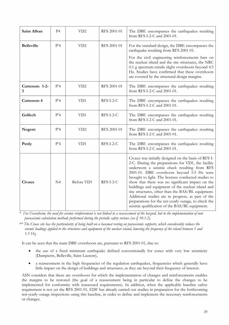
29
Saint Alban P4 VD2 RFS 2001-01 The DBE encompasses the earthquakes resulting from RFS I-2-C and 2001-01.
Belleville P’4 VD2 RFS 2001-01 For the standard design, the DBE encompasses the earthquake resulting from RFS 2001-01.
For the civil engineering reinforcements bars on the nuclear island and the site structures, the NRC 0.1 g spectrum entails slight overshoots beyond 4.5 Hz. Studies have confirmed that these overshoots are covered by the structural design margins.
Cattenom 1-2-3
P’4 VD2 RFS 2001-01 The DBE encompasses the earthquakes resulting from RFS I-2-C and 2001-01.
Cattenom 4 P’4 VD1 RFS I-2-C The DBE encompasses the earthquakes resulting from RFS I-2-C and 2001-01.
Golfech P’4 VD1 RFS I-2-C The DBE encompasses the earthquakes resulting from RFS I-2-C and 2001-01.
Nogent P’4 VD2 RFS 2001-01 The DBE encompasses the earthquakes resulting from RFS I-2-C and 2001-01.
Penly P’4 VD1 RFS I-2-C The DBE encompasses the earthquakes resulting from RFS I-2-C and 2001-01.
Civaux N4 Before VD1 RFS I-2-C
Civaux was initially designed on the basis of RFS I-2-C. During the preparations for VD1, the facility underwent a seismic check resulting from RFS 2001-01. DBE overshoots beyond 5.5 Hz were brought to light. The licensee conducted studies to show that there was no significant impact on the buildings and equipment of the nuclear island and site structures, other than the BAS/BL equipment. Additional studies are in progress, as part of the preparations for the ten-yearly outage, to check the seismic qualification of the BAS/BL equipment.
* For Fessenheim, the need for seismic reinforcement is not linked to a reassessment of the hazard, but to the implementation of new paraseismic calculation methods performed during the periodic safety reviews (see § 10.1.2).
** The Cruas site has the particularity of being built on a basemat resting on paraseismic supports, which considerably reduces the seismic loadings applied to the structures and equipment of the nuclear island, lowering the frequency of the island between 1 and 1.5 Hz.
It can be seen that the main DBE overshoots are, pursuant to RFS 2001-01, due to:
the use of a fixed minimum earthquake defined conventionally for zones with very low seismicity (Dampierre, Belleville, Saint Laurent),
a reassessment in the high frequencies of the regulation earthquakes, frequencies which generally have little impact on the design of buildings and structures, as they are beyond their frequency of interest.
ASN considers that these are overshoots for which the implementation of changes and reinforcements enables the margins to be restored (the goal of a reassessment being in particular to define the changes to be implemented for conformity with reassessed requirements). In addition, when the applicable baseline safety requirement is not yet the RFS 2001-01, EDF has already carried out studies in preparation for the forthcoming ten-yearly outage inspections using this baseline, in order to define and implement the necessary reinforcements or changes.

30
The DBE margins for the nuclear island and the site structures are not identical, in that the site structures were designed on the basis of earthquakes normalized on local seismic characteristics.
The robustness of the civil engineering structures participating in prevention of the loss of the heat sink (in particular the pumping station and networks) or electrical power supplies (in particular the electrical and diesel buildings) shall be analysed by EDF in the study that ASN will ask it to conduct on the incorporation of long-term H1 or H3 site situations (see section 13). It is important to note that updating of the site SSE is simply one part of the periodic safety reviews concerning seismic aspects. The development of computing methods and resources utilized by paraseismic engineering has helped fine-tune the evaluation of the seismic strength of buildings and equipment. Reinforcements can thus be decided, not solely on the basis of a reassessment of the hazard, which constitutes input data for the design of structures and equipment, but also on the basis of changes to paraseismic engineering. Thus, the seismic modifications implemented during the VD3 at Fessenheim, are not due to a reassessment of the seismic hazard, but to the use of new computing methods.
Seismic operating experience feedback (nuclear and non-nuclear) and construction robustness design studies are also sources for the evaluation of seismic conformity. In addition to the initial seismic design of the facility, ASN made specific requests on the occasion of the second and third ten-yearly outage reactor inspections, to take account of changes to the baselines and to available scientific data in the field of the hazard and the paraseismic justification.
ASN considers that the seismic reassessments conducted since the design of the units, based on reassessed hazards and changes to paraseismic justification methods, were performed satisfactorily.
ASN noted the conformity of the reactors with this baseline, subject to the implementation of identified reinforcements and changes, scheduled for the ten-yearly outages.
10.1.2 Steps designed to protect the facilities from the earthquake for which they are designed
Identification of systems, structures and components (SSCs) for which availability is required subsequent to an earthquake
The plant shall be designed so that it can be restored to and kept in safe shutdown conditions after an earthquake corresponding to the SSE.
The licensee shall demonstrate that it meets the three safety objectives:
controlled reactivity (including the safe shutdown function),
residual heat removal,
containment of radioactive materials.
These objectives are the responsibility of equipment, systems and structures to which behaviour requirements are attributed (integrity, functional capability, operability).
integrity: applies to pressure vessels playing a safety role; it aims to maintain the containment capacity.
functional capability: aims to maintain the function of a system for a mission duration defined in the safety analysis report.
operability: aims to ensure correct working of the mobile parts and mechanisms, for performance of the safety functions of this equipment and the nominal working of actuators and control systems.
During the design process, the equipment, systems or structures necessary for the safety demonstration are classified on a list of elements important for safety. Depending on its safety role, this equipment is placed in a safety class which comprises seismic classification requirements defined by the regulations or by the RFS (RFS IV.1.a of 21st December 1984 concerning the classification of certain mechanical equipment, RFS IV.1.b concerning the design and classification of safety-class electrical equipment, etc.).

31
These elements are designed to perform their functions in all plant operating situations (normal, transient, incident and accident). The behaviour requirements are determined by the role to be played by the equipment, systems or structures in the various operating situations.
The seismic classification requires justification either by calculation, or by testing on a vibrating table, or through analysis on a case by case basis.
The resulting design requirements are proportional to their safety class. For the main primary system, they are defined by the order of 26th February 197414 and for the main secondary system by RFS II.3.815, for all the reactors in service. For level 2 and 3 mechanical equipment, the design requirements and criteria are defined by RFS IV.2.a of 21st December 1984 concerning the requirements to be taken into account in the design of safety-classified mechanical equipment, carrying or containing a pressurized fluid and classified level 2 or 3.
For electrical equipment, the requirements are defined in RFS IV.1.b of 31st July 1985 concerning the design and classification of safety-classified electrical equipment.
RFS V.2.g16 defines the acceptable methods for determining all the movements to which the "seismic classified" civil engineering and structures are subjected, on the basis of the seismic motion considered, as well as the corresponding load levels, to allow the design and verification:
of the civil engineering strength of these structures subjected to the loads resulting from earthquakes and other actions combined with the earthquakes,
of the correct behaviour and performance of the equipment in the facility.
Following the adoption of the new RFS 2001-01 concerning the determination of the seismic motion for surface basic nuclear installations, in place of RFS I.2.c dating from 1981, RFS V.2.g was revised to take account of changes to paraseismic engineering know-how (for example, the development of dynamic analyses on detailed 3-dimensional models, the improved knowledge of soil behaviour and soil/structure interactions, the development of time-based calculations on advanced models, the incorporation of non-linear phenomena, whether of geometrical or rheological origin) and to ensure consistency with RFS 2001-01. These requirements are included in ASN guide 2-0117.
For example, the seismic changes implemented on the occasion of the Fessenheim VD 3, are not due to a reassessment of the seismic hazard, but to the use of new computation methods.
In its CSAs reports, EDF recalls that it sets seismic classification requirements for:
IPS (important for safety) equipment (defined in the design) and certain non-IPS equipment, on a case by case basis,
the PAM (post-accident monitoring) measures,
certain equipment required for safety sectorisation,
equipment adjacent to a seismic classified system and needed to ensure the isolation between a seismic-classified part and a non-seismic-classified part,
equipment containing radioactive materials which, in the event of a leak, could lead to significant releases.
Equipment which, if it fell, could lead to the loss of seismic-classified IPS equipment, is the subject of seismic verification (see § indirect effects of an earthquake).
In the CP0 plant series, about 5,600 equipment items are seismic-classified. In the CPY plant series, about 5,200 equipment items are seismic-classified. In the 1,300 MW plant series, about 8,500 equipment items are seismic-classified. In the N4 plant series, about 9,200 equipment items are seismic-classified.
14 Order of 26th February 1974 concerning the reactor coolant system (RCS) for pressurised water reactors (PWR) 15 RFS II.3.8 of 8th June 1990 concerning the construction and operation of the main secondary system, for all 900 and
1,300 MWe plant series 16 RFS V.2.g of 31st December 1985 concerning seismic calculations for civil engineering structures 17 ASN Guide 2-01 of 26th May 2006 on taking account of the seismic risk in the design of civil engineering structures for
basic nuclear installations

32
ASN considers that the implementation of this baseline safety requirement by EDF is satisfactory.
Main operating provisions
Operating principle in the event of an earthquake:
In order to be able to rapidly take adequate steps to bring the plant units to the shutdown state felt to be safest for each one, and maintain it in this state, or to continue with operations, RFS I.3.b recommends the installation of seismic instrumentation for pressurised water reactors.
The procedure to be followed then depends on the level of the earthquake in relation to the Half Design Response Spectrum (½ DRS: spectrum corresponding to an earthquake which should not modify the behaviour of the facility with regard to an SSE occurring subsequently and the spectrum of which is half the DBE).
if the ½ DRS threshold is not exceeded, each unit can continue to operate provided that a visual inspection is carried out on structures and equipment.
if the ½ DRS threshold is exceeded, the units must go to the shutdown state considered for each unit to be the safest. The resumption of operation may only be initiated with the approval of ASN.
The operation of this seismic instrumentation was the subject of a series of targeted inspections by ASN in 2011.
During these targeted inspections, ASN on certain sites identified nonconformity of the seismic instrumentation with RFS I.3.b, problems with operator interpretation of the measurements taken by this instrumentation, and a lack of clarity in the reactor shutdown procedures. These deviations can delay reactor shutdown as specified in RFS I.3.b, or could even lead to this decision not being taken. Moreover, the required inspection following the occurrence of the ½ DRS, defined by RFS I.3.b and constituting a prerequisite for restart of the reactors on the site, is not clearly defined. ASN will require that EDF perform a conformity check on its facilities with respect to RFS 1.3.b.
Furthermore, even though a degree of training has been dispensed, the exercises triggered by ASN during the inspections showed that on most sites, the operators had problems in analysing the data produced by the seismic instrumentation, which could delay shutdown of the reactors or even lead to this decision not being taken. ASN will require that EDF define and monitor an operations personnel training programme to enhance their preparation for a possible earthquake. ASN will also require that EDF study the advantages and drawbacks of implementing automatic shutdown of its reactors in the event of seismic loading, enabling the reactor to be shutdown to a safe state appropriate to each site, if the seismic level corresponding to a spectrum with half the amplitude of the design response spectrum is exceeded.
Protection against the indirect effects of the earthquake
SSC failure, "event earthquake" approach
In addition to the design-basis earthquake resistance of the IPS equipment necessary in the event of an earthquake, the safety approach was supplemented by an approach called the "event earthquake", the aim of which it to prevent damage to an equipment item necessary in the event of an earthquake by an item or structure not seismic-classified. This approach is being implemented on the occasion of the ten-yearly outage inspections. This only considers direct mechanical damage or direct spraying of mechanical or electromechanical equipment. The hypotheses adopted by EDF in the approach are as follows:
equipment that is not designed to withstand an earthquake can fail and thus constitute a potential hazard.
seismic-classified equipment must not have its function or integrity compromised by failure of an item that is not seismic-classified.
no simultaneous occurrence of earthquake and the following is postulated:
o an independent incident or accident condition,
o an independent internal hazard (for example fire),
o another independent external hazard. An examination must be conducted on the possible hazards that non-seismic-classified equipment represents for seismic-classified equipment by:

33
considering the potential hazards representing an effective risk for the target;
checking that none of the equipment items performing safeguard, reactor protection and their support functions is jeopardized.
The list of potential hazards identified in particular includes the structures and items (weighing more than 10 kg) not designed to withstand an earthquake (unfixed loads, handling machinery not tied down, cabinets, fans, civil engineering structures, tanks, large equipment on small piping, equipment running through the premises, false ceilings, piping with a diameter larger than 50 mm, etc.).
The event earthquake approach was extended to the potential damage to the nuclear island buildings by the turbine hall.
When the analysis leads to the need for protection, the measures taken can involve:
relocating the target or the hazard source,
installing reinforcements to ensure the hazard's ability to withstand the earthquake,
installation of protection on the target,
justification of the target's ability to withstand the hazard by analysis or by testing,
modification of the operating conditions of these equipment items.
Implementation of this approach is being requested by ASN on the occasion of the ten-yearly outage inspections (as of the 900 MWe VD2 ). The approach comprises two parts, one national, which can lead to modifications to a plant series, and one local.
During the course of its inspections, ASN observed the difficulty experienced by the licensee with ensuring optimum integration of this requirement on certain sites on a day-to-day basis, in particular during maintenance operations, construction site operations, the use of scaffolding and the utilisation and conservation of handling resources. This is why ASN will be requiring that on each site, EDF ensure the effective implementation of the "event earthquake" approach. Loss of off-site power supplies:
The PWR safety demonstration studies the simultaneous occurrence of a major earthquake and the loss of off-site power supplies, insofar as they are not designed to withstand a major earthquake.
At the same time, EDF introduced the "LOOP combination" which simulates the consequences of an earthquake during an accident transient. The safety case thus gives the combination of incidents and accidents with a LOOP: these transients are only managed by means of seismic-classified equipment.
The total loss of electrical power supplies (situation H3) to a single unit on the site is included in the baseline safety requirements. It is the result of the loss of off-site power supplies associated with the impossibility of restoring the switchboards backed up by the back-up generators in each unit. These backup sources comprise autonomous and functionally independent diesel generators. In the event of the failure of these unit diesel generators to start or connect, it is possible to connect a site emergency generator or a diesel generator belonging to a neighbouring unit.
There is only one emergency generator per site, which is not designed to withstand an earthquake. In the event of a common mode affecting all site backup diesels, only one of the site units could be backed up. In the event of an earthquake, the availability of this emergency generator cannot be guaranteed. ASN sees this as a weak point in the ability of the facilities to deal with an on-site H3 situation, in particular if resulting from an earthquake. ASN duly notes the measures envisaged by EDF to improve the robustness of its facilities vis-à-vis these situations, which in particular consist in ensuring the earthquake robustness of the additional measures defined for the on-site H3 situation. These aspects are also described further in section 13.
ASN considers that the reinforcement objectives proposed by EDF are satisfactory. ASN will thus require that EDF increase the life of its batteries and supplement the electrical backup by emergency diesels, allocated to each reactor, which will have to be a part of the hard-core (see section 16) and will therefore have to withstand significantly higher seismic levels than the DBE.

34
Conditions for access to the site following an earthquake:
In the event of major disruption to roads and structures, the emergency response organisation calls on the public authorities who, in addition to triggering the off-site emergency plan (PPI) if necessary, take special measures. These measures allow on-call personnel to be brought in. The plant safeguard systems requiring external supplies (fuel, oil, etc.) have an autonomy of several days, varying according to the systems and described in the safety analysis report.
ASN observes that EDF has not demonstrated site autonomy for a period of fifteen days (time considered by EDF for restoration of the off-site power supply) in all circumstances, in particular following an earthquake or flooding leading to the site being isolated (these aspects are detailed in part 13 of this report).
ASN will require that EDF secure its on-site stocks of fuel and oil and ensure that they can be replenished in all circumstances, to guarantee an autonomy of at least 15 days. Earthquake-induced fire risk:
The buildings consist of sectors to prevent the propagation of a fire. These sectors comprise a seismic strength requirement. The buildings and premises housing IPS equipment are subject to general equipment installation requirements to prevent the loss of the safety function in the event of a fire (in particular, redundant systems must not be installed in the same sectors, cables must be geographically separated whenever possible, and so on).
Fire-fighting systems are subject to seismic strength requirements and they are separated from non-seismic-classified parts by seismic-classified isolating devices. However:
the sectoring, fire detection and fixed extinguishing systems are designed to withstand to half of the DBE for the 900 MW and 1,300 MW plant series;
operating experience feedback mentions outbreaks of fire in normal operating situations on IPS equipment;
fire detection and fixed extinguishing systems are not electrically backed-up by seismic qualified equipment;
seismic qualification of fire detection only applies to equipment installed within the context of the study of the reference accidents in the safety analysis report.
ASN will require EDF to reinforce the fire sectoring, fire detection and fixed extinguishing systems so that they can withstand a SSE, and electrically back up the detection and control systems of fire protection system with seismic-qualified equipment. Earthquake-induced explosion risk:
Application of the SSE design requirement to the hydrogen systems and inclusion of the "event earthquake" approach for lines carrying hydrogen in the nuclear island, is in progress on the N4 plant series, and is scheduled:
between 2009 and 2019 for the 900 MWe rectors,
between 2015 and 2023 for the reactors of the 1,300 MWe plant series.
ASN will ask EDF to speed up application of the SSE design requirement to hydrogen systems and the implementation of the "event earthquake" approach for lines carrying hydrogen.
The hydrogen presence detectors and the shut-off valves situated outside the reactor building are not covered by seismic strength requirements. ASN will be asking EDF to guarantee the ability of this equipment to withstand a SSE and to supplement the forthcoming safety requirements. ASN considers that management of the explosion risk, for these lines, also entails correct application of a maintenance programme and ensuring that there are no nonconformities.
10.1.3 Conformity of facilities with existing safety requirements

35
The conformity of nuclear facilities with the safety requirements that are applicable to them is a key component of their safety and their robustness to accident initiators or hazards. For ASN, this conformity must be continuously managed and be based on a systematic search for possible nonconformities, which must be dealt with in a way commensurate with the safety stakes. The detection, notification and processing of nonconformities are now the subject of ASN requirements defined in the order of 10th August 198418 and in the general operating rules for nuclear power plants which, for example, specify the time within which the reactors must be shut down according to the importance of the nonconformity. These nonconformities may be the result of errors in the initial design, the construction, modifications made during the course of operation or during maintenance operations, but also following reassessments of the safety requirements stipulated by ASN during the periodic safety reviews. They may for example concern equipment whose ability to resist an earthquake to be withstood by the facilities is not be guaranteed.
EDF's general organisation for guaranteeing conformity
The review of the seismic conformity of the equipment, conducted by the licensee and checked by ASN, comprises a number of complementary parts:
the detection of nonconformities, particularly concerning maintenance and scheduled periodic tests,
examination of unit conformity (ECOT) and the complementary investigation programme (PIC), performed as part of the periodic safety reviews,
incorporation of international operating experience feedback,
performance of specific studies or inspections dedicated to evaluating the seismic robustness of the facilities (robustness diagnosis, implementation of the Seismic Margin Evaluation-SMA method, etc.).
The basis of this examination is the updated safety requirements, both for the hazard and for justification of the seismic strength of equipment and structures.
The conformity evaluation of the equipment and structures is an opportunity for a regular review, based on specific checks and studies, of the adequacy of their initial design. ASN considers this organisation to be pertinent. Processing of seismic nonconformities:
Seismic-classified equipment undergoes maintenance in accordance with the maintenance programmes, as do the anchors and supports. The main nonconformities detected during processing concern:
locking the threaded fasteners of certain valves,
cracking of electrical relays or their sockets,
default fixings of certain Printed Circuit Board (PCB),
sensor qualification faults,
excess lubricant on the contacts of certain relays,
strength defects of lines, exchangers, catwalks or access towers.
All these nonconformities are not simultaneously present on all the reactors.
Similarly, two design anomalies are being processed:
Sufficiency of steam generator auxiliary feedwater system reserves to deal with a loss of off-site power.
modelling of the physics of hydraulic flows under the reactor vessel dome (which has an impact on the definition of the safe shutdown times of the reactor when facing loss of power supply).
These nonconformities are the subject of significant event notifications and are being processed accordingly with ASN oversight. Conformity examinations on the occasion of the ten-yearly periodic safety reviews:
18 Order of 10th August 1984 concerning the quality of design, construction and operation of basic nuclear installations.

36
The periodic safety review conducted by EDF is an opportunity on the one hand to carry out a detailed examination of the situation of the facility, in order to check that it in fact complies with all the rules applicable to it (conformity review) and, on the other, to improve its safety level (safety reassessment) in particular by comparing the applicable requirements with those in force for facilities with more recent safety objectives and practices and by taking account of changes to available knowledge and national and international operating experience feedback. The conformity review consists more precisely in comparing the state of the facility with the safety requirements and the applicable regulations, in particular its authorisation decree and all ASN prescriptions. This conformity review aims to ensure that any evolution of the facility and its operations, due to modifications or to ageing, complies with all the rules applicable to it. This ten-yearly review does not however relieve the licensee of its permanent obligation to guarantee the conformity of its facility. In addition, the licensee implements a complementary investigation programme to consolidate the hypotheses adopted concerning the absence of damage in certain zones considered not to be susceptible and thus not covered by a preventive maintenance programme. The checks carried out under the complementary investigation programme are spot-checks and differ from one reactor to another, in order to cover all the areas concerned by maintenance. For the safety reassessment, the conformity of the equipment, structures and components is checked in terms of the compliance of their seismic strength with the reassessed baseline level. Detection of a seismic strength nonconformity during the ten-yearly outage inspections may lead to a significant event notification, processed accordingly with ASN oversight. Incorporation of international operating experience feedback:
In its approach, EDF incorporated some of the operating experience feedback form the July 2007 earthquake in the Japanese power plant at Kashiwasaki-Kariwa, especially by defining the scope of seismic inspections it performed and studying the consequences of a transformer fire. Following the Fukushima accident, EDF conducted an initial series of field reviews on all its sites, which included earthquakes (specific reliability review: WANO SOER 2011-2). A number of observations were made, but none called into question the reliability of the systems. ASN considers that the process to search for nonconformities during normal operation, maintenance, conformity reviews and safety reassessments, during the complementary investigations (event-earthquake approach, specific seismic inspections, etc.), and on the occasion of the inspections performed following the Fukushima accident, is satisfactory. The nonconformities identified during the CSAs do not directly compromise the safety of the facilities concerned but they can, in particular if combined, constitute factors such as to weaken the facilities. ASN will therefore require that EDF reinforce the detection and processing of nonconformities. ASN will in particular propose that the regulatory requirements on this topic be strengthened by means of a draft order setting out general rules for basic nuclear installations, especially with regard to an assessment of the cumulative impact of the various nonconformities present in a facility. These requirements will be reinforced by means of ASN prescriptions. Deployment of mobile resources after a DBE. The post-earthquake deployment procedures do not require the use of mobile resources up to the design-basis earthquake. The issue of replenishment of consumables (fuel, oil, etc.) is dealt with in the chapter on site accessibility after an earthquake.
10.2 Evaluation of safety margins
On the occasion of the complementary safety assessments, ASN asked EDF:
based on the available information, to give an evaluation of the level of earthquake beyond which the loss of fundamental safety functions or fuel damage (in vessel or pool) was inevitable,
to identify the weak points and cliff-edge effects, according to the scale of the earthquake
to propose measures to prevent these cliff-edge effects and reinforce the robustness of the facility.

37
On the basis of an analysis conducted in a very short period of time, EDF reviewed the seismic strength margins of the structures and equipment important for safety, in order to determine the level of acceleration for which, with a high level of confidence, the facility has a very low probability of failure.
EDF supplemented its general study with studies of equipment for which there could be performance discontinuities, based on an analysis performed in a very short period of time, and proposed modifications or reinforcements as applicable.
Finally, EDF carried out the seismic inspection of a sample of the equipment needed to operate the unit in the event of total loss of off-site and on-site power supplies, whether or not seismic-classified, for all the nuclear power plants in service.
In its overall margin study, EDF identifies three margin sources:
Margins between the MHPE and the SSE and between the SSE and the DBE.
The response of the structure
The design criteria for the structures and equipment.
Seismic loading margin:
EDF states that using a plant series spectrum for all the reactors of the same series as the design response spectrum, is a conservative approach in that this spectrum is broad-band and designed to cover the characteristics of all the sites. In the frequency ranges of the structures, it therefore considers acceleration levels higher than those which would be transferred to the structures in the case of the spectrum of a site SSE.
For each site, EDF proposes a table of margin factors between the reassessed site SSE and the DBE, between 1 and 6 or 10 Hz (because this is the frequency of interest for the structures). It considers it an unnecessary penalty to take account of the rest of the unfiltered seismic signal.
EDF adopts margin values between 1 and 1.7 depending on the sites and the buildings considered. Margin on the structure response:
EDF mentions an attenuation on the structures of the free-field signal measured, owing to their significant foundation depth, the interaction between the soil and the structures and inertial effects conservatively incorporated into the models. Margin on the design criteria of structures and equipment:
EDF states that the design of the facilities and their construction are based on codified or standardized methods and that these codes or standards comprise considerable safety margins in that the design rules remain within the linear elastic domains, for a fraction of the elastic domain.
In addition, EDF regularly conducts multipartite design and R&D actions to characterise the behaviour of structures in the post-elastic domains. As part of its ageing projects and the "operating lifetime" project, EDF carries out R&D work on the conformity criteria and the implicit margins usable. EDF has also carried out or taken part in destructive tests on components and structures comprising defects, in order to study the margins and phenomenology of collapse mechanisms.
According to EDF, seismic operating experience feedback (for flexible lines and light cableways) or tests on a vibrating table (equipment or structure mock-ups) or on anchor pull-out, show considerable margins.
EDF focused in particular on the behaviour of:
large components,
flat-bottomed tanks,
pipes,
supports,
ventilation ducts,
relay cabinets and I&C switchboards,
cableways.

38
The margin factors identified by EDF are higher than 2, except for the tanks and relay and I&C cabinets (where there is enough strength but not the functionality in the event of an earthquake greater than the design-basis earthquake).
In any case, there is margin in relation to the design-basis earthquake.

39
Performance of specific studies or inspections dedicated to evaluating the seismic robustness of the facilities:
For the Tricastin site, as a means of assimilating the method, the licensee carried out an SMA (Seismic Margin Assessment).
This method was developed by the American electricity utilities and their safety regulator and aims to study the robustness of the facility to an earthquake larger than the design-basis earthquake.
This evaluation concerning the deterministic study of the strength of equipment, systems and structures necessary for shutdown of the unit to a safe state, considering as standard a small RCS break and a loss of off-site power.
It is performed using hypotheses different from those of the safety case (earthquake larger than design-basis, conformity criteria based on "average" behaviour of the equipment).
This method complements the studies and includes a field cross-check of the actual condition of the equipment, systems and structures necessary for reactor safe shutdown (design, qualification, anchors, foundations, etc.).
This type of inspection also allows identification of the points which, if improved, would reinforce the robustness (construction measures, protection, relocation of equipment and so on).
It is a different but complementary review of the approach for checking the design-basis earthquake conformity of the equipment.
With regard to the Tricastin site, the study showed the robustness of the facility and the conservative nature of the engineering practices used in the construction, which are consistent across all the power plants in service.
Over and above the search for a higher hazard margin, one benefit of this type of study lies in the cross-checking of the real condition of the equipment and the implementation of good practices in addition to the conformity baseline.
Another advantage is that, on the basis of hypotheses, methods and criteria that are different but which are consistent with those adopted at the design, this type of method makes it possible to check that all or part of the safety objective has been met.
When processing a nonconformity on the PTR19 tanks at Bugey, EDF carried out a CP0 robustness study which was in some ways similar to the SMA approach. Following these studies, anomalies were detected in the design of the anchors, leading to appropriate corrective actions. This confirms the potential benefits of these methods.
ASN considers that using SMA type assessments for verification of the French nuclear power plant reactors, is of very real interest and considers that the development of review methods for equipment, systems and structures, in order to implement the best practices resulting from these assessments or from operating experience feedback should be generalised. ASN will be asking EDF to include this topic in the forthcoming periodic reactor safety reviews.
In addition to the SMA approach, on the occasion of the 1300 MW periodic safety review, EDF proposed an experimental seismic probabilistic safety assessment (EPS) for the Saint Alban site.
This subject is today being investigated and cannot therefore be implemented in the complementary safety assessments.
EDF seismic inspections on equipment necessary for reactor operation in the event of total loss of off-site and on-site power supplies beyond the design-basis earthquake.
EDF carried out a study of the seismic behaviour (guaranteed functionality, satisfactory anchors, absence of interactions with nearby equipment and structures) of the main equipment items not seismic-classified and necessary in this situation.
EDF identified a deficiency on the SER20 and PTR tanks, the CRF21 valves on certain sites, some electrical cabinets and a number of interactions to be considered. In its reports, EDF stated that it will be initiating studies
19 PTR: reactor cavity and spent fuel pit cooling and treatment system. The PTR acts as a tank for the safety injection system
(RIS) 20 SER: Conventional island demineralised water distribution system 21 CRF: Circulating water system

40
into reinforcing the robustness of these items. Furthermore, some equipment requires special studies and, as applicable, modifications (valves on certain SAR22 tanks, etc.).
As a result of these inspections, EDF identified the following areas for vigilance and complementary improvement measures for a hazard beyond the design-basis earthquake:
Electrical equipment: Some equipment is not seismic-qualified or, if so qualified, its functional behaviour beyond the DBE is not guaranteed. EDF will thus be identifying the equipment required to manage loss of heat sink, loss of electrical power, severe accident situations and topping up the spent fuel pools. It will be proposing a programme of action to render them robust.
Seals between buildings: some seals between buildings are filled with materials such as expanded polystyrene, which no longer corresponds to current practice in paraseismic engineering. A large part of these materials is removed during the ten-yearly outages. If it is to be retained, an assessment of the impact of interaction between buildings at 1.5 SSE will be performed.
Venting-filtration system for the containment in the event of a severe accident: this equipment is currently not covered by any seismic resistance requirement. EDF is initiating a complementary analysis to assess the seismic resistance of this equipment.
EDF will be studying additional measures necessary for unit safe shutdown in the event of a loss of off-site power caused by an earthquake larger than the design-basis (which requires a study of the adequacy of the steam generator backup system water inventory and the speed of connection to the residual heat removal system).
EDF envisages speeding up the conformity work on the RRI (CCWS) section that is not seismic-qualified.
EDF conclusions concerning the seismic margins
Based on all the margins studied (seismic loading, structural response, design criteria for structures and equipment) and the seismic inspections it carried out, EDF concludes that the seismic capacity of the containment and of the structures and equipment which, in the event of failure, would compromise the safety functions, is 1.5 times greater than the spectrum corresponding to the SSE. EDF considers that this level easily exceeds the seismic context of the sites, up to hazard values that are implausible for these sites.
ASN position statement:
The licensee's assessment did not identify the level of earthquake leading to the gradual loss of the various basic safety functions on the basis of a hazard increasing progressively beyond the DBE.
EDF studied the consequences of an earthquake with a value of 1.5 times the SSE, which it does not consider to be plausible and which enabled it, within the allotted time, to use seismic verification methods according to the industrial state of the art and not requiring any lengthy studies or research.
ASN considers that, within the allotted time, the principle of studying the consequences of an earthquake significantly larger than the design-basis earthquake allows robustness studies to be conducted to identify the weakest points beyond the design-basis earthquake.
ASN considers that EDF's performance of targeted inspections on the seismic behaviour of equipment for a hazard level higher than that used in the design, and EDF's commitment to performing a seismic behaviour review of the equipment necessary in loss of heat sink or loss of electrical power supply situations are sufficient.
ASN considers that the margin review supplemented by inspections, enabled equipment modifications or reinforcements to be defined for an earthquake larger than the facility's design-basis earthquake and beyond the initial design hypotheses.ASN considers that the modifications and reinforcements identified (strengthening of tanks and anchors, limiting interactions, additional seismic qualification studies, etc.) can be performed rapidly.
ASN considers that these studies complement the periodic review approach for the seismic part, which hitherto did not exceed the design-basis and only concerned the conformity of the equipment and structures as described in the safety case.
22 SAR: Instrument compressed air distribution system.

41
However, although ASN does not question the general approach adopted in identifying the various conservative values, ASN does believe that the margin values presented and evaluated on the basis of an analysis performed within a very short period of time, are inadequately justified.
ASN considers that some of the margins proposed by the licensee correspond to provisions used in the design to offer protection against the uncertainty and variability of the seismic hazard, in the same way as the variability of the behaviour of materials or uncertainties linked to modelling or construction. Consequently, ASN considers that these design provisions cannot be simply compared to margins in the absence of a detailed justification concerning the uncertainties mentioned above. Furthermore, the margin values proposed by the licensee were established according to expert opinions in the light of the deadline for the complementary safety assessments.
While duly noting the conservative nature of the approach beyond the initial or reassessed regulation design-basis earthquake, ASN thus considers that the overall margin evaluation needs to be taken further and in greater detail.
ASN also considers that the identification of the equipment liable to experience behaviour discontinuities, given the time available for the exercise, cannot be exhaustive, particularly for those points that are hard to check or modify (for example: the fuel transfer tube between the reactor building and the fuel building).
ASN will be asking EDF to complete its review of the items liable to experience behaviour discontinuities and initiate the necessary corrective measures as applicable.
10.2.1 Seismic level leading to significant damage of the fuel assemblies The robustness study performed by EDF for a hazard equivalent to 1.5 SSE identifies no failure of the systems performing fundamental safety functions. On this point, ASN has no remarks in addition to those made concerning the application of the robustness analysis approach by EDF beyond the design-basis earthquake.
10.2.2 Seismic level leading to a loss of containment The robustness study performed by EDF for a hazard equivalent to 1.5 SSE identifies no failure of the containment. On this point, ASN has no additional remarks to those made concerning the application of the robustness analysis approach by EDF beyond the design-basis earthquake.
10.2.3 Seismic level leading to non-design-basis flooding
Combination of a seismic risk and an off-site flooding risk:
In the initial design and following the partial flooding of the Le Blayais plant, EDF's calculations took account of the flood safety margin level which, if exceeded, entails the highest water level on the site.
In its CSAs reports, EDF took account of the topography of each of the sites and identified the water reserves above the site (and thus liable to create flooding in the event of a break) which are not considered robust to a SSE. EDF evaluated the volumes of water that could flood the platform.
The examination performed in principle identifies no risk not already covered by the existing or planned protection measures. Nonetheless, in order to consolidate this assessment, EDF propose complementary studies for certain sites:
on an earthquake initiating a dam failure, to confirm that the protections for the sites concerned against the flooding created by this dam failure cannot be damaged by the earthquake;
on an earthquake liable to lead to several dam failures, to confirm that the flood protections for the sites concerned are sufficient.
In the light of the geographical situation of the structures concerned, the feared effect is the arrival of water on the nuclear island platform, exceeding the building access thresholds. The potential consequences of this scenario are presented in the flooding part (C.3) of this report.
For each of its sites, EDF also studied the plausibility of the scenarios leading to cliff-edge effects. EDF examined the consequences of the collapse of all the tanks and pipes leading to spillage of the entirety of their contents. Conservatively, EDF considered the tanks to be filled to their maximum capacity and evaluated the

42
total volume poured onto the nuclear island platform on each site and compared the water level reached with the building access and platform access thresholds. EDF concludes that the off-site flooding risk created by an earthquake exceeding the level for which the facility is designed cannot be ruled out for several sites.
For those sites on which the off-site flooding risk created by an earthquake and exceeding the level for which the facility is designed, cannot be ruled out, EDF proposes a study to determine how real is the water risk on the nuclear island platform. In the light of the results, EDF will determine whether or not additional protection is necessary.
In addition, for the Gravelines site, the retaining walls along the sides of the intake channel need to remain stable in order to guarantee the heat sink flow. This point was evaluated on the occasion of the VD3. ASN however considers that additional studies going beyond the SSE need to be carried out by EDF.
10.2.4 Measures envisaged to reinforce the robustness of the facilities to the seismic risk
With regard to earthquakes, the complementary safety assessments concerned an evaluation of the conformity of the facilities with their safety requirements and a study of their robustness beyond the design-basis earthquake, up to 1.5 SSE.
Beyond the current safety requirements, EDF proposed additional measures to prevent the serious consequences of extreme situations, on a deterministic basis, regardless of their plausibility.
EDF proposed defining a hard core of reinforced equipment such as to prevent severe accidents and avoid significant radioactive releases into the environment, over and above the current safety requirements, for the deterministic situations studied in the complementary safety assessments.
EDF intends to draw up a list of the main hard core items and the robustness requirements to be applied to them, according to the following calendar:
For the power plants in operation: June 2012 For the EPR, according to a calendar included in the Flamanville 3 commissioning file review
schedule. ASN considers that the approach proposed by EDF is appropriate and will require that EDF rapidly submit for approval the requirements associated with this hard core (see part 16) which shall include significant fixed margins in relation to the design-basis earthquake. 11 Flooding
Floods are events liable to lead to failures that can impact all the facilities on a site and in particular lead to either a loss of cooling water supply, or a loss of off-site electrical power, or prolonged isolation of the site. Flooding is a risk that is taken into account in the design of the facilities and reassessed on the occasion of the periodic safety reviews or further to certain exceptional events, such as the partial flooding of the Le Blayais nuclear power plant during the storm on 27th December 1999. This reassessment in particular concerns the maximum water level considered in the design of the site protection structures, called the flood safety margin level (CMS), but also all the phenomena and combinations of phenomena that can be the cause of a flood (high river level, storm, rainfall, rising groundwater level, failures of systems and water retention systems and structures, etc.).
Analysis of EDF's complementary safety assessments (CSA) shows that the complete review of the way this risk is taken into account in the nuclear power plants, completed in 2007, enables the facilities to be given a high level of protection against the risk of flooding. In order to ensure that this high level of protection is actually reached, ASN will require that EDF:
within the time stipulated following the 2007 "flooding" reassessment, and no later than 2014, complete the protective works and measures for the nuclear power plants;
improve the volumetric protection23 of the facilities. The ASN inspections revealed that management of volumetric protection needs to be improved on several of the sites inspected;
23 In a flood situation, the equipment able to guarantee the safety of the reactors must remain operational. Protective devices
are thus implemented, whenever necessary, to offer protection against the various unforeseen circumstances that could lead to flooding. This protection is based on several lines of defence (embankments, walls, water drainage networks, etc.), including volumetric protection. Volumetric protection, which encompasses the buildings containing equipment able to

43
complete the heat sink design review, in particular with regard to prevention of the clogging risks, initiated further to the Cruas incident in 2009;
reinforce the protection of the facilities against the flood risk over and above the current baseline safety requirements, for example by increasing the volumetric protection. The CSA in fact revealed the existence of cliff-edge effects (total loss of electrical power supplies) for levels close to those adopted in the safety requirements.
Furthermore, following the complementary safety assessments (CSA) of the nuclear facilities, carried out in the wake of the Fukushima accident, ASN considers that nuclear facilities need to be made more robust to highly improbable risks which are not as yet considered in the design of the facilities or following their periodic safety review.
This involves providing these facilities with the means to enable them to deal with: a combination of natural phenomena of an exceptional scale and greater than those adopted in the
design or during the periodic safety review of the facilities,
very long duration loss of electricity sources or heat sinks, capable of affecting all the facilities on a given site.
ASN will thus be requiring that the licensees create a "hard core" of reinforced material and organisational measures to guarantee the operational nature of the structures and equipment allowing control of the basic safety functions in these exceptional situations. This subject is covered further in part C8 of this report.
11.1 Design of the facilities
11.1.1 Floods for which the facilities are designed In its specifications, ASN asked EDF to give:
the characteristics of the flood for which the facility is designed (in particular the water level considered), their justification, as well as the values of these parameters taken into account for the facility's initial authorisation decree;
the methodology selected for evaluating the characteristics of the flood for which the facility is designed (return period, past events considered, their location and the reasons for this choice, the margins added, etc.); flooding sources considered (tsunami, tide, storm, dam burst, etc.); validity of historical data.
ASN also asked the licensee to state its position regarding whether the facility flood level design is adequate.
For the design of the flood protections, the sites use basic safety rule RFS I.2.e of 12th April 1984 ("Consideration of the off-site flood risk"). This text in particular defines a method for determining the water levels to be considered when designing the facilities. This method is based on the definition of the flood safety margin level (CMS) and differentiates between three cases:
1. For coastal sites, the CMS corresponds to the combination of the maximum calculated tide (coefficient 120) and the thousand year storm surge.
2. For river sites, the CMS (or CBMS) is the highest of the following two levels: a. Level reached by a river whose discharge is obtained by increasing the thousand year flood level
by 15%; b. Level reached by a combination of the highest known flood waves, or the hundred-year flood
level if higher, and collapse of the most prejudicial retaining structure.
3. For estuary sites, the CMS is the highest of the following three levels: a. Level reached by a combination of the thousand year river flood level and the tide of coefficient
120;
guarantee reactor safety, was defined by EDF in such a way as to guarantee that an arrival of water from outside this perimeter does not lead to flooding of the premises inside it. In concrete terms, volumetric protection comprises walls, ceilings and floors. Protection of the existing openings in these walls (doors and others) can constitute possible routes for water entrance in the event of a flood.

44
b. Level reached by the combination defined in 2.b and a tide of coefficient 70; c. Level reached by the combination of the thousand-year marine surge and the tide of coefficient
120.
Following the partial flooding of the Le Blayais nuclear power plant in December 1999, EDF updated its CMS evaluation of all the sites and systematically took account of other hazards liable to cause flooding:
1. For all the sites:
The deterioration of a water storage structure (pipeline, air cooling tower ponds, water storage ponds, etc.) close to the site, for which the waterline is higher than the platform of this site;
The intumescence ?24; High intensity rainfall (hundred-year return period) and regular and continuous rainfall (maximum
hundred-year averages over 24 hours); A rise in the ground water level; Failure of a system or equipment item.
2. For river sites:
Influence of the wind on the river or the chop (determined for a hundred-year wind).
3. For coastal sites
Wave swell
EDF also took account of certain hazard combinations taking account of the degree of interaction between these phenomena, the order of magnitude of the frequency of occurrence and the potential risks associated with the various hazards or combinations thereof. The following were thus taken into consideration:
1. For river sites:
Thousand-year flood and chop; High-intensity rainfall and medium discharge river; Regular and continuous rainfall and hundred-year flood level; Intumescence and various flood situations.
2. For coastal sites
The CMS (as defined by RFS I.2.e for coastal sites and recalled previously in this report) and a hundred-year wave swell;
High-intensity rainfall and mean tide high water level (coefficient 70); Regular and continuous rainfall and overall hundred-year sea level (including storm surge and
tide); Intumescense and various flood situations.
EDF has also taken into account the possible damage to structures (located above the sites or on the platform, such as channel embankments, reservoirs, dams, tanks, etc.) as well as damage to systems or equipment (mainly those associated with the pumping station, the circulating water intake and discharge channel and the CRF25 system) which could lead to the presence of large volumes of water on the site platforms. For the channel embankments and reservoirs, EDF is studying their behaviour in response to the following hazards: earthquake, airplane crash and off-site hydrocarbon explosion.
24 Free surface deformation wave caused by a sudden variation in the speed of (discharge) flow. Phenomenon comparable to
fluid "hammers" in a pipe. Known as "positive" intumescence when there is a sudden reduction in speed, and conversely "negative" intumescence when there is a sudden increase in speed. It can be observed at sudden stoppage/startup of the units on a run of river hydroelectric plant, or CRF pumps on a once-through PWR nuclear power plant intake channel.
25 CRF: circulating water system

45
This method complementing RFS I.2.e was evaluated by IRSN. After obtaining the opinions of the advisory committees26 in December 2001 and March 2007, ASN considered this methodology to be on the whole satisfactory. However, ASN did ask EDF to revise its studies concerning a system or equipment break and to supplement the methodology for characterising the high-intensity rainfall hazard, to ensure that the protection measures for these two hazards are sufficient.
Additionally ASN has submitted specific requests concerning the sites of Belleville and Tricastin:
The Belleville CMS considered by EDF does not cover the significant influence of the Strickler coefficient27. If the calculation does take account of this influence, then it leads to a higher water level, estimated at 47 cm by EDF. However, EDF did not update the CMM value accordingly. ASN asked EDF to update the Belleville CMM value to take account of the uncertainty surrounding the Strickler coefficient.
The Tricastin CMS needs to be revised to take account of failure of the Vouglans dam. EDF presented new studies in 2008 giving the water level at the Tricastin site in the event of failure of the Vouglans dam. In its hypotheses, EDF postulated a median water level (in other words reached 50% of the time) in the Vouglans dam at the time of its failure. ASN considers this hypothesis to be insufficiently conservative and asked EDF to take account of a higher water level in the Vouglans dam at the time of its failure in its CMS calculation for the Tricastin site.
The following table presents the current CMS level with regard to the altimetry of the nuclear island platform:
Current design
Ref. Level
Current CMS level
Location Current design hazard
Elevation of the nuclear island platform
Elevation of lowest access threshold for buildings classified important for safety
(IPS)
Blayais NGFN 5.11 Thousand year storm surge + tide 120
4.50 on 30/06/2011 4.41 With infinite settling
Belleville NGFO 142.06 At the NI CMM 141.55 on 30/06/2011 (settling stabilised)
141.73 on 30/06/2011 (settling stabilised)
196.92 on 30/06/2011, settling stabilised
Bugey NGFO 197.37 REB 197.00 on 30/06/2011 (no settling of the PF)
Cattenom NGFN 155.61 At the NI CMM 171.00 on 30/06/2011 170.90 on 30/06/2011
Chinon NGFO 37.40 At the NI CMM + failure of val d'Authion dyke
37.20 on 30/06/2011 37.22 With infinite settling
Chooz NGFN 109.54 At the NI CMM 114.7 on 30/06/2011 114.65 on 30/06/2011 (settling stabilised)
Civaux NGFN 75.80 At the NI and the water intake
REB 76.7 on 30/06/2011 (settling stabilised)
76.77 on 30/06/2011 (settling stabilised)
26 See part A of this report 27 Coefficient representative of the roughness of the river bed.

46
Cruas NGFO 80.60 Cruas Plain REB 80.50 on 30/06/2011 (settling stabilised)
80.50 on 30/06/2011 (settling stabilised)
Dampierre NGFO 125.69 CMM 125.50 on 30/06/2011 125.46 With infinite settling
Fessenheim NN 206.26 Alsace Plain CMM 205.50 on 30/06/2011 205.47 on 30/06/2011, settling stabilised
215.89 GCA
Flamanville NGFN 7.79 Thousand year storm surge + tide 120
12.40 on 30/06/2011 - N/A
Gravelines NGFN 6.12 Thousand year storm surge + tide 120
5.52 on 30/06/2011 (settling stabilised)
5.51 With infinite settling
Golfech NGFN 61.38 At the NI CMM 62.22 on 30/06/2011 62.17 au 30/06/2011
Nogent NGFN 66.07 At the NI REB 68.15 on 30/06/2011 68.05 With infinite settling
Paluel NGFN 7.40 Thousand year storm surge + tide 120
25.30 on 30/06/2011 - N/A
Penly NGFN 7.74 Thousand year storm surge + tide 120
12.00 on 30/06/2011 - N/A
Saint Alban NGFO 147.46 REB 147.00 on 30/06/2011 147.05 With infinite settling
Saint -Laurent NGFO 83.47 CMM 83.65 on 30/06/2011 83.58 With infinite settling
Tricastin NGFO 50.90 Rhone low-water channel28
CMM 52.00 on 30/06/2011 51.85 With infinite settling
59.56 Donzère Canal
NGFN: French normal general datum system normal NGFO: Orthometric datum system CMS: flood safety margin level CMM: maximum thousand year flood REB: dam burst or collapse GCA: Grand Canal d’Alsace NI: nuclear island N/A: not applicable In parallel, ASN and IRSN launched a revision of RFS I.2.e concerning the inclusion of the flooding risk, taking account of all the work done since the flood at the Le Blayais nuclear power plant. The new guide for BNI protection against the flooding risk will concern the choice of hazards liable to lead to flooding of the site and
28 The low-water channel, or ordinary bed designates the space occupied permanently or temporarily by a water course. The
flood plain is differentiated from the low-water channel, which is the zone limited by the banks. The flood plain is the space occupied by the water course when in flood.

47
the methods for characterising them all. This draft guide was the subject of a consultation in June 2010, broadened to include the general public (www.asn.fr). After consideration of the remarks collected, the guide will be submitted to the advisory committees for their opinion. They will be meeting in May 2012. ASN aims to distribute this new guide in 2012.
11.1.2 Measures to protect facilities from the flooding risk, including in the design process
In its CSA specifications, ASN asked EDF to describe the steps taken to protect the facility in the event of a CMS.
ASN in particular asked EDF to identify the structures, systems and components (SSC) which must remain available after a flood to ensure a safe state, including the steps taken to ensure the operation of the pumping station and the measures to guarantee the backup electricity supply.
ASN also asked EDF to identify the main design measures to protect the site against flooding (level of the platform, of the embankment, etc.). In addition, ASN asked EDF to clarify the main operating provisions (including emergency procedures, mobile equipment, etc.) for issuing an alert of an imminent flood and then for mitigating the consequences of the flooding.
Material provisions
In its CSA reports, EDF indicates that the elevation of the site platforms was set according to the water height initially calculated. It should be noted that RFS I.2.e was published in 1984 and certain elevations were thus calculated using different methodologies. Since the design of the sites, these heights have thus been re-evaluated to take account of:
Evolution of the calculation rules (publication of RFS I.2.e for example); a broader range of data; evolution of available knowledge (modelling techniques for example); operating experience feedback from the incident at Le Blayais in 1999.
The following table shows some of the steps taken by EDF to protect the plants against the risk of flooding (flood, dam burst, rainfall, etc.):
Existing protection Blayais Embankments Belleville Peripheral embankments Bugey Protective embankments and walls Cattenom Platform elevation Chinon Flood gates (cofferdams) Chooz Platform elevation Civaux Platform elevation Cruas Banks of the Rhone + Northern periphery wall Dampierre East and South protection embankments Fessenheim GCA Protection bank and embankment Flamanville Platform elevation Gravelines Intake channel walls and embankments Golfech Platform elevation Nogent Platform elevation Paluel Platform elevation
Penly Platform elevation Saint Alban North and East wall Saint Laurent Platform elevation Tricastin "Gaffière" stream protections and Donzère canal embankments
In its CSA reports, EDF presents the steps taken to protect the sites against flooding. These steps are based on the approach adopted by all the sites following the partial flooding at Le Blayais ("Le Blayais operating

48
experience feedback" approach). EDF conducted a safety analysis for each site, drawing up a list of systems and equipment necessary to reach and maintain a safe state.
For all of the sites, EDF also took account of all the support systems contributing to their operation (electricity sources, I&C, fluids) and certain air-conditioning or ventilation systems. The CSA reports give the list of these systems and equipment for each of the sites.
EDF has differentiated between two equipment categories: those of the nuclear island and those of the pumping station. In order to reach a conclusion on the absence of water in the premises housing the equipment to be protected in the event of flooding, EDF has adopted a two-step approach:
1. EDF compares the water height liable to be reached at the various possible water inlet points (or by-pass);
2. EDF mentions the material and operating measures aimed at protecting the facility against the flood level for which it is designed.
The material provisions concern the following fields:
civil engineering: construction of protective walls, raising or reinforcement of embankments, installation and repair of seals between buildings, installation of pumping systems, raising of equipment, installation of thresholds, etc.
mechanical: installation of specific equipment (sluice gates, watertight doors, closures), modification of existing equipment (for example increase in pump capacity or installation of nonreturn valves), and so on.
electrical and I&C equipment: raising or relocation of the electrical equipment (in particular I&C), installation of automatic systems or shutoffs (for example for the closures), installation of electrical backups for certain equipment, transmission of alarms to the control room, etc.
Subsequent to the evaluation of this "Le Blayais operating experience feedback" approach, and the opinion of the advisory committees in March 2007, ASN considered that the steps planned or already in place on the sites represented significant progress in terms of safety and should provide the power plants with a sufficient level of protection against off-site flooding.
However, certain modifications and tasks defined by the "Le Blayais operating experience feedback" approach have yet to be carried out. These modifications primarily concern work to guarantee the peripheral protection of the Cruas and Tricastin sites in the event of the maximum thousand year flood and dam burst, finalisation of the peripheral protection work on the Saint-Alban site, raising and strengthening of the wave protection at Gravelines, installation of an automatic shutdown controller for the circulating water system (CRF) on certain sites, electrical back-up for the plant sewer system (SEO) pumps on the Gravelines and Le Blayais sites and installation of door threshold sills at the entrance to certain buildings on some of the sites. To ensure that this work is completed as rapidly as possible, this issue will be the subject of an ASN requirement. Furthermore, in order to prevent any entrance of water into a perimeter encompassing the buildings containing equipment required to guarantee reactor safety (equipment necessary for emergency shutdown and maintaining a safe shutdown state in the event of off-site flooding), EDF has set up volumetric protection (VP ) on all sites. This perimeter encompasses at least the infrastructures of the premises to be protected (in this case, the perimeter of the VP excludes level +0.00 m); on certain sites, it is extended above level +0.00 m. The choice of the contour takes account of the specificities of each site or the construction constraints. The perimeter of the VP consists of the outer walls of this assembly: walls, floors and ceilings. These walls may comprise openings which could compromise the role of the VP if not watertight (doors, openings, hatches); measures are thus taken accordingly to ensure their watertightness;.
Operating measures
In addition to the material provisions, EDF presents its operational measures for each site, aimed at protecting the facility against the flood level for which it was designed. The operating measures comprise:
alert systems in the event of a foreseeable hazard (failure of a retaining structure upstream of the site, riverside or coastal flooding, possibly combined with extreme winds, rainfall) liable to lead to flooding

49
of the site. These alert systems comprise several surveillance levels: maximum of four phases (watch, vigilance, pre-alert and alert). Depending on the risk to the site, there are not always 4 phases;
Agreements with organisations within or outside EDF (Météo France, prefecture, etc.) in order to obtain forecasts concerning the above hazards.
special operating rules in the event of a flood (flood RPCs) which are based on alert systems in order to anticipate the steps to be taken to protect the sites in the event of a flood (during the flood rise and fall phases) as well as to prepare for the possible transition to emergency shutdown state. These RPCs in particular make it possible to anticipate and manage the possible isolation of the site;
local procedures (in particular clarifying the flood RPCs).
These operating measures are determined according to both the vulnerabilities of the sites and and the critical events in the case of flooding, that is isolation of the site, loss of off-site electrical sources, loss of the pumping station and flooding of the site platform. Given the lack of vulnerability of some sites, EDF concluded that it was not necessary to install an alert system on them. For those sites concerned by flood RPCs, ASN checked their implementation during targeted inspections between June and October 2011; on this occasion, ASN observed that the flood RPCs had not been applied on certain sites (Chooz, Cruas, Nogent, Tricastin, Dampierre, Gravelines)29, even though they radically alter the flooding hypotheses (for example, in Tricastin, the site is now considered potentially subject to isolation and exposed to a LOOP), which is not the case in the current procedures.
ASN will require that EDF adapt the organisation on the Cruas and Tricastin sites to deal with isolation in the event of flooding.
Finally, in its specifications, ASN asked EDF to clarify whether other effects, either linked to the flood itself or to the phenomena which triggered the flood (such as very poor meteorological conditions) were considered, in particular the loss of off-site electrical power, the loss of the water intake (effect of debris, of hydrocarbon slicks, etc.) and the situation outside the facility, including complete blockage or delay in access to the site by personnel and equipment.
In the CSA reports, EDF states that loss of off-site electrical power (in particular as a result of a storm) and of the water intake (which could result from the massive arrival of clogging material or hydrocarbon slicks) were taken into account. The analysis led EDF to propose additional studies and material and operating measures for certain sites (for example: raising the level of the interconnection center on certain sites).
11.1.3 Conformity of facilities with the current baseline safety requirements In its specifications, ASN asked EDF to describe the general organisation set up to guarantee conformity (periodic maintenance, inspections, tests, etc.); ASN in particular asked EDF to describe the organisation enabling EDF to ensure that the mobile equipment outside the site, provided for in the emergency procedures, is available and remains in good working conditions. Any anomalies observed, and the consequences of these anomalies in terms of safety, as well as the programming of remedial work or compensatory measures, were to be specified. Finally, ASN asked EDF to submit the conclusions of the specific conformity examinations initiated following the accident in the Fukushima nuclear power plant.
In its CSA reports, EDF states that the flood protection conformity of its facilities is based on:
periodic surveillance through periodic tests or inspections as part of the preventive maintenance programmes on equipment contributing to protection, identified in the design studies;
monitoring and management of the VP .
With regard to the periodic inspections carried out on the equipment contributing to flood risk protection, EDF has stated that the monitoring or maintenance programme for certain equipment items was in the process of being deployed on certain sites. The equipment concerned constitutes the lines of defence against off-site flooding.
29 For Chooz, the notification of modification pursuant to article 26 of decree 2007-1557 of 02/11/2007 was filed by EDF
and is currently being examined by ASN. For Nogent and Tricastin, the process is ongoing.

50
ASN thus considers that these monitoring and maintenance programmes must be implemented as early as possible, in order to guarantee the availability, integrity and correct operation of the measures adopted in case of flood.
EDF states that the monitoring and protection of the VP, designed to provide a long-term guarantee of its watertightness at all times, is based on the following two checks:
verification that there is no deterioration of the watertightness of the VP over time: the various components of the VP are subjected to maintenance, as identified in the basic preventive maintenance programmes (PBMP).
a VP management rule, which must be applied to all the sites, in order to ensure real-time monitoring of VP tightness breaks, both planned and unforeseen.
During the targeted inspections conducted in June and October 2011, ASN observed numerous anomalies regarding the monitoring, maintenance and perimeter of the volumetric protection. For example:
the conformity work decided on subsequent to the Le Blayais operating experience feedback, which was to have been completed in 2007, is not finished on all the sites;
some sites notified discrepancies observed between the VP perimeter identified in the EDF national level report and the actual situation on the site;
some sites notified the fact that it was impossible to test the "waterstop"30 seals, which are a key part of the VP . For example, the Cattenom site declared a significant safety-related event (ESS) regarding flooding of the fuel oil tank room, partly owing to a loss of tightness of the "waterstop" seals;
the identification of equipment and structures at the VP limits is absent on some sites;
the day-to-day management and monitoring of the VP are not always carried out correctly, sometimes even not at all.
Following the submission of the CSA reports, EDF has made the following commitment: "The VP conformity remediation work will be completed on all the NPPs before the end of 2011.
With regard to the operational monitoring of the volumetric protection components, EDF confirms that the national VP management requirements will be effectively applied on all sites by the end of March 2012.
The problem of the WATERSTOP seals observed at Cattenom has already been dealt with by a conformity remediation action. The maintenance programme for these seals will be reviewed on the basis of this experience feedback.
EDF has also conducted an initial analysis of the feedback from the inspections on the Flooding topic. Based on this initial analysis, EDF considers that the nature of the findings is not such as to compromise the safety of the units concerned.
By the end of March 2012, EDF will carry out an overall analysis of the findings of the "Post-Fukushima" inspections or the points raised by the NPPs regarding volumetric protection. EDF will then present:
- the reactive measures already taken by the NPPs, - the strategy for dealing with findings of a generic nature, - the solutions provided to the requests for extension of the current volumetric protection perimeter."
ASN considers that the measures proposed by EDF are satisfactory.
Given that VP plays a key role in protecting the plants against the off-site flooding risk and that the anomalies observed are such as to compromise certain conclusions of the CSAs, ASN will be requiring that EDF implement rapid conformity remediation work.
In particular, with regard to the waterstop seals, EDF considers that these cannot be subjected to watertightness testing. EDF therefore presented a strategy consisting in examining the stresses and displacement generated by differential settling of the buildings, for all the seals. Where the design of the seals does not enable them to deal with the corresponding displacements and stresses, EDF installed additional tightness strips on the inner wall side. ASN considers that EDF did not take account of seal ageing in its approach. Monitoring of the
30 Tightness of the expansion joints in the concrete walls (water stop strip)

51
"waterstop" seals is a key factor in ensuring the effectiveness of the volumetric protection, so ASN will be asking EDF to demonstrate the effectiveness of its strategy and draw up a list of the sites for which an additional system needs to be deployed. EDF has also initiated a specific reliability review in accordance with the conclusions of the 2001-2 SOER report (Significant Operating Experience Report) issued by WANO (World Association of Nuclear Operators). ASN noted that when the licensee identified particular findings, it presented corrective measures. ASN considers that these corrective measures are satisfactory; however, EDF needs to set a deadline for each one.
11.2 Evaluation of safety margins
11.2.1 Estimation of margins in the event of flooding In its specifications, ASN asked EDF to state the flood level the facility could withstand without damage to the fuel (in the reactor vessel or in the pool) and the levels leading to the initiation of accident situation measures. EDF was able to call on the available information (and take account of the studies to confirm the engineer's assessment).
In its CSA reports, for the various hazards considered for each site, EDF presented the margins - when available - between the flood level reached and the level of the protections, for the purposes of the current design and reached a conclusion regarding any additional measures to be taken. These tables offer a satisfactory response to the ASN request. EDF also studied a number of situations which it feels are representative when evaluating cliff-edge effects. These cases are summarised below and assume hypotheses going beyond the design-basis, contrary to what was presented hitherto in this part of the report devoted to flooding. In its CSA reports, EDF analysed three types of cliff-edge effects that could be triggered by a flood:
1. Flood causing the loss of site heat-sink (situation H1), initiated by a rise in the water levels leading in turn to loss of the circulating water filtration system (CFI) then submersion of the essential service water system (SEC) pumps. For certain sites, the loss of the SEC pumps occurs before the loss of the filtration system. In its CSA reports, EDF states that:
the loss of the filtration system on the sites equipped with rotating drum screens would imply long-term unavailability of certain devices on the filtration system, although without leading to a certain loss of the function,
the loss of the chain screen drive motors could lead to long-term unavailability of filtration. In this case, the risk of an H1 situation through clogging cannot be ruled out. For the Fessenheim plant, the pumping station is situated at a higher altitude than the site platform, so the essential service water system can function by gravity in the event of flooding.
2. Flood causing a LOOP (loss of off-site power) situation resulting from a loss of equipment through
submersion initiated by at least one of the following events:
Loss of all the off-site power substations (HV line outgoing feeders) through equipment submersion. This scenario can directly affect an entire site (except if special corrective measures are taken).
Loss of transformers supplying the safety auxiliaries from the off-site grid, these transformers being located inside the site:
directly at the output from the generation unit (TP main transformers and TS step-down transformers),
TA auxiliary transformers (supply circuit separate from that of the TP and the TS).
3. Flood causing total loss of the electricity sources (H3 situation) associated with the possible loss of the reactor backup systems, this type of effect being initiated by the presence of a layer of water on the nuclear island platform.
With regard to flooding caused by an earthquake bigger than design-basis, EDF identified critical cliff-edge effects owing to the positioning of the structure concerned, which are liable to constitute potential sources of flooding following an earthquake of intensity higher than the SSE. Depending on the sites, these cliff-edge

52
effects are the arrival of a layer of water on the nuclear island platform exceeding the building access thresholds, which would lead to an H3 situation, or the arrival of a layer of water causing submersion of the auxiliary transformers, which would lead to a LOOP type situation. In its CSA reports, in order to evaluate the robustness of the facility to cliff-edge effects, EDF:
identified the cliff-edge effects caused by off-site flooding and calculated the corresponding water levels;
conducted "beyond design-basis" vulnerability analyses, by increasing certain current design scenarios by a fixed amount;
compared the water levels reached for each of the increased scenarios with the water levels leading to cliff-edge effects;
proposed studies to confirm the existence of the cliff-edge effect or the steps to be taken to reinforce the robustness to such a cliff-edge effect.
Scenarios adopted
EDF considered the following scenarios, according to the geographical situation of the site:
4. For all the sites:
Maximum high-intensity rainfall (PFI): PFI rainfall intensity used in the design, doubled
ASN considers that a factor of 2 corresponds to a correct order of magnitude for reaching a hazard that is significantly more penalising than that of the current safety requirement baseline. However, ASN considers that the duration adopted is in principle not sufficiently penalising, given the saturation of the rainwater networks.
ASN considers that EDF's commitment to a vulnerability study for rainfall times longer than the network concentration time is satisfactory.
Combination of a PFI lasting 60 minutes with complete blockage of the site's SEO rainwater drainage network outlets
ASN considers than in the CSAs, this combination can go significantly beyond the rainfall levels currently adopted for the sites. This combination is a means of identifying the flooding levels as of which cliff-edge effects appear and thus meets the requirements of the specifications.
Flooding caused by an earthquake bigger than design-basis: identification of the structures present on or directly above the platform and liable to constitute potential sources of flooding following an earthquake of an intensity greater than the SSE, if the structure or equipment is not considered robust to an earthquake beyond design-basis.
During the investigation, EDF made the following commitment:
"In order to complete the analysis of the flood risk caused by an earthquake "beyond baseline safety standards ", presented in the RECS (complementary safety assessment report), EDF will by the end of 2012 evaluate the risk of damage to the walls surrounding the cooling towers on the four sites concerned, on the basis of:
the effective distance between wall and cooling tower, the possibility of justifying the absence of significant damage to
the cooling tower shell for earthquakes bigger than the SSE
If damage of the wall following collapse of the cooling tower under the effect of an earthquake "beyond baseline safety standards" cannot be avoided, the effects in terms of induced flooding will be analysed. As applicable, additional measures will be proposed in order to guarantee protection of the equipment in the "CSA hard core".
ASN considers that the study approach proposed by EDF would appear to be satisfactory. ASN considers that the approach adopted by EDF and the undertaking made, provide a satisfactory response to the specifications.

53
5. For coastal sites, EDF chose a CMS scenario (combination of the maximum level of the astronomical tide and the thousand year storm surge) plus a additional increase of 1 metre (which, according to EDF, corresponds to a storm surge with a return period between one hundred thousand and one million years).
ASN considers that the additional 1 metre adopted by EDF to characterise the marine hazard for coastal sites in the CSAs goes significantly beyond the marine levels currently utilised for these sites and thus meets the requirements of the specifications.
6. For river sites:
Augmented river flood: 30% increase of the CMM rate of flow.
Moreover, following submission of the CSA reports and on the occasion of the examination of these reports by IRSN, EDF made the following undertaking:
"For sites on which the platform is currently considered to be above water level in the case of a maximum river flood scenario, particularly Tricastin and St Alban, EDF will examine (by end 2012) whether any phenomena induced by this type of flood on the behaviour of hydraulic structures are liable to lead to a revision of the levels adopted in the initial evaluations.
The conclusions of this complementary analysis will be taken into account for the protection of the equipment in the "CSA hard core".
For the particular case of the Tricastin NPP mentioned in the IRSN recommendation, EDF underlines the fact that the planned modifications to the Donzère-Mondragon hydraulic facility, to guarantee site protection against the CMM, provides for the creation of a emergency safety device (lateral weir on the right bank) designed to limit the level in the canal, including in the event of a malfunction of the facility's hydraulic systems."
ASN considers that the 30% increase on the river flood adopted by EDF in its CSA reports goes significantly beyond the river flood levels currently used for its sites and thus meets the requirements of the specifications.
The results given in the CSA reports are however to be considered in the light of significant uncertainties surrounding these initial evaluations. The behaviour of hydraulic structures in the case of the maximum river flood scenarios would need to be examined in greater detail, in particular for the Tricastin and Saint-Alban sites.
Earthquakes initiating dam bursts (including Le Blayais): EDF proposes performing additional studies on an earthquake initiating a dam burst (to confirm that the site protections against the flooding caused by this dam burst cannot be destroyed by the earthquake) and on an earthquake liable to cause several dam bursts (to confirm that the site flood protections are sufficient).
During the course of the examination, EDF made the following undertaking:
"For the purpose of the studies concerning the effects of dam bursts caused by an earthquake "beyond baseline safety standards", mentioned in the RECS, EDF will consider the induced risks to the equipment in the "CSA hard core" by multiple dam bursts situated in the same valley."
ASN considers that the approach adopted by EDF and its undertaking provide a satisfactory response to the specifications.
ASN will nonetheless be asking EDF to supplement its rainfall scenarios beyond design-basis, extending them to all sites.
7. EDF also studied other augmented scenarios when considering the flooding induced by an earthquake
beyond design-basis or specific site characteristics, in particular flooding caused by the loss of integrity of the SEA circulating water ponds (Flamanville, Penly and Paluel); concerning the collapse of the SEA ponds on the three sites, EDF considers that the stability of the ponds is guaranteed for an earthquake bigger than the SSE.
ASN considers that this approach is satisfactory, provided that the tightness of these ponds is guaranteed, in particular as EDF considers the SEA pond to be the emergency make-up source.
Water heights resulting from the augmented rainfall scenarios and earthquakes beyond design-basis
EDF calculated the water level resulting from the augmented scenarios, considering the protections implemented on the site for protection against the design-basis hazards, including those for which implementation is planned subsequently (for example 2014 for Cruas and Tricastin).

54
ASN considers that this approach does not conform to the specifications and that EDF needs to take account of the real status of the facilities as at 30th June 2011.
The consequences of the reference flood augmentation scenarios vary widely. The nuclear island platforms of some sites would remain above water level. For the others, the flooding could reach up to about two metres on the nuclear island platforms. For a certain number of riverside sites, EDF considers that the water height estimates, based on extrapolations from existing studies or models, would need to be consolidated.
The consequences of each of the two rainfall scenarios are on the centimetre scale. Depending on the site, EDF considers that the volumes of water associated with each of the two maximum rainfall scenarios are either contained by the roadways or liable to cause a layer of water a few centimetres high on the nuclear island platforms.
With regard to the flood scenarios induced by an earthquake beyond design-basis, the water levels obtained are of the centimetre or decimetre scale, in certain cases. However, depending on the sites, EDF estimates that:
either the risk of flooding can be ruled out because the platform on which the failed structure is situated is well below the nuclear island platform,
or the associated water volumes are contained by the roadways,
or the associated water volumes are liable to create a layer of water a few centimetres high on the nuclear island platform.
EDF was unable to issue a final statement for all the sites concerning the consequences of this type of hazard in the situations considered. Further studies are still required.
Evaluation of the water heights induced by these three scenarios is based on the principle of calculating the spreading of the volume of rainwater not evacuated by the network. ASN considers that certain hypotheses need to be checked (hydraulic, topographical hypotheses) and that the studies are not sufficiently conservative to cover the dynamic flow effects. Additional data would seem to be necessary to justify the spreading hypotheses as well as the hydraulic hypotheses utilised in the studies, in particular those concerning blockage of the drains31.
For certain sites, EDF considers that the volumes of water induced by these three scenarios will be contained by the roadways of the site platforms. For the others, the water elevation is compared with the building access thresholds. In the event of an H1, LOOP or H3 risk, EDF proposes studying the plausibility of a water layer risk on the nuclear island platforms and, as applicable, the TA/TS transformers. During the investigation, EDF specified that these studies will retain the water layer spreading hypothesis, but will be enable the conservative nature of the current evaluations to be reduced.
However, ASN considers that the uncertainties surrounding the hydraulic and spreading hypotheses adopted by EDF can lead to flood heights in excess of those presented, therefore the margins should not be calculated down to the nearest centimetre.
At the meeting of the advisory committees in November 2011, EDF made the following undertaking, which offers a satisfactory response to the specifications:
"The influential parameters listed (duration of precipitation, absorption and drainage capacity) are considered beyond the baseline safety standards with a view to verifying protection of the "Hard Core" equipment".
In order to initiate the studies announced in the RECS, aimed at providing a more detailed characterisation of the layers of water induced by the "PFIx2", "PFI+SEO blockage", and "flooding induced by an earthquake bigger than design safety standards" scenarios, EDF intends to define and justify the various hypotheses utilised (land absorption capacity, evacuation flows to off-site land, spreading hypotheses, consideration of dynamic effects, consideration of topographical data).
Furthermore, concerning the maximum scenario "PFIx2", a vulnerability study concerning the duration of precipitation greater than the network concentration time will be performed".
31 System primarily designed to collect run-off water and channel it to the sewer network.

55
With regard to the envelope nature of the scenarios utilised, ASN considers that the approach adopted by EDF clearly aims to define maximum augmented hazards covering all the phenomena which could lead to or contribute to flooding, by examining supplementary scenarios for certain sites.
The analysis presenting cliff-edge effects induced by the flooding risk, supplied by EDF in the CSA reports, complies with the ASN request.
Special case of embankments
Following the meeting of the advisory committees in July 2011, the purpose of which was to examine the methodology proposed by the licensees for performance of the CSAs, ASN asked EDF to examine the consequences of a failure of the embankments along the Grand Canal d’Alsace close to the Fessenheim site, as well as those of the Donzère canal close to the Tricastin site.
Concerning the consequences of a failure of the Donzère-Mondragon canal embankment for Tricastin and the failure of the Grand Canal d’Alsace embankments for Fessenheim, EDF provided an answer which should be considered preliminary owing to the lead-times associated with the CSAs.
With regard to Tricastin, whether the failure is on the left bank or the right bank of the embankments of the Donzère-Mondragon canal, EDF considers that the existing peripheral protections (sluice-gates, watertight screen) would prevent flooding of the NPP platform.
With regard to Fessenheim, the consequences of a failure of the Grand Canal d’Alsace embankments would be the presence of a layer of water on the site, liable to lead to a scenario involving total loss of the off-site and on-site power supplies, as well as the potential loss of other nuclear island equipment.
Whether for Fessenheim or Tricastin, EDF underlines the absence of any precise study data today available for the height of this layer of water. In the RECS, EDF proposes:
Conducting a detailed examination of the ability of the embankments to withstand a level higher than the SSE and to determine a flood flow to be considered beyond the design-basis,
In the light of the results, initiating calculation of the corresponding flood fields,
If necessary, defining and implementing the appropriate material and organisational countermeasures to prevent the critical situations considered in this kind of analysis, namely significant releases into the environment (for the reactor building case), and fuel uncover (for the fuel storage building case).
ASN considers that EDF's undertaking responds in part to its request and that EDF will need to conduct studies giving a precise indication of the water level on the Tricastin site in the event of failure of the Donzère-Mondragon embankments and on the Fessenheim site in the event of failure of the Grand Canal d’Alsace embankments and to evaluate the resulting consequences. ASN will issue a requirement on this subject.
Strength of the Tricastin embankments
The Tricastin Nuclear Power Plant (NPP) is situated alongside the Donzère canal in Mondragon (right bank), to the east of the Rhone river, within the Tricastin nuclear site, which in particular comprises various facilities devoted to the fabrication of nuclear fuel. Cooling of the Tricastin NPP relies on a once-through circuit supplied by the water of the Donzère - Mondragon canal diverted from the Rhone river.
EDF has identified two hazards liable to lead to flooding of the site, following failure of the embankments of this canal: earthquake and CMM.
In the event of an earthquake, the studies performed by EDF prior to the meeting of the advisory committee in March 2007 concluded that the embankments were stable, subject to effective monitoring and maintenance by their owner, the Compagnie Nationale du Rhône (CNR). Following examination of the dossier, IRSN on the whole confirmed the EDF diagnosis and considered that the two phenomena which could compromise the stability of the embankments are liquefaction and internal erosion at the singularity level of the embarkment body. Concerning the liquefaction risk, piezometry (water height in the embankments) is an essential parameter;

56
ASN considers that the current level of embankment monitoring is inadequate and incapable of accurately characterising the piezometry of the canal embankments. Consequently, ASN considers:
with regard to the internal erosion risk, EDF will need to identify the local singularities (pipes or buried structures, transition sector between two different types of embankments, etc.) and, as necessary, work will need to be carried out to eliminate the risk of internal erosion in these sectors;
pending a study on the vulnerability of the section of the right bank of the embankment, EDF will have to conduct a geotechnical32 survey of its component materials and monitor its piezometry;
given the safety issues associated with the resistance of the embankments of the Donzère-Mondragon structure, EDF must check with the CNR that the monitoring and upkeep of these embankments guarantees the long-term effectiveness of their drainage, along with the absence of any disorders. EDF shall in particular ensure that this monitoring is able to confirm the effectiveness of the piezometric device.
These actions also aim (in addition to covering the behaviour of the embankment in the event of an earthquake) to ensure the ability of the embankment to withstand a maximum thousand year flood (CMM).
In the event of an SSE and the CMM, ASN considers that the Tricastin NPP is not immune to flooding due to failure of the canal embankments
In the event of a CMM, the main issue for protection of the Tricastin NPP against the flooding risk concerns the integrity of the Donzère-Mondragon canal structures and maintaining an acceptable water level in the canal, to avoid stressing the embankments beyond their design loadings. The hydraulic facility was designed on the basis of a project flood (9,900 m3/s) corresponding to a flow rate far lower than the flow rate at present used for protection of the Tricastin NPP (flow rate of 13,700 m3/s). Thus, in 2006, EDF and the CNR defined a strategy to protect the Tricastin site, consisting of a combination of several material and operational countermeasures within the Donzère-Mondragon facility. They consist in:
Raising the low points and locally consolidating the embankment on the left bank upstream of the guard dams and bund walls in the Donzère reservoir, opposite the town of Donzère;
Raising and reinforcing the new navigable channel through the guard dams at the entrance to the canal;
Installation of a cofferdam rapid removal system on a reservoir dam sluice-gate;
Extension of the operating setpoint beyond the "project flood";
Installation of a canal emergency safety device (DSU). This would consist in creating a lateral weir on the right bank of the canal.
ASN considered this strategy to be satisfactory in principle, provided that the work to implement the countermeasures was performed rapidly. However, ASN asked EDF to provide a certain number of complements and justifications in particular regarding the stability of the structures and the embankments.
These data have not yet been provided and the countermeasures implementation work has not yet started; however, an agreement between CNR and EDF was signed and the work is scheduled for completion by late 2014. Pending the performance of this work, ASN considers that protection of the Tricastin NPP cannot be guaranteed in the event of a CMM.
On 27th May 2011, in its opinion on the continued operation of Tricastin reactor n°1 after thirty years of operation, ASN issued a requirement for performance of this work before 31st December 2014.
The Fessenheim NPP is located below the right-bank embankment of the Grand Canal d’Alsace (GCA). In the Fessenheim CSA report, EDF recalled that a number of studies had been performed. EDF analyzed four embankment failure modes in these studies, and carried out the following reinforcement work:
32 Soil survey: in-situ survey and laboratory study to define all the physical, chemical and mechanical characteristics of the
soils in place.

57
loss of tightness at the seals: protective embankments built around the site (to divert leaks), reinforcement of the site drainage network (to recover any water that percolated through these protective embankments and discharge it downstream) and monitoring of the body of the embankment (to check that there is no saturation, prevent and detect leaks in a normal situation and after an earthquake) with predetermined alert levels allowing appropriate intervention;
failure by internal erosion: injections into the embankment;
failure by overtopping33 due to settling caused by an earthquake.
ASN considers that the approach adopted by EDF for studying embankment failure is satisfactory. With regard to the state of the embankment and its general understanding, ASN considers that the permanent monitoring and seismic alert measures are appropriate. Similarly, ASN considers that the preventive work completed improves the stability and watertightness of the potentially fragile areas.
11.2.2 Measures envisaged to reinforce the robustness of the facilities to the flooding risk Based on the results presented above, ASN asked EDF:
to state whether additional protection measures can be envisaged or implemented (depending on the time between the alert and the flood);
to indicate the weak points;
to specify any cliff-edge effect34;
to identify the buildings and equipment that would be flooded first;
to state whether steps could be envisaged to prevent these cliff-edge effects or reinforce the robustness of the facility (design modification, procedural modifications, organisational measures, etc.).
In its CSA reports, EDF envisages various solutions according to the cliff-edge effect identified and the maximum scenario which led to this cliff-edge effect. The following table identifies the various EDF proposals:
Maximum flood scenario Maximum rainfall scenarios and structural failure scenarios for an
earthquake bigger than design-basis
When a cliff-edge effect linked to an H3 situation is identified
EDF proposes studying a solution to reinforce the protection of the equipment necessary for operation in an H3 situation.
EDF proposes studying the plausibility of a risk of the presence of water on the nuclear island platform. Based on the results, EDF will determine whether additional protections are necessary.
When a cliff-edge effect linked to an H1 situation is identified
For some sites, EDF proposes studying the need for reinforced protection of the pumping station.
EDF identified no measures allowing reinforcement of the robustness of the facilities.
When a LOOP cliff-edge effect is identified
EDF did not propose any measure to reinforce the robustness of the facilities.
EDF proposes studying the plausibility of a risk of the presence of water on the transformer platform. Based on the results, EDF will determine whether additional protections are necessary.
In its CSA reports, EDF also proposes other measures to reinforce the robustness of the facility:
a study of the consequences:
o of a rise in the groundwater level on the structural resistance of the buildings of units 1 and 2 on the Penly site;
33 Overtopping is the river flowing over the top of the embankment. This generally leads to external erosion and rapidly
entails breaching of back-filled structures. 34 Cliff-edge effect: major discontinuity in the scenario, leading to a significant and irreversible worsening of the accident

58
o of a karst35 flood on the lack of buoyancy of the buildings on the Paluel site;
studies to confirm the ability of the protective embankments to withstand a CBMS+1m under the effect of wave swell;
studies on the seismic behaviour of the protections in the event of an earthquake initiating dam bursts and studies concerning multiple dam bursts;
study on the seismic resistance and electrical backup of the SEO lifting36 pumps.
For the Tricastin site, EDF proposes carrying out studies on seismic strength and electrical backup of the SEO rainwater lifting device. ASN considers that the approach proposed is satisfactory.
For three sites (Tricastin, Fessenheim and Bugey), on which the heat sink is at a higher elevation than the site platform, there is a risk of a major leak in the event of rupture of the cooling systems (CRF) for the facilities connected to them. Although in the examination EDF stated that the valves can isolate the system from the heat sink in all circumstances, a study programme was initiated to improve the robustness of these isolation valves up to a level beyond design-basis, yet to be defined. EDF also states that: "appropriate reinforcement of the door counterweight arms will then be implemented". EDF concludes that as things currently stand, this point does not compromise the safety of the facilities. However, given the risk of the channel emptying, ASN considers that all the elements (sensors, automation, valves, part upstream of the valves, etc.) preventing the channel draining to the site in the event of a rupture of the cooling system, must be included in the above-mentioned study.
With regard to the consequences of the various scenarios, IRSN indicated that the orders of magnitude of the water levels obtained on the nuclear island platform are of a few centimetres for the maximum rainfall and flooding scenarios induced by an earthquake beyond design-basis, and up to about two metres on the site platforms for the maximum river flood scenarios.
ASN considers that neither the CSA reports, nor the complementary data presented by EDF during the examination clearly describe EDF's strategy with regard to the cliff-edge effects identified and that the solutions envisaged by EDF to reinforce the robustness of the facility are primarily solutions that would be such as to mitigate the accident (strengthening of the equipment necessary for operation in an H1 or H3 situation).
ASN estimates that this approach does not offer a satisfactory response to the requirements and that the prevention of cliff-edge effects needs to be strengthened. For example, ASN considers that sufficient raising of the VP would, in most cases, be able to prevent H1/H3 cliff-edge effects for the maximum rainfall and flooding induced by an earthquake beyond design-basis scenarios. ASN will require that EDF present the modifications it envisages in order to reinforce the protection of the facilities against the risk of flooding beyond the current baseline safety standards, for example, by raising the volumetric protection, to prevent the occurrence of total loss of heat sink or electrical power supply situations for the maximum rainfall and flooding induced by an earthquake beyond design-basis scenarios.
In particular on the occasion of the targeted inspections, ASN noted the vulnerability to flooding of the diesel halls on certain sites. For example, on some sites, EDF claims that there are kerbs of about ten centimetres in front of the diesel hall access points. However, on the site, ASN observed that these kerbs are not always present. ASN will be formulating a request on this subject.
Case of embankments on the Tricastin site
EDF states that the seismic resistance of the embankments on the Donzère Mondragon canal are significantly robust beyond the SSE. Given the time available, EDF presented the results of an existing study concerning failure of the embankments along the Donzère-Mondragon canal. According to EDF, the potential consequences are the presence of a layer of water on the site, liable to create an H3 type situation. Among the measures that could be envisaged to reinforce the robustness of the facility, EDF proposes initiating studies defining the steps to be taken as necessary for an earthquake bigger than the SSE.
EDF states that in the event of a CMM scenario plus 30%, the water in the canal would reach a level very close to the top of the embankment. EDF checked that there would be no overtopping of the embankments in this situation. As regards the CMM plus 30% scenario, ASN considers it acceptable for EDF to assume that the embankments would be stable, provided that:
35 Flood from the karst (limestone formation in which water has excavated numerous cavities) 36 Pump transferring fluid from one elevation to a higher one.

59
the material and organisational measures planned to guarantee the protection of the Tricastin site against a CMM are carried out;
the embankments are well-maintained and the reservations applicable to them have been lifted (including their guaranteed ability to withstand to a CMM), as requested by ASN in 2007 and 2008;
there is no low point at the top of the embankment below the level reached by the water in this scenario;
there is no internal or external erosion.
EDF justifies its guarantee of the ability of its embankments to withstand 1.5 times the SSE by the presence in the embankment SSE behaviour studies of choices that EDF qualifies as "conservative margins". However, an analysis of these choices shows that these hypotheses are in fact more realistic than pessimistic. To conclude, ASN considers that all the elements associated with the embankment studies involving the SSE cannot rule out failure of the embankment for earthquakes with a 50% higher spectrum. To obtain a pertinent opinion on the embankments for an earthquake bigger than the SSE, ASN considers that specific studies are needed.
ASN will be requiring that EDF conduct studies on the resistance of the embankment beyond the SSE, taking account of conservative hypotheses.
Concerning the proposal for the Tricastin embankment behaviour studies beyond the SSE, ASN considers that this approach is satisfactory, because it is such as to ensure that there is no cliff-edge effect beyond the SSE. It should be noted on this point that the SSE is not a design-basis case for the embankments. These were not designed and built on a paraseismic basis, but their resistance was verified subsequently. There is thus in principle no particular reason for the SSE associated with the Tricastin NPP to constitute any threshold whatsoever for the seismic behaviour of the embankments.
EDF proposed action meeting the ASN requests and which also concerns the resistance of the embankments to the earthquake included in the baseline safety standards. These elements will be examined.
"Concerning the detailed examination of the Tricastin embankments for earthquake levels higher than the SSE, EDF will
indeed take account of the elements mentioned by IRSN, that is: the impact of uncertainties concerning the actual composition of the embankments, the impact of any local singularities in the embankment deterioration mechanisms, the stability of the guard dams in the event of a significant drop in the canal waterline following a left-bank breach.
The complementary investigations felt to be necessary (geotechnical survey, improvement of the monitoring system including piezometry of the zones considered to be sensitive) will be initiated subject to prior agreement by the Donzère hydraulic facility concession-holder.
The study sector will also be adapted according to the embankment failure scenarios liable to generate an actual risk of flooding of the platform."
Case of Fessenheim embankments
On the basis of the information in the CSA reports for the Fessenheim NPP, ASN considers that the behaviour of the embankment following an earthquake of a level equal to 1.5 times the SSE, should be acceptable in terms of stability and any leak rates, insofar as the studies have already established satisfactory justification for earthquakes set at 0.2g (far-field quakes) and 0.25g (near-field quakes) and in that preventive work to improve stability and leaktightness has already been carried out in the potentially fragile areas.
With regard to the state of the embankment and its general understanding by EDF, ASN considers that the permanent monitoring and seismic alert systems are satisfactory and appropriate. For seismic levels ranging from 0.2g to 0.5g, ASN considers that the countermeasures in place are sufficient so that the consequences of any damage to the embankment, in terms of leaks, remain acceptable for the facility.
ASN also points out that because of the particular behaviour of this type of facility (a localised breach leads to complete failure of the embankment) and over and above any demonstration by calculation, the robustness of the canal embankments is based both on their guaranteed state (good understanding of these embankments, management of any problems) and on their constant monitoring.

60
Given the time available, EDF presented the results of an existing study on the failure of the embankments of the Grand Canal d’Alsace. According to this study, the potential consequences are the high water level on the site.
Concerning the embankment failure scenario, regardless of the origin, EDF proposes:
"Initiating a detailed examination of the ability of the embankments to withstand a level higher than the SSE, and determining a flood flow to be considered above the design level (ignoring completely implausible earthquake levels, in order to define the most appropriate countermeasures).
In the light of these results, initiating calculation of the corresponding flood fields. In the light of these results, defining and implementing appropriate material and organisational countermeasures to
prevent the critical situations which are, for this type of analysis […], significant release into the environment by the reactor and dewatering of the fuel assemblies in the fuel building."
With regard to the risk of total collapse of the embankment, regardless of the origin, ASN considers the
proposal in the CSA report to be satisfactory and notes the clarification made during the examination:
"The material measures to be taken in this context would concern reinforcement of the robustness of the embankments (prevention) and/or reinforcement of the protection of the equipment necessary for management of an H1/H3 situation H1/H3 (mitigation), EDF being unable, as the studies currently stand, to issue a definitive position on the technical solutions to be preferred".
ASN considers that EDF needs to confirm these elements. 12 Other extreme natural phenomena related to flooding
Flooding can be accompanied by other climatic phenomena. This is why, in its resolution of 5th May 2011, ASN asked EDF to conduct an analysis similar to that performed for flooding and earthquakes.
As an example, one could mention the storm which swept across France in December 1999, characterised by both high tide and strong winds, which led to partial flooding of the Le Blayais NPP platform and electrical disruption of the Nogent and Le Blayais sites.
Design of the facilities
With regard to the extreme meteorological conditions related to flooding (storm, torrential rain, etc.), ASN asked EDF to clarify:
The events or combinations of events taken into account and the reasons they were (or were not) selected for the design of the facilities;
The weak points, specifying any cliff-edge effects, as well as an identification of the buildings and equipment that would be affected;
Whether steps could be envisaged to prevent these cliff-edge effects or reinforce the robustness of the facility (modification of the design, modification of procedures, organisational measures, and so on).
EDF devoted a chapter of the CSA reports on each of its sites to the extreme meteorological conditions related to flooding. In its CSA reports, EDF considered four phenomena:
the direct effects of wind on the facilities;
the effects of projectiles generated by extreme winds;
the effects of hail;
the effects of lightning.

61
12.1 Equipment design for these extreme climatic phenomena
Wind
The structures were designed in accordance with the latest revision of the Snow and Wind 65 rules available for the construction of each plant series. On the occasion of each periodic safety review, EDF checks that the buildings important for safety (IPS) and the buildings housing IPS systems or equipment were able to withstand winds with characteristics conforming to the updated Snow and Wind rules (1999 and 1984 editions, amended in 2000).
EDF also checked the design of the buildings, in particular in the light of operating experience feedback concerning the storms which swept across France in December 1999 and more recently (Klaus in 2009 and Xynthia in 2010). EDF considers that these storms led to no damage to the nuclear island buildings and the civil engineering structures of the pumping station. The systems and equipment performing the reactor safety functions are chiefly located in these buildings and structures and the effects of wind had no impact on safety.
On the occasion of the latest periodic safety reviews of the 900 MWe and 1300 MWe series, EDF checked the wind-resistance of the equipment classified IPS-NC37 located outside these civil engineering structures. The CSA reports, however, fail to mention this equipment.
Projectiles were also generated by the extreme winds (gravel, antennas, parts of roofs, etc.) during the three storms mentioned above; EDF evaluated their energy at a speed of about 200 km/h. EDF considers that this is insufficient to damage the structures or civil engineering works performing a safety function or housing systems or equipment participating in such a function. Only the IPS equipment situated outside buildings is liable to be damaged by such projectiles. The majority of the equipment important for safety is situated inside the buildings and thus protected from any risk of damage. Moreover, as a general rule, light objects (weighing less than about 2 kilos) or low rigidity items (heat insulation, branches, etc.) are not likely to damage outdoor IPS equipment.
Nonetheless, on the occasion of the latest periodic safety reviews, EDF defined a baseline for safety requirements concerning protection against projectiles generated by extreme winds. This baseline defines heavy and lightweight projectiles considered at all altitudes and in all directions, according to a speed taking account of past events and the regulations. This baseline also defines "targets" to be protected and stipulates a combination of loss of site electrical power supplies with loss of the heat sink. However, EDF did not include the IPS-NC equipment situated outside the civil engineering structures in this baseline, something that ASN has asked EDF to remedy in the next periodic safety reviews.
Hail
In its CSA reports, EDF states that hail was not considered in the design of the units.
Lightning
In its CSA reports, EDF states that the protection of the facilities against lightning is in conformity with the ministerial order of 15th January 2008 (concerning lightning protection of certain classified facilities) abrogated and replaced by the order of 19th July 201138. According to the approach to lightning protection adopted by EDF, the preventive measures and protection systems must ensure that the consequences of a lightning strike on the safety of the facilities are encompassed by those defined in the initial design of the reactors with regard to category 2 incidents (frequency of less than 10-2 per reactor and per year).
In accordance with the above-mentioned order, an analysis of the lightning risk was carried out to demonstrate the environmental acceptability of the consequences of a lightning strike, using an approach based on standard NF EN 62305-2 of 2006 ("Lightning protection: risk evaluation"). EDF states that further to this study, preventive measures and protection systems will be defined, with a view to implementation on 1st January 2012.
37 Equipment important for safety but not safety-classified, that is: equipment for which a failure is liable to prejudice
compliance with the safety objectives (integrity of the pressure envelope of the main primary system, shutting down the reactor and keeping it in a safe state, preventing and mitigating the radiological consequences of accidents), equipment for which correct operation is only necessary in the long-term to achieve these objectives, certain equipment required in the event of a hazard (fire, flooding, etc.). Since the design stage, the IPS-NC class has been extended to include other equipment necessary for the safety demonstration.
38 Order of 19th July 2011 amending the order of 22nd October 2010 concerning the classification and paraseismic construction rules applicable to "normal risk" class buildings

62
Before this date, the equipment installed in compliance with the prior regulations39 is monitored in accordance with standard NF C 17-100.
Lightning can have direct effects (when the impact is directly on the building's structure) as well as indirect effects (lightning strike in the vicinity of the structure or the building). With regard to direct effects, the buildings and structures of the NPPs comprise at least level II protection as defined in standard IEC 61024 or NFC 17-100. Protection is provided by a mesh cage. Pipes and tanks are by their very nature protected against lightning. With regard to the indirect effects, various measures are implemented by EDF (antennas and piping grounded, measurement cables shielded and connected at one end, etc.).
With regard to the lightning hazard, the EPR is designed in accordance with the "lightning safety baseline applicable to the EPR". Adequate steps are thus taken to ensure that the safety functions of the systems and equipment necessary to bring the unit to a safe state and to prevent and mitigate radioactive releases are not unacceptably affected. The chosen hazard characteristics are those concerning protection level I, as defined by standard NF EN 62 305-1, or NF C 17-100.
Given the lighting protection measures taken, EDF considers that the consequences of a lightning strike on the safety of the facilities are effectively covered by those defined at the initial design of the units with regard to a category 2 incident.
Snow
With regard to snow, EDF did not feel that there was any need to consider it in the CSA. On this point, other licensees concerned by the ASN decision of 5th May 2011 included snow in the extreme natural phenomena and there are thus disparities between licensees of nearby sites. ASN will be asking EDF to present studies taking snow into account.
Combinations of extreme climatic phenomena
EDF considers that the event combinations considered can generate a risk capable of creating a common mode failure, in other words a risk of the unavailability of functionally redundant equipment or systems. A situation such as this is liable to lead to total loss of the heat sink (situation referred to as H1), or a loss of off-site power supplies (LOOP) on all the units of an NPP. These situations are presented in chapter C.5 of this report.
12.2 Evaluation of safety margins
12.2.1 Estimation of margins in extreme meteorological conditions
Wind
EDF considers that the design of the buildings for the off-site explosion risk guarantees their robustness to extreme winds. EDF evaluated the existing margin by comparison with this event. EDF concludes that for all its sites, all the buildings designed for the "off-site explosion" risk are thus robust to extreme winds, with significant margins.
For buildings not covered by the "off-site explosion" design, EDF considers that the loads associated with extreme winds are not liable to have consequences for reactor safety. Concerning the direct effects of wind on the equipment necessary in an H3, H1 or severe accident situation and situated outside the buildings (ASG steam generator auxiliary feedwater system piping and demineralised water distribution tanks for the conventional SER parts), EDF concludes that the loads associated with extreme winds do not compromise their strength.
ASN considers that the profiles of the two situations ("off-site explosion" and "extreme wind") are not the same: there is a single load on the structures from an explosion, whereas gusting wind leads to several loadings. ASN also considers that the wind speed to be included in these studies should be consolidated. EDF simply analyses the behaviour of its facilities and the possible cliff-edge effects for a wind speed value of about 200 km/h. This value is close to that of the amended 1999 Snow and Wind 65 rules (which give speeds varying on the whole between 150 km/h and 200 km/h for the NPPs). ASN then considers that the value used by EDF to study the cliff-edge effects does not go far enough beyond the scenarios used for the design of the facilities. Moreover,
39 Article 35 of the order of 31st December 1999 as amended, stipulating the general technical regulations for preventing and
mitigating nuisances and external risks arising from the operation of basic nuclear installations
Order of 28th January 1993 concerning lightning protection of certain classified facilities

63
ASN considers that a speed of 200 km/h is one that is rarely observed in metropolitan France but is not the maximum speed recorded within the past thirty years (storm of 16th October 1987: observed wind speeds of 216 km/h).
On the occasion of the examination in preparation for the meeting of the advisory committees in November 2011, EDF made an undertaking to "transmit a statistical study within 6 months, allowing verification of the limited behaviour of exceptional wind speeds and confirmation of the maximum wind speed to be considered when evaluating any cliff-edge effects. The values adopted for each site will be compared with the maximum speed recorded by Météo France's metropolitan weather stations representative of each site."
This undertaking is also a partial response to ASN's request. ASN considers that EDF needs to conduct studies which also take account of the specific nature of gusting winds and will send EDF a request accordingly.
ASN considers that the conclusions on the direct effects of wind are also valid for the indirect effects of wind: ASN considers that the wind speed value to be used in these studies needs to be consolidated. ASN also considers that, for wind speeds of about 200 km/h, EDF should check that the only projectiles to be taken into account are indeed cladding sheets which are not liable to damage the outdoor IPS equipment, owing to their lack of rigidity.
Hail
Most IPS equipment is situated indoors, which offers it protection from hail damage. With regard to the robustness of the buildings themselves to the effects of hail, EDF considers that the maximum impact could be pitting of the cladding, but without penetration. No incident related to a hailstorm has been observed on the reactors in service.
The targets identified with respect to hail are primarily those already considered in the analyses covering wind-generated projectiles. Piping and tanks are considered to be able to withstand the impact of hail.
The consequences of blockage of the rainwater drainage networks, which could be caused by hail, are dealt with in chapter C.3 of this report.
ASN considers that the elements presented by EDF concerning hail are succinct: in particular, no hail loading value (intensity, diameter of hailstones, etc.) was mentioned. ASN will ask EDF to propose a more precise definition of extreme hail loading and to conduct a more detailed analysis of the resistance of the equipment.
Lightning
EDF considers that there is no plausible cliff-edge effect liable to be created by lightning, given:
the high robustness of the facilities required for management of an accident situation with regard to the lightning risk and its effects;
the confirmation from operating experience feedback of the effectiveness of this robustness, up to high levels;
the functional redundancy and the diversity of certain systems, especially those linked to the electrical power supplies.
To reinforce the robustness of the facilities, EDF nonetheless states that a preventive maintenance programme for the "Hot non-IPS structures" and a maintenance programme for the "turbine hall" are currently being drafted. They will cover the metal cladding. EDF considers that maintenance of the cladding will limit the risk of it being damaged by a storm, for the buildings within the scope of these maintenance programmes, thus increasing the protection of the facilities against the lightning-related risks.
With regard to lightning-induced cliff-edge effects on PWRs in operation, ASN observes that EDF bases its position solely on arguments related to the design or to positive operating experience feedback at high intensity levels, but without mentioning any values which clearly indicate the absence of a cliff-edge effect.

64
During the examination in preparation for the meeting of the advisory committees in November 2011, ASN noted that on the EPR (Flamanville 3, Penly 3), EDF mentioned analysis of operating experience feedback which revealed the occurrence of lightning strikes of an intensity of up to 454 kA (Chooz in April 2011). EDF specified that a study will be conducted on the EPR to assess the consequences of a lightning strike in excess of 200 kA for the equipment installed outside the "mesh cage". This feedback from Chooz and this study are not mentioned in the CSAs for the PWRs in operation.
ASN considers that an "extreme lightning" loading, defined on the basis of the available operating experience feedback, should be defined and taken into account for the PWRs in operation, concerning the equipment needed to manage H1, H3 and severe accident situations. ASN will ask EDF to conduct such studies.
Combination of extreme climatic phenomena and loss of heat sink (H1) and loss of electrical power supply (H3) situations
Contrary to what ASN requested in its decision of 4th May 2001, EDF does not include these extreme natural phenomena in the H1 and H3 analyses presented in the CSA reports (see section 13 of this report). However, during the examination preceding the meeting of the advisory committees in November 2011, EDF indicated that it would be including them in the analyses of the action to be taken for H1, H3 and severe accident situations.
ASN considers that EDF must take account of the extreme meteorological conditions linked to flooding in the definition of the "hard core" (see section 16).
With regard to the EPR, EDF states that to prevent any cliff-edge effect beyond the baseline safety standards, the additional equipment that could be deployed following the CSAs will be designed for or protected against extreme climatic conditions. ASN considers this approach to be satisfactory.
12.2.2 Measures envisaged to reinforce the robustness of the facilities to extreme meteorological conditions
In its specifications, ASN asked EDF, on the basis of the conclusions of the previous analysis, to state whether measures could be envisaged for preventing these cliff-edge effects or to enhance the robustness of the facility (modification of the design, modification of procedures, organisational measures, etc.).
Concerning the reactors in operation, during the examination in preparation for the meeting of the advisory committees in November 2011, EDF made an undertaking to study the ability of the venting-filtration system required in the event of a severe accident (filter U5) to withstand the direct and indirect effects of wind, as well as the ability of the equipment needed to operate the emergency management centres and situated outside the building to withstand the indirect effects of wind. Moreover, to reinforce the robustness of the facilities, EDF states that a preventive maintenance programme for the "Hot, non-IPS structures" and a maintenance programme for the "turbine hall" are currently being drafted. They will cover the metal cladding. EDF considers that maintenance of the cladding will limit the risk of it being damaged by a storm, for the buildings within the scope of these maintenance programmes and will thus increase the protection of the facilities against the lightning-related risks. In addition, ASN will ensure that the definition of the "hard core" takes account of the extreme meteorological conditions linked to flooding.
Concerning the EPR, EDF states that in order to prevent any cliff-edge effects beyond the baseline safety standards, the additional equipment that could be deployed following the CSAs will be designed for or protected against extreme climatic conditions. ASN considers this approach to be satisfactory.
13 Loss of electrical power supplies and cooling systems
Even after the nuclear chain reaction has stopped, the nuclear fuel in the reactor and the spent fuel pool must be cooled in order to remove the residual power. For this it is necessary to ensure continuity of the electrical power supply to certain key components (for example the cooling system pumps), and the supply of cooling water (from a river or the sea, for example).

65
ASN has therefore asked EDF analyse the induced losses of the following safety systems, in relation to the experience feedback from the Fukushima accident:
loss of the electrical power supplies (including the case of total loss of the off-site and on-site electrical supplies);
loss of the cooling sources (heat sink);
the above two losses combined.
ASN considers that EDF's responses on the whole comply with the requested specifications.
The analysis of EDF's Complementary Safety Assessment (CSA) reports has shown that some heat sink and electrical power loss scenarios can lead to core meltdown within a few hours in the most unfavourable cases.
ASN thus considers it necessary to increase the robustness of the facilities in a number of ways to enable them to cope with long-duration losses of electrical power supplies or cooling means, which could affect all the facilities on a site. ASN will instruct EDF to implement reinforced measures integrated in the "hard core" mentioned in chapter C.8, comprising in particular a diesel generator and a ultimate backup water supply, capable of withstanding large-scale on-site and external hazards exceeding the baseline safety requirments and coping with total loss of electrical power supplies or cooling means, in order to prevent core meltdown in these situations. Pending progressive deployment of these measures, which will take several years, ASN will prescribe the implementation of these provisional measures, such as mobile electricity generating sets, as of 2012.
13.1 Loss of electrical power supplies
Each reactor is linked to the electricity transmission system by a line called the "main line". Before delivering the electrical energy produced at the main generator to the electrical power grid, the reactor - via the step-down transformer (TS) - draws the energy it needs to supply the electrical panels that energize the equipment vital for its operation, and the equipment necessary for the safety of the facility. If the main line fails, the reactor can isolate itself from the electricity transmission system and, via the step-down transformer, continue supplying the electrical panels; this procedure is called "house load operation".
When the reactor is not producing electricity, or if the main line is out of service, the electrical panels are supplied via a second line called the auxiliary line. In this case the reactor is supplied directly by the electricity transmission system via the auxiliary transformer (TA).
To have sufficient on-site electrical power sources, each reactor has redundant conventional backup sources capable of supplying the electrical panels vital for correct operation of the safety equipment. The conventional backup sources for each reactor in service consist of two emergency diesel generator sets, while the EPR reactor has four main generator sets.
Each NPP also has an additional on-site emergency power source, whose technology differs according to the plant series involved:
for the 900 MWe series, one ultimate backup diesel-generator set (GUS) per site;
for the 1300 MWe and N4 series, one combustion turbine (TAC) per site;
for the EPR reactor, two ultimate backup diesel-generator sets (SBO – Station blackout) per reactor.
Electric batteries with a power autonomy of one hour on the reactors in service and two hours on the EPR reactor ensure and guarantee continuity of the electrical supply to certain key equipment items when the generator sets are not operating.

66
Schematic diagram of the electrical power supplies of a reactor in service
Schematic diagram of the electrical power supplies for an EPR reactor

67
If the off-site electrical sources and the abovementioned on-site backup sources should fail, specific equipment is provided to supply certain items that are critical for managing this situation:
on each in-service reactor, one ultimate electrical power source provided by a turbine generator (LLS) driven by steam from the steam generators (SG);
on the EPR reactor, two batteries dedicated to this situation (called "12-hour" batteries).
ASN has asked EDF to study the successive loss of all these electrical power sources in the complementary safety assessments, considering initially that only one reactor is concerned, and in a second phase that all the facilities of a given site are affected simultaneously. The targeted inspections carried out by ASN in 2011 found that the state of the electrical power supplies was generally satisfactory, though a number of shortcomings exist on certain sites. Generally speaking, the consistency of the operating and maintenance documents, the condition of certain items relating to fuel storage, the management of generator set fluids and the periodic inspections of the combustion turbines (TAC) are areas in which many sites could make improvements.
13.1.1 Loss of the off-site electrical power supplies For each reactor, ASN has asked EDF to:
describe the facility's design measures that take into account this power loss situation, the backup means provided, and their conditions of use;
indicate the length of time the on-site electrical power supplies can function without external backup;
specify the measures taken to extend the utilization time of the on-site electrical power supplies (refuelling of the diesel generator sets, etc.);
indicate any measure envisaged to increase the robustness of the facility (design change, change in procedures, organisational arrangements, etc.).
Loss of the off-site electrical power supplies of a reactor is a situation analysed for the baseline safety standard; it corresponds to loss of the main and auxiliary lines and failure of house load operation. In a situation of off-site electrical power supply loss:
the reactor loads are energized by the on-site source, i.e. the backup diesel generator sets; these generator sets start automatically in the event of simultaneous loss of the main and auxiliary systems or a significant voltage drop on the backed-up electrical panels;
the control rods drop under gravity, which terminates the nuclear fission reaction and controls the reactivity;
the reactor core continues to emit heat (called residual power), which must be removed from the core to prevent its temperature from rising and ultimately damage it;
the reactor coolant pumps (RCP) are no longer supplied with electricity, as their power demand is too great for them to be supplied by the generator sets; the flow in the primary system decreases rapidly; after complete stoppage of the RCPs, natural circulation in the primary loops removes the residual power which decreases as a result of the power decay further to the automatic reactor shutdown;
on the secondary side, the reactor shutdown trips the turbine and closes the turbine inlet valves; as the steam generator main feedwater pumps (feedwater flow control system - ARE) have stopped due to the initiating event, the feedwater supply terminates until the auxiliary feedwater system (EFWS) starts up; the residual power is removed by the steam generator with opening of the main steam safety relief valves to the atmosphere (GTC-a for the reactors in service, or VDA for the EPR reactor);
the spent fuel pool cooling systems are backed up by the reactor emergency generator sets.

68
In the complementary safety assessment (CSA) reports, EDF pointed out that starting the emergency generator sets gives the management team the electrical power sources necessary to bring the reactor to a safe condition if the off-site electrical power supplies are lost. In the scheduled and systematic actions to identify any deviations on its facilities (periodic tests, maintenance, regulatory inspections, installation conformity reviews carried out as part of the periodic safety review), EDF identified a number of nonconformities directly or indirectly affecting the generator sets of the reactors in service.
ASN considers that although these nonconformities do not represent an immediate safety hazard, they do affect the robustness of the backup generator sets. EDF notified ASN of these nonconformities and they are being monitored specifically. Regarding the autonomy of the on-site electrical power supplies, EDF pointed out in the CSA reports that the reference case studied to determine the robustness of the facility considers a situation where the off-site electrical power supplies for the entire site are lost for two weeks. The following procurement measures have been planned on the basis of this situation:
fuel autonomy is guaranteed for 3.5 days; procurement is covered by a national contract, that requires delivery within 24 hours in emergencies and 3 days in normal situations; EDF also points out that strategic fuel reserves are reserved for its needs;
oil autonomy is 3 days for the reactors in service and 10 days for the EPR reactor; beyond this, procurement is possible in accordance with provisions specific to each site. Whatever the case, EDF considers that the availability of resources is ensured for two weeks;
the initial cooling water reserves for the generator sets of the reactors in service provide two weeks of autonomy. For the EPR reactor, the initial cooling water reserves ensure at least 10 days of autonomy for the "high temperature" water and 22 days for the "low temperature" water;
the compressed air reserves required to start each generator set allows five start-ups and can be replenished by compressors; the diesel engines have a stand-alone air-water cooling system.
EDF indicates in its CSA reports that the ultimate backup generator sets (SBO) of the EPR reactor provide an additional electrical power supply of at least twenty-four hours.
ASN considers that the supply management methods are capable of guaranteeing 3 days autonomy for the generator sets of the reactors in service and 4 days for the EPR reactors.
ASN notes that EDF has not demonstrated that the site can be autonomous for two weeks under all circumstances, and notably after an earthquake or a flood leading to isolation of the site. ASN will ask EDF to ensure the reliability of the on-site fuel and oil stocks and their replenishment under all circumstances so that at least two weeks' autonomy is ensured. Regarding the measures taken to extend the utilisation time of the on-site electrical power supplies, EDF has specified in the CSA reports that:
on the reactors in service, the use of independent thermostatic valves (i.e. controlled only by the fluid passing through them) instead of electropneumatic valves to regulate backup generator set cooling guarantees the operation of these generator sets if the compressed air distribution system (SAR) goes down;
on the EPR reactor, ensuring the long-term operating reliability of the backup generator sets depends on the activation of additional protection mechanisms if problems arise that risk causing rapid destruction of the generator set if they are not solved quickly, and they can be repaired in a relatively short time. The aim is to limit the consequences of a possible failure that could damage the generator set by preventively shutting it down: long-duration failures can thus be avoided by making short-duration shutdowns for repair work;
as a single generator set suffices for the safety systems, the others could be shut down, to save fuel for example.
ASN considers that EDF's proposal to draft an operational procedure for "economising" a generator set when necessary should be put into application.

69
Regarding the measures that can be envisaged to enhance the robustness of the facility, EDF proposed in the CSA reports that the protection logic of the 1300 MWe series generator sets be modified by manually restoring the "non-priority" protection mechanisms that are disabled automatically in the "short-term" operating phases (this has already been done on the 900 MWe and N4 series generator sets). The aim is to limit the consequences of a possible failure that could damage the generator set by preventively shutting it down: long-duration failures can thus be avoided by making short-duration shutdowns for repair work. ASN considers that the proposed improvements, which meet the CSA specifications, should be implemented. Regarding the extension of the off-site electrical power supply loss to the entire site, which is not analysed for the baseline safety standard, EDF specifies in its CSA reports that this does not change its analysis; this is because in this situation reactor management does not require any particular equipment or equipment common to several reactors.
ASN considers that EDF must take into account this off-site electrical power loss scenario when ensuring the reliability of on-site fuel and oil stocks and their resupply.
13.1.2 Loss of off-site electrical power supplies and conventional backup supplies For each reactor, ASN has asked EDF to:
provide information on the capacity and autonomy of the batteries;
indicate for how long the site can cope with loss of the off-site electrical power supplies and the backup energy sources without external intervention before serious damage to the fuel becomes inevitable;
indicate what external action external is planned to prevent fuel damage:
o equipment already on the site, for example equipment from another reactor; o equipment available off the site, assuming that all the reactors on a given site have suffered
damage; o generators that are geographically very close (e.g. hydroelectric generators, gas turbines, etc.)
which can be used to power the facility via dedicated connections; o the time necessary for each of these systems to be operational; o the availability of competent human resources, in particular to make these exceptional
connections and render them operational;
identify the moments when the main cliff-edge effects occur;
indicate whether measures can be taken to prevent these cliff-edge effects or to reinforce the robustness of the facility (design change, change in procedures, organizational arrangements, etc.).
Loss of the off-site electrical power supplies and the conventional backup supplies of a reactor is a situation analysed for the baseline safety standard; it results from loss of the off-site electrical power supplies combined with failure to resupply the electrical panels that are backed up by the reactor's backup generator sets. In this situation of loss of the off-site electrical power supplies and the conventional backup supplies of a reactor in service:
the residual power of the core is removed by natural circulation if the primary system is closed, or by evaporation if the primary system is open;
if the reactor is initially under power or in hot shutdown condition, the rod cluster control assemblies (RCCAs) drop down into the core and cooling of the thermal barrier of the reactor coolant pumps (RCP) is ensured by the charging pump of the chemical and volume control system (CVCS) common to a pair of reactors and supplied with electricity by the backup turbine generator (LLS);
if the primary system is open or sufficiently open, the ultimate backup diesel-generator set (GUS) for the 900 MWe series or the combustion turbine (TAC) for the 1300 MWe and N4 series can supply the charging pumps of the CVCS, thereby providing make-up water to the primary system;
for the secondary system, the steam generators are supplied if necessary via the auxiliary feedwater system (EFWS) by two turbine-driven pumps; the residual power is removed to the atmosphere by the main steam safety relief valves (GCT-a);

70
the spent fuel pool cooling systems are no longer supplied with electricity, which can result in evaporation of the pool water and possibly exposure of the fuel (within a time specified further on), and can ultimately lead to meltdown of the stored fuel.
For the EPR reactor, in the event of loss of the off-site electrical power supplies and the conventional backup power supplies:
an ultimate backup diesel-generator set (SBO), which is started manually from the control room, supplies the pumps of the EFWS system; the "2-hour" and "12-hour" batteries are charged automatically by the SBO generator when it is in operation;
if the reactor is initially under power or in hot shutdown state, the rod cluster control assemblies drop into the core; the residual power is removed by natural circulation; the thermal barrier of the RCPs is cooled automatically by the shutdown sealing system (DEA) supplied by the "2-hour" batteries;
for the secondary system, the steam generators are supplied if necessary via motor-driven pumps of the EFWS system which are supplied with electricity by the SBO generators; the residual power is removed by the atmospheric steam dump valves (VDA);
if the reactor is shut down and the primary system is just open or fully open, the residual power is removed by evaporation; a low-pressure injection channel of the safety injection system (IRWST - internal water refuelling storage tank) supplied by the SBO generator enables primary system make-up to be accomplished and a channel of the ultimate heat removal system in the containment (EVU/SRU) removes the residual power from the containment;
a cooling system of the spent fuel pool can be supplied with electricity by an SBO generator.
Regarding the capacity and autonomy of the batteries of the reactors in service, EDF has specified in the CSA reports that the storage batteries:
ensure automatic power sources switchover;
supply power for at least one hour to the instrumentation & control necessary to diagnose the problem and orient the operating team during an electrical power failure.
EDF also specified in the CSA reports that operating procedures for lost external and on-site electrical power supply situations provide for operation in "battery saving mode", enabling high-priority functions to be powered for longer by load-shedding lower-priority functions. For the EPR reactor, EDF state in the CSA reports that:
four "2-hour" batteries can supply the instrumentation & control, the man-machine interfaces and the containment internal isolation valves for at least two hours;
two "12-hour" batteries can supply the instrumentation and control (I&C) dedicated to severe accidents (CCAG), the severe accidents console (CAG), the iodine filtration of the inter-containment space, the containment external isolation valves and the emergency lighting of the control room, of the crisis technical room and of the fallback station, for at least twelve hours.
On the EPR reactor, as the "2-hour" batteries are necessary to couple the main generators and ultimate backup generator sets (SBO) to the electrical system, the following cliff-edge effects were identified during the examination prior to the meeting of the advisory committees in November 2011:
a common cause failure affecting the four "2-hour" batteries in a situation of off-site electrical power supply loss would lead to the total outage of all the generator sets and a severe accident;
the measures necessary for reactor vessel containment and switching over to the severe accidents console must be carried out before these "2-hour" batteries become discharged.
For the EPR reactor, ASN therefore considers that EDF must propose measures to give the "2-hour" batteries the diversification that meets the same requirements as for the generator sets. This point is currently being examined as part of the detailed design analysis of the Flamanville 3 EPR reactor generator sets.
Given the cliff-edge effects that battery discharge creates for all the reactors, ASN will instruct EDF to significantly increase the autonomy of the batteries used in the event of loss of the off-site and on-site electrical power supplies.

71
Regarding the time lapse before serious fuel damage becomes inevitable, in the event of loss of the off-site electrical power supplies and conventional backup supplies for a reactor without external intervention, EDF has specified in the CSA reports that for the reactors in service:
when the primary system is closed, the autonomy depends on the volume of water reserves of the secondary system supplying the steam generators; failure to resupply the SGs followed by loss of their function leads to heating of the primary system and a rise in pressure until the pressuriser discharge valve opens, gradually emptying the primary system; if no complementary measures are taken, the fuel will become exposed a few days after the start of the accident;
when the primary system is just open, as the residual power is lower, it takes longer for the fuel to become exposed than when the primary system is closed;
when the primary system is sufficiently open, a gravity make-up of a limited fraction of the spent fuel pool water is applied to compensate for the vaporisation caused by the loss of the primary cooling system at shutdown; this is followed by a make-up from the PTR (reactor cavity and spent fuel pool cooling) system tank:
o on the 900 MWe series, by the charging pumps of the CVCS system of the neighbouring reactor; if no additional measures are taken, the fuel will become exposed more than a day after the start of the accident;
o on the 1300 MWe and N4 series, by the mobile motor-driven cooling pump; if no additional measures are taken, the fuel will become exposed several days after the start of the accident;
for the spent fuel pool, permanent make-up by the fire-fighting water distribution or production system (JPD or JPP) pumps of the neighbouring reactor prevents the fuel from becoming exposed.
For the EPR reactor, EDF has specified in the CSA reports that:
the reactor presents no risk of core meltdown or radioactive release for at least the twenty-four hours of operation of the SBO generator sets; when cooling is ensured by the SGs, the auxiliary feedwater system (EFWS) tanks run dry after about two days, but they can be replenished from the tanks of the classified fire-fighting water production system (JAC) by the EFWS system resupply pumps (which can be backed up electrically by the SBO generator sets), giving a total water autonomy of seven days, perhaps a bit more: the fuel would start suffering damage about nine days after the initiating event;
if the reactor is not in cold shutdown state with the reactor cavity full, the spent fuel pool cannot be cooled because the SBO generator set is dedicated to reactor management; one of the JAC system pumps can make -up water to compensate for the evaporation and avoid exposing the fuel during the twenty-four hours of autonomy of the SBO generator set; the fuel will become exposed about 5 days after the initiating event;
if the reactor is in cold shutdown state with the reactor cavity full, cooling of the spent fuel pool is ensured for twenty-four hours; the fuel will become exposed more than 2 days after the initiating event.
Regarding loss of the off-site electrical power supplies and the conventional backup supplies for the entire site, which is a situation that is not analysed for the baseline safety standard, EDF specifies in its CSA reports that, for the reactors in service
as the GUS and the TAC are common to the site, they will only be able to supply one reactor on the site;
when the primary system is closed, the core will become exposed more than 24 hours after the start of the accident;
when the primary system is just open, if the primary system vents fail to close, the fuel will become exposed after about ten hours; this situation is similar to loss of the off-site electrical power supplies and all the backup supplies of a reactor;
when the primary system is sufficiently open:
o for the 900 MWe series, the chemical and volume control system (CVCS) charging pumps are no longer available; if no complementary measures are taken, the fuel will become exposed a few hours after the start of the accident;

72
o for the 1300 MWe and N4 series, the technical specifications (TS) limits this situation to just one reactor on a site, always leaving the possibility of using the mobile motor-driven cooling pump; the fuel will become exposed several days after the start of the accident;
for the spent fuel pools, as all the pumps of the fire-fighting water production or distribution system (JPP or JPD) are out of service, the fuel will become uncovered within a day and a half.
For the EPR reactor, EDF specifies in its CSA reports that the extension of the loss of off-site electrical power supply to the entire site does not change its analysis of the reactor section, but it does not give any details on the spent fuel pool section; in this situation, reactor management does not require any equipment that is specific or common to the site. ASN considers that EDF must adopt a position regarding the missing assessment. Regarding the external measures planned to prevent the fuel being damaged, EDF has specified in its CSA reports that the means for managing loss of the off-site electrical power supplies and the conventional backup supplies would be implemented by competent and qualified personnel, assisted and advised by the crisis management teams. The planned external actions for managing loss of the off-site electrical power supplies and the conventional backup supplies over the entire site, examined by EDF in its complementary safety assessments, correspond to the requirements of ASN decision No. 2011-DC-0213. Regarding the measures that can be envisaged to prevent the cliff-edge effects or to reinforce the robustness of the facility, EDF has proposed in its CSA reports, for the reactors in service;
to study and verify the resistance of the EFWS system turbine-driven pumps and the backup turbine generator (LLS) to the temperature rise in the buildings beyond twenty-four hours;
to install on each reactor an "ultimate backup diesel generator set":
o its role will be to energise one motor-driven pump of the EFWS system, and to take over the functions of the LLS if this is not available;
o it will be able to ensure in total autonomy for 48 hours, the partial electrical supply of one backed-up electrical panel within about one hour after losing the external and internal electrical power supplies;
o it will be powerful enough supply electricity for one primary system injection means and one motor-driven pump of the EFWS system;
o it will also be capable of supplying electricity for the auxiliaries that isolate the reactor containment, for the ventilation systems of the control room, the nuclear auxiliary building and the fuel building, and the backup of the system for placing the inter-containment space under vacuum;
o it shall be designed for hazard robustness;
pending installation of this "ultimate backup diesel generator set", to provide one or more small emergency generator sets that will guarantee the electrical supply for the minimum necessary instrumentation & control and control room emergency lighting;
to install on the 900 MWe series reactors a motor-driven cooling pump for injecting water into the core from the PTR system tank;
to put in place lasting ultimate backup means (wells, ponds, etc.) for replenishing the EFWS and PTR systems and the spent fuel pool with water, along with the associated material and human resources; some of these material resources could be provided by the "FARN" (Nuclear Rapid Intervention Force)40;
to equip the sites in the short term with high-power mobile stand-alone lighting equipment to facilitate interventions on the premises;
to draft an operating document for the situation of loss of off-site electrical power supplies and the backup energy sources;
40 See part C.6 of this report

73
to update the current operating procedure as part of a modification of the chapter VI procedures of the general operating rules (GOR):
o anticipation of rapid cooling, o limiting of steam generator depressurisation;
for the 900 MWe series and for states where the primary system is just open, to change the primary system pressure build-up procedure to remove the residual power by the steam generators, thereby having sufficient secondary pressure to supply the required turbine-driven auxiliary feedwater pump and maintain the required SG water inventory when the primary system can be repressurised;
to modify the operating documents so that the necessary measures are taken as soon as loss of the heat sink or total loss of the electrical power supplies is confirmed, without waiting for deployment of the on-site emergency plan (PUI);
to study the complementary operating measures, notably by providing charts to evaluate the TAC or the GUS for management of the spent fuel pools in these situations;
to study the appropriateness of having a generator set to back up the information strictly necessary for managing loss of the spent fuel pool cooling;
ultimately, to study the feasibility of transferring control of the existing spent fuel pool make-up system to premises totally protected against the effects of steam and improve the functioning of the steam vent.
For the EPR reactor, to prevent cliff-edge effects or to increase the robustness of the facility, EDF has proposed in its CSA reports:
to implement a mobile means of pumping fuel from the main generator set tanks to resupply the SBO generators, should it be impossible to obtain fuel from the exterior;
to envisage resupplying the ASG system tanks from the freshwater ponds of the demineralized water production system (SEA);
to study and implement means of controlling the explosion risk resulting from radiolysis of the spent fuel pool water if there is no ventilation;
to implement a passive or automatic system for opening the fuel pit area vent to improve the prevention of a pressure build-up situation in the fuel pit area;
to implement gravity make-up of the spent fuel pool with water from the SEA ponds via an external connection with the fuel building, that will compensate for water losses by evaporation and at least maintain the water level;
to study the measures to take to increase the robustness of the fuel pool instrumentation (water temperature, water level, dose rate in the fuel pit area) for managing the situation, and water top-up in particular.
ASN considers that EDF's electricity supply backup proposals, which comply with the CSA specifications, must be implemented.
EDF has identified the need to keep information vital for operations management available in the control room and to maintain control room lighting. However, it has not assessed the risk of a cliff-edge effect associated with certain information losses in the control room, with exhaustion of the batteries and the absence of lighting in situations with the primary system open or LLS unavailable. ASN notes that EDF's proposal to deploy one or more small emergency generator sets that guarantee an electrical supply for the minimum necessary I&C and control room emergency lighting would solve this problem.
ASN considers that EDF's proposal to provide an additional robust electrical power supply means called "ultimate backup diesel generator set (DUS)” for use in the event of loss of the other off-site and on-site electrical power supplies, and which complies with the CSA specifications, must be implemented. Pending deployment of this additional electrical power supply means, ASN also considers that EDF's proposal to provide one or more small emergency generator sets must be implemented. ASN will issue a requirement on this subject.

74
For the EPR reactor, the SBO generator sets already have robustness features. To have a level of robustness at least equal to that of the reactors in service with the deployment of an additional hazard-resistant means of supplying electrical power, ASN will ask EDF to study the integration of the SBO generator sets in the "hard core" of the material and organisational measures, which are subject to more stringent requirements, particularly with respect to the earthquake and flooding risks (refer to part C.8 of this report).
For the 900 MWe series, EDF proposes - for primary system just-open situations - to modify pressure build-up management so as to remove the residual power via the steam generators. ASN considers that EDF must prove that the proposed change in management of the primary system just-open situation will effectively result in a sufficient delay before the fuel becomes exposed to implement external means for the medium- and long-term management of a situation of loss of the off-site and on-site electrical power supplies on a site.
13.1.3 Loss of the off-site electrical power supplies and of the conventional backup supplies and any other on-site backup electrical power source
For the situation of loss of the off-site electrical power supplies and the conventional backup supplies and any other on-site backup electrical power source, ASN has asked EDF, for each reactor, to:
provide information on the capacity and autonomy of the batteries;
indicate for how long the site can cope with loss of the off-site electrical power supplies and backup energy sources without external intervention before serious damage to the fuel becomes inevitable;
indicate what external action is planned to prevent fuel damage to the fuel:
o equipment already on the site, for example equipment from another reactor; o equipment available off the site, assuming that all the reactors on a given site have suffered
damage; o generators that are geographically very close (e.g. hydroelectric generators, gas turbines, etc.)
which can be used to power the facility via dedicated connections; o the time necessary for each of these systems to be operational; o the availability of competent human resources, in particular to make these exceptional
connections and render them operational;
identify the moments when the main cliff-edge effects occur;
indicate whether measures can be taken to prevent these cliff-edge effects or to reinforce the robustness of the facility (design change, change in procedures, organizational arrangements, etc.).
Loss of the off-site electrical power supplies and all the backup supplies of a reactor results from the loss of the off-site electrical power supplies combined with failure to resupply the electrical panels that are backed up by:
the emergency generator sets of the reactors in service or the main generator sets of the EPR reactor ;
the ultimate backup diesel-generator set (GUS) for the 900 MWe series;
the combustion turbine (TAC) for the 1300 MWe and N4 series;
the ultimate backup generator sets (SBO) for the EPR reactor;
the backup turbine generator (LLS) for the reactors in service.
In the CSA reports for the reactors in service, EDF also considered the loss of the auxiliary feedwater system (EFWS) turbine-driven pumps, even though they function independently of the electrical power sources.
For the reactors in service, this is not a situation analysed for the baseline safety standard. For the EPR reactor, as this situation is included in the baseline safety standard, the "2-hour" and "12-hour" batteries are provided.
In the situation of loss of the off-site electrical power supplies and all the backup supplies of a reactor:
if the reactor is initially under power or in hot shutdown state, the rod cluster control assemblies (RCCAs) drop down into the core; the residual power is removed by natural circulation if the primary system is closed, and by evaporation if the primary system is open;
the primary system is no longer provided with water make-up;

75
the thermal barrier of the reactor coolant pumps (RCP) is no longer cooled;
on the secondary system, the steam generators are no longer supplied;
the spent fuel pool cooling systems are no longer supplied with electricity.
EDF has carried out a conservative analysis of this situation for all the reactors in service, considering all the reactors of a given site together, not each reactor individually. In its CSA reports, EDF considered the EPR reactor to be isolated from the other reactors on the site. For the case of loss of the off-site electrical power supplies and all the on-site emergency power supplies, EDF specified in its CSA reports that the capacity and autonomy of the batteries were the same as in the preceding case of loss of the off-site electrical power supplies and the conventional backup supplies. Regarding the time without external intervention before serious damage to the fuel becomes inevitable in the event of loss of the off-site electrical power supplies and all the on-site emergency power supplies, EDF specified in the CSA reports that, for the reactors in service
when the primary system is closed, considering deterioration of the RCP seals leading to a significant breach in the primary system, the core would become exposed after about one day;
when the primary system is just open, the accident operating procedures currently demand maximum cooling of the primary system, resulting in complete emptying of the SG; if no water make-up is provided, the fuel would become exposed in about ten hours;
when the primary system is sufficiently open, a gravity make-up of a limited fraction of the spent fuel pool water is applied to compensate for the vaporisation caused by the loss of the primary cooing system at shutdown; this is followed by a make-up from the PTR system:
o on the 900 MWe series, the CVCS system charging pumps are no longer available; if no additional measures are taken, the fuel will become exposed a few hours after the start of the accident;
o on the 1300 MWe and N4 series, the technical specifications (TS) limits this situation to one and only one reactor on site, always leaving the possibility of using the mobile motor-driven cooling pump; the fuel will become exposed several days after the start of the accident;
for the spent fuel pools, as all the pumps of the fire-fighting water production or distribution system (JPP or JPD) are unavailable, the fuel will become exposed within a day and a half.
For the EPR reactor, EDF has specified in the CSA reports that in the event of loss of all the external and on-site electrical power supplies:
if the reactor is at full power, the fuel in the core will suffer damage after a few hours;
if the core is unloaded, the fuel in the pit will become exposed more than one day after the initiating event (more than four days after the event if the core is in the vessel).
In this situation of loss of the off-site electrical power supplies and the conventional backup supplies and of all other on-site emergency electrical power sources, ASN observes that the CSAs reveal short-term cliff-edge effects characterised by a shorter time before core exposure than that specified for deployment of the FARN means. Regarding the external measures planned to prevent the fuel being damaged, EDF has specified in its CSA reports for the reactors in service that the measures are identical to the preceding case of loss of the off-site electrical power supplies and the conventional backup supplies. For the EPR, EDF has specified that the design measures (redundant, diversified and robust electrical power sources) and the associated external measures help prevent damage to the fuel. The external measures for managing situations of loss of the off-site electrical power supplies and the conventional backup supplies, and any other on-site emergency source examined by EDF in its complementary safety assessments correspond to the requirements of ASN decision 2011-DC-0213.

76
Regarding the measures that can be envisaged to prevent cliff-edge effects or to increase the robustness of the facility, apart from the measures proposed in the event of loss of the off-site electrical power supplies and the conventional backup supplies and described earlier, EDF has proposed in the CSA reports:
for the 900 MWe series, to study resetting of the EFWS system turbine-driven pumps from the control room (for the states in which this is possible);
for the 1300 MWe and N4 series, and for states where the primary system is just open, to change the primary system pressure build-up procedure to remove the residual power by the steam generators, thereby having sufficient secondary pressure to supply the required turbine-driven auxiliary feedwater pump and maintain the required water inventory of the SG when the primary system can be pressurised again;
for the EPR:
o to extend the electrical supply for the functions supplied by the "12-hour" batteries by implementing supplementary fixed or mobile electrical power sources;
o to put in place a means of restarting the severe accidents I&C in the event of it is has been cut-off;
o to put in place devices and mobile electrical power supply means necessary to: o ensure the habitability of the control room, o for the spent fuel pool, supply one cooling channel of the PTR system or a water make-up from
the tank of the JAC system; o to integrate the essential information concerning the development of the situation in the fuel
building (fuel pool temperature, water level measurement, etc.) on the severe accidents I&C and the severe accidents console (PAG) which are supplied by the "12-hour" batteries.
ASN has observed that EDF proposes measures to increase the times before the core becomes exposed, including:
deploying additional pumping means to make-up the primary and secondary systems;
operating procedure studies and changes to limit the risk of a breach at the RCP seals if their cooling is lost;
increasing the autonomy of the feedwater supply for the steam generators and the primary cooling system.
ASN considers that it is necessary for EDF to effectively increase the time lapses before the core becomes exposed. It considers that the supplementary measures proposed by EDF, which will increase robustness in the event of loss of the electrical power supply and the cooling water, must be implemented.
13.1.4 Conclusion on the planned measures to protect the facilities against the risk of electrical power supply loss
In its conclusions to the CSA reports, EDF considers that the backup means provided to cope with total and summed loss of the electrical power sources ensure good robustness of the facilities, particularly given the number of lines of defence included in the design and assumed to be lost in a deterministic manner in the required scenarios.
ASN observes in the CSA reports that EDF has performed the assessment relative to electrical power supply losses without considering that they could be caused by an external hazard (earthquake, flooding, etc). Yet such an external hazard can lead to failure of the equipment planned to be used to counter the loss of the electrical power supplies.
ASN therefore considers that the times before the fuel suffers damage in the event of electrical power supply loss could be shorter than those indicated by EDF in the CSA reports, particularly if the power loss was induced by an earthquake or a flood.
ASN considers that EDF must improve the hazard robustness of some of the proposed supplementary measures for managing electrical power loss situations. ASN will instruct EDF to propose during 2012 a "hard core" of

77
material and organisational measures that will be subject to more stringent requirements, particularly with respect to the earthquake and flooding risks (see section 16).
13.1.5 Measures envisaged to enhance facility robustness with respect to electrical power supply losses EDF has summarily proposed in the CSA reports the following measures to counter the risk of a loss of the electrical power supplies for the reactors in service
a hazard-resistant generator set called the "ultimate backup diesel generator" will be installed on each reactor; it will be able to deliver electrical power for :
o the minimum necessary I&C and control room lighting, o the information required in case of loss of spent fuel pool cooling, o the ultimate water make-up pump for replenishing the EFWS system tank, the PTR system tank
and the spent fuel pool, o the information necessary in core meltdown situations, o the containment isolation valves, the ventilation filtration of the control room and the
ventilation filtration of the inter-containment space, o one motor-driven pump of the EFWS system and a make-up for the primary system;
in an initial phase pending installation of the "ultimate backup diesel generator", two small fixed generator sets will be provided:
o one to supply the minimum reactor I&C and control room lighting, o the other to supply the ultimate water top-up pump for replenishing the EFWS system tank, the
PTR system tank and the spent fuel pool;
the possibility of resupplying power in the short term to the functions necessary for managing losses of spent fuel pit cooling shall be studied;
enhancing the operating reliability of the LLS in the event of a temperature rise in the buildings beyond 24 hours without ventilation will be studied, and modifications will be proposed if revealed necessary by the studies.
For the EPR reactor, EDF has proposed the following measures in the CSA reports:
extending the autonomy: mobile means of pumping fuel from the main generator set tanks to replenish the SBO generator sets;
extension of the duration of electrical supply for essential functions by deploying supplementary fixed or mobile electrical power sources;
means of restarting the severe accidents I&C.
During the examination of the CSA reports by the IRSN, ASN's technical support organisation, EDF took the following commitments:
in order to ensure simultaneous injection at the seals on the 900 MWe series reactors, where there is only one RCV system charging pump for two reactors, EDF will carry out a study to determine the appropriateness of the flow that supplies the primary pump seals of each of the two reactors, in the event of loss of the off-site electrical power supplies and the site backup energy sources; the results of this study should be available at the end of the first quarter of 2012;
to avoid a breach at the RCP seals in a situation of total loss of the external and on-site electrical supplies for the reactors in service, EDF has started examining the implementation of robustness tests on the new high-temperature seals installed on the reactors in service in place of the O-rings; a programme will be defined in April 2012;

78
EDF will examine the devices existing or under development across the world to ensure sealing of the RCP shaft seals at shutdown; on the basis of the results, EDF will adopt a position at the end of the first half of 2012 on a design modification allowing simultaneous injection at the seals on the two neighbouring reactors of the 900 MWe series;
EDF will carry out a study of operation with accelerated cooling to reach a state where injection at the RCP seals is no longer necessary;
as with the 1300 MWe and N4 series, EDF will shortly install on the 900 MWe series a motor-driven pump that ensures adequate make- up of the primary system when the latter is sufficiently open; in the short phase of direct opening of the reactor vessel with the closure head loosened, EDF will check - for March 2012 on the reactors in service - that this motor-driven pump can be used for make-up operations, pending installation of the "ultimate backup diesel generator" which will supply power to a means of make- up the primary system;
for the EPR reactor, EDF will present an analysis of the situations of generalised electrical power failure by the end of 2012, and decide whether additional provisions are necessary;
To define the requirements of the hard core equipment, EDF will consider diversification and independence, and will verify the risks of common mode failure in particular.
ASN considers that the electrical power supply reinforcement objectives proposed by EDF must be implemented. In order to set the objectives for these reinforcements and the corresponding deadlines, ASN will issue an instruction governing the implementation of an additional hazard-resistant electrical power supply means and, pending this, the implementation of a temporary generator sets on each reactor. EDF has undertaken to determine whether the output of the CVCS system charging pump is sufficient for the injection at the RCP seals on the two neighbouring reactors simultaneously. If the pump output cannot be demonstrated as being sufficient, ASN considers that EDF should in the short term define a modification that makes simultaneous injection at the seals of the two neighbouring 900 MWe series reactors possible. Moreover, if a breach at the RCP seals cannot be avoided in a situation of loss of a site's off-site and on-site electrical power supplies, ASN considers that means for managing the breach must be deployed to prevent this situation degrading into a severe accident. ASN considers that the principle of EDF's commitment to take diversification and independence into account as means of achieving the hard core requirements, and to verify the minimising of common mode failure risks, is satisfactory.
13.2 Loss of the cooling systems / heat sink
The heat sink provides the water to remove the thermal power from the nuclear fuel, to cool the systems of the nuclear or conventional facilities, and it supplies certain specific systems such as the fire-fighting system or water for industrial use. A reactor needs to be permanently connected to a heat sink, even after shutdown.
The water is taken directly from the natural environment, that is to say the sea for coastal NPP sites, or a waterway for NPP's situated on the banks of a river.
The water intake structures and the pumping station pump and filter the raw water which, once collected and filtered, is used to cool the systems via heat exchangers. The pumping station is connected directly to the intake-outfall structure. Each site usually has one pumping station for two plant units. Each pumping station has two redundant and geographically separated channels.
The water intake structure varies from one site to another. For riverside NPPs, it usually consists of:
a deflector panel;
a floating skimmer boom to limit the entry of floating debris;
waterways that can supply several under-river tunnels. Each waterway is equipped with removable trash racks.

79
The water intake supplies the under-river tunnels which open out in a settling pit at the entrance to the plant unit intake channel. This intake channel divides to serve the pumping stations of each pair of plant units.
Starting upstream and working downstream, the equipment used for the transit and filtration of the raw water, comprises the advance grids (widely spaced bars, no trash rack), the preliminary filtration grids (more closely spaced bars, equipped with trash rack), a filtering system (chain filters or rotating drum screens), and lastly the suction pumps. The water transits chiefly through specially built channels, streams or concrete water pipes.
Raw water suction, delivery and filtration are ensured between minimum and a maximum levels called the lowest and highest safe water level respectively. The calculation of these levels takes into account the specific environment of the site. Taking the various design criteria into account ultimately determines:
the shape and height of the dykes,
the depth of the pipes,
the setting and dimensions of the filtration system,
the setting of the filtration system cleaning and disposal systems,
the setting of the safety pumps.
The last 3 points determine the form and depth of the pumping station.
The reactors in service are designed to have an autonomy of at least 100 hours after a heat sink loss.
If the heat sink loss affects all a site's reactors simultaneously, the targeted autonomy announced by EDF is 24 hours for seashore NPPs and 60 hours for riverside NPPs in the case of an unpredictable hazard (e.g. sudden influx of clogging material), and 72 hours in case of a predictable hazard (e.g. a climatic event such as extreme cold + frazil ice) in which case the tanks can be filled to maximum level as a preventive measure.
The heat sink is usually the natural environment to which the nuclear facilities are connected, but other heat sinks do exist in the NPP, which are used according to the status of the plant units and also serve to cool down the core or the spent fuel pool:
Equipment or system used as "Heat Sinks":
Equipment or systems used Heat Sink
Normal operation
Steam generators (SG) o Normal feedwater
o Auxiliary feedwater to steam generators (EFWS) and turbine bypass system (GCT-a).
Steam generators EFWS water, demineralised water, raw water, turbine bypass system (GCT-a)
Residual heat removal system (RHRS) CCWS (component cooldown system) water cooled by the ESWS (essential service water system
Safety injection system (SIS) PTR (Reactor cavity and spent fuel pool cooling and treatment system) tank water
Accident operation
Containment spray system (CSS) o CCWS water cooled by the ESWS
o PTR tank water

80
The ASN specifications required EDF to describe the design measures for preventing loss of the heat sink (for example, several water intakes in different places, use of an alternate heat sink, etc.).
The pumping station equipment is subject to safety requirements defined in the heat sink baseline safety standard.
EDF indicates in its complementary safety assessments the water intake, the pumping station and the intake channel are monitored firstly through the periodic patrol inspections and secondly through application of the basic preventive maintenance programs (PBMP), which includes taking bathymetric measurements and cleaning channels.
The heat sink water levels are monitored permanently, and vigilance, pre-alert and alert thresholds are specified. These thresholds are set such that preventive measures can be taken, particularly regarding the need to increase feedwater supplies, and optimised management of plant unit shutdown with the aim of reducing the residual energy to be removed from the core.
In France, no nuclear power reactor apart from the EPR of Flamanville 3 currently under construction has an alternate heat sink (lake, water table or atmosphere). This being said, some NPPs have a larger water reserve through their design. At the Civaux and Cattenom NPPs there are seismic-classified ponds that constitute the heat sink of the ESWS safety system41: dedicated ponds at Civaux giving 10 days' autonomy, Mirgenbach lake with 30 days' autonomy. Another particularity of the Civeaux site is that the safety cooling circuit functions in a closed loop with a forced draft cooling tower associated with the reserve pond (whereas on most NPP sites the safety cooling system is an open loop configuration, the water being taken from and discharged into its natural environment).
Lastly, EDF revises the design data periodically during the periodic safety reviews with the aim of reinforcing or improving the robustness of the facility.
41 "SEC" system: Essential Service Water System (which comes directly from the heat sink)

81
EDF has provided solutions for the various risks of heat sink loss:
1. Extreme cold: to prevent the water intake from freezing up As soon as winter temperatures prevail, pumping station monitoring is tightened under the "Extreme Cold" procedures, and the systems involved in the heat sink are placed in "winter" configuration: infrastructures identified as sensitive are subject to tightened monitoring.
2. Extreme heat: to avoid loss of the heat sink due to low water levels During springtime, river-based NPPs step up monitoring in order to detect abnormal heat sink temperatures or levels. In case of alert, "extreme heat " or "low water" procedures enable monitoring to be adjusted and measures to be taken to protect the heat sink by adapting production if necessary. The coastal NPP sites are naturally protected against this risk. In practice, the NPPs concerned by heat sink low water situations are generally shut down well before the lowest safe water level is reached, to limit their environmental impact.
3. Oil spill: to avoid the water intake getting clogged up by an influx of hydrocarbons. Some NPP sites are protected from this risk by their geographical location. In such cases, a daily inspection patrol of the heat-sink related facilities suffices to check the quality of the cooling water. The other NPP sites (on the coastline, on an estuary , beside a navigable canal, etc.) however, are exposed to the risk. In 2003 EDF carried out a probabilistic assessment of the drift of an oil slick offshore of the sites situated on the English Channel and the North Sea. This study assessed the probability of arrival of an oil slick resulting from an accident as 2.10-3/year for the NPPS on the Normandy coast. Protection of the heat sink is based on design features and an operating doctrine that allows alerting of the NPP, surveillance of the oil slick in collaboration with the public authorities, and preventive shutdown of the plant units if there is a confirmed risk of an oil slick entering the intake channel. In the event of large-scale oil pollution offshore of the NPP, the alert is raised by the public authorities, and the situation generally leads to triggering of the "POLMAR" (maritime pollution) plan. Agreements between EDF, the French maritime authorities and Météo France (the French met office) enable the movement of an oil slick to be monitored and its position with respect to the water intakes of the nuclear sites to be communicated to EDF. Entry of an oil slick into the NPP surveillance zone results in the application of graded prevention actions to ensure the availability of the protection means, prepare plant until shutdown and, if necessary, implement the provisions of the on-site emergency plan:
raw water consumption is limited as a precautionary measure to preserve the backup heat sink. The site plant units are gradually shut down to reduce the flow drawn in at the pumping station to the level required for reactor cooling;
a floating pontoon equipped with vertically descending sheets situated in front of the intake waterway limits the ingress of a surface oil slick into the pumping station, subject to the preventive shutdown of the circulating water system (CRF) pumps, which reduces the inflow of water to just the essential service water (ESWS) flow required to cool the safety-related auxiliaries;
the filters and their washing systems also help limit the hydrocarbon influx.
These instructions can also be triggered by an observation made as a result of pumping station monitoring, by the appearance of a rotating drum filter clogging or circulation pump tripping alarm. EDF estimates that the ESWS system instrumentation, and the flow measurements in particular, remain operational up to a hydrocarbon level of 10%.
4. Clogging agents: to avoid obstruction of the water intake
All the pumping stations have designed-in protection against massive influxes of clogging agents through lines of defence which vary from one site to another according to the particularities of the environment, but which typically are:
At the water intake entry point, the first element met is a set of movable grids with widely spaced bars;

82
At the pumping station entry point, the first element met is the "upstream" grid which has more closely spaced bars. A few metres downstream, one or two coarse filtration grids prevent the ingress of large floating objects. These coarse filtration grids are usually equipped with trash racks (one per grid) which raise any debris and direct it via a discharge channel to a waste collection bin.
The arrival of clogging agents in the pumping station is detected by the alarms specific to this system: monitoring of suction head loss, SEF alarms42, loss of head of the SFI43 filtration resources. The associated protection systems will automatically trip the pumps that are not safety-classified, thereby significantly reducing the head loss at the bounds of the filtering elements to guarantee their integrity and reduce the influx of debris. This system protects the ESWS system safety pumps against a low level at suction and ensures their lasting supply. Preventive measures that can be initiated manually from the control room and followed by local verifications, including the stopping of one or more non-safety-classified pumps and starting of high-pressure washing and high-speed operation of the rotating drum filters. An operator will be sent to assess the situation; the operating teams have a specific procedures to guide the management of this situation .
In response to a partial heat sink loss incident at the Cruas NPP in 2009 caused by a massive influx of vegetation debris, ASN asked EDF to undertake a design review of all the heat sinks to assess and reinforce their robustness to natural hazards. The results of this technical design review are expected in 2012.
5. To avoid heat sink loss due to natural phenomena (storms, spring tides, etc.)
Some NPP sites manage these situations by a specific operating procedure that integrates the phenomena of storms with simultaneous presence of clogging agents that can affect the availability of the water intake. The aim of this procedure is to avoid total loss of the heat sink by maintaining the flow necessary for operation of the pumps that are important for safety, and facilitate the cleaning of clogged equipment. This procedure prescribes the monitoring of numerous parameters such as the pumping station alarms, the weather conditions - especially wind speed and direction, historical wind records, tidal conditions and sea state, the change in operation of the neighbouring plant unit CRF pumps, the nature of the clogging agent and the actions to implement. It also prescribes tightened monitoring of the pumping station and envisages several cases of plant unit shutdown. Each NPP site also establishes specific instructions, such as for lashing down objects in the event of high winds.
ASN considers that the heat sink, which is an important system, requires particular vigilance. Its vulnerability was highlighted by the recent events of clogging and partial loss of the heat sink at Cruas and at Fessenheim in December 2009, , which led EDF to initiate a plan of action to reinforce the robustness of all its heat sinks. ASN has more particularly asked EDF to conduct a design review of all its heat sinks. ASN will instruct EDF to provide detailed conclusions of the heat sink design review, site by site, along with a plan of action with completion dates.
The inspections ASN carried out in 2011 found the general condition of the heat sink facilities to be satisfactory, and that almost all of them are in conformity with the EDF's national baseline safety standard, though there are still some deviations on a number of sites. As a general rule, operating and maintenance rigour, equipment and structure condition monitoring, and exhaustive application of national directives, are areas for improvement on most sites. Despite noteworthy progress attributable to the EDF's OEEI initiative (French acronym meaning "to achieve an exemplary condition in installations "), a number of sites still have pumping station equipment displaying leaks or relatively advanced corrosion. Several sites displayed shortcomings in the maintenance of the SEC system, which is classified for safety and therefore merits greater attention.
The risk of heat sink loss (by clogging, freezing, etc.) is not addressed equally from one site to another, and generally requires greater attention. The recent events have shown that the means currently in place have been sufficient to cope with the hazards, though sometimes with difficulty. EDF has therefore started to reinforce the robustness of its heat sinks against the risk of "massive influx of clogging material."
42 SEF : raw water coarse filtration system (the first filtration of the water drawn from the natural environment 43 SFI : raw water filtering system (in the pumping station)

83
Personnel training has occasionally displayed deficiencies, making it a area for progress included in the plan of action implemented by EDF in 2010 in response to the heat sink clogging events at Cruas and Fessenheim. Lastly, EDF has planned to tighten the baseline safety standard for the heat sink, with early 2013 announced as the plan of action completion date.
13.2.1 Loss of the primary heat sink
In its specifications, ASN asked EDF to study the induced losses of safety systems, and loss of the alternate heat sink in particular. Initially, EDF will analyse each facility or installation individually; in a second phase it will be assumed that all the installations or facilities (reactors, pools, etc.) on a given site are affected simultaneously. For the reactors having several heat sinks (namely the Flamanville 3 EPR reactor), the successive loss of the heat sinks must be considered. For each of these situations, indicate the time for which the site can remain in this situation without external aid, before damage to the fuel becomes inevitable.
The situation of total heat sink loss is called "H1". This situation can affect either a single reactor or all the reactors on a site, and in the latter case it is referred to as a "whole-site H1".
Total loss of the natural heat sink leads to loss of the cooling functions of the core and spent fuel pool in the fuel building (BK44). It is detected in the ESWS system by appearance of the low flow alarms which will lead to first one, then two SEC channels being declared unavailable in succession. Total loss of the heat sink renders the feedwater function and the essential service water system (ESWS) unusable. This is followed by gradual heating of the component cooling system (CCWS). The following systems gradually become unavailable : the component cooling system (CCWS), the residual heat removal system (RHRS), the reactor cavity and spent fuel pool cooling and treatment system (PTR), the primary pumps (loss of cooling of the bearings, motor and thermal barrier), the safety injection system (SIS) and the containment spray system (CSS).
The measures taken with equipment immediately present on the site enable the following functions to be ensured for the time necessary to restore the heat sink:
maintaining of one charging pump necessary for injection at the primary pump seals. It allows make-up of borated water and reactor depressurising by auxiliary spraying;
the thermal inertia of the primary system borated water reserve (PTR tank) is then used as a backup heat sink under an operating procedure devised for this purpose. In the long term the component cooling system (CCWS) no longer cools the auxiliaries correctly. It is stopped manually and declared unusable when the fluid temperature exceeds its maximum operating temperature (temperature at heat exchanger output exceeding 50 or 55°C depending on the sites);
replenishing of the auxiliary feedwater system reserve (EFWS tank) to allow removal of residual power by the steam generators in the longer term, if the residual heat removal system (RHRS) becomes unavailable.
Evaluation of the impact of an H1 situation on the reactors (affecting first one, then all the reactors of a site)
EDF has identified 4 possible configurations:
Primary system closed and residual heat removal system (RHRS) not connected
Primary system closed and residual heat removal system (RHRS) connected
Primary system just open
Primary system sufficiently open
Case 1: H1 situation affecting a single reactor
The thermal inertia of the primary system borated water reserve (PTR tank) is used in the event of loss of the essential service water system (ESWS). It allows the following to be kept in service: one of the primary system pumps, normal spraying and letdown (CVCS). The reactor is thus taken through to shutdown status following a procedure similar to a normal reactor shutdown.
44 BK: Nuclear fuel storage building

84
In the primary system closed states, a cliff-edge effect in a situation of total heat sink loss ("H1" situation) is associated with the exhaustion of the feedwater reserves (EFWS + SER). On the basis of the SER water volumes required by the technical specifications (TS), the site has an autonomy of several days (100 hours). The SER tanks are usually filled well above the required thresholds, which means that the autonomy is greater. EDF considers this period is sufficiently long to restore the heat sink before the core starts to become exposed. In the primary system open and just-open states, the primary system make-up by the CVCS system is available. Water is supplied from the PTR tank which can be replenished according to the procedures implemented on the initiative of the national crisis team. The primary system closed situation mentioned above therefore encompasses the primary system just-open situation. Case 2: Loss of the heat sink for all the plant units of a site
EDF estimates that the plausible time required to restore the heat sink is about three days for riverside sites and one day for seaside sites. Primary system closed states: on the basis of the EFWS and SER water volumes commonly encountered, the feedwater autonomy is greater than the plausible time required to restore the heat sink. Consequently there is no cliff-edge effect and EDF considers that the heat sink will have been restored before the core starts becoming exposed. Primary system just-open state: as the residual power is lower, the primary system closed situation encompasses the primary system just-open situation. Primary system open states: the thermal inertia of the primary system borated water reserve (PTR tank) is used and the vaporisation is compensated by topping up the primary system from the PTR tank. The residual power to remove is also lower than in the primary system closed situation. EDF therefore estimates that in all cases the heat sink will have been restored before the core becomes exposed. To reinforce facility robustness in a whole-site H1 situation, EDF is in the process to re-assess the minimum thresholds of the Technical Specifications (TS) for the SER tanks in order to guarantee the targeted autonomy.
Particular case of the EPR:
Loss of primary heat sink on a plant unit in state A, B or C45 with primary system closed or just open
In an initial condition with a reactor operating at full power, the EFWS tanks will be empty after about 2 days . Replenishing these tanks with water from the JAC46 tanks gives a total water autonomy of 7 more days counting from the loss of the heat sink (i.e. 9 days in all). Damage to the fuel starts about 9 days after the initiating event. The other initial situations are encompassed by the one described above because the residual power to remove is lower. Loss of the primary heat sink on a plant unit in state C, primary system not pressurisable or in state D
The study of this accident scenario shows that the core remains covered for several days and long-term removal of the residual power is ensured.
For all the plant units of the EPR site: Extending loss of the heat sinks to the entire site changes nothing in the scenario for loss of the heat sink for a single plant unit, as the Flamanville 3 EPR has no equipment in common with the site's plant units 1-2. Given national and international operating experience feedback for coastal sites, the plausible time for restoring the heat sink has been estimated at one day.
45 State A: under power and hot shutdown or intermediate state with all the reactor's automatic protection functions
available; some functions may be disabled at low pressure;
State B: intermediate shutdown above 120°C, shut down cooling system not connected ; some automatic protection functions may be disabled;
State C: intermediate shutdown and cold shutdown with cooling system in operation and primary system closed or able to be closed rapidly;
State D : cold shutdown with primary system open 46 JAC : safety-classified fire-fighting water production system.

85
Loss of the primary heat sink, reactor in state A, B or C with primary system closed or just open
Extension of the incident to the entire site does not change the scenario described previously, given that operation of the Flamanville 3 EPR does not require equipment common to plant units 1 and 2. Damage to the fuel of the Flamanville 3 EPR will start about 9 days after loss of the heat sink. Loss of the primary heat sink, reactor in state C, primary system not pressurisable or in state D
Extension of the incident to the entire site does not change the scenario described previously, given that operation of the Flamanville 3 EPR ensures the long-term removal of the residual power and does not require equipment common to plant units 1 and 2.
EDF has not studied the situation of combined loss of the primary and alternate heat sinks.
For the EPR, EDF therefore considers that in all cases the heat sink will have been restored before the core becomes exposed. When the JAC tanks are empty (about 7 days after loss of the heat sink), replenishing of the EFWS tanks of the Flamanville 3 EPR from the freshwater ponds of the SEA (demineralisation plant water supply system) is envisaged. This resource, which is shared between the three plant units and the replenishing of the EFWS and BK building tanks, could be called up at the request of the national crisis team to provide several days of additional autonomy.
To conclude, when the primary system is closed, the residual power is removed from the reactor core by the secondary system. In this case EDF identifies a cliff-edge effect related to the exhaustion of the feedwater reserves. This time this would take is evaluated at "several days". EDF considers that the heat sink (which can be restored in one or three days depending on the site) will in all cases have been restored before the core becomes exposed. In situations where the primary system is not pressurisable, the residual power is removed by vaporisation of the reactor cavity water in the containment. In such cases, the primary system is provided make-up via the CVCS system. The cliff-edge effect is not detailed by EDF. In the particular case of the EPR, a cliff-edge effect is associated with the feedwater autonomy, evaluated at about 2 days. This corresponds to the specified autonomy of the EFWS tanks, which can subsequently be replenished by the tanks of the JAC system which is dedicated to this, increasing the autonomy to 9 days.
ASN considers that the heat sink loss accident situations analysed by EDF in its complementary safety assessments correspond to the requirements of ASN decision 2011-DC-0213 for the existing reactors and just for the Flamanville 3 EPR. As required by the specifications, they are established considering gradual losses of the water resources, with the exception of the following cases which EDF should have studied:
total loss of the primary heat sinks combined with loss of the alteranate heat sink on the Flamanville 3 EPR (situation only studied for the spent fuel pool in building BK)
situation H1 (total loss of the heat sink) on the Civaux NPP site. This situation was only studied for one plant unit on the Civaux site and not for the entire site.
Apart from the H1 situation on the Civaux site, the postulated situations are examined considering first one plant unit, then all the plant units of a site as being affected, as required by the specifications.
Pursuant to ASN decision 2011-DC-0213, the site H1 situation should be explicitly studied for all the plant units on the Civaux site.
ASN is going to ask EDF to evaluate the robustness of the Flamanville 3 EPR reactor with respect to complete loss of the primary and alternate heat sinks, and the combination of this with a general electrical power loss situation .
If only one plant unit was affected, ASN considers the EDF's estimate of the time before the heat sink is restored (several days) to be plausible, as the baseline safety standard currently in effect already requires an autonomy of 100 hours for total loss of the heat sink on one reactor.
If all the reactors on a site were to be affected simultaneously, the feedwater volumes (EFWS + SER) would be reduced, as the SER tank is divided between several plant units. The last periodic safety reviews evaluated the autonomy at 24 hours (can reach 2 to 3 days on certain sites).
ASN considers that the times before the core becomes exposed should have been clearly indicated.
ASN will ask EDF to give a qualitative evaluation of the times.
86
In states where the primary system is not pressurisable, ASN observes that EDF has not calculated a cliff-edge effect for the H1 situation. ASN agrees that the time before the core becomes exposed would be longer in an H1 situation than in a situation of total loss of the electrical power supplies (see section 13.1.of this report), due to additional possibilities of making-up the primary system from the PTR tank. More precisely, the times calculated in the "H3" situation are from 70 to 80 hours when the reactor cavity is full; more than one day when the reactor cavity is not full, subject nevertheless to the robustness of the equipment used for H1 management (CVCS pumps, electrical panels, etc.). Reservations on this point are made in the following paragraph. In states where the primary system is pressurisable, a cliff-edge effect associated with feedwater exhaustion is observed. ASN estimates the time before core exposure, evaluated at several days, to be acceptable given the water quantities regularly observed and prescribed in the operating technical specifications: 100 hours of autonomy if a single plant unit is affected, and at least 24 hours (possibly more) if a whole site is affected. ASN considers that EDF's proposal to re-assess the minimum required water reserves and study additional means of resupplying water is satisfactory.
EDF has not examined in the H1 situation the case where the primary system vents remain open, whereas failure of the vents to close was examined for the H3 situations. Given the additional available sources of make-up for the primary system, such a situation appears to be covered by the "primary system not pressurisable" states. Assessment of the impact of an H1 situation on the spent fuel pools:
EDF has chosen the operating ranges of APR47 or RCD48 at end of unloading as states that are penalising to consider for an accident situation affecting only one plant unit. This is because it is in these plant unit states that the residual power of the fuel stored in the spent fuel pool is at maximum level. For the analysis of an accident scenario affecting the entire site, EDF has taken a situation where one of the site plant units is in APR or RCD (states penalising for the spent fuel pools) while the others are under power. EDF also studied the case where a fuel assembly is being handled in the spent fuel pool. With a single plant unit affected:
Loss of the heat sink induces a total loss of spent fuel pool cooling. The procedure applied in this situation provides for:
stopping of the fuel handling operations and placing those fuel assemblies actually being handled in safe condition;
alignment of spent fuel pool make up in priority by SED49, then by JPI50.
The other measures aiming at guaranteeing the accessibility of the premises adjacent to the BK hall, and that the pressure in the hall does not rise, are equivalent to those for situation H3 - total loss of electrical power supplies. Loss of spent fuel pool cooling results in gradual heating of the water. The JPP51 system guarantees permanent make up of the spent fuel pool. Throughout this period where topping up is guaranteed, the level of water in the spent fuel pool remains well above the top of the fuel assemblies. There is no risk of reaching the feared situation (exposure of the fuel assemblies). Depending on the residual power in the pool, the autonomy is estimated to be at least one month, a duration that is amply compatible with an external intervention. With a whole site affected:
The site's autonomy with respect to situations of heat sink loss associated with natural external hazards was verified during the third 10-year inspection of the 900 MW plant units. The target is to have several days' autonomy. The equipment and water reserves available are:
the SED system and all the SED tanks;
the JPI and JPP systems.
47 APR: Refuelling shutdown 48 RCD: Reactor completely unloaded 49 SED: Reactor dimineralised water distribution system 50 JPI: Nuclear island fire protection system 51 JPP: Fire-fighting water production system

87
Operator management of the situation for each plant unit is identical to the preceding case, as the JPI and SED systems remain available. Kinetics of the phenomenon
The JPP system guarantees permanent topping up of the spent fuel pool. There is no risk of reaching the feared situation (exposure of the fuel assemblies). Throughout this period where make up is guaranteed, the level of water in the spent fuel pool remains well above the top of the fuel assemblies. Conclusion for one site
As the SED and JPI systems remain available and make-up continues if the heat sink is lost, the fuel assemblies will not become exposed in an H1 situation affecting the entire site. If the JPP is affected (for example in case of heat sink clogging), only the SED system will be able to make up the spent fuel pool in the BK building. In this case the time before the fuel becomes exposed is estimated at a few days in the states where the residual power in the spent fuel pool (APR and RCD states) is at maximum level, and about one week in the other less penalising cases. For the EPR:
Loss of the primary heat sink leads to the loss of the CCWS/ESWS trains, and therefore loss of cooling of the two main PTR trains.
In states C with the primary system not pressurisable, D, and potentially part of state E52, two EVU trains are required to manage the situation of the boiler. In this case the spent fuel pool is no longer cooled. Topping up with water by a JAC pump aligned on one of the two JAC tanks (1000 m3 and 2600 m3) prevents the exposure of the fuel assemblies. Making up by the JAC enables the water level in the spent fuel pool to be maintained for:
about four days with the JAC tank of 1000 m3;
more than 10 days with the JAC tank of 2600 m3.
The time before the fuel assemblies in the storage rack become exposed is about 18 days, which is compatible with an external intervention.
In the other states, the third PTR train, cooled by EVU/SRU, can be started with alignment on the diversified heat sink (outfall structure) in the event of loss of the primary heat sink, to ensure the cooling of the spent fuel pool.
13.2.2 Loss of the primary heat sink and the alternate heat sink
No reactor in operation has an alternate heat sink.
Only the EPR has an alternate heat sink. It comprises two independent systems (EVU and SRU) which themselves are made up of two redundant channels in the pumping station. The SRU system can draw in raw water from the main pumping station ("normal" mode) or from the outfall structure in the sea ("diversification" mode).
EDF has not studied the consequences of loss of the alternate heat sink on the safety of the EPR reactor. Consequences of loss of the heat sink on the spent fuel pools:
In this scenario, the 3 PTR cooling trains are lost due to the loss of the CCWS/ESWS and EVU/SRU trains. In states A, B, C with the primary system pressurisable, the 2600 m3 JAC tank is dedicated to replenishing the ASG tank. Making up by JAC gives a time lapse of about four days before the fuel assemblies stored in the rack become exposed, which is compatible with an external intervention.
In states C with the primary system not pressurisable, D, and potentially part of state E, the topping up by JAC enables the level in the spent fuel pool to be maintained for:
about four days with the JAC tank of 1000 m3;
more than ten days with the JAC tank of 2600 m3.
52 State "E" of the EPR: Cold shutdown with reactor cavity full for reloading.

88
The time lapse before the fuel assemblies stored in the rack become exposed is about 18 days, compatible with an external intervention.
In states E and F53, making up by JAC enables the level in the reactor cavity to be maintained for:
more than one day with the JAC tanks of 1000 m3;
more than three days with the JAC tank of 2600 m3.
The time lapse before the fuel assemblies stored in the rack become exposed is about 5 days, compatible with an external intervention.
ASN observes that for the Flamanville EPR, EDF has not studied the consequences of the successive loss of first the primary heat sink, then the alternate heat sink on the safety of the reactor. This configuration was only studied for the spent fuel pools. This scenario should also have been combined with a total loss of the electrical power supplies.
ASN will ask EDF to conduct complementary studies to assess the consequences of a complete loss of the primary heat sink (ESWS) and alternate heat sink (SRU) of the Flamanville 3 EPR on the damage to the reactor core.
Regarding the assessment of the consequences of heat sink loss on the spent fuel pools, ASN observes that the time lapses before the core becomes exposed are purported to be longer than the time specified in the baseline safety standard: a few days with maximum residual power in the BK building spent fuel pool, and about one week in the states other than APR - RCD. These times seem compatible with an external intervention and with the means that EDF envisages implementing to make an additional water make-up.
If the make-up means are lost, the times and consequences are identical to those for an electrical power loss situation.
13.2.3 Conclusion on the planned measures to protect the installations against the risk of losing the ultimate cooling system or the heat sink
In all the configurations studied by EDF, for both the reactors and the spent fuel pools, the estimated time before the feared situation (nuclear fuel exposure) occurs is greater than the required time estimated by EDF to restore correct operation of the heat sink. The identified cliff-edge effects depend on the quantity of feedwater available. Moreover, EDF adds that the time lapse before the core becomes exposed will be much longer in the states where the primary system is open than that calculated for situations of electrical power supply loss (evaluated at several days).
ASN agrees that the time lapses before exposure occurs could be longer in states where the primary system is not pressurisable than in H354 situations, due to additional primary cooling system make-up possibilities. Nevertheless, ASN observes that the EDF's calculations and reasoning imply hazard robustness of the equipment used to manage a whole-site H1 situation. Yet the cliff-edge effects associated with the temperature resistance of the equipment required in H1 situations have not been investigated. Consequently, ASN considers the demonstration of EDF's capacity to manage a lasting whole-site H1 situation insufficient, since the complementary measures implemented rely partly on existing equipment items used in H1 situation management (CVCS pumps, electrical panels, I&C, etc.) which could have been damaged or lost, notably because in this configuration they are no longer cooled and can ultimately become unavailable.
53 State "F" of the EPR: Cold shutdown with the reactor core completely unloaded. This state is used to carry out work on
the primary system components. This state is not to be analysed with respect to reactor core protection. 54 Short-term cliff-edge effects characterised by a shorter time before core exposure than that planned by EDF for the
implementation of the FARN have been identified in the H3 situation. This time is a few hours for the 900 MWe series in states with the primary system open - reactor cavity not full (due to the current absence of independent means of injection to the primary system), and about 10 hours with the primary system just open (all plant units). In the primary system open state on the 900 MWe series with the current operating procedure, the time to core exposure in a whole-site H3 situation is about 8 hours (because the pump injecting at the primary pump seals is common to two plant units). Moreover, in the case of an H3 situation combined with loss of the LLS, TPS ASG and TAC/GUS, the time is just a few hours with the primary system closed. In the primary system open states on the 1300 MWe and 1450 MWe series, and in the primary system open and reactor cavity full (all series), the time in an H3 situation (excluding summed effects) is longer (several days).
89
Likewise, in the current baseline safety standard EDF has not defined systematic requirements relative to earthquake resistance and flood protection of the equipment used in H1 situations. Yet ASN observes certain weaknesses in the capacity of the facilities to withstand a whole-site H1 situation induced by an earthquake, including at the level of the current baseline safety standards earthquake, or by flooding beyond the baseline safety standard. In the event of such hazards, ASN considers that the core could become exposed in just a few hours in an H1 situation (for all plant unit states). Likewise, for the EPR reactor, ASN notes that the operability of the SRU system (which is the EPR's alternate heat sink) is not guaranteed in the event of a design-basis earthquake.
In its studies EDF envisages examining the possibility of giving the means for guaranteeing water make up a higher hazard robustness margin than the current baseline safety standard. ASN considers that the proposed improvements - which meet the CSA specifications - must be implemented. ASN will issue a requirement this subject. In case of confirmed insufficiency, ASN will ask EDF to reinforce the robustness of the equipment contributing to the management of a whole-site H1 situation.
Likewise, the the temperature resistance of the equipment situated in areas that are no longer cooled has not been exhaustively verified. ASN considers that certain key equipment items could ultimately be lost through the heating up of such areas. These include:
the RCV pumps, whose rooms are cooled by a ventilation system that is no longer cooled in an H1 situation;
electrical or I&C equipment supporting other equipment used in H1 situations;
the low pressure safety injection (LPSI) pumps used in an H1 situation, while their motors (1300 MWe, 1450 MWe) and the pumps themselves (1300 MWe) are cooled by the CCWS system, which will ultimately be lost in an H1 situation.
ASN will ask EDF to supplement its demonstration with a temperature sensitivity study of the equipment items required to manage a whole-site H1 situation and which are situated in areas that are no longer cooled. This study must be carried out considering a representative duration of utilisation of these equipment items in the event of a lasting H1 situation and considering that the entire site may be affected. More specifically for the spent fuel pools:
ASN observes that the availability of water from the fire-fighting network to make up the spent fuel pools is not guaranteed in the event of an earthquake. In a situation of total loss of the electrical power supplies, this system will not function.
EDF proposes an ultimate backup make-up means specific to each plant unit, which will draw water from the water table or large-capacity ponds using a stand-alone motor-driven pump or an electric pump backed by the ultimate backup diesel generator (DUS). EDF specifies that the study of this ultimate make-up means is planned for the end of 2012.
ASN considers that the proposed improvements, which meet the CSA specifications, must be implemented. It will issue a requirement on this subject.
More specifically for the EPR:
The cooling system of the EPR reactor spent fuel pool has a third cooling train. The heat sink of this third train is independent and should therefore remain functional if the heat sink common to the main two cooling trains is lost. In all the reactor operating ranges, the spent fuel pool can be made up by the fire-fighting system. This fire-fighting system is also used when necessary to replenish the tanks of the auxiliary feedwater supply to the steam generators. It must therefore be available in all the reactor operating ranges.
In the framework of Flamanville 3 EPR commissioning examination, ASN will ask EDF to present its maintenance and management strategy for the systems shared between the spent fuel pool and the reactor (such as the fire-fighting water system) in order to minimise their temporary unavailability.

90
Capacity of the site to manage an accident involving heat sink loss:
Managing an H1 situation involves many actions, some in the control room but above all locally. EDF provides little information on how they are performed, given the ambient conditions in the premises, their accessibility, and the human resources available to implement them on all the plant units.
Furthermore, means evaluated in an H1 situation are planned to be used by EDF as part of the complementary measures to prevent severe accidents. ASN considers that EDF must back up its conclusions regarding the capability of the NPPs to manage a degraded situation (H1 or H3) on several plant units simultaneously, including when a plant unit suffers a severe accident. If necessary, EDF will define additional provisions for the management of this situation. ASN will issue a requirement on this subject.
These requests are applicable to the reactors in service and to the EPR.
13.2.4 Measures envisaged to increase the robustness of the facilities with respect to loss of the ultimate cooling system / heat sink
ASN asked EDF to "indicate what measures could be envisaged to prevent or delay the onset of these cliff-edge effects, to improve the site's autonomy and increase the robustness of the facility (design change, change in procedures, organisational arrangements, etc.)." For the reactors in service, EDF proposes measures to increase the time lapses before the core becomes exposed. EDF proposes increasing the on-site water reserves (to supply the feedwater system, the primary cooling system and the spent fuel pool) as a complement to the FARN, which will then take over.
Ultimate make-up means for all the reactors:
EDF proposes implementing an ultimate make-up means by pumping water from the water table or large-capacity ponds using a stand-alone motor-driven pump or an electric pump backed by the ultimate backup diesel generator (DUS). This system will be a fixed installation on all the sites and will allow the make up of the EFWS and PTR tanks and the spent fuel pools (before 2015). EDF has confirmed that the make-up means and its supporting systems will be dimensioned for the needs of the entire site. The output will be sufficient to supply the spent fuel pool building (BK) and either the EFWS tank or the PTR tank simultaneously.
Ultimate make-up means from the demineralisation plant water supply system (SEA) ponds (Paluel, Penly and Flamanville sites)
The demineralisation plant water supply system (SEA) ponds at the Paluel, Penly and Flamanville sites are situated on the cliff (total capacity of 150,000 m3 at Flamanville, 36,500 m3 at Penly and 36,000 m3 at Paluel). The CSA reports for Flamanville 1-2 and 3 and Penly 3 indicate that the ultimate make-up will be made from these ponds. For Penly 1-2 and Paluel, an ultimate make-up means by pumping water from the water table or tanks is mentioned but not detailed. During the examination, EDF pointed out that for these three sites (all plant units), the ultimate make-up would be provided by the existing SEA ponds.
These ponds are not included in the safety demonstration at present, therefore they are not safety-classified and have no seismic requirement. EDF nevertheless indicates that they are stable under the stresses of the SSE (safe shutdown earthquake), and even beyond. The ponds are connected to the demineralisation plants by two pipes (SEI - industrial water system) which are not designed to withstand an earthquake at Flamanville and Paluel but are at Penly (level not specified). The risk of rupture of the SEI pipes is studied for Flamanville and Paluel, as EDF considers that the consequences of complete emptying of the ponds are acceptable with respect to the flood risk (water retained in the galleries and turbine halls). As regards the ultimate make-up function of the ponds, EDF indicates that it will make the valve chamber and the SEI pipes earthquake resistant at Flamanville (not specified for Paluel).
ASN considers that if the SEA ponds and the SEI pipes and valves are to be part of the ultimate defence against H1 situations, or even a severe accident, including situations induced by an earthquake exceeding the baseline safety standard, they must be included in the "hard core" of tightened material and organisational provisions.

91
Ultimate make-up means at Civaux and Cattenom
These sites have large water reservoirs which constitute the backup heat sink (ponds at Civaux giving an autonomy of 10 days, Mirgenbach lake at Cattenom giving an autonomy of 30 days ). ASN emphasizes that the earthquake-resistance stability of the Mirgenbach lake dam at Cattenom "presents moderate margins beyond the SSE" according to chapter 4 of the CSA reports. For these sites like the others, the CSA reports mention the implementation of long-lasting ultimate water make-up means (pumping from the water table, ponds, etc.) for the EFWS and PTR tanks and the spent fuel pools.
ASN considers that the characteristics of the ultimate means envisaged by EDF must satisfy the requirements assigned to the systems, structures and components of the "hard core" of tightened material and organisational provisions.
Particular case of the Flamanville 3 EPR
The complementary measures envisaged by EDF concern, among other things, the ultimate make-up of the EFWS tanks and the spent fuel pool with water from the ponds of the demineralisation plant water supply system (SEA), and reinforcement of the ultimate backup diesel generators. The ultimate water make-up solution for the spent fuel pool envisaged by EDF by gravity feed from the SEA ponds could compensate for the evaporation losses and enable a minimum water level to be maintained once the JAC water reserves are exhausted. The autonomy provided by the ponds considerably increases the time lapse before the fuel assemblies stored in the rack become exposed. For the whole-site situation, pooling of water reserve utilisation is envisaged, which will reduce the gain in autonomy compared with the single plant unit situation.
ASN considers that these water supply reinforcement measures, in their principles are likely to enhance the robustness of the facilities. They have the advantage of reinforcing and increasing the autonomy of the means of making up the primary and secondary cooling systems with the aim of coping with lasting site H1 situations, not taken into account in the current baseline safety standard. ASN considers that this ultimate make-up means must have substantial autonomy and function in a situation of total electrical power supply loss. ASN considers that the other safety objectives of this ultimate make-up means are:
to be functional at the natural hazard levels considered in the CSAs,
to be able to be implemented under the particular conditions that may be present on the site, especially skyshine irradiation from the fuel stored in the BK building spent fuel pit (low water inventory),
to be able to be implemented within a time scale compatible with the envelope scenario considered,
to allow boration of the water injected into the primary system.
ASN will issue a requirement on this subject.
ASN draws attention to the fact that the quality of the make-up water must be compatible with its used by the safety equipment (EFWS pumps, EVU spray nozzles on the Flamanville 3 EPR, etc.) and that the necessity to constitute a stock of boron for the replenishing of the PTR tank will have to be studied.
The risks that wells descending into the water table could represent in the event of a severe accident will also have to be taken into account.
EDF is taking other complementary measures:
EDF has indicated that it was defining a "hard core" of equipment items comprising a limited number of structures, systems and components strictly necessary for the management of a whole-site H1+H3 situation, and therefore the safety objective is to prevent large radioactive releases into the environment. EDF has specified : "this hard core will include key existing and complementary equipment items (fixed or mobile), some of which serve to prevent entry into a severe accident (SA) condition (severe accident prevention)".
EDF will verify the adequacy of the current water reserves of the auxiliary feedwater system (EFWS) for the steam generators (in 2012);

92
EDF undertakes to reassess the minimum thresholds of the TS for the SER tanks in order to guarantee the targeted autonomy;
EDF undertakes to implement additional pumping means for making up the primary and secondary cooling systems
o motor-driven cooling pump in the primary system open states on the 900 MWe series, o ultimate backup diesel generator (DUS) to supply one CVCS pump and one EFWS motor-
driven pump on all the reactor series.
EDF envisages installing a motor-driven cooling pump for injecting water into the core from the PTR tank in situations of total loss of the electrical power supplies (before 2015);
EDF envisages installing an ultimate backup pumping unit specific to each plant unit and having an ultimate make-up means that will draw water from the water table or from large-capacity ponds to enhance the reliability of the spent fuel pit top-up function;
EDF will conduct studies and make operating procedure changes to limit the risk of a breach at the primary pump seals if their cooling is lost.
Specifically for the EPR reactor, EDF plans:
to reinforce the facilities' robustness against flooding
limit water ingresses via the slabs in the pumping station and outfall structures. This provision concerns the EFWS, JAC, SEC and SRU systems used in H1 situations.
ASN considers that these planned improvements will enhance the robustness of the facilities, even though it may express some reserves or require additional information regarding their appropriateness or application in certain cases.
One ASN reserve concerns EDF's proposal to use existing equipment (CVCS or SIS pumps, electrical panels, EFWS equipment, PTR tank, etc.) as part of the complementary measures, knowing that some of these equipment items may have been damaged or lost. In effect, robustness to hazards beyond the baseline safety standard is not guaranteed. As an example, the ultimate make-up means (pumping from the water table or reservoirs) powered by the new ultimate backup diesel generator will be used to supply the secondary system via the ASG tank, the lines and an existing motor-driven ASG pump, and to supply the primary system via the PTR tanks and the existing lines. It is important for EDF to guarantee their robustness, taking into account:
the reliability, hazard robustness and ease of use of the additional equipment;
the risks of common mode failure (associated for example with an induced internal hazard) or common cause failure (associated with the design, production or maintenance…) between the key existing equipment items and those added as part of the additional measures;
the risks of failure - whether intrinsic or associated with a hazard - of the existing equipment that EDF proposes to reuse as part of these ultimate defence measures (electrical panels, RCV pumps, ASG equipment, etc.).
ASN considers that the complementary measures proposed by EDF for the whole-site H3 situation provide robustness with respect to the H1 situation (less degraded) and cover failure of the means used specifically in this situation. However, with a defence-in-depth approach, it is important to prevent an H1 situation from evolving irreversibly towards more a severely degraded situation (whole-site H3) in which the consequences can no longer be mitigated by a small set of equipment.
With this aim in view, ASN considers that EDF must start reflecting on the development of its baseline safety standards, in the light of the Fukushima experience feedback, to integrate the lasting whole-site H1 situation.
ASN considers it necessary for EDF to examine the temperature resistance of the "key" equipment situated in premises where the ventilation system is no longer cooled in the event of lasting loss of the heat sink for the entire site.

93
To enable the complementary measures to provide a robust ultimate line of defence against the cliff-edge effects identified in the CSA reports for whole-site H1 situations, and notably those induced by an earthquake or flooding beyond baseline safety standards, EDF must, when it defines the hard core equipment items, look for new measures that are independent and diversified with respect to the existing means, including in their supporting systems in order to minimise the risks of common mode failure between the existing means and the complementary means. In particular, EDF must look for easy-to-use and robust injection means situated as close as possible to the steam generators and the primary cooling system (rather than have the ultimate make-up means depend on the reliability of the RCV pumps, whose temperature resistance displays uncertainties).
ASN considers it necessary for EDF to install hazard-resistant backup systems that can continuously remove the residual power in the event of total loss of the heat sink. ASN also considers it necessary for EDF to propose reliable and hazard-resistant means of injecting borated water into the reactor core. For the EPR, ASN will ask EDF for complementary studies of SRU system reinforcement in "diversification" mode (that is to say with intake from the sea outfall structure rather than the main pumping station, as is the case in normal mode), given the high probability of having to switch to this mode in an accident situation. ASN considers it necessary to implement EDF's proposal to constitute a hard core of material and organisational measures, associated with tightened requirements, to prevent a degraded situation (type H1) from evolving into a severe accident. Complying with this requirement will lead EDF to:
define the list of necessary structures, systems and components (SSC) to prevent core meltdown in lasting whole-site H1 or H3 situations;
demonstrate the earthquake and flood robustness of its SCCs and implement any necessary additional measures to ensure this robustness;
make an additional verification of the robustness and accessibility of these SSCs, considering the hazards and effects induced by an earthquake or flood beyond the current baseline safety standard.
ASN considers it necessary for EDF's proposals relative to the equipment items included in this hard core to meet the requirements set forth above, and must notably be dimensioned to withstand hazards of a higher intensity that those considered in the existing baseline safety standards. Once EDF has defined the "hard core" elements targeted for greater robustness against risks exceeding the baseline safety standard, (see section 16), ASN will ask it to revise its baseline safety standard in the light of the Fukushima experience feedback and start examining the robustness - against the baseline safety standard risks - of those equipment items that are not included in the "hard core" but nevertheless used in whole-site H1 situations. These demands are applicable to the reactors of the fleet in operation and to the EPR. Medium- or long-term accident management:
The complementary measures proposed by EDF with respect to H1/H3 situations aim essentially at allowing water make-ups to be made (to the secondary system, primary system and spent fuel pools) to extend the autonomy of the reactors and spent fuel pools. Making these make-ups, when it is not possible to restore a cooling system, enables core meltdown to be delayed but not necessarily prevented. In the case of the primary system, once a certain volume of water has been injected into the reactor building, the ability to restore lasting means of cooling may be compromised. ASN insists on the necessity to ultimately restore a cooling system in order to reach a safe condition, on the existing plant units and the Flamanville 3 EPR alike (the "EVU spraying of SEA water" modification brings only a limited additional time margin), and to integrate this necessity in the strategy of the FARN55.
EDF must study the means for ultimately restoring lasting cooling of the reactors and spent fuel pools, using elements from the Fukushima accident experience feedback, including in cases where the heat sink has been seriously damaged.
55 See section 14 of this report.

94
Lastly, the FARN activation criteria in the event of a hazard or accident, and the dimensioning of the associated means, will have to be adapted to enable the FARN to effectively take over management of all the postulated accident situations (all reactor states considered) and thus avoid core exposure. It would moreover be pertinent for the FARN's reflections to focus more generally on the means of ensuring or restoring the safety functions in the medium/long term, independently of specific accident scenarios.
13.3 Loss of the main cooling system combined with loss of the off-site electrical power supplies and the on-site backup supplies
For each reactor, ASN has asked EDF to:
indicate for how long the site can withstand loss of the "main" heat sink combined with loss of the off-site electrical power supplies and the backup energy sources, without external aid, before serious damage to the fuel becomes inevitable;
indicate what external action is planned to prevent fuel damage to the fuel, and the resources available: o equipment already on the site, for example equipment from another reactor; o equipment available off the site, assuming that all the reactors on a given site have suffered
damage; o the availability of human resources;
indicate the times within which the above resources can be available;
identify the time within which the main cliff-edge effects occur;
indicate what measures can be envisaged to prevent these cliff-edge effects or to increase the robustness of the facility (design change, change in procedures, organizational arrangements, etc.).
ASN has asked EDF to take two situations into consideration for the loss of the off-site electrical power supplies and the on-site backup supplies:
loss of the off-site electrical power supplies and loss of the conventional backup supplies (safeguard means in particular);
loss of the off-site electrical power supplies and loss of the conventional backup supplies , and any other emergency source (including the ultimate backup means).
ASN has asked EDF to take into consideration the loss of the main cooling system combined with total loss of the off-site and backup electrical power supplies, considering initially that only one reactor is affected, and in a second phase that all the facilities of a given site are affected simultaneously. Loss of the main cooling system combined with total loss of the off-site and backup electrical power supplies is not analysed for the baseline safety standard. EDF specifies in the CSA reports that the situation of total loss of the heat sink combined with total loss of the electrical power supplies has no additional impact compared with the total electrical power loss alone: as the pumps of the intermediate cooling system (CCWS) are supplied by the backed-up electrical panels, the loss of the electrical power supplies intrinsically causes total loss of the heat sink. EDF has also pointed out that the impact of an earthquake or a flood on these combined situations has been examined in the CSA reports. ASN observes that EDF has analysed loss of the main cooling system combined with loss of the off-site electrical power supplies and loss of the conventional backup power supplies. Nevertheless, in its CSA reports EDF has not analysed the loss of the main cooling system combined with loss of the off-site electrical power supplies and loss of the conventional backup power supplies and any other emergency source. ASN considers it necessary for EDF to adopt a position regarding the missing assessment.

95
13.3.1 Site autonomy before loss of the normal conditions of core and fuel pool cooling EDF specifies in the CSA reports that from a thermohydraulic viewpoint, this situation is identical to that described in the paragraph relative to loss of the off-site electrical power supplies and the conventional backup power supplies (see section 13.1.2). ASN does not question EDF's conclusions, but nevertheless notes that this combined situation is more penalising with regard to the recovery of the support functions, since it is not enough to simply recover an electrical power supply - it is also important to restore a heat sink.
13.3.2 External actions planned to prevent damage to the fuel Regarding the external actions planned to prevent damage to the fuel, EDF has specified in the CSA reports that in terms of facility management, the situation evoked is identical to that described in the paragraph relative to loss of the off-site electrical power supplies and the conventional backup power supplies (see section 13.1.2). The planned external actions for managing loss of the main cooling system combined with loss of the off-site electrical power supplies and the on-site backup supplies examined by EDF in its complementary safety assessments correspond to the requirements of ASN decision 2011-DC-0213.
13.3.3 Measures envisaged to reinforce the robustness of the facilities with respect to loss of the main cooling system combined with total loss of the off-site and backup electrical power supplies
Regarding the measure that could be envisaged to prevent cliff-edge effects or reinforce the robustness of the facility, apart from the measures proposed in case of loss of the off-site electrical power supplies and the conventional backup supplies described earlier, and apart from the measures presented in the preceding paragraphs, EDF has proposed in the CSA reports:
to study the means of guaranteeing protection of the equipment necessary for the management of this situation with a flood level (to be defined) that goes beyond the baseline safety standard;
to undertake studies to ensure the earthquake resistance of the motor-driven cooling pump, which will allow the same autonomies as considered in the paragraph relative to the loss of the off-site electrical power supplies and the conventional backup supplies to be obtained;
to ensure the earthquakes robustness of the measures envisaged in the paragraph relative to the loss of the off-site electrical power supplies and the conventional backup supplies (see section 13.1.2) to cover the present situation.
During the technical examination carried out by the IRSN, ASN's technical support organization, EDF also gave a commitment to define a hard core that will include "key" existing and complementary equipment items (fixed or mobile), some of which serve to avoid severe accidents. The resistance of this hard core equipment with respect to certain hazards, the level of which remains to be defined, will be verified. Measures to reinforce the protection of the hard core equipment will also be envisaged if necessary. ASN considers that the improvements proposed by EDF to reinforce the electrical power supply and cooling resources, which comply with the CSA specifications, must be implemented. ASN will require EDF to identify this hard core of reinforced material and organisational provisions, and the requirements it must satisfy.
14 Severe accident management
This chapter presents the organisational and material measures implemented by EDF to managing severe accidents (SA). Severe accidents are characterised by significant damage to the fuel in the reactor building or the fuel building.
In order to fulfil the duties incumbent upon it in an emergency situation, the licensee must have a robust organisation, particularly for the extreme situations studied in the context of the Complementary Safety

96
Assessments (CSAs). ASN will therefore instruct EDF to integrate in the hard core provisions (see section 16), the elements vital for emergency management, that is to say the emergency management rooms, the necessary material resources, the communication means and the technical and environmental instrumentation. ASN will also ask EDF to include in the hard core the operational dosimetry, measuring instruments for radiation protection, and the personal and collective protection equipment.
The emergency management premises shall be designed to deal with hazards beyond the current baseline safety requirements. They shall be accessible and habitable during long-duration emergencies and be designed to accommodate the crews necessary for the long-term management of the site. The control rooms are also vital for emergency management, therefore it is important that their accessibility and habitability should permit the management and monitoring of all the site reactors if hazardous or radioactive substances are released.
ASN will also prescribe the implementation of an emergency response system comprising specialised teams and equipment, capable of taking over from the personnel on a site affected by an accident and of deploying additional emergency response resources within 24 hours, with operations starting on the site within 12 hours from the time of call-out.
The Fukushima accident proved that an external hazard could affect several facilities on a given site simultaneously. In the light of the CSAs, ASN considers that the EDF's current emergency organisation does not take sufficient account of this possibility. ASN with therefore ask EDF to supplement its emergency organisation so that it can manage a "multi-facility" event. On sites with several licensees, it is also important that they coordinate emergency management and limit the impact on the neighbouring facilities. An instruction will be issued in this respect, demanding the reinforcement of coordination between the licensees and operators of nuclear and non-nuclear facilities alike.
Moreover, ASN considers that at present the means of limiting releases in the event of core meltdown are not sufficiently robust for the levels of risk considered in the CSA. In the same way as for the prevention measures, ASN will require EDF to define a series of measures to limit releases in the event of a severe accident resulting from risks of a higher level than those considered in the current baseline safety standard. EDF shall in particular propose improvements to the venting and filtration system in order to improve its robustness and its effectiveness. EDF shall continue with its studies into the prevention of the pollution of groundwater and surface waters in the event of a severe accident with core melt.
Regarding the spent fuel pool, given the difficulty or even the impossibility of deploying effective means of mitigating the consequences of prolonged exposure of the fuel assemblies, ASN will require EDF to define and implement tightened measures to prevent the fuel assembly exposure.
14.1 Licensee's accident management organisation and measures
14.1.1 Licensee's accident management organisation
In the CSA specifications ASN asked EDF to present its emergency organisation for managing accident situations, including the availability of competent personnel capable of intervening, shift management, measures taken to optimise personnel intervention (consideration of stress, psychological pressure, etc.), recourse in accident situations to outside technical support (and alternative solutions should this support become unavailable), as well as the procedures, training, and exercises.
In its CSA reports, EDF describes the site emergency organisation planned to respond to incident, accident or severe accident (SA) situations. This organisation is described in the site On-Site Emergency Plan (PUI), which is required by the regulations and devised to cover situations presenting a significant risk for the safety of the facilities, and which can lead to the release of radioactive, chemical or toxic substances into the environment. The PUI covers the management of SAs. It also describes the measures designed to aid and protect the persons present on the site, preserve or restore the safety of the facilities and limit the consequences of accidents for the public and the environment. The PUI defines the functions necessary for managing the emergency and the conditions of shift relief.
EDF also describes the diverse provisions of the PUI to ensure optimised personnel intervention:
Personnel safety: the staff shall be grouped at assembly stations in order to count and inform them. EDF indicates that the means implemented in normal operation to monitor radiological conditions on the site and to monitor the personnel remain operational and adapted to the conditions that can exist in SA situations, except in the event of total loss of electrical power. Lastly, if the site is

97
contaminated, control room ventilation is switched to iodine traps to prevent it being contaminated by radioactive iodine;
Emergency team preparation and speed of response: immediate action shall be taken following occurrence of the SA, in direct application of the operating procedure documents;
Intervention: the mobile devices implemented under the PUI are stored and routed so as to limit personnel exposure during assembly and utilisation of the devices in an accident situation.
The outside technical support resources the sites can call upon is also described in the CSA reports. They can for example be provided by Intersite Assistance, AMT-C (EDF's Thermal Maintenance Agency - Centre), Groupe INTRA, etc. The conditions of mobilisation and intervention of these resources form the subject of agreements between the sites and the entities on which they depend.
The procedures implemented in the management of SAs, the training and exercise drills are also detailed in the CSA reports. These three points form part of the GIAG (Severe Accident Intervention Guide) and the sites' PUI baseline. In practice the initial operator training syllabus presented by EDF already includes a part devoted to "Severe Accidents", and exercises simulating SA situations are held regularly. Certain national PUI exercises can therefore be based on scenarios simulating entry into the SA domain. The internal PUI exercises held by EDF cover all the domains, design accidents, fuel building (BK) incidents and severe accidents.
EDF moreover indicates that it has analysed the sizing of the operating teams for application of the current severe accident management procedures, particularly for events affecting several reactors. EDF indicates that in this context it has postulated the situation where it is impossible for the on-call teams to reach the site for the first 24 hours following an unpredictable large-scale hazard affecting the entire site. EDF concludes from these analyses that the sizing of the operating teams, in conformity with the current baseline, does not always allow application of the SPE (permanent surveillance document), and notably the surveillance of the criterion for opening the pressuriser relief lines (LDP) in the event of a severe accident affecting two reactors. This finding led EDF to study the appropriateness of the human and material resources for the deployment of the hard core equipment items (including the immediate measures specified in the GIAG) and the additional equipment proposed further to the CSAs. The main steps involved in this study, the conclusions of which are scheduled for the end of 2012, are:
listing of the duties to accomplish (emergency management, control of the facilities, etc.) on all the reactors of a site;
listing of the activities to carry out with their main characteristics, such as duration, conditions of interventions, etc.;
identification of the additional material resources to be implemented, taking their utilisation constraints into account from the design stage;
final verification of the suitability of the human resources (numbers and skills) for all the activities to be carried out;
identification of any additional training needs.
ASN considers that the emergency organisation implemented on the sites is satisfactory for the design-basis scenarios affecting a single installation. Nevertheless, EDF's current organisation and studies do not sufficiently address the management of a "multi-facility" emergency, possibly resulting from an external hazard, affecting all or part of the installations of a given site simultaneously and at different levels. In such a situation, ASN considers that the operating and emergency teams must be of adequate size to ensure all their duties on all the site's installations. ASN will therefore require EDF to supplement its organisation to take into account accident situations affecting all or part of the facilities of a given site simultaneously.
ASN also considers it necessary, assuming an extreme situation of one of the types studied in the CSAs, for EDF to guarantee for each reactor the feasibility of all measures planned for in the operating documents (accident operating procedures, GIAG) with the operating and emergency teams present on the site, taking into account the necessary shift reliefs. ASN will issue a requirement on this subject.
14.1.2 Possibility of using existing equipment In the CSA specifications ASN asked EDF to address the following aspects of severe accident management: the possibility of using existing equipment, the provisions for using mobile devices (availability of such devices, time required to bring them to the site and put them into operation), the management of supplies (fuel for diesel

98
generators, water, etc.), the management of radioactive releases and provisions to limit them, and the communication and information systems (internal and external).
Possibility of using existing equipment:
For the use of existing equipment, EDF indicates in the CSA reports that the equipment used is generally the SA-specific equipment and, if conditions permit and its use is compatible with the containment control objective, non-SA-specific equipment. There is a limited number of equipment items specific to the SA domain on the EDF sites. The measures required by the GIAG are predetermined and limited. They are based on the use of existing equipment items which are also predetermined and limited. Any other equipment utilisation or measure that might be requested by the National Emergency Organisation shall be jointly appraised by the various emergency teams to check that it is not of a prejudicial nature (particularly with regard to containment).
ASN observes that as a general rule, the current baseline safety standard contains no hazard-resistance requirements for the SA-specific equipment (equipment and instrumentation). Consequently, EDF cannot guarantee the availability of existing equipment in the extreme situations studied in the CSAs. ASN will require EDF to integrate the equipment necessary for emergency management, including the SA equipment, into the "hard core".
Furthermore, experience feedback from the Fukushima accident leads to questioning of the permanent availability and operability of the dosimetry and radiological protection equipment. ASN considers that the active dosimetry means, the measuring instruments for radiation protection and the personal and collective protection equipment must be permanently available on the sites and in sufficient quantity. ASN will issue a requirement on this subject.
Provisions for using mobile devices:
EDF indicates in the CSA reports that at present there is no specific national mobile device for severe accident management. There is however a local mobile device planned specifically for such situations: a processing unit for the plant unit radiation monitoring system (KRT) U5 for measuring the activity released during containment decompression by the venting-filtration system U5. Other mobile devices not specific to severe accident management can also be used if they have been set up before entry into the SA condition and if their operation is not contrary to the severe accident management objectives. As a general rule, the mobile devices called upon to manage all types of accident situation must be made available in predetermined times and conditions. Each site defines the organisation for putting into service and operating the mobile devices and guaranteeing their availability. To guarantee the availability of these devices, each one has a specific sheet describing its identification, its purpose, where it is stored, the service responsible for it, the duty function to contact for its deployment, the time necessary for its deployment, the required assembly processes and the associated list of periodic tests. To verify the permanence of availability of these devices and the resistance of the premises in which they are stored, EDF undertakes for each site to appraise the emergency equipment storage conditions and their resistance to the various types of hazard considered in the CSAs. This study will identify the required reinforcements.
ASN considers that the study proposed by EDF will provide useful information for assessing the resistance of the emergency equipment storage premises. Moreover, during its inspections ASN observed that the equipment necessary for emergency management, and in particular the MMS (mobile safety equipment), the PUI equipment and the MDC (complementary domain equipment), was not managed satisfactorily by the sites and that the storage conditions did not guarantee permanent availability, particularly in the event of external hazards. For ASN, the equipment necessary for emergency management must be included in the "hard core" of tightened material and organisational provisions (see section 16). The devices, their storage places and deployment procedures must be identified in the site PUIs. They must be tested regularly, and training in their deployment must be provided during exercises. ASN will issue a requirement on this subject.
Management of supplies for the diesel generators:
In the CSA reports, EDF presents information on the autonomy of the diesel generators and the provisions for extending their utilisation is the event of loss of off-site power (LOOP). This point is detailed in section 13.
The minimum guaranteed autonomy for fuel is 3.5 days per generator set in the least favourable load conditions. The conditions of supply are covered by a national contract, which provides for delivery within 24 hours in emergency situations. Strategic reserves of fuel are held specifically by EDF.

99
The sites have sufficient oil reserves to guarantee an autonomy of more than 3 days. Beyond this, supply is guaranteed by measures specific to each site.
For all the plant series, the initial water reserves for cooling the diesel generators are sufficient to ensure two weeks' autonomy. Diesel generators have an independent air-water cooling system. Each diesel generator has a compressed air reserve that allows 5 start-ups.
ASN considers that the supply management methods are capable of guaranteeing 3 days autonomy for the generator sets. ASN considers that EDF must ensure the reliability of the on-site fuel and oil stocks and their replenishment under all circumstances to ensure at least two weeks' autonomy (see section 13).
Management of radioactive releases and measures to limit them:
In the CSA reports EDF describes the measures implemented on the sites to manage and limit radioactive releases. The requirements relative to containment monitoring are thus set out in a procedure applied by the safety engineer in an accident situation before entry into a severe accident condition, and in a containment monitoring guide used by the emergency teams. In a severe accident situation, this containment monitoring guide remains applicable and takes priority over all the other measures demanded in the severe accidents management guide. Detection of containment deficiencies is signalled by high activity measurements on the plant radiation monitoring systems (KRT).
EDF states that it has put in place extensive prevention means that reduce the probability of SA situations occurring, and means to mitigate their impact on man and the environment. When the residual power can be removed from the reactor containment, releases into the environment are limited. In this case the releases come from potential leaks from the reactor containment. The reactor containment is described in section 9.1.2. This containment is designed to withstand 5 bars absolute pressure for all the plant series, and its resistance is verified every 10 years.
Furthermore, concerning the reactors in operation, the venting-filtration system U5 (described in section 14.2.2), reserved for the ultimate safeguarding of the reactor containment, once the gas plume induced by its opening has gone, enables the off-site radiological consequences to be limited. This system, which filters the aerosols that form in the reactor containment in the event of loss of reactor vessel or primary cooling system leaktightness, retains a large proportion of the radionuclides. If U5 is opened, the population protection measures would be implemented around the nuclear site during the radiological emergency phase. To limit iodine releases and reduce the radiological impact on the site and the populations in a severe accident situation, EDF indicates in the CSA reports that it plans studying a passive device for increasing the pH in the reactor building sumps, including in a situation of total loss of the electrical power supplies (SBO - site blackout).
As the earthquake was not considered a plausible severe accident initiating event at either the design stage or during the periodic safety reviews (see section 14.1), given all the design measures taken on the structures, systems and components classified for safety, the U5 system components - apart from the containment penetration and the isolation valves - are not seismic classified. The U5 system sand filter was therefore not subject to specific requirements with respect to the seismic risk when it was installed. Consequently, this system could, in the event of an SA further to an earthquake, cease to be operational or even become prejudicial for other safety-classified equipment items. EDF has undertaken to conduct a study on the earthquake resistance of the U5 system. It has also announced the launching in a second phase of a broader reflection on the U5 system filtration that could, if necessary, lead to changes in this system in the longer term. ASN will issue a requirement on this subject.
Insofar as they were not subject to specific design requirement with respect to external hazards, ASN considers that at present, the means for limiting releases in the event of core meltdown are not resistant to the hazard levels adopted for the CSAs, particularly for earthquake levels exceeding the design-basis earthquake. The changes resulting from the studies announced by EDF will have to guarantee the resistance of these means. ASN will thus require EDF to carry out a detailed study of the possibility of improving the U5 venting-filtration system, taking into account hazard robustness, filtration efficiency if used on two reactors simultaneously, the improvement in the filtration of the fission products, especially iodine isotopes, and the radiological consequences of opening, notably on accessibility of the site, of the emergency management rooms and of the control room.

100
The communication and information systems (internal and external):
In the CSA reports, EDF gives the communication objectives and principles applied to ensure on-site communication between the emergency teams and the grouping areas, and communication with the off-site players. The objectives of these systems are to alert the on-site and off-site players as quickly as possible (EDF staff and public authorities alike), to alert the populations if a reflex response phase PPI (off-site emergency plan) criterion is attained, to exchange information with the various emergency management centres both on site and off site, and to inform the public and the medias.
EDF indicates that the means of communication used when deploying the organisation can be deficient (either following immediate degradation as a result of an initiating event, or by exhaustion of the batteries ensuring their operation). To enhance the reliability of these various means of communication, EDF undertakes to study the reinforcement of the strategic connections by communication means that have greater autonomy and are resistant to earthquakes and flooding (i.e. totally independent of hard-wired communication links). The aim is to equip the emergency management rooms with satellite-link telephones with greater autonomy enabling the shift operations supervisor to give the alert, the local and national players to establish or continue their communications, and the FARN (nuclear rapid intervention force) - if it should be required to intervene - to establish contact with the on-site participants. The FARN is a national EDF entity currently being set up, which will be capable of rapidly providing material and human aid to a site in serious difficulty. This entity is described in greater detail in the paragraph "Extensive destruction of infrastructures around the facilities" below.
ASN considers that communication is a primary element in emergency management and that it is essential for EDF to be able to alert the public authorities and, if delegated power by the prefect, to alert the populations in order to protect them, inform on-site personnel of the situation, particularly if the site has to be evacuated, and to communicate with the on-site and off-site emergency teams, whether local or national. ASN will thus require EDF to integrate the communication means vital for emergency management in the "hard core" of reinforced material and organisational provisions. These means will include the means for alerting the public authorities and the population alert systems if the off-site emergency plan is triggered in the reflex response phase. They will also have to be made resistant to the extreme situations studied for the CSAs.
14.1.3 Identification of factors that can hinder accident management and the resulting constraints In the CSA specifications, ASN asked EDF to evaluate the envisaged accident management measures considering the situation such as it could occur on the site:
extensive destruction of infrastructures around the facility, including the means of communication (making technical support and personnel reinforcement from outside the site more difficult);
the disruption of work efficiency (including the impact on the accessibility and habitability of the main and secondary control rooms, the premises used by the emergency teams and any area required to be accessible for accident management) caused by high dose rates in the rooms, by radioactive contamination and the destruction of certain facilities on the site;
the feasibility and efficiency of the accident management measures in case of external hazards (earthquakes, flooding);
electrical power supply outage;
potential failure of the instrumentation;
the impact of the other neighbouring facilities on the site.
Extensive destruction of infrastructures around the facility:
With regard to the envisaged accident management measures in the event of extensive destruction of the infrastructures around the facility, EDF indicates in the CSA reports that its emergency organisation does not include a specific response structure for this situation, nor to clear the site. In the event of major damage to roads and civil engineering structures, EDF calls upon the public authorities who, in addition to the PPIs specific to the emergency situation, implement the provisions of the "ORSEC" national emergency response plan. The aim of these provisions is to facilitate site access for the duty teams.

101
To cope with the extreme case of total defaulting of the duty personnel or failure of the communication means (particularly with the exterior) used during deployment of the emergency organisation, EDF indicates that it is currently conducting complementary studies on:
reinforcing the skills of the operating team so that it can take the necessary minimum measures to prevent or delay core meltdown;
reinforcing the communication links by having communication means with greater autonomy and which are earthquake- and flood-resistant;
the creation of a Nuclear Rapid Intervention Force (FARN);
taking into consideration the working conditions of the operating personnel, the on-call personnel and the FARN. They must be able to guarantee the health and safety of the workers. The psychological aspect is taken into account.
In the CSA reports, EDF presents the broad lines of the requirements applicable to the FARN. EDF thus plans for the FARN to be able to:
intervene within 24 hours, in continuity and replacement of the operating teams that will have fulfilled the emergency measures for the site concerned and whose access infrastructures may be partially destroyed;
work autonomously for several days on a partially destroyed site (non-seismic tertiary buildings, for example), whose environment could be radioactive, and - on some sites - possibly affected by chemical pollution;
deploy heavy-duty protection or intervention means within a few days;
ensure a permanent link with company management, site management and teams, and the local authorities in order to manage and coordinate the interventions;
prepare for continuation of the intervention beyond the first days of autonomy in the event of a long-lasting emergency.
ASN considers that EDF has not finished analysing the weak spots in the organisation according to the scale of the external hazard that led to the emergency situation. Consequently, ASN will issue several requirements concerning:
the defining of the human actions required for the management of the extreme situations analysed in the CSAs, including situations affecting several reactors and those that could have consequences on the accessibility and habitability of the emergency management rooms. EDF will verify that these actions can effectively be carried out, including for the FARN, given the intervention conditions likely to be encountered in such scenarios;
the integration in the hard core of reinforced material and organisational provisions of the communication means that are vital for emergency management;
the FARN. This will be capable of responding within 24 hours, with operations beginning on the site within 12 hours from the time of call-out. It will comprise specialised crews and equipment capable of taking over from the personnel on a site affected by an accident and of deploying additional emergency response resources, including in situations involving large-scale releases. EDF will specify the organisation and size of these crews, in particular the activation criteria, their duties, the material and human resources at their disposal, the organisational arrangements made to guarantee the maintenance and the permanent operability and availability of these material resources, and finally their training and skills currency processes.

102
• Disruption of work efficiency caused by high local dose rates, radioactive contamination and destruction
of certain facilities on the site:
EDF presents the impact of this type of situation on the accessibility and habitability of the control rooms. In a severe accident situation, if the pressure in the reactor building rises, it may be necessary to depressurise the containment to maintain its integrity by using the U5 system filter. EDF states that in the light of the current preliminary studies on the habitability of the control room after opening the U5 system filter, the permanent presence of personnel in the control room is to be avoided in the period (24 hours) following opening of U5 system filter.
In the CSA reports, EDF also presents the impact of these situations on the various rooms used by the emergency teams to manage the accident. The accessibility, habitability and operability of the Emergency Technical Rooms (LTC) are identical to those of the control rooms after opening the U5 system filter.
EDF specifies in the CSA reports that the emergency rooms (security block (BDS), emergency equipment stores, etc.) were designed without a specific regulatory requirement relative to flooding and earthquake, yet pragmatically these places are required to remain operational in the event of external hazards. EDF's analysis of the earthquake resistance of the BDS shows that these building generally have structural resistance up to SSE (safe shutdown earthquake) level. The habitability of the BDS, however, is temporarily not ensured after opening the U5 system filter. On this latter point, EDF undertakes, further to the CSAs, to carry out a more comprehensive study on the scale of a site to assess the habitability of the control rooms and the BDS, and site accessibility after opening the U5 system filter on a reactor in a severe accident situation.
EDF also includes among the future actions mentioned in the CSA reports, the performance of preliminary studies to improve the robustness of the BDS's to ensure they remain operational, particularly in the event of an earthquake and high winds. EDF also indicates that it will undertake a general reflection on the BDS's to identify the needs in order to improve the organisation and habitability of the emergency rooms. Lastly, EDF undertakes to carry out a study comprising firstly a per-site appraisal of the emergency equipment storage conditions and the resistance of the storage premises to the different types of hazard considered (earthquake, climatic event, flooding, etc.) and secondly the identification of improvements to cope with it.
Furthermore, managing an H1 or H3 situation involves many tasks, not only in the control room but above all in the facilities. EDF's reports on the CSAs provide little information on the conditions of performance of these tasks: the atmosphere in the rooms (particularly the temperature which can be very high if there is no ventilation), accessibility in case of hazard damage, available human resources to carry out these tasks on all the facilities.
The information presented by EDF in the CSA reports does not guarantee the resistance, habitability and accessibility of the emergency management rooms and control rooms in the extreme situations analysed for the CSAs and in case of opening of the U5 system filter. ASN points out that the emergency organisation on the sites relies on having premises which must be available to manage the emergency for the required duration. ASN will therefore require EDF to ensure that these emergency management rooms, situated on or near the site and providing personnel protection (among other things), can withstand the extreme situations analysed in the CSAs and form part of the "hard core". They shall be accessible and habitable during long-duration emergencies and designed to accommodate the crews necessary for long-term site management.
ASN also considers that the control and monitoring of all the reactors on the impacted site must be ensured in the event of hazardous substance releases or opening of the venting-filtration system (U5). ASN thus considers that everything must be done so that opening of the U5 system on a reactor does not prevent the management of all the reactors on the site, considering that their condition at that moment may be more or less degraded. In this respect, ASN will attentively analyse the encompassing but nevertheless realistic nature of EDF's study to assess the consequences of opening the U5 system filter on the habitability of the control room, the emergency shutdown panel, and the management of the site as a whole. ASN will require EDF to ensure the control and monitoring of all the reactors of a site in the event of hazardous substance releases or opening of the U5 venting-filtration system from the control rooms, the emergency shutdown panels or the emergency management rooms.
Furthermore, ASN will ask EDF to define the human actions required for the management of the extreme situations studied in the CSAs, including situations affecting several reactors and those that could have an impact on the accessibility and habitability of the emergency management rooms. EDF will verify that these actions can effectively be performed under the working conditions that could be

103
encountered in such scenarios. EDF will take account of the relief of the emergency teams, the logistics necessary for the interventions, and will indicate any material or organisational adaptations envisaged. This request will be taken up in an ASN requirement.
Lastly, ASN will require EDF to submit a list of the necessary emergency management skills, specifying whether these skills could be held by outside contractors. EDF will provide proof that its organisation ensures the availability of the necessary skills in a emergency situation, and notably when it is possible that outside contractors will be used.
Feasibility and effectiveness of measures to manage accidents in case of external hazards (earthquake, flooding):
EDF indicates in the CSA reports that application of the procedures by the operators in the control room is not affected by an external hazard (earthquake, flooding), as the control room is robust to the design-basis hazards. In the event of a severe accident combined with flooding or an earthquake, EDF specifies that the equipment used in the reactor containment will not be damaged. The operating team has procedures for dealing with this situation and managing its consequences (loss of heat sink in particular). The actions to carry out in the facilities must be secured, particularly if building lighting is lost. The communication means used in normal operation could be rendered inoperative by the external hazard.
As indicated earlier, ASN considers that failure of the means of communication in an emergency situation is unacceptable, therefore it is vital to reinforce them. ASN will therefore require EDF to integrate in the "hard core" of reinforced material and organisational provisions, the communication means that are vital for emergency management.
In the CSA reports, EDF presents the conclusions of its analysis concerning the H1 and H3 situations. These analyses however do not consider that an external hazard can be the cause of such situations. Consequently, the times given in these reports for the H1 and H3 situations alone are not representative of cases where these situations are induced by an earthquake or flooding, even with the hazard levels of the current baseline safety standard. This is because the current baseline includes no systematic requirement regarding the earthquake resistance and flooding protection of the equipment used in H1 and H3 systems.
ASN observes certain weaknesses regarding the ability of the facilities to withstand a whole-site H1 or H3 situation induced by an earthquake, including the earthquake level of the current baseline safety standard or flooding beyond the baseline safety standard. ASN takes note of the measures envisaged by EDF to improve the robustness of the facilities with respect to these situations and which consist in making the complementary provisions defined for the whole-site H3 situation robust to earthquakes, and studying means for guaranteeing protection of the H1/H3 equipment against a flood exceeding the baseline safety standard. ASN will ask EDF for additional proof of the improvement of facility robustness against these situations.
Loss of electrical power supply:
Total loss of electrical power supplies (loss of the off-site sources and the on-site diesel generators) is a situation taken into account in the severe accident management guide (GIAG). This situation could moreover lead to loss of the telecommunication means used in normal operation. The dynamic containment achieved by the ventilation systems would be lost, and particularly the main control room ventilation function and the filtration of that ventilation via the iodine trap. Permanent habitability of the control room is guaranteed, unless the U5 system filter is opened, in view of the modifications presented in the CSA report. If the U5 system is used, the habitability can be temporarily compromised. In this respect, EDF has planned to reinforce the electrical backup of control room ventilation and filtration through the Ultimate Backup Diesel Generator (DUS). Pending implementation of this modification, the FARN will deploy means to ensure the electrical backup of these equipment items for the damaged reactor.
As indicated earlier, ASN considers that control room habitability must be ensured if events presenting risks for operator safety should arise, such as the release of hazardous substances into the environment or opening of the U5 system filter. ASN will issue a requirement on this subject.
As indicated earlier, ASN considers that loss of the telecommunication means in the event of electrical power supply loss is unacceptable. The telecommunication means must therefore be reinforced in this respect. ASN will require EDF to integrate the telecommunication means necessary for emergency management into the "hard core" of reinforced material and organisational provisions.

104
Potential failure of the instrumentation:
The instrumentation helps optimise management so as to delay or prevent entry into a severe accident situation if possible. In its CSA reports, EDF indicates that the situation diagnosis and prognosis are established by the emergency teams on the basis of the measurement of certain identified parameters. In case of loss of the electrical power supplies, the instrumentation that detects entry into the SA situation is no longer available in the control room. EDF has undertaken to ensure the electrical backup of this instrumentation by adding an Ultimate Backup Diesel Generator (DUS). However, in the event of an earthquake, the availability of the instrumentation useful in SA situations is not guaranteed because it is not earthquake classified.
In addition, as the containment pressure sensor is not backed up by the backup turbine generator (LLS), it will be unavailable in the event of electrical power supply loss. EDF plans for the electrical backup of this sensor by the FARN in order to counter the overall loss of the electrical power supplies.
ASN considers it unsatisfactory that the technical instrumentation necessary for managing an accident situation, and particularly a severe accident situation, should be lost due to an external hazard. ASN will require EDF to include the technical instrumentation necessary for emergency management in the "hard core" provisions. This requirement will also extend to the environmental instrumentation necessary for emergency management, for which the external hazard resistance is not guaranteed either.
Impact of other neighbouring facilities on the site:
Among the industrial facilities situated near the NPP sites, EDF identifies in the CSA reports the Installations Classified on Environmental Protection grounds (ICPE) which can be subject to Authorisation (A) or subject to Authorisation with public protection restrictions (AS). For the ICPE A facilities, EDF concludes that they present no hazard risk for the NPP sites. For the ICPE AS facilities, EDF uses the perimeter of the Technological Risk Prevention Plan (PPRT) of the ICPE to evaluate its impact on the NPP site, and distinguishes two cases:
the maximum distance between the site and the ICPE AS is greater than the PPRT perimeter: in this case EDF concludes that this ICPE does not present a hazard risk for the site;
the maximum distance between the site and the ICPE AS is less than the PPRT perimeter: in this case EDF specifies that types of effect (thermal, toxic, overpressure) that could affect the site.
EDF also mentions the existence of ICPEs subject to Declaration (D) in the environment of all the NPP sites and indicates that they present no known risk for the NPPs.
With regard to the risks caused by the industrial facilities internal to the site, EDF identifies, depending on the site, the presence of monochloramine treatment plants, of hydrazine hydrate storage facilities and of plant unit diesel generators. EDF identifies the hazard potential and the nature of the hazardous phenomena associated with these facilities. It also indicates the measures that would be taken in the event of an accident.
Regarding the identification of hazard sources relating to the on-site and off-site industrial environment, EDF does not always present the nature of the hazardous substances, the maximum quantities involved and the distances separating these hazard sources from the facility's safety targets in the CSA reports. For example, EDF concludes - without giving any justification - that the ICPE A and D facilities do not present a hazard risk for the sites. The CSA reports do not give an assessment of the consequences that the hazardous phenomena associated with these hazard sources - potentially aggravated in the event of an earthquake or flood - could have on the facilities which could have been made more vulnerable by the said earthquake or flood.
EDF has undertaken to propose by mid-2012 a plan of action to study and deal with, in the event of extreme situations, the risks associated with the industrial environment on and off the site, and to verify the robustness of the complementary safety measures and emergency management means with respect to hazards associated with the industrial environment. In the particular case of the Tricastin site, EDF has undertaken to assess the impact of the AREVA facilities on the Tricastin NPP in the accident situations analysed in the CSAs. For the Gravelines NPP, EDF has undertaken to assess the impact of the oil pipeline that crosses the NPP intake channel and its bridge on the site.
The hazardous phenomena associated with the hazard sources of the industrial facilities presented in the hazard studies have been taken into account in the design of the NPPs and are reassessed periodically, in accordance

105
with the requirements of the order of 31 December 199956 and the recommendations of the RFS1.2.d57 defined by ASN. ASN nevertheless considers that EDF must examine these hazardous phenomena in the extreme situations analysed in the CSAs and draw its conclusions as to the complementary measures required. ASN also considers that EDF must assess the consequences of the induced hazardous phenomena (explosive, thermal, toxic, etc.) on its facilities, considering their condition after an earthquake or flood of a "CSA level". Lastly, ASN will require EDF to strengthen its ties with the neighbouring operators, by means of conventions or detection and alert systems, to be rapidly informed of any event that could constitute an external hazard for its facilities, and to ensure coordinated emergency management with the neighbouring nuclear facilites and ICPEs’ operators.
ASN also considers that EDF must examine the effects of the hazardous phenomena that could occur on industrial facilities containing hazards situated near its NPPs, taking into consideration the extreme situations studied in the CSAs. ASN will issue a requirement on this subject.
Regarding the transport routes and pipelines situated in the site environment, EDF identifies them in the CSA reports and specifies the natures of the products carried in the pipelines. EDF concludes for all the sites that the transport of hazardous substances can present hazard risks, but that these risks are limited and that they meet the objectives of the fundamental safety rule (RFS) I.2.d relative to risks associated with the industrial environment and the transport routes. The CSA reports do not give an assessment of the consequences of these hazardous phenomena - potentially aggravated in the event of an earthquake or flood - on the facilities which could have been made more vulnerable by the said earthquake or flood. EDF indicates that such assessments have already been carried out during the periodic safety reviews of the various sites in application of RFS I.2.d and that they demonstrate compliance with the RFS criteria. EDF thus considers that in view of the existing assessments and the fact that these hazardous substances are not constantly present near the site, complementary studies of the hazardous phenomena associated with the transport routes beyond the baseline safety standards are not necessary.
ASN nevertheless considers that EDF must assess the consequences of the hazardous phenomena associated with the transport routes and pipelines in the extreme situations studied in the CSAs, and draw its conclusions as to the complementary measures required. ASN shall issue a request in this respect.
14.1.4 Conclusion on the organisational provisions for accident management ASN considers that EDF's emergency organisation and resources must remain operational for hazard levels very much higher than those considered for the design of the facilities, and for radiological or toxic environmental conditions resulting from a severe accident affecting several facilities on a given site. Furthermore, ASN considers that these resources must be highly flexible so as to be capable of managing unforeseen situations. In addition, ASN considers that EDF's organisational and material emergency management provisions must be supplemented to manage a situation affecting several facilities on a given site, including in the event of extensive destruction of the neighbouring facilities. ASN also considers that EDF must analyse the applicability of the human actions required to manage the extreme situations studied in the CSAs, including the situations affecting all the facilities on the site and those that can affect the accessibility and habitability of the emergency management rooms. ASN will issue a requirement on this subject.
14.2 Measures envisaged to reinforce accident management capabilities
In the CSA reports, EDF proposes several improvements or studies to reinforce the management of accident or severe accident situations on its sites. These improvements target more particularly:
the appropriateness of the human and material resources for the activities associated with deployment of the "hard core" equipment and the additional equipment proposed further to the CSAs. This study will take the intervention conditions into account;
the reinforcement of the material resources and communication means;
the conducting of a study to improve the resistance and habitability of the BDS;
56 Order of 31 December 1999, amended, setting the general technical regulations intended to prevent and limit the harmful
effects and risks resulting from the operation of basic nuclear installations 57 RFS 1.2.d of 7 May 1982 relative to consideration of the risks associated with the industrial environment and transport
routes

106
the design of a Local Emergency Centre, integrating stringent habitability requirements and allowing more effective management of the emergency. The design requirements taken into account shall be consistent with those of the hard core;
the reinforcement of the means of measurement and of technical and environmental information transmission, including meteorological information, necessary for emergency management;
the creation of a Nuclear Rapid Intervention Force (FARN) and defining of its material and human resources;
the functional earthquake resistance of the U5 system.
ASN considers that all these lines for improvement contribute to the reinforcement and robustness of accident and severe accident management on the sites. ASN nevertheless considers that some of the points identified by EDF need to be clarified. It will therefore issue requirements instructing EDF to integrate in the hard core:
the emergency management rooms. They must display high resistance to hazards and allow the management of a long-duration emergency;
the mobile devices vital for emergency management;
the active dosimetry equipment, the measuring instruments for radiation protection and the personal and collective protection equipment are also included in the hard core. They must be permanently available in sufficient quantity on the sites;
the technical and environmental instrumentation for diagnosing the state of the facility and assessing and predicting the radiological impact on the workers and populations;
the communication means vital for emergency management are included in the hard core provisions. They more particularly comprise the means of informing the public authorities and alerting the populations if the off-site emergency plan (PPI) is triggered in the reflex response phase.
The requirements concerning the FARN must be supplemented, particularly in that it must be capable of intervening on the accident site in less than 24 hours to relieve the shift teams and deploy the emergency means of resupplying power, with operations on a site starting within 12 hours after the start of mobilisation. The FARN teams must be dimensioned to intervene on a 6 reactors-site, including a site where a massive release has taken place, and have appropriate instrumentation that can be deployed on the sites on arrival.
Existing accident management measures further to loss of core cooling
In the CSA specifications, ASN asked EDF to describe the accident management measures currently in operation at the different stages of a severe accident, particularly further to loss of the core cooling function:
before the fuel in the reactor vessel becomes damaged;
o possible actions to prevent fuel damage; o elimination of the possibility of fuel damage at high pressure.
after the fuel in the reactor vessel has been damaged;
after failure of the reactor vessel (core meltdown in the reactor pit).
14.2.1 Before the fuel in the reactor vessel becomes damaged In the CSA reports, EDF indicates that the safety procedures for the reactor fleet in service and the EPR rely on a strategy of defence in depth, which can be summarized as follows:
measures are taken to avoid incidents;
if an incident occurs, the protection systems bring the reactor to a safe condition;
safeguard systems prevent a more severe accident from leading to core meltdown.

107
The existing measures to prevent entry into a severe accident situation (therefore before the fuel in the reactor vessel becomes damaged), particularly further to situations of flooding, earthquake, loss of electrical power or of the heat sink, come under the incident/accident operation (CIA) procedure. The measures that can be taken on the reactor fleet to prevent fuel damage aim at restoring a means of injecting water into the reactor vessel in order to - by reflooding the core - cool the fuel and stabilise the situation. The possible measures consist in:
if necessary, restoring an electrical panel that can energise the backup systems; deploying an ultimate alignment for injecting water into the vessel of the impacted reactor.
On the Flamanville EPR, the various lines of defence (main diesel generators, ultimate backup diesel generator sets (SBO), replenishment of the ASG tank) limit the risk of entry into a severe accident situation.
14.2.2 After the fuel in the reactor vessel has been damaged Beyond this point, a severe accidents management procedure aims at limiting the consequences in the event of core meltdown. If it has been impossible to avoid a severe accident, the operating priorities are turned towards controlling containment and reducing releases. In the CSA report, EDF indicates the existing measures in response to the identified risk in a severe accident situation. They are indicated below and reviewed in detail with the planned or envisaged improvements further to the CSA, in the section relative to "Maintaining containment integrity after fuel damage in the reactor core".
Risk due to the production of hydrogen:
Since the end of 2007, all the reactors in service are equipped with passive autocatalytic recombiners (PAR). The Flamanville EPR has PARs and devices for monitoring the concentration and distribution of hydrogen in the containment by interconnecting the two parts of the containment and favouring mixing by convection.
Risk of slow pressurisation of the containment:
On the reactor fleet in service, this risk is dealt with by the existence of the venting-filtration system called "U5" and an associated operating procedure allowing decompression and filtration of the reactor containment in order to maintain its long-term integrity. Filtration is divided between a container internal coarse metallic filter and a sand bed filter (common to two reactors for the 900 MWe series). The opening of this system, which is an ultimate reactor containment protection measure, takes place after 24 hours as from a minimum pressure equal to the containment design pressure (about 5 bars absolute for all the plant series).
On the EPR, the EVU system removes heat from the containment and controls its pressure. This safeguard system consists of 2 redundant trains and has a dedicated cooling system which itself has a diversified backup water intake. In the event of loss of the electrical power supplies, while satisfying conditions compatible with operation of the reactor building ultimate heat removal system (EVU), this EVU system can be put into service for 2 days in order to preclude the risk of containment failure. Lastly, the integrity of the containment is maintained for 3 days after the initiating event if the EVU is not put into service.
Risk of reactor containment leaktightness fault:
On the reactors in service, confirmation of the isolation of the containment penetrations is required as part of the immediate actions on entry into a severe accident situation. The activity is monitored so that restoration measures can be implemented if necessary. The U2 operating procedure (continuous monitoring of containment integrity) which is part of incident/accident operating procedure (CIA) is applicable in a SA situation. Its aim is to monitor the containment integrity under accident conditions and if necessary restore the reactor containment (by isolating the areas concerned, reinjection of highly radioactive effluents, etc.).
On the EPR, the containment and the peripheral buildings are designed such that there is no direct leakage path from the reactor containment to the environment. The building ventilation systems are backed up by the main diesel generators and the ultimate backup diesel generator sets (SBO).

108
Risk of direct heating of the containment:
To avoid direct heating of the containment, which would result in rupture of the vessel under pressure, the SA operating procedure on the reactors in service requires depressurisation of the primary system by opening the pressuriser discharge lines immediately from entry into the severe accident (SA) situation.
On the EPR, two redundant primary system discharge lines enable the primary system to be depressurised, preventing the risk of reactor vessel rupture at high pressure, which could lead to loss of containment integrity by direct heating of the containment. The operator has one hour after entry into the SA situation to open these lines, which are supplied by the 12 hours batteries.
14.2.3 After reactor vessel melt-through
Added to the above-mentioned risks is the risk of basemat melt-through further to rupture of the reactor vessel containing the corium.
On the reactor fleet in service, EDF indicates in the CSA reports that restoring water makeup in the reactor vessel and depressurising the primary system - as required by the operating procedure on entry into the SA situation - enable the low-pressure makeups to flow into the primary system and help reflood the core, and - if achieved in required time - stop core meltdown and prevent reactor vessel melt-through. Reflooding the corium in the vessel or injecting water into the reactor pit via the perforated vessel to keep the corium flooded, limit the risk of basemat melt-through, or failing this, delay its occurrence. The severe accident management guide (GIAG) defines the water injection conditions, particularly with respect to the risks of early loss of containment. As the safeguard systems of the damaged plant unit were probably lost on entry into the SA, so-called "ultimate" alignments can be implemented by the emergency teams to flood the corium.
For the reactor fleet in service, there is also a risk of ex-vessel vapour explosion. EDF specifies in the CSA reports concerning them that an international research programme is in progress to characterise the conditions of occurrence and the intensity of such phenomena. EDF also indicates that the available studies show the containment to be well able to withstand the loads resulting from a vapour explosion. Its integrity would therefore probably not be compromised in this situation.
For the Flamanville EPR, the CSA report indicates that the corium catcher situated in a special compartment on the edge of the reactor pit, is designed to collect, cool and stabilise the corium. Prevention of basemat melt-through is thus based on a reactor pit and catcher that are both dry when the corium arrives, on the collection and spreading of the corium and on its passive cooling after spreading. In the longer term, the EVU system used in spraying mode enables the residual power to be removed from the corium.
14.3 Maintaining containment integrity after damage to the fuel in the reactor core
The ASN specifications required EDF to study the means of preventing and managing:
loss of the core cooling function;
loss of containment integrity, particularly the reactor containment.
The ASN specifications stated that the licensee had to describe the severe accident management measures and facility design elements to protect containment integrity after the occurrence of fuel damage.
The ASN specifications also stated that it was necessary to:
identify any cliff-edge effects and evaluate the time before they occur;
assess the appropriateness of the existing management measures, including the GIAGs, and the possible complementary measures.
The risks induced by these situations and the severe accident management means for controlling them and mitigating their consequences are presented below, through a description of the existing means and the complementary means envisaged further to the CSAs.
109
14.3.1 Elimination of the risk of high-pressure fuel damage or core meltdown The ASN specifications required EDF to describe the severe accident management measures to eliminate any possibility of high-pressure damage to the fuel. This is because in a core meltdown accident situation affecting a PWR reactor, and when the primary system is not depressurised (no breach in the primary system and no cooling by the secondary system), meltdown can take place at high pressure; this is called pressure meltdown. In the CSA reports, EDF indicates for the reactors in operation that the prevention of pressure meltdown sequences is based on voluntary opening of the pressuriser SEBIM valve tandems. The opening of the three valve tandems causes rapid depressurisation of the primary system which eliminates the risk of having a highly pressurised reactor vessel when melt-through occurs and the risk of loss of containment through its direct heating. Opening of the valve tandems is required in the majority of situations well before entry into a severe accident on a primary system overheat criterion. In a situation of total loss of the electrical power supplies, valve tandem opening is required in the event of loss of the steam generator supply from the turbine driven auxiliary feedwater pump (TPS ASG). Confirmation of valve opening is required by the severe accident operating documents. EDF indicates that opening the SEBIM valves and keeping them open enables core meltdown to be avoided with the primary system at high pressure, which could lead to substantial pressurisation of the reactor containment atmosphere by fine spraying of the fuel when vessel rupture occurs (phenomenon of direct containment heating (DCH)). EDF specifies in the CSA reports that to fulfil this "primary system depressurisation" function, the current design of the remote control of the pressuriser SEBIM valves requires permanent energising of their solenoids, and therefore the availability of the electrical power source and power cables. A modification to improve SEBIM valve opening reliability, decided before the Fukushima accident and already been applied on certain reactors, is planned for the next 10-yearly inspection of each reactor. The solution chosen by EDF to improve its robustness is to replace the monostable remote control (solenoid) by a bistable control (magnetic latching on control by solenoid). The modification proposed by EDF at the end of the CSAs also aims - in a situation of total loss of electric power sources and exhaustion of the batteries - to control the valve solenoids directly from the relaying rooms from a new stand-alone Mobile Backup Means (MMS). Operation is thus simplified and bypasses all problems of battery autonomy and radiation resistance of the electrical power supply for the valve solenoids. ASN considers that the proposed improvements, which meet the CSA specifications, must be implemented. In the CSA report for the Flamanville 3 EPR, EDF indicates that the EPR is designed with two redundant primary system discharge lines enabling the primary system to be depressurised and avoid the risk of reactor vessel rupture at high pressure, which could lead to loss of containment integrity by DCH. The licensee has one hour after entry into the severe accident situation to open theses lines which are supplied by batteries with 12 hours autonomy. ASN considers the principle of this proposal satisfactory; it will be examined in the framework of the Flamanville 3 EPR reactor commissioning.
14.3.2 Management of the hydrogen risk in the reactor containment The ASN specifications asked EDF to describe the severe accident management measures to prevent any hydrogen deflagration or detonation (container inerting, recombiners or igniters). For the severe accident studies of the PWRs, the hydrogen risk is defined as being the possible loss of reactor containment integrity or of its safety systems further to a hydrogen deflagration. In the CSA reports, EDF indicates that hydrogen can be produced during different phases of an accident:
in-vessel, during the phase of core degradation due to the oxidation of the fuel element cladding and other materials present in the reactor vessel;
ex-vessel, during the corium/concrete interaction.
The hydrogen so produced is released in the containment (through the primary system breach, the pressuriser relief tank, or the corium pool) where it is then mixed by the convection movements. In the CSA reports, EDF indicates that Passive Autocatalytic Recombiners (PAR) have been installed on all the reactors in operation in order to reduce the hydrogen concentration in the reactor building (BR) in the event of a severe accident. This installation has been effective since the end of 2007. Associated operating provisions are applicable on the sites.

110
On completion of the CSAs, EDF undertook to study the hydrogen risk in the other peripheral buildings of the reactor containment. The study of the hydrogen risk in the inter-containment space on the 1300 MWe reactors is in progress as part of the periodic safety review associated with their third 10-yearly inspection.
In the CSA reports, EDF indicates that the potential cliff-edge effect caused by hydrogen in the containment would be a loss of reactor building (BR) containment in case of ignition of a plume with a high hydrogen concentration in the BR. The recombiners exclude loss of containment through slow deflagration by limiting the quantity of hydrogen in the BR in the event of a severe accident. EDF underlines that the probability of such phenomena occurring is extremely low, especially given the geometrical characteristics of the containment. The containment has a relatively "open" geometry which favours hydrogen mixing and therefore limits the risk of formation of a plume with a high concentration of hydrogen. Installation of the PARs, by reducing the quantity of hydrogen in the containment at a given moment in time, reduces the probability and the consequences of such phenomena. ASN considers that the ongoing R&D studies must be continued to further knowledge of these phenomena.
In the CSA report for the Flamanville EPR, EDF describes the planned design measures: hydrogen concentration monitoring is based on two types of device: PARs installed in the reactor building, and rupture and convection flaps and disks, whose opening ensures natural convection within the BR, thereby mixing and homogenising the containment atmosphere. ASN considers these measures satisfactory at this stage of the examination, which is continuing with a view to the commissioning of the Flamanville EPR reactor.
14.3.3 Prevention of reactor containment overpressure
The ASN specifications asked EDF to describe the severe accident management measures to prevent reactor containment overpressure.
The slow rise in the reactor containment pressure (linked to sump water vaporisation and possibly the formation of non-condensable gases from the decomposition of the basemat concrete by the corium, in the event of corium-concrete interaction (CCI), can lead to exceeding of its design pressure and ultimately loss of its integrity.
EDF indicates in the CSA reports that for the reactors in operation, the time before containment is lost due to exceeding of the mechanical characteristics of the reactor, varies from one to several days depending on the assumptions adopted for the studies. EDF considers that this leaves the operator the time to engage action to avoid containment destruction while controlling radioactive release as best possible. The U5 system operating rules were developed in order to avoid containment rupture by overpressure, whatever the circumstances. These rules provide a means of limiting the pressure to a value slightly below the design pressure of the reactor containments by means of the U5 venting and filtration system. Management of such a situation favours a filtered release through a device that can be reclosed if necessary. The reactor building is depressurised by opening two manual valves.
In the CSA report, EDF specifies that to exclude any risk of hydrogen combustion in the U5 system that could be induced by condensation of the vapour in the piping, there is a preheating system (venting line conditioning). This conditioning is lost in the event of total loss of the electrical power supplies. Although measures are taken to limit the risk of hydrogen combustion in the U5 venting line (pressure reduction upstream of the line limiting the risk of condensation, recombiners substantially limiting the hydrogen concentration), EDF has undertaken to re-examine the hydrogen risk and its possible impacts on the U5 system. ASN considers that this examination must focus in particular on the impact of the oxygen already present in the U5 pipe and on the risk of hydrogen deflagration and its possible consequences at the U5 system outlet. ASN also considers that for the 900 MWe series, EDF must study the simultaneous use of the U5 system, which is common to two reactors. ASN will require EDF to study the possibilities of improving the U5 venting-filtration system taking into account robustness to hazards, filtration effectiveness when used simultaneously on two 900 MWe reactors and the improvement of the filtration of the fission products.
Regarding the implementation of a venting-filtration system, EDF specifies in the CSA reports for the reactors in operation that the risk of overpressure in the reactor containment is taken into account in the GIAG. The U5 system filter must not be opened until 24 hours after entering the SA situation to allow deposition of the aerosols in the reactor containment. This operating procedure is implemented by joint decision (EDF emergency teams, ASN, IRSN and public authorities).
In the CSA reports for the Flamanville EPR, EDF describes the EVU system that removes the heat from the containment and monitors its pressure. The residual power is transferred to the dedicated ultimate heat sink (SRU). The pressure is limited by the EVU spray function, the water being drawn into the IRWST (In-containment Refuelling Water Storage Tank) via the nozzles in the reactor building dome. The EVU comprises

111
two independent trains in separate safeguard buildings. The ultimate heat sink (SRU), which also comprises two independent trains, is diversified: it can draw in seawater from either the pumping station or the discharge pond if the pumping station is unavailable. Containment integrity is maintained for 3 days if the EVU is not put into service.
In the CSA for the EPR, to avoid the cliff-edge effect resulting from prolonged loss of the electrical power supplies, EDF has proposed adding a mobile and independent water makeup system in the reactor building via the EVU spray nozzles. This system consists in adding remote valve controls, the deployment of a motor driven pump and the use of the water from the ponds of the demineralisation plant water supply system SEA. This system would be deployed within 48 hours, a time lapse that is consistent with the implementation of extensive mobile resources. It enables the containment integrity grace period to be extended to 5 days to recover an electrical power supply and a heat sink in order to restore the functions of the EVU system. ASN considers that the proposed improvements, which meet the CSA specifications, must be implemented.
In view of the foregoing information on the EVU system, the installation of a venting-filtration system on the Flamanville EPR is not planned by EDF, either in the design or in the CSA report. ASN nevertheless considers that over and beyond the modification proposed by EDF, the Fukushima accident makes it necessary to re-analyse this design choice in the event of long-term impossibility to restore a heat sink. This point is taken up in the paragraph "Measures envisaged to reinforce the maintaining of containment integrity after fuel damage".
14.3.4 Prevention of re-criticality
The ASN specifications asked EDF to describe the severe accident measures to prevent the risk of re-criticality.
The fuel assembly geometry, the presence and arrangement of the control rods and neutron absorbers, the boron content of the water in the primary system and the PTR tank (IRWST for the EPR reactor) were studied at the design stage to exclude the risk of re-criticality in the case of design-basis accidents.
However, in the event of a severe accident, following the loss of the primary coolant as a result of the unavailability of all the safeguard systems, the core heats up and can start to melt. If the primary coolant is not recovered rapidly, the fuel and the core structure suffer damage, the core loses its shape, gradually forming a bed of debris and/or a corium pool which subsequently becomes relocated in the reactor vessel coolant inlet plenum or perforates the bottom of the vessel to reach the reactor pit. In this case the initial margins against re-criticality could be significantly reduced.
In the CSA reports, EDF indicates that it has carried out reactivity studies to analyse the risk of return to criticality for different corium configurations - compact or fragmented - in the reactor vessel or the reactor pit, on the basis of realistic assumptions (conservative in some cases). These studies conclude:
that the criticality risk is nil when the corium is not fragmented in the water;
that the criticality risk is excluded when the borated water is injected at the minimum boron concentration of the PTR tank.
Corium in reactor vessel:
EDF indicates in the CSA report that as the severe accident management guide (GIAG) prohibits the injection of non-borated water as long as the corium is in the reactor, the re-criticality risk is excluded for the corium-in-vessel configurations. This point does not prompt any remarks from ASN.
Corium in the reactor vessel pit:
In the CSA reports, EDF indicates that after reactor vessel melt-through, injection of clarified water could be envisaged after analysis and if recommended by the emergency team. The re-criticality risk is excluded in the short term, as the intense vaporisation of the water on contact with the corium tends to reduce the reactivity (increase in the vacuum level).
In the longer term, when the bed of debris can be cooled and there is little or no vaporisation (low vacuum level), the strong presence of neutron absorbing fission products and the incorporation of concrete are factors favouring a substantial reduction in reactivity.
Nevertheless EDF and the IRSN do not share the same opinion on the harmlessness of a clarified water injection; borated water makeup points must therefore be provided in the long term.

112
On the Flamanville EPR, as specified in the CSA report for this reactor, measures are taken to guarantee a dry reactor pit and a dry corium spreading area. ASN will examine whether these provisions are sufficient in the framework of EPR commissioning.
14.3.5 Prevention of basemat melt-through The ASN specifications asked EDF to describe the steps taken to manage severe accidents in order to prevent the risk of basemat melt-through in the reactor buildings. Flooding of the corium in the vessel In the CSA reports, EDF states that maintaining the corium in the vessel avoids the ex-vessel corium-concrete interaction phase and thus contributes to the goal of maintaining the integrity of the containment. Stabilisation of the situation in the vessel entails restoring a means of injecting borated water into the reactor coolant system within a sufficiently short period of time to avoid vessel rupture, in other words before core damage is too far advanced to enable it to be cooled in the vessel. The strategies for maintaining the corium in the vessel are based on:
borated water makeup in the reactor coolant system;
eventual use of the recirculation function to keep the core continuously flooded.
EDF states that possibilities for retaining the corium in the vessel are envisaged for the reactor fleet in a severe accident situation, based on existing systems not specifically designed to manage accidents with core melt and depending on their availability. The considerations are as follows:
to enable the situation to be stabilised in the vessel, in-vessel injection must be restored before the formation of a significant corium pool in the core and, in any case, before the corium transits to the bottom of the vessel;
if water is present in the reactor pit, allowing external cooling of the vessel, water injection into the vessel can allow stabilisation of the situation if it is restored before significant ablation of the vessel walls. It should be recalled that as things currently stand, flooding of the reactor pit is the result of operation of the containment spray system (EAS), when available, by run-off of spray water to the reactor pit.
In practice, the injection of borated water to the vessel by makeup drawing directly from the PTR tank, this latter if possible being resupplied, is preferred in order to keep the core flooded, while delaying the moment of transition to recirculation. After the CSAs, EDF aims to have the reactor coolant system injection means backed-up by an Ultimate Backup Diesel Generator (DUS). An ASN requirement will concern the composition of the hard-core, of which these systems should be a part. Flooding the corium in the reactor pit Assuming failure of the vessel, the corium pours into the reactor pit. In the CSA reports, EDF states the strategy currently in place on the reactors in operation, which is to inject water:
by an input of water subsequent to vessel failure, using reactor cooling system makeup through the breach at the bottom of the vessel, in accordance with severe accident operations. Furthermore, when the reactor pit is initially dry or containing a low water level, the risk of a steam explosion is considered to be low. According to EDF, the conclusions of the MCCI (Molten core concrete interaction) programme run under the aegis of the OECD confirm this ex-vessel reflooding strategy. This international scientific programme dedicated to the ability to cool the corium-concrete mixture, demonstrated on an experimental scale that a corium pool can be stabilised by the injection of water;
by flooding of the reactor pit prior to vessel failure, linked to operation of the reactor building containment spray system (EAS) if available before entering the severe accident phase. If the reactor pit is flooded up to the level of the vessel bottom head, this significantly reduces the risk of basemat melt-through, as the retention of a part of the cooled corium in the vessel and corium contact with the water in the reactor pit reduces the quantity of corium that will contribute to the corium-concrete interaction (CCI).

113
In the CSA reports, EDF states that the current mitigation strategy, which aims to inject water before or after vessel melt-through, should be able to slow down or even prevent basemat melt-through. Complementary corium-concrete interaction tests (tests CCI-7) are planned for 2012 to confirm the possible stabilisation of a corium pool by means of flooding from above. However, ASN considers that transposition to the scale of a reactor is not direct and requires the use of computer codes. It is therefore problematical as things stand to draw complete conclusions on the situation of a reactor. R&D and testing need to be continued in this field. In the CSA report for the Flamanville EPR reactor, EDF states that this reactor will have a corium catcher enabling spreading and cooling of the corium. Passive flooding of the spread corium in the catcher and removal of the residual heat by the EVU system thus ensure long-term protection of the basemat. The detailed design of the EVU system will be studied by ASN as part of the EPR commissioning process. Risk of cliff-edge effects and means of mitigation
In the CSA reports, EDF states that the cliff-edge effects liable to compromise corium retention in the vessel are, for the reactor fleet:
long-term loss of electrical power supplies; the countermeasure is to restore vessel makeup by a diversified means (generator-driven pump for example);
non-restoration of the recirculation function after complete use of the borated water reserves. This takes several days. Limiting the injection flow to that strictly needed for residual heat removal and resupply of the PTR tank with borated water would enable this period to be extended.
In a long-duration total loss of electrical power supply situation (situation H3) combined with the loss of water supply to the steam generators (emptying of ASG tank), none of the present injection means would allow flooding of the corium in the vessel and in the reactor pit. As a result of the CSAs, EDF envisages using a generator-driven pump for the reactor fleet, allowing injection of water from the PTR tank to the reactor coolant system. EDF specifies that this will be incorporated into the means available to the FARN.
For the reactor fleet, in addition to these preventive measures, examination of countermeasures to the dissemination of radioactive products by the "water route", in other words the potential contamination of the groundwater by liquid radioactive releases, is in progress. This examination, which began before Fukushima as part of the reactor operating life extension beyond 40 years, takes account of the opinion of the Advisory Committee which met in June 2009 on this subject and which was followed by ASN requests.
As part of the complementary safety assessments subsequent to the Fukushima accident, EDF decided to speed up the studies in response to the ASN requests, in relation to the schedule initially stipulated by ASN following the 2009 Advisory Committee meeting. These studies, which are specific to each site, comprise hydrogeological surveys based on in-situ measurements and feasibility studies concerning the technical measures, such as geotechnical or equivalent containments, designed to delay the transfer of contamination to the groundwater. EDF undertook to provide these studies in 2012 or 2013 depending on the sites. Given their unfavourable conditions in the event of pollution, ASN considers that the sites of Fessenheim, Bugey and Civaux are priorities. ASN will require that EDF speed up the submission of the hydrogeological surveys. Furthermore, the possibility of implementing countermeasures to basemat melt-through and soil pollution are among the topics being examined as part of the more general ten-yearly safety reviews framework. In this context, ASN will be asking EDF to send it a feasibility study on the implementation of technical arrangements to prevent the transfer of radioactive contamination to the groundwater in the event of a severe accident leading to melt-through of the basemat by the corium.
For the particular case of the Fessenheim reactors, the 1.50 m thickness of the basemat is the lowest in the fleet (3 to 4 metres for most reactors in the fleet). In the current situation, EDF considers that the time to melt through the basemat following a severe accident with fuel melt and vessel melt-through could be about one day in the worst case (malfunction of all safeguard systems). In July 2011, for the continued operation of Fessenheim reactor n°1 beyond 30 years, and without prejudice to the conclusions of the CSAs, ASN asked EDF to reinforce the Fessenheim basemat before 30th June 2013 in order to significantly increase its corium resistance in the event of a severe accident. The dossier, which has been submitted by EDF on 9th December 2011, will be examined by ASN in 2012.

114
14.3.6 Supply of electricity and compressed air for operation of the equipment used to preserve the containment integrity
The ASN specifications required that EDF also adopt a stance on the electrical systems used by the equipment designed to preserve the integrity of the reactor buildings containment.
In the CSA reports, EDF mentions that a limited number of items are needed for directly managing preservation of the integrity of the containment in the event of a reactor "severe accident". These are the containment isolation valves and the wide-range containment pressure measurement system which outputs information determining when to open the U5 filter if necessary.
Following the CSAs, EDF decided to back-up the electrical power supply to all this equipment with an Ultimate Backup Diesel Generator (DUS) to be added to each reactor. Pending the implementation of this modification, an electrical back-up (mobile diesel generator) will be installed by the FARN, except for the containment isolation valves. An ITS (temporary safety instruction) to request manual closure of these valves before entering the GIAG phase will be proposed by EDF. This is considered by ASN to be satisfactory.
14.3.7 Instrumentation required to protect the integrity of the containment
The pressure in the containment is managed by monitoring the wide-range containment pressure measurement. This monitoring system helps determine the moment at which to open the U5 device when the pressure in the reactor building exceeds a threshold.
In the CSA reports on the reactors in the fleet, EDF states that the primary pressure measurement on all plant series, as well as the wide-range containment pressure measurements at Fessenheim, the CPY and N4 plant series, are backed-up electrically via the LLS turbine generator set. In addition, following the CSAs, EDF undertook to conduct a feasibility study on short-term electrical back-up (less than 24 hours) of the containment pressure for the reactors of the Bugey NPP and the 1300 MWe plant series by the end of 2012.
In the CSA reports on the reactors in the fleet, EDF states that in situations involving a total loss of electrical power sources, the pressure measurement in the containment is lost. It is then possible to use the containment pressurisation kinetics charts available for the various plant series. In situations involving a total loss of electrical power sources, the unit having lost all its means of injecting water into the core, pressurisation of the containment is slow and opening of the U5 venting device therefore takes place after a few days. This time can be used to restore the unit's electrical power sources or deploy the mobile resources provided by the FARN.
EDF states that the Ultimate Backup Diesel Generator (DUS) will be able to provide electrical back-up for the instrumentation enabling operation to continue in a severe accident situation. This is satisfactory in principle. ASN will examine whether the information backed-up by the SBO diesel generator is complete, based on the proposals submitted by EDF for the hard-core.
In the meantime, ASN also considers that the operations shift crews must be able to access the containment pressure and vessel pressure measurements as of the first hours, in all circumstances, without waiting for the FARN. In addition, EDF undertook to guarantee that as of the first hours of an accident, the primary system pressure and containment pressure measurements would be available, including in the event of failure of the LLS turbine generator set, by deploying a small generator pending the installation of the Ultimate Backup Diesel Generator (DUS).
With regard to the robustness of this instrumentation, EDF states in the CSA reports for the reactors in the fleet that this entails no risk of unavailability in a flooding situation, but that it is not classified for the seismic risk. EDF will study its seismic resistance on the basis of the conclusions regarding the content of the hard-core.
Moreover, the installation of instrumentation dedicated to severe accident management, able to detect reactor vessel melt-through and the presence of hydrogen in the containment is currently planned for the third ten-yearly inspections for the 900 MWe and 1300 MWe reactors and the first ten-yearly inspections for the 1450 MWe reactors. ASN considers that these elements would facilitate management of the situation by the licensee and the public authorities. ASN will require that the implementation of this instrumentation be accelerated and that it shall also be redundant.

115
14.3.8 Ability to manage several accidents in the event of simultaneous core melt / fuel damage in different units on the same site
Feasibility of immediate GIAG actions
Assuming an event leading to simultaneous loss of all electrical power supplies and cooling for the reactor coolant system on all the reactors of a site, ASN considers that, for each reactor, the feasibility of all the immediate actions provided for in the GIAG must be guaranteed, in particular depressurisation of the reactor coolant system, with the operations and emergency crews present on the site.
In this respect, following the CSAs, EDF undertook to study the adequacy of the resources, both human and material, for the activities involved in implementing the equipment of the hard-core (including the immediate actions of the GIAG) and the additional equipment proposed following the CSAs.
The main steps in this study are as follows:
identification of the missions to be performed (emergency management, operation of facilities, etc.) on all the units;
identification of the activities to be performed, with their main characteristics in terms of duration, intervention conditions, etc.;
consideration of the additional equipment to be implemented, with its implementation constraints being incorporated into its design;
final check on the adequacy of the human resources (numbers and skills) for all the activities to be carried out;
identification of any additional training requirements.
In late 2012, EDF shall inform ASN of the progress of the work, particularly with regard to the adequacy of the workforce present on the site. Habitability of the control room
The situation considered for evaluating the habitability of the control room of the reactorfleet in the event of a severe accident is a core melt situation initiated by total loss of electrical power supplies, with opening of the containment venting and filtration system (U5) 24 hours after entering the GIAG phase.
In the CSA reports for the reactor fleet, EDF states that the existing preliminary studies, based on penalising hypotheses (injection of soda to maintain the alkaline nature of the Reactor Building sumps is not taken into account and the DVC ventilation-filtration of the control room is assumed to be unserviceable), mean that permanent operator presence must be avoided in the control rooms in the period following opening of the U5 system (for 24 hours).
Consequently, following the accident that occurred on the Fukushima site in Japan, among the possible measures for mitigating the radiological consequences, EDF envisages installing a system able to guarantee the alkaline nature of the water in the Reactor Building sumps and thus reduce the maximum quantity of organic iodine liable to be released in the event of an accident.
EDF also plans to reinforce the electrical back-up of the control room ventilation-filtration system (DVC system) by the Ultimate Backup Diesel Generator (DUS). Pending this modification, the FARN will deploy resources to provide electrical back-up for this equipment.
To conclude, ASN considers that everything must be done to ensure that opening of the U5 system on one reactor does not prevent management of all the reactors on the site, considering that these reactors may be damaged to varying degrees at this time and must thus be managed. In this respect, evacuation of the site, if prolonged, means that this requirement cannot be met. EDF undertook to evaluate the dose rates in the control room, in the BDS and on the site by mid-2012, taking account of the impact of the modifications decided on. ASN will issue a requirement on this subject.
On the Flamanville EPR, DCL ventilation guarantees that the control room is habitable. In the case of a LOOP situation, a period of 3 days is available, during which the atmosphere in the control room remains breathable. EDF is studying the provision by the FARN of a mobile electrical power supply source within 3 days. The technical investigation will continue as part of the Flamanville EPR commissioning process.

116
14.3.9 Conclusions concerning the planned steps to maintain the integrity of the containment in the event of a severe accident
The planned steps to maintain the integrity of the reactor fleet containment rely on the U5 venting-filtration system as a last resort. As an earthquake is not considered in the design and during the periodic safety reviews as a plausible initiator of a severe accident, given all the design measures taken on the safety-classified structures, systems and components, the elements of the U5 system, except the containment penetration and the isolation valves, are not therefore seismic-classified. However, EDF states that the metal pre-filter and the piping inside the containment are able to withstand an earthquake.
EDF has undertaken to conduct an overall review of U5 system filtration taking account of the following points:
the robustness of the current system to hazards;
the filter common to a pair of units on the 900 MWe plant series;
the impact on the habitability of the control room, the BDS, on site accessibility and the radiological consequences of opening of the U5 system;
the feasibility of filtration of iodines and noble gases;
the role of the U5 system, taking account of the other foreseeable measures to limit its utilisation or its role.
ASN considers that the proposed improvements, which meet the CSA specifications, should be implemented. It will issue a requirement on this subject.
With regard to the Flamanville EPR reactor, the design of which already offers improved protection against severe accidents, EDF will identify which among the planned equipment is to be included in the hard-core for the prevention and mitigation of the consequences of a severe accident, including systems or equipment allowing depressurisation of the reactor coolant system, isolation of the containment and control of the pressure in the containment. ASN will issue a requirement on this subject.
By virtue of its design, the Flamanville EPR reactor has no containment venting and filtration system. The EVU system has the role of removing heat from the containment and controlling its pressure, with the residual power being evacuated to the diversified ultimate heat sink SRU. To prevent a cliff-edge effect in the event of total and prolonged loss of electrical power, EDF envisages adding a mobile and independent water makeup system in the reactor building, via the EVU spray nozzles, which would be deployed within 48 hours of the beginning of the accident. This arrangement extends the 5-day period, beyond which the FARN would be responsible for providing a high-power mobile electrical device for resupplying the EVU/SRU chain. ASN has no objection to this additional system, but considers that EDF could go further (see following paragraph).
14.3.10 Steps envisaged for strengthening maintained containment integrity after fuel damage
In general for the reactor fleet, concerning the equipment designed to limit the consequences of a severe accident and radioactive releases, the current baseline safety requirements make no provision for off-site hazards. EDF shall, in response to a requirement to be issued by ASN concerning the hard-core, specify the hard-core equipment (existing equipment and additional countermeasures) preventing and mitigating the consequences of a severe accident. This equipment shall be robust to hazards beyond the current hazard level considered for the facilities. This in particular applies to the hydrogen recombiners and the U5 systems in use on the reactor fleet.
Moreover, in the light of the cliff-edge effect on the consequences of a reactor core melt, when a containment is already open, EDF undertook, after the CSAs, to study the feasibility of measures to guarantee the time needed to close the equipment hatch (TAM) in the event of total loss of electrical power.
With regard to the EPR, in addition to the steps planned to maintain the integrity of the containment, assuming the possibility that a heat sink might not be restored with certainty in the scenarios envisaged by the CSAs, ASN will be asking EDF to identify the existing or additional systems to be included in the hard-core to ensure management of pressure in the containment in the event of a severe accident and to perform a study of the advantages and drawbacks of the various possible systems.
With regard to the ability of the EPR's severe accident equipment to withstand hazards, the systems participating directly in heat removal and thus in maintaining the integrity of the containment have a seismic safety

117
classification SC158. In the Flamanville EPR's CSA report, EDF states that this equipment is robust to seismic levels beyond their design basis. As part of the Flamanville EPR commissioning review, EDF will send ASN a demonstration of the robustness of the hard-core equipment.
14.4 Measures to limit radioactive releases in the event of a severe accident
14.4.1 Radioactive releases after loss of containment integrity
In the CSA specifications, ASN asked EDF to tackle the steps planned to limit radioactive releases from the facilities in the event of a severe accident.
In the CSA reports on the reactor fleet, EDF states that the U5 venting-filtration device, even though reserved for ultimate safeguard of the containment and concerning which all the countermeasures are designed to prevent it from opening, can – once the gas plume resulting from its opening has passed – help limit the radiological consequences off the site. Thanks to the effective filtration of long-lived products in the aerosols, such as caesium 137 with a radioactive half-life of about 30 years, the long-term radiological consequences of U5 opening are limited. If the U5 system were to be opened, population protection measures during the radiological emergency phase would be deployed around the nuclear site.
For the Flamanville EPR, EDF states in the CSA report that the core melt accident is part of the EPR design-basis and complies with strong stringent requirements. The radiological objectives associated with a severe accident are that in these situations, only protection measures that are extremely limited in terms of space and time should be necessary: limited sheltering of the population, no need for emergency evacuation beyond the immediate vicinity of the facility, no permanent rehousing, no long-term restrictions on the consumption of foodstuffs (in accordance with the technical directives applicable to the EPR). Equipment and devices specific to the management of a severe accident (for example passive flooding of the corium following its spreading in the specific area provided and the EVU system to control the containment pressure) were thus defined in the EPR design. In the CSA reports, EDF conducted a deterministic study of a combined failures situation leading to total loss of the SBO diesels. Assuming the unavailability of the soda injection and the shutdown of the ventilation and filtration systems for 24 hours, the rise in effective dose for the population would remain limited, but this situation would lead to an iodine release level that would require the deployment of population protection measures during the radiological emergency phase, such as the distribution of stable iodine tablets. EDF stated that it was examining the possibility of making the IRWST water alkaline, including in situations involving a total loss of electrical power supply.
14.4.2 Accident management after uncovering of the top of the fuel in the pool
For the purposes of the CAS, ASN asked EDF to "describe the measures taken to manage the consequences of the loss of the cooling function for the spent fuel pool or for any other fuel store (the following concern the storage of fuel):
before and after the loss of appropriate protection against radiation;
before and after uncovering of the top of the fuel in the pool;
before and after severe damage to the fuel in the store."
The approach adopted by EDF in its complementary safety assessments concerning the spent fuel pools is to examine the consequences of a major natural hazard on the systems capable of removing the residual heat from the fuel stored in the pool, by examining the consequences of the loss of heat sink or electrical power supplies (see part 13).
In its CSA reports, EDF did not however study the possible consequences of a loss of the integrity of the pools or cavities in the fuel building or reactor building, as well as the systems connected to them. ASN considers that the natural hazards to be considered as part of the CSAs can induce risks other than the loss of electrical power sources or heat sinks, such as:
the risk of deformation of the storage racks; 58 The requirements for seismic class 1 are, whenever required, operability during or after an earthquake, functional capacity,
integrity and stability.

118
the risk of falling loads;
shaking of the civil engineering structures supporting the spent fuel pool;
a breach of a pipe or leaktight barrier connected to the pool;
the loss of integrity of a door or sluice.
These risks were analysed by IRSN during the review prior to the meeting of the advisory committees in November 2011. The analysis focused on evaluating the existing or foreseeable lines of defence to prevent uncovering of the fuel assemblies and melting of the fuel in the fuel building.
With this in mind and in order to limit the risk of accidental drainage of the spent fuel pool, several improvements to the material and organisational arrangements were mentioned for the NPP reactors in service:
Doubling of the diameter of the siphon-breaker devices on the PTR system discharge line;
Automation of isolation of the cooling system intake line.
ASN considers that the improvements proposed, which comply with the CSA specifications, must be implemented. ASN will be issuing technical requirements concerning the implementation of these equipment modifications on all the NPPs in service, as the EPR design already comprises effective measures to deal with these risks.
The Bugey and Fessenheim plants entail a particular risk of spent fuel pool damage in the event of a falling fuel transport container: in these plants, unlike the others, between the handling zones and the fuel building spent fuel pool, there is no seal separating the part of the BK supporting the pool from the heavy loads handling zone, which would prevent any transmission of loads in the event of a falling container.
ASN considers that EDF should present a study of the possible additional measures to prevent or limit the consequences of a falling container accident in the fuel building, incorporating the extreme situations studied in the CSAs. ASN will issue a requirement on this subject.
ASN also considers that the current provisions concerning the transfer tube and safe positioning of an assembly during the course of handling should be the subject of detailed studies by EDF.
With regard to the transfer tube on the NPPs in operation, analysis of the CSA reports showed that for the CP0, CPY and 1300 MWe plant series, the transfer tube rupture margins for seismic stresses going beyond the design-basis earthquake, could be limited. Moreover, the transfer tube is hard to inspect. It is therefore difficult to demonstrate that the risk of tube break is virtually to be ruled out.
ASN therefore considers that EDF must study changes to hardware or to operating conditions to prevent uncovering of an assembly during handling in the event of a transfer tube break. EDF must also study the possibility of modifications such as to limit a fall in the water inventory of the pools in the reactor and fuel buildings. ASN will issue a requirement on this subject.
In the case of the EPR, the design of the reactor and fuel buildings, which rest on a common basemat, thus limiting differential displacements, would make it possible to envisage a second containment barrier around the transfer tube such as to prevent the risk of uncovering of an assembly during handling.
As part of the analysis of the CSA reports, EDF stated that for technical reasons which it considered to be prohibitive, it did not envisage installing a system for automatic safe positioning of a fuel assembly when the ambient conditions ruled out access to the premises.
EDF prefers having the fuel assembly secured by operators present in the reactor building or the fuel building, making provision for the material or organisational measures enabling them to do so, while the ambient conditions are still acceptable. The goal is to ensure the that fuel assembly can be made secure within a period of less than two hours.
ASN considers that EDF must continue to carry out studies and look for solutions to counter the difficulties mentioned earlier, look for technical measures to prevent the risk of uncovering of a fuel assembly and ensure that an assembly being handled is safely positioned as rapidly as possible when the ambient conditions still allow access to the premises. ASN will issue a requirement on this subject.

119
Hydrogen management
Following the Fukushima accident, ASN asked EDF to examine the risks linked to the build-up of hydrogen in the buildings other than the containment, especially the fuel building. ASN in particular asked EDF to identify:
The phenomena capable of generating hydrogen (radiolysis, zirconium/steam reactions);
The possible build-up of hydrogen;
The means implemented to prevent hydrogen explosion or detonation.
As part of the CSAs, EDF states that the presence of fuel assemblies in the BK pool can lead to the production of hydrogen in normal operation by radiolysis of the water and that an additional analysis is being initiated to assess the possible risk in the absence of ventilation.
EDF also states that oxidisation of the cladding by steam, would lead to the production of hydrogen in sufficiently large quantities to exceed the flammability threshold, but that bearing in mind the means used to prevent uncovering of the fuel assemblies, the risk of hydrogen production by oxidisation of the zirconium cladding is ruled out.
EDF therefore proposes completing its thermohydraulic studies of the fuel storage pool before the end of 2012, taking account of the different behaviour of the various areas of the spent fuel pool. In accordance with the hydrogen risk studies, particular steps may need to be taken depending on the result of these studies, such as the installation of passive autocatalytic recombiners in the fuel building. These studies cover both the NPP fleet in service and the EPR.
ASN considers these studies to be necessary in order to determine the material and organisational measures that could be taken on the NPPs in operation and on the EPR, such as the installation of passive autocatalytic recombiners in the fuel building. ASN will issue a requirement on this subject.
Protection against radiation
ASN asked EDF to examine the current situation and the existing and complementary management measures, concerning protection against the level of radiation that could be reached.
In the CSA reports, EDF feels that a water height more than 1.5 m above the fuel assemblies is enough to ensure radiation protection compatible with human intervention, but that given the steam generated by the heating of the pool water, this intervention would take place in degraded ambient conditions.
EDF however considers that if the water height were to be less than this value, the thickness of the concrete walls would be sufficient to maintain equivalent dose rates at values compatible with human intervention in the adjacent premises, even if the ambient conditions were no longer to allow access to the BK pool area.
Nonetheless, the preparatory work for water makeup of the spent fuel pool would be carried out in advance, while the ambient conditions are not yet degraded. The makeup start/stop actions would not subsequently require entry into the spent fuel pool area or adjacent room.
For the NPP fleet in operation, outside the fuel building, the radiation from the fuel assemblies induced by skyshine generates dose rates that rise as the water level drops. In the CSA reports, EDF specifies that it is studying this phenomenon (which corresponds to the scattering of gamma radiation by the atmosphere) and gives initial dose rate estimates at 20 metres from the fuel building of about 1 mSv/h.
For the EPR, the airplane crash shell covering the fuel building offers a sufficient thickness of concrete (180 cm) to guarantee no dose rates induced by "skyshine" outside the building.
ASN considers that the Fukushima accident highlighted the accident management difficulties that could arise when the water inventory in a spent fuel pool is reduced. It thus appears necessary that EDF be able for as long as possible to manage a situation deteriorating in a spent fuel pool.
Based on this finding, EDF proposes supplementing the radiological environment studies already performed by developing its analysis of the dose levels liable to be received by the intervention personnel, induced by a reduced water inventory above the fuel assemblies and a two-phase state in the fuel storage pool.
ASN considers this approach to be satisfactory and will be drafting a technical requirement on this subject.
120
Mitigation of releases after fuel melt
In the CSAs, EDF does not describe the means for mitigation of releases after fuel melt in the spent fuel pool.
The fuel building containment was designed to take account of a fuel assembly falling and breaking during handling under water in the spent fuel pool. The elements not retained by the water of the spent fuel pool would be captured by the DVK fuel building ventilation system and filtered by filters and iodine traps.
In the case of an accident involving loss of pool cooling, this would lead to boiling of the water in the pool. Dynamic containment would then no longer be effective, as DVK system filtration is ineffective in the presence of the steam given off by spent fuel pool boiling. Furthermore, the fuel building consists of a metal cladding roof and a thin concrete wall (about 30 cm), for the entire fleet in operation and the EPR. The fuel building is not therefore designed to ensure static containment in the event of a pressure rise following a release of steam owing to boiling of the spent fuel pool.
Given the difficulty, if not the impossibility, of implementing effective means to limit the consequences of prolonged uncovering of fuel assemblies, ASN will issue requirements demanding that EDF reinforce the prevention measures and robustness of the facility to limit the possibility of such an accident, thus ensuring that this risk remains residual (see above).
Instrumentation necessary for accident management
As part of the CSAs, ASN asked EDF to analyse the adequacy and availability of the required instrumentation for monitoring the parameters of the spent fuel pool in the event of a severe accident.
For the NPPs in operation and the EPR, EDF proposes studying the steps to be taken to reinforce the robustness of the instrumentation in the spent fuel pool (water temperature, water level, dose rate in the hall) to ensure management of the situation and in particular management of makeup.
ASN considers that such modifications are essential in order to guarantee a clear picture of the status of the facility during a severe accident. Furthermore, the implementation of such modifications will not entail any major difficulties and should thus take place rapidly. ASN will issue a technical requirement on this subject.
Accessibility and habitability of the control room
In the event of an accident in the spent fuel pool, ASN asked EDF to evaluate the adequacy of the existing management measures, including the severe accident management guides and the possible additional measures. The accessibility and habitability of the control room were among the particular points to be examined by EDF.
In the CSA reports, the EDF analysis concludes that releases into the environment in the event of boiling of the BK spent fuel pool, without deterioration of the fuel assemblies, remain below those involved in a loss of coolant accident (LOCA) of category 4 in the baseline safety requirements. Consequently, the habitability of the control room remains guaranteed for the loss of cooling accident or the loss of water inventory in the BK spent fuel pool.
As mentioned above, an accident leading to deterioration of the fuel assemblies, subsequent to their uncovering in the BK spent fuel pool could lead to significant releases in the fuel building, against which it is hard or even impossible to implement effective means of mitigation.
Following the CSAs, EDF will examine the feasibility for the NPPs in operation and the EPR, of remote transmission of the makeup system controls to areas completely protected from the propagation of steam and of improving the operation of the steam outlet. ASN considers this approach to be pertinent.
14.4.3 Conclusions concerning the steps taken to limit radioactive releases in the event of a severe accident
In the CSA specifications, ASN asked EDF to look at the possible areas for improvement to limit radioactive releases.
Following the CSAs, EDF will examine the modifications necessary to systematically ensure an alkaline pH in the sumps of the reactors in service in the event of a core melt, in order to limit iodine releases and further reduce the short-term impact on the site and on the surrounding populations in a severe accident situation.

121
ASN will also be asking EDF to perform a detailed study on the possibilities for improving the U5 venting-filtration device, taking account of the robustness to hazards, the efficiency of filtration in the case of simultaneous use on two reactors, the improvement of filtration of fission products, in particular iodine and the radiological consequences of opening, especially in terms of accessibility of the site, the emergency management rooms and the control room.
Following the CSA on the EPR reactor, ASN considers that the design of this EPR reactor already ensures improved protection with regard to severe accidents. Of the planned equipment, EDF shall identify that which is to be a part of the hard-core for the prevention and limitation of the consequences of a severe accident, including systems or equipment to depressurise the reactor coolant system, isolate the containment and control the pressure in the containment. ASN will issue a requirement on this subject.
ASN also notes EDF's commitment to study the feasibility of implementing a system able, in a total loss of electrical power situation, to ensure the alkaline nature of the water in the IRWST tank. EDF has undertaken to perform a feasibility study for mid-2012.
15 Conditions concerning the use of outside contractors (excluded from the scope of the European "stress tests")
The Fukushima accident showed that the ability of the licensee and, as necessary, its contractors, to work together in a severe accident situation is a key factor in managing such situations. This ability to work together is also crucial for the maintenance of the facilities, the quality of their operation and the prevention of accidents. The conditions concerning the use of subcontractors are thus of particular importance and must enable the licensee to retain full control over and responsibility for the safety of its facility. This importance was also underlined by the stakeholders, particularly the HCTISN, right from the beginning of the ASN process to draft the specifications for the CSAs. The ASN specifications thus asked the licensees to analyse the conditions for the use of contractor companies.
In addition, and more generally speaking, ASN considers that integrating socio-organisational and human factors into the safety approach is vital and this aspect is considered both in the checks carried out by ASN and on the occasion of the periodic safety reviews of the facilities. Experience feedback from the Fukushima accident will also be taken into account in this respect. With its experience in the field of labour law oversight as well as in nuclear safety, ASN has already initiated a campaign of targeted inspections on the topic of subcontracting of activities within the EDF nuclear power plants. These inspections, carried out by teams comprising labour and nuclear safety inspectors, will be continued in 2012 and expanded to take in the nuclear facilities of other licensees, jointly with the ministry for labour.
ASN had already made plans to conduct more detailed examinations of the conditions concerning the use of subcontracting in EDF's nuclear power plants on the occasion of the two scheduled meetings of the advisory committee for nuclear reactors: one concerning safety management and radiation protection during reactor outages, the other specific to examining the oversight of the subcontracted activities. The additional requests submitted by ASN following the CSAs on those points which, given the time allotted for these evaluations, would not have been sufficiently detailed in the EDF reports, will in particular be investigated during this in-depth examination, for which ASN is calling on the expertise of IRSN and the opinion of the advisory committee for nuclear reactors.
15.1 Scope of activities concerned by subcontracting
The ASN specifications for the CSAs require a description and justification of the scope of the activities concerned by subcontracting, demonstrating that this scope is consistent with the licensee's full responsibility for nuclear safety and radiation protection.
In the CSA reports, EDF defines the contractor company as the company holding a contract and a subcontractor as an individual or corporate body who has received from the contractor company a part of the contract concluded with the client (in this case, EDF). For EDF, contractor personnel refers to the employees of a company, regardless of the level of subcontracting (contractor company or subcontractor).

122
EDF announces that the activities subcontracted annually involve 20,000 external employees, including 18,000 working in the controlled area59, 5,000 at a local level and 15,000 at a regional or national level. Temporary and fixed-term contract (CDD) workers account for 15% of the outside contractor personnel working in the controlled area. 6 to 7% of the total number of contractor personnel are foreigners, or some 1,200 workers.
These 20,000 employees of outside contractor companies are reinforcements for the 10,000 internal employees of EDF, who handle daily maintenance, preparation, oversight and verification of the correct performance of maintenance work during reactor outages.
EDF explains that the activities are subcontracted when there is a need to call on rare skills and specialised manpower, as well as to deal with activity peaks and the particularly seasonal nature of reactor outages. With respect to the nuclear power plants in operation, these requirements regarding activities subcontracted to contractor companies concern maintenance work, but also, for example, "security radiation protection" and "engineering consultancy" activities. The breakdown of contractor employees according to the disciplines subcontracted by EDF in 2010 was:
Nuclear logistics: 18%,
Mechanics Turning Machines: 18%,
Automation Electricity: 16%,
Non-destructive controls and testing: 7%,
Boilermaking Piping: 7%,
Heat insulation-Scaffolding: 7%,
Civil Engineering: 7%,
Welding: 5%,
Valves: 5%
Security Radiation Protection: 4%,
Engineering Consultancy: 4%,
Ventilation-Air conditioning: 1%,
Audit Consultancy: 1%.
In 2010, the contractor company expertise came for the most part within the field of maintenance operations.
ASN considers that the information presented by EDF is incomplete. EDF does not specify whether the above-mentioned figures concern only the NPPs in service, or also the head office departments (for example, does the 4% "Engineering Consultancy" cover the needs of the head office departments?) and does not define the categories of the professions presented (for example, what is covered by the "Nuclear Logistics" category?). These data should also be supplemented by an evaluation of the proportion of outside workers for each trade identified. This information would for example make it possible to find out whether, for example, the "Valves" activities are primarily carried out by contractor companies or not.
ASN also considers that EDF's justification for the use of subcontracting for maintenance and other activities, in particular during reactor outage periods, fails to demonstrate that the various reactor outage periods which take place during the course of the year on each of the NPPs generate seasonal peaks justifying the use of subcontracting.
Finally, resorting to subcontracting raises the question of maintaining skills and expertise within the licensee's organisation, in particular in the light of the possible extension of the operating lifetime of the existing nuclear facilities and the significant turnover of manpower. EDF's decision to outsource part of the activity carried out by the above-mentioned trades should not lead to a situation in which the licensee no longer has full control over the scheduling or quality of the maintenance work performed, which would be incompatible with its responsibility for the safety of its facility. EDF also mentions a "risk of loss of project ownership", identified in certain areas important for safety, such as "Valves" or "Piping-welding" operations, which explains its decision as announced in the CSA reports, to bring 200 valve specialists back in-house. EDF does not however specify the general measures taken to limit the risk of losing the skills necessary for the monitoring and oversight of the subcontracted activities.
59 As defined in article R.4451-18 of the labour code

123
To conclude, ASN considers that EDF has not adequately demonstrated that the scope of the activities subcontracted, both in terms of the types of activities concerned and the internal skills preserved, is compatible with the licensee's prime responsibility for safety and radiation protection. ASN will thus be asking EDF to add to the information provided in the CSA reports, in order to clarify the link between subcontracting and the licensee's exercise of its responsibility. These elements will constitute inputs to the evaluations performed by IRSN and the Advisory Committee for nuclear reactors (GPR), at the request of ASN, on the topic of the subcontracting control.
15.2 Management of subcontracted activities
15.2.1 Contractor selection procedures
The ASN specifications for the CSAs require a description of the contractor selection procedures: requirements concerning the qualification of the contractor companies (in particular the nuclear safety and radiation protection training of the operatives), formalisation of specifications and types of contracts, procedures for placing of contracts, steps taken to give the subcontracting companies and their employees medium-term visibility concerning their activities.
In the CSA reports, EDF lays out a number of the conditions involved in the selection of contractor companies for awarding of contracts:
Qualification of the contractor companies (only the first tier subcontractor), issued following an evaluation of the technical know-how (analysis of an "aptitude assessment file") and the organisation (company audit). The order of 10th August 198460 stipulates that the licensee must set up a qualification system for the staff and the technical resources taking part in the performance of an activity concerned by quality. Qualification of the contractor companies by EDF does not extend to the subcontractors of the contracting company, but does cover the evaluation of the contractor's arrangements for monitoring the subcontractors. Qualification is issued for a period of 3 years, but can be called into question at any time, in particular based on the analysis of the contractor evaluation forms (FEP, see section 15.2.3). The possible sanctions are a stricter monitoring, the suspension of qualification and withdrawal of qualification. In 2010, 80 site audits were carried out by the qualification organisation, 86% of the contractor companies were the subject of at least one FEP and 5,803 FEPs concerning on-site maintenance were issued for 499 qualified service contractor companies.
The socio-economic capacity of the company selected, in particular its compliance with the socially responsible subcontracting agreement and the sustainable development progress Charter.
The actual training for nuclear safety and radiation protection of the employees of the contractor companies (all tiers). EDF states that three to four training courses must be followed by any outside person who is to work in a nuclear zone, regardless of his or her trade ("Advanced radiation protection" (1 to 5 days), "risk prevention" (5 days), "Nuclear Qualification" (1 to 3 days), "Contractor Safety Quality" (5 days)). EDF states that the actual teaching of the programme is checked during the site access formalities and that the knowledge acquired is checked by training organisations from outside EDF, audited by EDF (and the CEFRI61 in the case of training related to radiation protection).
The notion of "best bidder". The bids submitted by the candidates for the maintenance contracts are evaluated according to the notion of the "most economically advantageous bid", in other words certain criteria not related simply to price are considered by EDF. EDF in particular stipulates that "the part of the criteria not related to price in the bid evaluation can today reach 20%, half of which is linked to working conditions and the social environment of the work performed.".
Finally, EDF mentions the creation of a system of bonuses to provide a greater margin for companies which contributed to the attainment of its objectives, which can be up to 5% of the value of the contract. The bonus system is based half on collective criteria related to the results of the site (duration of the outage, dosimetry, triggering of C3 portals) and half on individual criteria (obtaining a satisfactory A grade evaluation form). EDF also clearly wishes to increase the average duration of the on-site maintenance contracts, which went from 3 years in 2000, to 5 years in 2010.
60 Order of 10th August 1984 concerning the quality of the design, construction and operation of basic nuclear installations 61 CEFRI: French Committee for the Training and Supervision of Personnel Working with Ionizing Radiation

124
ASN considers that the CSA reports are short of information on the frequency of application and the procedures for following-up the sanctions imposed on the contractor companies checked and penalised. ASN will be asking EDF to complete the CSA reports.
ASN considers that it would be opportune to see whether the employees of outside companies actually receive the same level of training as the EDF staff, in particular concerning the potential health risks following exposure to ionising radiation, and the possible impact of the situation in terms of security, safety and the quality of maintenance.
Finally, ASN considers that the consequences of EDF's buying policy on working conditions, safety, quality and the application of social and labour laws must be assessed more objectively. There is in particular the question of the actual weight given to the "best bidder" criteria in the contracting process which, even though explicitly presented in the CSA reports, are backed up by no actual figures.
ASN will be asking EDF to add to the information transmitted about the contractor selection procedures and their implications for safety.
15.2.2 Steps taken to ensure satisfactory working conditions for the contractor companies
In its specifications, ASN asks for a description of the steps taken to ensure satisfactory working conditions for the contractor companies and a description of the organisation put in place for radiation protection of the workers.
In the CSA reports, EDF states that the working conditions of the contractor companies are officially laid out, first of all through the "Implementing an Attractive Industrial Policy" (MOPIA) project, aimed at enhancing EDF's attractiveness to contractor personnel. The MOPIA project was launched in 2008, and includes all aspects from industrial policy (decision to subcontract, definition of requirements, management of panels, etc.), to buying (selection strategy, types of contract, etc.), to relations with the contractors (social aspects, living standards on the sites, etc.). More precisely, according to EDF, the MOPIA project "mainly concerns the following topics: placing innovative contracts giving most weight to the "best bidder", incorporating a significant bonus system; helping companies renew and develop the skills of their staff; improve the quality of the work; continue to improve safety results, further improve the living standards of the workers on nuclear sites." The MOPIA project is a follow-on from the "Progress and Sustainable Development Charter" signed in January 2004 by 13 professional organisations, which formalizes the conditions for the work done by contractor companies. This charter "is binding upon the signatories in the following areas: developing the professionalism of the participating workers; equal health monitoring; the same nuclear safety training; the same risk prevention and recycling training for contractor and EDF personnel; transparency in the tendering process; improved workload visibility; reduction in both individual and collective dosimetry; improved risk prevention; improved working conditions and conditions around the sites; cleanness and environmental protection". Subsequently, EDF Corporate Management and three trade union organisations signed an agreement on "socially responsible subcontracting" in October 2006.
In the CSA reports, EDF details a range of actions taken since 2006, to facilitate the life of the contractor staff on the sites, such as free provision of caretaker services, the provision of cloakrooms and sanitary facilities and transport services using EDF staff buses, internet wifi access, etc. Since 2000, contractor satisfaction has been measured by a barometer which, over the past 5 years, has revealed a high degree of satisfaction with regard to criteria such as "being made to feel welcome", "quality of accommodation", "rigorous safety" and "quality of radiological cleanness". EDF also mentions points on which there is dissatisfaction, in particular "wasted time" and "information about scheduling changes".
With regard to the medical monitoring of the employees of the contractor companies, EDF states that this is carried out by their employers, through the locally competent Joint Contractor Medical Services (SMIE). In the CSA reports, EDF states that it is bearing the financial cost of enhanced medical monitoring of the contractors, through agreements signed with the joint contractor health services of which the contractors are members.
EDF is aiming for a dose limit target of 18 mSv/year for all workers, a more ambitious threshold than that set out in the French regulations. EDF states that "this threshold could be lowered in the coming months". Moreover, according to EDF: "The efforts made by EDF, and shared by the contractor companies, are leading to a significant and regular fall in individual and collective dosimetry. Since 2001, nobody has exceeded 20 mSv/year and, since September 2005, nobody has exceeded 18 mSv/year". For temporary or fixed-term contract workers from outside contractors, EDF recalls the regulations, stipulating that radiation protection "is controlled by rules that are stricter than for permanent contracts". These workers do not intervene in areas where the dose rate is higher than 2 mSv/h and their dose limit is proportional to the duration of the employment contract. EDF points out that "As a result of this obligation, the dose already received by the temporary worker has no influence on the dose that he or she can still receive on the occasion of a new contract." In 2010,

125
according to figures provided by EDF, the trades identified as being the most exposed to ionising radiation are the heat insulators (2.88 mSv/an), welders (1.68 mSv/year), technical checkers and inspectors (1.79 mSv/year), mechanics and boilermakers (1.61 mSv/year) and the nuclear logistics personnel (1.55 mSv/year). On average, the contractor staff received a dose of 1.67 mSv/year, as opposed to 0.52 mSv/year for the employees of the EDF nuclear power generation division.
With regard to the occupational safety of the personnel of the contractor companies, EDF points out that most accidents recorded involved people falling over and injuries related to handling operations and were very rarely related to industrial risks (burns caused by steam, electrocution and so on.). EDF also details a programme of actions, including the creation on each NPP of a Joint Contractors Safety and Working Conditions Commission (CIESCT) and a occupational safety motivation programme for contractor staff, so far organised on 15 sites.
EDF announces that it is taking long-term measures to improve the skills of the employees of the contractor companies, in particular to help them boost the professional levels of their management, improve recruitment and enhance staff loyalty. For example, EDF has set up a contractor management academy, has created a complete nuclear environment training curriculum in partnership with the Ministry of National Education and is promoting the nuclear professions and trades.
Article R. 4451-117 of the Labour Code states that the "occupational physician participates in informing the workers about the potential health risks of exposure to ionising radiation as well as about the other risk factors liable to aggravate them". The EDF staff are monitored by the NPP occupational physician and the staff of the contractor companies by the occupational physician of these companies. ASN considers that the EDF staff and the employees of outside contractors may not receive the same level of information, in particular regarding the potential health risks of exposure to ionising radiation. ASN considers that, in accordance with the provisions of article L.4522-1 of the Labour code62, EDF must ensure that the outside contractors working on the site take the defined preventive measures, in particular that appropriate information about the risks of ionising radiation is indeed provided by the occupational physicians of the contractor companies.
The conditions for intervention by contractors in a Radiological Emergency (SUR) are discussed in part C.6 Severe accident management.
To conclude, ASN considers, on the basis of the CSA reports, that the steps taken by EDF to ensure good working conditions for the contractor companies are on the whole satisfactory. However, the analysis made by the licensees of events involving contractors needs to be taken further, in particular looking more closely at the corresponding working conditions. ASN will be asking EDF for additional information to assist with the evaluations carried out at its request by IRSN and the GPR, on the subject of safety and radiation protection management during reactor outages and the oversight of subcontracting.
15.2.3 Monitoring of subcontracted activities
The ASN specifications require a description of how subcontracted activities are monitored, in particular how the licensee continues to exercise its responsibility for nuclear safety and radiation protection.
The order of 10th August 1984 states that the licensee shall monitor its contractors and check the correct working of the organisation adopted, to guarantee quality. In the CSA reports, EDF explains that the purpose of monitoring is to identify situations that are potentially prejudicial to quality, to reduce the probability of nonconformity and, as applicable, to restore conformity in the best quality and lead-time conditions. This monitoring, which involves spot checks, is covered by an organisation specific to each EDF nuclear site, using appropriate measures for monitoring of the activities performed. The monitoring of a task is entrusted to a monitoring supervisor, generally an EDF employee, except, for example, the monitoring of non-destructive testing (NDT) considered by EDF to be a specialised activity requiring specific skills. Monitoring of the contractors carrying out NDT is thus itself subcontracted. EDF states that the monitoring supervisors receive specific professional training for the activities involved, as defined in a monitoring programme.
62 Article L4522-1 of the Labour Code: "In the establishments mentioned in article L. 4521-1, when a worker or the head of an outside
company or an independent worker is required to carry out work with potential particular risks owing to its nature or to the proximity of this facility, the head of the establishment of the user company and the head of the outside company jointly define the preventive measures as required by articles L. 4121-1 to L. 4121-4. The head of the establishment of the user company ensures that the outside company abides by the measures that it is the latter's responsibility to apply, in the light of the specific nature of the establishment, prior to performance of the work, during the course of the work and following its completion".

126
During the performance of the work, the duties of the monitoring supervisor are primarily to ensure the traceability of the monitoring actions performed, to adjust monitoring when the activity performance conditions change (context, volume, etc.) and to take steps in the event of nonconformity with the contractual requirements. After the work is completed, the monitoring supervisor checks the records (filled out monitoring files, available documents, deviations processed with EDF approval, etc.), or has them checked, creates an evaluation of the work from the data collected and the shared findings and completes the drafting of the monitoring report. The result of this monitoring process is officially written up in the work evaluation forms (FEP).
The monitoring of subcontractors of the contractor companies is specifically dealt with by EDF. EDF states that it is the responsibility of the contractor company holding the contract to ensure that its subcontractors (tier 2 or higher) comply with the notified requirements. EDF explains that it monitors this follow-up. Since mid-2011, EDF has also been directly monitoring the activities of a subcontractor considered to be deficient, through the production of a work evaluation form (FEP).
ASN considers that EDF's response to the specifications on the subject of monitoring of subcontracted activities is detailed but incomplete, because no figures are given. There is in particular the question of the total number of FEPs issued by the monitoring supervisor, in other words does this correspond to the 5,803 FEPs presented in the part on qualification monitoring (part 7.2.1) in the CSA reports. If so, considerable discrepancies are observed between the sites in 2011 with regard to the number of FEPs issued.
Furthermore, no mention is made by EDF of the total number of the interventions by contractor staff to which these 5,803 FEPs would refer. The question then arises of the adequacy of the technical monitoring for the volume of work subcontracted. In addition, EDF proposes no weighting of the monitoring performed according to the type of activity and its importance for safety.
EDF subcontracts some monitoring activities, but does not sufficiently explain the type of activity concerned, or the volume and the importance for safety. Neither does EDF mention the temporary contractor groups (GME), in particular how they are qualified and monitored.
Finally, ASN notes that EDF provides no information specifying the type of evaluation it performs on the organisation adopted by the contractor companies (tier 1), to enable them in turn to evaluate their contractors of tier 2 or higher. ASN remarks that EDF does not clarify the criteria enabling it to qualify a subcontractor as deficient, thus triggering monitoring of its work, through the production of a work evaluation form (FEP) (system in place since mid -2011).
To conclude, ASN considers that in its CSA reports, EDF does not give enough information about the adequacy of monitoring of the different types of subcontracted activities important for safety, whether in terms of volume of monitoring or weighting of monitoring, according to the importance for safety of the activity in question. Moreover, the presentation of the procedures for monitoring the activities subcontracted by EDF raises the question of the dilution of responsibility for monitoring contractors of tier 2 or higher. ASN will thus be asking EDF for additional information to improve supervision of subcontractor management, which will contribute to the assessments carried out at its request by IRSN and the GPR, on the topic of subcontractor oversight.
15.3 Conclusions on the conditions for the use of contractor companies
In the CSA reports, EDF says that it can guarantee the compatibility of its industrial subcontracting policy with its full responsibility as licensee for nuclear safety and radiation protection. EDF believes that it has put into place:
a clear "do or buy" industrial policy and an industrial fabric strategy based on the availability of the facilities and nuclear safety,
a qualification system guaranteeing the human resources, means and competence of the contractor companies,
a transparent system for placing contracts, leaving considerable room for the "best bidder",
technical, quality, nuclear safety and radiation protection requirements that are clearly laid out in the specifications prepared by EDF. Only bids meeting these requirements are selected for the commercial negotiation phase and bids with an "abnormally" low price are eliminated from the process,

127
mandatory justification by the contractor companies of the actual training to their employees before they intervene on the site,
monitoring of the activities of contractor companies on EDF NPPs, before and during the reactor outage, included in the operating experience feedback process,
the goal of dosimetry reduction, through the design of the interventions,
monitoring of the activities carried out by the contractors able to ensure the required level of quality. This monitoring by the monitoring supervisors enables the qualification of the contractor companies to be verified and renewed.
In the CSA reports, EDF announces the following two areas for improvement:
limiting subcontracting to 3 tiers as of the call for bids stage. These measures would not modify the provisions in force for monitoring of the subcontractors.
tightening up the provisions of the Progress and Sustainable Development Charter and the advances made as a result of the MOPIA project, in particular concerning the working conditions for the employees of contractor companies. This would take the form of the inclusion of "social specifications" in the calls for bids and contracts.
ASN considers that these two points presented by EDF are a step in the right direction towards improving the conditions for the use of contractor companies. However, EDF must provide information to prove that these two measures, in particular limiting subcontracting to 3 tiers, will enable it to effectively retain its full responsibility for nuclear safety and radiation protection.
On the basis of the IRSN report and the opinion issued by the Advisory Committees for "Reactors" and "Plants", subsequent to their meetings of 8th, 9th and 10th November 2011 devoted to reviewing the post-Fukushima complementary safety assessments conducted in 2011 by the licensee EDF, ASN considers that the aspects relating to subcontracting are a key element which can determine the operational robustness of the facilities. ASN will be asking EDF for additional information as the data given in the CSA reports are insufficient on the following points:
Incomplete or missing figures concerning:
o the proportion, nationwide, of outside staff for each trade identified, o the annual number of monitoring activities performed by the monitoring supervisors, compared
with the number of tasks performed by the contractor employees, according to the various trades identified and their importance for safety; as well as the number of monitoring activities subcontracted;
o the number of hours of mandatory training received by the EDF staff, so that for an equivalent trade or function, it can be compared with the number of hours of the same training received by each contractor employee,
o the actual weight given to "best-bidder" criteria in the contracting process, in order to assess the consequences of the EDF buying policy on working conditions, safety, quality and application of social and labour laws.
A lack of information concerning how EDF:
o ensures that the outside companies working on the site take the defined preventive measures, in particular that appropriate information about the risks of ionising radiation is actually provided by the occupational physicians of the contractor companies,
o deals with the qualification and monitoring of temporary contractor groups (GME), o evaluates the organisation put into place by the contractor companies (tier 1) to monitor the
subcontractors of tier 2 or higher, and to qualify a subcontractor as deficient, thus triggering monitoring of its activities, through the production of a work evaluation form (FEP).
The evaluation of the contractor companies by the qualification organisation is neither systematic nor performed on a multi-year basis. With regard to the contractor companies inspected and sanctioned,

128
EDF does not give the frequency at which these penalties are applied, nor how such penalties are monitored.
ASN also considers that the presentation of the monitoring procedures for activities subcontracted by EDF raises the question of the dilution of responsibility for monitoring contractors of tier 2 or higher (phenomenon of "cascaded" subcontracting).
To conclude, ASN considers that in the CSA reports, EDF did not sufficiently demonstrate that the scope of the subcontracted activities, both in terms of the types of activities concerned and the internal skills preserved, is compatible with the licensee's prime responsibility for safety and radiation protection. The additional information to be requested from EDF on the basis of the elements presented in this chapter, will contribute to the IRSN analysis as part of the investigation carried out at the request of ASN on the topic of subcontracting oversight by EDF. The Advisory Committee for nuclear reactors will be asked for its opinion on the oversight of subcontracting by EDF in late 2013.
Finally, ASN considers that the question of subcontracting must be considered in the same way as all aspects relating to humans and how they interact with systems (technical, organisational, etc.). This area of concern is referred to as "Organisational and Human Factors" (OHF). The lessons that could be learned from the Fukushima accident must thus be seen in the light of a detailed OHF analysis, on the one hand to understand the accident scenario (before the accident, during management of the dynamics of the accident and during the emergency management phase), and on the other, to validate the practical application of the measures resulting from the CSAs. ASN thus considers that the questions of subcontracting and OHF must be the subject of attentive, continuous review, implementing methodologies that are scientifically sound and going further than a simple documentary analysis. This review should in particular cover the following points:
the link between subcontracting and the exercise of licensee responsibility,
the effects on safety of particular contracting methods (cascaded subcontracting, internal or external subcontracting, best-bidder, etc.),
the effects of contractor working and living conditions on safety,
the risks relating to the potential loss of skills.
ASN also recommends that research programmes be initiated, at both national and European levels.
15.4 Measures envisaged by ASN to strengthen the requirements concerning the conditions for the use of contractor companies
ASN shall be taking several measures to reinforce the supervision of and requirements concerning the conditions for the use of contractor companies.
First of all, one observation is that the various elements presented by EDF in the CSA reports are sometimes contradicted by feedback from the "field", meaning that ASN's inspections of the use and management of contractors by EDF will continue in the coming year, through a programme of specific inspections. ASN monitoring of the "contractors" topic is being coordinated and performed jointly with regard to safety and labour inspection, as ASN is responsible for monitoring nuclear safety and labour inspection in the NPPs: occupational health ands safety, working conditions and quality of employment of EDF staff, its contractors or its subcontractors, in the same way as the safety of the facilities, are the subject of coordinated monitoring and inspection. In 2011, all the NPPs were inspected on the "contractors" topic, except for Golfech, which had been inspected in 2010. For the coming year, ASN monitoring will in particular look at the regularity of the labour relations. In addition, ASN will systematically review the follow-up of sub contractor-related inspections. As and when necessary, ASN will carry out inspections on the subcontractors. ASN will eventually extend the inspections to intellectual services and to the conditions of work by approved organisations carrying out the statutory checks and inspections.
In the regulatory field, ASN submitted proposals to the ministers for nuclear safety, for the introduction of strengthened provisions concerning subcontractor monitoring into the order laying down the general rules for basic nuclear installations. ASN in particular proposed that this order stipulate that the monitoring of activities important for safety performed by an outside contractor must not be delegated. Furthermore, in the general operating rules (GOR) the licensee will have to specify the principles and the organisation underpinning this monitoring, as well as the resources devoted to it, and shall justify that these are sufficient in the light of the

129
scale of the activities important for safety entrusted to the outside workers. Finally, this order explicitly states that the licensee shall take all steps to ensure that the outside workers can detect any deviations concerning them and bring them to the licensee’s attention as rapidly as possible.
In 2011, ASN and the General Directorate for Labour (DGT) worked together on a draft order defining the conditions for certification of companies performing maintenance or other work on nuclear facilities or using equipment emitting ionising radiation. Article R. 4451-122 of the Labour Code stipulates that "The contractors performing maintenance or other work or using equipment emitting ionising radiation may only perform the activities specified on a list determined in the order, once they have obtained a qualification certificate proving their ability to perform work involving ionising radiation". Pursuant to article R. 4451-124 of the Labour Code, this order aims to enshrine in the French regulations the arrangements made by some licensees, while reviewing the list of activities or activity categories for which this certification is required, as well as the accreditation and certification procedures and conditions.
With regard to radiation protection, ASN intends to make a contribution to harmonising international regulations concerning dosimetric monitoring of roaming foreign workers. Thus, the specific question of subcontractors from abroad has been examined since 2007 by the HERCA association of European radiation protection regulatory bodies. Consideration is being given to creating a European dosimetric passport, which would mean that the dose received by persons having worked in a nuclear power plant abroad would be known in France.
Finally, all the additional information to be requested from EDF on the basis of the elements presented in this chapter, will contribute to IRSN's analysis as part of the investigations conducted at the request of ASN on the topic of management of safety and radiation protection during unit outages and the oversight of subcontracting by EDF.
ASN finally considers that the lessons learned from the Fukushima accident must be based on an in-depth analysis of the issue of the use of subcontracting, in the same way as all organisational and human aspects regarding the management of accident situations. With regard to the use of subcontracting, further thought must be given to the link between subcontracting and the licensees' exercise of their responsibility, the effects on safety of particular contracting procedures (use of cascaded subcontracting, the choice of contractor companies based on criteria unrelated to price, and so on), the effects on safety of contractor working and living conditions as well as the risks regarding the potential loss of skills at the licensee or within the local industrial fabric. Concerning OHF aspects, an in-depth analysis will need to be carried out to identify the specificities of the intervention conditions in accident situations (difficulties with decision-making, adequacy of human resources, required skills, accessibility and habitability of the premises, stress and fatigue of workers, noise, heat and radiological environment, etc.) and to propose appropriate steps to be taken with respect to the specific nature of the intervention conditions identified. ASN will issue a requirement binding on the licensees. ASN also recommends that research programmes be initiated on the issues of subcontracting and OHF. Finally, ASN proposes setting up a working group on these subjects, comprising the licensees, the trade union organisations, the HCTISN63, the Ministry for Labour and the Ministers responsible for nuclear safety.
16 Conclusion
The approach defined by ASN for the complementary safety assessments (CSA) is to study the behaviour of nuclear facilities in severe accident situations caused by an off-site natural hazard or, independently of any hazard, according to accident scenarios with characteristics (duration, number of facilities concerned, seriousness of the situation, etc.) exceeding the current baseline safety requirements. The CSAs thus also consist of a verification of the preventive measures and the steps taken to mitigate the consequences using the defence in depth principle: initiating events (earthquake, flooding), resulting loss of safety systems (loss of heat sinks, loss of electricity sources) and severe accident management. This approach, carried out with the aim of avoiding serious consequences for the environment and the populations as the result of a hazard or accident situation exceeding the baseline safety requirements, can be broken down into two main phases:
conformity with the current design, which is necessary for the robustness of the facilities;
an approach to the beyond design-basis scenarios built around the principle of defence in depth.
63 French High Committee for Transparency and Information on Nuclear Security

130
ASN considers that EDF has carried out considerable work in the time available, in submitting its CSA reports, which comply with the spirit of the ASN specifications and which allow an analysis of the robustness of the facilities. EDF also presented proposals for improvements; ASN considers that these proposals provide a satisfactory answer to the objectives set for the CSAs. Owing to the short time ASN allocated to EDF in which to carry out these studies, the evaluation produced in 2011 is simply the first step in the process aimed at integrating the experience feedback and lessons learnt from the Fukushima accident. This approach will be continued in the coming years.
16.1 Steps to increase the robustness of the facilities (already implemented)
In the light of the safety approach and the design methods used so far in France, along with the ten-yearly periodic safety reviews, the nuclear power plants look robust to the hazards considered in the baseline safety requirements. As a matter of fact, the periodic safety reviews of the NPPs require that EDF not only conducts a detailed conformity check of its facility, in order to maintain its level of safety over time, but also makes modifications to its facility in order to improve the level of safety of the installation. The level of the design-basis hazards are thus periodically reassessed on the occasion of the periodic safety reviews, to take account of operating experience feedback from France and abroad, plus the best international practices. Conformity of installations
The conformity of nuclear installations with the safety requirements applicable to them is a key component of their safety and their robustness to the accident initiating events or hazards. For ASN, this conformity must be managed over the long-term and be based on a systematic search for any deviations which must then be processed in a way commensurate with the safety implications. The detection, notification and processing of non-conformities are now therefore the subject of ASN requirements as defined in the order of 10th August 198464 and in the general operating rules for nuclear power plants, which for example specify how quickly the reactors must be temporarily shut down according to the safety significance of the nonconformities. The CSAs confirmed that the processes put into place at EDF to detect non-conformities, in particular via the periodic tests, maintenance and periodic safety reviews, were satisfactory. The CSAs were also an opportunity for EDF to carry out specific investigations into the condition of its facilities. EDF has undertaken to complete these by the end of 2012. Earthquake
The complementary safety assessments demonstrated that the current seismic margins on the EDF nuclear reactors are satisfactory, in particular thanks to the periodic revision of the seismic risk on the occasion of each ten-yearly periodic safety review. These margins are the result both of the conservative values adopted for the seismic level considered and the application of paraseismic standards used for the design, the periodic safety reviews and the qualification of SSC. Flooding
With regard to flooding, the complementary safety assessments show that the complete reassessment carried out following the flooding of the Le Blayais nuclear power plant in 1999 offers the installations a high level of protection against the risk of flooding. Management of severe accidents
Improvements have been made to the reactors in operation and are designed into the EPR reactor, owing to the work achieved since the Three Mile Island accident. ASN is also making efforts to ensure that limiting radioactive releases into the environment in the event of any accident (with or without core melt) is a major objective of the continuous process to improve the safety of the installations. This process in France is in particular organised around the ten-yearly periodic safety reviews, which aim to enhance the baseline safety requirements applicable to the installations. EPR reactor
For the Flamanville 3 EPR reactor, ASN considers that the safety objectives and the strengthened design of this type of reactor already offer improved protection against severe accidents. Its design in particular takes account
64 Order of 10th August 1984 concerning the quality of the design, construction and operation of basic nuclear installations.

131
of and incorporates measures to deal with the possibility of accidents with a core melt and combinations of hazards. Furthermore, all the systems necessary for the management of accident situations, even severe, are designed to remain operational for an earthquake or a flood as defined in the baseline safety requirements.
16.2 Identified safety problems
Loss of electrical power supplies and loss of cooling systems
EDF analysed loss of heat sink and loss of electrical power supply situations for the reactors, which go beyond the situations studied in the current baseline safety requirements, in particular considering that the postulated situations are assumed, on the one hand, to affect all the reactors on a site, on a long-term basis and, on the other, to be possibly the result of an off-site earthquake or flooding, including of a level higher than that considered in the current baseline safety requirements. Analysis of EDF's CSA reports showed that certain heat sink and electrical power supply loss scenarios can, if nothing is done, lead to core melt in just a few hours in the most unfavourable circumstances.
16.3 Strengthening of nuclear safety and forthcoming work
Conformity of installations
The deviations identified by the CSAs do not directly compromise the safety of the facilities concerned but, especially if they combine, they can constitute factors such as to weaken them. ASN will thus be requiring that the licensees tighten up the detection and processing of nonconformities. ASN will in particular be proposing that the regulations on this topic be strengthened via the draft order setting out general rules for basic nuclear installations, in particular with regard to assessing the cumulative impact of any deviations present in a facility. These stipulations will be backed up by ASN requirements. Definition of a hard core
Following the complementary safety assessments (CSA) carried out on the nuclear installations after the Fukushima accident, ASN considers that the safety of nuclear facilities must be made more robust to improbable risks which are not currently included in the initial design of the facilities or following their periodic safety review. These facilities must be given the means to enable them to deal with:
a combination of natural phenomena of an exceptional scale and which exceed the phenomena used in the design or during the periodic safety review of the installations ;
very long duration loss of electrical source or heat sink situations capable of affecting all the installations on a given site.
ASN will therefore require that by 30th June 2012, EDF define and then deploy a "hard core" of material and organisational measures able to manage the basic safety functions in these exceptional situations and stipulate what steps have been taken. These steps would thus guarantee ultimate protection of the installations, with the following three objectives:
Prevent a severe accident or limit its progression,
Limit large-scale releases in an accident scenario which could not be controlled,
Enable the licensee to perform its emergency management duties.
To define the requirements applicable to this hard core, EDF shall adopt significant fixed margins compared to the current baseline safety requirements. The systems, structures and components (SSCs) which are included in these measures shall be maintained in a functional state in the extreme situations studied by the CSAs. In particular, these SSCs shall be protected against the on-site and off-site hazards induced by these extreme situations, for example: falling loads, impacts from other components and structures, fires, explosions. The proposals to be transmitted by the licensees will be reviewed by ASN and its technical support organisation.
Regarding the EPR reactor of Flamanville 3, EDF proposed several measures to increase its robustness. ASN estimates that these propositions are relevant, and considers that they should be

132
implemented. Similarly to other reactors, ASN will require EDF to identify the equipments to be included in the hard core, including the existing or complementary systems to ensure control of the pressure in the containment building in case of severe accident.
Earthquake
The complementary safety assessments demonstrated that the current seismic margins on the EDF nuclear reactors are sufficient to avoid cliff edge effects in case of limited exceeding of the current safety requirements. These CSAs confirmed the interest of he periodic review of the seismic risk on the occasion of each ten-yearly periodic safety review. Following the analysis of the CSAs and the targeted inspections it carried out in the summer of 2011, ASN identified a number of areas for improving safety, linked to the seismic robustness of the facilities.
With regard to the earthquake risk, ASN will thus be requiring that EDF:
ensures that the equipment capable of managing the basic safety functions is protected against fire in the event of an earthquake. The main measures to protect the facilities against fire are not today designed to withstand the earthquake in the facility's baseline safety requirements;
increases the way this risk is taken into account in the day-to-day operation of its reactors: enhanced operator training, improved consideration of the "event-earthquake" issue, compliance with the basic safety rule regarding seismic instrumentation (maintenance, familiarity of the operators with the equipment, calibration). In a number of NPPs, ASN observed deficiencies in application of the safety requirements in force for the seismic risk.
for the Tricastin, Fessenheim and Bugey sites, provides a study analysing the level of seismic robustness of the embankments and other structures designed to protect the installations against flooding and to present the consequences of a failure of these structures.
Flooding
Analysis of the CSAs demonstrated that the requirements resulting from the complete reassessment of the consideration of this risk on the nuclear power plants, completed in 2007, give the installations a high level of protection against the risk of flooding. However, ASN observes that the steps such as to meet these requirements have not yet all been taken. In order to ensure that this high level of protection is actually reached, ASN will require that EDF:
completes the NPP protective measures within the time allotted following the "flood" reassessment of 2007, and no later than 2014;
improves its management of volumetric protection of the installations. The ASN inspections brought to light the fact that the management of volumetric protection needs to be improved on several of the inspected sites;
completes the heat sink design review, in particular with regard to prevention of the risk of clogging, initiated subsequent to the Cruas incident in 2009;
strengthens the protection of the facilities against the risk of flooding in excess of the current baseline safety requirements, for example by raising the level of the volumetric protection. The CSAs highlighted the existence of cliff-edge effects (loss of electrical power supplies) for levels close to those used in the baseline safety requirements.
Hazards resulting from the industrial environment
The risk of a threat to an NPP as a result of accidents induced by off-site hazards on nearby industrial facilities or communication axes, was examined in the frame of CSAs. The EDF analyses are based on the data in its possession, because it has no information on the robustness of the off-site industrial facilities to an earthquake or to flooding.
ASN will require that EDF completes this analysis, specifying the effects on its facilities of hazardous phenomena liable to occur on the facilities at risk situated in the vicinity of the site, including the extreme situations studied on the occasion of the CSAs.
ASN will examine this analysis together with the services of the ministry responsible for the prevention of industrial risks.

133
Loss of electrical power supplies and loss of cooling systems
Analysis of EDF's CSAs reports showed that certain loss of heat sink and loss of electrical power scenarios could lead to core melt within a few hours, in the most unfavourable situations.
ASN therefore considers that the robustness of the facilities needs to be increased by a certain number of means enabling them to deal with long-duration loss of electrical power sources or heat sink situations, capable of affecting all the facilities on a site. ASN will require that EDF implements strengthened measures, integrated into the hard core mentioned earlier, comprising a diesel generator and an emergency water supply able to withstand large-scale on-site and off-site hazards beyond the current basic safety requirements, able of dealing with a total loss of electrical power supply or cooling systems, such as to prevent core melt in these situations. Pending the progressive deployment of these measures, which will take several years, ASN will require the implementation of interim measures as of 2012, such as mobile electricity generating sets.
Management of severe accidents
To ensure that its duties in an emergency situation can be carried out, the licensee shall have a robust organisation, in particular in the extreme situations studied on the occasion of the CSAs. ASN shall therefore require that EDF include in the hard core the elements essential for emergency management, in other words the emergency management centres, the material resources needed for emergency management, the means of communication and the essential technical and environmental instrumentation. ASN shall also ask EDF to include in this hard core the operational dosimetry resources, the measuring instruments required for radiation protection and individual and collective protection systems.
The emergency management premises shall be designed for hazards beyond the current baseline safety requirements. They shall be accessible and habitable during long-duration emergencies and designed to accommodate the crews necessary for long-term site management. The control rooms are also areas that are essential in emergency management and it is therefore important that their accessibility and habitability allow operation and monitoring of all the reactors on a given site in the event of a release of dangerous or radioactive substances.
ASN shall also require the implementation, before the end of 2013, of intervention measures comprising specialist crews and equipment, able to take over from the operating personnel on a damaged site in less than 24 hours, and to deploy additional emergency intervention resources in less than 24 hours, with operations beginning on the site within 12 hours from the time of call-out.
The Fukushima accident proved that an off-site hazard could affect several facilities on the same site at the same time. Following the CSAs, ASN therefore considers that the current emergency organisation at EDF does not take sufficient account of this possibility. ASN will thus be asking EDF to complete its emergency response organisation so that it is able to manage a "multi-facility" event. For multi-licensee sites, it is also important that the licensees coordinate the management of an emergency and limit the impact on the neighbouring facilities. This point will be the subject of a requirement stipulating the reinforcement of coordination between the licensees of nuclear, but also non-nuclear facilities.
ASN also considers that to date, the means of limiting releases in the event of a core melt are insufficiently robust to the hazard levels adopted in the CSAs. In the same way as for the preventive measures, ASN will be requiring that EDF define a range of measures able to limit the releases in the event of a severe accident involving hazards in excess of those adopted in the current baseline safety requirements. EDF will in particular propose improvements to the venting and filtration system to improve its robustness and its effectiveness. EDF will also complete its feasibility studies with a view to implementing technical measures such as a geotechnical containment or system with equivalent effect, designed to protect groundwater and surface waters in the event of a severe accident with core melt.
More particularly with respect to the spent fuel storage pools, EDF examined the consequences of a natural hazard, assuming that the integrity of the pools equipment remains undamaged. In these situations, EDF concludes that with regard to the residual heat removal from the fuel, long-term topping-up of the water in the pool must be guaranteed, in order to compensate for the boiling induced by the loss of cooling. This will be the subject of an ASN requirement. In the review of the CSA reports by IRSN, the risk of leakage from the equipment, such as to compromise the water inventory in the pools in the reactor building and the pools for spent fuel storage, was also considered. These situations can lead to a cliff-edge effect, particularly owing to the significant drop in the water inventory present, the resulting reduction in the time before dewatering of the fuel and the particular constraints of operational management of these accidents. In this respect, given the difficulty,

134
or even the impossibility of implementing effective measures to limit the consequences of prolonged dewatering of the fuel assemblies, ASN will require that EDF define and implement reinforced measures to prevent dewatering of these assemblies.
Organisational and human factors and subcontracting
ASN considers that additional measures must be taken regarding emergency management and the training of the personnel involved. It will require that the licensees define the human interventions required for management of the extreme situations studied in the complementary safety assessments and take account of emergency crew shift changes and the required intervention logistics.
ASN will also require the licensees to send it a list of the skills required for emergency management, specifying whether these skills could be provided by outside contractors. The licensees shall demonstrate that their organisation can ensure the availability of the skills required in the event of an emergency, in particular in the event of the possible use of outside contractors.
Finally, ASN will require that the licensees provide their personnel liable to intervene in extreme situations with training and preparation to guarantee their readiness for mobilisation in such situations and that they ensure that the outside contractors liable to intervene in emergency management adopt similar requirements in terms of the preparation and training of their own personnel.
The Fukushima accident demonstrated that the ability of the licensee and, as applicable, of its contractors to coordinate their organisation to work together in a severe accident situation is a key aspect of managing such situations. This ability to organise is also an essential factor in the prevention of these accidents, the maintenance of the installations and the quality of their operation. Therefore the conditions concerning the use of subcontracting are of particular importance and must enable the licensee to retain full oversight and complete responsibility for the safety of its facility. Based on the complementary safety assessment reports, ASN considers that the monitoring of subcontractors performing activities important for safety needs to be enhanced, and in particular that this monitoring must not be delegated The ASN draft order setting out the general rules applicable to basic nuclear installations, makes provision for this accordingly.. ASN also considers that EDF's proposal to limit subcontracting to 3 tiers is an interesting one that merits further examination. Moreover, ASN will be continuing its ongoing examination of the management of subcontracting, based on the evaluations made at its request by IRSN and the advisory committee of experts, as well as on the conclusions of its targeted inspections. ASN recommends that research on these subjects be initiated at either a national or a European level. Finally, ASN will propose setting up a working group on these subjects, involving the licensees, the trade union organisations, the HCTISN, the ministry for labour and the ministries responsible for nuclear safety.

135
C - GLOSSARY
ACQ Quality-related activity AMT-C Thermal Maintenance Agency –
Centre (EDF) APR Refuelling shutdown AREVA Industrial group active in the
nuclear fuel cycle and construction of nuclear installations
ASG Steam generator auxiliary feedwater system (EFWS)
ASN Autorité de sûreté nucléaire (French nuclear safety authority)
BAN Nuclear auxiliary building BAS Safeguard auxiliary building BDS Security block (EDF) BK Fuel building BL Electrical building BNI Basic nuclear installation BORAX Explosive type of reactivity accident BR Reactor building BWR Boiling water reactor C3 Last exit gates for the NPP
personnel CAEAR Acceptance commission for nuclear
site clean-up contractors CCAG Schedule of general administrative
clauses CCI Core-concrete interaction CCWS Component cooling water system
CEFRI French committee for the certification of companies for the training of personnel working with ionizing radiation
CEP Inspection and periodic tests CERCA Compagnie pour l’Étude et la
Réalisation des Combustibles Atomiques (French atomic fuel research company)
CFI Circulating water filtration system CHSCT Committee for health, safety and
working conditions CIA Incident/accident operation CIESCT Inter-company committee on safety
and working conditions CLI Local information committee CMM Maximum thousand year flood CMS Flood safety margin level (or
CBMS)
CNRS Centre National de la Recherche Scientifique (French National Center for Scientific Research)
CNR Compagnie Nationale du Rhône COGEMA COmpagnie GÉnérale des MAtières
nucléaires (AREVA group, now AREVA NC)
CP0 900 MWe series, 1st generation (6 units)
CP1 CPY reactors 1st train: Tricastin, Gravelines, Dampierre and Blayais
CP2 CPY reactors, 2nd train: Saint-Laurent B, Chinon B and Cruas
CPY 900 MWe series, 2nd generation (28 units)
CRF Circulating water system (raw water) CSA Complementary safety assessment CSM Manche waste repository (ANDRA) CVCS Chemical and volume control system
(primary system) DAI Automatic fire detection DBE Design basis earthquake
DCH Direct Containment Heating DCL Control room and electrical building
conditioning DI Intervention request / Internal directive DP Particular request DPC Primary cause diagnosis DRS Design response spectrum DT Technical Directive DTG General Technical Department DUS Ultimate backup diesel generator DVC Control room ventilation EAS Containment spray system EAU Containment instrumentation system for
seismic monitoring and measurement ECI Irradiated fuel elements EDAC Criticality detection and alarm system EDF Electricité De France EFWS Steam generator auxiliary feedwater
system EIS Element Important for Safety EL4D Heavy water reactor situated in Brennilis,
decommissioning in progress (EDF) ELC Local Emergency Team ELPI Local initial response teams EN European Norms

136
EPR European Pressurized water Reactor EPS Probabilistic safety assessment ERDF Electricité Réseau Distribution
France ESRF European Synchrotron Radiation
Facility (in Grenoble, France) ESS Significant Safety-related Event ESWS Essential service water system ETY Hydrogen recombination system EUR European Utilities Requirements EVU Reactor building ultimate heat
removal system FARN Nuclear Rapid Intervention Force FEP Contractor evaluation form FIS Function important for safety FPC(P)S Reactor cavity and spent fuel pool
cooling and treatment system FRAMATOME Nuclear steam supply
system manufacturer (now AREVA NP)
GAEC Emergency team intervention guide GCA Grand Canal of Alsace GCT-a Turbine bypass system - –
atmosphere GE Generator set GEF Static generator set GEM Mobile generator set GES Backup generator set GIAG Severe Accident Intervention Guide GIE INTRA Company deploying robot
intervention on accident sites GMPP Reactor coolant pump set (see RCP) GP Advisory committee of experts
(reporting to ASN) GPR Advisory committee of experts for
nuclear reactors (reporting to ASN) GUS Ultimate backup generator set H1 Situation of total loss of heat sink
on a PWR H3 Situation of total loss of backed-up
electrical power supplies on a PWR HCTISN French High Committee for
Transparency and Information on Nuclear Security
HERCA Head of European Radiation Control Authorities
ICPE Installation classified on environmental protection grounds
ICPE A ICPE subject to authorisation
ICPE AS ICPE subject to authorisation with public protection restriction
ICPE D ICPE subject to declaration I-LHT Inter-plant unit backup procedure IPS Important for safety IPS-NC Important for safety - Not classified IRSN Institut de Radioprotection et de Sûreté
Nucléaire (French Institute for Radiation Protection and Nuclear Safety)
IRWST In-Containment Refuelling Water Storage Tank – EPR reactor borated water tank situated in the reactor containment
ISO International Standard Organisation ITS Temporary safety instruction JAC Classified fire-fighting water production
system JPD Indoor fire-fighting water distribution
system JPI Nuclear island fire protection system JPP Fire-fighting water production system KRT Plant radiation monitoring system
(radiation protection) LDP Pressuriser relief line LII Lower flammability limit LLS Backup turbine generator LOOP Loss of off-site power LTC Emergency technical room MCCI Molten Core Concrete Interaction, MDC Complementary domain equipment MHPE Maximum Historically Probable
Earthquake
MMS Mobile safety equipment MOPIA EDF project acronym meaning
"Implementing an attractive industrial policy"
MOX Mixed OXide: fuel based on mixed uranium and plutonium oxide
MSK A seismic effect measurement scale named after its inventors: Medvedev, Sponheuer and Karnik
N4 1450 MWe series (4 units) NAQ Quality assurance memo NC Not Classified NDT Non-Destructive Tests/Testing NF French standard NGF French general datum system NGFN French normal general datum system NGFO Orthometric datum system

137
NPP Nuclear Power Plant NRC Nuclear Regulatory Commission
(U.S. nuclear safety authority) ORSEC National emergency response plan P4 First series of the 1300 MWe
nuclear reactors (8 units) P'4 Second series of the 1300 MWe
nuclear reactors (12 units) PAR Passive autocatalytic recombiner PBMP Basic preventive maintenance
programme PC Command post PCD Strategic management command
post PCL Local command post PCS Emergency control station (ILL –
RHF) PF Fission products PFI High-intensity rainfall POLMAR MARitime POLlution PPI Off-site emergency plan PPRT Technological risks prevention plan PTR Reactor cavity and spent fuel pool
cooling and treatment system (FPC(P)S)
PUI On-site emergency plan PUI SR On-site emergency plan -
radiological safety PV Volumetric protection PWR Pressurised water reactor RCD Reactor completely unloaded RCP Reactor Coolant Pump RCV Primary system chemical and
volume control system (CVCS) REA Reactor boron and water make-up
system REB Dam burst or collapse RECS Complementary safety assessment
report REX Experience feedback RFS Fundamental safety rule RGE General operating rules RHRS Residual Heat Removal System
(RRA) RIS Safety injection system (PWR) RIS-BP Safety injection system, low pressure RPC Special operating rules
RRA Residual heat removal system (RHRS) (PWR)
RRI Component cooling system (CCWS) (PWR)
RTE Electricity transmission system SA Severe Accident SAMU Service d'Assistance Médicale d'Urgence
(Emergency Medical Assistance Service) SAPPRE Population address system in reflex
response phase SAR Instrument compressed air distribution
system. SBO Station Black Out (total loss of electrical
power supplies) SBNI Secret basic nuclear installation SC1 Seismic class 1 SCR Service competent in radiation protection SEA Demineralisation plant water supply
system (pre-treatment) SEBIM Pressuriser valves SEC Essential service water system (ESWS) SED Nuclear island demineralised water
distribution system SEI Industrial water system SEO Plant sewer system SEPTEN Service d’études et projets thermiques et
nucléaires (Thermal and nuclear studies and projects service)
SER Conventional island demineralised water distribution system (including storage)
SEVESO "Seveso II" directive: name given to Directive No.96/82 on the control of hazards associated with major accidents involving hazardous substances (in reference to the place of an accident that occurred in 1976 in a chemicals plant)
SG Steam generator SHOM Service Hydrographique et
Océanographique de la Marine (French naval hydrographic and oceanographic service)
SMA Seismic margin evaluation SMUR Service Mobile d'Urgence et de
Réanimation (Mobile emergency and intensive care service)
SOER Significant Operating Experience Report SPE Permanent surveillance document SPR Risk prevention service SRU Alternate heat sink (EPR)

138
SSE Safe shutdown earthquake TA Auxiliary transformer TAC Combustion turbine TAM Equipment (access) hatch TPS ASG Turbine-driven auxiliary feedwater
pump TS Step-down transformer TSN TSN Act: Act of 13 June 2006 on
transparency and security in the nuclear field
U2 Continuous monitoring of containment integrity
U5 Containment venting-filtration procedure and system
VD 10-year in-service inspection VDA Atmospheric steam dump valves


6, place du colonel Bourgoin - 75572 Paris Cedex 12 - France • Tél. +33 1 40 19 86 00 - Fax +33 11 40 19 86 92
www.asn.fr