a framework for the design of etl · pdf filea framework for the design of etl scenarios panos...
TRANSCRIPT
A Framework for the Design of ETL Scenarios
Panos Vassiliadis1, Alkis Simitsis2, Panos Georgantas2, Manolis Terrovitis2
1 University of Ioannina, Dept. of Computer Science,
Ioannina, Greece [email protected]
2 National Technical University of Athens, Dept. of Electrical and Computer Eng.,
Athens, Greece asimi, pgeor, [email protected]
Abstract. Extraction-Transformation-Loading (ETL) tools are pieces of software responsible for the extraction of data from several sources, their cleansing, customization and insertion into a data warehouse. In this paper, we delve into the logical design of ETL scenarios. We describe a framework for the declarative specification of ETL scenarios with two main characteristics: genericity and customization. Moreover, we present a palette of several templates, representing frequently used ETL activities along with their semantics and their interconnection. Finally, we discuss implementation issues and we present a graphical tool, ARKTOS II that facilitates the design of ETL scenarios, based on our model.
1. Introduction
Data warehouse operational processes normally compose a labor intensive workflow, involving data extraction, transformation, integration, cleaning and transport. To deal with this workflow, specialized tools are already available in the market [3,4,6,8], under the general title Extraction-Transformation-Loading (ETL) tools. To give a general idea of the functionality of these tools we mention their most prominent tasks, which include (a) the identification of relevant information at the source side; (b) the extraction of this information; (c) the customization and integration of the information coming from multiple sources into a common format; (d) the cleaning of the resulting data set, on the basis of database and business rules, and (e) the propagation of the data to the data warehouse and/or data marts. In the sequel, we will not discriminate between the tasks of ETL and Data Cleaning and adopt the name ETL for both these kinds of activities.
If we treat an ETL scenario as a composite workflow, in a traditional way, its designer is obliged to define several of its parameters (Fig. 1). First, the designer is responsible for defining an Execution Plan for the scenario. The definition of an execution plan can be seen from various perspectives. The Execution Sequence involves the specification of which activity runs first, second, and so on, which activities run in parallel, or when a semaphore is defined so that several activities are synchronized at a rendezvous point. ETL activities normally run in batch, so the designer needs to specify an Execution Schedule, i.e., the time points or events that trigger the execution of the scenario as a whole. Finally, due to system crashes, it is

imperative that there exists a Recovery Plan, specifying the sequence of steps to be taken in the case of failure for a certain activity (e.g., retry to execute the activity, or undo any intermediate results produced so far). At the same time, an Administration Plan should be specified, involving the notification of the administrator either on-line (monitoring) or off-line (logging) for the status of an executed activity, as well as the security and authentication management for the ETL environment.
We find that research has not dealt with the definition of data-centric workflows to the entirety of its extent. In the ETL case, for example, due to the data centric nature of the process, the designer must deal with the relationship of the involved activities with the underlying data. This involves the definition of a Primary Data Flow that describes the route of data from the sources towards their final destination in the data warehouse, as they pass through the activities of the scenario. Also, due to possible quality problems of the processed data, the designer is obliged to define a flow for the problematic data, i.e., the rows that violate integrity or business rules. It is the combination of the execution sequence and the data flow that generates the semantics of the ETL workflow: the data flow defines what each activity does and the execution plan defines in which order and combination.
Security & Access Rights Management
Recovery Plan Execution Schedule
Execution Plan
Administration Plan
Execution Sequence
Monitoring & Logging
Relationship with data
Data Flow for Logical Exceptions
Primary Data Flow
Fig. 1 Different perspectives for an ETL workflow
In this paper we work in the internals of the primary data flow of ETL scenarios. We present a generic metamodel for the definition of the data-centric part of ETL activities. Particular attention is paid to the declarative specification of the data semantics of activities. In the pursuit of higher reusability and flexibility, we specialize the set of our generic metamodel constructs with a palette of frequently-used ETL activities, which we call templates. Moreover, in order to achieve a uniform extensibility mechanism for this library of built-ins, we have to deal with specific language issues: thus, we also discuss the mechanics of template instantiation to concrete activities. The design concepts that we introduce have been implemented in a tool, ARKTOS II, which is also presented.
Our contributions can be listed as follows:
− First, we define a formal logical Metamodel as a logical abstraction of ETL processes. The data stores, activities and their constituent parts are formally
defined. An activity is defined as an entity with (possibly more than one) input schema(ta), an output schema and a parameter schema, so that the activity is populated each time with its proper parameter values. The flow of data from producers towards their consumers is achieved through the usage of provider relationships that map the attributes of the former to the respective attributes of the latter. A serializable combination of ETL activities, provider relationships and data stores constitutes an ETL scenario.
− Second, we provide a reusability framework that complements the genericity of the Metamodel. Practically, this is achieved from a set of “built-in” specializations of the entities of the Metamodel layer, specifically tailored for the most frequent elements of ETL scenarios. This palette of template activities will be referred to as Template layer and it is characterized by its extensibility; in fact, due to language considerations, we provide the details of the mechanism that instantiates templates to specific activities.
− Finally, we discuss implementation issues and we present a graphical tool, ARKTOS II that facilitates the design of ETL scenarios, based on our model.
This paper is organized as follows. In Section 2 we present a generic model of ETL activities. Section 3 describes the mechanism for specifying and materializing template definitions of frequently used ETL activities. Section 4 presents ARKTOS II, a prototype graphical tool. In Section 5, we present related work. Finally, in Section 6 we conclude our results.
2. Generic Model of ETL Activities
The purpose of this section is to present a formal logical model for the activities of an ETL environment. This model abstracts from the technicalities of monitoring, scheduling and logging while it concentrates on the flow of data from the sources towards the data warehouse through the composition of activities and data stores. For lack of space we present a condensed version of the model; the full-blown version of the model can be found in [10]. - Data types. Each data type T is characterized by a name and a domain, i.e., a
countable set of values. The values of the domains are also referred to as constants.
- Attributes. Attributes are characterized by their name and data type. Attributes and constants are uniformly referred to as terms.
- A Schema is a finite list of attributes. Each entity that is characterized by one or more schemata will be called Structured Entity.
- RecordSets. A recordset is characterized by its name, its (logical) schema and its (physical) extension (i.e., a finite set of records under the recordset schema). We can treat any data structure as a “record set” provided that there are the means to logically restructure it into a flat, typed record schema. In the rest of this paper, we will mainly deal with the two most popular types of recordsets, namely relational tables and record files.
- Functions. A Function Type comprises a name, a finite list of parameter data types, and a single return data type. A function is an instance of a function type.
- Elementary Activities. In our framework, activities are logical abstractions representing parts, or full modules of code. We employ an abstraction of the source code of an activity, in the form of a LDL statement, in order to avoid dealing with the peculiarities of a particular programming language. An Elementary Activity is formally described by the following elements: - Name: a unique identifier for the activity. - Input Schemata: a finite set of one or more input schemata that receive data
from the data providers of the activity. - Output Schema: a finite set of one or more schemata that describe the
placeholders for the rows that are processed by the elementary activity. - Parameter List: a set of pairs which act as regulators for the functionality of
the activity (the target attribute of a foreign key check, for example). The first component of the pair is the name of the parameter and the second is its value, i.e., a schema, an attribute, a function or a constant.
- Output Operational Semantics: a declarative statement describing the content passed to each of the output of the operation, with respect to its input. This statement defines (a) the operation performed on the rows that pass through the activity towards its corresponding output schema and (b) a mapping between the attributes of the input schema(ta) and the respective attributes of the output schema. In this paper, we focus on LDL [7,13] as the formalism for the expression of this statement.
- Priority: the order of execution of the activity within the particular scenario. In our approach we simplify the complexity of the Execution Plan (which includes conditional paths, parallel executions, rendezvous, etc.) through a total order of execution for the activities of the scenario.
- Provider relationships. These are 1:N relationships that involve attributes with a provider-consumer relationship. The flow of data from the data sources towards the data warehouse is performed through the composition of activities in a larger scenario. In this context, the input for an activity can be either a persistent data store, or another activity, i.e., any structured entity under a specific schema. Provider relationships capture the mapping between the attributes of the schemata of the involved entities. Note that a consumer attribute can also be populated by a constant, in certain cases.
- Part_of relationships. These relationships involve attributes and parameters and relate them to their respective activity, recordset or function to which they belong.
- Instance-of relationships. These relationships are defined among a data/function type and its instances.
- Regulator relationships. These relationships are defined among the parameters of activities and the terms that populate these activities.
- Derived provider relationships. A derived provider relationship is another form of provider relationship that occurs through the composition of provider and regulator relationships. Formally, assume that source is a node in the architecture graph, target is an attribute of the output schema of an activity A and x,y are parameters in the parameter list of A. The parameters x and y need not necessarily be different. Then, a derived provider relationship pr(source,target) exists iff the following regulator relationships (i.e., edges)
exist: rr1(source,x) and rr2(y,target). Intuitively, the case of derived relationships models the situation where the activity computes a new attribute in its output. In this case, the produced output depends on all the attributes that populate the parameters of the activity, resulting in the definition of the corresponding derived relationship.
For each of the aforementioned entities, we assume an infinitely countable, mutually disjoint set of names (i.e., a domain) and its respective scenario-specific finite subset, which we list in the following: D for Data Types, F for Function Types, C for Constants, ΩΩΩΩ for Attributes, ΦΦΦΦ for Functions, S for Schemata, RS for RecordSets, A for Activities, Pr for Provider Relationships, Po for Part-Of Relationships, Io for Instance-Of Relationships, Rr for Regulator Relationships, Dr for Derived Provider Relationships. The full layout of an ETL scenario, involving activities, recordsets and functions can be deployed along a graph in an execution sequence that can be linearly serialized. We call this graph, the Architecture Graph. The involved data types, function types, constants, attributes, activities, recordsets and functions constitute the nodes of the graph. We model the different kinds of relationships of these nodes (i.e., part-of, instance-of, provider, regulator and derived provider relationships) as the edges of the graph. Formally, let G(V,E) be the Architecture Graph of an ETL scenario. Then, V = D∪F∪C∪ΩΩΩΩ∪ΦΦΦΦ∪S∪RS∪A and E = Pr∪Po∪Io∪Rr∪Dr.
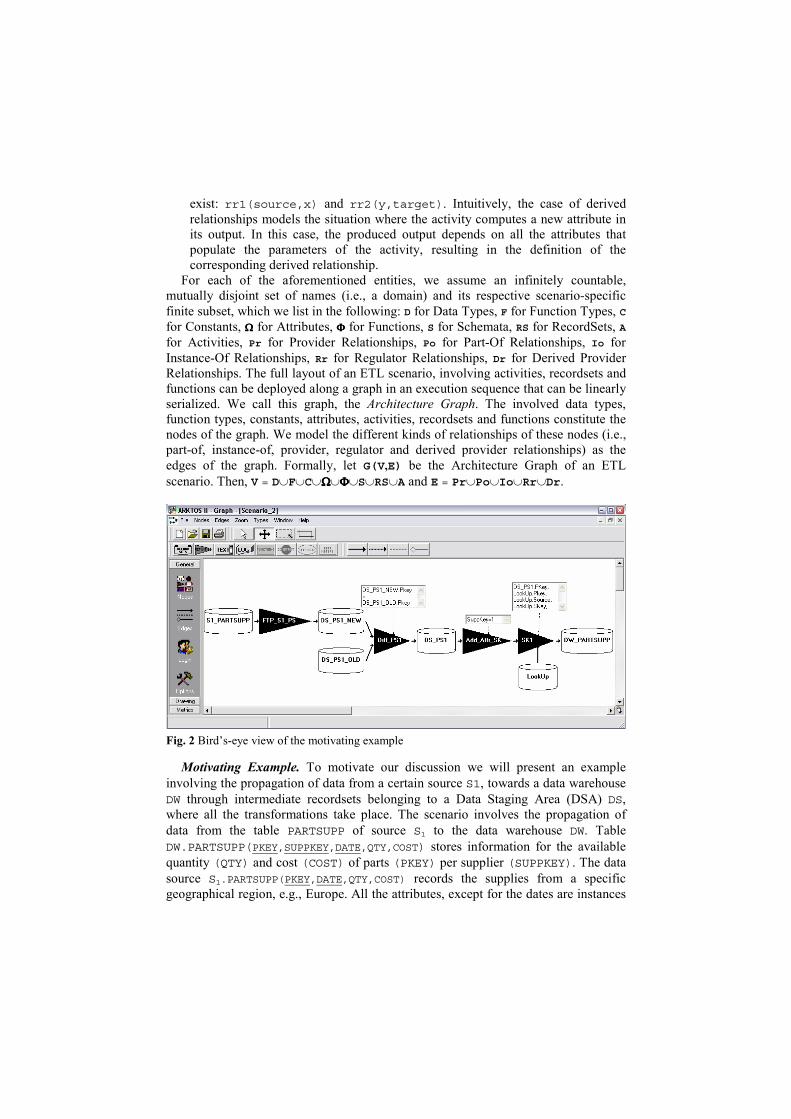
Fig. 2 Bird’s-eye view of the motivating example
Motivating Example. To motivate our discussion we will present an example involving the propagation of data from a certain source S1, towards a data warehouse DW through intermediate recordsets belonging to a Data Staging Area (DSA) DS, where all the transformations take place. The scenario involves the propagation of data from the table PARTSUPP of source S1 to the data warehouse DW. Table DW.PARTSUPP(PKEY,SUPPKEY,DATE,QTY,COST) stores information for the available quantity (QTY) and cost (COST) of parts (PKEY) per supplier (SUPPKEY). The data source S1.PARTSUPP(PKEY,DATE,QTY,COST) records the supplies from a specific geographical region, e.g., Europe. All the attributes, except for the dates are instances
of the Integer type. The scenario is graphically depicted in Fig. 2 and involves the following transformations.
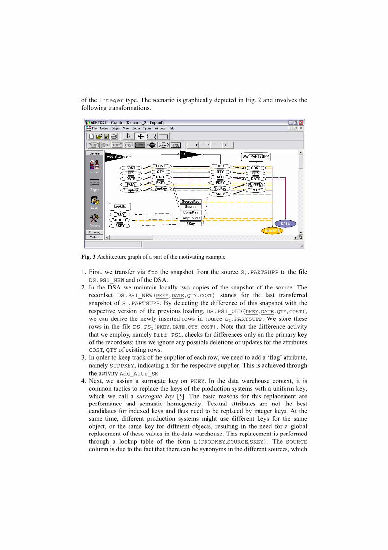
Fig. 3 Architecture graph of a part of the motivating example
1. First, we transfer via ftp the snapshot from the source S1.PARTSUPP to the file DS.PS1_NEW and of the DSA.
2. In the DSA we maintain locally two copies of the snapshot of the source. The recordset DS.PS1_NEW(PKEY,DATE,QTY,COST) stands for the last transferred snapshot of S1.PARTSUPP. By detecting the difference of this snapshot with the respective version of the previous loading, DS.PS1_OLD(PKEY,DATE,QTY,COST), we can derive the newly inserted rows in source S1.PARTSUPP. We store these rows in the file DS.PS1(PKEY,DATE,QTY,COST). Note that the difference activity that we employ, namely Diff_PS1, checks for differences only on the primary key of the recordsets; thus we ignore any possible deletions or updates for the attributes COST, QTY of existing rows.
3. In order to keep track of the supplier of each row, we need to add a ‘flag’ attribute, namely SUPPKEY, indicating 1 for the respective supplier. This is achieved through the activity Add_Attr_SK.
4. Next, we assign a surrogate key on PKEY. In the data warehouse context, it is common tactics to replace the keys of the production systems with a uniform key, which we call a surrogate key [5]. The basic reasons for this replacement are performance and semantic homogeneity. Textual attributes are not the best candidates for indexed keys and thus need to be replaced by integer keys. At the same time, different production systems might use different keys for the same object, or the same key for different objects, resulting in the need for a global replacement of these values in the data warehouse. This replacement is performed through a lookup table of the form L(PRODKEY,SOURCE,SKEY). The SOURCE column is due to the fact that there can be synonyms in the different sources, which
are mapped to different objects in the data warehouse. In our case, the activity that performs the surrogate key assignment for the attribute PKEY is SK1. It uses the lookup table LOOKUP(PKEY,SOURCE,SKEY). Finally, we populate the data warehouse with the output of the previous activity. In Fig. 3, which is a zoom-in in the last two activities of the scenario, we can
observe (from right to left): (i) the fact that the recordset DW.PARTSUPP comprises the attributes PKEY,SUPPKEY,DATE,QTY,COST (observe the UML-like notation with the diamond) (ii) the provider relationships (denoted as bold, solid arrows) between the output schema of the activity SK1 and the attributes of DW.PARTSUPP; (iii) the provider relationships between the input and the output schema of activity SK1; (iv) the provider relationships between the output schema of the activity Add_Attr_SK and the input schema of the activity SK1; (v) the population of the parameters of the surrogate key activity from regulator relationships (denoted as dotted bold arrows) by the attributes of table LOOKUP and some of the attribute of the input schema of SK1; (vi) the instance-of relationships (light dotted edges) between the attributes of the scenario and their data types (colored ovals at the bottom of the figure).
a1_in1(A_IN1_A1,A_IN1_A2,A_IN1_A3,A_IN1_A4)<- ds_ps1_new(A_IN1_A1,A_IN1_A2,A_IN1_A3,
A_IN1_A4).
a1_in2(A_IN2_A1,A_IN2_A2,A_IN2_A3,A_IN2_A4)<- ds_ps1_old(A_IN2_A1,A_IN2_A2,A_IN2_A3,
A_IN2_A4).
semi_join(A_OUT_A1,A_OUT_A2,A_OUT_A3,A_OUT_A4) <-
a1_in1(A_IN1_A1,A_IN1_A2,A_IN1_A3,A_IN1_A4),a1_in2(A_IN2_A1,_,_,_),A_OUT_A1=A_IN1_A1,A_OUT_A1=A_IN2_A1,A_OUT_A2=A_IN1_A2,A_OUT_A3=A_IN1_A3,A_OUT_A4=A_IN1_A4.
a1_out(A_OUT_A1,A_OUT_A2,A_OUT_A3,A_OUT_A4)<-a1_in1(A_IN1_A1,A_IN1_A2,A_IN1_A3,A_IN1_A4),~semi_join(A_IN1_A1,A_IN1_A2,A_IN1_A3,A_IN1_A4),
A_OUT_A1=A_IN1_A1,A_OUT_A2=A_IN1_A2,A_OUT_A3=A_IN1_A3,A_OUT_A4=A_IN1_A4.
ds_ps1(X1,X2,X3,X4) <-a_out(A_OUT_A1,A_OUT_A2,A_OUT_A3,A_OUT_A4),
X1=A_OUT_A1,X2=A_OUT_A2,X3=A_OUT_A3,X4=A_OUT_A4.
a2_in(A_IN_A1,A_IN_A2,A_IN_A3,A_IN_A4)<-ds_ps1(X1,X2,X3,X4),X1=A_IN_A1,X2=A_IN_A2,X3=A_IN_A3,X4=A_IN_A4.
a2_out(A_OUT_A1,A_OUT_A2,A_OUT_A3,A_OUT_A4,A_OUT_A5) <-
a2_in(A_IN_A1,A_IN_A2,A_IN_A3,A_IN_A4),A_OUT_A1=A_IN_A1,A_OUT_A2=A_IN_A2,A_OUT_A3=A_IN_A3,A_OUT_A4=A_IN_A4,A_OUT_A5='SOURCE1'.
a3_in(A_IN_A1,A_IN_A2,A_IN_A3,A_IN_A4,A_IN_A5) <-a2_out(A_OUT_A1,A_OUT_A2,A_OUT_A3,A_OUT_A4,
A_OUT_A5),A_OUT_A1=A_IN_A1,A_OUT_A2=A_IN_A2,A_OUT_A3=A_IN_A3,A_OUT_A4=A_IN_A4,A_OUT_A5=A_IN_A5.
a3_out(A_OUT_A1,A_OUT_A2,A_OUT_A3,A_OUT_A4,A_OUT_A5,A_OUT_A6)<-
a3_in(A_IN_A1,A_IN_A2,A_IN_A3,A_IN_A4,A_IN_A5),lookup(A_IN_A5,A_IN_A1,A_OUT_A6),A_OUT_A1=A_IN_A1,A_OUT_A2=A_IN_A2,A_OUT_A3=A_IN_A3,A_OUT_A4=A_IN_A4,A_OUT_A5=A_IN_A5.
dw_partsupp(X1,X2,X3,X4,X5,X6) <-a3_out(A_OUT_A1,A_OUT_A2,A_OUT_A3,A_OUT_A4,A_OUT_A5,A_OUT_A6).
LEGEND: a1: Diff_PS1 a2: Add_Attr_SK a3: SK1
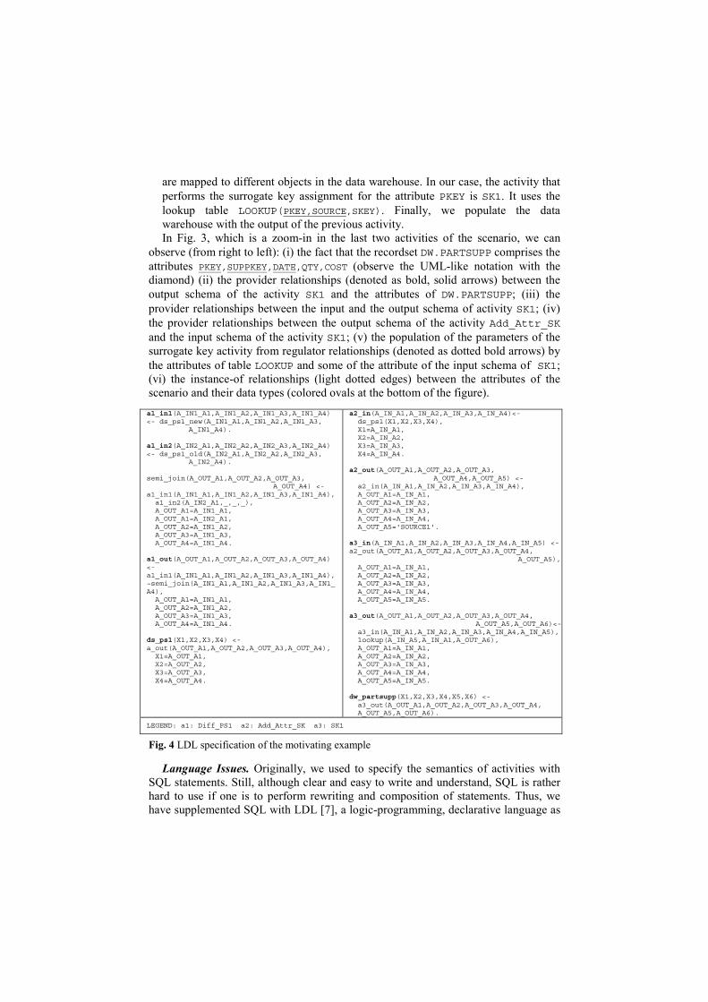
Fig. 4 LDL specification of the motivating example
Language Issues. Originally, we used to specify the semantics of activities with SQL statements. Still, although clear and easy to write and understand, SQL is rather hard to use if one is to perform rewriting and composition of statements. Thus, we have supplemented SQL with LDL [7], a logic-programming, declarative language as
the basis of our scenario definition. LDL is a Datalog variant based on a Horn-clause logic that supports recursion, complex objects and negation. In the context of its implementation in an actual deductive database management system, LDL++ [13], the language has been extended to support external functions, choice, aggregation (and even, user-defined aggregation), updates and several other features.
In general, there is a simple rule for constructing valid ETL scenarios in our setting. For each activity, the designer must provide three kinds of provider relationships: (a) a mapping of the activity's data provider(s) to the activity's input schema(ta); (b) a mapping of the activity's input schema(ta) to the activity's output, along with a specification of the semantics of the activity (i.e., the check / cleaning / transformation / value production that the activity performs), and (c) a mapping from the activity's output schema towards the data consumer of the activity. Several integrity constraints come along with this simple guideline; for lack of space we refer the interested reader to [10] for further insight. Fig. 4 shows the LDL program for our motivating example.
3. Templates for ETL activities
In this section, we will present the mechanism for exploiting template definitions of frequently used ETL activities. The general framework for the exploitation of these templates will be accompanied with the presentation of the language-related issues for template management and appropriate examples.
3.1 General Framework
Our philosophy during the construction of our metamodel was based on two pillars: (a) genericity, i.e., the derivation of a simple model, powerful to capture ideally all the cases of ETL activities and (b) extensibility, i.e., the possibility of extending the built-in functionality of the system with new, user-specific templates.
The genericity doctrine was pursued through the definition of a rather simple activity metamodel, as described in Section 2. Still, providing a single metaclass for all the possible activities of an ETL environment is not really enough for the designer of the overall process. A richer “language” should be available, in order to describe the structure of the process and facilitate its construction. To this end, we provide a palette of template activities, which are specializations of the generic metamodel class.
Observe Fig. 5 for a further explanation of our framework. The lower layer of Fig. 5, namely Schema Layer, involves a specific ETL scenario. All the entities of the Schema layer are instances of the classes Data Type, Function Type, Elementary Activity, RecordSet and Relationship. Thus, as one can see on the upper part of Fig. 5, we introduce a meta-class layer, namely Metamodel Layer involving the aforementioned classes. The linkage between the Metamodel and the Schema layers is achieved through instantiation (“InstanceOf”) relationships. The Metamodel layer implements the aforementioned genericity desideratum: the classes
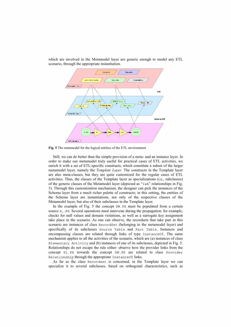
which are involved in the Metamodel layer are generic enough to model any ETL scenario, through the appropriate instantiation.
Fig. 5 The metamodel for the logical entities of the ETL environment
Still, we can do better than the simple provision of a meta- and an instance layer. In order to make our metamodel truly useful for practical cases of ETL activities, we enrich it with a set of ETL-specific constructs, which constitute a subset of the larger metamodel layer, namely the Template Layer. The constructs in the Template layer are also meta-classes, but they are quite customized for the regular cases of ETL activities. Thus, the classes of the Template layer as specializations (i.e., subclasses) of the generic classes of the Metamodel layer (depicted as “IsA” relationships in Fig. 5). Through this customization mechanism, the designer can pick the instances of the Schema layer from a much richer palette of constructs; in this setting, the entities of the Schema layer are instantiations, not only of the respective classes of the Metamodel layer, but also of their subclasses in the Template layer.
In the example of Fig. 5 the concept DW.PS must be populated from a certain source S1.PS. Several operations must intervene during the propagation: for example, checks for null values and domain violations, as well as a surrogate key assignment take place in the scenario. As one can observe, the recordsets that take part in this scenario are instances of class RecordSet (belonging to the metamodel layer) and specifically of its subclasses Source Table and Fact Table. Instances and encompassing classes are related through links of type InstanceOf. The same mechanism applies to all the activities of the scenario, which are (a) instances of class Elementary Activity and (b) instances of one of its subclasses, depicted in Fig. 5. Relationships do not escape the rule either: observe how the provider links from the concept S1.PS towards the concept DW.PS are related to class Provider
Relationship through the appropriate InstanceOf links. As far as the class Recordset is concerned, in the Template layer we can
specialize it to several subclasses, based on orthogonal characteristics, such as
whether it is a file or RDBMS table, or whether it is a source or target data store (as in Fig. 5). In the case of the class Relationship, there is a clear specialization in terms of the five classes of relationships which have already been mentioned in Section 2: Provider, Part-Of, Instance-Of, Regulator and Derived Provider.
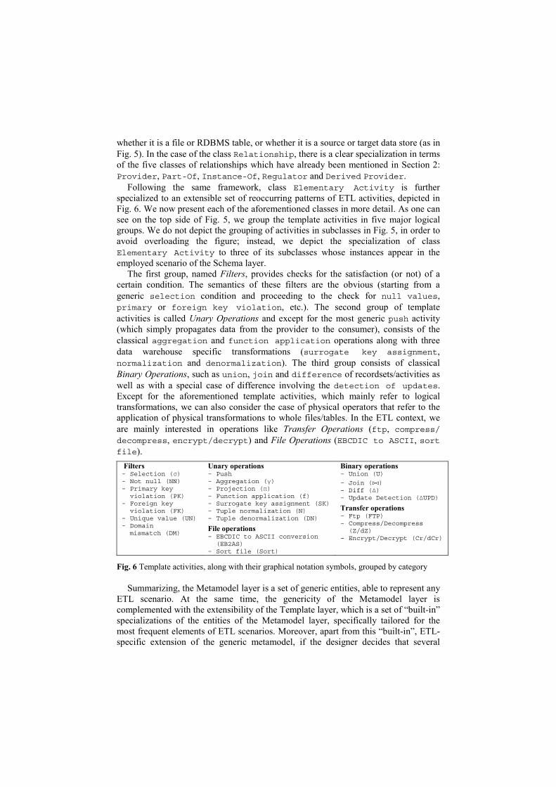
Following the same framework, class Elementary Activity is further specialized to an extensible set of reoccurring patterns of ETL activities, depicted in Fig. 6. We now present each of the aforementioned classes in more detail. As one can see on the top side of Fig. 5, we group the template activities in five major logical groups. We do not depict the grouping of activities in subclasses in Fig. 5, in order to avoid overloading the figure; instead, we depict the specialization of class Elementary Activity to three of its subclasses whose instances appear in the employed scenario of the Schema layer.
The first group, named Filters, provides checks for the satisfaction (or not) of a certain condition. The semantics of these filters are the obvious (starting from a generic selection condition and proceeding to the check for null values, primary or foreign key violation, etc.). The second group of template activities is called Unary Operations and except for the most generic push activity (which simply propagates data from the provider to the consumer), consists of the classical aggregation and function application operations along with three data warehouse specific transformations (surrogate key assignment, normalization and denormalization). The third group consists of classical Binary Operations, such as union, join and difference of recordsets/activities as well as with a special case of difference involving the detection of updates. Except for the aforementioned template activities, which mainly refer to logical transformations, we can also consider the case of physical operators that refer to the application of physical transformations to whole files/tables. In the ETL context, we are mainly interested in operations like Transfer Operations (ftp, compress/decompress, encrypt/decrypt) and File Operations (EBCDIC to ASCII, sortfile).
Filters - Selection (σ)- Not null (NN)- Primary key
violation (PK)- Foreign key
violation (FK)- Unique value (UN)- Domain
mismatch (DM)
Unary operations - Push- Aggregation (γ)- Projection (π)- Function application (f)- Surrogate key assignment (SK)- Tuple normalization (N)- Tuple denormalization (DN)
File operations - EBCDIC to ASCII conversion
(EB2AS)- Sort file (Sort)
Binary operations - Union (U)
- Join ()- Diff (∆)- Update Detection (∆UPD)
Transfer operations - Ftp (FTP)- Compress/Decompress
(Z/dZ)- Encrypt/Decrypt (Cr/dCr)
Fig. 6 Template activities, along with their graphical notation symbols, grouped by category
Summarizing, the Metamodel layer is a set of generic entities, able to represent any ETL scenario. At the same time, the genericity of the Metamodel layer is complemented with the extensibility of the Template layer, which is a set of “built-in” specializations of the entities of the Metamodel layer, specifically tailored for the most frequent elements of ETL scenarios. Moreover, apart from this “built-in”, ETL-specific extension of the generic metamodel, if the designer decides that several
‘patterns’, not included in the palette of the Template layer, occur repeatedly in his data warehousing projects, he can easily fit them into the customizable Template layer through a specialization mechanism.
3.2 Formal Definition and Usage of Template Activities
Once the template layer has been introduced, the obvious issue that is raised is its linkage with the employed declarative language of our framework. In general, the broader issue is the usage of the template mechanism from the user; to this end, we will explain the substitution mechanism for templates in this subsection and refer the interested reader to [12] for a presentation of the specific templates that we have constructed.
A Template Activity is formally defined as follows: − Name: a unique identifier for the template activity. − Parameter List: a set of names which act as regulators in the expression of the
semantics of the template activity. For example, the parameters are used to assign values to constants, create dynamic mapping at instantiation time, etc.
− Expression: a declarative statement describing the operation performed by the instances of the template activity. As with elementary activities, our model supports LDL as the formalism for the expression of this statement.
− Mapping: a set of bindings, mapping input to output attributes, possibly through intermediate placeholders. In general, mappings at the template level try to capture a default way of propagating incoming values from the input towards the output schema. These default bindings are easily refined and possibly rearranged at instantiation time.
The template mechanism we use is a substitution mechanism, based on macros, that facilitates the automatic creation of LDL code. This simple notation and instantiation mechanism permits the easy and fast registration of LDL templates. In the rest of this section, we will elaborate on the notation, instantiation mechanisms and template taxonomy particularities.
Notation. Our template notation is a simple language featuring four main
mechanisms for dynamic production of LDL expressions: (a) variables that are replaced by their values at instantiation time; (b) a function that returns the arity of an input, output or parameter schema; (c) loops, where the loop body is repeated at instantiation time as many times as the iterator constraint defines, and (d) keywords to simplify the creation of unique predicate and attribute names.
Variables. We have two kinds of variables in the template mechanism: parameter variables and loop iterators. Parameter variables are marked with a @ symbol at their beginning and they are replaced by user-defined values at instantiation time. A list of an arbitrary length of parameters can be defined with the notation @<parametername>[]. For such lists the user has to explicitly or implicitly provide their length at instantiation time. Loop iterators, on the other hand, are implicitly defined in the loop constraint. During each loop iteration, all the properly marked appearances of the iterator in the loop body are replaced by its current value (similarly to the way the C preprocessor treats #DEFINE statements). Iterators that appear marked in loop body
are instantiated even when they are a part of another string or of a variable name. We mark such appearances by enclosing them with $. This functionality enables referencing all the values of a parameter list and facilitates the creation an arbitrary number of pre-formatted strings.
Functions. We employ a built-in function, arityOf(<input/output/parameterschema>), which returns the arity of the respective schema, mainly in order to define upper bounds in loop iterators.
Loops. Loops are a powerful mechanism that enhances the genericity of the templates by allowing the designer to handle templates with unknown number of variables and with unknown arity for the input/output schemata. The general form of loops is [<simple constraint>] <loop body> where simple constraint has the form <lower bound> <comparison operator> <iterator> <comparison
operator> <upper bound>. Upper bound and lower bound can be arithmetic expressions involving arityOf() function calls, variables and constants. Valid arithmetic operators are +,-,/,* and valid comparison operators are <,>,=, all with their usual semantics. If lower bound is omitted, 0 is assumed. During each iteration, the loop body will be reproduced and the same time all the marked appearances of the loop iterator will be replaced by its current value, as described before. Loop nesting is permitted.
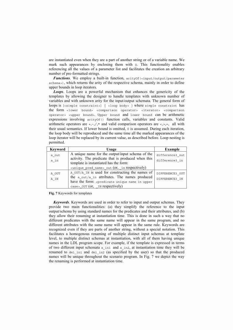
Keyword Usage Example a_out
a_in
A unique name for the output/input schema of the activity. The predicate that is produced when this template is instantiated has the form: <unique_pred_name>_out (or, _in respectively)
difference3_out
difference3_in
A_OUT
A_IN
A_OUT/A_IN is used for constructing the names of the a_out/a_in attributes. The names produced have the form: <predicate unique name in upper case>_OUT (or, _IN respectively)
DIFFERENCE3_OUT
DIFFERENCE3_IN
Fig. 7 Keywords for templates
Keywords. Keywords are used in order to refer to input and output schemas. They provide two main functionalities: (a) they simplify the reference to the input output/schema by using standard names for the predicates and their attributes, and (b) they allow their renaming at instantiation time. This is done in such a way that no different predicates with the same name will appear in the same program, and no different attributes with the same name will appear in the same rule. Keywords are recognized even if they are parts of another string, without a special notation. This facilitates a homogenous renaming of multiple distinct input schemas at template level, to multiple distinct schemas at instantiation, with all of them having unique names in the LDL program scope. For example, if the template is expressed in terms of two different input schemata a_in1 and a_in2, at instantiation time they will be renamed to dm1_in1 and dm1_in2 (as specified by the user) so that the produced names will be unique throughout the scenario program. In Fig. 7 we depict the way the renaming is performed at instantiation time.
Instantiation Mechanism. Template instantiation is the process where the user decides to pick a certain template and create a concrete activity out of it. This procedure requires that the user specifies the schemata of the activity and gives concrete values to the template parameters. Then, the process of producing the respective LDL description of the activity is easily automated. Instantiation order is important in our template creation mechanism, since, as it can easily been seen from the notation definitions, different orders can lead to different results. The instantiation order is as follows: 1. arityOf() functions and parameter variables appearing in loop boundaries are
calculated first; 2. loop productions are done by instantiating the appearances of the iterators; this
leads to intermediate results without any loops; 3. all the rest parameter variables are instantiated; 4. keywords are recognized and renamed.
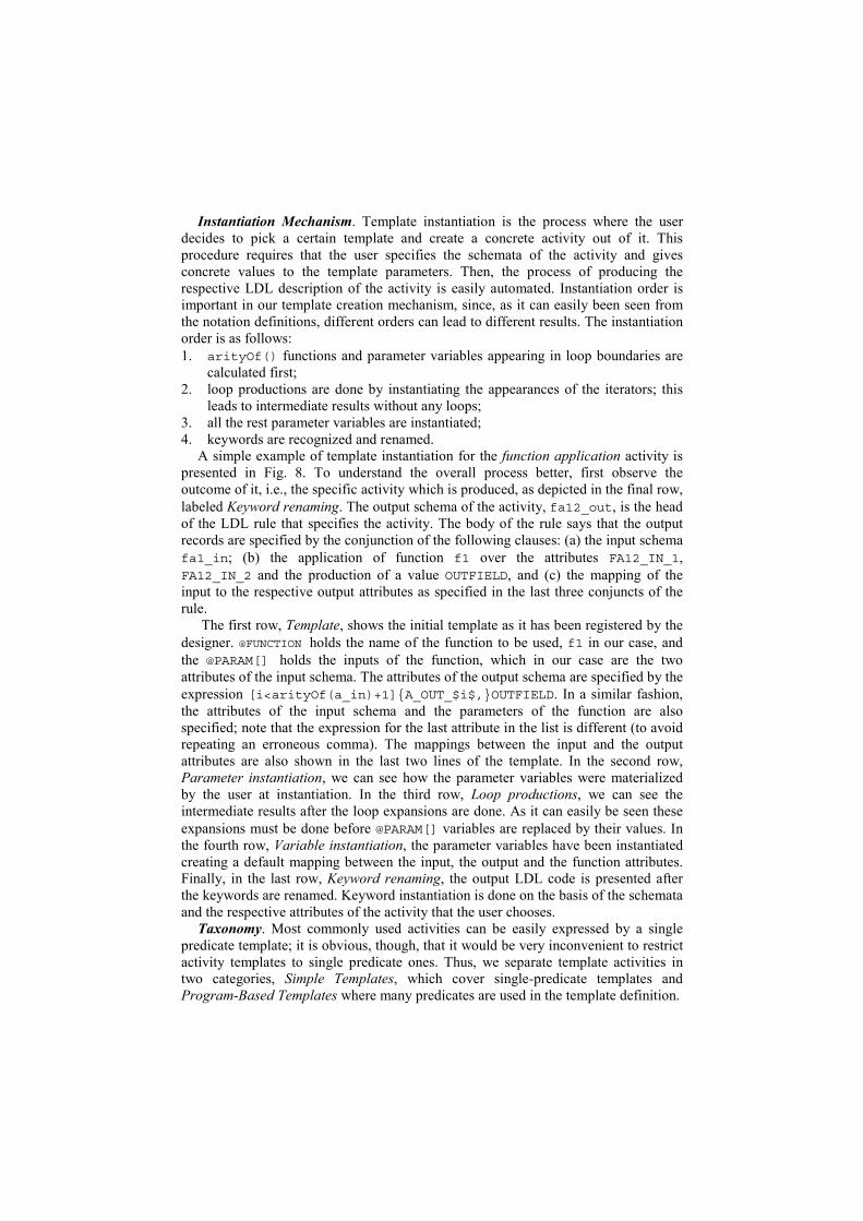
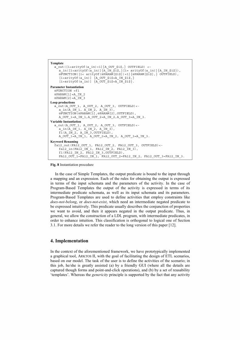
A simple example of template instantiation for the function application activity is presented in Fig. 8. To understand the overall process better, first observe the outcome of it, i.e., the specific activity which is produced, as depicted in the final row, labeled Keyword renaming. The output schema of the activity, fa12_out, is the head of the LDL rule that specifies the activity. The body of the rule says that the output records are specified by the conjunction of the following clauses: (a) the input schema fa1_in; (b) the application of function f1 over the attributes FA12_IN_1, FA12_IN_2 and the production of a value OUTFIELD, and (c) the mapping of the input to the respective output attributes as specified in the last three conjuncts of the rule.
The first row, Template, shows the initial template as it has been registered by the designer. @FUNCTION holds the name of the function to be used, f1 in our case, and the @PARAM[] holds the inputs of the function, which in our case are the two attributes of the input schema. The attributes of the output schema are specified by the expression [i<arityOf(a_in)+1]A_OUT_$i$,OUTFIELD. In a similar fashion, the attributes of the input schema and the parameters of the function are also specified; note that the expression for the last attribute in the list is different (to avoid repeating an erroneous comma). The mappings between the input and the output attributes are also shown in the last two lines of the template. In the second row, Parameter instantiation, we can see how the parameter variables were materialized by the user at instantiation. In the third row, Loop productions, we can see the intermediate results after the loop expansions are done. As it can easily be seen these expansions must be done before @PARAM[] variables are replaced by their values. In the fourth row, Variable instantiation, the parameter variables have been instantiated creating a default mapping between the input, the output and the function attributes. Finally, in the last row, Keyword renaming, the output LDL code is presented after the keywords are renamed. Keyword instantiation is done on the basis of the schemata and the respective attributes of the activity that the user chooses.
Taxonomy. Most commonly used activities can be easily expressed by a single predicate template; it is obvious, though, that it would be very inconvenient to restrict activity templates to single predicate ones. Thus, we separate template activities in two categories, Simple Templates, which cover single-predicate templates and Program-Based Templates where many predicates are used in the template definition.
Templatea_out([i<arityOf(a_in)+1]A_OUT_$i$, OUTFIELD) <-
a_in([i<arityOf(a_in)]A_IN_$i$,[i= arityOf(a_in)]A_IN_$i$),@FUNCTION([i< arityOf(@PARAM[$i$])+1]@PARAM[$i$], OUTFIELD),[i<arityOf(a_in)] A_OUT_$i$=A_IN_$i$,[i=arityOf(a_in)] A_OUT_$i$=A_IN_$i$.
Parameter Instantiation @FUNCTION =f1@PARAM[1]=A_IN_2@PARAM[2]=A_IN_3
Loop productionsa_out(A_OUT_1, A_OUT_2, A_OUT_3, OUTFIELD)<-
a_in(A_IN_1, A_IN_2, A_IN_3),@FUNCTION(@PARAM[1],@PARAM[2],OUTFIELD),A_OUT_1=A_IN_1,A_OUT_2=A_IN_2,A_OUT_3=A_IN_3.
Variable Instantiationa_out(A_OUT_1, A_OUT_2, A_OUT_3, OUTFIELD)<-
a_in(A_IN_1, A_IN_2, A_IN_3),f1(A_IN_2, A_IN_3,OUTFIELD),A_OUT_1=A_IN_1, A_OUT_2=A_IN_2, A_OUT_3=A_IN_3.
Keyword Renamingfa12_out(FA12_OUT_1, FA12_OUT_2, FA12_OUT_3, OUTFIELD)<-
fa12_in(FA12_IN_1, FA12_IN_2, FA12_IN_3),f1(FA12_IN_2, FA12_IN_3,OUTFIELD),FA12_OUT_1=FA12_IN_1, FA12_OUT_2=FA12_IN_2, FA12_OUT_3=FA12_IN_3.
Fig. 8 Instantiation procedure
In the case of Simple Templates, the output predicate is bound to the input through a mapping and an expression. Each of the rules for obtaining the output is expressed in terms of the input schemata and the parameters of the activity. In the case of Program-Based Templates the output of the activity is expressed in terms of its intermediate predicate schemata, as well as its input schemata and its parameters. Program-Based Templates are used to define activities that employ constraints like does-not-belong, or does-not-exist, which need an intermediate negated predicate to be expressed intuitively. This predicate usually describes the conjunction of properties we want to avoid, and then it appears negated in the output predicate. Thus, in general, we allow the construction of a LDL program, with intermediate predicates, in order to enhance intuition. This classification is orthogonal to logical one of Section 3.1. For more details we refer the reader to the long version of this paper [12].
4. Implementation
In the context of the aforementioned framework, we have prototypically implemented a graphical tool, ARKTOS II, with the goal of facilitating the design of ETL scenarios, based on our model. The task of the user is to define the activities of the scenario; in this job, he/she is greatly assisted (a) by a friendly GUI (where all the details are captured though forms and point-and-click operations), and (b) by a set of reusability ‘templates’. Whereas the genericity principle is supported by the fact that any activity
of our model can be tailored by the user, the customization principle is supported by the reusability templates. The notion of ‘template’ is in the heart of ARKTOS II, and there are templates for practically every aspect of the model: data types, functions and activities. Templates are extensible, thus providing the user with the possibility of customizing the environment according to his/her own needs. Especially for activities, which form the core of our model, we provide a specific menu with a set of frequently used ETL Activities. Moreover, the system assists the user in several ways: apart from the friendly GUI (Fig. 2), ARKTOS II offers zoom-in/zoom-out capabilities (a particularly useful feature in the construction of the data flow of the scenario through inter-attribute ‘provider’ mappings –see also Fig. 2 and 3) and automatic consistency checks for the completeness and integrity of the design. A distinctive feature of ARKTOS II is the computation of the scenario’s design quality by employing a set of metrics [10] either for the whole scenario or for each activity of it.
The scenarios are stored in ARKTOS II repository (implemented in a relational DBMS); the system allows the user to store, retrieve and reuse existing scenarios. All the metadata of the system involving the scenario configuration, the employed templates and their constituents are stored in the repository. The choice of a relational DBMS for our metadata repository allows its efficient querying as well as the smooth integration with external systems and/or future extensions of ARKTOS II.
We have implemented ARKTOS II with Oracle 8.1.7 as basis for our repository and Ms Visual Basic (Release 6) for developing our GUI. The connectivity to source and target data stores is achieved through ODBC connections and the tool offers an automatic reverse engineering of their schemata.
5. Related Work
There is a variety of ETL tools in the market; we mention a recent review [1] and several commercial tools [3,4,6,8]. Research prototypes include the AJAX data cleaning tool [2] and the Potter’s Wheel system [9]. These two research prototypes are based on algebras, which we find specifically tailored for the case of homogenizing web data. Clearly, ARKTOS II is a design tool; still, with respect to the design capabilities of the aforementioned approaches, our technique contributes (a) by offering an extensible framework though a uniform extensibility mechanism, and (b) by providing formal foundations to allow the reasoning over the constructed ETL scenarios. Finally, we should refer the interested reader to [10] for a detailed presentation of ARKTOS II model. The model is accompanied by a set of importance metrics where we exploit the graph structure to measure the degree to which activities/recordsets/attributes are bound to their data providers or consumers. In [11] we propose a complementary conceptual model for ETL scenarios.
6. Conclusions
In this paper, we have focused on the data-centric part of logical design of the ETL scenario of a data warehouse. First, we have defined a formal logical Metamodel as a
logical abstraction of ETL processes. The data stores, activities and their constituent parts, as well as the provider relationships that map data producers to data consumers have formally been defined. Then, we have provided a reusability framework that complements the genericity of the aforementioned Metamodel. Practically, this is achieved from an extensible set of specializations of the entities of the Metamodel layer, specifically tailored for the most frequent elements of ETL scenarios, which we call template activities. Finally, we have presented a graphical design tool, ARKTOS II, with the goal of facilitating the design of ETL scenarios, based on our model.
As future work, we already have preliminary results for the optimization of ETL scenario under certain time and throughput constraints. A set of loosely coupled tools is also under construction for the purposes of optimization of the execution of ETL scenarios.
References
[1] Gartner. ETL Magic Quadrant Update: Market Pressure Increases. Available at http://www.gartner.com/reprints/informatica/112769.html
[2] H. Galhardas, D. Florescu, D. Shasha and E. Simon. Ajax: An Extensible Data Cleaning Tool. In Proc. ACM SIGMOD Intl. Conf. On the Management of Data, pp. 590, Dallas, Texas, (2000).
[3] IBM. IBM Data Warehouse Manager. Available at http://www-3.ibm.com/software/ data/db2/datawarehouse/
[4] Informatica. PowerCenter. Available at http://www.informatica.com/products/data+ integration/powercenter/default.htm
[5] R. Kimbal, L. Reeves, M. Ross, W. Thornthwaite. The Data Warehouse Lifecycle Toolkit: Expert Methods for Designing, Developing, and Deploying Data Warehouses. John Wiley & Sons, February 1998.
[6] Microsoft. Data Transformation Services. Available at www.microsoft.com [7] S. Naqvi, S. Tsur. A Logical Language for Data and Knowledge Bases. Computer
Science Press 1989. [8] Oracle. Oracle Warehouse Builder Product Page. Available at http://otn.oracle.com/
products/warehouse/content.html [9] V. Raman, J. Hellerstein. Potter's Wheel: An Interactive Data Cleaning System. In
Proceedings of 27th International Conference on Very Large Data Bases (VLDB), pp. 381-390, Roma, Italy, (2001).
[10] P. Vassiliadis, A. Simitsis, S. Skiadopoulos. Modeling ETL Activities as Graphs. In Proc. 4th Intl. Workshop on Design and Management of Data Warehouses (DMDW), pp. 52–61, Toronto, Canada, (2002).
[11] P. Vassiliadis, A. Simitsis, S. Skiadopoulos. Conceptual Modeling for ETL Processes. In Proc. 5th ACM Intl. Workshop on Data Warehousing and OLAP (DOLAP), pp. 14–21, McLean, Virginia, USA (2002).
[12] P. Vassiliadis, A. Simitsis, P. Georgantas, M. Terrovitis. A Framework for the design of ETL scenarios (long version). Available at http://cs.uoi.gr/~pvassil/publications/ caise03_long.pdf
[13] C. Zaniolo. LDL++ Tutorial. UCLA. http://pike.cs.ucla.edu/ldl/, Dec. 1998.