a framework for it service management integration - kokoelmat
TRANSCRIPT

LAPPEENRANTA UNIVERSITY OF TECHNOLOGY
School of Industrial Engineering and Management
Department of Software Engineering and Information Management
A FRAMEWORK FOR IT SERVICE MANAGEMENT
INTEGRATION
Examiners: Professor Kari Smolander
MSc Jori Kanerva
Supervisor: MSc Jori Kanerva
Vantaa, October 7th, 2013
Jussi Saukkonen

ii
ABSTRACT
Lappeenranta University of Technology
School of Industrial Engineering and Management
Department of Software Engineering and Information Management
Jussi Saukkonen
Master’s Thesis
2013
82 pages, 15 figures, 4 tables and 4 appendices
Examiners: Professor Kari Smolander
MSc Jori Kanerva
Keywords: IT Service Management, ITIL, integration, process, architecture
The objective of this Master’s Thesis is to find out best practices for IT service manage-
ment integration. Integration in this context means process integration between an IT or-
ganization and an integration partner. For observing the objective, two different perspec-
tives are assigned: process and technology. The thesis consists of theory, framework, im-
plementation, and analysis parts. The first part introduces common methodology of IT
service management and enterprise integration. The second part presents an integration
framework for ITSM integration. The third part illustrates how the framework is used and
the last part analyses the framework.
The major results of this thesis were the framework architecture, the framework tools, the
implementation model, the testing model, and the deployment model for ITSM integra-
tion. As a fundamental best practice, the framework contained a four-division structure
between architecture, process, data, and technology. This architecture provides a baseline
for ITSM integration design, implementation and testing.
iii
TIIVISTELMÄ
Lappeenrannan teknillinen yliopisto
Tuotantotalouden tiedekunta
Ohjelmistotuotannon ja tiedonhallinan osasto
Jussi Saukkonen
Diplomityö
2013
82 sivua, 15 kuvaa, 4 taulukkoa ja 4 liitettä
Tarkastajat: Professori Kari Smolander
DI Jori Kanerva
Hakusanat: IT-palvelunhallinta, ITIL, integraatio, prosessi, arkkitehtuuri
Tämän diplomityön tavoitteena on tuoda esille IT-palvelunhallinnan integraatioiden
parhaita käytäntöjä. Integraatiolla tarkoitetaan tässä yhteydessä IT-organisaation ja
integraatiokumppanin välistä prosessi-integraatiota. Työssä on valittu kaksi näkökulmaa
tavoitteen tutkimiseksi: prosessi- ja teknologianäkökulma, jonka lisäksi diplomityö on
jaettu teoria-, viitekehys-, toteutus- ja analyysi-osioihin. Työn ensimmäinen osa esittelee
IT-palvelunhallinnan ja yritysintegraatioiden yleistä metodologiaa. Toinen osa keskittyy
kuvaamaan työn tuloksena syntyneen IT-palvelunhallinan integraatioiden viitekehyksen.
Kolmannessa osassa annetaan esimerkkejä viitekehyksen käytöstä ja neljännessä osassa
analysoidaan viitekehystä.
Työn tärkeimmät tulokset olivat viitekehyksen arkkitehtuuri, viitekehyksen työkalut,
toteutusmalli, testausmalli ja käyttöönottomalli IT-palvelunhallinnan integraatioille.
Tärkeimpänä parhaana käytäntönä nousi esille integraatioiden nelikenttä, joka koostui
arkkitehtuuri-, prosessi-, data- ja teknologiaosasta. Tämä arkkitehtuuri kuvaa
perusrakenteen ja lähtötason integraatioiden suunnittelulle, toteutukselle ja testaukselle.

1
TABLE OF CONTENTS
1. INTRODUCTION .................................................................................................. 6
1.1. Background ...................................................................................................... 6 1.2. Problem Description and Scope ..................................................................... 7 1.3. Methods .......................................................................................................... 10
1.4. Structure of the Thesis .................................................................................. 10
2. INTRODUCTION TO IT SERVICE MANAGEMENT .................................. 12
2.1. What Is a Service? ......................................................................................... 12 2.2. ITIL Best Practice Framework .................................................................... 15 2.3. ISO/IEC 20000 Standard .............................................................................. 20
3. ENTERPRISE INTEGRATION METHODOLOGY ...................................... 22
3.1. Short History of Enterprise Integration ..................................................... 22 3.2. Enterprise Integration Concepts ................................................................. 23
3.3. Integration Approach ................................................................................... 26
3.4. Integration Architecture ............................................................................... 29 3.5. Communication Channel .............................................................................. 29 3.6. Communication Interface ............................................................................. 30
3.7. Data Transformation .................................................................................... 31 3.8. Technical Interoperability Recommendations ........................................... 34
4. IT SERVICE MANAGEMENT PROCESS INTEGRATION ........................ 38
4.1. ITIL Recommendation ................................................................................. 39 4.2. Design ............................................................................................................. 40
4.3. Implementation ............................................................................................. 42
4.4. Transition to Production .............................................................................. 44 4.5. Other Considerations .................................................................................... 46
5. FRAMEWORK FOR SERVICE MANAGEMENT INTEGRATION ........... 49
5.1. Framework Development ............................................................................. 49 5.2. Framework Structure ................................................................................... 51 5.3. Framework Tools .......................................................................................... 58
5.4. Framework Deployment ............................................................................... 62
6. ANALYSIS OF INTEGRATION FRAMEWORK .......................................... 65
6.1. Comparison with Initial Requirements ....................................................... 65 6.2. Benefits ........................................................................................................... 68 6.3. Development Areas ....................................................................................... 69
7. CONCLUSIONS .................................................................................................. 72
7.1. Evaluation of Results .................................................................................... 73
7.2. Exploitation of Results .................................................................................. 75 7.3. Future ............................................................................................................. 76
REFERENCES ............................................................................................................. 78
APPENDICES

2
ABBREVIATIONS
AOP Aspect-Oriented Programming
API Application Programming Interface
B2Bi Business-to-Business Integration
BAM Business Activity Monitoring
BI Business Intelligence
BPEL Business Process Execution Language
BPM Business Process Management
BPMN Business Process Modeling Notation
CMMI Capability Maturity Model Integration
CSI Continuous Service Improvement
CSV Comma Separated Value
EA Enterprise Architecture
EAI Enterprise Application Integration
EDI Electronic Data Interchange
EI Enterprise Integration
ERP Enterprise Resource Planning
ESB Enterprise Service Bus
ETL Extract-Transform-Load
FTP File Transfer Protocol
HTTP Hypertext Transfer Protocol
HTTPS Hypertext Transfer Protocol Secure
ICT Information and Communication Technology
ITIL Information Technology Infrastructure Library
ITM Information Technology Management
ITSM Information Technology Service Management
itSMF IT Service Management Forum
JDBC Java Database Connectivity
JSON JavaScript Object Notation
MOM Message-Oriented Middleware
OASIS Organization for the Advancement of Structured Information Standards
ODBC Open Database Connectivity
OLA Operational Level Agreement
OMG Object Management Group
PaaS Platform as a Service
REST REpresentational State Transfer
SaaS Software as a Service
SLA Service Level Agreement
SLM Service Level Management
SOA Service Oriented Architecture
SOAP Simple Object Access Protocol
SOI Service Oriented Integration
SSL Secure Sockets Layer
TOGAF The Open Group Architecture Framework
TLS Transport Layer Security
UAT User Acceptance Test
UDDI Universal Description Discovery and Integration

3
UI User Interface
W3C World Wide Web Consortium
WSBPEL Web Services Business Process Execution Language
WSDL Web Service Definition Language
XML Extensible Markup Language

4
LIST OF FIGURES
Figure 1: Thesis Framework ............................................................................................. 9 Figure 2: Thesis Process ................................................................................................. 10
Figure 3: ITIL Service Lifecycle..................................................................................... 16 Figure 4: Service Lifecycle Management ....................................................................... 18 Figure 5: ITIL Incident Management Process ................................................................ 19 Figure 6: EI Timeline ...................................................................................................... 23 Figure 7: EI Approaches ................................................................................................. 27
Figure 8: Information Levels .......................................................................................... 32 Figure 9: ITSM Process Integration Parts ....................................................................... 38 Figure 10: ITIL Technology Management Recommendation ........................................ 39 Figure 11: Integration Framework Development Process .............................................. 50
Figure 12: Integration Framework Structure .................................................................. 52 Figure 13: Implementation Model for ITSM Integration ................................................ 55 Figure 14: Testing Model for ITSM Integration ............................................................. 57
Figure 15: Deployment Model of the Integration Framework ........................................ 63

5
LIST OF TABLES
Table 1: IT Service Contexts........................................................................................... 13 Table 2: Interoperability Recommendations for B2Bi .................................................... 35
Table 3: Integration Framework Development Requirements ........................................ 51 Table 4: Integration Framework Tools ........................................................................... 58

6
1. INTRODUCTION
1.1. Background
During recent decades organizations have improved automation utilizing information and
communication technologies (ICT). This change has shifted people from manufacturing
industries to service industries (Chesbrough & Spohrer 2006, 36). Nowadays, Infor-
mation Technology (IT) is not anymore just hardware, systems, software, and PCs. IT
can be seen more of a services domain. (van Bon et al. 2007b, 14)
IT Service Management (ITSM) is a part of service sciences which is a mixture of com-
puter science, operations research, industrial engineering, business strategy, management
sciences, social and cognitive sciences, and organizational theory (Galup et al. 2009, 124).
The main purpose of ITSM is to align business requirements to IT services and deliver
services to organizations (Deutscher & Felden 2010, 167). ITSM was earlier perceived
as service-oriented Information Technology Management (ITM) which focused on infra-
structure management from process point of view. However, this thinking has changed
towards process and customer-orientation during the last decade. Now, the term ITSM
has established its position as a distinct discipline and its main objective is to contribute
quality to IT services. (van Bon et al. 2007b, 17)
Frameworks and standards provide a baseline for ITSM implementations. One of the best
known frameworks is ITIL. It originally stood for the Information Technology Infrastruc-
ture Library but this definition can no longer be found in the new ITIL books since the
current scope of ITIL is not anymore limited to the infrastructure. ITIL provides both best
practices for ITSM and also a set of integrated processes (van Bon et al. 2008, 31). In
addition to ITIL, there are other important ITSM frameworks such as Capability Maturity
Model Integration (CMMI), COBIT and Six Sigma. CMMI integrates different software
engineering maturity models into one framework. COBIT organizes IT capabilities, per-
formance and risks into a unified structure which helps in evaluation, implementation and
understanding. Six Sigma aims at improving IT process capabilities and decreasing pro-
cess variation with the use of measurement tools. The first international standard of ITSM,

7
ISO 20000, provides an integrated process approach for delivering managed services to
both business and customers (van Bon et al. 2008, 31-32). Each framework emphasizes
different aspects, even though they can be used jointly.
ITSM processes can be integrated through different perspectives. One perspective is to
integrate an ITSM process with other ITSM processes. In fact, this is what ITIL tends to
do. Another perspective, which is also supported by ITIL, is to integrate ITSM processes
within an organization. The target of this perspective is to change the ways people are
working. More technical integration perspective is Enterprise Integration (EI) which sup-
ports the expansion of ITSM processes over the organizational boundaries. This kind of
approach has been paid less attention. Therefore, the EI approach for ITSM process inte-
gration was chosen to this thesis to be observed more thoroughly.
In addition to the theoretical need, this thesis has also a practical motivator. The integra-
tion problems faced in the everyday work at Sofigate Oy have created a real need for
general integration model that guides through the ITSM process integration projects from
design to deployment, and provides best practices from process and technology wise.
Sofigate Oy was founded in 2003 and it is specialized in ICT management and develop-
ment providing different types of ICT management services. The services vary from ICT
expert and development services to full services which provide comprehensive ICT man-
agement on a turnkey basis. The company consists of over 100 employees and the turno-
ver in 2012 was 16.1 million Euros. (Sofigate 2013)
1.2. Problem Description and Scope
This thesis targets to find out best practices for the communication between an IT organ-
ization and an integration partner. More specifically, this communication takes place be-
tween ITSM systems and it can be referred to integration. However, the term integration
in this context could be easily mixed up with the system integration. Therefore the word
“communication” illustrates the scope better.

8
The need for integration has existed since the development of enterprise systems. Today,
this need still remains and according to Zhang et al. (2009) modern organizations have
built up their IT relying on distributed applications, tools, and systems. These complex
environments comprise of dispersed resources which require collaboration among each
other.
A lot of studies have been made focusing on implementation and integration of ITSM
processes in organizations. However, these studies mainly focus on the business and pro-
cess point of view and a clear technical perspective is missing. On the other hand, other
studies have been exploring technical requirements for ITSM process integrations inside
organizations. These studies provide good technical knowledge about the technology and
requirements but the higher level picture is missing. This thesis aims to fill this gap by
observing ITSM process integration from both business and technology aspects.
Specific ITSM processes, for example incident and change management processes, are
frequently extended outside organizational boundaries. This means that the external inte-
gration partner is a part of the end-to-end process. A good example is a service desk
function which is often outsourced. Therefore, a basic scenario would be to build up in-
tegration for incident management between IT organization’s ITSM system and integra-
tion partner’s ITSM system. This kind of integration automates the communication and
reduces manual work. Additionally, the integration provides more effective reporting and
monitoring capabilities from the IT organization perspective. This is because tickets are
recorded into database with timestamp, categorization and other relevant information
which can be later used for reporting.
As a limitation, this thesis focuses only on ticket integrations between an IT organization
and an external integration partner using incident management as a reference solution.
The word ticket integration in this context refers to integrations which are transactional
by nature and consist of nearly real-time messages. To give an example, incidents, service
requests, change requests and problems can be considered as tickets in the ITIL context.
One more limitation is that this thesis does not focus on Application Programming Inter-
face (API) development in a code level since the focus is more on architectural level.

9
Derived from the previous discussion, this thesis consists of two main research questions.
The main research questions are presented as follows:
1. What are the best practices for integrating an ITSM process with an integration part-
ner?
2. How integration interfaces should be built to support the interoperability and the
ease at maintenance?
The thesis framework illustrates the focus areas and interdependency between the re-
search questions. The framework is presented in the figure 1.
Figure 1: Thesis Framework
The purpose of the first research question is to address good and generally accepted ways
of building integrations between IT organizations and integration partners. Integration in
this context means automatic message exchange between communication interfaces over
the Internet. More specifically, the research question examines an end-to-end integration
process from IT organization to the integration partner. The second research question
looks integrations from more technical perspective. It focuses on finding the best ways of
designing and implementing integration interfaces with interoperability in mind. It also
observes recommended techniques and methods for integration.

10
1.3. Methods
This thesis is divided into four parts which are theory, framework, implementation and
analysis. The theory part introduces common methodology of ITSM and EI. The frame-
work part summarizes the findings from theory part and combines them with researcher’s
practical knowledge. As a result a generic framework is created which describes integra-
tion best practices and provides different viewpoints that cover integrations comprehen-
sively. This newly created framework is then used to design an ITSM process integration.
This step represents the implementation part and takes the theory into practice. The final
part of the thesis analyzes the framework outcome. These previously discussed parts are
presented in the figure 2 as a process.
Figure 2: Thesis Process
This process is organized so that it can be classified to the action research. Crowther &
Lancaster (2012) describe action research as an approach that solves practical problems
with the help of researcher’s involvement. Following characteristics give a better insight
of this approach: problem-centered, participative, cyclical, co-operative, and profession-
ally developing. Most notably, a researcher implements solutions to outlined problems
and analyzes outcomes. The process is cyclical which means that the researcher continu-
ously improves the solution based on the feedback and evaluations. Furthermore, action
research focuses on developing individuals instead of scientific knowledge.
1.4. Structure of the Thesis
The structure of this thesis consists of seven chapters. The first chapter introduces the
background, the research problem and the methods used in this thesis. Generally, the first
chapter gives an overall picture what this thesis is all about. The remaining chapters are
categorized to theory, practice, and review.
Theory FrameworkImplemen-
tationAnalysis

11
The second and the third chapter are theory chapters. The second chapter gives an over-
view of ITSM and related concepts. Furthermore, its purpose is to give background in-
formation for the first research question. In regard to the scope of the thesis, the second
chapter focuses only on the incident management. Therefore, all ITSM processes are not
comprehensively dealt with. The third chapter presents technical methodology needed to
extensively answer to the second research question. More precisely, the third chapter in-
troduces EI, Service-Oriented Architecture (SOA) and data integration. In addition, the
chapter discusses about the history of EI and the current state-of-the-art interoperability
recommendations in the EI landscape.
The chapters four and five are related to the integration framework and provide practical
knowledge about ITSM process integrations. The purpose of the fourth chapter is to ob-
serve ITSM process integrations from both process and technical perspective. At the same
time it presents researcher’s practical experiences about ITSM integrations. The fifth
chapter focuses on describing the integration framework. It presents the framework ar-
chitecture, implementation, testing and deployment models. After this the chapter demon-
strates how the framework tools are used to build an ITSM integration design.
The outcome of the integration framework is analyzed in the chapter six. The chapter
evaluates the usefulness of the framework, discusses about benefits gained from the inte-
gration framework utilization, and highlights the development areas of the framework.
The seventh chapter concludes the thesis by answering to the research questions. This
chapter also presents the found results and evaluates how the results are linked to the
theory. After this the chapter discusses about exploitation of results and, finally, ends the
discussion with future trends and visions.

12
2. INTRODUCTION TO IT SERVICE MANAGEMENT
ITSM is about designing, implementing, developing, supporting and managing IT ser-
vices. The core parts are service itself and service quality which are managed utilizing
best practice frameworks and standards, such as ITIL and ISO/IEC 20000.
This chapter begins with introduction of services, and continues describing ITIL frame-
work and ISO 20000 standard. The last part of this chapter drills deeper in ITSM tech-
nology aspect and service integration. The chapter combines business and technology
from ITSM perspective.
2.1. What Is a Service?
A fundamental part of ITSM is services which create the foundation for different opera-
tions and activities. Service contexts, layers and quality are the core attributes that de-
scribe services.
Service Definition and Context
A service can have multiple contexts. Following service definitions blur the line between
business and technology.
“A service is a means of delivering value to customers by facilitating outcomes
customers want to achieve without the ownership of specific costs and risks.” (OGC
2007b, 11)
“An IT service is a service provided to one or more customers by an IT service
provider. An IT service is based on the use of IT and supports the customer’s busi-
ness processes. An IT service is made up from a combination of people, processes
and technology and should be defined in a Service Level Agreement.” (van Bon et
al. 2007b, 19):

13
“A service is a unit of solution logic to which service-orientation has been applied
to a meaningful extent. It is the application of service-orientation design principles
that distinguishes a unit of logic as a service compared to units of logic that may
exist solely as objects or components.” (Erl 2008a, 37)
As the different definitions of a service state, usage of the service depends on the context.
Table 1 presents IT service contexts derived from the definitions and brings out the ob-
jectives of each context.
Table 1: IT Service Contexts
Context Objective
Business Value creation
Process Supporting business processes
Technology Providing logical functionality
The business context rises up value creation while the technology context sees services
as logical components. The process context ties the service to organization’s processes
and connects the service as a part of process network. All in all, services have common
denominator in spite of the context; someone or something uses them whether it is a hu-
man or a computer.
Service Layers
Services are usually seen as larger entities. One example of this is IT device order service.
Services of this size can wrap smaller subservices inside them or utilize other underlying
services, such as billing or integration services. Therefore size of a service depends on
the layer on which the service is examined. For example, if IT device order service is
implemented in an ITSM system, it should be examined on business layer as it is business
related.

14
Services follow certain process which contains different steps called activities. The activ-
ities should be examined on the process layer. If the service structure is explored even in
more detail, one can see that outputs of different activities in the process act as triggers.
If this process is implemented in ITSM system, triggers fire execution of certain technical
functionalities which can consist of scripts, database field changes, or other changes in
the system. In fact, one example of a technical functionality is a web service which can
send and receive data from one point to another over the Internet. When the service is
inspected from end user point of view to the code level, one can notice that it is not ideal
to present all information at once, especially for all different target groups. At this point,
service layers come in. One layer is used for presenting information, one for handling
process activities, and one for executing technical functionalities.
Service Quality
Without proper quality of services, services could not be valued by business (van Bon et
al. 2008, 1). Therefore, quality is more than a result of a technical attribute; it is a rela-
tionship with a service consumer (van Bon et al. 2007b, 35).
According to van Bon et al. (2008), following attributes of an IT service can be used to
measure quality:
- Availability
- Capacity
- Performance
- Security
- Confidentiality
- Scalability
- Adjustability
- Portability
All of these attributes measure IT service as a component. However, van Bon et al.
(2007b) see that a characteristic of modern ITSM is an end-to-end approach which means
that service quality is measured at consumer’s level and not on component level. Taking
this into account in design phase will lead building IT services from customer-oriented

15
aspect instead of technology-oriented aspect. In practice, end-to-end approach means that
IT services are measured both at component and end user levels. For example, end users
could be asked: How they feel about the service? If the service has worked well at the
component level but external factors, such as difficulties in integration, have affected to
the end-to-end functioning of the service, then the overall feeling might not be good.
Therefore, constant measuring is needed on all the service levels.
Service Level Management (SLM) process defines, monitors, and reports about the ob-
jectives of an IT service. SLM provides valuable information for an IT organization and
integration partner about current status of the service. It also ensures that actions are taken
when they are needed. An agreement that describes targets and responsibilities between
IT organization and integration partner is called as Service Level Agreement (SLA). The
agreement directs both parties to operate as stated in the agreement. Operational Level
Agreement (OLA), on the other hand, is an agreement between integration partner and
supporting function of the same organization. The purpose of OLA is to assure that the
objectives of supporting activity are aligned with the SLA. (van Bon et al. 2007a, 196;
OGC 2007b, 66)
To summarize the service quality discussion, one of the most important indicators of ser-
vice quality is customer satisfaction. Therefore, the quality of services should be meas-
ured all the way from end user to integration partner and vice versa ensuring that the
whole service chain is covered. Otherwise, some unexpected downgrades to service levels
might appear. The SLM process addresses this need.
2.2. ITIL Best Practice Framework
Service management grew its popularity on 1980s converging business and IT at the same
time. Despite the rapid growth, service management suffered from inefficiencies. Inspired
by this, UK government presented a document, which later expanded to over 40 books,
consisting of guidelines on how to implement service management to support businesses.
This collection of books is called ITIL. (OGC 2007d, 3)

16
ITIL is not a standard although it has gained a status of de facto standard. ITIL is a col-
lection of ITSM best practices that have influenced significantly on the formal standard
of ITSM, British Standard 15000. Also the later introduced ISO 20000 standard has ab-
sorbed influences from ITIL. (OGC 2007d, 3)
Currently ITIL is in version three but the 2011 edition of the third version can be almost
considered as the fourth version. The version three consists of six books which follow the
ITIL Service Lifecycle. The development of ITIL takes place collaboratively in IT Ser-
vice Management Forum (itSMF) (OGC 2007d, 3).
ITIL Service Lifecycle
The heart of ITIL is Service Lifecycle which is presented in figure 3. The Service Lifecy-
cle consists of Service Strategy, Service Design, Service Operation, Service Transition,
and Continual Service Improvement (CSI). Each of these ITIL Service Lifecycle parts
contains specific processes that support the objectives set for that particular part. (OGC
2007a, 5)
Figure 3: ITIL Service Lifecycle
(Modified from: OGC 2007a, 5)

17
Service Strategy is the core part of the service lifecycle. It steers other parts and gives
strategic guidelines for managing services. Its objective is to find and decide ways to
serve customers. Service strategy also covers financial matters and risk management.
(OGC 2007d, 11)
The value creation and business alignment are essential objectives of Service Design. It
covers principles and methods needed to convert business ideas and business objectives
into long-term plans. Service Design supports Service Strategy objectives by concretizing
them into to the design. (OGC 2007d, 11)
The purpose of Service Transition is to take care that services are taken into the produc-
tion use in a controlled manner. Other responsibility of this part is the management of
service changes. (OGC 2007e, 7)
Operational level activities are performed at the Service Operation part of the ITIL Ser-
vice Lifecycle (OGC 2007d, 12). While day-to-day activities are handled in this part,
Service Operation is also responsible for efficient execution of processes. Additionally,
Service Operation ensures that support functions work properly and services achieve their
business objectives. (OGC 2007c, 19)
CSI targets to improve the quality of services throughout an IT organization. CSI aligns
IT services to changing business needs by reviewing and analyzing improvement oppor-
tunities together with service level outcomes. (OGC 2007a, 7, 14)
Huovinen et al. (2012) have taken a practical way to present the ITIL’s Service Lifecycle.
The lifecycle is organized into different phases and outcomes which are presented in the
figure 4.

18
Figure 4: Service Lifecycle Management
(Huovinen et al. 2012, 119)
The lifecycle of services starts from the Service Strategy which defines the service port-
folio containing all old, current and new services. The service portfolio aligns business
needs to service guidelines. The purpose of the Service Planning phase is to define a
service catalog which contains all visible services. In this phase services are planned and
a service promise is given. Services require capabilities, which consist of processes,
knowledge, tools and basic information, to operate effectively. These are created in the
Service Transition phase. Operational excellence is achieved in the Service Delivery
phase which aims to fulfill the service promise. Finally, feedback and experiences are
needed in order to develop services continuously. (Huovinen et al. 2012, 119)
Incident Management
The Incident Management process belongs to the Service Operation part of the ITIL Ser-
vice Lifecycle. A typical integration in ITSM system is Incident Management integration
as it is basic processes of ITIL. The Incident Management has been chosen to this thesis
as a reference process due to its easy to understand structure.

19
OGC (2007c) defines incident as follows:
“An unplanned interruption to an IT service or reduction in the quality of an IT
service“
As the previous definition illustrates, an incident means disruption of a service. Disrup-
tions should be handled as rapidly as possible in order to restore the service operation at
the normal level (OGC 2007c, 46). This is the objective of Incident Management even
though the complete process consists of several actions. Figure 5 presents the summarized
incident management process from the ITIL point of view.
Figure 5: ITIL Incident Management Process
(Modified from: OGC 2007c, 48)
The process is divided into seven steps which illustrate actions from creation to resolution
of an incident. The first step is to receive an incident via email, phone, web form, or
generated by event management. Event management in this case means that predeter-
mined event triggers the creation of incident, for example in ITSM system. The second
step is to log the incident. ITIL states that all incidents should be logged. Usually logging

20
is done in an ITSM system but any other method can be used as long as all incidents are
getting logged. The third step is to categorize the incident. The purpose of this step is to
help in the assignment and reporting of the incident. Prioritizing is the fourth step which
affects to the processing speed of the incident. This means that higher priority incidents
are handled prior to lower priority incidents. Escalation is the fifth step which is not nec-
essary if the incident can be resolved by the first level support. The escalation action
moves the incident to some specific group or person who has better knowledge and skills
to resolve the incident. When the incident is resolved, it should remain active until a user
agrees with the resolution. If a user is not satisfied with the resolution, a possibility to
reopen the incident should be provided. (OGC 2007c, 48-53)
2.3. ISO/IEC 20000 Standard
ISO 20000 is the first international standard in ITSM. The purpose of the standard is to
illustrate the capabilities needed for service quality management in IT sector. The stand-
ard ensures that the IT organization has achieved certain level of quality in its services
and processes. Even though ISO 20000 provides requirements for both good professional
practice and quality, the requirements are meant to be general and not organization-spe-
cific. (Clifford 2008, 3-4)
The ISO 20000 standard was released on 15th December 2005. It replaced the older BS
15000 standard which focused on requirements for an ITSM quality management system.
In turn, the BS 15000 standard was based on the ISO 9000 standard which provided gen-
eral processes for organization management. In addition, the early versions of ITIL have
been the starting point for ITSM standard development. (Clifford 2008, 5; van Bon et al.
2008, 42-43)
The ISO 20000 standard is comprised of two different parts: Specification and Code of
practice. The first part presents the formal requirements needed for certification. The
second part provides ITSM best practices and instructions for implementing the require-
ments presented in the first part. (Clifford 2008, 7-8)

21
According to Clifford (2008), ISO 20000 introduces four main targets for ITSM system:
- Customer-Focused
- Integrated Processes
- End-to-End Service Management
- Continual Service Improvement
These targets are well aligned with ITIL’s best practices and they also illustrate the ob-
jective behind ISO 20000. The first target shows that focusing on customer needs is an
essential requirement for every ITSM system. This statement can be derived from the
following idea chain: Business needs customers to be successful and without customers
there is no business. Customers, which are in this case business users, expect to get value
from the ITSM system. This value can be best provided by being customer-focused and
doing things from customer perspective.
The second target means that processes should be integrated into a larger network and
avoid them to work on silos. This is because the integrated process network provides
better information flow between the processes (Clifford 2008, 7). The third target, end-
to-end service management provides a wider scope to the ITSM process chain. It forces
to measure quality of service on a consumer’s level. Services need constant evaluation
and improvement in order them to stay business aligned. Thus, the fourth target is CSI
which fulfills this need.

22
3. ENTERPRISE INTEGRATION METHODOLOGY
ISO/FDIS 19439 (2005) defines EI as “process of ensuring the interaction between enter-
prise entities necessary to achieve domain objectives”. Thus, EI can be seen as an um-
brella term for integrations and integration architectures within an organization. In fact,
EI supports ITSM process integrations by providing methods and architectures for de-
signing and implementing integrations technically. This chapter presents EI methodology
used in the ITSM process integrations.
EI can be divided into five fundamental parts which illustrate the structure and design of
integrations:
1. Integration Approach (Hohpe & Woolf 2004, 5)
2. Integration Architecture (Lam & Shankararaman 2007, 12)
3. Communication Channel (Hohpe & Woolf 2004, 99; Tähtinen 2005, 53)
4. Communication Interface (Hohpe & Woolf 2004, 463; Spackman & Speaker 2005,
52)
5. Data Transformation (Spackman & Speaker 2005, 29; Tähtinen 2005, 54)
The chapter starts with introducing what has been done regarding to EI and what are the
main concepts related to it. Then the chapter continues presenting different parts of EI
including integration approaches, integration architectures, communication channels,
communication interfaces, and data transformations. Finally, the chapter summarizes the
current interoperability recommendations used in the industry.
3.1. Short History of Enterprise Integration
EI has roots in the 1960s when systems were integrated through programmed interfaces.
These integrations were point-to-point and the solution logic was implemented using low
level programming languages. Shared databases were the next step in the evolution time-
line. They provided direct access from different locations to common data. The Electronic
Data Interchange (EDI) allowed separate businesses to integrate with each other using
23
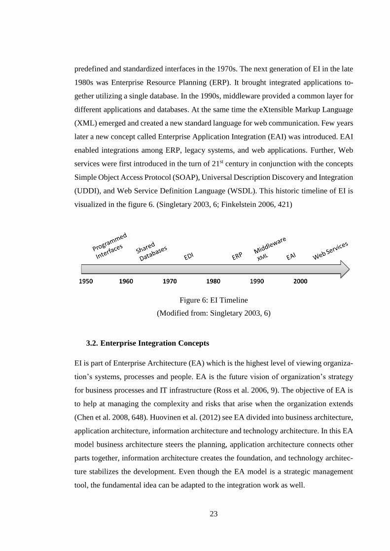
predefined and standardized interfaces in the 1970s. The next generation of EI in the late
1980s was Enterprise Resource Planning (ERP). It brought integrated applications to-
gether utilizing a single database. In the 1990s, middleware provided a common layer for
different applications and databases. At the same time the eXtensible Markup Language
(XML) emerged and created a new standard language for web communication. Few years
later a new concept called Enterprise Application Integration (EAI) was introduced. EAI
enabled integrations among ERP, legacy systems, and web applications. Further, Web
services were first introduced in the turn of 21st century in conjunction with the concepts
Simple Object Access Protocol (SOAP), Universal Description Discovery and Integration
(UDDI), and Web Service Definition Language (WSDL). This historic timeline of EI is
visualized in the figure 6. (Singletary 2003, 6; Finkelstein 2006, 421)
Figure 6: EI Timeline
(Modified from: Singletary 2003, 6)
3.2. Enterprise Integration Concepts
EI is part of Enterprise Architecture (EA) which is the highest level of viewing organiza-
tion’s systems, processes and people. EA is the future vision of organization’s strategy
for business processes and IT infrastructure (Ross et al. 2006, 9). The objective of EA is
to help at managing the complexity and risks that arise when the organization extends
(Chen et al. 2008, 648). Huovinen et al. (2012) see EA divided into business architecture,
application architecture, information architecture and technology architecture. In this EA
model business architecture steers the planning, application architecture connects other
parts together, information architecture creates the foundation, and technology architec-
ture stabilizes the development. Even though the EA model is a strategic management
tool, the fundamental idea can be adapted to the integration work as well.

24
EI can be considered as a technical enabler for business process deployment in organiza-
tions but also as a connector of different applications from diverse locations (Hohpe &
Woolf 2004, 2; Lam & Shankararaman 2004, 40). EI has evolved from technology ori-
ented to business oriented concept. This change has set demands for current EI imple-
mentations and according to Tähtinen (2005), well designed EI is agile and open, since
EI has to support strategic changes made by the business. In addition, EI should be able
to deliver information between different systems, software and people. Cummins (2009)
states, that the key drivers towards agile enterprise are task automation, EAI, the Internet,
Web services and SOA.
Enterprise Application Integration
The term EAI is closely related to EI. The differences are that EAI takes more technical
perspective of viewing things and it is tool-focused. EAI shares data and business pro-
cesses between different applications and data sources (Linthicum 2000, 3). It connects
enterprise’s applications together using middleware which is used as an application-inde-
pendent interface (Ruh et al. 2001, 2).
EAI targets to build up a centralized integration architecture which connects different
integration technologies together. There are three main reasons for the rise of EAI within
organizations. Firstly, E-commerce has pushed organizations to integrate on the business
process level. Secondly, mergers and consolidations of companies have created the need
to integrate different platforms and applications. Thirdly, the popularity of ERP packages
has increased the need for EAI because ERP solutions do not automatically support inte-
gration to other external packaged applications. (Themistocleous 2004, 85; Naveen et al.
2003, 70-71)
Service-oriented Architecture
“SOA is an architectural style whose goal is to achieve loose coupling among in-
teracting software agents. A service is a unit of work done by a service provider to
achieve desired end results for a service consumer.” (He 2003)

25
SOA is a technology architecture model which can be implemented with methods includ-
ing automation, integration, and modeling. It follows the strategic goals of service-orien-
tation and aims to agile and effective enterprise IT. The solution logic in SOA is encap-
sulated into services with accessible APIs. (Erl 2008a, 36-37; Cummins 2009, 27)
Erl (2008b) simplifies SOA design principles into eight key aspects:
- Standardized Service Contract
- Service Loose Coupling
- Service Abstraction
- Service Reusability
- Service Autonomy
- Service Statelessness
- Service Discoverability
- Service Composability
Service contracts have important role in service design. They define the objectives and
the use of service logic. Service contracts can also be viewed as core architectural com-
ponents because other SOA principles have impact on their position, design and utiliza-
tion. A service contract consists of a group of service descriptions: technical and non-
technical ones. The technical one refers to the technical interface and non-technical to
the service description document. (Erl 2008b, 126-127)
Services usually have relationships to other services, surrounding environment, and ser-
vice consumers. This linkage is called as service coupling. The aim of service loose cou-
pling is to design services with minimal dependencies on the underlying environment and
service consumers. In other words, changes in service logic should affect to service con-
sumers as little as possible. (Erl 2008b, 167-168)
Hiding unnecessary details is the responsibility of service abstraction. Basically, this
means that applications should provide only information that is needed by others. Thus,
the provided information can be divided into internal and external information. This al-
lows the internal service logic and information to be changed in the future without mas-
sive modifications into external information structure. (Erl 2008b, 212)

26
Service reusability promotes the reuse of service logic. This means that services should
be designed to be generic. Furthermore, the services should be able to handle different
kind of requests and to support multi-purpose use without changing the service logic. (Erl
2008b, 254-255)
Service autonomy means that services should be able to process their logic independently
without external involvement. This capability increases reliability and predictability be-
cause the control of the service logic is located in one place. (Erl 2008b, 294-295)
Service statelessness refers to the idea where services should be used when needed rather
than continuously. Services should be on passive state when they are not needed and in
active state when they are used. This will make services more scalable as proper state
management services minimizes the use of resources. (Erl 2008b, 326-327)
Service discoverability aims at providing a service registry which collects all services,
their descriptions and other meta information in it. The service registry promotes the ser-
vices that are already implemented in the enterprise and help developers finding reusable
functionalities. Thus, this principle supports the service reusability. (Erl 2008b, 366, 369)
Service composability is a design principle in which the problems are split into smaller
problems and then resolved by smaller service units. This means that smaller services
together compose the core service which coordinates and orchestrates the use of other
services. (Erl 2008b, 389)
3.3. Integration Approach
Lee & Hong (2003) have identified two approaches for EI. The internalization approach
is implemented using ERP which means that organization’s business processes are fitted
into one multi-module application software. The ERP approach integrates data between
organization functions still keeping the data within one software solution. In comparison,
the externalization approach utilizes EAI where existing applications are connected to-
gether using a common interface layer called middleware. The EAI approach targets to

27
improve and automate organization’s overall IT functionality combining plans, methods,
and tools for integration.
Tähtinen (2005) sees internal and external integrations differently. The internal integra-
tion is referred to EAI due to its role to integrate systems within the organization. Busi-
ness-to-Business Integration (B2Bi) is considered as the external integration because
B2Bi occurs when organization communicates with other organizations. This difference
can be justified with different viewpoints. Lee & Hong (2003) observe EI from architec-
ture and business perspective while Tähtinen (2005) uses technical and process perspec-
tives.
According to Hohpe & Woolf (2004), EI approaches can be categorized into six different
types. The categorization is based on the experiences from design and implementation
projects. Figure 7 shows these different approaches.
Figure 7: EI Approaches
(Hohpe & Woolf 2004, 5-9)

28
Information portal gathers information from diverse systems to one location. Information
is aggregated and divided into multiple areas. As a result, interaction between different
information is offered. (Hohpe & Woolf 2004, 6)
Data replication, in its simplest form, provides an access to the same data by copying data
from one place to another. This can be accomplished in different ways. One solution is to
import exported files, while another solution is to transport data in the form of messages.
(Hohpe & Woolf 2004, 6-7)
Shared business function aims to fulfill a task that is assigned to it. The task can vary
from checking the name of the customer to validation of numbers. In this way, a shared
business function reduces redundant functionalities and focuses on reusability. (Hohpe &
Woolf 2004, 7)
Service-oriented architecture consists of a collection of services with interfaces, commu-
nication between services, and service discovery. Each service can be considered as a
function that performs a certain task. The task is defined in the request that service con-
sumer sends. To accomplish its task, the service can also call another service. Therefore,
services are often reusable, but at the same time loosely coupled. Applications need a
centralized list of services to easily find them. This list is also known as service discovery.
(Hohpe & Woolf 2004, 8)
In distributed business process, business transaction is spread to different systems and
business process management (BPM) component controls the progress of the process ex-
ecution. Distributed business process is partly overlapping to SOA. Example of this is a
distributed business process in the form of a SOA. (Hohpe & Woolf, 8-9)
Most of the previously presented integration approaches considered enterprise applica-
tions and services internally. Business-to-business integration extends integration outside
the enterprise since business functions provided by business partners or suppliers need to
be integrated frequently. This sets requirements for transport protocols, security and
standardized data formats. (Hohpe & Woolf 2004, 9)

29
3.4. Integration Architecture
The difference between integration approach and integration architecture is in abstraction.
The integration approach is more of a high level solution and it describes the solution in
a process wise while the integration architecture complements the approach with physical
components and outlines the technical solution.
There are four integration architectures according to Lam & Shankararaman (2007):
- Batch integration
- Point-to-point integration
- Broker-based integration
- Business process integration
In batch integration the focus is on files which are transferred from one location to another
using transport protocols, such as File Transfer Protocol (FTP). The communication is
asynchronous and files are not processed real-time. Due to this batch integration is suita-
ble for high-volume back-end processing. Another architecture model, point-to-point in-
tegration, utilizes interfaces and the communication takes place directly between them.
The downside of this architecture model is high maintenance overhead. In comparison,
the broker-based integration consists of an integration hub which acts as a middleware.
The communication is established using messages which are routed and transformed in
the message broker. This kind of integration architecture supports real time processing
but requires separate tools to be implemented. Last architecture model, business process
integration, is build up upon broker-based integration. In this architecture the integration
follows the workflow which is defined in the business process. The workflow consists of
interactions between IT applications and humans. (Lam & Shankararaman 2007, 12-14)
3.5. Communication Channel
The communication channel is the bridge between communicating systems. Messages
and files are transferred from the sending endpoint to the receiving endpoint through this
channel. If integrations are compared to mail delivery, communication channel is the lo-
gistics service. The mail can be delivered with bicycle, car, train, or airplane. This means

30
that there are multiple ways to deliver the mail but the route has to be specified before-
hand. In the integration context, this means defining the transport protocol whether it is
Hypertext Transfer Protocol Secure (HTTPS) or FTP.
According to Dijkman et al. (2006), a typical communication channel works with follow-
ing scenarios:
- One-to-one message passing
- Synchronous request/response
- Asynchronous request/response with callback
- Asynchronous request/response with polling
- Multicast message passing with publish/subscribe
One-to-one message passing is the simplest message delivery scenario in which the
sender, the party initiating the connection, sends a message to the service provider. In the
synchronous request/response scenario the requestor sends the message and waits until a
response or exception is received. The asynchronous request/response scenarios differ
from this in such a way that the requestor does not wait the response and the response
message is delivered afterwards. There are two ways to handle asynchronous communi-
cation. Either the service provider sends the response back or the requestor polls the ser-
vice provider with certain time interval. In both cases the requestor must provide a mes-
sage id that is used to identify the original message. The last scenario is multicast message
passing with publish/subscribe. In this scenario the requestor sends a notification message
with certain topic to the service provider. This message is then forwarded to subscribers
of this topic. (Dijkman et al. 2006, 332-334)
3.6. Communication Interface
A communication interface, a message endpoint or an adapter, is the point which sepa-
rates the communication channel from the source or target system. It is responsible for
reading and parsing the incoming message into understandable for further use within the
ITSM system.

31
If integrations are compared to mail delivery, the communication interface is the mailbox.
The mailbox is the connection point between the logistics service and the mail recipient.
The mail is delivered to the mail box from where the recipient picks up the mail. In inte-
gration context, the sender application sends the message or file to the receiving endpoint
where it is interpreted for further use.
Spackman & Speaker (2005) have categorized interfaces as follows:
- Database endpoints
- File endpoints
- Application endpoints
- Web endpoints
A database endpoint communicates directly with the database. This means that the end-
point knows the database structure, procedures and triggers. Usually database endpoints
are connectors that enable insert, query, update, and delete operations on database. Java
Database Connectivity (JDBC) and Open Database Connectivity (ODBC) are examples
of database connectors. A file endpoint, on the other hand, communicates directly with
the file system and converts files into information that is then used by the target system.
An application endpoint uses database and file endpoints to communicate with the busi-
ness layer. These kinds of endpoints are invoked by events based on the underlying pro-
cess. Differing from the other endpoints, a web endpoint is connectionless, asynchronous
and usually stateless. This means that the connection is not opened separately and mes-
sages are interpreted independently one by one. Web endpoints can utilize Web services
for different transaction calls or web pages to access information. (Spackman & Speaker
2005, 52, 53, 95, 123, 151)
3.7. Data Transformation
Data is the core part of integrations and without data there is no justification to establish
integration. On the other hand, data itself is just characters or bits that do not mean any-
thing without a specific context. Therefore, data and information should be observed hi-
erarchically as presented in figure 8.

32
Figure 8: Information Levels
(Thierauf 2001, 8; Matinlauri 2011, 30)
The lowest level of information is data which contains unstructured facts, such as char-
acters or pulses. This means that data presents information without any context. On the
next level of the information pyramid data is structured and it existence is transformed
into information. Information gives a context to data by structuring and grouping data.
Knowledge, on the next level, is comprised of structured information and it can be con-
sidered as information about information. Knowledge combines different contexts of in-
formation and compares them with actual experiences of experts. The intelligence level
understands the relationships between the facts highlighted by the lower levels and steers
the decision making towards the objectives. Wisdom, on the other hand, is achieved
through time. It can be gained through experiences, awareness and ability to self-evaluate.
Truth is the top level of the information pyramid and it represents the ultimate fact. (Thier-
auf 2001, 7-11; Tähtinen 2005, 80)
Plain integration refers to data, the lowest level of information. However, when the pro-
cess flow is linked to integration, data is transformed into information. Further, when
people are handling this information, they can add more value from their experiences to
this information. This upgrades information into knowledge. Eventually, when reports
are run on similar information and knowledge, intelligence level can be reached and cor-
relations and relationships can be found.

33
Data transformation is the final part of EI. Once the message is received by the endpoint,
the data transformation will convert the message into form that is understood by the target
system. If source and target systems do not understand information that is exchanged
between the systems, they cannot communicate with each other. Therefore, data transfor-
mation includes adding, removing, changing, and aggregating data. (Spackman &
Speaker 2005, 29-30; Tähtinen 2005, 56)
Data transformation can consist of different layers depending on the transformation need.
These layers are from top to down: Data Structures, Data Types, Data Presentation, and
Transport. The Data Structures layer transforms entities and associations while the Data
Types layer handles field names and values. In turn, the Data Representation layer is used
when there is a need to change the data to a different format, for example from the Ex-
tensible Markup Language (XML) to the Comma Separated Value (CSV). The very bot-
tom layer, the Transport layer, is responsible for transforming the data content between
protocols. (Hohpe & Woolf 2004, 87)
Bertino & Ferrari (2001) have identified three steps for integrating data:
- Data model
- Data schema
- Data instance
A data model is needed to match the information from different data sources to the infor-
mation in the target system. A data schema, on the other hand, is used to unify and confirm
different data structures to one accepted format. This means that the data matches with
the target data but it is presented in a different way. An example of this is the currency
transformation. Lastly, the data instance ensures that the conflicting information is han-
dled properly. (Bertino & Ferrari 2001, 75)
Data integration contains several sub-areas which are not dealt with this context due to
the scope of this thesis. These include data warehousing, data migration, application con-
solidation, operational and real-time Business Intelligence (BI), master data management,
customer data integration and product information management (Sherman 2009, 3).

34
3.8. Technical Interoperability Recommendations
Linthicum (2004) sees that the digital economy and its ecosystem around us are striving
towards automation which makes business more and more dependable on IT. Further-
more, information is expected to be accessible immediately despite the location or device.
To respond to requirements set by the business, organizations’ IT architecture and appli-
cations have to be flexible but at the same support industry guidelines. Therefore, stand-
ards and interoperability recommendations should be utilized when designing and imple-
menting integrations.
The table 2 presents interoperability recommendations which are collected from various
literature sources. The foremost objective of making this list was to identify open stand-
ards and common recommendations without going too deep into technical specifications.
As this thesis focuses on ITSM process integrations, the integration approach can be lim-
ited to B2Bi. Another limitation is that the list covers only standards related to EI and
excludes those that are not. In addition, hardware, software and programming language
recommendations are excluded from this list. The list guides with technical considerations
but sometimes it is not possible to follow these guidelines due to limitations of an ITSM
system.

35
Table 2: Interoperability Recommendations for B2Bi
Recommendation Description Reference
BPM Management approach for
business process orchestra-
tion
Josuttis 2007
OASIS 2012 (WSBPEL)
OMG 2012 (BPMN)
Vernadat 2009
HTTP/HTTPS Transport protocol Vernadat 2009
W3C 2012
Message and Service
Bus
EI pattern Josuttis 2007
Vernadat 2009
REST Architectural style for sys-
tem integration Fielding 2000
Service Registry Metadata repository OASIS 2012 (UDDI)
Vernadat 2009
SOA Architecture design ap-
proach
Josuttis 2007
OASIS 2012 (SOA-RM)
Vernadat 2009
SOAP Network protocol W3C 2012
Web Services Software interface Josuttis 2007
Vernadat 2009
W3C 2012
XML Data presentation language Vernadat 2009
W3C 2012
BPM
BPM is a concept which provides methods and techniques for business process design,
administration, configuration, enactment, and analysis. Handling of business processes
can be accomplished either manually or using software systems which coordinate the or-
chestration of processes. (Weske 2007, 5-6). According to Vernadat (2009), there are two
languages that can be used to model business workflows: the Business Process Modeling
Notation (BPMN) and the Business Process Execution Language (BPEL).

36
HTTP
According to NWG (1999), the Hypertext Transfer Protocol (HTTP) is an application-
level protocol which is used to transfer information across the Internet between infor-
mation systems. The communication takes place using request and response messages.
The basic HTTP methods used in integrations are POST and GET. The difference is that
the POST method contains embedded payload while the GET method contains only the
headers. The secure version of the HTTP is HTTPS which runs over Secure Sockets Layer
(SSL) or Transport Layer Security (TLS) (NWG 2000, 2, 4).
Message and Service Bus
Message-Oriented Middleware (MOM) and Enterprise Service Bus (ESB) are message
queuing solutions which are used to integrate applications asynchronously. Incoming
messages are queued, routed, prioritized and finally delivered to the receiver by the mes-
sage queue. (Vernadat 2009, 1534)
REST
REpresentational State Transfer (REST) is an architectural style for distributed hyperme-
dia systems firstly presented by Fielding (2000). It is based on different network-based
architectural styles and it sets following constraints for the web architecture: client server
style, stateless, cacheable, uniform interface, layered system, and code-on-demand possi-
bility. REST provides an alternative for SOAP by delivering data over HTTP with basic
methods and simpler integration architecture.
Service Registry
Service registry gathers all service descriptions together and promotes these services. Ac-
cording to Vernadat (2009), service registry describes metadata about services. This can
include service name, owner, SLA, and quality information about services. Technically,
service registry should describe the basics needed to access the service. UDDI is an ex-
ample of service registry.

37
SOA
SOA is an approach for designing software architectures which target to flexibility and
loose coupling of services. SOA is comprised of infrastructure, architecture, processes,
and governance. (Josuttis 2007, 12, 18, 19)
SOAP
SOAP means stateless message exchange between sender and receiver. A SOAP message
is wrapped in an XML envelope which consists of header and body parts. The basic usage
scenario is request/response but more complex interaction patterns can be implemented
with the application level logic. SOAP can utilize different protocols for transportation
but usually the binding is to HTTP. (Ericsson & Lafon 2007)
XML
XML is one of the best known open web standards. It has been defined by the World
Wide Web Consortium (W3C) and its text-based format can be used to represent struc-
tured information in a simple way (W3C 2010). Despite its simplicity, XML is a powerful
tool to present information but the downside is the overhead which increases in long ele-
ment names and emphasizes in short messages.
Web Services
Web Services enable machine-to-machine communication via web interfaces which can
be accessed through the network with standard protocols such as HTTP (W3C 2004).
According to Booth et al. (2004), a web service consists of three parts: XML, SOAP, and
WSDL. XML provides flexible and extensible data format which is utilized in a standard
and composable SOAP framework. WSDL describes the web service interfaces. This in-
cludes the bindings to the network protocol and message format as well as the definitions
of abstract messages.

38
4. IT SERVICE MANAGEMENT PROCESS INTEGRATION
Integrations consist of different parts which each have their own purpose and function.
The figure 9 presents a high level picture of an ITSM process integration parts. This figure
helps to understand a basic structure of messaging integration and familiarizes with vo-
cabulary used in an ITSM process integration. For the sake of simplicity, the integration
architecture is selected to be point-to-point approach. Real implementations are complex
systems consisting of different integration layers and components.
Figure 9: ITSM Process Integration Parts
The goal of this chapter is to describe how ITSM processes are integrated and how EI can
be used to support integrations. The chapter combines ITSM theory with practical inte-
gration experiences. Firstly, this chapter illustrates what kind of ITSM process integration
recommendations ITIL provides. Then the chapter demonstrates best practices for design-
ing ITSM process integrations. The chapter continues discussing about implementations
and after this the chapter goes through what actions are needed when the integration is
transitioned to production use. Finally, the chapter presents other considerations that are
involved in ITSM process integrations.

39
4.1. ITIL Recommendation
According to OGC (2007b), one of the key principles of managing ITSM architecture is
to be business aligned not technology driven. ITIL promotes this by naming five different
management areas for ITSM architecture. These areas are presented in figure 10 starting
from business requirements and ending to technology.
Figure 10: ITIL Technology Management Recommendation
(Modified from: OGC 2007b, 41)
At the top of an ITSM architecture is business layer. This layer is responsible for defining
needs, requirements, processes and goals that business sets for the organization. Under-
neath the business layer is the people layer where the scope and role-based tasks are de-
fined. The layer below is the process layer which, in turn, depicts the procedures used in
managing IT services. The next layer, the tools layer, introduces tools used for supporting
and managing the IT infrastructure. The very bottom layer is the technology layer which
consists of IT products and technologies. The purpose of this layer is to support the layers
above and to deliver services both within the organization and beyond its boundaries. The
maximum benefit is gained when the ITSM architecture is integrated end-to-end with
processes and tools. (OGC 2007b, 41)

40
One of the best practices that ITIL brings forth is the mindset where design is carried out
from the top down and implementation from the bottom up (OGC 2007b, 41). In practice,
this means that ITSM management architectures should be designed from business point
of view and implemented from the technology point of view. This will ensure that the
processes and tools are aligned with business but also integrated efficiently with the tech-
nology (OGC 2007b, 41). This same approach can be extended to ITSM process integra-
tions.
4.2. Design
It is important to establish a common language between developers, process people, and
business people when designing ITSM process integration. Achieving this objective
drives towards business alignment. ITIL provides a glossary that can be used in the pro-
cess talk but it lacks a pure technical perspective. This gap can be filled with graphical
presentations about the integration architecture and visualizing system dataflow with a
diagram. Use cases deepen the information in the system dataflow diagram by providing
end-to-end scenarios of the ticket lifecycle. Finally, a data mapping document provides a
simple, understandable way to map data.
Concluded from the previous discussion, the design of an ITSM process integration can
be roughly divided into following phases:
1. Architecture – architecture presentation
2. Process – use cases and system dataflow
3. Data – data mapping
Architecture Presentation
The architecture presentation shows different integration components, communication
channels, stakeholders and technical interfaces. In addition, it also illustrates the funda-
mental integration approach that is used. The architecture presentation gives an overall
insight of interconnected systems.

41
The architecture can be visualized with any drawing tool. In fact, the main point is to
present involved components and their relationships. This helps to support the integration
discussion and to assign responsibilities between different people. Furthermore, the vis-
ualization can be added to the integration design documentation.
Use Cases
Use cases demonstrate scenarios of how an ITSM process can proceed through its phases.
They support the system dataflow diagram by providing additional information of the
ticket lifecycle. Use cases can be graphical or textural and their main objective is to de-
scribe the process flow as comprehensively as possible. It is also important to define the
use cases where the process ends up unexpectedly. This way all scenarios are covered and
the process does not end up uncontrollably.
System Dataflow
The purpose of the system dataflow is to illustrate data exchange between integrated sys-
tems. It hides the technical architecture and presents integrated systems side by side. The
diagram can be built up using common process notations, such as BPMN.
The system dataflow suits especially for transactional integrations in which the message
content is based on the transaction type. The diagram shows when the transactions are
sent and under which conditions. It should especially include status changes since they
are usually the main attributes controlling the process. As a summarization, the diagram
demonstrates the workflow of the ITSM process from start state to end state.
Data Mapping
Data mapping matches the source data to the target data. This can be accomplished using
a data mapping document. Spreadsheets are a powerful tool for this task because different
sheets can present different transactions but other solutions are also applicable. In any
case, the point is to describe source fields, target fields, data lengths, sample values, and
data value mappings.

42
4.3. Implementation
As OGC (2007b) recommends, the ITSM architecture should be implemented from bot-
tom up. In the ITSM process integration context this means that the implementation is
done in the following order.
1. Connectivity
2. Data
3. Process
This order proceeds from application integration to data integration and then to process
integration. If the transitioning process is considered, the implementation is done first in
development or test environment. Then after successful implementation the solution is
placed into production environment.
Connectivity
The connection between ITSM systems is usually implemented first. When the connec-
tion is working then it is easier to add more functionality to the integration. In this ap-
proach, the interface logic is built up iteratively. In comparison to this approach, the whole
process can be implemented before the actual connection. This latter approach requires
very good coordination between the two implementation parties. The risks are bigger
since no end-to-end testing is possible until the implementation is ready.
The implementation of the connection should be started from the communication inter-
faces. They are needed for both inbound and outbound communication but sometimes
only one interface is enough when the integration is one-directional. The inbound com-
munication refers to the communication from the integration partner system. In compar-
ison, the outbound communication takes place towards the integration partner system.
Many ITSM systems provide stub interfaces which can be configured to meet the process
requirements. However, it is possible that no interface exists and the interface has to be
coded manually from scratch. In this case, it is important to define clearly what inputs are
handled and what outputs are produced by the interface.

43
Once the interfaces are ready, the connection should be configured into both ends of the
integration. In practice, this means opening the firewalls, setting up the credentials, and
configuring the endpoints. When all of these steps are successfully accomplished the con-
nection can be tested with a test message. The contents of the test message are irrelevant
because the main point is just to see that data can be sent and received through the inter-
faces.
Data
After implementing the connection, the data is implemented into the integration. This part
can be carried out using message transactions which each represent a different type of a
message.
Message transactions are implemented using the data mapping document which was cre-
ated in the design phase. The goal is to create an object class for each message transaction.
These classes contain attributes that are transaction specific and they act as templates
which can be later utilized easily. Furthermore, an abstract class can be created as a parent
class to present the message framework. Then the child classes inherit its attributes and
the child classes can be customized quickly to meet the requirements.
When incident management is taken as an example, following message transactions are
commonly used:
- OPEN
- UPDATE
- REASSIGN
- RESOLVE
- ACKNOWLEDGE
This list refers to actual process steps but in a technical sense. The point of this list is to
illustrate the commonly used transactions. The full implementation of the incident man-
agement process may require additional transactions depending on the business require-
ments. For example, attachment sending is also a common requirement in ITSM process
integrations.

44
Process
When the connection is working and the message transactions are implemented, the tech-
nical integration and data is combined with the ITSM process. This means that the mes-
sage transactions are linked to the actual process and to the underlying application layer.
All in all, this step transforms the integration into process integration.
The system dataflow diagram is implemented into a working solution in this the process
part. The ITSM process is like a reasoning chain; it is controlled by different events, rules
and conditions which together direct its execution. Related to this, an integration trigger
is a specific condition that links the technical implementation to the process. These trig-
gers start the dataflow process towards the integration partner system. Basically, a trigger
calls an integration functionality which dynamically collects all the needed data into a
message or a file. After that the integration initiates the connection and transports the data
to the integration partner system through the communication channel. An example inte-
gration trigger could be a specific state of a ticket or a support group value.
4.4. Transition to Production
Transition to production means the activities that are needed to move a working solution
from development or test environment to the production environment. If the solution is
implemented in the production environment then the focus of this part is on testing and
deployment.
According to OGC (2007e), ITIL defines seven processes for service transition. All of
these processes are important but the most relevant in the integration context are: transi-
tion planning and support, change management, service validation and testing, and
knowledge management. They are presented next slightly modified for the integration
use.

45
Planning
Transition to production requires careful planning because ITSM systems are business
sensitive systems. Long outages can be expensive and they impact directly to the user
experience. Planning ensures that development efforts are transitioned into production in
a controlled manner.
The objectives of planning consist of planning and coordinating resources, ensuring the
adaptability, and providing straightforward and clear plans (OGC 2007e, 35). Plans
should be documented in a way that different steps can be seen as a roadmap. This helps
to visualize the phases involved and gives an understanding about the needed resources.
Change Management
Integration of an ITSM process changes the ITSM system behavior. This is a change that
needs to be recorded and handled with the organization’s standard process. This process
is known as change management and it is responsible for recording and evaluating
changes (OGC 2007e, 43). Change management is also responsible for verifying that all
the stakeholders are aware of upcoming changes and that all the implemented changes
are controlled. For example, in the integration context it is important that the use of inte-
gration is trained.
Testing
Testing is an important part of every implementation. It reduces the risks in the rollout
and helps to notice bugs before the production use starts. Testing should forward incre-
mentally and proceed from the component level to the data level and then to the process
level. It is important to involve different people in the testing sessions and use the User
Acceptance Test (UAT) to verify and accept the solution for the production use.
Basing test cases to use cases makes the core functionality of the ITSM process covered.
However, in most times this is not enough for comprehensive testing. Therefore, the test
cases should also cover error situations and invalid inputs from the user.

46
Knowledge Management
The knowledge management is responsible for handling the documentation about the in-
tegrations and spreading the knowledge that was gained from the implementation. The
basic idea is to ensure that the integration solution is maintainable even if the key person
leaves from the project or the supporting organization. This means that the solution needs
to be documented so well that the key elements of the core functionality can be understood
from this document.
4.5. Other Considerations
Integrating processes is not just making the data to flow from point A to point B. It in-
volves many other things, such as considering possible worst-case scenarios and impact
of those to processes. Properly made design helps to prepare these kinds of things but no
matter how much time is used in the design phase, there is always a chance that something
goes wrong in the production use. Therefore, integrations need to be logged, monitored
and occurred errors handled with a predefined process. These activities are part of the
support process and should not be forgotten.
Logging
Logging is a simple task of saving information about different activities in the ITSM
system. Logging is extremely useful when something needs to be clarified and without
proper logging it is not possible, or at least difficult, to find out the root cause of the
problem. On the other hand, logging everything is not a good practice either. This will
lead to information overflow increasing data masses. Therefore, a balance in the right
amount of logging should be found and a good practice is to have logging levels. For
example, debug logging can be used in the beginning and after everything is working, the
logging level can be decreased.
It is hard to make a clear distinction of what and when should be logged. From incident
management integration perspective logging should be enabled for sending and receiving

47
messages. The logged information should contain, at the fewest, transaction, identifica-
tion, status, and dialog information. The debug logging, on the other hand, should log
entire messages that makes a complete data level comparison possible. This helps to pin-
point the problem source faster, and helps in the cases where the problem source is un-
known.
Monitoring
Monitoring is the activity of observing the process and dataflow in the ITSM system. It
ensures that everything proceeds like expected and unexpected events are caught. At the
same time it supports error handling by alerting about inconsistencies. Every component
should be monitored in the integration chain. This ensures that problems are noticed, lo-
cated and fixed rapidly. Monitoring can be implemented with listeners, conditions, and
rules.
Error Handling
Errors are inevitable and for this reason they should be prepared to. In ITSM process
integrations the focus of error handling should be on end-to-end and component levels.
This means that process level errors should be handled in the process itself and individual
errors by the components that are currently processing data.
Wrong kind of data, missing data, connection problems, and outages are the common
errors faced in the integrations. Nevertheless, there are different ways to prepare for these.
Incorrect data may be due to incomplete data mapping. Thus, a maintainable field and
data mapping helps implementing rapid mapping changes. Otherwise, data related errors
can be solved with error messages and retransmissions. The connection problems and
outages can be handled with good monitoring, message queuing and acknowledgements.
The key point here is to store the messages for traceability and recovery. In case of an
outage the failed messages can be then resend and no messages are lost. Therefore, the
ITSM system should keep up with the information of which messages are transferred
correctly and which not.

48
Security
Security ensures that confidential data is handled properly and only authorized people can
see the data. Like the error handling, security can be implemented on different levels
depending on the need.
The component level security is implemented within the ITSM system with secure pro-
tocols and restricting the access to external APIs. The data level security, on the other
hand, can be created with message encryption or restricting access to data from certain
users. The process level security is created with well-defined processes which take care
of exception handling. For example, users can be restricted to do unwanted updates.

49
5. FRAMEWORK FOR SERVICE MANAGEMENT INTEGRATION
ITSM process integrations follow a certain process which can be modelled and supported
with the integration framework. The framework divides service management integration
into architecture, process, data, and technology sections. Each section has its own goals
which can be achieved with the framework tools. Besides this, the integration framework
provides a deployment model which steers the integration project from design to transi-
tioning to production.
The framework is intended for designing ITSM process integrations but it also supports
implementation and testing of integrations. As a limitation, the framework is not an all-
inclusive technical guide but it is more of a generic integration framework. In addition,
project management considerations such as schedule, budget and roles are excluded from
the structure. They should be handled separately using project management best practices.
This chapter begins with a description of integration framework development. Then the
chapter continues by presenting the framework structure. After this, the framework tools
and their usage are presented. The last part of this chapter describes the deployment of
the integration framework.
5.1. Framework Development
The development of the integration framework was started by setting initial requirements
which acted as guidelines for finding different theories in literature, especially about
ITSM and EI. The findings from literature review were combined with practical experi-
ences of the researcher and as a result of this combination, an integration framework was
created. The whole development process of the integration framework is presented in the
figure 11.

50
Figure 11: Integration Framework Development Process
Problem Definition and Objectives
The problem to which the integration framework answers is a combination of the two
research questions presented in the first chapter. The first research question searches best
practices for integration between IT organization and integration partner in a process
wise. The second research question explores the characteristics of efficient and maintain-
able integration interfaces with interoperability in mind. Therefore, the foremost objective
of the integration framework is to present a general model for end-to-end integrations
between an IT organization and an integration partner systems in process and technology
wise.
Requirements
The priority one requirement was genericity which was presented in the thesis assign-
ment. This requirement was set to distinct the framework from tool specific instructions.
Business and technology awareness, ease of use, and tool neutrality requirements were
conducted from the need to support day-to-day integration work in integration projects at
Sofigate. Layered structure, modularity, and reusability requirements were conducted
from Erl’s (2008b) SOA design principles which are commonly known best practices for
technical service design. The table 3 summarizes all these requirements and gives a more
detailed description of each requirement.

51
Table 3: Integration Framework Development Requirements
Require-
ment
Description
Business and
technology
awareness
The integration framework should take both business and technology
into consideration.
Ease of use The integration framework should be understandable among different
user groups, such as within developers, architects, business users, and
executives.
Genericity The integration framework should be adaptable to different ITSM inte-
grations.
Layered
structure
The integration framework should prefer abstraction in order to hide
unnecessary details.
Modularity The integration framework should consist of different parts or modules
that could be combined in different ways.
Reusability The integration framework should be reusable in order to be adaptable
into different integration situations.
Tool
neutrality
The integration framework should support different ITSM tools and in-
tegration platforms.
5.2. Framework Structure
The integration framework structure is a four-division between architecture, process,
data, and technology. This core structure of the framework was conducted from ITIL
technology management recommendation (OGC 2007b, 41), The Open Group Architec-
ture Framework (TOGAF) domains (Open Group 2009, 54, 61), and the EA recommen-
dation presented by the ICT Standard (Huovinen et al. 2012, 69). Additionally, practical
experiences from real ITSM process integration designs have supported this structure.

52
The integration framework structure is presented in the figure 12. The figure presents a
best practice approach for ITSM process integration design. The same structure can be
used for implementation and testing but in an opposite order and with minor modifica-
tions. The blue circle in the figure indicates the core framework and the grey rectangles
are extended parts which describe the design objectives of each area.
Figure 12: Integration Framework Structure
(Conducted from: Bertino & Ferrari 2001, 75; Huovinen et al. 2012, 69;
Kruchten 2004, 12; OGC 2007b, 41; Open Group 2009, 54, 61)
The integration framework starts from the upper left corner where architecture initiates
the integration design. Architecture creates an integration strategy which is a cornerstone
for design. It clarifies integrated systems, system roles, integration interfaces and business
requirements (Huovinen et al. 2012, 69). Architecture is also responsible for agreeing
about integration scope, in other words, what is included and excluded in the integration.
It supports process design and aligns business requirements to other sections.

53
Kruchten (2004) suggests that software systems should be modelled from different per-
spectives consisting of state, component, deployment, use-case, scenario and class dia-
grams. Therefore, the process section of the framework starts with defining integration
use cases. The use cases help to understand functional requirements of the integration and
provide details about the integration process. After use cases are defined, transaction
types need to be identified. In this context, they are message types which describe opera-
tions in a process wise. Further, the dataflow diagram, conducted from state and scenario
diagrams, visualizes use cases and transaction types in a process diagram. This diagram
links process design to data design and documents instructions for implementing the pro-
cess logic.
The data section targets to describe how data is received and sent in the integration. There-
fore, this section starts with complementing the transactions, both inbound and outbound,
which were identified in the process section. As a clarification, inbound transactions are
received from external systems while outbound transactions are transferred to the external
system. Bertino & Ferrari (2001) presented data model, data schema and data instance to
describe data integration. These enablers of data integration can be summarized to data
mapping. Simply, this means matching source data to target data but it can contain data
altering or data enrichment steps. Based on previous experiences, ITSM process integra-
tions contain relational data, such as business services, categories, or users, which is scat-
tered over different database tables. This data is then referenced from the original ticket
through a key field. Technically, the integration needs to exchange pre-approved values
between these reference fields. There are two alternatives to handle reference data: one-
to-one mapping or data import. Maintaining one-to-one mapping requires manual work
and thus an automated or semi-automated process for reference data synchronization
should be preferred. This can mean a separate batch integration or a procedure where data
is first exported and then imported manually. One of the systems needs to be the master
or a third system needs to provide the master data since the main objective is to keep the
data synchronized in both sides on a daily basis. These observations and continuous map-
ping problems with the reference data were the reason why the reference data synchroni-
zation concept was placed in the framework.

54
Technology provides capabilities for ITSM process integration making it as the founda-
tion for the framework. Technology supports architecture design with standardized tech-
nologies and protocols (Huovinen et al. 2012, 69). Furthermore, the technology section
provides documentation about integration interfaces and connectivity. Even though the
documentation should be started at the architecture section, the handover takes place after
this section initiating the implementation. Based on past experience, interface specifica-
tions are complex and hard to understand. To address this issue, the integration frame-
work recommends creating a sample file of each transaction type with real data. This will
help an integration partner to start internal testing by simulating the sending party with
the provided data prior establishing end-to-end connectivity.
Implementation Model
If the core structure of the integration framework is observed in a reversed order, an im-
plementation approach can be identified: technology, data, process, and architecture. The
approach follows OGC’s (2007b) philosophy “design top down and implement bottom
up”. Even though this is a very rough division of steps, it illustrates how implementation
should proceed incrementally from technology and connectivity towards architecture and
business. In other words, each step presents a layer which is responsible for specific func-
tionalities. Linthicum (2000) has presented a similar approach for observing data in EAI
context consisting of data, logic and user interface layers. This structure was combined
with the integration framework structure. As a result, an implementation model for ITSM
integration was created. The last layer from the original structure, architecture, was
changed to the user layer due to better suitability to the context. The implementation
model is presented in the figure 13 where different layers, their functionalities, and their
relationships are visualized. The relationships are shown between the layers and the func-
tionalities within the layers.

55
Figure 13: Implementation Model for ITSM Integration
(Conducted from: Linthicum 2000, 24; Open Group 2009, 54, 61)
Generally speaking, business people view things differently than IT people. This puts
pressure on communication between different project members. Implementing ITSM in-
tegration through layers enables seamless communication among developers, process
owners, and project managers as it simplifies the solution and drives the solution towards
SOA approach by separating and hiding implementation components between the layers.
This, in turn, helps to describe the solution structure to the whole project team.
The user layer handles end user’s actions and it operates directly on the user interface.
The process layer focuses on business processes that comprise the business logic. Further,
the data layer is responsible for populating integration messages in a correct data format.
Lastly, the technology layer handles message transfer methods and protocols. When re-
lationships between layers are examined more accurately, it can be seen that user activi-
ties trigger business logic. This leads to execution of business processes and generation
of integration transactions. The data layer populates these transactions and forwards them
as messages to the technology layer, which transfers them to the target destination.
56
The implementation model for ITSM integration should be used as a skeleton for building
up the solution. Thus, the final solution is compiled of different components which pro-
vide the required overall functionality for each layer. The implementation proceeds in
line with the testing making the project approach agile. In practice, this means that com-
ponents are tested with unit tests, data methods with functional tests, a process with end-
to-end tests, and overall solution with user acceptance tests. Therefore, the implementa-
tion preferably starts from the technology layer and ends to the user layer.
Testing Model
Like the implementation model for ITSM integration, the testing model follows the inte-
gration framework in a reversed order: technology, data, process, and architecture. This
approach is not directly applicable for testing but it, in turn, provides a context level struc-
ture for testing recommending testing to be done with bottom-up orientation.
There are four core testing phases: unit testing, integration testing, system testing, and
acceptance testing (Burnstein 2003, 134). These phases acted as a baseline for creating
the testing model. When this baseline was evaluated against the contextual structure of
the integration framework, it was noticed that some phases of the original baseline did
not fill all the testing needs for ITSM integration. Therefore, functional testing replaced
integration testing and end-to-end testing replaced system testing. Basically, the replaced
ones had similar objectives with the ones that replaced them. However, the new ones
described integration testing better in the ITSM context and they were conducted from
the integration framework structure and experiences from ITSM integration projects.
According to Rick & Stefan (2002), modern testing approach proceeds in conjunction
with the implementation. Therefore, testing can be seen as an iterative process where
components and process are tested step by step instead of everything together. This has
been the idea behind the testing model for ITSM integration presented in the figure 14.

57
Figure 14: Testing Model for ITSM Integration
(Conducted from: Burnstein 2003, 134, 164, Rick & Stefan 2002, 11)
Testing begins in the early phases of the implementation with unit testing. The unit tests
focus on testing different components, interfaces and connectivity. Once connectivity is
tested and established, solution logic can be tested with technical use cases. The purpose
of this testing step is to achieve technical readiness for process testing. The end-to-end
process testing ensures that the process is correctly synchronized with the integration and
the integration is aligned with the ITSM process. This testing phase requires input from
process people and cannot be completed only between technical people. The final testing
phase is the user acceptance testing where end users should test the integration from their
perspective. This phase ensures that the integration meets functional requirements and
different user groups can use the integration from their perspective. Additionally, differ-
ent error handling scenarios should be tested in this phase. For example, an end user as-
signs ticket to another integration partner, inputs wrong information to a certain field, or
handles the ticket against the process. The idea behind this is to understand how the sys-
tem works in these unexpected situations.
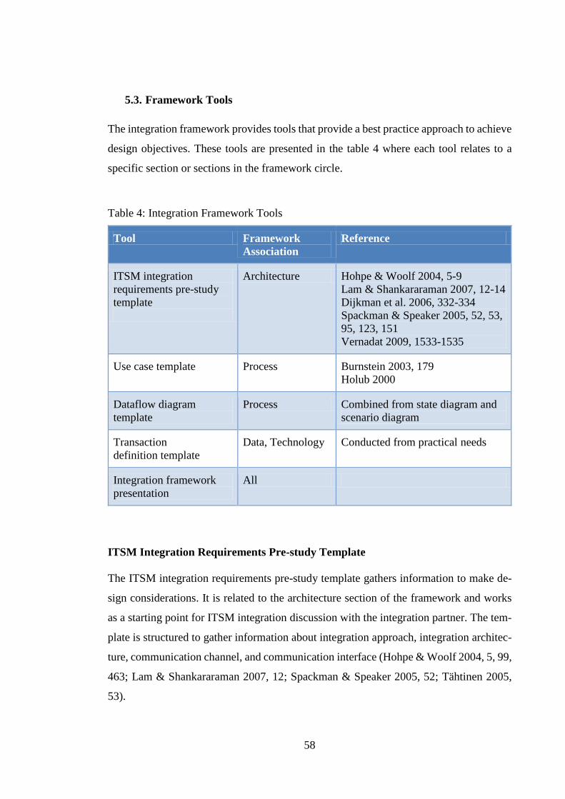
58
5.3. Framework Tools
The integration framework provides tools that provide a best practice approach to achieve
design objectives. These tools are presented in the table 4 where each tool relates to a
specific section or sections in the framework circle.
Table 4: Integration Framework Tools
Tool Framework
Association
Reference
ITSM integration
requirements pre-study
template
Architecture Hohpe & Woolf 2004, 5-9
Lam & Shankararaman 2007, 12-14
Dijkman et al. 2006, 332-334
Spackman & Speaker 2005, 52, 53,
95, 123, 151
Vernadat 2009, 1533-1535
Use case template Process Burnstein 2003, 179
Holub 2000
Dataflow diagram
template
Process Combined from state diagram and
scenario diagram
Transaction
definition template
Data, Technology Conducted from practical needs
Integration framework
presentation
All
ITSM Integration Requirements Pre-study Template
The ITSM integration requirements pre-study template gathers information to make de-
sign considerations. It is related to the architecture section of the framework and works
as a starting point for ITSM integration discussion with the integration partner. The tem-
plate is structured to gather information about integration approach, integration architec-
ture, communication channel, and communication interface (Hohpe & Woolf 2004, 5, 99,
463; Lam & Shankararaman 2007, 12; Spackman & Speaker 2005, 52; Tähtinen 2005,
53).

59
The Appendix A presents ITSM integration requirements pre-study template in use. The
answers in the document are highlighted in yellow and they represent typical ITSM inte-
gration case. Based on these answers, the integration interface would be SOAP web ser-
vice with asynchronous communication model. The communication would be bi-direc-
tional in limited sense meaning that Organization B cannot initiate communication. As
the integration partner has standard interface, the IT organization needs to implement the
web service using integration partner’s static WSDL or alternatively middleware can be
used in between.
Use Case Template
Use cases are commonly used approach to describe functional requirements of the system
but they can be also used to describe system behavior (Burnstein 2003, 179). Since the
use case method describes the process flow from different perspectives, it suits well for
describing the ITSM integration process.
According to Holub (2000), a formal use case consists of name, description, desired out-
come, user goals, participants/roles, dependencies, preconditions, scenarios, workflow,
post conditions, business rules, requirements and implementation notes. These are in-
cluded in the template with certain limitations making the template applicable for ITSM
integration development but also for other system development.
A sample use case for incident management is described in the Appendix B. This use case
is modified from real-life situation where the integration partner is providing support ser-
vices for the IT organization. The use case describes exemplar where Organization A
raises an incident and Organization B resolves it. In this case, Organization A has its own
service desk which provides first and second level support for the own organization. In
turn, Organization B provides third level support for the Organization A meaning that
when Organization A resolvers do not have capabilities to resolve an incident they esca-
late it to Organization B. This use case is text-based and it describes the process from end
user’s perspective.

60
The whole integration process consists of the following use cases:
UC1. Incident is raised by Organization A
UC2. Incident requires more information from Organization A to be resolved
UC3. Incident requires more work from Organization B to be accepted
UC4. Incident is rejected by Organization B resolver
UC5. Incident is resolved by Organization A after it has been exchanged
Dataflow Diagram Template
The dataflow diagram template presents a process diagram which demonstrates integrated
systems and dataflow between them. It gives a quick overview of the integration process
and supports use cases by describing the integration process from system perspective.
This relates the dataflow diagram both to the process and data section of the integration
framework. Modelling a process with the dataflow diagram requires knowledge of pro-
cess notation languages and input from process people.
The dataflow diagram template is constructed as Microsoft Visio file and the template is
prefilled with some process notations to ease the process visualization work. The top row
in the diagram defines the ITSM process name while the row below gives a short descrip-
tion of the main flow of events. On the left hand side, the diagram is split into integration
partner and IT organization sections. These sections separate the responsibility of actions
and they both consist of function and system parts. The function part refers to handlers,
in other words to the human aspect, and the system part to the underlying ITSM system.
The line between integration partner and IT organization sections is important because
arrows crossing this line act as integration transactions. The last swim lane is the subpro-
cess which describes a flow of events that is not part of the main process flow.
The process which was already defined by the use cases is now presented in a form of
system dataflow in the Appendix C. This diagram is exemplar of incident management
process from the system perspective. The diagram visualizes the use case 1, illustrates the
used transactions, and shows associations to other use cases. The process is simple and
does not allow initiation of incidents by Organization B. The dashed arrows demonstrate
automatic message flow meaning that no user action is not needed.

61
The use case 1 consists of the following transactions:
- OPEN by Organization A
- ACK by Organization B
- RESOLVE by Organization B
- CLOSE by Organization A
In order to complete the whole process, the following transactions are required:
- UPDATE by Organization A (UC2)
- REASSIGN by Organization A (UC4)
- REASSIGN by Organization B (UC3)
- RESOLVE by Organization A (UC5)
Transaction Definition Template
The transaction definition template is designed for identifying integration needs at the
data level. The template is used for describing integrated data and message types.
The default template consists of the following sheets:
- Version history
- Transaction overview
- OPEN transaction for both IT organization and Integration partner
- UPDATE transaction for both IT organization and Integration partner
- REASSIGN transaction for both IT organization and Integration partner
- RESOLVE transaction for both IT organization and Integration partner
- ACK transaction for both IT organization and Integration partner
- Value mapping
The transaction definition template is related to the data section of the framework but it
also supports the process section by providing contents for the transactions. The header
of the main sheet tells the transaction name and the initiator of the transaction. In addition
to field mapping, the template provides direct value mapping capabilities. This means
matching field values one-to-one.

62
The template is divided into three parts which illustrate a source system (IT organization
system), a target interface (XML), and a target system (Integration partner system). Even
though the template expects data to be in XML format, the template can be modified to
be used with other file formats as well.
The Appendix D shows an exemplar of how the tool is used. The exemplar presents
OPEN transaction initiated by Organization A. This transaction has been modified from
the real integration mapping and, thus, represent actual fields that are usually transferred
in the incident integration.
Integration Framework Presentation
The integration framework presentation gives an overview of the framework outcome. It
summarizes the framework findings, presents the implementation and testing models, and
goes through the deployment model. It is a quick reference guide for ITSM integrations
and to the integration framework. The presentation goes through goals, principle solution,
implementation steps, best practices, benefits and practical examples.
5.4. Framework Deployment
The integration framework is deployed using ITIL technology management recommen-
dation where design is done top down and implementation bottom up (OGC 2007b, 41).
The deployment order is conducted from the integration framework architecture, the im-
plementation model and the testing model. The figure 15 describes the deployment pro-
cess for the integration framework.

63
Figure 15: Deployment Model of the Integration Framework
The figure is divided into three main phases: design, implementation and testing. Design
tasks can be carried out with the integration framework tools and recommendations. Im-
plementation and testing phases do not have any related tools at this point. However, the
framework provides a suggested order to complete these phases in a controlled manner.
The design phase starts outlining the integration architecture and the business need. This
means clarifying integration components and technical interfaces. Additionally, the ar-
chitecture definition also aligns business requirements to the design phase by presenting
functional requirements for the integration. Thus, this is a good starting point for the in-
tegration project. The integration framework provides a pre-study template for collecting
necessary information to sketch the integration architecture. In addition, the framework
provides technology recommendations that can be used as a basis for making architecture
and technology decisions. The next task towards completing the design is to describe the
integration process flow with the use case template and the dataflow diagram template.
After those are done, data mapping is carried out with the transaction definition template.
The design phase ends with collecting connection endpoint addresses and credentials.

64
Sometimes it is justified to make this last task as early as possible and agree about con-
nectivity, especially when firewall openings tend to take time. This minimizes the idle
time between different tasks in the implementation phase.
The implementation and testing phases proceed concurrently. The implementation phase
starts with configuring the connectivity and firewall openings. This is followed by the
connectivity testing which ensures that connections are open between integrated systems.
The implementation continues creating outbound transactions and inbound data transfor-
mations based on the transaction definition template. These implementation steps are fol-
lowed by the iterative unit testing. This means that each implementation component or
entity is tested individually ensuring that implementation units accept certain inputs and
produce certain outputs. When the unit tests are done, the functional testing takes place.
It can be considered as technical end-to-end testing as it requires input from the integra-
tion partner system. After implementing and testing integration in a technical sense, the
integration should be completed with the ITSM process relations utilizing the defined use
cases and the dataflow diagram. Once the solution is ready, the process is tested with
process end-to-end tests using real scenarios from use cases. The testing ends with the
user acceptance testing which ensures that the process and its components work like ex-
pected. In addition to this it ensures that error handling works like the support governance
model states.
The suggested order for implementation and testing can be overlapping can contain addi-
tional tasks depending on the complexity of the solution. This particular order was chosen
to support the reporting of project progression and to ease the management of integration
implementation.

65
6. ANALYSIS OF INTEGRATION FRAMEWORK
The integration framework presented a generic approach for ITSM integrations. The
framework was composed of the framework visualization, framework tools, and three
models, which were implementation, testing and deployment. To obtain more information
about the maturity of the framework, the framework is analyzed in this chapter.
The chapter starts with evaluating how well the outcome of the integration framework
meets the criteria set at the beginning. After this the chapter discusses about benefits that
the integration framework provides and, finally, the last part of the chapter outlines de-
velopment possibilities.
6.1. Comparison with Initial Requirements
In the very beginning there were seven generic requirements that were guiding the frame-
work development work. These requirements are used as a basis for the analysis by com-
paring the framework to each requirement. If a requirement is not completely met then
reasons for this are discussed and change proposals are addressed.
Business and Technology Aware
Business and technology are domains that should cooperate to achieve common goals.
Still, they often operate on silos making a gap between them. The integration framework
fulfills this gap by taking a layered structure which takes both aspects into consideration.
The structure assumes that the business layer, and more specifically the architecture layer,
provides the need and the technology layer answers to this need by providing capabilities.
The framework presents also a process and a data layer which operate in between archi-
tecture and technology layers providing more detailed view to the integration and nar-
rowing the gap further.
Ease of Use
The integration framework has been designed for different users taking into account de-
velopers, project managers, process owners, and service managers. The framework can

66
also be used as an introduction material for anyone who has interest in integrations. Due
to variety of users, the framework has to provide simple core structure so that anyone
without specific competence can use it.
The key point that makes the framework easy to use is the straightforward deployment
model. It divides the integration project into clear phases and tasks. In addition, the frame-
work uses figures and charts to illustrate complex things, such as processes and dataflow.
In any case, ease of use cannot be evaluated subjectively until the framework has been
widely used among different users and in different cases.
Genericity
Each integration solution is different, at least, when certain level of particularity is
reached. There is no justification to make an integration framework which contains only
specific implementation instructions if the priority one requirement is genericity. These
implementation instructions have their place but they should rather support a generic
framework than work as themselves.
The integration framework can be reused for different ITSM process integrations. This
makes the framework generic. An enabler for this can be found from the abstract and
simple structure of the framework which provides general objectives and tools to design
integrations. In addition, the provided best practices are applicable for any ITSM process,
ITSM tool or implementation technology.
Layered
The integration framework consists of a layered structure which supports information
abstraction. The framework layers are architecture, process, data, and technology which
emerge in the design phase. From the applicable parts this structure is also valid in the
implementation and testing phases. The architecture is replaced with the user layer in the
implementation and testing phases. As the user layer associates closely with user actions
and expectations, it is used for handling user inputs in the implementation phase and do-
ing UAT in the testing phase. Detailed description of design, implementation and testing
phases is presented in the framework deployment model.

67
Modular
A modular structure enables combining different parts together without breaking the
overall structure. This requirement was originally intended for component libraries which
were left off from the framework outcome due to the tool-centricity. The integration
framework can be still seen as modular because it separates the framework structure, the
deployment model, the implementation model, the testing model, and the tools. Each of
these can be used independently without others or alternatively they can be combined
with each other in different orders.
The objective of the modular structure requirement was slightly unclear, especially when
the target was a framework. Thus, it was hard to evaluate the outcome to the requirement
and assess the modularity level. Nevertheless, the framework increases its modularity
level over time when there are more results and sample material to be used creating mass
customized processes. The idea behind this is creating complete building blocks for ITSM
processes which can be then utilized in diverse compositions.
Reusable
Reusing a code snippet, a use case, a template, or even an architecture is highly advisable
as it saves time from reimplementation or from redesign. To be able to reuse, unchanged
parts needs to be identified from the code, process or architecture.
The framework has been designed to unify integration design with the common steps
which can be repeated. Since IT organizations are mostly using same ITSM processes,
the framework can be easily reused when integrating these processes. Furthermore, the
tools provided by the framework are already reused several times in Sofigate Oy.
Tool Neutrality
Since the framework is purposed to be used openly in any organization, the tool neutrality
was an absolute requirement. Due to this, the framework or its tools do not contain any
references to ITSM tool specific information or present ITSM tool dependent principles.
In addition, the framework is generic by nature which supports the tool neutrality.

68
Even though the framework is vendor and ITSM tool neutral, it should be complemented
with specific implementation instructions to maximize the impact and benefits of the use.
These instructions should be stored in a same location with the framework, such as in IT
organization’s knowledge base.
6.2. Benefits
The integration framework brings benefits which can be achieved through the compre-
hensive use of the framework. Even though there are several benefits to be highlighted,
these benefits can be summarized into main ones which illustrate how the framework
helps in the daily ITSM integration work.
Following main benefits can be achieved through the use of the integration framework:
- Common language to use
- Easy and rapid to deploy
- Unified working methods
- Business alignment for integration
- Straightforward process to follow
- Readymade tools for integration design
- Standard outcome documents
- Utilization of industry standards
IT organizations can advance their ITSM integration knowledge with the integration
framework but also use it as a basis for discussion between integration partners. Common
language is the key for successful integration projects as it reduces misunderstandings
and makes work more efficient. The framework helps different user groups perceiving
integration process and provides an easy to understand terminology which extends ITIL.
Additionally, the simple deployment model enables rapid adaptation of the framework.
This is because the framework explains ITSM integrations in a practical way and avoids
focusing on mysterious buzzwords.

69
The impact of the integration framework shows in the everyday work. The framework
unifies working methods and helps ITSM integration projects to start from the right angle.
This, in turn, means that the design starts from the architecture definition making business
requirements comprehensively aligned to the integration. To give an example of practical
usage, the integration framework has been used for planning integration project tasks and
integration workshop agendas within Sofigate Oy.
The integration framework deployment model together with the design objectives provide
straightforward steps that help project managers to understand integration project tasks.
When the projects tasks are clear, it is easier to estimate workloads and budgets but also
to allocate resources. The deployment process is supported by readymade tools which
help to complete ITSM integration design comprehensively. In addition, these tools pro-
duce standardized documents which can be used as implementation specification. These
include a use cases description, a dataflow diagram, and a mapping document.
The technical interoperability recommendations of the integration framework promote
the use of industry standards ensuring technical compatibility in the future. However, this
list of recommendations should be reviewed and updated periodically to meet the criteria
for modern integration.
6.3. Development Areas
The integration framework has one ultimate long-term objective of transforming the
framework into the service management integration framework where business is guiding
process and system integration. This transform can be achieved in small steps with service
management principles. This means identifying and implementing short-term develop-
ment areas one by one.

70
Following short-term future development areas can be identified:
- Build component libraries
- Create mass customized processes
- Complement with practical instructions
- Develop new tools
- Extend the scope from ticketing integrations
- Implement error handling and security aspects
- Implement service level monitoring
Comparing the framework against the initial requirements did not reveal any surprises
since nearly all of the requirements were fulfilled. One exception was modularity, which
did not achieve the wanted level. To address this misalignment, the integration framework
should be complemented with process building blocks which enable mass customized
processes. These building blocks consist of readymade use cases and related component
libraries of code. The mass customized processes and the component libraries would then
reinforce the implementation phase. Originally, the initial sketch of the integration frame-
work contained the component libraries but they were delimited from the core framework
since they were tool-dependent.
The comparison showed that the framework is ITSM tool neutral but it lacked practical
guidelines. Here lies a contradiction since more specific instructions make the integration
framework more tool-dependent while the current form of the framework is too generic.
Additionally, the integration framework provides a baseline for integrations but the
framework focuses mainly on design phase making implementation and testing less cov-
ered. This makes the framework more of a design tool than overall framework. A solution
for this is to develop new tools and add external practical instructions to guide through
the integration. For example, an implementation guide, a reference data synchronization
template, and a test case template are missing from the framework. The implementation
guide would provide detailed technical instructions for implementing different integration
approaches. The reference data synchronization template would support achieving overall
ITSM integration design objectives by clarifying data model differences between inte-
grated ITSM systems. The test case template would give practicality for the testing phase

71
and reinforce the phase with a new tool. However, the implementation guide was ex-
cluded from the framework to keep the framework tool neutral. The two latter tools were
excluded since they were not directly related to the design phase.
The scope of the integration framework was ticket integrations between IT organizations
and external integration partners. Even though this scope covers the most common ITSM
integrations within IT organizations, there is a need to extend the scope broader and sup-
port diverse ITSM integrations, such as batch integration. Since all integration designs
follow the same pattern as presented in the framework architecture, the core part of the
integration framework is usable for any integration design already. In order to do this, the
design objectives need to be updated to support other integrations as well. In practice, this
means that there would be alternative deployment models for different integrations which
would be then supported by new tools. For example, event-based integrations and batch
integrations could have different integration approach which is determined in the archi-
tecture definition.
According to van Bon et al. (2008), availability, capacity, performance, security, confi-
dentiality, scalability, adjustability, and portability are attributes that measure service
quality. These attributes also reflect to the quality of integrations and further to the struc-
ture of the integration framework. It is not reasonable to compare the integration frame-
work outcome against them as they require operational level metrics for measurement. In
turn, the integration framework should focus on improving these aspects and providing
best practices that lead measuring them. As a conclusion, error handling and security fea-
tures should be added into the framework. This will indirectly enhance all of the attrib-
utes, especially availability, security and confidentiality. In addition, monitoring of ser-
vice levels should be taken part of the framework to enable the measurement of quality
in ITSM integrations. In practice, this means monitoring integration errors, downtimes
and agreed service levels. Modern integration platforms provide Business Activity Mon-
itoring (BAM) functionalities which support this need.

72
7. CONCLUSIONS
The main objective of this thesis was to create an applicable integration framework to
help with ITSM integrations. For observing the objective, two different perspectives were
assigned: process and technology. They associated with the actual research questions pre-
sented next:
1. What are the best practices for integrating an ITSM process with an integration part-
ner?
2. How integration interfaces should be built to support the interoperability and the
ease at maintenance?
In the regard of the practical need, the action research approach was chosen to explore
the research questions. This approach shaped the research process into the following
form: theory, framework, implementation and analysis. In the theory part different liter-
ature sources were reviewed. Then the findings from theory were combined with re-
searcher’s practical experiences and were transformed into the ITSM integration frame-
work. Further, the framework was used in ITSM integration implementation and, finally,
the outcome of the framework was analyzed and evaluated.
The main results of this thesis were:
- Framework architecture
- Framework tools
- Implementation model
- Testing model
- Deployment model
This chapter evaluates the results that were presented in this thesis. The evaluation assess
how well the research questions were answered and objectives were achieved. Then after
evaluation, the chapter discusses about exploitation possibilities of the results. Finally,
the last part of the chapter visions future potentiality of the framework.

73
7.1. Evaluation of Results
The newly created integration framework provided answers to the research questions but
the second research question was not answered thoroughly. This was because the initially
chosen perspective for ITSM integration framework seemed to increase ITSM tool de-
pendency and technology itself. Therefore, the main focus of the thesis was shifted more
over the first research question. This focus change altered the perspective of the thesis
into a combination of project management and process oriented principles. Despite this,
the second research question was not totally forgotten since it was answered on an archi-
tectural level.
The integration framework answers directly to the first research question since the frame-
work provides ITSM integration best practices for project management, design, imple-
mentation and testing. As a fundamental best practice, the framework contained a four-
division structure of architecture, process, data, and technology. This acted as a baseline
for design, implementation and testing. The structure has its roots in the EA model
(Huovinen et al. 2012, 69), ITIL technology management recommendation (OGC 2007b,
41) and TOGAF domains (Open Group 2009, 54, 61). Even though the structure is very
simple, it summarizes the integration phases comprehensively at high level. Even people
with zero knowledge of ITSM integrations can understand the overall process and phases
included. Furthermore, the used literature references demonstrate that integrations should
be seen as a part of the EA and not as separate interfaces. Another observation is that the
service management principles presented by ITIL and other frameworks are applicable
for integrations as well. This underlines the statement that integrations should be seen as
services.
Currently the framework includes following tools:
- ITSM integration requirements pre-study template
- Use case template
- Dataflow diagram template
- Transaction definition template
- Integration framework presentation

74
These tools help to achieve the design objectives set by each section of the framework.
Based on experiences, it is common that integration specifications are badly structured,
complex and out-of-date. This makes specifications hard to understand and the integration
partner ends up consuming valuable calendar time while struggling with the implemen-
tation details. This misalignment makes the integration work technology-oriented instead
of business- and process-oriented. The framework tools address this problem with stand-
ard outcome documents. Therefore, the framework tools can be considered as best prac-
tices for ITSM integration design meaning that they are also part of the answer to the first
research question.
The integration work requires process understanding but at the same time technical skills
to perceive limitations of the technology. These skills are needed when the implementa-
tion and testing models are utilized. They present the practical side of best practices along
with the deployment model. In fact, the implementation model and the technology in-
teroperability recommendations are only parts of the thesis which answer to the second
research question.
The implementation model recommends that the interface and the integration process
should be implemented using SOA approach. This means that the code components are
done in a reusable manner and with abstraction levels. Taking this approach makes the
components generic enabling their reuse in different cases. This, on the other hand, saves
implementation time. The implementation of abstraction layers means separating tech-
nology, data, process, and user interface levels. Because of this, the interface remains
maintainable as fixes can be applied to certain level without breaking the overall solution.
Furthermore, the technology interoperability recommendations presented in the table 2
illustrated what technologies should be preferred in order to maintain interoperability.
The generic trend was to utilize Internet protocols and methods for communication. Fi-
nally, the last aspect to the second research question was data transformation presented
by Spackman & Speaker (2005). This important part of the interface design is the part
which is subjected to continuous changes because data mappings tend to change. There-
fore, the data mapping should be maintained somewhere else than in the code. For exam-
ple, a mapping table is a good place for this.

75
7.2. Exploitation of Results
The integration framework adapts to different integration needs. Therefore, the results of
the thesis can be used differently in five different scenarios. The basic scenario is to use
the framework as a project management tool for planning integration project phases and
tasks. This is because the framework gives an overview of the complete integration pro-
ject and illustrates what is required in each phase. The second scenario is to use the inte-
gration framework as an architecture tool for modelling SOA based solutions. The frame-
work architecture is conducted from the Open Group’s (2009) EA best practice model
and OGC’s (2007b) technology management recommendation using Erl’s (2008b) SOA
design principles. This makes the framework architecture also adaptable for building in-
tegration architectures. The third scenario is to use the integration framework as a refer-
ence integration design tool. This can be justified with the straightforward process and
tools that the framework provides. The process tools, such as the use case template and
the dataflow diagram template, are conducted from the process best practices by Burn-
stein (2003) and Holub (2000), ensuring that the design is carried out comprehensively.
The fourth scenario is to use the framework as an implementation guide and a reference
solution. The implementation model supports this by taking into consideration different
layers of implementation which structurize the work into clear blocks. The model is based
on Linthicum’s (2000) and Open Group’s (2009) best practice architecture. The last sce-
nario is to use the framework as a testing tool. This is supported by the testing model
which suggests a preferred approach for testing. This approach is conducted from the
software testing best practices presented by Burnstein (2003) and Rick & Stefan (2002).
If the previous discussion is presented through roles, there would be five different ones
using the integration framework. These are a project manager, an architect, a process de-
signer, a developer, and a tester. Of course, the integration framework is also usable for
executives due to its abstraction. This means that the framework can be used to visualize
where the integration project is going and justifying different integration related consid-
erations to the management.

76
As a conclusion, the integration framework is usable for any ITSM integration through
different organizations but the adaptation level depends on the need and role. Further, the
framework can be used as an informative tool to spread knowledge about ITSM integra-
tion best practices.
7.3. Future
Cummins (2009) described that the key drivers towards agile enterprise are task automa-
tion, EAI, the Internet, Web services and SOA. While the world is becoming more ser-
vice-oriented, the need for service integration is increasing. This is also the case with the
ITSM since IT service automation is becoming more popular. The generic integration
framework answers to this need but, nevertheless, there are no shortcuts for ITSM inte-
grations. Each integration requires careful planning, robust design, and quality in imple-
mentation. At least to this day, these phases could not have been automated.
While technology and business processes involve, the integration framework needs to
keep up with the development as well. According to OGC (2007a), CSI aligns IT services
to the changing business needs by reviewing and analyzing improvement opportunities.
This best practice and ideology should be fostered in the integration framework as well.
Even though the core structure of the framework is intended to remain unchanged, the
design objectives and framework tools should be reviewed periodically to meet the future
needs of ITSM integration. This will drive the framework towards its long-term objective
of transforming it into the service management integration framework.
IT organizations would have easier ITSM integrations if every organization was using
same kind of data. In practice, this is very challenging since each organization has its own
distinctive processes which produce heterogeneous data. Despite this, there are similari-
ties on the contextual level meaning that different organizations have named the same
data differently. This raises an important question: how to create a common, universally
accepted, data model between ITSM integration partners? One solution would be to agree
about the core data and fields with extension possibility. However, the reason why this
has not been succeeded, is the difficulty of engagement between IT organizations, ven-
dors, suppliers and partners.

77
When thinking future trends, it is obvious that cloud services will strengthen their role in
the ITSM landscape and within the whole IT sector. This can be seen through the rise of
services that are provided over the Internet to private users and companies. For example,
Amazon and Twitter provide these kind of services. Combining cloud services with or-
ganization’s internal hosted systems requires new ways of thinking. Thus, an important
question can be raised: how to enable the flexibility and service orientation among organ-
ization’s scattered and partly hybrid resources? Even though the solution models for this
question rely on the EA and SOA concepts, the dilemma is in architectural choices that
need to support the enterprise agility now and in the future.

78
REFERENCES
Bertino, E., Ferrari, E. 2001. XML and data integration. Internet Computing, IEEE. Vol.
5, no. 6, pp. 75-76. ISSN 1089-7801
Booth, D., Haas, H., McCabe, F., Newcomer, E., Champion, M., Ferris, C., Orchard, D.
2004. Web services architecture. W3C Working Group Note 11. [www document] [re-
trieved 1st Oct, 2012] From: http://www.w3.org/TR/ws-arch/
Burnstein, Ilene 2003. Practical software testing – a process-oriented approach. New
York (NY): Springer. 709 p. ISBN 0-387-95131-8
Chen D., Doumeingts, G., Vernadat, F. 2008. Architectures for enterprise integration
and interoperability - past, present and future. Communications of the ACM. Vol. 59,
no. 7, pp. 647-659. ISSN 0166-3615
Chesbrough, H., Spohrer, J. 2006. A research manifesto for services science. Communi-
cations of the ACM. Vol. 49, no. 7, pp. 35-40. ISSN 0001-0782
Clifford, David 2008. Implementing ISO/IEC 20000 certification - the roadmap. Zalt-
bommel: Van Haren Publishing. 198 p. ISBN 978-90-8753-082-2
Crowther, D., Lancaster, G. 2012. Research Methods. Oxford: Butterworth-Heinemann.
2nd edition. 304 p. ISBN 978-0-7506-8953-3
Cummins, Fred 2009. Building the agile enterprise with SOA, BPM and MBM [e-
book]. Morgan Kaufmann. 306 p. ISBN 978-0-12-374445-6
Dijkman, R., Dirgahayu, T., Quartel, D. 2006. Towards advanced interaction concepts.
Enterprise Distributed Object Computing Conference (EDOC ’06). Proceedings of the
10th IEEE International. pp. 331-344.
Ericsson, N., Lafon, Y. 2007. SOAP version 1.2 part 0 – primer. W3C Recommenda-
tion. [www document] [retrieved 26th Oct, 2012] From:
http://www.w3.org/TR/2007/REC-soap12-part0-20070427/
Erl, Thomas 2008a. SOA design patterns. Upper Saddle River (NJ): Prentice Hall PTR.
814 p. ISBN 978-0-13-613516-6
Erl, Thomas 2008b. SOA – principles of service design. Upper Saddle River (NJ): Pren-
tice Hall PTR. 573 p. ISBN 978-0-13-234482-1
Finkelstein, Clive 2006. Enterprise architecture for integration – rapid delivery methods
and technologies. Norwood (MA): Artech House. 500 p. ISBN 1-58053-713-8
Galup, S., Dattero, R., Quan, J., Conger, S. 2009. An overview of IT service manage-
ment. Communications of the ACM. Vol. 52, no. 5, pp. 124-127. ISSN 0001-0782

79
Deutscher, J.-H., Felden, C. 2010. Concept for implementation of cost effective infor-
mation technology service management (ITSM) in organizations. Network Operations
and Management Symposium Workshops (NOMS Wksps). Proceedings of the 2010
IEEE/IFIP. pp. 167-168. ISBN 978-1-4244-6037-3
Fielding, Roy 2000. Architectural styles and the design of network-based software ar-
chitectures. [e-document]. A Dissertation. University of California. The department of
Information and Computer Science. [retrieved 26th Oct, 2012] From:
http://www.ics.uci.edu/~fielding/pubs/dissertation/fielding_dissertation.pdf
He, Hao 2003. What is service-oriented architecture. [www-document] [retrieved 16th
Sep, 2012] From: http://www.xml.com/pub/a/ws/2003/09/30/soa.html
Holub, Allen 2000. OO design process – Use cases, an introduction. [www-document].
IBM developerWorks. [retrieved 19th Aug, 2013] From: http://www.ibm.com/devel-
operworks/library/co-design5/index.html
Huovinen, J., Kanto, T., Myyry, P., Malinen, T. 2012. ICT Standard – v 2.0. Espoo: ICT
Standard Forum. 159 p. ISBN 978-952-67383-2-1 [retrieved 1st Dec, 2012] From:
https://www.ictstandard.org/files/ict2/digipaper_ict/index.html
Hohpe, G., Woolf, B. 2004. Enterprise integration patterns – designing, building, and
deploying messaging solutions. Boston (MA): Addison-Wesley. 683 p. ISBN 0-321-
20068-3
ISO/FDIS 19439. 2005. Enterprise integration – Framework for enterprise modeling [e-
document]. Final Draft. ISO/TC 184/SC 5. 34 p. [retrieved 19th Aug, 2012] From:
http://workspaces.nema.org/public/ustag_iso_tc184_sc5/Shared%20Docu-
ments/TAG%20Bal-
lots/US%20280%20%20ISO%20FDIS%2019439/ISO_FDIS_19439__E_.pdf
Josuttis, Nicolai 2007. SOA in practice – the art of distributed system design. Sebasto-
pol (CA): O’Reilly Media. 342 p. ISBN 978-0-596-52955-0
Kruchten, Philippe 2004. The Rational Unified Process – an introduction (3rd edition).
Addison-Wesley. 310 p. ISBN 978-0-32119-770-2
Lam, W.-H., Shankararaman, V. 2004. An enterprise integration methodology. IT Pro-
fessional. Vol. 6, no. 2, pp. 40-48. ISSN 1520-9202
Lam, W.-H., Shankararaman, V. 2007. Enterprise architecture and integration: methods,
implementation, and integration. Hershey (PA). London: Idea Group Inc (IGI). 344 p.
ISBN 978-1-59140-887-1
Lee, J., Siau, K., Hong, S. 2003. Enterprise integration with ERP and EAI. Communica-
tions of the ACM. Vol. 46, no. 2, pp. 54-60. ISSN 0001-0782

80
Linthicum, David 2000. Enterprise Application Integration. Essex (UK): Addison-Wes-
ley Professional. 377 p. ISBN 0-201-61583-5
Linthicum, David 2004. Next generation application integration - from simple infor-
mation to Web services. Boston: Addison-Wesley Professional. 488 p. ISBN 0-201-
84456-7
Matinlauri, Arttu-Matti 2011. Rautatieliikennedatan jalostaminen päätöksenteontueksi
kehittyneen data-analytiikan menetelmin. Master Thesis. Tampere: Tampere University
of Technology. 109 p.
Naveen, E., Yen, D.-C., Rajkumar, T.-M. 2003. Enterprise application integration in the
electronic commerce world. Computer Standard Interfaces. Vol. 25, no. 2, pp. 69-82.
ISSN 0920-5489
Network Working Group (NWG) 1999. RFC 2616 – Hypertext transfer protocol
HTTP/1.1. The Internet Society. 175 p. [www document] [retrieved 1st Oct, 2012]
From: http://www.ietf.org/rfc/rfc2616.txt
Network Working Group (NWG) 2000. RFC 2818 – HTTP over TLS. The Internet So-
ciety. 7 p. [www document] [retrieved 1st Oct, 2012] From:
http://www.ietf.org/rfc/rfc2818.txt
OASIS, Organization for the Advancement of Structured Information Standards 2012.
Standards. [www document] [retrieved 4th Oct, 2012] From: https://www.oasis-
open.org/standards
OGC, Office of Government Commerce 2007a. Continual service improvement. Lon-
don: TSO. 221 p. ISBN 978-0-11-331049-4
OGC, Office of Government Commerce 2007b. Service design. London: TSO. 334 p.
ISBN 978-0-11-331047-0
OGC, Office of Government Commerce 2007c. Service operation. London: TSO. 263 p.
ISBN 978-0-11-331046-0
OGC, Office of Government Commerce 2007d. The official introduction to the ITIL
service lifecycle. London: TSO. 238 p. ISBN 978-0-11-331061-6
OGC, Office of Government Commerce 2007e. Service transition. London: TSO. 262 p.
ISBN 978-0-11-331048-7
OMG, Object Management Group 2012. Specifications. [www document] [retrieved 4th
Oct, 2012] From: http://www.omg.org/spec/
Open Group 2009. TOGAF Version 9 – The Open Group Architecture Framework (TO-
GAF). The Open Group. 744 p. ISBN 978-90-8753-230-7, G091

81
Rick, D., Stefan, P. 2002. Systematic software testing. Artech House. 536 p. ISBN 1-
58053-508-9
Ruh, W.-A., Maginnis, F.-X., Brown, J.-B., 2001. Enterprise application integration - A
Wiley tech brief. New York (NY): John Wiley. 211 p. ISBN 978-0471376418
Ross, J., Weill, P., Robertson, D., 2006. Enterprise architecture as strategy. Boston:
Harvard Business Press. 234 p. ISBN 1-59139-839-8
Sherman, Rick 2009. Beyond ETL & data warehousing. Information Management. Sup-
plement: Feb 19th. ISSN 1521-2912
Singletary, Lester 2003. Empirical study of attributes and perceived benefits of applica-
tions integration for enterprise systems [e-document]. A Dissertation. Louisiana State
University. The Interdepartmental Program in Business Administration.[retrieved 13th
Aug, 2012] From: http://etd.lsu.edu/docs/available/etd-0618103-160439/unre-
stricted/Singletary_dis.pdf
Spackman, D., Speaker, M. 2005. Enterprise integration solution. Redmond: Microsoft
Press. 348 p. ISBN 0-7356-2060-1
Sofigate 2013. Company info. [www document] [retrieved 5th Oct, 2013]. From:
http://sofigate.com/en/company-info
Themistocleous, Marinos. 2004. Justifying the decisions for EAI implementations - a
validated proposition of influential factors. Journal of Enterprise Information Manage-
ment. Vol. 17, no. 2, pp. 85-104. ISSN 1741-0398
Thierauf, Robert 2001. Effective business intelligence systems. Westport (CO): Quorum
Books. 370 p. ISBN 1-56720-370-1
Tähtinen, Sami 2005. Järjestelmäintegraatio – tarve, vaihtoehdot, toteutus. Jyväskylä:
Talentum. 217 p. ISBN 952-14-0854-5
Van Bon, J., de Jong, A., Kolthof, A., Pieper, M., Tjassing, R., van der Veen, A., Ver-
heijen, T. 2007a. Foundations of IT service management based on ITIL V3. Zaltbom-
mel: Van Haren Publishing. 360 p. ISBN: 978-90-8753-057-0
Van Bon, J., de Jong, A., Kolthof, A., Pieper, M., Rozemeijer, E., Tjassing, R., van der
Veen, A., Verheijen, T. 2007b. IT service management: an introduction. Zaltbommel:
Van Haren Publishing. 514 p. ISBN: 978-90-8753-051-8
Van Bon, J., Polter, S., Verheijen, T., van Selm, L. 2008. ISO/IEC 20000 - an introduc-
tion. Zaltbommel: Van Haren Publishing. 226 p. ISBN: 978-90-8753-081-5
Vernadat, François 2009. Enterprise integration and interoperability. Springer Hand-
book of Automation. pp. 1529-1538. ISBN 978-3-540-78831-7

82
Weske, Mathias 2007. Business process management – concepts, languages, architec-
tures. Springer. 368 p. ISBN 978-3-540-73521-2
W3C 2004. Web services glossary. [www document] [retrieved 1st Oct, 2012] From:
http://www.w3.org/TR/ws-gloss/
W3C 2010. XML essentials. [www document] [retrieved 30th Sep, 2012] From:
http://www.w3.org/standards/xml/core
W3C 2012. All standards and drafts. [www document] [retrieved 2nd Oct, 2012] From:
http://www.w3.org/TR/
Zhang, S., Wang, P., Ding, Z., Zong, Y. 2009. Organization ITIL process integration
based on Web services. World Congress in Software Engineering (WCSE ‘09). pp. 167-
168. ISBN 978-0-7695-3570-8

APPENDICES
APPENDIX A: Exemplar of ITSM Integration Requirements Pre-Study Template
APPENDIX B: Exemplar of Use Case Template
APPENDIX C: Exemplar of Dataflow Diagram Template
APPENDIX D: Exemplar of Transaction Definition Template

APPENDIX A
ITSM Integration Requirements Pre-study
This document is designed to be used to gather ITSM integration requirements for making
design considerations about the integration approach, architecture and technology. The
results of this pre-study require analysis by a person who has sufficient technical skills
and ability to understand the process flow.
Company: Organization A
Company ITSM system: System X
Integration partner: Organization B
Integration partner system: System Y
Business need: To automate incident management process between integration partner
and to enable reporting on incidents
Highlight the choices which describe the situation best.
1. What ITSM processes are integrated?
a) Incident Management
b) Request Fulfillment
c) Change Management
d) Problem Management
e) Access Management
f) Service Asset and Configuration Management
g) Service Catalogue Management
h) Event Management
i) Other? What?
2. What are expected volumes of transferred data (messages/files) approximately?
a) Dozens per day or less
b) Hundreds per day
c) Thousands per day
d) Several thousands (10000 >) per day or more
3. Does the integration partner use middleware to integrate systems?
a) Message Broker
b) ESB
c) Other Middleware? What?
d) No middleware is used

4. In which direction data moves between company and integration partner?
a) One-way outbound: From company to integration partner
b) One-way inbound: From integration partner towards company
c) Two-way full: Data moves similarly in both directions in technical and process wise
d) Two-way with restrictions: Data moves technically in both directions but there are
limitations in process wise, for example, integration partner is not allowed to initi-
ate the communication
5. How data should be exchanged (integration style)?
a) Transactional data exchange – One record per transaction or file exchanged nearly
real-time
b) Batch job – Larger file containing multiple records run on a scheduled basis
c) Event trigger – Interface starts the execution of predefined actions from the sent
message
6. Are attachments exchanged in the integration?
a) Yes
b) No
7. What endpoints does the integration partner system provide?
a) Database endpoints
b) File endpoints
c) Application endpoints
d) Web endpoints
8. How the integration partner’s system interface operates (PUSH vs. PULL)?
a) Active (PUSH) – Interface is able to initiate communication
b) Passive (PULL) – Interface is NOT able to initiate communication
9. What communication models are available?
a) One-to-one message passing
b) Synchronous request/response
c) Asynchronous request/response with callback
d) Asynchronous request/response with polling
e) Multicast message passing with publish/subscribe
10. What technology is supported by the integration partner interface?
a) SOAP Web Service
b) REST Web Service
c) HTTP, HTTPS
d) FTP, SFTP
e) JDBC
f) ODBC
g) LDAP
h) Email
i) Other? What?

11. What is the flexibility level of integration partner’s interface?
a) Standard interface – No modifications allowed, except mappings
b) Mass customized interface – Some modifications are possible but core functions
are standard
c) Custom interface – Nearly all modifications are possible

APPENDIX B
UC1: End user from the Organization A raises an incident Description Incident is created in the System X by the resolver from Organization A. The
system X transfers the case into the system Y for resolving. The resolver from Organization B starts to work with incident and resolves it. The resolution is transferred back to the system X by the system Y. After this the resolver A ac-cepts the resolution and closes the incident.
Business Event Organization A needs organization B to resolve an incident
Actor(s) - Organization A end user - Organization A resolver - Organization B resolver - System X - System Y
Precondition(s) - System X and System Y are operational - Communication is working between the systems
Outcome (Success) Incident is resolved by Organization B resolver
Outcome (Failed) Incident is rejected/cancelled by Organization B resolver
Associations UC2: Incident requires more information from Organization A to be resolved UC3: Incident requires more work from Organization B to be accepted UC4: Incident is rejected by Organization B resolver UC5: Incident is resolved by Organization A after it has been exchanged
Workflow MAIN: 1. End user from the Organization A has faced an issue and he/she
raises an incident via email, phone, or company portal. 2. The incident is created in System X. 3. The resolver A starts to work with the incident and notices that the
incident requires special knowledge from Organization B. Therefore, the resolver A assigns the incident to the Organization B group.
4. The integration is triggered and the system X transfers the incident to the system Y.
5. The system Y automatically responses to this request with the newly created incident id. This id is then updated on the originally created incident in the system X.
6. Resolver B validates the new incident. 7. Resolver B resolves the incident and writes details about resolution in
the incident. 8. The system Y transfers the updated resolution to the system Y. 9. The resolver A validates the resolution and closes the incident. 10. The closure information is updated to the system Y.
ALTERNATIVE:
A. Step 6: Incident is rejected by resolver B. Then UC4 is applicable. B. Step 7: Incident cannot be resolved with current information. There-
fore, more information is required from Organization A. Then UC 2 is applicable.
C. Step 9: Incident is not accepted by resolver A. Then updated infor-mation is sent back to resolver B through the integration and UC4 is applicable.
Notes This use case describes the process mainly from the process view. For more detailed technical flow see the dataflow diagram and the related transactions.

APPENDIX C

APPENDIX D