a follow-up cg runtime tutorial for readers of the cg...
TRANSCRIPT

1
Re-implementing the Follow-up Cg Runtime Tutorial with CgFX*
Mark J. Kilgard NVIDIA Corporation
Austin, Texas
April 23, 2006
The source code discussed in this tutorial is installed by the Cg Toolkit installer for Windows at c:\Program Files\NVIDIA Corporation\Cg\examples\OpenGL\advanced\cgfx_bumpdemo
This whitepaper continues a tutorial I wrote a year ago titled “A Follow-up Cg Runtime Tutorial for Readers of The Cg Tutorial” in which I presented a complete OpenGL demo written in ANSI C that renders a procedurally-generated bump-mapped torus using Cg programs discussed in The Cg Tutorial,† a book I co-wrote about Cg programming.
Now I present the same demo but re-implement it with CgFX, a shading effect system built around Cg. CgFX is a file format and an associated runtime API for describing a complete shading effect that includes Cg programs, how these Cg programs are combined into potentially multiple rendering passes, how the input parameters for these programs are computed, how other non-programmable GPU state should be configured, and finally annotations so an application can appropriately associate its application-state to the effect’s input parameters and rendering passes.
CgFX allows us to package a complete shading effect as a single unit so it can be more easily tweaked and shared among multiple applications. Re-implementing the original demo in CgFX also results in less application code.
The original whitepaper’s demo program is called cg_bumpdemo so the new CgFX-based demo is called cgfx_bumpdemo. Before walking you through the complete source code for cgfx_bumpdemo, I first explain the rationale for CgFX and how CgFX structures the specification of a shading effect.
* You have permission to redistribute or make digital or hard copy of this article for non-commercial or educational use.
† The Cg Tutorial by Randima (Randy) Fernando and Mark J. Kilgard is published by Addison-Wesley (ISBN 0321194969, 336 pages). The book is now available in Japanese translation (ISBN4-939007-55-3).
2
1. The Why and What of CgFX
CgFX addresses the fact that Cg programs, even though written in an expressive high-level language, do not completely express what is required to use a particular Cg program properly for a given shading effect. For one thing, you often need both a vertex and fragment program to be used simultaneously. You also need to know how non-programmable state such as blending or depth testing should be configured. The complete effect may even require multiple rendering passes, performed in a particular order. And because of the differences in graphics hardware you must support or varying requirements for rendering quality and performance, multiple implementations of a particular effect—termed techniques in CgFX—may be required. Finally the parameters of the effect may require meta-information about the parameters such as their valid range or how the parameter is computed from other parameters. The big advantage of CgFX is you combine everything needed to render a shading effect in a single place.
If you simply use Cg programs to implement a given rendering effect, you wind up embedding “application/effect glue” knowledge about your rendering effect in your application code. This makes it difficult for a rendering effect to be authored in isolation from your particular application. Artists and programmers working with shading effects should be able to treat shading as a form of 3D “content” that can be created, tweaked, deployed, and reused in much the same ways texture images and geometric models for 3D games and applications are managed as art resources that are distinct from the applications that create and use them.
For example, you might author an awesome shading effect to create the appearance of volumetric fog (or human skin or glowing lava or whatever) in your prototype rendering system. Now your manager/publisher/client wants your effect in a different 3D engine yesterday. The question is: How can you successfully author a shading effect without tying it to a particular application? CgFX answers this question.
The goal of CgFX is to separate a particular rendering effect from the application—or even better—the multiple applications that can render or apply the effect.
An effect—in the CgFX use of the term—is a shading algorithm and everything needed to utilize it that can be authored independently from the 3D application that ultimately renders the effect. In short, an effect should be a form of content that can be authored, tweaked, deployed, and reused without having to change the applications that use the effect.

3
1.1. Platform-independence for Effects
To provide the broadest benefits, this decoupling should also provide platform-independence both for content creation and deployment of effects. This independence includes:
• 3D API independence (across mainstream OpenGL, OpenGL ES, Direct3D, or “direct to the hardware” APIs),
• Operating system independence (across Windows, Linux, OS X, Solaris, or embedded systems),
• Graphics hardware vendor independence (whether NVIDIA or ATI), and • Graphics platform independence (across PC, console, handheld device, or
embedded devices).
Because CgFX builds upon Cg that already supports all the above platform variations, CgFX provides a uniquely interoperable basis for encapsulating shading effects. Each CgFX file contains multiple Cg functions, type declarations, effect parameters, and techniques.
1.2. The Structure of a CgFX Effect
Every valid CgFX file has the same basic syntax and structure for specifying an effect. When parsed by the Cg compiler, a CgFX file is preprocessed by a conventional C preprocessor so you can use #define, #include, and #ifdef as you do when writing C or C++ code.
The CgFX file syntax for an effect is broken into two types of constructs:
1. Techniques, and 2. Cg code that is referenced by expressions found within the techniques.
The Cg code and techniques can be more or less arbitrarily interleaved as long as Cg functions, types, and variables are declared before being referenced.
The Cg code within a CgFX file may specify Cg functions, type definitions, and effect parameters (basically Cg variable definitions). Each technique defines the implementation of a particular version of the effect and typically does so by referencing Cg code from within Cg expressions found within the technique. A single effect file may specify multiple techniques for the same effect. One effect may be designed for the best quality on the latest-and-greatest GPU available while another effect may be intended for lowest-common denominator rendering capabilities.
Each technique specifies its optional name and contains a sequence of passes. Likewise each pass specifies its optional name and contains a sequence of state assignments. Each state assignment is a name/value pair that assigns the value of some expression (written using the fully expressiveness of the Cg programming language) to a named state.
4
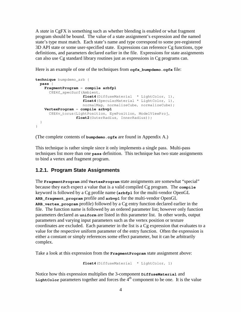
A state in CgFX is something such as whether blending is enabled or what fragment program should be bound. The value of a state assignment’s expression and the named state’s type must match. Each state’s name and type correspond to some pre-registered 3D API state or some user-specified state. Expressions can reference Cg functions, type definitions, and parameters declared earlier in the file. Expressions for state assignments can also use Cg standard library routines just as expressions in Cg programs can.
Here is an example of one of the techniques from cgfx_bumpdemo.cgfx file:
technique bumpdemo_arb { pass { FragmentProgram = compile arbfp1 C8E4f_specSurf(Ambient, float4(DiffuseMaterial * LightColor, 1), float4(SpecularMaterial * LightColor, 1), normalMap, normalizeCube, norm alizeCube); VertexProgram = compile arbvp1 C8E6v_torus(LightPosition, EyePosition, Model ViewProj, float2(OuterRadius, InnerRadius)); } }
(The complete contents of bumpdemo.cgfx are found in Appendix A.)
This technique is rather simple since it only implements a single pass. Multi-pass techniques list more than one pass definition. This technique has two state assignments to bind a vertex and fragment program.
1.2.1. Program State Assignments
The FragmentProgram and VertexProgram state assignments are somewhat “special” because they each expect a value that is a valid compiled Cg program. The compile keyword is followed by a Cg profile name (arbfp1 for the multi-vendor OpenGL ARB_fragment_program profile and arbvp1 for the multi-vendor OpenGL ARB_vertex_program profile) followed by a Cg entry function declared earlier in the file. The function name is followed by an ordered parameter list; however only function parameters declared as uniform are listed in this parameter list. In other words, output parameters and varying input parameters such as the vertex position or texture coordinates are excluded. Each parameter in the list is a Cg expression that evaluates to a value for the respective uniform parameter of the entry function. Often the expression is either a constant or simply references some effect parameter, but it can be arbitrarily complex.
Take a look at this expression from the FragmentProgram state assignment above:
float4(DiffuseMaterial * LightColor, 1)
Notice how this expression multiplies the 3-component DiffuseMaterial and LightColor parameters together and forces the 4th component to be one. It is the value
5
resulting from the evaluation of this expression that provides the value of the second uniform parameter (LMd) for the C8E4f_specSurf fragment program.
When a state assignment is set in the course of applying a technique (the Cg runtime API calls to set the state assignments of a pass are discussed later), the Cg runtime iterates in order over each state assignment for the selected pass. The Cg runtime evaluates expressions using the current values of any referenced effect parameters to determine the value for each state assignment. Then the Cg runtime assigns the resulting values to the corresponding state.
How does the Cg runtime evaluate expressions? In the course of the Cg runtime creating the effect, the Cg compiler (which exists within the Cg runtime) parses the effect and builds (compiles) each expression into a data structure that can be evaluated with a virtual machine (which also exists within the Cg runtime). Typically these expressions are quite simple (often merely constants or direct references to effect parameters) so the expense of evaluating such expressions is quite low.
As a consequence of setting a state assignment, the Cg runtime (or possibly a custom user-registered state callback) issues the appropriate 3D API commands associated with each state. In the case of the FragmentProgram and VertexProgram state assignments shown above, this means binding to the proper compiled program object and setting that program’s parameters to the respective value of each evaluated expression.
Once all the state assignments for a pass have been set, the application can render objects and the appropriate GPU processing occurs.
1.2.2. State Assignments for Other Non-programmable State
The state assignments for Cg programs are special because they involve the compilation of Cg programs. Other state assignments can control non-programmable 3D API state such as blending and are typically simpler to specify. For example, to make sure a pass enables SrcAlpha/OneMinusSrcAlpha blending, you could write this state assignment within a pass definition:
BlendEnable = true; BlendFunc = int2(SrcAlpha, OneMinusSrcAlpha);
These state assignments for BlendEnable and BlendFunc are registered to set the respective state within the conventional 3D hardware rendering pipeline. For a state such as BlendFunc that is most conveniently specified with enumerated names, such names are pre-registered for the state values.
Complex effects often involve the combination of state assignments for programmable and non-programmable states. With the CgFX runtime you can even register custom states to extend CgFX to handle unanticipated or effect-specific states.

6
1.3. Annotations
Along with Cg code and techniques, CgFX files can also associate annotations with each technique, pass, program, or effect parameter. An annotation is a typed name/value pair that can be queried (inspected) by applications using the Cg runtime. The purpose of an annotation is to associate some meta-information with the annotated object that an application can use to apply the effect properly.
Here is an example:
float3 DiffuseMaterial< string type = "color"; float3 minValue = float3(0,0,0); float3 maxValue = float3(1,1,1); > = { 0.9, 0.6, 0.3 };
The angle brackets after the effect parameter name DiffuseMaterial delimit a sequence of annotations. In this example, three annotations are specified.
How annotations are used is entirely application dependent. The expectation is that effect authors and 3D application developers desiring to share effects would agree to an appropriate set of annotations. For example, the type, minValue, and maxValue annotations would allow an effect editor to display a color chooser widget with the appropriate numeric range for setting the DiffuseMaterial effect parameter.
1.4. CgFX Runtime API Support
As of Cg Toolkit version 1.4, the Cg runtime API includes support for loading and using CgFX files. When we discuss cgfx_bumpdemo.c, we will see portions of this API for CgFX in action. Support for CgFX is not a layer upon Cg but rather a first-class capability implemented within the Cg runtime.
2. A Complete CgFX Demo
What follows is the complete source code for a CgFX-based version of cg_bumpdemo. Hence this new demo is called cgfx_bumpdemo.
The demo’s CgFX effect file, named bumpdemo.cgfx, contains two Cg programs taken directly from Chapter 8 (Bump Mapping) of The Cg Tutorial. The Cg programs are included in the appendix at the end of this article; please consult The Cg Tutorial for an explanation of the programs and the underlying bump mapping background and mathematics.
7
The demo renders with OpenGL and interfaces with the window system via the cross-platform OpenGL Utility Toolkit (GLUT).† To interface the application with the Cg programs, the demo calls the generic Cg and OpenGL-specific CgGL runtime routines.
OpenGL, GLUT, and the Cg and CgGL runtimes are supported on Windows, OS X, Linux, and Solaris so this demo compiles and runs on all of these operating systems. The demo automatically selects the most appropriate profile for your hardware. Cg supports multi-vendor OpenGL profiles (namely, arbvp1 and arbfp1) so the demo works on GPUs from ATI, NVIDIA, or any other OpenGL implementation, such as Brian Paul’s open source Mesa library, that exposes the multi-vendor ARB_vertex_program and ARB_fragment_program OpenGL extensions.
2.1. CgFX Demo Source Code Walkthrough
The cgfx_bumpdemo demo consists of the following four source files:
1. cgfx_bumpdemo.c—ANSI C source code for the CgFX-based demo. 2. brick_image.h—Header file containing RGB8 image data for a mipmapped
128x128 normal map for a brick pattern. 3. nmap_image.h—Header file containing RGB8 image data for a normalization
vector cube map with 32x32 faces. 4. cgfx_bumpdemo.cgfx—CgFX effect file.
Later, we will go through cgfx_bumpdemo.c line-by-line.
2.2. Pre-defined Texture Data
To keep the demo self-contained and maintain the focus on how the Cg runtime loads and configures the CgFX effect and then renders with the effect, this demo uses static texture image data included in the two header files. These two image data header files are the same ones used in the prior cg_bumpdemo example.
The data in these header files are used to construct OpenGL texture objects for a brick pattern normal map 2D texture and a “vector normalization” cube map. These texture objects are sampled by the fragment program.
The data in the two headers files consists of hundreds of comma-separated numbers (I’ll save you the tedium of publishing all the numbers in this article…). Rather than static data compiled into an executable, a typical application would read normal map textures from on-disk image files or convert a height-field image file to a normal map. Likewise,
† Documentation, source code, and pre-compiled GLUT libraries are available from http://www.opengl.org/developers/documentation/glut.html

8
a “normalization vector” cube map is typically procedurally generated rather than loaded from static data.
2.3. The Effect File Contents
The heart of the demo’s shading is encapsulated within the bumpdemo.cgfx effect file. The demo reads this effect file when the demo begins running. The demo uses the Cg runtime to create an effect from bumpdemo.cgfx and then selects a valid technique for rendering the demo’s bump-mapped torus.
2.3.1. Cg Programs within the Effect File
The CgFX file begins with the Cg vertex and fragment programs needed by the effect. These functions are explained in Chapter 8 (Bump Mapping) of The Cg Tutorial.
Rather than rehash the background, theory, and operation of these Cg programs, you should consult Chapter 8 of The Cg Tutorial. Pages 200 to 204 explain the construction of the brick pattern normal map. Pages 206 to 208 explain the construction and application of a normalization cube map. Pages 208 to 211 explains specular bump mapping, including the C8E4f_specSurf fragment program. Pages 211 to 218 explain texture-space bump mapping. Pages 218 to 224 explain the construction of the per-vertex coordinate system needed for texture-space bump mapping for the special case of an object (the torus) that is generated from parametric equations by the C8E6v_torus vertex program.
2.3.2. Effect Parameters within the Effect File
After the Cg programs in cgfx_bumpdemo.cgfx, there are a set of effect parameters. These effect parameters drive the input parameters for the Cg programs.
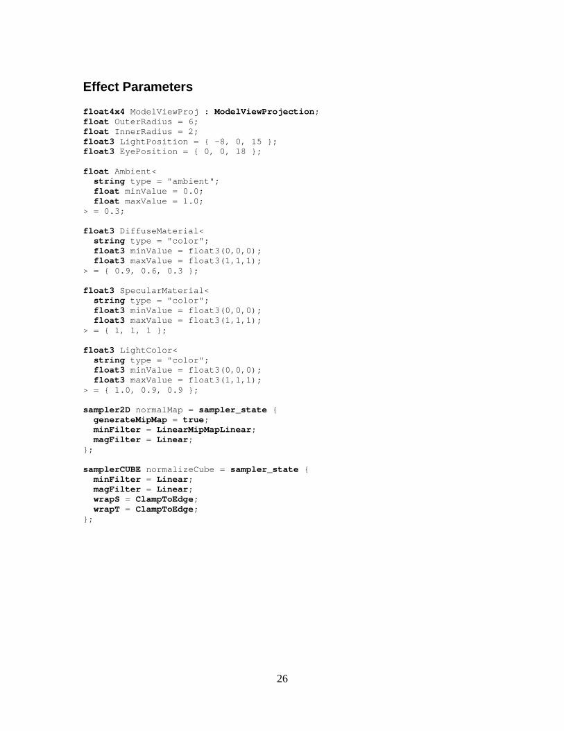
Most of the effect parameters have reasonable default initializations and so can simply be left alone. These include the torus size parameters (OuterRadius and InnerRadius) and the light and material colors (Ambient, DiffuseMaterial, SpecularMaterial, and LightColor). Providing a default value for an effect parameter is simply a matter of assigning a value to the parameter. Example:
float OuterRadius = 6; float InnerRadius = 2;
9
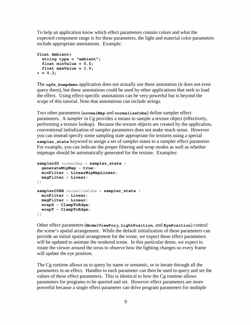
To help an application know which effect parameters contain colors and what the expected component range is for these parameters, the light and material color parameters include appropriate annotations. Example:
float Ambient< string type = "ambient"; float minValue = 0.0; float maxValue = 1.0; > = 0.3;
The cgfx_bumpdemo application does not actually use these annotation (it does not even query them), but these annotations could be used by other applications that seek to load the effect. Using effect-specific annotations can be very powerful but is beyond the scope of this tutorial. Note that annotations can include strings.
Two other parameters (normalMap and normalizeCube) define sampler effect parameters. A sampler in Cg provides a means to sample a texture object (effectively, performing a texture lookup). Because the texture objects are created by the application, conventional initialization of sampler parameters does not make much sense. However you can instead specify some sampling state appropriate for textures using a special sampler_state keyword to assign a set of sampler states to a sampler effect parameter. For example, you can indicate the proper filtering and wrap modes as well as whether mipmaps should be automatically generated for the texture. Examples:
sampler2D normalMap = sampler_state { generateMipMap = true; minFilter = LinearMipMapLinear; magFilter = Linear; }; samplerCUBE normalizeCube = sampler_state { minFilter = Linear; magFilter = Linear; wrapS = ClampToEdge; wrapT = ClampToEdge; };
Other effect parameters (ModelViewProj, LightPosition, and EyePosition) control the scene’s spatial arrangement. While the default initialization of these parameters can provide an initial spatial arrangement for the scene, we expect these effect parameters will be updated to animate the rendered scene. In this particular demo, we expect to rotate the viewer around the torus to observe how the lighting changes so every frame will update the eye position.
The Cg runtime allows us to query by name or semantic, or to iterate through all the parameters in an effect. Handles to each parameter can then be used to query and set the values of these effect parameters. This is identical to how the Cg runtime allows parameters for programs to be queried and set. However effect parameters are more powerful because a single effect parameter can drive program parameters for multiple
10
programs belonging to different passes of different techniques. Also since program parameters in a vertex or fragment program state assignment are specified as expressions, they can combine multiple effect parameters to compute each program parameter for the vertex or fragment program.
As we will see, an effect can be parameterized with high-level effect parameters that drive program parameters automatically. For example, the C8E4f_specSurf fragment program expects its parameter named LMd to contain the light color and diffuse material color pre-multiplied together. Likewise its LMs parameter expects to contain the light color and specular material color pre-multiplied together. Effect parameters allow us to specify the light color, the diffuse material color, and specular material color independently and have the Cg runtime perform the necessary pre-multiplication.
Because effect parameters drive the values of program parameters through programmable expressions, effect parameters can be more abstract than program parameters without compromising the performance of vertex and fragment programs.
2.3.3. Techniques within the Effect File
Once some effect parameters and Cg parameters have been specified, we can specify a set of techniques that use those Cg programs and effect parameters.
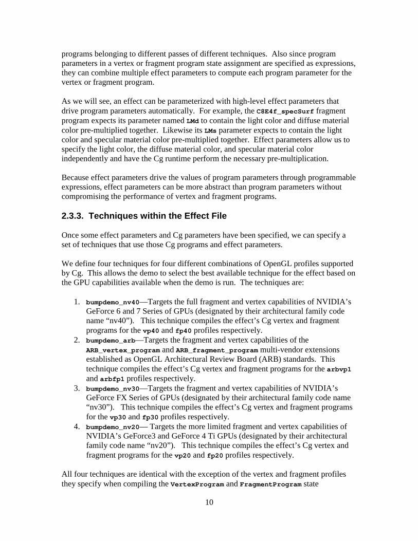
We define four techniques for four different combinations of OpenGL profiles supported by Cg. This allows the demo to select the best available technique for the effect based on the GPU capabilities available when the demo is run. The techniques are:
1. bumpdemo_nv40—Targets the full fragment and vertex capabilities of NVIDIA’s GeForce 6 and 7 Series of GPUs (designated by their architectural family code name “nv40”). This technique compiles the effect’s Cg vertex and fragment programs for the vp40 and fp40 profiles respectively.
2. bumpdemo_arb—Targets the fragment and vertex capabilities of the ARB_vertex_program and ARB_fragment_program multi-vendor extensions established as OpenGL Architectural Review Board (ARB) standards. This technique compiles the effect’s Cg vertex and fragment programs for the arbvp1 and arbfp1 profiles respectively.
3. bumpdemo_nv30—Targets the fragment and vertex capabilities of NVIDIA’s GeForce FX Series of GPUs (designated by their architectural family code name “nv30”). This technique compiles the effect’s Cg vertex and fragment programs for the vp30 and fp30 profiles respectively.
4. bumpdemo_nv20— Targets the more limited fragment and vertex capabilities of NVIDIA’s GeForce3 and GeForce 4 Ti GPUs (designated by their architectural family code name “nv20”). This technique compiles the effect’s Cg vertex and fragment programs for the vp20 and fp20 profiles respectively.
All four techniques are identical with the exception of the vertex and fragment profiles they specify when compiling the VertexProgram and FragmentProgram state

11
assignments. This allows each technique to be specialized to the capabilities of a specific GPU architecture for optimal performance.
They are all quite similar and the bumpdemo_arb technique has already been listed earlier so here is the bumpdemo_nv40 technique:
technique bumpdemo_nv40 { pass { FragmentProgram = compile fp40 C8E4f_specSurf(Ambient, float4(DiffuseMaterial * LightColor, 1), float4(SpecularMaterial * LightColor, 1), normalMap, normalizeCube, norm alizeCube); VertexProgram = compile vp40 C8E6v_torus(LightPosition, EyePosition, Model ViewProj, float2(OuterRadius, InnerRadius)); } }
While these techniques are different only in their Cg profiles, a given technique for an effect could be implemented differently, often using entirely different Cg programs. For example, one technique might account for shadowing for more realism while another version of the same effect might skip shadows or compute intermediate values with more precision.
3. On to the C Code
Now that we understand the effect that cgfx_bumpdemo will use, it’s time to dissect cgfx_bumpdemo.c line-by-line as promised (we’ll skip comments in the source code if the comments are redundant with the discussion below).
3.1. Initial Declarations
#include <math.h> #include <stdlib.h> #include <stdio.h> #include <GL/glut.h> #include <Cg/cg.h> #include <Cg/cgGL.h>
The first three includes are basic ANSI C standard library includes. We will be using sin, cos, printf, exit, and NULL. We rely on the GLUT header file to include the necessary OpenGL and OpenGL Utility Library (GLU) headers.
The <Cg/cg.h> header contains generic routines for loading and compiling Cg programs and CgFX effects but does not contain routines that call the 3D API to configure the Cg programs and CgFX effects for rendering. The generic Cg routines begin with a cg prefix; the generic Cg types begin with a CG prefix; and the generic Cg macros and enumerations begin with a CG_ prefix.

12
The <Cg/cgGL.h> contains the OpenGL-specific routines for configuring Cg programs for rendering with OpenGL. The OpenGL-specific Cg routines begin with a cgGL prefix; the OpenGL-specific Cg types begin with a CGGL prefix; and the OpenGL-specific Cg macros and enumerations begin with a CGGL_ prefix.
Technically, the <Cg/cgGL.h> header includes <Cg/cg.h> so we do not have to explicitly include <Cg/cg.h> but we include both to remind you that we will be calling both generic Cg routines and OpenGL-specific Cg routines.
3.1.1. Cg Runtime Variables
Next, we will list all global variables we plan to use. We use the my prefix to indicate global variables that we define (to make it crystal clear what names we are defining rather than those names defined by header files). When we declare a variable of a type defined by the Cg runtime, we use the myCg prefix to remind you that the variable is for use with the Cg runtime.
CGcontext myCgContext; CGeffect myCgEffect; CGtechnique myCgTechnique; CGparameter myCgEyePositionParam, myCgModelViewProjParam;
These are the global Cg runtime variables the demo initializes and uses. We need a single Cg compilation context (myCgContext). Think of your Cg compilation context as the “container” for all the Cg handles you manipulate. Typically your program requires just one Cg compilation context.
We need one Cg effect (myCgEffect) for when we load bumpdemo.cgfx.
We need one Cg technique (myCgTechnique) for the particular technique we will use to render the torus. While there are four possible techniques, we will select the first technique valid for the GPU upon which the demo is actually running.
We need handles for the two effect parameters that we plan to set as the demo animates. We do not plan to change the default initialization of most of the effect parameters so we need not keep effect parameter handles for these parameters.
In a real program, you’ll probably have more Cg effects, techniques, and effect parameters than shown in this simple example. You may have hundreds depending on how complicated the shading is in your application. Keep in mind that this demo is trying to be very simple.

13
3.1.2. Demo Initialization
static void initCg(); static void initOpenGL(); static void display(void); static void keyboard(unsigned char c, int x, int y);
The demo first declares various routines, described later, used by the demo’s main routine.
int main( int argc, char **argv) { glutInitDisplayMode( GLUT_RGB | GLUT_DOUBLE | GLUT_DEPTH); glutInitWindowSize(400, 400); glutInit(&argc, argv); glutCreateWindow("cgfx_bumpdemo");
The main routine creates a GLUT window with an associated OpenGL rendering context.
initCgFX(); initOpenGL();
Then CgFX objects are initialized along with OpenGL rendering state.
glutDisplayFunc(display); glutKeyboardFunc(keyboard); glutMainLoop(); return 0; }
The demo registers callbacks for displaying the window, resizing the window, and accepting keyboard input. Finally GLUT event processing begins.
3.1.3. Error Reporting Helper Routine
Cg initialization depends on a helper routine for reporting Cg-related errors:
static void checkForCgError( const char *situation) { CGerror error; const char *string = cgGetLastErrorString(&error); if (error != CG_NO_ERROR) { printf("cgfx_bumpdemo: %s: %s\n", situation, string); if (error == CG_COMPILER_ERROR) { printf("%s\n", cgGetLastListing(myCgContext)); } exit(1); } }
Cg runtime routines report errors by setting a global error value. Calling the cgGetLastErrorString routine both returns a human-readable string describing the last
14
generated Cg error and writes an error code of type CGerror. CG_NO_ERROR (defined to be zero) means there was no error. As a side-effect, cgGetLastErrorString also resets the global error value to CG_NO_ERROR. The Cg runtime also includes the simpler function cgGetError that just returns and then resets the global error code if you just want the error code and don’t need a human-readable string too.
The checkForCgError routine is used to ensure proper error checking within the demo. If an error has occurred, the routine prints an error message including the situation string and translated Cg error value string, and then exits the demo.
When the error returned is CG_COMPILER_ERROR that means there are also compiler error messages. So checkForCgError then calls cgGetLastListing to obtain a pointer to the compiler error message and prints it out too. For example, if your CgFX effect file had a syntax error, you’d see the compiler’s error messages including the line numbers where the compiler identified problems.
While “just exiting” is fine for a demo, real applications will want to properly handle any errors generated. In general, you don’t have to be so paranoid as to call cgGetLastErrorString after every Cg runtime routine. Check the runtime API documentation for each routine to see the reasons it can fail; when in doubt, check for failures.
3.1.4. Cg Initialization
static void initCgFX(void) { myCgContext = cgCreateContext(); checkForCgError("creating Cg context"); cgGLRegisterStates(myCgContext); cgGLSetManageTextureParameters(myCgContext, CG_TRUE); checkForCgError("configuring Cg context");
First we create a Cg context, register the standard states (if you fail to do this, your Cg context will lack the standard states needed for processing standard 3D API state assignments—alternatively you could load your own implementations of the standard CgFX states), and request that the Cg runtime manage texture binds (saving your application the trouble when applying techniques).
myCgEffect = cgCreateEffectFromFile(myCgContext, "bumpdemo.cgfx", NULL); checkForCgError("creating bumpdemo.cgfx effect");

15
Now we read the bumpdemo.cgfx effect file to create an effect.
myCgTechnique = cgGetFirstTechnique(myCgEffect); while (myCgTechnique && cgValidateTechnique(myCgTechniqu e) == CG_FALSE) { fprintf( stderr, "cgfx_bumpdemo: Technique %s did not validate . Skipping.\n", cgGetTechniqueName(myCgTechnique)); myCgTechnique = cgGetNextTechnique(myCgTechnique); } if (myCgTechnique) { fprintf( stderr, "cgfx_bumpdemo: Using technique %s.\n", cgGetTechniqueName(myCgTechnique)); } else { fprintf( stderr, "cgfx_bumpdemo: No valid technique\n"); exit(1); }
We iterate in order through the techniques defined by the effect. We attempt to validate each technique. This is because the techniques are listed in the effect file in roughly the order of most-optimal to least-optimal. As soon as we find a technique that is valid for our GPU, we choose that technique and go on. If we find no valid technique, our GPU is not capable of rendering the effect so we exit with an error.
myCgModelViewProjParam = cgGetEffectParameterBySemantic(myCgEffect, "ModelViewProjection"); if (!myCgModelViewProjParam) { fprintf( stderr, "cgfx_bumpdemo: no parameter with ModelViewPr ojection semantic\n"); exit(1); } myCgEyePositionParam = cgGetNamedEffectParameter(myCgEffect, "EyePosition"); if (!myCgEyePositionParam) { fprintf( stderr, "cgfx_bumpdemo: no parameter named EyePosition\n" ); exit(1); } }
As discussed earlier, most of the effect parameters have appropriate defaults. However if we want to set effect parameters to other values, we need to query a handle for such effect parameters. In this case, we want to animate the eye position and track OpenGL’s modelview and projection matrices.
We can query effect parameters by iterating through the entire list (with cgGetFirstEffectParameter and cgGetNextParameter) or query the effect parameters by either name or semantic as shown above. Once we have the handle to an effect parameter we can query its name, type, value, semantic, and other information. We can also set its value and other properties.
A more sophisticated demo would iterate over and query all the effect parameters and inspect their annotations to determine how to interface the application’s data to the effect.
16
This allows such demos to operate with a much boarder range of effects. This demo is intentionally simplistic so it just queries by name the parameters it expects.
3.1.5. Texture Data
Before explaining how we initialize OpenGL, for completeness we discuss how the necessary textures are loaded. This code exactly matches the cg_bumpdemo source code.
/* OpenGL texture object (TO) handles. */ enum { TO_NORMALIZE_VECTOR_CUBE_MAP = 1, TO_NORMAL_MAP = 2, };
The TO_ prefixed enumerants provide numbers for use as OpenGL texture object names.
static const GLubyte myBrickNormalMapImage[3*(128*128+64*64+32*32+16*16+ 8*8+4*4+2*2+1*1)] = { /* RGB8 image data for mipmapped 128x128 normal map for a brick pattern */ #include "brick_image.h" }; static const GLubyte myNormalizeVectorCubeMapImage[6*3*32*32] = { /* RGB8 image data for normalization vector cube ma p with 32x32 faces */ #include "normcm_image.h" };
These static, constant arrays include the header files containing the data for the normal map’s brick pattern and the “normalization vector” cube map. Each texel is 3 unsigned bytes (one for red, green, and blue). While each byte of the texel format is unsigned, normal map components, as well as the vector result of normalizing an arbitrary direction vector, are logically signed values within the [-1,1] range. To accommodate signed values with OpenGL’s conventional GL_RGB8 unsigned texture format, the unsigned [0,1] range is expanded in the fragment program to a signed [-1,1] range. This is the reason for the expand helper function called by the C8E4f_specSurf fragment program (see Appendix A).
The normal map has mipmaps so there is data for the 128x128 level, and then, each of the successively downsampled mipmap levels. However this version of the demo asks the driver to generate the mipmaps for the normal map instead by using a sampler state assignment to request mipmap generation.
The “normalization vector” cube map has six 32x32 faces without mipmaps.
3.1.6. Initializing Sampler Effect Parameters
To fully initialize the OpenGL state required, we need to associate the OpenGL texture objects for the normal map and normalization cube map textures with their respective sampler effect parameters.
17
static void useSamplerParameter( CGeffect effect, const char *paramName, GLuint texobj) { CGparameter param; param = cgGetNamedEffectParameter(effect, paramName); if (!param) { fprintf( stderr, "cgfx_bumpdemo: expected effect parameter named % s\n", paramName); exit(1); } cgGLSetTextureParameter(param, texobj); cgSetSamplerState(param); }
We query the named effect parameter and then use cgGLSetTextureParameter to set an OpenGL texture object for the sampler. Next we use cgSetSamplerState to make the appropriate OpenGL calls to set the sampler_state state settings for the sampler effect parameter. This ensures each sampler’s texture object is configured with the effect’s intended filtering and wrap modes and mipmap generation occurs if requested.
3.1.7. OpenGL Rendering State Initialization
static void initOpenGL( void) { const GLubyte *image; unsigned int face; glPixelStorei( GL_UNPACK_ALIGNMENT, 1); /* Tightly packed texture data. */
By default, OpenGL’s assumes each image scanline is aligned to begin on 4 byte boundaries. However, RGB8 data (3 bytes per pixel) is usually tightly packed so a 1 byte alignment is appropriate. That’s indeed the case for the RGB8 pixels in our static arrays used to initialize our textures. If you didn’t know about this OpenGL pitfall before, you do now.‡
‡ Being aware of pitfalls such as this one can save you a lot of time debugging. This and other OpenGL pitfalls are enumerated in my article “Avoiding 19 Common OpenGL Pitfalls” found here http://developer.nvidia.com/object/Avoiding_Common_ogl_Pitfalls.html An earlier HTML version of the article (with just 16 pitfalls) is found here http://www.opengl.org/developers/code/features/KilgardTechniques/oglpitfall/oglpitfall.html

18
/* OpenGL tokens for cube maps missing from Windows version of <GL/gl.h> */ #define GL_TEXTURE_CUBE_MAP 0x8513 #define GL_TEXTURE_CUBE_MAP_POSITIVE_X 0x8515 glBindTexture( GL_TEXTURE_CUBE_MAP, TO_NORMALIZE_VECTOR_CUBE_MAP); useSamplerParameter(myCgEffect, "normalizeCube", TO_NORMALIZE_VECTOR_CUBE_MAP) ; /* Load each 32x32 face (without mipmaps) of rang e-compressed "normalize vector" cube map. */ for (face = 0, image = myNormalizeVectorCubeMapImage; face < 6; face++, image += 3*32*32) { glTexImage2D( GL_TEXTURE_CUBE_MAP_POSITIVE_X + face, 0, GL_RGB8, 32, 32, 0, GL_RGB, GL_UNSIGNED_BYTE, image); }
First we bind the texture object for the “normalization vector” cube map§ intended to quickly normalize the 3D lighting vectors that are passed as texture coordinates. Calling useSamplerParameter binds this effect’s sampler to the just created normalization cube map and sets the sampler state as requested by the effect. The cube map texture has six faces but there is no need for mipmaps. Each face is packed into the myNormalizeVectorCubeMapImage array right after the prior face with the faces ordered in the order of the sequential texture cube map face OpenGL enumerants.
glBindTexture( GL_TEXTURE_2D, TO_NORMAL_MAP); useSamplerParameter(myCgEffect, "normalMap", TO_NORMAL_MAP); glTexImage2D( GL_TEXTURE_2D, 0, GL_RGB8, 128, 128, 0, GL_RGB, GL_UNSIGNED_BYTE, myBrickNormalMapImage );
Next we bind to the texture object for our brick pattern normal map 2D texture, call useSamplerParameter to bind this effect’s sampler to the just created normal map and set the sampler state as requested by the effect, and then load the base level of the normal map (from which mipmaps will be automatically generated because mipmap generation is specified in the effect parameter’s sampler_state initialization).
glEnable( GL_DEPTH_TEST); glMatrixMode( GL_PROJECTION); glLoadIdentity(); gluPerspective( 60.0, /* Field of view in degree */ 1.0, /* Aspect ratio */ 0.1, /* Z near */ 100.0); /* Z far */ glMatrixMode( GL_MODELVIEW); glClearColor(0.1, 0.3, 0.6, 0.0); /* Blue background */ }
§ Using a “normalization vector” cube map allows our demo to work on older DirectX 8-class GPUs that lacked the shading generality to normalize vectors mathematically. Ultimately as more capable GPUs become ubiquitous, use of normalization cube maps is sure to disappear in favor of normalizing a vector mathematically. A technique using a different Cg program could use Cg’s normalize standard library routine instead.

19
Finally we enable depth testing, establish a perspective projection transform, and set the background color to blue. Alternatively we could enable the depth test in a state assignment within each technique’s pass but this would set the depth test every time we apply the technique. It is easier to simply leave the depth test always enabled since we never need it disabled for this demo.
3.2. Displaying the Window
Earlier in the code, we forward declared the display callback. Now is the time to discuss what the display routine does and how exactly we render our bump-mapped torus using the textures and Cg vertex and fragment programs we’ve loaded.
3.2.1. Rendering a 2D Mesh to Generate a Torus
In the course of updating the window, the display callback invokes the drawFlatPatch subroutine. This subroutine renders a flat 2D mesh with immediate-mode OpenGL commands. This routine is unchanged from the cg_bumpdemo version of this demo.
/* Draw a flat 2D patch that can be "rolled & bent" into a 3D torus by a vertex program. */ void drawFlatPatch( float rows, float columns) { const float m = 1.0f/columns; const float n = 1.0f/rows; int i, j; for (i=0; i<columns; i++) { glBegin( GL_QUAD_STRIP); for (j=0; j<=rows; j++) { glVertex2f(i*m, j*n); glVertex2f((i+1)*m, j*n); } glVertex2f(i*m, 0); glVertex2f((i+1)*m, 0); glEnd(); } }
The mesh consists of a number of adjacent quad strips. The C8E6v_torus vertex program will take these 2D vertex coordinates and use them as parametric coordinates for evaluating the position of vertices on a torus.
Nowadays it’s much faster to use OpenGL vertex arrays, particularly with vertex buffer objects, to render geometry, but for this simple demo, immediate mode rendering is easier.
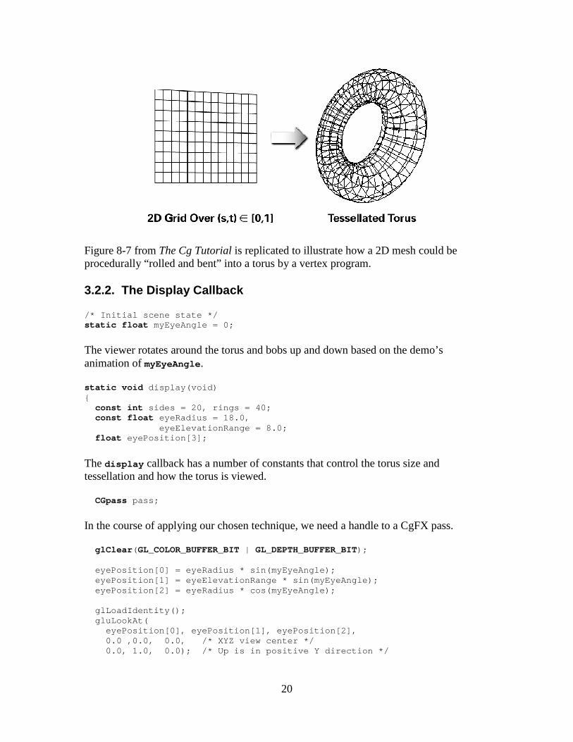
20
Figure 8-7 from The Cg Tutorial is replicated to illustrate how a 2D mesh could be procedurally “rolled and bent” into a torus by a vertex program.
3.2.2. The Display Callback
/* Initial scene state */ static float myEyeAngle = 0;
The viewer rotates around the torus and bobs up and down based on the demo’s animation of myEyeAngle.
static void display(void) { const int sides = 20, rings = 40; const float eyeRadius = 18.0, eyeElevationRange = 8.0; float eyePosition[3];
The display callback has a number of constants that control the torus size and tessellation and how the torus is viewed.
CGpass pass;
In the course of applying our chosen technique, we need a handle to a CgFX pass.
glClear( GL_COLOR_BUFFER_BIT | GL_DEPTH_BUFFER_BIT); eyePosition[0] = eyeRadius * sin(myEyeAngle); eyePosition[1] = eyeElevationRange * sin(myEyeAng le); eyePosition[2] = eyeRadius * cos(myEyeAngle); glLoadIdentity(); gluLookAt( eyePosition[0], eyePosition[1], eyePosition[2], 0.0 ,0.0, 0.0, /* XYZ view center */ 0.0, 1.0, 0.0); /* Up is in positive Y direct ion */
21
The viewing transform is re-specified each frame. The eye position is a function of myEyeAngle. By animating this variable, the viewer rotates around the torus with a sinusoidally varying elevation. Because specular bump mapping is view-dependent, the specular lighting varies over the torus as the viewer rotates around.
cgGLSetStateMatrixParameter(myCgModelViewProjPara m, CG_GL_MODELVIEW_PROJECTION_MATRIX, CG_GL_MATRIX_IDENTITY); cgSetParameter3fv(myCgEyePositionParam, eyePositi on);
We set the effect parameter for the modelview-projection matrix to the current OpenGL modelview-projection matrix (even though in this demo we aren’t actually changing it—we could move and rotate the torus if we did).
pass = cgGetFirstPass(myCgTechnique); while (pass) { cgSetPassState(pass);
This begins the “guts” of the rendering where we apply our chosen technique. All our techniques involve only a single pass, but the code is written so it could iterate through a sequence of passes if our technique did provide multiple passes.
We get the first pass for our chosen technique with cgGetFirstPass. Then cgSetPassState sets all the state assignments for the pass. This includes evaluating as necessary any state assignment expressions to determine their updated values. The appropriate OpenGL API commands are issued to bind to the pass’s vertex and fragment program (as established when we called cgGLRegisterStates from main).
drawFlatPatch(sides, rings);
Then we render the flat patch with drawFlatPatch which renders the bump-mapped torus using the effect loaded from bumpdemo.cgfx.
cgResetPassState(pass);
We clean up any OpenGL state modified by cgSetPassState by calling cgResetPassState. In this case, the state is restored to OpenGL’s initial state. This helps keep our state assignments from unintentionally affecting subsequent rendering.
pass = cgGetNextPass(pass); }
We request the next pass in the technique and repeat until we run out of passes. All four techniques in our effect only have a single pass so this is not really necessary. But it but would be if multi-pass techniques were involved.
glutSwapBuffers(); }
22
We complete the rendering by performing a buffer swap to display the results.
3.3. Keyboard Processing
Along with the display callback, we also forward declared and registered the keyboard callback. Now it’s time to see how the demo responses to simple keyboard input. This code is unchanged from the original cg_bumpdemo source code.
3.3.1. Animating the Eye Position
static void advanceAnimation( void) { myEyeAngle += 0.05f; if (myEyeAngle > 2*3.14159) myEyeAngle -= 2*3.14159; glutPostRedisplay(); }
In order to animate the changing eye position so the view varies, the advanceAnimation callback is registered as the GLUT idle function. The routine advances myEyeAngle and posts a request for GLUT to redraw the window with glutPostRedisplay. GLUT calls the idle function repeatedly when there are no other events to process.
3.3.2. The Keyboard Callback
static void keyboard( unsigned char c, int x, int y) { static int animating = 0; switch (c) { case ' ': animating = !animating; /* Toggle */ glutIdleFunc(animating ? advanceAnimation : NULL); break;
The space bar toggles animation of the scene by registering and de-registering the advanceAnimation routine as the idle function.
case 27: /* Esc key */ cgDestroyEffect(myCgEffect); cgDestroyContext(myCgContext); exit(0); break; } }
The Esc key exits the demo. While it is not necessary to do so since the demo is exiting, the calls to cgDestroyEffect and cgDestroyContext deallocate the Cg runtime objects, along with their associated OpenGL state.
23
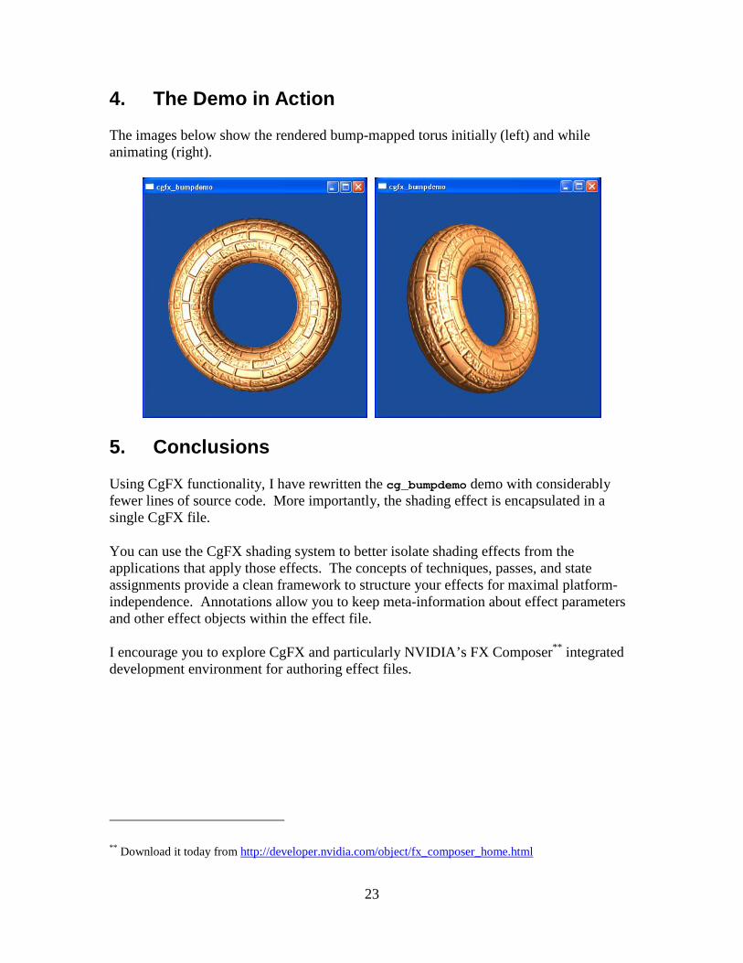
4. The Demo in Action
The images below show the rendered bump-mapped torus initially (left) and while animating (right).
5. Conclusions
Using CgFX functionality, I have rewritten the cg_bumpdemo demo with considerably fewer lines of source code. More importantly, the shading effect is encapsulated in a single CgFX file.
You can use the CgFX shading system to better isolate shading effects from the applications that apply those effects. The concepts of techniques, passes, and state assignments provide a clean framework to structure your effects for maximal platform-independence. Annotations allow you to keep meta-information about effect parameters and other effect objects within the effect file.
I encourage you to explore CgFX and particularly NVIDIA’s FX Composer** integrated development environment for authoring effect files.
** Download it today from http://developer.nvidia.com/object/fx_composer_home.html

24
Appendix A: bumpdemo.cgfx Effect File
Cg Vertex Program
void C8E6v_torus( float2 parametric : POSITION, out float4 position : POSITION, out float2 oTexCoord : TEXCOORD0, out float3 lightDirection : TEXCOORD1, out float3 halfAngle : TEXCOORD2, uniform float3 lightPosition, // Object-space uniform float3 eyePosition, // Object-space uniform float4x4 modelViewProj, uniform float2 torusInfo) { const float pi2 = 6.28318530; // 2 times Pi // Stetch texture coordinates counterclockwise // over torus to repeat normal map in 6 by 2 patt ern float M = torusInfo[0]; float N = torusInfo[1]; oTexCoord = parametric * float2(-6, 2); // Compute torus position from its parameteric eq uation float cosS, sinS; sincos(pi2 * parametric.x, sinS, cosS); float cosT, sinT; sincos(pi2 * parametric.y, sinT, cosT); float3 torusPosition = float3((M + N * cosT) * cosS, (M + N * cosT) * si nS, N * sinT); position = mul(modelViewProj, float4(torusPosition, 1)); // Compute per-vertex rotation matrix float3 dPds = float3(-sinS*(M+N*cosT), cosS*(M+N*cosT), 0 ); float3 norm_dPds = normalize(dPds); float3 normal = float3(cosS * cosT, sinS * cosT, sinT); float3 dPdt = cross(normal, norm_dPds); float3x3 rotation = float3x3(norm_dPds, dPdt, normal); // Rotate object-space vectors to texture space float3 eyeDirection = eyePosition - torusPosition; lightDirection = lightPosition - torusPosition; lightDirection = mul(rotation, lightDirection); eyeDirection = mul(rotation, eyeDirection); halfAngle = normalize( normalize(lightDirection) + normalize(eyeDirection)); }
25
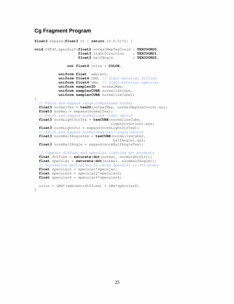
Cg Fragment Program
float3 expand( float3 v) { return (v-0.5)*2; } void C8E4f_specSurf( float2 normalMapTexCoord : TEXCOORD0, float3 lightDirection : TEXCOORD1, float3 halfAngle : TEXCOORD2, out float4 color : COLOR, uniform float ambient, uniform float4 LMd, // Light-material diffuse uniform float4 LMs, // Light-material specular uniform sampler2D normalMap, uniform samplerCUBE normalizeCube, uniform samplerCUBE normalizeCube2) { // Fetch and expand range-compressed normal float3 normalTex = tex2D(normalMap, normalMapTexCoord).xyz; float3 normal = expand(normalTex); // Fetch and expand normalized light vector float3 normLightDirTex = texCUBE(normalizeCube, lightDirection). xyz; float3 normLightDir = expand(normLightDirTex); // Fetch and expand normalized half-angle vector float3 normHalfAngleTex = texCUBE(normalizeCube2, halfAngle).xyz; float3 normHalfAngle = expand(normHalfAngleTex); // Compute diffuse and specular lighting dot prod ucts float diffuse = saturate( dot(normal, normLightDir)); float specular = saturate( dot(normal, normHalfAngle)); // Successive multiplies to raise specular to 8th power float specular2 = specular*specular; float specular4 = specular2*specular2; float specular8 = specular4*specular4; color = LMd*(ambient+diffuse) + LMs*specular8; }
26
Effect Parameters
float4x4 ModelViewProj : ModelViewProjection; float OuterRadius = 6; float InnerRadius = 2; float3 LightPosition = { -8, 0, 15 }; float3 EyePosition = { 0, 0, 18 }; float Ambient< string type = "ambient"; float minValue = 0.0; float maxValue = 1.0; > = 0.3; float3 DiffuseMaterial< string type = "color"; float3 minValue = float3(0,0,0); float3 maxValue = float3(1,1,1); > = { 0.9, 0.6, 0.3 }; float3 SpecularMaterial< string type = "color"; float3 minValue = float3(0,0,0); float3 maxValue = float3(1,1,1); > = { 1, 1, 1 }; float3 LightColor< string type = "color"; float3 minValue = float3(0,0,0); float3 maxValue = float3(1,1,1); > = { 1.0, 0.9, 0.9 }; sampler2D normalMap = sampler_state { generateMipMap = true; minFilter = LinearMipMapLinear; magFilter = Linear; }; samplerCUBE normalizeCube = sampler_state { minFilter = Linear; magFilter = Linear; wrapS = ClampToEdge; wrapT = ClampToEdge; };

27
Techniques
// Because cgfx_bumpdemo.c picks the first valid te chnique, // list techniques in relative order of preference. .. technique bumpdemo_nv40 { pass { FragmentProgram = compile fp40 C8E4f_specSurf(Ambient, float4(DiffuseMaterial * LightColor, 1), float4(SpecularMaterial * LightColor, 1), normalMap, normalizeCube, norm alizeCube); VertexProgram = compile vp40 C8E6v_torus(LightPosition, EyePosition, Model ViewProj, float2(OuterRadius, InnerRadius)); } } technique bumpdemo_nv30 { pass { FragmentProgram = compile fp30 C8E4f_specSurf(Ambient, float4(DiffuseMaterial * LightColor, 1), float4(SpecularMaterial * LightColor, 1), normalMap, normalizeCube, norm alizeCube); VertexProgram = compile vp30 C8E6v_torus(LightPosition, EyePosition, Model ViewProj, float2(OuterRadius, InnerRadius)); } } technique bumpdemo_arb { pass { FragmentProgram = compile arbfp1 C8E4f_specSurf(Ambient, float4(DiffuseMaterial * LightColor, 1), float4(SpecularMaterial * LightColor, 1), normalMap, normalizeCube, norm alizeCube); VertexProgram = compile arbvp1 C8E6v_torus(LightPosition, EyePosition, Model ViewProj, float2(OuterRadius, InnerRadius)); } } technique bumpdemo_nv20 { pass { FragmentProgram = compile fp20 C8E4f_specSurf(Ambient, float4(DiffuseMaterial * LightColor, 1), float4(SpecularMaterial * LightColor, 1), normalMap, normalizeCube, norm alizeCube); VertexProgram = compile vp20 C8E6v_torus(LightPosition, EyePosition, Model ViewProj, float2(OuterRadius, InnerRadius)); } }