a field guide to irrigation in the lower rio grande valley
TRANSCRIPT

A Field Guide toIrrigation in the
Lower Rio Grande Valley
Texas DeparTmenT of TransporTaTion
environmental affairs Division, Historical studies Branch
Historical studies report no. 2009-01
By Lila Knight

Prepared by Knight & Associates
P.O. Box 67, Buda, Texas 78610
2009
Environmental Affairs Division Work Authorization 576-15-SH002
Prepared For
The Creation of a Magic Valley
Irrigation in the Lower Rio Grande Valley

Table of Contents
Acknowledgements . . . . . . . . . . . . . . . . . . . . . . . . . . . . . . . . . . . . . . . . . . . . . . . . . . . . . . . . 1
Executive Summary . . . . . . . . . . . . . . . . . . . . . . . . . . . . . . . . . . . . . . . . . . . . . . . . . . . . . . . . . 4
Current Irrigation Districts of the Lower Rio Grande Valley . . . . . . . . . . . . . . . . . . . . . . . . . . . . 6
Historic Context . . . . . . . . . . . . . . . . . . . . . . . . . . . . . . . . . . . . . . . . . . . . . . . . . . . . . . . . . . . . 7
Character Defining Features of Irrigation Structures . . . . . . . . . . . . . . . . . . . . . . . . . . . . . . . 92
Introduction . . . . . . . . . . . . . . . . . . . . . . . . . . . . . . . . . . . . . . . . . . . . . . . . . . . . . . . . . . 93
Diversion Features . . . . . . . . . . . . . . . . . . . . . . . . . . . . . . . . . . . . . . . . . . . . . . . . . . . . . 100
Conveyance Features . . . . . . . . . . . . . . . . . . . . . . . . . . . . . . . . . . . . . . . . . . . . . . . . . . . 119
Distribution Features . . . . . . . . . . . . . . . . . . . . . . . . . . . . . . . . . . . . . . . . . . . . . . . . . . . 144
Delivery Features . . . . . . . . . . . . . . . . . . . . . . . . . . . . . . . . . . . . . . . . . . . . . . . . . . . . . . 168
Infrastructure . . . . . . . . . . . . . . . . . . . . . . . . . . . . . . . . . . . . . . . . . . . . . . . . . . . . . . . . 184
Associated Buildings and Structures . . . . . . . . . . . . . . . . . . . . . . . . . . . . . . . . . . . . . . . 194
Guidlines for Evaluating Irrigation Systems . . . . . . . . . . . . . . . . . . . . . . . . . . . . . . . . . . . . . 220
Introduction . . . . . . . . . . . . . . . . . . . . . . . . . . . . . . . . . . . . . . . . . . . . . . . . . . . . . . . . . 221
Irrigation Systems as Individual Structures . . . . . . . . . . . . . . . . . . . . . . . . . . . . . . . . . . 223
Assessing NRHP Eligibility of Segments . . . . . . . . . . . . . . . . . . . . . . . . . . . . . . . . . . . . 229
Assessing NRHP Eligibility of Individual Components . . . . . . . . . . . . . . . . . . . . . . . . 231
Evaluation of Historic Integrity . . . . . . . . . . . . . . . . . . . . . . . . . . . . . . . . . . . . . . . . . . . 233
Application of the NRHP Criteria . . . . . . . . . . . . . . . . . . . . . . . . . . . . . . . . . . . . . . . . . 265
Appendix . . . . . . . . . . . . . . . . . . . . . . . . . . . . . . . . . . . . . . . . . . . . . . . . . . . . . . . . . . . . . . . 270
Comprehensive List of Irrigation Districts . . . . . . . . . . . . . . . . . . . . . . . . . . . . . . . . . . . 271
Bibliography . . . . . . . . . . . . . . . . . . . . . . . . . . . . . . . . . . . . . . . . . . . . . . . . . . . . . . . . . 274

Page 1
Acknowledgements
This project could not have been accomplished without the cooperation from the irriga-tion districts in the Lower Rio Grande Valley . During the course of 2006 and 2007, we surveyed the irrigation systems of three irrigation districts in Cameron and Hidalgo counties . Frank Ruiz, district manager of the Cameron County Irrigation District No . 6 (Los Fresnos), boldly agreed to be the first, thus continuing the traditions of his irrigation system . His kindness in opening the doors to us and allowing us to examine the records of the district, as well as to answer all of our never-ending questions about irrigation, will not soon be forgotten . Mr . Ruiz patiently accompanied us into the field, not understanding the level of our enthusiasm and commitment for our subject .
Rusty McDaniel, district manager of Hidalgo County Irrigation District No . 1 (Edinburg), apparently had spoken to Mr . Ruiz, as he handed us over to his district supervisor for the grueling tour of the irrigation system . But not before answering all of our technical questions about his irriga-tion district which were becoming more sophisticated . Mr . Garza, the district supervisor, graciously gave us the grand tour of the district and shared our enthusiasm for surge walls and old dredges . It is our hope that we were more fun than he was expecting .
Sonia Kaniger, district manager of Cameron County Irrigation District No . 2 (San Benito), impressed us with both her expansive knowledge of irrigation in the Lower Rio Grande Valley and her ability to work in a man’s world without ever losing an ounce of her femininity . Freddy Ortega, the district supervisor, gave us an excellent tour of the irrigation district . He neither laughed at our excite-ment over poly pipe nor became concerned when we tracked mud into his truck . Jorge Diego, plant supervisor, regaled us with stories about the irrigation district and shared the bounty of his cherry tomato plants . It is difficult, if not impossible, to understand the history of the irrigation districts without the aid of oral histories .
Having become so immersed in irrigation, we were elated when TxDOT asked us to continue our studies by surveying additional irrigation districts in the Valley . We continued our odyssey of learning about water from those who know it best . Tito Nieto, the district manager of the United Irrigation District, gave so generously of both his time and his knowledge . I learned about dirt . And I will never forget gazing for the first time on the magnificent Nordberg engine at the 3rd Lift Plant . Stephen Dunn, his administrative assistant, never failed to pull out documents that proved of enormous usefulness to us .
Lee Gernentz at the Hidalgo County Irrigation District No . 19 allowed us access to their minutes and kindly gave us the grand tour of his entire district . We enjoyed the break probably more than he’ll ever know, being West Texas girls . Othal Brand Jr ., of the Hidalgo County Irrigation District No . 3, stopped us in our tracks with his high-tech surveillance cameras of his district . And his superintendent, Marcus de Leon, kindly gave us a superb tour and even allowed us the thrill of walking across one of the district’s flumes . The district manager of Santa Cruz Irrigation District No . 15, John Miller, suffered our presence for days in his office while we poured over their minutes and other documents . In addition, he toured us through his district and gave us free rein to explore on our own .

Page 2
We are grateful for the insights shared with us by Carolyn Nelson of the Historical Studies Branch of the Environmental Affairs Division at TxDOT throughout the course of this project . We are particularly impressed by her willingness to brave the vicious South Texas sun and chiggers to learn more about the irrigation systems of South Texas . It is rare to find a partner willing to continue down a path that led us to the VAF Conference in Fresno in 2008 .
Lea Hilty embraced the South Texas environment and participated in all phases of the field-work for this project . Like everyone else involved, she knows more about irrigation than she ever dreamed she might . Unlike many, however, she realizes she is a better person for that knowl-edge . But more importantly, she gritted her teeth and never complained at the numerous revisions to the layout of this particular work . She graciously hid the many problems caused by its length and complexity, and my indecision, in the graphic design of the final work . Lea is the better half of this partnership, although she rarely receives the credit or accolades she deserves .
It is no exaggeration to proclaim that Jeannene Herber, who arrived late to the project, is one of the best researchers with which I have ever worked . Undaunted by the fact she knew nothing of irrigation, she confronted a mountain of archival records at the Texas State Library and Archives with enormous courage and mined the materials for critical information with a tenacity rarely witnessed in our field . Unfortunately, today she knows more about water law and irrigation in the Lower Rio Grande Valley than she ever wanted to know . I could not have completed this project without her .
Jeannene and I would both like to thank the ever-patient staff at the Texas State Library and Archives who assisted us, including archivists Laura Saegert, John Anderson and Donaly Brice . Bill Simmons, Jean Carefoot, and Sergio Velasco never failed in their vigilance of us in the reading room, even though Jeannene tried desperately to fool them with her mechanical pencils masquerad-ing as pens . Jon Faveill and Carol Gibbs never faltered in our unending requests for yet more boxes . John Lowry and Sunny Cesarez somehow kept up with our photocopy requests . Dorothy Kennedy always greeted us with a smile and a stick-on badge, less we forget our names at the end of the day .
The staffs at the University of Texas-Pan American in Edinburg and the Museum of South Texas History at Edinburg were particularly helpful during the research phase of the project . We would like to thank Barbara Stokes and Esteban Lomas at the archives at the Museum of South Texas History for helping us search for documents and photographs relating to irrigation . Janette Garcia, archivist at the University of Texas-Pan American helped us with the uncataloged materials in the John Shary Collection . She patiently unrolled map after map without ever showing a single moment of frustration . These institutions are to be applauded for preserving the history of the Valley .
Elizabeth Butman and Terri Meyers of Preservation Central, Inc . visited each of the irrigation districts in the spring of 2006 to interview the staff and compile information useful in determin-ing both what types of research resources they held, as well as which districts would be candidates for surveys . Elizabeth assisted with the fieldwork for Cameron County Irrigation District No . 6 and contributed many thoughtful insights into issues of integrity, boundary considerations, and other essential questions . Her continual questioning of my assertions was most appreciated and helped enormously in framing my arguments . Laurie Gotcher, of Hardy Heck Moore, Inc ., also provided critical intellectual stimulation during numerous luncheon dates throughout the course of the project . David Moore of Hardy Heck Moore, Inc . generously shared the information his firm collected during fieldwork in the Lower Rio Grande Valley .

Standpipe painted with image of Madonna del Guadalupe, Los Ebanos Road,
United Irrigation District
Page 3
Dennis Domer, Ph .D ., of Lawrence Kansas, provided an independent review of drafts of the manuscript and offered thoughtful criti-cism and comments, expecting nothing more in return other than dinner at the Salt Lick . Dorothy Gumbert of Wimberley generously shared photographs, documents, and stories of her father and uncle, who developed the lands in the Progreso District .
I must also acknowledge the multitude of little facts and anecdotes that I gleaned from the members of the ROMEO (Retired Old Men Eating Out) Club down at Fonzie’s Cafe in Kyle . Who else would have known why broom corn was once so popular a crop or the ins and outs of growing sugar cane . Their knowledge, gained from years of actual experience, saved me hours of tedious library research . Last, but certainly not least, I could never have complet-ed this work without the many cups of strong coffee to-go provided by the owners of Fonzie’s, Al and Hope, at the crack of many dawns while the rest of the town still slept . Fonzie’s has now slipped into its place in history, but will live on in the hearts of many of the old timers, including myself .
Cover Photograph: Main Canal, Cameron County Irrigation District No . 6 . Source: Knight & Associates
Cover Map: Irrigation districts in the Lower Rio Grande Valley . Source: A . Tamm, consulting engineer, Harlinget (1938)

Page 4
The Lower Rio Grande Valley is blanketed by a tapestry of the irrigation systems of over 25 separate irrigation districts comprising over 2,000 miles of canals and un-derground pipelines. With the Valley experiencing a burgeoning population growth at a rate that is double the rest of Texas, the need to widen existing roads and construct new ones cannot be accomplished without intersecting the features of the existing historic-age irrigation systems. The Texas SHPO (Texas Historical Commission), in consultation with the Historical Studies Branch of the Environmental Affairs Division of TxDOT, determined that each of the historic-age irrigation systems would be considered potentially eligible for NRHP listing for the purposes of coordinating transportation projects until the establishment of a methodology for the evaluation of this unique property type. TxDOT contracted with Knight and Associates to fur-ther explore these irrigation structures and provide this Field Guide for the Evaluation of the Irrigation Systems of the Lower Rio Grande Valley.
The documentation of the economic and agricultural forces behind the construction of these irrigation systems provided the basis for the historic context, “The Creation of a Magic Valley: Irrigation in the Lower Rio Grande Valley, 1904-1965.” The historic context provides the necessary background for the evaluation of the significance for these irrigation systems on a comparable basis under Criteria A, B, and C. Criterion D is not addressed as each of these irrigation systems was created during the historic period and is extensively documented in the historic record. The period of significance, 1904-1953, for Criterion A is based on the initial year of construction of the earliest commercial irrigation systems constructed after the arrival of the railroad and terminates with the year in which the waters of the Rio Grande became regulated, thus ending a period of unlimited agricultural development.
During the course of 2006 and 2007, the consultants surveyed several irriga-tion districts in Cameron and Hidalgo Counties to determine the character defining features unique to the irrigation systems of the Lower Rio Grande Valley. The fea-tures of the irrigation systems were divided into four main components: diversion features, conveyance features, distribution features, and delivery features. Unlike many irrigation systems that divert water directly from rivers, the irrigation systems of the Lower Rio Grande Valley are characterized by the use of lift stations at the Rio Grande River to divert water into the canals. A series of second and third lift stations are also utilized to lift the water over subsequent ridges in the topography of the land. The main types of features found in the irrigation systems of the Valley are illustrated within this field guide.
ExEcutivE Summary

View of the Rio Grande River near La Lomita Chapel.Figure 1:
Page 5
Irrigation systems in the Lower Rio Grande Valley should be evaluated as individual structures, and not as historic districts. There are instances, however, when an irrigation system can be considered as a contributing feature of a historic district. The combination of multiple irrigation systems within one system, resulting from the absorption of an irrigation district by another, is one such example. An irrigation system can also be a contributing feature of a rural historic district. Individual buildings, such as historic-age pumping plants that are no longer connected to the irrigation system and offices associated with the irrigation districts, may hold such architectural significance that they can be considered individually eligible for the National Register of Historic Places.
The assessment of the historic integrity of an irrigation system can be difficult due to the size, extent and multiple features of these irrigation systems. An examination and evaluation of the main character defining features should include the main pumping plants and other diversion works, in addition to an adequate sampling of other components including conveyance, distribution, and delivery features. Missing components should be considered, as well as the extent of any modern underground pipelines. An overall assessment of historic integrity should ultimately be based on the whole of the property rather than its individual parts.
Irrigation systems are engineering structures constructed to convey water for agricultural purposes. This report focuses on the irrigation systems and their evaluation for NRHP eligibility, but it is important not to lose sight of the role of water. Without the waters of the Rio Grande River, there would be no irrigation in the Valley.

23
212517
22
27
11
20
2016
12
13
1619
1418
24
26
15
3
3
10
10
4
1
2
2
5
6 7
9
8
26
current irrigAtion districts of the lower rio grAnde vAlley
Harlingen I .D . Cameron Co . No . 1 1 . . . . . . . . Harlingen
Cameron Co . I .D . No . 2 2 . . . . . . . . . . . . . . . San Benito
La Feria I .D . Cameron Co . No . 3 3 . . . . . . . . . . . . La Feria
Cameron Co . I .D . No . 4 4 . . . . . . . . . . . . . . Santa Maria
Brownsville I .D . 5 . . . . . . . . . . . . . . . . . . . . . . Brownsville
Cameron Co . I .D . No . 6 6 . . . . . . . . . . . . . . . Los Fresnos
Cameron Co . W .I .D . No . 10 7 . . . . . Rutherford-Harding
Bayview I .D . No . 11 8 . . . . . . . . . . . . . . . . . . . . . Bayview
Cameron Co . I .D . No . 16 9 . . . . . . . . . . . . . . . . Rice Tract
Adams Gardens I .D . No . 19 10 . . . . . . . . . . Adams Gardens
Donna I .D . Hidalgo Co . No . 1 11 . . . . . . . . . . . . Donna
Hidalgo Co . I .D . No . 1 12 . . . . . . . . . . . . . . . . . Edinburg
Hidalgo Co . I .D . No . 2 13 . . . . . . . . . . . . . . . . . . San Juan
Hidalgo Co . W .I .D . No . 3 14 . . . . . . . . . . . . . . . McAllen 3
Hidalgo Co . I .D . No . 5 15 . . . . . . . . . . . . . . . . . . Progreso
Engleman I .D . 16 . . . . . . . . . . . . . . . . . . . . . . . . Engleman
Hidalgo Co . I .D . No . 6 17 . . . . . . . . . Goodwin /Mission 6
Hidalgo & Cameron Co .s I .D . No . 9 18 . . . . . . . . Mercedes
Hidalgo Co . I .D . No . 13 19 . . . . . . . . . . . Baptist Seminary
Santa Cruz I .D . No . 15 20 . . . . . . . . . . . . . . . . Santa Cruz
Hidalgo Co . MUD No . 1 21 . . . . . . . Absorbed Hidalgo Co . W .C .I .D . No 17
Hidalgo Co . W .C .I .D . No . 18 22 . . . . . . . . . Monte Grande
Hidalgo Co . I .D . No . 19 23 . . . . . . . . . . . . . . . . Sharyland
Valley Acres I .D . 24 . . . . . . . . . . . . . . . . . . . . Valley Acres
United I .D . 25 . . . . . . . . . . . . (Absorbed Hidalgo 7and 14)
Delta Lake I .D . 26 . . . . . . . . . . . . . . . . . . . . . . Delta Lake
Hidalgo County I .D . No . 16 27 . . . . . . . . . . . . Mission 16
Illustration based on map of irrigation districts from Texas A&M University
I.D. ~ Irrigation District
W.I.D. ~ Water Improvement District
W.C.I.D. ~ Water Control & Improvement District
Page 6

the creAtion of A mAgic vAlley
irrigAtion in the lower rio grAnde vAlley, 1904-1965
historic context
The Lower Rio Grande Valley is generally considered to be the four counties of Cameron, Hidalgo, Willacy and Starr, although very little of Starr County was irrigated during the historic period . Throughout the early settlement period of the Lower Rio Grande Valley, cattle production dominated the economy of the semi-arid region in the eighteenth and nineteenth centuries . Early attempts to irrigate the fertile lands of the delta were not commercially successful until a number of developments occurred, including: A dependable form of transportation to markets through a rail line; an efficient means of pumping water over the high banks of the river with centrifugal pumps; an influx of capital from investors for the development of irrigation systems; the arrival of farmers to purchase the irrigated farm lands; and a supply of cheap farm labor . Once achieved, an agricultural boom occurred in the Valley after 1904, with an ex-plosion in the number of private land and irrigation companies investing in the area . The Lower Rio Grande Valley experienced a period of expansion until the post-World War I years, at which time under-capitalized developers could not withstand the economic impacts of the Mexican Revolution, drought and flood, and the post-war agricultural depression . Subsequently, the Valley witnessed the transference of control of irrigation from private companies to publicly owned irrigation districts . The rise of the citrus industry during the 1920s produced a second land boom, resulting in the creation of a number of new developer-initiated irrigation districts for the construction of new irrigation systems that increased the number of irrigated acres in the Valley . Unfortunately, many of these new irrigation districts were created on the eve of the Depression and the numbers of irrigated acreage steeply declined during the following years . A third agricultural boom began in 1942, at which time the lands within the existing irrigation districts were fully developed . The drought and devastating freezes of the early 1950s, coupled with the increasing demand for limited water resources by a growing agribusiness and urbanization of the Valley, transformed the way water was allocated and distributed to the irrigation districts, as well as to the physical appear-ance of the irrigation systems themselves by the 1960s .
Although not the first irrigated land in Texas, the agricultural development of the Lower Rio Grande Valley represented the most successful and the largest concentra-tion of irrigated land in Texas until the development of the Panhandle and High Plains after World War II . The development of this area was characterized by dense settlement, intensive farming, an intricate organization supporting irrigation efforts, and a depen-dence on national trends in Florida and California, its main competitors in vegetable and citrus crops .1 The threat of floods, torrential rains and hurricanes, insect infestation, and unexpected freezes plagued farmers throughout its history, but were balanced by the area’s mild temperatures and long growing season that allowed for multiple crops .
1 . William Hughes and Joe Motheral, Irrigated Agriculture in Texas, 29 .
introduction
Page 8

Development map of the Lower Rio Grande Valley Figure 2: indicating Spanish land grants, (Frank Sweet, 1926) .
Source: University of Texas-Pan American
Page 9
Early History of tHE lowEr rio GrandE VallEy
The Spanish began settling the Lower Rio Grande Valley in the eighteenth century . José de Escandón colonized the area known today as Hidalgo County in 1749, dividing the area along the river into 80 porciones with larger grants to allow river frontage for each settler . As a result, these long lots measured approximately 9/13 of a mile in width and approximately 11 to 16 miles in length away from the river . Known as a porcione, or portion, each one was approximately a league or 4,428 acres .1 In contrast, the land in Cameron County was issued in several large grants . The Spanish crown issued the first, a large grant of 59 leagues, to José Salvador de la Garza in 1781 . Subsequent grants of land to the north included the San Salvador del Tule grant to Juan José Ballí .2 Only three Spanish and Mexican grants were made in the area covered today by Willacy County .3 Spanish settlers engaged primarily in livestock production .
1 . J .L . McNail, “The History and Development of Irrigation in the Lower Rio Grande Valley,” 10 .2 . Alicia Garza and Christopher Long, “Cameron County,” New Handbook of Texas .3 . Alicia Garza, “Willacy County,” New Handbook of Texas .

Page 10
Following the Texas War for Independence, the area south of the Nueces River became disputed territory with Mexico . The formation of Cameron County from San Patricio County occurred after the Mexican War (1846-1848) in which Mexico finally accepted the Rio Grande River as it border with the signing of the Treaty of Guadalupe-Hidalgo (1848) . This Treaty established the boundary between Texas and Mexico at the middle of the deepest channel of the river from El Paso to the Gulf . It also allowed those Mexican citizens living on the Texas side to retain ownership of their lands . At this time, Cameron County encompassed almost all of South Texas, some 3,308 square miles, in-cluding parts of Hidalgo, Willacy, Kenedy and Brooks counties .4 Hidalgo County was subsequently established in 1852 .
Brownsville, as the county seat, quickly became a center of trade due to its proximity to the River, the Gulf and to Mexico . During the Civil War, the town prospered as the main shipping point for cotton, beef, and other supplies as the only port outside the control of the Union blockade . Ranching, however, contin-ued to dominate the rest of the county as it had since its initial settlement .5 Ranching also dominated the economy of Hidalgo County . Sparsely settled, with more cows and sheep than people, rustling and lawlessness thrived throughout the nineteenth century in this part of South Texas . Due to its isolation, Hidalgo County residents referred to their area as the “Republic of Hidalgo .”6
The lack of adequate transportation plagued the Valley and became the biggest hindrance to fur-thering the agricultural development of the area . The only road out of South Texas was a 150-mile dirt road that took several days of travel to traverse . According to early historian, Mrs . James Watson:
“The main road northward crossed the Rio Grande near Matamoros and the present site of Brownsville, passed just to the west of Tule Lake and the west edge of the present site of the town of Los Fresnos . From there it crossed the Arroyo Colorado at Paso Real (Royal Pass) and passed on to El Saus Ranch then to the Nueces Bay settlements and beyond . This is the route followed by General Taylor at the beginning of the Mexican War and the same used by the early stages until the building of the railroad . This trail is still well defined in places .”7
Another road existed from Brownsville to Port Isabel . It essentially followed the same route as the above mentioned road, but turned east before approaching Tule Lake .
During the Mexican War, forces under the command of General Taylor constructed a road par-alleling the Rio Grande to connect the military camps along the river . Long known as the Military Road or Military Highway, this road consisted of little more than a dirt trail even into the twen-tieth century .8 The most common method of travel for the 70-mile trip between Brownsville and Hidalgo was by taking the train in Mexico . The Mexican National Railway in Matamoros, opposite Brownsville, connected to Reynosa, opposite Hidalgo, where one could cross the Rio Grande by ferry back into Texas .9
Port Isabel remained the only important point of shipment to the Gulf of Mexico, but was con-nected to Brownsville only by a rough trail requiring freight teams of oxen . In 1870, Simon Celaya and others constructed a narrow gauge steam railroad between Brownsville and Port Isabel . This shal-low port, however, could only accommodate small ships and rough weather would prevent them from sailing . Although important for commerce, it was not particularly dependable year-round .
4 . Garza and Long, “Cameron County .”5 . Ibid .6 . Ibid .7 . Mrs . James Watson, The Lower Rio Grande Valley of Texas, and Its Builders, 43 .8 . Ibid ., 43, 45 .9 . Augustus Bowie, Irrigation in Southern Texas, 436 .

Longhorns became legendary on the ranches of South Texas (c .1930) . Figure 3: Source: Watson, Lower Rio Grande Valley and Its Builders
Page 11
The most efficient form of travel in the Valley was the Rio Grande River itself . As a result of the Mexican War, steamboat transportation was established along the river . Stillman, Mifflin, Kennedy and King operated steamships beginning in the 1850s . Steamboats navigated the river, carrying supplies and freight, until the late 1890s . Indeed, the steamboat entrepreneurs prevented the development of railroad construction in the Valley . King and Kenedy, who controlled large tracts of land between the Valley and the rest of Texas to the north, refused to participate in offering the land bonuses neces-sary to attract railroad construction . But steamboat navigation of the Rio Grande River came to an end with the hurricane of 1889 that changed the course of the river and created so many sandbars that only the smallest boats could navigate the river .10 By 1897, navigation on the river became almost impossible .11
The economy of the area remained dependent upon ranching and trading with Mexico through Brownsville . The twin cities of Brownsville and Matamoros constituted a free trade zone, with many merchants maintaining stores in both cities . But in the 1870s, the Mexican government passed laws prohibiting foreign shipments to the port cities of Mexico, thus outlawing the movement of goods between Brownsville and Matamoros . American merchants retreated to the American side of the border . In 1885, Laredo began replacing Brownsville as the major port as it became connected by rail both to the interior of Mexico and inland American markets . As a result, the economy shifted back to the land with a greater emphasis on ranching . But many of the ranchers began investing in land along the river and experimenting with agriculture and irrigation .12
10 . Ibid .11 . Watson, 45 .12 . Mary Amberson, et . al . I Would Rather Sleep in Texas, 351-352 .

By the late 1880s, many landowners had cleared their ranchlands for farming . Figure 4: Source: Robert Runyon Photograph Collection, American Memory, Library of Congress
Page 12
According to John Closner, “When I moved to Hidalgo County [in 1884] there were not over eight or ten Americans in this whole country . John McAllen and John Young had about 80,000 acres and W . F . Sprague 57,000 . Land sold from fifty cents to one dollar per acre .”13 John McAllen established one of the earliest farms, located 1 and a half miles west of Brownsville and known as Ramireño . McAllen irrigated approximately 90 acres from the river using a windmill for power . He grew cotton, corn and sugar cane, but later diversified with flax, hemp, potatoes, tomatoes, peas, melons, cabbage, cucumbers, and a wide range of other vegetables for local markets .14 According to family records, he was also planting sugar cane on his lands at La Blanca by 1869 .15 McAllen owned lands in Hidalgo County along the river in porciones 61, 62, 63, 64 and 65 in addition to his property in Brownsville and the Santa Anita Ranch in Hidalgo County .16 McAllen was growing white grapes at this ranch as early as 1885 and eventually expanded his vineyard to grow over 40 varieties of grapes .17 He also developed the town of Hidalgo (also known as Edinburg), the first site of the county seat . By the 1890s, the McAllen dynasty commanded some 240,000 acres in the Valley .18 Like McAllen, William Frederick Sprague was an early large landholder in the Valley . The son of a wealthy Rhode Island family who moved to the area in the 1880s, he married Florence Kenedy, the daughter of Elijah Kenedy . He eventually owned 200,000 acres and became an influential political player in Hidalgo County .19
13 . Ibid ., 379 .14 . Ibid ., 300-301 .15 . Ibid ., 308 .16 . Ibid ., 359, 378 .17 . Ibid ., 363 .18 . Ibid ., 391 .19 . Ibid ., 379 .

Page 13
Early dEVElopmEnt of tHE lowEr rio GrandE VallEy Pioneer Efforts at Irrigation
The earliest efforts to irrigate the Lower Rio Grande Valley began as early as the 1870s . The first extensive efforts at irrigation in the Lower Rio Grande Valley occurred in Cameron County, due to its location to shipping points and its lower elevations along the river . Private individuals established simple irrigation developments along the river to irrigate a few hundred acres . The produce grown was primarily for local markets, as transportation facilities did not yet exist for any extensive commercial operations . Sugar cane became a popular crop due to the climate, soil and its growing popularity as a cash crop, but early mills lacked the capability of refining the sugar on a commercial level . Only one individual made an effort to irrigate lands in Hidalgo County during this early period – Sheriff John Closner, who would later become one of the largest land developers in the Lower Rio Grande Valley .
George Brulay, a French immigrant, is considered the earliest irrigator in the Valley and the man who first introduced sugar cane to South Texas . He also established the earliest sugar mill in Cameron County . The Brulay Plantation (NRHP 1975) is located 9 miles below Brownsville . According to a newspaper article, he purchased 1,000 acres of land in 1870 in partnership with C . Tamayo . The partnership split and Tamayo took 700 acres, leaving Brulay with 300 acres . Brulay built his pumping plant by 1876 with a 16-inch Atlas engine with two 80-horsepower boilers to irrigate 100 acres of sugarcane . The following year, he installed a small sugar mill, the Valley’s first . By 1880, he had cleared the entire acreage and placed it all under an irrigation system . After nine years, the original pumping plant was replaced by a 12-inch pump powered by a 150-horsepower boiler, installed on a barge because of the shifting of the foundation along the river edge . The barge, however, proved not to work and the machinery was moved to land . The pump was rebuilt eight years later .1 William Hutson described Brulay’s facilities in 1898 as consisting of two boilers and a 45-horsepower Morris centrifugal pump with a capacity of 8,000 gallons per minute . Although designed to irrigate 300 acres, it was only being utilized for 200 acres planted in sugar cane .2
In 1901, Louis Brulay, George Brulay’s son, took control of the operation . It is unclear if George Brulay died or simply left the country . By 1904, The plant had been separated from the river channel by flooding and Brulay dug a 150-foot long channel to convey water back to the plant . There were also problems with the banks of the channel caving in, causing the intake pipes to become clogged with sand .3 The Brulay farm irrigated 181 acres in 1904 with 70 acres of rice, 11 acres of corn and 100 acres of sugar cane . The small plant, however, did not have the capacity to irrigate all of Brulay’s 400 acres . Two engines were in use by 1904, a 15-inch and a 10-inch centrifugal pump . The pumping plant was installed without the shelter of a building .4
Celestín Jagou, another French immigrant, came to Brownsville as a merchant, but purchased the Esperanza Ranch in 1879 . Esperanza Ranch was located adjacent to the Resaca del la Palma approximately five miles east of Brownsville; Jagou grew sugar cane and bananas .5 He reportedly planted the first commercial orchard of oranges, limes and lemons, but they were destroyed by the freeze of 1899 .6
1 . Amberson and McAllen, 352 .2 . William Hutson, Irrigation Systems in Texas, 59 .3 . Bowie, 442 .4 . Ibid .5 . Amberson and McAllen, 352 .6 . Ibid ., 363 .
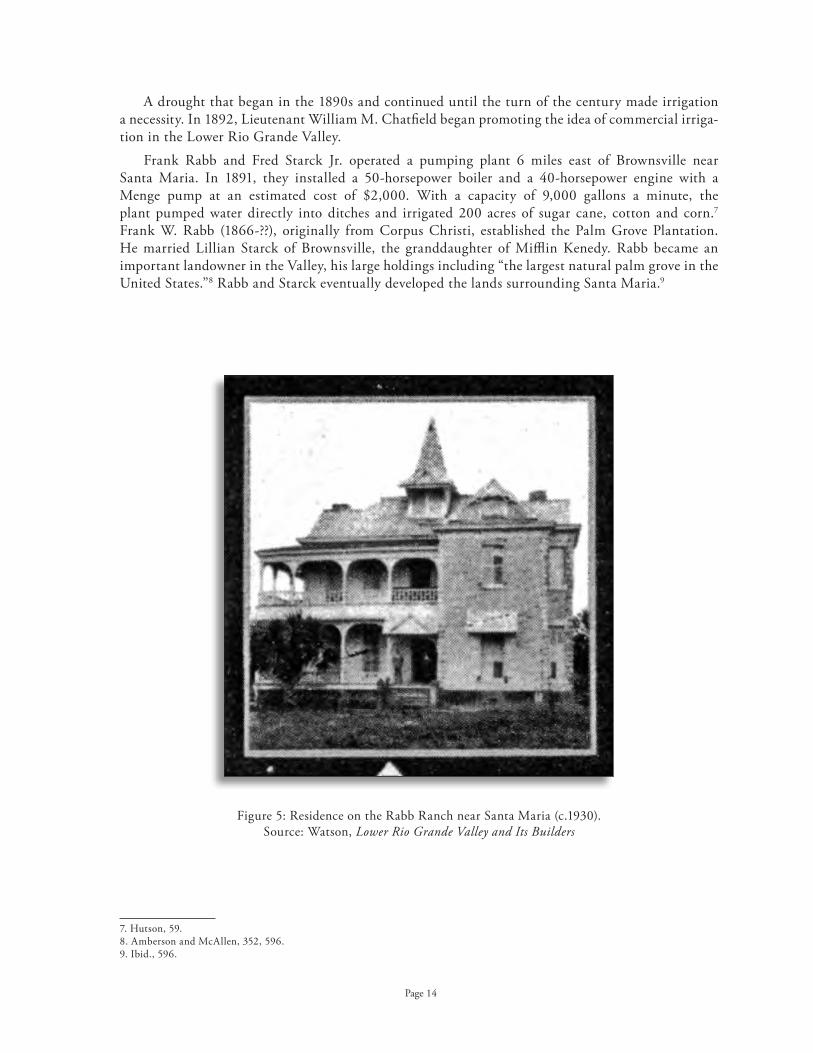
Residence on the Rabb Ranch near Santa Maria (c .1930) . Figure 5: Source: Watson, Lower Rio Grande Valley and Its Builders
Page 14
A drought that began in the 1890s and continued until the turn of the century made irrigation a necessity . In 1892, Lieutenant William M . Chatfield began promoting the idea of commercial irriga-tion in the Lower Rio Grande Valley .
Frank Rabb and Fred Starck Jr . operated a pumping plant 6 miles east of Brownsville near Santa Maria . In 1891, they installed a 50-horsepower boiler and a 40-horsepower engine with a Menge pump at an estimated cost of $2,000 . With a capacity of 9,000 gallons a minute, the plant pumped water directly into ditches and irrigated 200 acres of sugar cane, cotton and corn .7 Frank W . Rabb (1866-??), originally from Corpus Christi, established the Palm Grove Plantation . He married Lillian Starck of Brownsville, the granddaughter of Mifflin Kenedy . Rabb became an important landowner in the Valley, his large holdings including “the largest natural palm grove in the United States .”8 Rabb and Starck eventually developed the lands surrounding Santa Maria .9
7 . Hutson, 59 .8 . Amberson and McAllen, 352, 596 .9 . Ibid ., 596 .
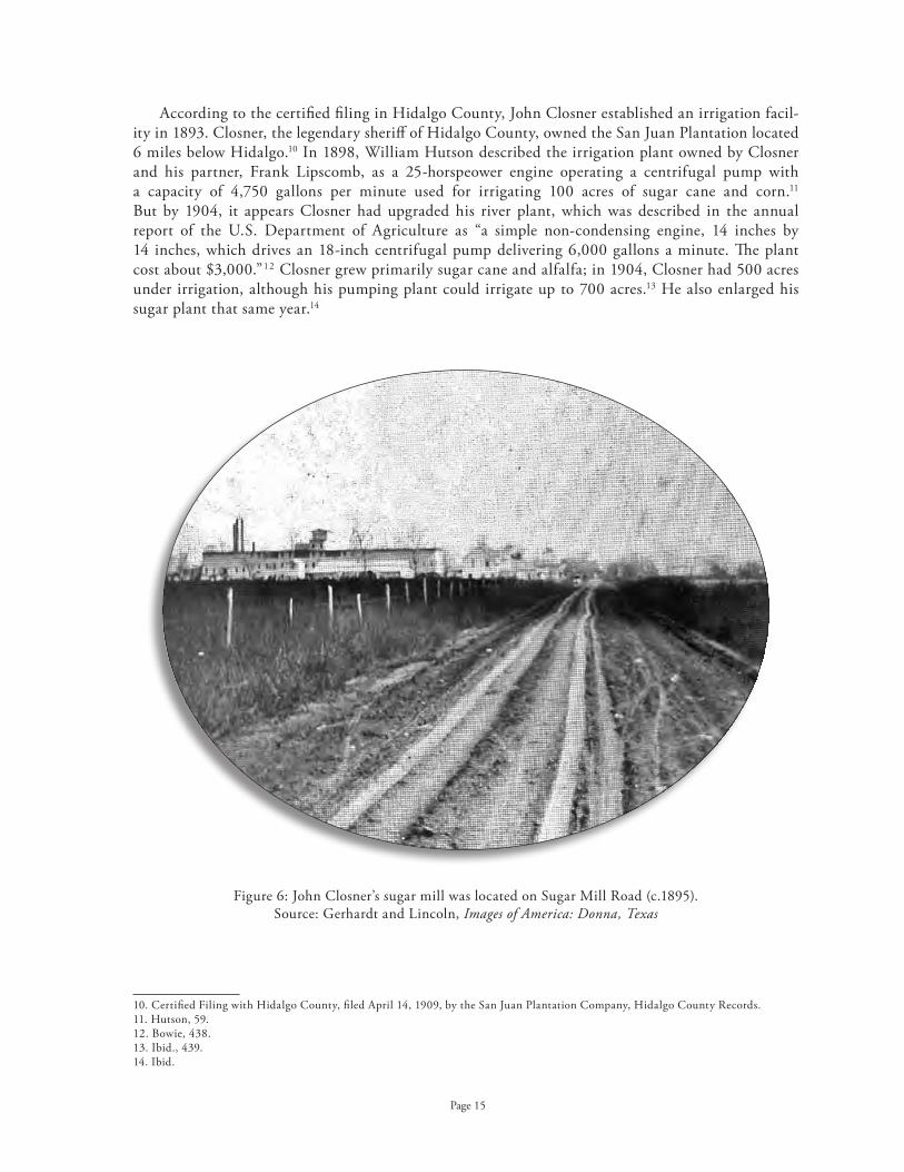
John Closner’s sugar mill was located on Sugar Mill Road (c .1895) .Figure 6: Source: Gerhardt and Lincoln, Images of America: Donna, Texas
Page 15
According to the certified filing in Hidalgo County, John Closner established an irrigation facil-ity in 1893 . Closner, the legendary sheriff of Hidalgo County, owned the San Juan Plantation located 6 miles below Hidalgo .10 In 1898, William Hutson described the irrigation plant owned by Closner and his partner, Frank Lipscomb, as a 25-horspeower engine operating a centrifugal pump with a capacity of 4,750 gallons per minute used for irrigating 100 acres of sugar cane and corn .11 But by 1904, it appears Closner had upgraded his river plant, which was described in the annual report of the U .S . Department of Agriculture as “a simple non-condensing engine, 14 inches by 14 inches, which drives an 18-inch centrifugal pump delivering 6,000 gallons a minute . The plant cost about $3,000 .”12 Closner grew primarily sugar cane and alfalfa; in 1904, Closner had 500 acres under irrigation, although his pumping plant could irrigate up to 700 acres .13 He also enlarged his sugar plant that same year .14
10 . Certified Filing with Hidalgo County, filed April 14, 1909, by the San Juan Plantation Company, Hidalgo County Records .11 . Hutson, 59 .12 . Bowie, 438 .13 . Ibid ., 439 .14 . Ibid .

Page 16
John Closner arrived in Hidalgo County in the summer of 1884 as a stage driver on the Hebbronville to Brownsville route. After serving as a deputy sheriff for Hidalgo County, he was elected county sheriff in 1889.15 Although most sources cite that he bought up thousands of acres of land in Hidalgo County, it is not really known for certain just how much land he owned, for by 1901 Closner was serving as a real estate agent for local landowners in addition to farming his own land.
One of the earliest commercial ventures, albeit unsuccessful, was proposed in 1896 by the Hidalgo and Cameron Irrigation Company, with its' certified filing in Cameron County to irrigate 800,000 acres. The company’s proposed 30-foot wide canal had a capacity of 1,370 feet per second, which was faster than the normal rate of the Rio Grande River. Located near Brownsville, the project was never initiated.16
Other landholders also irrigated their own tracts of lands. In 1897, E.H. Goodrich installed a 10-horsepower Priestman engine on a resaca in Cameron County to pump water for irrigation purposes. He also used windmills for the same purposes, pumping the water into flumes that connected to his ditches. The cost of his facilities was a mere $300.17 J. Box is reported to have had 75 acres under irrigation adjacent to the San Juan Plantation, with plans to irrigate an additional 200 acres. According to sources, he utilized one 12-inch centrifugal pump delivering 4,000 gallons a minute and planted largely corn.18 There were also at least two irrigators on the Mexican side of the border. M.M. Mendiola, an engineer for the Mexican government, irrigated 100 acres of sugar cane near Matamoros. J.H. Fernandes also operated a pumping plant to irrigate 600 acres of rice in the same area.19
15. Amberson and McAllen, 374, 379.16. Bowie, 437.17. Hutson, 59.18. Bowie, 439.19. Ibid., 441-442.

Early pumping plant on Figure 7: the Rio Grande at Brownsville (c .1930) .
Source: Watson, Lower Rio Grande Valley and Its Builders
Page 17
tHE BirtH of CommErCial aGriCulturE in tHE VallEy Early Experiments in Rice and Sugar Cultivation in Cameron and Hidalgo Counties
The earliest experiments with sugar cane in the Valley were small, local enterprises for local markets . It was not until the opening of the Valley through the coming of the railroad that adequate venture capital became available for the development of large modern sugar mills capable of milling sugar on a commercial basis . According to Lon Hill in September of 1902, “The future of that country will be assured by a railroad and it will become a garden spot .”1 Without adequate transportation, commercial agriculture could not develop in the Valley .
Lon Hill, an attorney from Beeville, arrived in the Valley in 1900 . After having soil samples analyzed at Texas A&M to determine what crops would best grow in the area, he purchased acreage on the Rio Grande near Brownsville on what was called the Rincon Farm . Unlike others, however, Hill planted rice, growing as much as 28 bags an acre .2 In a 1902 interview in the San Antonio Express, Hill was credited with being “the first man to advocate irrigation and put it to actual test in that section of the country .” According to the article, Hill and William Ratcliff planted 100 acres of rice in 1901 as an experiment, yielding 15 sacks of rice to the acre . Based on these results, they planted 3,000 acres in 1902 . In addition, they were also planting sugar cane . The two men used a steam traction engine to plow the fields, thus enabling them to put so many acres under cultivation within such a short pe-riod of time . This 18-horsepower engine required two men to handle it, with one additional man to handle its water needs, and it burned one cord of wood per day .3
The Brownsville Land & Irrigation Company was the first company to install a permanent pumping plant facility located about 6 miles above Brownsville . According to a report by the U .S . Department of Agriculture, the other irrigators in the valley feared that the banks of the river would eventually cave in from flooding and wanted to be able to rescue their pumps from the river . With an investment of $300,000, the Brownsville Land & Irrigation Company constructed a brick wall embankment along 150 feet of the river-bank to reinforce it . The facility also rested on a solid foundation . With a permanent pumping facility and without the fear of the need to move the engines, larger engines could be installed . This river pumping plant had one 200-horsepower boiler and one 18 by 42-inch 225-horsepower Corliss condensing engine connected to a 36-inch centrifugal pump . In addition, two boil-ers supplied steam to two non-condensing engines of 125-horsepower connected to two 24-inch centrifugal pumps . The capacity of the plant was 40,000 gallons from the 36-inch pump and 20,000 gallons per minute from each of the 24-inch pumps .4 This far exceeded the 4,000-6,000 gallons per minute that other irrigators were getting from their much smaller pumping plants .
1 . Brownsville Daily Herald, September 10, 1902 .2 . Kate Hill, Lon C. Hill, 1862-1935, 24 .3 . Brownsville Daily Herald, September 10, 1902 .4 . Bowie, 440 .

View of the Rio Grande (c .1930) . Figure 8: Source: Watson, Lower Rio Grande Valley and Its Builders
Page 18
The Brownsville Land & Irrigation Company was also the first large-scale land company in the Valley . Rather than selling land, however, the company was primarily interested in developing large tracts of rice . Thus most of the land was leased to tenants for one-half the value of the crop, with the company supplying all of the necessary water at no cost to the tenant .5 The Brownsville plant irrigated 7,000 acres of rice and 125 acres of vegetables in 1904, the year the railroad arrived in the Valley .6 The main canal was 100 feet wide with a fall of only 6 inches per mile . This very shallow canal allowed for ease in flood irrigation of the rice fields . Moreover, some sections of the canal were dug deeper in places to allow for the canal to also serve as a drainage ditch .7
These initial experiments in rice farming, however, soon failed due to the lack of adequate drainage . Rice farming requires large amounts of water used to flood the land . As a result, if the water is not adequately drained, salts are pulled up and the soil becomes so highly alkaline that it will not sustain crops of any kind . The first large-scale rice fields were along the Rio Grande, and these soils were also the highest in natural alkalinity . After just several years of intensive rice irrigation, these soils became incapable of producing anything . By 1905, Cameron County instituted the first drainage district in an effort to improve the soils of the area . Cameron County Drainage District No . 1 issued bonds for the construction of open drainage ditches that would connect with the few natural drainage systems in the county .
5 . Ibid ., 441 .6 . Ibid .7 . Ibid .

Thomas Hooks standing in one of his cornfields (c .1905) . Figure 9: Source: Gerhardt and Lincoln, Images of America: Donna, Texas
Page 19
Experiments with rice in the earliest years were quickly supplanted by sugar cane in popularity . This was partially due to the rise in soil alkalinity from rice production . However, the subsidy paid by the United States government for domestically produced sugar was also an important contributing factor .
Sometime before 1902, Thomas J . Hooks of southern Louisiana and A .F . Hester from East Texas purchased land in Hidalgo County and installed a pumping plant at Run, located 12 miles below Hidalgo .8 They purchased a total of 25,000 acres at 75¢ to $2 .00 an acre, including the 13,000 acre La Blanca Ranch .9 They initially planted rice, as Hester had raised the crop in Hardin County, but they also had 125 acres of alfalfa, corn and truck vegetables under irrigation .10 In 1902, they established the La Blanca Agricultural Company along with other investors and stock in the amount of $100,000 .11 But Hooks had been a successful sugar cane grower in Louisiana and intended to establish a sugar cane plantation along the Rio Grande . The following year, he created the Arroyo Canal Company .12
8 . Gary Ratkin, “Railroad Reaches Valley Area,” Texas Farming and Citriculture, 8 .9 . Watson, 47 .10 . Bowie, 439 .11 . Watson, 49 .12 . Ibid .

Page 20
John Closner’s San Juan Plantation, located 6 miles downstream of Hidalgo, was not one of the first tracts of land to experiment with the growing of sugar cane, as is often highlighted in local histories . As mentioned previously, George Brulay established his sugar cane operation and sugar mill 30 years before Closner .13 Indeed, his operation may have inspired Closner to undertake such an enterprise in Hidalgo County . Closner did, however, play an important role in its development, especially in its promotion of the Lower Rio Grande Valley on a national basis . Closner apparently first began planting sugarcane in 1895 when he cross-planted hybrid sugar cane seed from Mexico with seed from Louisiana .14 He reportedly harvested 35 to 40 tons of sugarcane per acre, yielding 240 pounds of sugar per acre . His product, however, was only sold locally and in Mexico, in the cone-shaped piloncillo form, as no commercial sugar mills were available . In 1897, Closner established a 250-ton mill on his plantation . He ordered two boilers; one arrived by rail to Laredo where it was shipped to his plantation by barge . When the barge struck some rocks, the boiler had to be floated down the river . The second boiler was shipped to Hebbronville and then “rolled” overland by a team of horses to the site .15 Sources claim that in 1906, Closner was producing 650,000 pounds of sugar at his mill .16
In 1902, Closner and William Briggs organized the Hidalgo Canal Company after purchasing 9,500 acres north and east of Hidalgo . This tract of land measured some 1 .12 miles wide at the river and extended approximately 15 miles to the north .17 The Hidalgo Canal Company established a pumping plant above Hidalgo to irrigate an initial 300 acres . The small plant, located directly on the river, con-sisted of two 50-horsepower centrifugal engines and two boilers . These facilities were placed directly on the banks of the river without a building, “in anticipation of the necessity of moving it, due to caving of the river bank .”18 The description of the canals is typical of the early construction of such systems, leading to the need for considerable reconstruction at a later date .
“The main canal was 50 feet wide and very shallow with small banks . Its grade is 3 .5 feet for the first mile, and its total length is 4 miles . The company has also one lateral canal 50 feet wide and another 25 feet wide, each 1 mile long . Some of the lateral canals are 6 feet wide and run in the direction of greatest slope . . . the banks of the canals were poorly constructed and are subject to considerable leakage .”19
The very steep grade for the first mile would have caused considerable erosion of the canal over time . Also, the shallowness of the canal would have made it difficult to convey water over any great area . The short length of this particular canal, only four miles, was sufficient for the limited acreage of the endeavor . Unlike later projects, this company leased land to tenants who grew principally alfalfa, with the Hidalgo Canal Company receiving two-fifths of the crop .20
13 . Ratkin, 9 .14 . “Story of San Juan Plantation,” 1965 .15 . Ibid .16 . Ratkin, 9 .17 . “Hidalgo Canal Company,” 1907 .18 . Bowie, 438-439 .19 . Ibid ., 439 .20 . Ibid ., 438 .

Page 21
BEnjamin yoakum’s Vision for tHE VallEy The Arrival of the Railroad in the Lower Rio Grande Valley
Local histories unanimously give John Closner full responsibility for bringing investors to the Valley, as a result of his winning the Gold Medal for sugar cane in 1904 at the World’s Fair held in St . Louis . Yet, there is more to this simple story of a small-town sheriff beating out the experienced sugar cane growers from Louisiana, Hawaii, and even Cuba and the Caribbean . It begins with a rail-road magnate’s vision for the future agricultural development of the Valley and his ambitions to build a railroad that would reach all the way to Mexico City .
Although Uriah Lott is often credited with bringing the railroad to south Texas, Benjamin F . Yoakum is the man responsible . Yoakum found his way into the railroad business, however, through Lott . Yoakum was working for Jay Gould’s International & Great Northern Railroad as a passenger agent, finding immigrants from Europe to relocate along the railroad lands . Lott hired him as his new chief clerk for the newly established San Antonio & Aransas Pass Railroad (SAP) .1 Although Lott went broke, Yoakum would become one of the largest railroad magnates of the twentieth century .
Yoakum became head of three major railroad systems: The Frisco (also known as the St . Louis & San Francisco Railroad); the Rock Island Railroad (which ran from Kansas City to Fort Worth); and the Gulf Coast Lines . Yet it was the Gulf Coast Lines that fulfilled his dream of wresting control of the region from Louisiana and Texas away from the Southern Pacific .2 This line would run from Memphis to Mexico City via New Orleans, Houston and Brownsville . His dream ultimately collapsed in 1913, when the Frisco went into receivership . He eventually lost all of his railroads, but retired a very wealthy man in New York State .
Yoakum’s experience as a “land boomer” for Jay Gould in the 1880s made him aware of the opportunities in the Valley . “He believed the [rail] road would attract additional home seekers to settle on the land, establish new towns and lure the coming of industries, thereby providing more and more tonnage for such roads .”3 Moreover, he wanted to extend the line into Mexico and perhaps eventually to Panama . In a 1929 interview with the Corpus Christi Times, Yoakum would recall “how awed he was with the Rio Grande when he had seen it years before [in the 1880s] . ‘What I discovered was a revelation to me, I could see but one future, although requiring years for development, for such a rich and productive country which needed only transportation to give it access to the balance of the commercial world .’ ” 4
In March of 1903, Yoakum succeeded in getting the State of Texas to approve the consolidation of six small Texas branch lines as the St . Louis, San Francisco & Texas Railway Company (which later became the Red River, Texas & Southern Railway Company) .5 But to get to South Texas, Yoakum’s line would have to cross the King Ranch . Robert Kleberg and Major John Armstrong had been holding out hopes of building a railroad to South Texas for years . Attempts at building such a railroad had been stalled numerous times, either for lack of funding or for fear of interfering with the steam-ship monopoly of the King family . A series of letters between Yoakum and Kleberg in the summer of 1902 make it clear that they were in close communication with one another about the prospect of such a an enterprise .6
1 . James Krug, “Benjamine Franklin Yoakum and the St . Louis, Brownsville & Mexico Railroad,” 1 .2 . Ibid ., 2 .3 . Ibid ., 17 .4 . Ibid ., 22 .5 . Ibid ., 7-8 .6 . Ibid ., 19-20 .

First pumping plant for the American Rio Grande Land & Irrigation Company (c .1930) . Figure 10: Source: Watson, Lower Rio Grande Valley and Its Builders
Page 22
According to the memoirs of Kleberg, he met with Yoakum and a large group of investors in St . Louis in late 1902 .7 The St . Louis Union Trust Company and its officers put up $800,000 in bonds . In return, the large ranchers in the northern part of the Valley – King, Kenedy, Armstrong, Yturria, and others – would donate land to the enterprise through the formation of land companies for the establishment of towns that would then donate half the stock to the St . Louis syndicate . In Brownsville, the group asked for the donation of 12,000 acres within 4 miles of the railroad and 60 acres within the city limits for a depot and shops, in addition to a $40,000 cash bonus .8
Kleberg agreed to undertake organization of the company under Texas laws and begin a survey . Yoakum suggested Lott, as president of the company, should supervise construction of the line .9 Kleberg served as vice-president and treasurer and Kenedy served as secretary . Other incorporators in Texas included: Robert Driscoll Sr ., Robert Driscoll Jr ., J .B . Armstrong, Arthur Spohn, E .H . Caldwell, George Evans, Francisco Yturria, Thomas Carson, and Caesar Kleberg . Benjamin F . Yoakum’s syn-dicate of investors included: T .W . Carter, T .H . West, Edwards Whittaker, Sam Fordyce, E .E . Elliot, DuVal West, and S .P . Silver . These same investors would form the American Land and Irrigation Company in 1905 . Their Capisallo Land and Development Company purchased land to organize the townsite of Mercedes, named after Mexican President Diaz’s wife . Jim Wells, the chairman of the State Democratic Committee and the political boss of south Texas, served as general counsel and as a board member for the railroad, as he handled all the complicated issues regarding the acquisition of land titles in the Valley .10
Thus, Benjamin Yoakum was investing heavily in land in the Valley before construction began on his railroad . In 1903, Yoakum purchased 39,000 acres in Hidalgo County and Thomas Carter, a St . Louis grain merchant and member of the St . Louis railroad syndicate, also purchased a large tract of land . They continued to purchase large tracts over the next year and in August of 1903, only one month after actual construction on the railroad began, the two men chartered the American Rio Grande Land and Irrigation Company . This would become the largest and most successful irriga-tion company in the Lower Rio Grande Valley, with land holdings of 104,000 acres .
7 . Ibid ., 21 .8 . Ibid ., 25-26 .9 . Ibid ., 21 .10 . Milo Kearney and Anthony Knopp, Boom and Bust, 200-205 .

Map of the St . Louis, Figure 11: Brownsville & Mexico Railroad (1904) . Source: Harding and Lee, Rails to the Rio
Page 23
The Johnston Brothers Construction of Illinois received the construction contract for the railroad and subcontracted with Sam Robertson’s Southern Contracting Company for the laying of the track . Yellow fever, the lack of adequate supplies, flooding, Robertson’s financial problems and inexperience – all combined to delay construction . But on July 4, 1904, the train finally arrived in Brownsville on time . The big celebration, however, was reserved for the new town of Kingsville, taking place there on the same day . As the train construction headed south, numerous new towns were created as stops along the line, including: Robstown, Bishop, Sarita, Mifflin, Armstrong, Norias, Rudolph, Raymondsville, Lyford, Sebastian, Harlingen, San Benito, and Olmito . As many of these towns were named after the men who donated a portion of their ranch lands to secure the railroad, this long list is an indication of the importance the ranchers of the upper Valley played in bringing the railroad to the area . The importance to Brownsville, however, did not go unnoticed . Yoakum received a tele-gram that thanked him “for giving us our independence by the completion of the Lott Road, which connects us with the outside world . In honor of the advent of the railroad the citizens Council will tomorrow change Brownsville time from sun to standard .”11
11 . Krug, 34-45 .

Page 24
Yoakum’s background as a land promoter for Jay Gould served him well . He understood the need for a publicity campaign to make people aware of this isolated corner of the United States . As an influential resident of St . Louis, he was in a position to wield some influence at the World’s Fair . He may have encouraged Closner to submit the sugar cane to the Fair, and perhaps inspired others as well, for Lon Hill submitted the first bale of cotton . Yoakum’s knack for winning awards for others at expositions was noted previously when he worked for the San Antonio & Aransas Pass Railroad . One such incidence is noted prominently in an obituary, noting that he had been in charge of an exhibit of fresh fruit from Texas at the 1895 Cotton States and Industrial Exposition in Atlanta . When the shipments of fruit from Texas reached him each day spoiled, he decided:
“ . . . that Texas-grown fruit was the best in the world and that his state should be represented in the next best way . . . By paying the fruit dealers a bonus for the privi-lege, he selected the finest California fruit on the Atlanta market . The Texas exhibit of fruits quickly became the talk of the entire Southeast . When ribbed about it later, he justified his little deception with the claim that the best of fruit from anywhere else was only second best when compared with that grown in Texas .”12
12 . “Rail Empire Dream Came in Ox Wagon,” by J . Edward Morrow, obituary, undated clipping in file, University of Texas Center for American History .

Map of Cameron Figure 12: County Water Improvement District No . 6 illustrating subdivisions (1922) . Source: Files of Cameron County ID No . 6, Los Fresnos
Page 25
EstaBlisHmEnt of priVatE irriGation CompaniEs
The arrival of the railroad secured the economic potential of the full-scale development of the Valley . According to a 1904 publication of the U .S . Department of Agriculture, land prices increased to $15 to $20 an acre along the lower Rio Grande with the arrival of the railroad and the “possibilities of irrigation .”1 Private investors rushed to participate in a new land development that could possibly become as profitable as similar schemes in California, Florida, and Utah . Investors formed private companies or corporations that purchased, or took options to purchase, large tracts of land, varying in size from 1,000 acres to over 100,000 acres . The topography of the country and the Spanish porciones system is reflected in the shape of these tracts that began at the Rio Grande and stretched back from the river anywhere from 3 to 30 miles . Access to the river was essential for both the construction of a pumping plant and for the claim to water rights .
The irrigation companies and the land companies were typically separate entities, although it was not uncommon for the same men to serve as directors in each organization . There were some excep-tions of companies that served both purposes of providing land and water . The American-Rio Grande Land & Irrigation Company both sold land and developed an irrigation system . The land tracts were divided into subdivisions consisting of hundreds or thousands of acres and either sold outright to land companies or retained and sold on a commission basis through land companies . These subdivisions were further subdivided into smaller tracts of 10, 40, 60, 80 or 150-acre tracts to the block, to sell to individual property owners .
1 . Bowie, 351 .

Group of potential buyers inspecting the canals Figure 13: of the Louisiana-Rio Grande Canal Company (1910) . Source: Texas Historical Commission Marker Files
Page 26
Many of the local political leaders served as land agents, linking the outside investors with local landowners . By 1901, John Closner was serving as a real estate agent for local landowners, in addition to farming his own land at San Juan Plantation . Along with James B . Wells, he served as agent in the J .L . Withers purchase of over 13,000 acres in the Llano Grande in 1902 . According to Wells, he “had his doubts about Closner’s skill with land speculators because he was slow to act, while others like Lon C . Hill and Thaddeus Rhodes tried to sell to Withers .”2
Special excursion trains from the Midwest brought potential buyers of land, primarily Midwestern farmers, to the Valley to purchase the newly irrigated lands . Land companies established model farms to dazzle the potential buyers with the lush potential of the fertile lands of the delta . Buyers would be met at train stations with a caravan of automobiles and the potential investors would be carefully monitored so agents from another real estate company would not steal them . Clubhouses had to be constructed to house the visitors, as the Valley had no such infrastructure for an onslaught of over-night visitors . Buyers would be entertained with visits to Mexico and special activities for the wives . Even William Jennings Bryan, the ever-popular celebrity of the day, was offered a home in the Valley near Mission in exchange for his entertainment services . Texas, however, was not the only place where Bryan “settled .” In 1925, he accepted $100,000 and property from George Merrick of Coral Gables .
“To tout his [Merrick’s] new development, Bryan spoke for an hour each day while sitting under an umbrella and wearing a big white Panama hat . After he finished, an orchestra and shimmy dancer entertained the potential customers . He [Bryan] predicted Miami would blossom into a great place for the middle-class who would welcome their neighbors from the South .”3
2 . Amberson, 602 .3 . Michael Kazin, A Godly Hero, 265-266 .

Clubhouse for the Delta Orchards Company, Raymondville (c .1930) . Figure 14: Source: Watson, Lower Rio Grande Valley and Its Builders
Clubhouse for the McLoud Hood Company, Rio Hondo (c .1930) .Figure 15: Source: Watson, Lower Rio Grande Valley and Its Builders
Page 27

Map of Cameron County Figure 16: Water Improvement District No . 2 (revised to March, 1918) .
Source: Cameron County Irrigation District No . 2, San Benito
Page 28
While the selling of small farm plots was an important enterprise, many of the early land com-panies were interested in establishing large farms or plantations for investment purposes . Smaller lots were sold merely to recoup some of the initial investment costs of installing the irrigation system and to recover land costs . For example, the American-Rio Grande Land & Irrigation Company operated a 3,000 acre sugar cane plantation and constructed a sugar mill . By 1911, this operation had expanded to 8,000 acres .4
Without irrigation, however, the land was worthless . Under the 1889 irrigation law of Texas (revised 1895), irrigation or land companies established their prior water rights through a “declaration of intent” filed with the county clerk . This filing included a description of the location of diversion, the number of acres to be irrigated, the capacity of the main canal, and a map . The company often inflated the number of acres they claimed to be irrigating far beyond the number of acres actually owned or even secured under option . This eventu-ally led to an over-appropriation of the waters of the Rio Grande that would not be settled until the adjudication of water rights in 1967 . Further, not all of the canal companies even bothered to make certi-fied filings before beginning the construction of their irrigation systems, relying instead on the riparian water rights of the land they purchased . The Santa Maria Irrigation Company began construction in 1905 but did not make a certified filing until required to do so under a new state law in 1914 .
Ratcliff, Johnson and others made the first cer-tified filing in Cameron County on April 2, 1902 . These same men re-filed on May 1, 1902 under the name of the Brownsville Land & Irrigation Company for 196,000 acres of land . The San Benito Land and Water Company made the second filing in Cameron County on June 10, 1914 .5 This was the first certified filing that did not overstate its acreage, but instead filed only for the tract of land under its ownership .6 The first filing in Hidalgo County was not made until three years after the first filing in Cameron County, when W .T . Adams filed for a tract of land in 1905 . The following year, on July 30, the American-Rio Grande Land & Irrigation Company made a certified filing to irrigate 250,000 acres .7
4 . Krug, 62 .5 . Cameron County Water Improvement District No . 2 files, State Board of Water Engineers, Texas State Library and Archives .6 . Frank Robertson, “History of Irrigation in the Valley,” 1937 .7 . Ibid .

Office of the Hidalgo Canal Company, 1907 . Figure 17: Source: “Hidalgo Canal Company,” Hidalgo Advance,
Special Irrigation Edition, November 1907
Page 29
An irrigation system was installed as quickly as possible to provide water to the new farms . Beginning with a pumping plant at the river operated by steam engines, large pumps “lifted” water from the river into a large earthen main canal that extended northward . Most of the main canals extended along the western edge of the irrigated lands as the natural topography drained toward the northeast . Some irrigation systems also included a high line main canal that irrigated lands lying parallel to the river . Laterals extending off the main canal were constructed as necessary to farmland as it was sold . Land was sold to farmers in scattered tracts wherever they wanted to buy it, leading to inefficiency in the overall design and function of the irrigation system .
It took several years to construct the irrigation systems necessary to water the lands . Thus it was not until about 1910 that the true impacts of these efforts began to take effect . It generally took one to two years to construct the irrigation system, although in actuality most systems took much longer to construct . Much of this effort was devoted to obtaining the necessary financing . A river pump-ing plant alone cost an average of $40,000 to $70,000 to construct and was a necessary first step to obtaining water for the system . The construction of a canal system typically cost companies from $85,000 to $225,000 to construct, depending upon its length and the amount of acreage covered by laterals .8 In 1902, there were only four irrigation companies in existence: The Rio Grande Canal Company, the Brownsville Land & Irrigation Company, the Hidalgo Canal Company, and the La Gloria Canal Company (the Hidalgo Company had already failed) . Two years after the arrival of the railroad, there were a total of nine irrigation companies working to install or complete irrigation systems (the additional five companies were: Arroyo Canal Company, San Benito Land & Irrigation Company, W . T . Adams, Louisiana–Rio Grande Canal Company, and the American-Rio Grande Land & Irrigation Company) . By 1910, there were at least 20 such irrigation companies along the Rio Grande River in Cameron and Hidalgo counties . The extension and completion of the irrigation systems continued up to the beginnings of World War I .9
By 1907, the Hidalgo Canal Company completed 6 miles of main canal, 75 feet in width, and reported that all of the land north of the river for 4 miles had been sold in their 9,500 acre tract . This represented, however, only 20 differ-ent parties purchasing the land .10 Although a private company, they claimed in a 1908 advertisement that “each landowner owns his pro rata share of the irrigat-ing plant and canal and has a voice and vote in manage-ment through ‘co-operative water stock’ .”11
8 . James Nagle, Irrigation in Texas, 51-55 .9 . Robertson, 1937 .10 . “Hidalgo Canal Company,”1907 .11 . Advertisement for Hidalgo Canal Company, Irrigation Scrapbook, Museum of South Texas History, Edinburg .

Page 30
Irrigation companies supplied water to farmers and tenants under contract . The cost of water varied from company to company . Some irrigation companies charged by the acre . Under this type of contract, a farmer could irrigate as often as he wanted . Other contracts charged a flat rate of $3 to $4 per acre annually with each acre irrigated charged a minimal cost of $1 per acre above the flat rate . In yet other cases, irrigation companies charged farmers by the acre based on the type of crop grown . These various methods of charging costs often led to the financial difficulties of the irrigation companies . As the water was not carefully monitored and measured, it was impossible to adequately judge how much water was delivered to each farmer . Yet the pumping costs, particularly in regard to energy, maintenance and construction costs, were not always covered by water charges . There were occasions when water was not supplied to some farmers because of drought (when water levels were too low to be pumped) or because of pumps breaking down . The loss of a single season of irrigation could break a small farmer, leading to the loss of his land . Once a majority of the land within an irrigation company’s area was sold, or if land sales slowed considerably, there was little incentive to continue to properly maintain or extend the irrigation system . Maintenance costs for a pumping plant averaged $10,000 annually .12
Towns were located generally 11/2 to 3 miles apart . Transportation was key to the survival of this new endeavor . Most vegetables were highly perishable and needed to be shipped to markets as soon as possible . Loading them on wagons and carting them long distances along bumpy roads only fur-ther bruised the fragile commodities . The railroad invited the land development companies to donate acreage for depots and railway right-of-way for the spur of the St . Louis, Brownsville & Mexican Railroad branch that extended west into Hidalgo County . The companies gladly acquiesced in exchange for the development of a town with a depot stop in the middle of their land development . Town improvement companies were formed to pay the expenses of surveying, clearing the land, installing the basest of infrastructure, and constructing the depot . When developers were unable to pay these expenses, the railroad offered to pay the costs in exchange for town lots . The St . Louis, Brownsville & Mexican Railroad made such an exchange in the town of McAllen, when the land company failed to raise the necessary funds for development and construction of the railroad depot
12 . Nagle, 52 .

Page 31
1896 Hidalgo Company Failed
1902 1902 Brownsville Land & Irrigation Company Cameron 6 1922
1902 Brownsville Irrigation Company
1902 Rio Grande Canal Company Cameron 6 1922
1902 Hidalgo Canal Company Hidalgo 3 1921
1903 1906 (completed)
American-Rio Grande Land & Irrigation Company Hidalgo 9 1927
1903 Arroyo Canal Company Donna/Hidalgo 1 1914
1904 or 1905 Santa Maria Canal Company
1904 Tijon Water Company
1904 San Benito Land & Irrigation Company Cameron 2 1916
1905 W .T . Adams Hidalgo 5 1925
1906 1908 Louisiana-Rio Grande Canal Company (includes San Juan Plantation) Hidalgo 2 1920
1907 1907 San Benito Land & Water Company Cameron 2 1916
1907 1908 Valley Reservoir & Canal Company Hidalgo 1 1926
1907 1907 Mission Canal Company Hidalgo 7 1927
1908 1907 Harlingen Land & Water Company Cameron 1 1914
1908 1908 Indiana Cooperative Canal Company Cameron 5 1919
1908 1902 and 1907 La Donna Canal Company Donna/
Hidalgo 1 1914
Date Established
Canals Begun Irrigation Company Irrigation
DistrictDistrict
Established
eArly irrigAtion compAnies in the lower rio grAnde vAlley

Page 32
1908 Del Monte Irrigation Company Hidalgo 6 WCID 1927
1907 or 1908 La Gloria Canal Company Failed
1908 1908 Rio Bravo Canal Company Failed
1909 1908 La Feria Mutual Canal Company Cameron 3 1917
1909 1908 West Brownsville Canal Company Cameron 7 1927
1909 Hidalgo Irrigation Company Hidalgo 3 1921
1910 W .T . Adams Canal & Irrigation System Cameron 19 1931
1914 Santa Maria Irrigation Company Cameron 4 1918
1914 Rio Grande Mission Land Improvement Company Hidalgo 7 1927
1915 United Irrigation Company Hidalgo 7 1927
1917 Borderland Sugar Hidalgo 5 1925
1918 Mutual Irrigation Company Hidalgo 3 1921
1919 Edinburg Canal Company Hidalgo 1 1926
1926 Goodwin Corporation Hidalgo 6 WCID 1927
1927 Rice Tract Cameron 16 1930
1927 Mestenas Water Company Hidalgo 6 WID 1929
1951 Rio Grande Palms Water District Cameron 20 1951
Date Established
Canals Begun Irrigation Company Irrigation
DistrictDistrict
Established
Early irrigation companies, contd.

Typical early housing for Mexican workers . Figure 18: Source: Gerhardt and Tamez, Weslaco
Page 33
Early aGriCultural dEVElopmEnt of tHE lowEr rio GrandE VallEy The Rise of the Sugar Cane Industry in South Texas
Sugar cane attracted major investors to the Valley during its first decade of development . Few areas in the United States were capable of sustaining sugar cane, which required a fertile, yet well-drained soil, a semi-tropical climate, and a large supply of water . The largest producers of sugar were Louisiana, Hawaii, Cuba and Puerto Rico . Louisiana long held the title as the only significant producer of sugar cane in the United States, but the Lower Rio Grande Valley sought to overtake her title . Located farther south than Louisiana, the Valley boasted a longer growing sea-son . This afforded the sugar cane a longer time to ripen and produce more sugar before harvesting, resulting in more tons per acre and a higher yield of sugar per ton . Whereas in Louisiana, the cane would have to be cut and replanted every three years, cane plants could last six years in the Valley . Moreover, it could be harvested anytime between November and February . Mechanization of sugar cane harvesting was not yet possible, so manual labor was essential to its successful production . The Valley offered a reliable source of cheap labor in its Mexican citizens .1 In 1912, the Hawaiian Stock Exchange reported a 12% return in dividends in all of its sugar companies .2 The prospect of the lucrative sugar cane industry was very attractive to many of the early investors in the Valley, including Benjamin F . Yoakum and his syndicate, as well as others .
1 . “America’s Greatest Sugar Country .”2 . Ibid .

Little evidence survives to document the lives of Mexican Figure 19: workers from the early twentieth century (c .1912) .
Source: Gerhardt and Tamez, Images of America: Weslaco
Page 34
A frantic land boom ensued as large-scale investors descended on the Lower Rio Grande Valley to take advantage of high sugar prices . Closner sold the San Juan Plantation in 1910, reportedly for $250,000, to a group of sugar beet growers from Ft . Collins, Colorado .3 Yet, he had already begun selling part of the property as early as 1907 and by 1909, Closner was $300,000 in debt and his ventures in land projects had ended in receivership .4 His involvement in the Hidalgo Canal Company (with Briggs) and the Valley Reservoir and Canal Company (with William Sprague and others) had over-extended his financial ability, even as Sheriff of Hidalgo County .
Lon Hill bought large tracts of land further north around Harlingen and began growing cotton until the installation of an irrigation system could sustain the cultivation of sugar cane . In 1908, he established the Harlingen Land & Water Company to develop an irrigation system, establish a town, and develop the surrounding lands for agricultural production . He also established a sugar mill adjacent to the railroad line . Hill continued to purchase large tracts of land that he later sold to the American Rio Grande Land & Irrigation Company and the Hidalgo Irrigation Company, probably to raise capital for his own venture . P .E . Blalack bought land from Hill to develop a sugar planta-tion, the Buena Vista Plantation . He requested an analysis of his sugarcane from the Louisiana Sugar Experiment Station that reported his sugar was 86 .57% pure (with 17 .17% sucrose) in contrast to 85 .29% (with 17% sucrose) for Cuban sugar and 78 .4% (with 13 .1% sucrose) for Louisiana sugar . Blalack reported a yield of 50 tons per acre . His success attracted Ohio entrepreneurs and resulted in the organization of the Ohio & Texas Sugar Company .5
3 . “Story of San Juan Plantation,” 1965 .4 . Ratkin .5 . Ibid .

Sugar mill near Brownsville (demolished) . Figure 20: Source: Watson, Lower Rio Grande Valley and Its Builders
Page 35
In May of 1911, a group of growers in Cameron County organized the San Benito Sugar Manufacturing Company to establish a sugar factory . Under the leadership of Sam Robertson, bonds were sold to finance the construction of a mill .6 An engineer from New Orleans was hired to build a 1,000-ton daily capacity mill that opened in February of 1912 . Until its opening, the planters leased the 500-ton plant of the Ohio & Texas Sugar Company near Brownsville . The plant was sold to “a syndicate of Eastern capitalists, whose names are synonymous with power along Wall Street, for half a million dollars .” 7 These entrepreneurs made improvements to the plant to increase its capacity to 1,500 tons and invested in a large amount of acreage for the planting of sugar cane in 1913 .8 In addition, the San Benito Sugar Manufacturing Company established a small experiment station, hiring C .L . Wagner to investigate the prospect of growing varieties of cane from other countries . He also brought a demonstration of a steam cable plow from England to demonstrate the benefits of deeper plowing . Wagner had served as the manager of a large plantation in Puerto Rico . Area growers also worked with Congressman Garner and their Senators to obtain a U .S . Department of Agriculture experimental station in the area .9
By 1913, the San Benito district planted over 2,000 acres in sugar cane that yielded 25 tons per acre . The mill paid the grower for the cane (at 90 cents a ton in 1913), with planters grossing $90 an acre . Several large planters in the area invested heavily in the future of sugar cane . As of 1913, S .C . Cowgill owned 1,200 acres with 500 acres under cultivation in sugar cane; H .O . Barber and Sons had 1,000 acres with 300 acres in sugar cane; the Espiritu Plantation had 1,000 acres with 400 acres in sugar cane; and James Landrum purchased the 2,000 acre Cyprus Plantation to be developed for sugar cane . The San Benito Sugar Company Plantation owned a 2,000-acre tract with 500 acres in sugar cane .
6 . Ibid .7 . “America’s Greatest Sugar Country .”8 . Ibid .9 . Ibid .

Ox-drawn carts were used to haul sugar cane to nearby mills (1915) . Figure 21: Source: Gerhardt and Lincoln, Images of America: Donna, Texas
Rail cars hauled sugar cane over longer distances Figure 22: whenever possible, due to the dense weight of the cane .
Source: Gerhardt and Lincoln, Images of America: Donna, Texas
Page 36

Plan of locks on the San Benito Land & Water Company irrigation system (1907) . Figure 23: Source: San Benito Land & Water Company, San Benito in the Lower Rio Grande Valley, 1910
Photograph Figure 24: of lock on the irrigation system (c .1910) . Source: San Benito Land & Water Company, San Benito in the Lower Rio Grande Valley, 1910
Page 37
Due to the excessive weight of sugar cane, averaging 25 tons to an acre, being able to transport it to a processing mill is of critical importance . The San Benito Land & Water Company constructed a transportation network as an important feature of their development project . The canal system itself, with the main canal running along a network of extremely wide resacas and controlled by locks, allowed for large barges to transport cane along the irrigation canal . In addition, the company constructed a road system that served each “plantation size” tract with a spur .10
In 1908, the Minnesota-Texas Land & Irrigation Company constructed an irrigation system on a tract of 10,000 acres south of La Feria for the purpose of developing a large sugar cane plantation . When sugar cane prices failed, they divided up the land into smaller tracts and sold to individual landholders .11
10 . Ibid .11 . Matthews, 61 .

Typical tenant farm home, Hidalgo County (c .1935) . Figure 25: Source: Russell Lee Photographic Collection, 1939
Page 38
tHE small farmEr in tHE VallEy
In 1914-1915, Rex Willard of the U .S . Department of Agriculture visited several hundred farms in the Valley to obtain data for a study on “The Status of Farming in the Lower Rio Grande Irrigated District of Texas .” He visited primarily truck farms, stock farms and staple crop farms . His findings capture a vivid portrait of the first decade of development of agriculture in the Valley . It was Willard’s conclusion that “a farm of less than 40 acres was not large enough in general for any type of farm,”1 thus setting the standard 40 acre subdivision lot . He found the average investment for 59 acres was approximately $14,000: $10,000 for land, $800 for a house, $400 for outbuildings, $1,400 for stock and equipment, and $350 for cash for expenses . The average price of land was $184 per acre for truck farms and $130 an acre for staple crop farms .2 But prices could vary considerably anywhere from $100 to $300 per acre for raw land .3 In contrast, land not on an irrigation system sold for only $40 to $75 per acre .4
During this early period, farmers bought uncleared land and contracted with Mexican laborers for $5 to $25 an acre to clear it . Farms were responsible for the cost of constructing laterals on their land, as well as annual ditch maintenance .5 Double cropping – the growing of more than one crop per year on the same land – was essential to turning a profit . Average farm income was $1471, with truck crops returning 8 .7% and staple crops 3 .9% on initial investment . But Willard found that while truck crops were more profitable, they were also more volatile due to the unpredictability of the market at harvest time .6 The leading staple crops were corn, alfalfa, sorghum, beets, oats, and cotton .
With respect to citrus, Willard found that “the production of oranges and grapefruit has been the basis of much advertising for the region . A very good quality of fruit is produced when the various difficulties of production are overcome, but no growers were found who had made a financial success of these enterprises . Among the difficulties encountered are loss of stock from freezing, disease, insect injuries, and lack of knowl-edge of methods of handling an enterprise so delicate and varied requirements .” 7
Willard also found that many farmers rented their land . Tenants either paid a share of the crop to the land-owner or paid a cash rental of $3 to $10 per acre; $7 per acre was the average .8 Sugar cane was grown only on large farms or plantations, as it re-quired a great deal of water, power, and equipment .
1 . Rex Willard, The Status of Farming in the Lower Rio Grande Irrigated District of Texas, 4 .2 . Ibid .3 . Ibid ., 21 .4 . Ibid .5 . Ibid ., 4-5 .6 . Ibid ., 7 .7 . Ibid ., 9 .8 . Ibid ., 21 .

Loading watermelons onto railroad cars directly from wagons in Raymondville (1914) . Figure 26: Source: Harding and Lee, Rails to the Rio
Page 39
Surprisingly, there were no real local markets for the produce raised by the farmers of the Valley . Brownsville was the largest local city in 1914, with a population of only 10,000 . The closest big markets were Houston and San Antonio . The best markets for the Valley were the cities of the Midwest and most of the perishable produce was shipped to Kansas City, St . Louis, Omaha, Chicago and St . Paul .9 Transportation was still primitive, however . The lack of icing facilities or refriger-ated railroad cars resulted in a great deal of produce loss due to spoilage before it reached market . Few statistics are available from the earliest years on the volume of produce shipped from the Lower Rio Grande Valley, but in the years 1907-1908, 761 railroad cars were shipped to market . By the 1915-1916 season, this increased slightly to 1,064 cars .10
9 . Ibid ., 23 . 10 . Glenn Harding and Cindy Lee, Rails to the Rio, 21 .

Installing a new pump at unknown river pumping plant (c .1930) .Figure 27: Source: Watson, Lower Rio Grande Valley and Its Builders
Page 40
tHE turBulEnt BirtH of irriGation distriCts in tHE lowEr rio GrandE VallEy
By the late 1910s and early 1920s, a number of complex and intertwined factors led to the need to form publicly owned and operated irrigation districts . The river, money, land, politics, war, and the national economy brought about a series of uncontrollable events that led to the end of the first wave of entrepreneurs to the Valley .
Hard Times for Irrigation and Land Companies
The operational costs of the irrigation systems became more than the privately operated irrigation companies could bear . Terms of the early water contracts were made to be as attractive as possible to encourage the purchase of land . But once purchased, the irrigation companies were responsible for continuing to provide these services to the farmers . While the water was essentially free, the maintenance costs of these systems were very high . As few of the early systems had adequate settling basins to remove the heavy silts from the Rio Grande River, each year the earthen main canals and laterals had to be dredged to keep the water freely running within the gravity system . The cost of fuel for running the pumping plants during the irrigation season could be prohibitive, particularly after the surrounding land became cleared and wood became more scarce . The boilers, engines, and pumps required constant maintenance and repairs, and replacement costs were high . Flooding in the Valley caused extensive damage to the irrigation systems . Some irrigation companies, such as the La Gloria Canal Company, literally disappeared; their pumping plants sank into the Rio Grande River as the riverbanks caved in following the disastrous flood of 1909 .1
1 . Frank Robertson, “Water District Story .”

Page 41
Many of the irrigation and land companies were sorely under-capitalized . The financial panic that swept the country in 1907 and 1908 delayed development throughout the Valley . As a result, many of the companies sought additional investment capital through bonds, using their land and irriga-tion systems as collateral . According to Frank Robertson, whose brother Sam Robertson developed the San Benito system:
“After we bought our lands and built our works, development came too slow to make our income meet our expenses . In 1909 we made our first bond issue of $750,000 . These were 10 year bonds . Then in about 1911 we floated another $300,000 bond issue . Development came slowly . Our first land sales were at $30, $35 and $40 per acre . Land adjoining San Benito and out 11/2 miles sold for $40 per acre, the next two miles out at $35 and lands 31/2 miles and further out sold at $30 per acre . In 1908 prices had gradually advanced until resaca lands brought $125 and the balance $75 and $100 per acre, depending on location .” 2
Development and the sale of land, brisk during the first years, slowed considerably and did not keep up with the interest and principal payments on the bonds that many of the companies held to finance their enterprises . These bonds generally held a 10-year maturity, thus many of them were coming due by the mid-1910s .3 Many of the under-capitalized systems were forced to reduce their service to farmers . If farmers could not get adequate water for irrigation, they could not make a profit and thus pay their water charges, taxes or installment payments on their land . This resulted in many farmers being unable to pay for water, thus resulting in yet more hardship for the irrigation compa-nies . A vicious circle resulted in neither party being able to meet their obligations . Many of the land and irrigation companies slowly slipped into receivership with the banks and security companies that held their bonds . According to Robertson, “Payments on land sales went to the trustees for the bond holders, which left us with no money with which to operate . . . the farmers themselves did not prosper any too well and by 1912 the company was carrying about $120,000 in delinquent charges on the books”4
These same problems affected the development of similar irrigation projects across the nation: “Difficulty in floating bonds and obtaining settlers has continued to handicap irrigation construc-tion by Carey-Act companies, irrigation districts, and other companies and individuals . Such activity as has existed has been largely in California, Washington and Oregon . . . The question of financing irrigation and drainage enterprises received considerable attention at the meeting of the Investment Bankers’ Association at Denver, and committees were appointed to make recommendations and suggest plans .”5
The Texas Legislature passed the Irrigation Act of 1913, creating the Board of Water Engineers and making important changes in the establishment of irrigation districts . This law allowed for the establishment of irrigation districts by a two-thirds vote of the taxpaying voters after a petition was made to County Commissioners Court . More importantly, it gave districts the authority to issue bonds for both the purchase of existing irrigation systems and the improvement of those systems and gave them the right of eminent domain . Thus, the organization of irrigation districts finally became a reality in Texas .6
2 . Ibid .3 . Robertson, 1937 .4 . Robertson, “Water District Story .”5 . Wickware, 287 .6 . Megan Stubbs, Evolution of Irrigation Districts, 15-16 .

Page 42
The Act also established a formal process for the appropriation of surface water in the state . This law required each appropriator of water to file a new “permit to appropriate” with the state beyond the county level . Requests were taken in the order in which they were filed, and thus estab-lished priority of water rights by the order of filing . To perpetuate one’s existing water rights under the new law, each appropriator had six months to file a copy of their certified filing from the county .7 However, Section 2 of Chapter 128 (p . 217) of the 1913 law contained a clause that prior appropriation law should not apply to any stream which constitutes or defines the international border or boundary between the United States of America and the Republic of Mexico . Thus, the existing Common Law was preserved in the Valley .
Only three districts formed during this early period: Cameron County Water Improvement District No . 1 (Harlingen); Hidalgo Irrigation District No . 1 (Donna); and the Union Irrigation District (Willacy County) . Carved out of the lands of the Harlingen Land & Water Company, Cameron County Irrigation District No . 1 was the first irrigation district organized under the new law . Lon Hill, the entrepreneur behind the original company, was the author of the 1913 bill . In 1914, there were still approximately 20 irrigation companies supplying water in Cameron and Hidalgo counties . But the events of the latter half of the decade would slowly drive most of these companies into bankruptcy and insolvency .
7 . Ibid ., 13 .

Page 43
The Mexican Revolution: Prelude to War
The Mexican Revolution cast a heavy cloud over the entire Rio Grance Valley . Although land development continued during the initial years of the Revolution, the land boom collapsed in late 1915 as a result of the banditry and the bad publicity that spilled across the border . The outbreak of violence in the Valley led to front-page news, even as far away as the New York Times. The resulting violence drove many farmers out of the area; they abandoned their farms and either moved to the towns or left the Valley all together . In 1915, the discovery of the so-called Plan of San Diego sent chills through the blood of many Anglos living in the Valley . Upon his arrest in McAllen, Basilio Ramos Jr . was found to have a copy of the plan on his person; it described a manifesto wherein Mexicans, African-Americans, and Japanese would be liberated . The states of Texas, New Mexico, Arizona, California and Colorado would be reclaimed . The plan called for all white males over the age of 16 to be killed when the revolution commenced on February 20, 1915 . “Many farms were deserted on the resumption of trouble during 1915 and 1916, many people abandoning all their live-stock, growing crops, and household and farming equipment . They returned in 1917 and 1918 to make a new start .” 8
In an effort to stabilize the area, and raise land prices, a committee from Cameron County, comprised of County Judge Jim Wells, Sam Robertson and Lon Hill, sought desperate help from the government . In October of 1915, they lobbied the Governor as well as their congressmen for the return of federal troops to the border to prevent the raids and protect the local people .9 By threatening to send the National Guard into Mexico, the Governor forced President Wilson into mobilizing troops . By November of 1915, 20,000 troops were stationed on the border . In 1916, President Wilson mobilized the National Guard and sent an additional 30,000 troops . With so many troops stationed through-out the area, local farmers had a ready market in their midst . But more importantly, many of these men would return after World War I to settle in the Valley . According to José Canales, a Brownsville attorney, the arrival of so many troops in the area “constituted the greatest free advertisement that this area has ever got .”10
In March of 1917, the English intercepted a telegram from the German Secretary of State of Foreign Affairs to the German Ambassador in Mexico . The infamous Zimmerman Telegram authorized a proposal that, in the event the United States joined the Allies, a joint declaration of war by Mexico with Germany could result in Mexico regaining Texas, New Mexico, Arizona and California, if Germany was victorious . Although the relationship of the Plan of San Diego and the Zimmerman Telegram has never been proven, the people of the Valley never seemed to doubt the connections . Nevertheless, the discovery of the Zimmerman Telegram galvanized U .S . popular support and resulted in a declaration of war on Germany on April 6, 1917 .
8 . Soil Survey of Willacy County, 8 .9 . Kearney and Knopp, 218 .10 . Ibid .

Tending the wounded in the field (c .1915) . Figure 29: Source: Robert Runyon Photograph Collection
A young boy soldier Figure 28: from the Mexican Revolution (c .1915) .
Source: Robert Runyon Photograph Collection
Page 44

The Texas Rangers became deeply involved Figure 30: in the border violence that followed the Mexican Revolution (c .1915) .
Source: Robert Runyon Photograph Collection
Page 45
With the United States’ entry into the war in Europe, the Valley lost its federal troop protection; the resulting escalation of violence resulted in a severe labor shortage . During the border hostili-ties, at least 200 to 300 Hispanics were killed . No one bothered to keep an accurate count . Many of these were innocent victims . As a result, Hispanics fled back into Mexico for fear of being killed by over-zealous Texas Rangers determined to establish order . In an effort to prevent vigilante activi-ties in the future and encourage a return of cheap labor to the Valley, José Canales, now a Texas Representative from the Valley, took action . The Canales Bill reduced the Texas Rangers to only 76 men and stripped them of their independence .11
11 . Ibid .

Page 46
The End of an Era: The Demise of the First Generation Irrigation Companies
The river posed numerous problems to the early irrigators. Today, the slow-moving, relatively shallow river is tamed by a series of dams and flood control measures. Before such controls were in place, the Rio Grande was subject to sudden and violent flooding as the river flow changed from its minimum flow of 1,100 cubic feet to 36,000 to 40,000 cubic feet per second. The elevation of the river could rise 45 feet above its normal levels. Flooding could change the course of the river over a matter of days, leaving river pumping plants high and dry, thousands of yards away from the river or, more tragically, at the bottom of the river. While the surface of the river appeared relatively clear, near the bottom “it was practically running mud.”12 This high amount of sediment caused problems throughout the irrigation systems. A massive flood in 1919 destroyed many farms and pumping plants near the Rio Grande and flooded numerous towns.
The reversal of the sugar industry occurred in the late 1910s, due to the importation of cheap sugar from Cuba and problems associated with World War I. By 1921, the sugar industry had been replaced by vegetables, cotton, and a nascent citrus industry.13 Plummeting prices for agricultural products and the lack of cheap farm labor during World War I also plagued the Valley farmers.
Despite these problems, advancements in the development of agriculture in the Valley were made during this tumultuous period. By 1916, Hidalgo County increased its irrigated acreage to 71,095 acres. For the first time, Hidalgo narrowly surpassed Cameron County in the number of acres under irrigation, by 211 acres.14 At the same time, however, Cameron County claimed far more acres potentially irrigable under existing systems than Hidalgo County. In Hidalgo County, Cameron County irrigation companies claimed some 583,300 irrigable acres, whereas Hidalgo County companies claimed only 312,094.15
The passage of a conservation amendment in 1917 authorized water improvement districts that did not include towns or cities unless they requested to be included. The formation of a water improvement district required approval by the Board of Water Engineers and a simple majority vote of the taxpaying voters, rather than a two-thirds majority.16 Farmers, or the irrigation districts they formed, were able to purchase the existing irrigation systems and their water rights for pennies on the dollar, as many of the companies were involved in bankruptcy filings. The new irrigation dis-tricts obtained the irrigation systems at 25% to 50% of the original construction cost. Moreover, water districts could issue bonds for 40 years at much lower interest rates than the private irrigation companies.17 The irrigation districts obtained a range of different types of water rights, including riparian water rights, certified filings, Board of Water Engineers certified water rights, and even Spanish water claims.18
12. Bowie, 353.13. “Story of San Juan Plantation,” 1965.14. Second Report of the Board of Water Engineers, 48.15. Ibid.16. Stubbs, 16.17. Robertson, 1937.18. Stubbs, 15.

Map of irrigation districts in the Lower Rio Grande Valley . Figure 31: Source: A . Tamm, consulting engineer, Harlingen (1938)
Page 47
The Board of Water Engineers also received additional powers in the 1917 Irrigation Act; these new powers allowed the Board to adjudicate water rights in an effort to solve the problem of over-appropriation of the waters of the Rio Grande caused by the dual system . All waters owned by the State had to be appropriated through permit by the Board . Existing “certified filings” had to be re-submitted to the board and a state permit applied for, even if a landowner claimed their water rights by virtue of the riparian doctrine . The Board’s power, however, was terminated when the Texas Supreme Court ruled a portion of the 1917 legislation unconstitutional in State Board of Water Engineers v. McKnight (1921) . The Court based its decision on the violation of separation of powers in that an executive agency had been exercising judicial authority by adjudicating water rights . A subsequent decision in Molt v. Boyd (1926) upheld the dual system of allowing both riparian water rights to coexist with State appropriation rights .19
Between 1916 and 1920, all but one of the irrigation companies operating during the first decade of the twentieth century disappeared . Newly formed water improvement districts purchased only five of the irrigation companies . All but one of these was in Cameron County as Cameron County Water Improvement Districts No . 2 through 5 were established . Only Hidalgo County Water Improvement District No . 2, the second in Hidalgo County, was added at this time . The other irrigation companies, however, were not spared; new irrigation companies purchased their facil-ities as they defaulted on their loans . Exorbitant farm prices during World War I continued to sustain entrepreneurial interest in the agricultural development of the Lower Rio Grande Valley during this period . John Shary acquired the irrigation system of Conway and Hoit’s Mission Canal Company in 1915 after it went into bankruptcy . His United Irrigation Company became one of the most successful private companies for many years, enduring until 1952 . Only the well-capital-ized American-Rio Grande Land & Irrigation Company survived unscathed from the initial period of private development .
19 . Ibid ., 13-14 .

Page 48
The RoaRing TwenTies and The ReTuRn of economic PRosPeRiT y To The magic Valley
During the 1920s, local boosters coined the term “The Magic Valley” to allude to the miracu-lous fertility of the delta, as well as to encompass the enchanting Spanish culture of the Valley that attracted settlers to the area. A new land boom emerged in the Lower Rio Grande Valley by the mid-1920s, particularly with the development of the citrus industry. Revisions to the law for the creation of irrigation districts in 1925 allowed land developers to use the institution of the irrigation district as a means of issuing bonds; raising the funds necessary for the construction of the irrigation systems would raise the value of their agricultural lands. This resulted in a plethora of irrigation districts being created during the 1920s and early 1930s. The 1920s witnessed a change of emphasis on the type of crops grown in the area that would transform the Valley and its economy over the coming decades. Improvements in transportation and f lood control, and the economic failures of the initial commercial enterprises in sugar cane resulted in a growing emphasis on winter truck crops and summer cotton crops in Cameron County and citrus in Hidalgo County. Sugar cane was entirely abandoned as prices crashed by 1921. Moreover, irrigation districts began cooperating with one another to deal with issues on a regional basis.
New Home-Seekers
The cessation of World War I resulted in the recruitment of veterans to settle in the Valley. In 1919, Congress passed a $375 million bill allowing returning veterans to purchase farms and construct homes in 37 states, including Texas. The federal government advanced 60% of the funds for the purchase of up to 320 acres allowing up to 40 years for repayment.1 The Stars and Stripes widely advertised the new program to returning veterans. Many of the tens of thousands of troops previously stationed along the border during the hostilities of 1915-1916 remembered the potential of the Magic Valley, and returned there to take advantage of the veterans’ assistance program.
A new land boom emerged in the Lower Rio Grande Valley by the mid-1920s. During the 1920s, approximately 200,000 acres of new land was put under cultivation.2 Land developers established the new towns of Weslaco (1921), Willamar (1921), Hargill (1924), Santa Monica (1925), Edcouch (1926), Elsa (1927), and Monte Alto (1928). With the opening of the Olmito Subdivision by the Al & Lloyd Paker Incorporation, potential land purchasers camped on their desired lots in tents waiting to purchase them. Violence resulted from arguments over who would be allowed to buy certain lots.3 The demand for land drove up land prices, as renewed speculation in the Valley became intense. In 1924, the U.S. Congress investigated accusations of land fraud, but came to no conclusions.4
1. “Members of A.E.F. to Become Farmers if They So Desire,” 1919.2. Watson, 59.3. Kearney and Knopp, 224.4. Ibid.

John Shary built his club house to entertain prospective landowners (c .1920) . Figure 32: Source: Robert Runyon Photograph Collection
Potential homesteaders on an excursion in Sharyland (1919) . Figure 33: Source: University of Texas-Pan American
Page 49

Page 50
Flood Control Efforts
Flood control became a critical issue as more and more people moved into the Valley and agricul-tural development became more intensive . Following a devastating flood in 1919, the water improve-ment districts in Cameron County, with the cooperation of county officials, constructed 6 .5 miles of levees from the San Benito Canal west to the Santa Maria Canal near the county line . This system of levees added to a previous levee system constructed by the San Benito Land & Water Company; the earlier system, built in 1907, ran 6 .5 miles east from the Harlingen pumping plant to their plant . Hidalgo County had previously constructed levees along the south side of the second lift bench in 1915 .5 This primitive system of levees aided in preventing flooding from high waters, but did not prevent catastrophic floods from sweeping the countryside .
In an effort to construct a more permanent solution, the districts formed the Cameron and Hidalgo Counties Flood Protection Association in 1920 . The organization contracted with the U .S . Reclamation Service for a preliminary survey of possible flood control methods .6 The 1923 report recommended the construction of a floodway (a dam on the river was not feasible because of the lack of an international agreement with Mexico):
“ . . . formed by levees extending from the head of Sandinas Resaca, south of Mission, to the marsh lands near Laguna Madre . Two collecting basins: first above the Mission Canal and the second through the Grangeno lake, with their confluence south of McAllen, thence through a single channel to the lower end of Llano Grande Lake . There dividing again, part of the water going into the Arroyo Colorado and part through the North Floodway around west and north of Mercedes into and through Campacuas Lake, to the sea .” 7
Unfortunately, the survey and report was not completed before the flood of June, 1922 . But the cost of the proposed floodway, $12,094,000, was far more than could be raised by the farmers of the Valley . A special organization of area engineers, the Valley Engineers for Flood Control, designed an alternative system costing only $4,000,000 . Led by W .E . Anderson and Alfred Tamm, the floodway system depended upon the construction of a parallel system in Mexico to be effective . In 1923, the State Legislature passed Senate Bill No . 281, granting Hidalgo County their ad valorem taxes for 25 years to repay bonds for the construction of a floodway . Voters passed a bond for $1,620,000 in June of 1924 .8
5 . Watson, 69 .6 . Report finally paid for by the St . Louis, Brownsville, & Mexico Railway and the counties .7 . Watson, 70-71 .8 . Ibid ., 71-87 .

Page 51
Cameron County received the same type of tax remission bill by the State Legislature in 1925, but not without a fight . The bill had failed on the floor of the house and needed a majority to revive it . With the bill stalled in the Legislature, the citizens decided to take action . Thus, Cameron County invited the entire Legislature to spend a weekend in the Valley at the expense of the irrigation districts and the towns . Over 400 people showed up on a special train, including Governor Miriam Ferguson . According to Frank Robertson:
“The entire bunch . . . were driven over the county and . . . over the proposed North Floodway, shown development that had taken place, and the contrast between that and the undeveloped areas . Taken through citrus groves and allowed to pick and eat fruit from the trees, served a barbecue dinner at Bob Stuart’s clubhouse . After that they were punished for about an hour with oratory . Then put back in their cars for sight-seeing of the balance of the county, shown irrigation canals and pumping plants . . . and served a banquet in Matamoros . . . Sunday was devoted to general sight-seeing . . . Their train left Brownsville for the return trip to Austin . We won .” 9
The tax remission bill granted Cameron County all except 10¢ on each $100 valuation to fund flood control . Voters passed a bond for $1,500,000 in August of that year . Out of a total of 4,099 votes cast, only 21 voted against it .10
W .E . Anderson prepared the final plans for the floodway with the aid of the county engineer, W .O . Washington . The project utilized the natural features of the land to make the project affordable with no installation of floodgates or other types of control structures . In addition to the construc-tion of a continuous levee along the Rio Grande, from Hidalgo to the mouth of the river (with the exception of the opening at the Grangeno Resaca), the floodway was composed of four main parts . The Main Floodway (with a capacity of 110,000 cfs) collected water in Hidalgo County and chan-neled it to Llano Grande Lake . Here, it divided the water into two channels, the North Floodway and the Arroyo Colorado . The North Floodway (with a capacity of 40,000 cfs) extended north from Llano Grande Lake through a natural chain of lakes and resacas into Cameron and Willacy coun-ties . These natural features were fortified with additional levees . The water eventually emptied into the coastal marshes . A cut in Llano Grande Lake joined it with the Arroyo Colorado (with a capacity of 70,000 cfs) . This allowed floodwater to flow to the northeast through Cameron County and directly into the Laguna Madre . The Rancho Viejo Floodway, located below Hidalgo, directed flood-water from the river to the Guerra Resaca and then into the Rancho Viejo Resaca, and thence into the marsh between Brownsville and Point Isabel .11
9 . Ibid ., 85-87 .10 . Ibid ., 87 .11 . Ibid ., 87-89 .
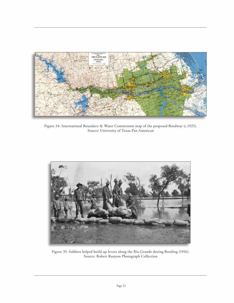
International Boundary & Water Commission map of the proposed floodway (c .1925) . Figure 34: Source: University of Texas-Pan American
Soldiers helped build up levees along the Rio Grande during flooding (1916) . Figure 35: Source: Robert Runyon Photograph Collection
Page 52

Route of the Southern Pacific railroad lines through the Valley . Figure 36: Source: Harding and Lee, Rails to the Rio
Page 53
Improvements in Transportation and Infrastructure
In 1921, the first hard surfaced roadway opened to connect the Valley with San Antonio, bringing life to truck farming in the area . San Antonio was quickly becoming the hub for agricultural products in Texas, whether it was the regional distribution of produce or the shipping of products out of state via railroads .
In 1924, the Missouri Pacific acquired the Gulf Coast Lines, allowing more direct access to mar-kets . Previously, freight cars would have to stop in transit and transfer their cars to other lines, as the Gulf Coast Lines had limited service . The Missouri Pacific, however, spanned the country allowing for shorter transit times for fragile produce . The new railway also added additional freight depots throughout the Valley so that “no farm in the irrigated portion of the Valley is farther than five miles from a loading station .”12 Additional improvements were made to the tracks and, for the first time, an adequate number of freight cars were provided to the Valley .13
12 . Watson, 59 .13 . Ibid .

Icing railroad cars in Harlingen (c .1930) . Figure 37: Source: Watson, Lower Rio Grande Valley and Its Builders
Page 54
During the 1920s, facilities for shipping vegetables improved considerably . Large packing sheds with improved railroad facilities vastly improved the shipping of vegetables . One of the most impor-tant developments was the refrigerator car provided by the American Refrigerator Transit Company, a subsidiary of the Missouri Pacific . These cars, combined with icing facilities, improved the ability to transport perishable vegetables over long distances . These refrigerated cars were given the right-of-way and treated like express shipments .14 By 1927, the Southern Pacific Railroad linked Brownsville to San Antonio, as well as Los Fresnos, Harlingen, McAllen, and Edinburg .15 The Southern Pacific Railway also provided facilities that encouraged further development of agriculture to the Valley; for the first time, there were an adequate number of freight cars for farmers . More importantly, efficient icing stations at freight depots could ice down 60 carloads of citrus and vegetables in a very short period of time .16
The icing of the cars required the development of a parallel industry during this period . In 1922, the Valley Electric & Ice Company began operations . This company rapidly acquired most of the ic-ing facilities in the Valley and was reorganized as the Central Power and Light Company in 1925 . By the end of the decade, it provided electricity, water and ice to more than 14,000 homes .17 The company introduced the most modern facilities for icing fruit and vegetables to the Valley . With the introduction of modern ice facilities, early winter vegetables could be shipped in refrigerated boxcars to sell at least two months earlier than crops from other areas of the country . Cabbage became an important export, bound for the East Coast where the vegetable was a popular mainstay among ethnic immigrants . Tomatoes, potatoes, and onions were also important exports .18
In 1926, the Rio Grande Valley Gas Company began securing the infrastructure to bring natu-ral gas to the Valley . Ready availability of natural gas would not only bring industrial development to the Valley, but would also provide an alternative fuel for many of the river pumping plants .19
14 . Ibid ., 147-149 .15 . Ibid ., 53 .16 . Ibid ., 55 . 17 . Ibid ., 161 .18 . Kearney and Knopp, 224 .19 . Ibid .

Shaved ice was blown over baskets of vegetables packed in railroad cars . Figure 38: Source: “The Texas Delta of an American Nile,” National Geographic Magazine, January, 1939
Assembly lines automated the icing of produce for shipping . Figure 39: Source: “The Texas Delta of an American Nile,” National Geographic Magazine, January, 1939
Page 55

An expansive citrus grove near Brownsville during the late 1920s . Figure 40: Source: Book of Texas, 1928
Page 56
The Development of the Citrus Industry
Numerous local sources cite the oldest known citrus trees as those on the Laguna Seca Ranch (also known as the Old Macedonia Vela Ranch), located 20 miles northwest of Edinburg . Planted in 1869 or 1870 from seeds brought by one of the Oblate Fathers, the orange trees were supposedly still living in 1931 .20 Individual citrus trees of some age are found throughout the Valley . B .C . Crafton may have planted the earliest grapefruit tree in the Lone Palm Grove near Mercedes about 1907 .21 R . Cummings planted an acre of Marsh seedless grapefruit trees near Donna around 1911, and Mrs . E .V . Flores owned a tangerine tree on the El Jardin De Flores Ranch at Oje de Agua that dated from the turn of the century .22
Charles Volz planted one of the first true orchards in the Valley south of Mission around 1907 . It took almost ten years before his efforts began to bear fruit . Densely planted on two acres were 189 orange trees, 12 grapefruit trees, 19 lemon trees, and 2 tangerine trees . He reportedly made $1,500 an acre once the trees matured, although his market was almost entirely local . But the high returns on his crops elicited a great deal of interest in citrus .23 In 1908, W .C . Griffing opened one of the first citrus tree nurseries near McAllen . Griffing was from Florida, where he owned the Griffing Brothers Nursery .24 Many of the earliest citrus trees available in the Valley were imported from Florida and California .
The commercial development of citrus blossomed in the Valley in the 1920s . The cultivation of citrus is profitable because so few areas of the United States provide the climatic requirements to grow the fruit . Only parts of Texas, California, Florida and Arizona are able to sustain the citrus industry, and during this period, there was a growing demand from consumers for citrus fruit . Developing a profitable citrus orchard required only a small portion of land, and while waiting for the trees to mature, farmers planted other crops, such as vegetables, between the lines of developing trees .
20 . Watson, 101 .21 . Ibid .22 . Ibid ., 101, 105 .23 . Ibid ., 105 .24 . Ibid ., 107 .

Fruit pickers filling field boxes headed for packing sheds . Figure 41: Source: Gerhardt and Tamez, Images of America: Weslaco, Texas
Page 57
John H . Shary became the leading developer of the citrus industry in the Rio Grande Valley . Arriving in 1914, he first developed a tract of land near Mission known as Sharyland . Subsequently, he acquired the Mission Canal Company, which he developed into the United Irrigation Company, one of the longest operating private irrigation companies in the Valley (1915-1952) . He developed a marketing scheme that allowed prospective buyers to merely invest in the land; his company supplied the trees from his nurseries, the irrigation water, the labor for cultivation and harvesting, the packing plant and facilities, and final marketing of the product .
Shary’s development model became popular with developers across the Valley who followed his lead and marketed the land and the citrus groves to Midwesterners as investment property rather than farm homesteads, as was done in the past . The purchaser bought the land, and the developer planted the citrus, maintained the groves, and harvested the fruit when the trees matured . The property owner simply sat back and watched the profits pour in . Then, when the owner was ready to retire, he could move to South Texas and live on his land . Developers often touted that the profits from a citrus grove could allow the owner to retire early, often within just a few years after his trees matured .25
The first citrus shipments out of the Valley occurred in the winter of 1921 .26 With the growing availability of nursery stock, more farmers invested in citrus . Between 1920 and 1921, 300,000 trees were planted, of which only 50,000 had actually been grown in the Valley . In 1924, 440,000 trees were planted; 340,000 of the trees were Valley-grown from nursery stock in the area .27 Some sources put the number as high as one and a half million orange and grapefruit trees planted by 1923 .28 By 1925, there were 2 million citrus trees planted in the Lower Rio Grande Valley .29 By 1930, according to the citrus census of the U .S . Department of Agriculture, there were 6,001,101 citrus trees planted, including 4,201,650 grapefruit and 1,440,122 orange trees .30
25 . Ibid ., 109 .26 . McNail, 4 .27 . Watson, 107 .28 . McNail, 5 .29 . Watson, 109 .30 . Ibid .

Specialized Figure 42: conveyers helped reduce damage to fragile citrus produce during packing .
Source: American Memories Collection, Library of Congress
Page 58
The grapefruit of the Valley was known as pomelo, but became popularly known as “grapefruit” because it grows in clusters on trees like grapes . The most common varieties grown were Duncan, Foster and Marsh, although many others were also cultivated .31 The Valley is well known for its pink-fleshed grapefruits . The varieties of oranges cultivated in the Valley include Navel, Parson Brown, Pineapple, Norris, Hamlin, Ramona, Lue Gim Gong, Valencia, Tangerine, Tangelo, and Mandarin .32 The Valley is most famous, however, for its “Ruby Red” grapefruit . This delicious citrus developed by accident from the pink-f leshed grapefruit, originally developed in Florida in the early 1910s . The Ruby Red was developed almost simultaneously by Dr . Webb and A .E . Henninger; each found a hybrid of the fruit growing in their orchards . The new hybrid had a distinctive red blush on the rind and tasted much sweeter than the blander Florida grapefruit .33
Because of its fragile nature, the handling of fruit from the grove to the market required special measures . As fruit bruises easily, care is essential in all steps to prevent damage to the product . Fruit pickers wore gloves to prevent bruising, and wagons or trucks had heavy-duty springs to prevent jostling . Packing houses used conveyor belts to minimize the amount of handling . As the fruit rolled along, it was graded and sized by dropping through openings of various diameters, called sizers, to padded bins below . Packers wrapped the fruit in paper within boxes to further protect the fragile product during shipping .34
As a result of the intricacies of moving fruit to its final destination, cooperatives and private packing plants emerged to deal with the operation . Local growers organized the Texas Citrus Fruit Growers Exchange, a co-operative run at cost to its members . It operated seven packing plants in Sharyland, Mercedes, Harlingen, La Feria, San Benito, Donna, and Edinburg . The Exchange was responsible for grading, packing, and shipping the fruit through its packing plants . The costs of materials, labor and overhead were deducted from the profits of the citrus, established by a fixed price set for the fruit at the beginning of the year . The exchange also sold the fruit at markets across the country, charging a fixed-sales commission of 20¢ a crate . Resulting profits, if any, were distributed among the members of the exchange .35 Thus, it became important that each exchange or selling agency was identified by its unique signage on the boxes and crates of all produce packed and shipped .
31 . Ibid ., 103 .32 . Ibid .33 . “Red Grapefruit Called Million Dollar Mistake,” in Lower Rio Grande Yearbook (1968), 31 .34 . Watson, 113 .35 . Ibid .

The Growers Exchange operations included Figure 43: shipping local produce, such as this railroad car of cabbage in Alamo .
Source: Russell Lee, 1939, Farm Service Administration, Library of Congress
Crate label for F .H . Vahlsing of Elsa, Figure 44: one of the Valley’s largest growers, packers and shippers .
Source: Knight & Associates
Page 59

The Donna Citrus Association packing shed was a typical operation for Figure 45: distribution of a variety of produce from the Rio Grande Valley in the 1920s.
Source: Gerhardt and Tamez, Images of America: Weslaco, Texas
Page 60
The Nation’s Truck Farm
The Rio Grande Valley became known as “The Nation’s Truck Farm,” with its growing season extending from early fall through the spring. Due to this long and bountiful growing season, Valley farmers were shipping vegetables to northern markets when fields in those outlets were still covered with snow.
Vegetable shipments increased substantially, from 343 railcars in 1920 to 3,891 cars in 1925, and 6,632 cars by 1928.36 With the Valley 700 miles closer to the Eastern markets than their California competitors, fruits and vegetables could be shipped by either rail or water. By the 1928-1929 season, 23,000 rail cars of vegetables were shipped out of the Valley.37 A variety of fancy vegetables became increasingly popular, including asparagus, celery, parsley, dandelions, escarole, broccoli, romaine, English peas, shallots, and eggplant.38
By the end of the decade, Valley farmers were increasingly diversifying, growing vegetables, citrus, cotton, and raising livestock. The 1929 cotton crop produced 100,000 bales of cotton valued at $11,000,000.39 Farmers were able to grow cotton on the same acreage after their vegetable crops were complete, significantly increasing the productivity of their farms. Throughout the 1920s, Hidalgo and Cameron counties ranked among some of the largest cotton producers in the State. Moreover, they produced some of the earliest cotton brought to market, thus resulting in the best possible prices. By 1929, the Valley had 103 cotton gins and 2 compresses (at Harlingen and Edinburg).40
36. McNail, 5.37. Watson, 147.38. Ibid.39. Ibid., 149.40. Ibid., 149, 151.

Page 61
Changes in Water Law and the Creation of New Irrigation Districts
Passage of a new law in 1925 allowed the establishment of water control and improvement districts that held broader powers than previously afforded the original districts. This act permit-ted the new districts to tax on an ad valorem or specific-benefit basis (or both), thus allowing the districts the operating capital they needed to both adequately maintain and improve their irrigation systems.41
A decision in Molt v. Boyd (1926) upheld the dual system of allowing both riparian water rights to coexist with State appropriation rights. With water rights secure, developers could continue to buy raw ranch land, form water control and improvement districts, develop irrigation systems through the sale of bonds, sell land to farmers, and continue to develop the Lower Rio Grande Valley.42 If land had no riparian water rights, a developer could obtain a permit from the Board of Water Engineers after submitting a certified filing from the county. The Board of Water Engineers did not have the power to deny a certified filing after the State Board of Water Engineers v. McKnight case in 1921. Since there was no notice required to other irrigators, over-appropriation of water went unchecked throughout the Valley.43
By the late 1920s, a number of new irrigation districts were formed, primarily as the result of private developers seeking funding for their enterprises. Over 300,000 acres were included in these new districts, with 129,000 acres in Willacy County alone. The majority of these new irrigation districts were in Cameron County, primarily along the Gulf Coast. Hidalgo County added only two new districts, Hidalgo County Water Improvement District No. 6 and Hidalgo County Water Control and Improvement District No. 6. Because they were developer driven, these new irriga-tion districts were much smaller in acreage and most had typically been dry-farmed for many years. Cameron County Water Improvement Districts No. 8, 10, 11, 12, 14, 15 and 16 were formed at this time and took the name of their respective subdivision developments, such as Engelman Gardens and Adams Gardens. By 1929, there were 28 irrigation districts in the Valley, including 14 in Cameron County, 12 in Hidalgo County, one in Willacy County, and one in Starr County.
The initial development of the Valley reached its peak in 1928 and 1929. Farmers used only 20% of the flow of the Rio Grande for irrigation at this time, with the remainder being released into the Gulf of Mexico; Mexico used very little of the water for irrigation purposes. Still, water shortages existed during periods of drought when the river flow was below normal.44
41. Stubbs, 16.42. Ibid., 13-14.43. Ibid., 16.44. Robertson, 1937.

New districts increased agricultural development in the Valley . Figure 46: Source: Gerhardt and Lincoln, Images of America: Donna, Texas
Aerial view of Hidalgo County WCID No . 5 at Progreso (established in 1925) . Figure 47: Source: National Geographic, January, 1939
Page 62

Early tourist facilities for visitors to the Texas Gulf Coast (c .1930) . Figure 48: Source: Watson, Lower Rio Grande Valley and Its Builders
Shopping across the border in the Mexican Figure 49: mercados (c .1920). Source: Robert Runyon Photograph Collection
Page 63
The culture of the Rio Grande Valley appealed to tourists as well as to farmers, land developers and entrepreneurs . With a year-round tourist season, only the lack of infrastructure such as lodging and recreational facilities prevented it from becoming a true destination point . In 1927, millions of dollars were invested in new hotel structures across the Valley . Golf courses sprang up and the numer-ous resacas and natural lakes, as well as proximity to the coast, made the area a “sportsman’s paradise .” The colorful border towns of Mexico and their bustling mercados for shopping offered yet another destination point for visitors . As a result, tourism enjoyed an enormous upswing and continued to boom, until the onslaught of the Depression brought it to a quick close .45
45 . Watson, 143, 151, 155 .

Year Number of Acres under Cultivation Diversion in Acre Feet from River
Page 64
1922 216,000 574,300
1923 237,000 611,700
1924 268,000 696,900
1925 298,000 799,200
1926 327,000 513,490
1927 343,000 860,400
1928 354,000 791,400
1929 370,000 764,700
1930 388,000 500,000
1931 335,000 484,750
1932 353,000 607,300
1933 323,000 516,310
1934 294,000 582,400
1935 327,000 549,700
1936 358,000 566,300
1937 321,000 653,300
1938 338,000 710,000 1939
1939 425,000 887,200
1940 504,910 914,600
1941 457,379472,500 Drought
1942 489,325 1,051,000
1943 543,119 1,025,400
Water Use for Cultivated Acres Lower Rio Grande Valley ~ 1922-1963

Year Number of Acres under Cultivation Diversion in Acre Feet from River
Page 65
1944 525,520957,500 Drought
1945 544,415 1,130,700
1946 600,735 1,114,400
1947 558,234 1,148,200
1948 588,720 1,043,600
1949 613,621 1,223,600
1950 602,380 1,489,800
1951 615,665 1,059,600
1952 506,684752,400 Drought
1953 466,891719,880 Drought
1954 648,6411,454,000
Opening, Falcon Dam
1955 671,768 1,581,400
1956 657,034 989,100
1957 760,900 732,200
1958 771,046 857,500
1959 773,014 1,069,800
1960 775,790 1,074,000
1961 775,284 1,071,800
1962 783,757 1,127,455
1963 780,693 879,054
Water use, contd.

Page 66
impaCt of tHE dEprEssion on tHE lowEr rio GrandE VallEy
The 1929 stock market crash and the resulting Depression became a death knell for the remaining privately owned irrigation companies . Land prices crashed in the Valley in 1929 and irrigated acreage declined; a recovery would take years . In 1929, a total of 371,000 acres were under irrigation; by 1930, irrigated acreage declined to 329,550 . The following year, the total steeply dropped to only 257,800 acres .1 Throughout the 1930s, the total of irrigated acreage in the Lower Rio Grande Valley fluctuated, reflecting the rocky economic period of the times . Even the well-financed American Rio Grande Land & Irrigation Company sold out to the farmers in 1930, becoming Hidalgo and Cameron Counties Water Control & Improvement District No . 9 .
Perhaps hardest hit by the Depression was Willacy County Water Control & Improvement District No . 1 (later reorganized as the Delta Lake Irrigation District) . Initially established in 1929, it boasted that it would become the largest irrigation project in the world, containing more than 129,500 acres within its boundaries .2 Initiated by W .A . Harding and George Lochrie on the Mestenas Tract, initial construction was delayed by an organized protest from all of the other districts who feared that the new system would appropriate too much water . This proposed $7,500,000 irrigation system would have featured the most modern construction methods of the time, including all concrete-lined canals and concrete underground pipelines . Pumping from the Rio Grande some 30 miles away, the water would be conveyed to a massive reservoir in northern Hidalgo County for storage before being distributed through the conveyance system . After redesigning the system to satisfy the demands of the other districts and cutting back the irrigated acreage to 75,000 acres, the Willacy County project encountered further setbacks with the crash of the bond market . Only $1 million in bonds could be sold by the turn of the decade and, much to the relief of the other districts, the project was delayed for years .3
By 1931, almost half a million acres were under irrigation in the Valley, with additional projects planned that would encompass another 600,000 acres . Not all the irrigated land was under cultivation . Sixteen irrigation systems supplied water to farmers, two of which were privately owned . The Mercedes-Rio Grande Land & Irrigation Company, successor to the American-Rio Grande Land & Irrigation Company, operated the largest pumping plant along the river, with two pumps capable of pumping 250,000 gallons of water per minute . The privately operated irrigation system contained 89,000 acres, with over 63,000 acres under cultivation .4
The bond indebtedness of the 1920s, which originally allowed for the formation of the irrigation districts, became an enormous burden on Valley farmers during the Depression . But it was not only the irrigation districts’ taxes that hurt them; an individual farmer also paid taxes to the county, the school district, the drainage district, and in some cases, to a road district . While tax remissions paid for the bonds issued in the 1920s funded the construction of the floodway, they did not pay for the interest on the flood control bonds . Additional county taxes were raised to pay for that expense, as well as to fund the main-tenance of the levees, which cost $75,000 to $100,000 annually . This pyramiding of tax and debt loads on small farmers eventually caused many of them to lose their land, as their payments on taxes alone became impossible .
1 . Hughes and Motheral, 29 .2 . Watson, 63 .3 . “Irrigation Was Started in Big Way in Willacy .”4 . Watson, 63 .
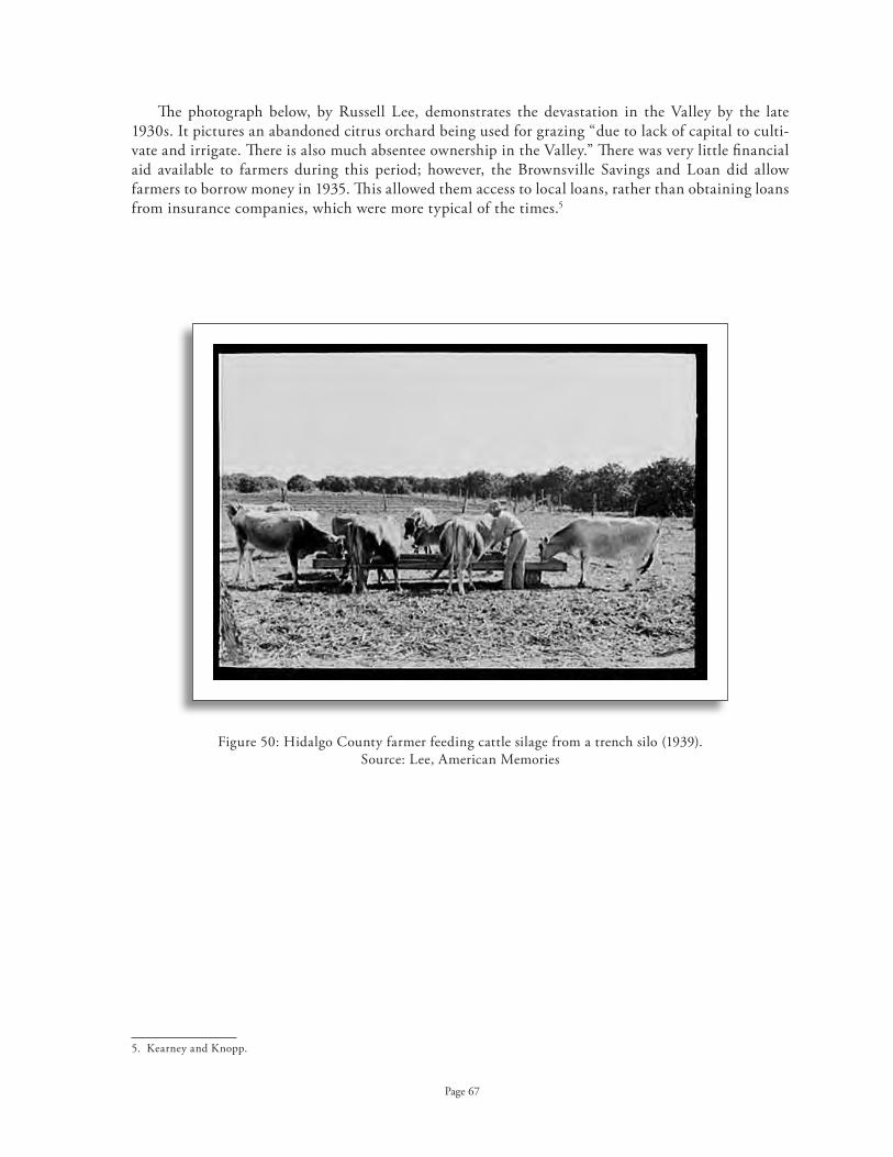
Hidalgo County farmer feeding cattle silage from a trench silo (1939) . Figure 50: Source: Lee, American Memories
Page 67
The photograph below, by Russell Lee, demonstrates the devastation in the Valley by the late 1930s . It pictures an abandoned citrus orchard being used for grazing “due to lack of capital to culti-vate and irrigate . There is also much absentee ownership in the Valley .” There was very little financial aid available to farmers during this period; however, the Brownsville Savings and Loan did allow farmers to borrow money in 1935 . This allowed them access to local loans, rather than obtaining loans from insurance companies, which were more typical of the times .5
5 . Kearney and Knopp .

Page 68
On September 5, 1933, a hurricane hit the Valley, dealing the entire area another serious blow . The resulting flooding and high winds were a catastrophic loss of orchards and crops .6 As a result, the Public Works Administration (PWA) funded $2 million to the International Boundary & Water Commission for rebuilding and strengthening the floodway .7 A later bill allowed for the federal government to take over the flood control project, including all future construction and ongoing maintenance . In 1936, Congress appropriated $1 .6 million for construction, but the counties were responsible for obtaining all right-of-way costs for the acquisition of property within the floodway .8
During 1930-1931, the number of rail cars shipping vegetables from the Valley totaled 21,295 . By 1931-1932, that number had declined to only 15,228 . Following the devastation of the 1933 hurri-cane, the number of cars shipping produce plummeted to only 7,313 . By 1936-1937, the numbers began to rebound, with a total shipment of 22,070 rail cars of vegetables and produce .
A number of New Deal programs provided aid to the people of the Rio Grande Valley during the Depression . The PWA provided funds to assist irrigation districts in lining miles of canals with concrete, providing labor-intensive work for many people . The availability of federal funds contributed to the growing popularity of concrete-lined canals . These canals helped meet the need to conserve energy costs at the districts’ pumping plants; the loss of water through seepage from earthen canals required additional pumping to deliver the same amount of water to farmers . Concrete-lined canals significantly cut seepage losses, allowing the districts to save considerably on their energy costs at the pumping plants .
Willacy County Water Control & Improvement District No . 1 finally acquired PWA funds for the construction of their $7 .5 million dollar irrigation system that had been stalled for years . However, the district engineer and several board members were indicted for taking bribes from a California contractor . Construction on the system finally began again in 1937 .9
In order to lessen the impact on out-of-work Americans, Congress passed immigration reform laws during the Depression that greatly impacted the Valley . The resulting deportation of Hispanics and their American-born children caused a crisis in the available labor pool in the region . Between 1928 and 1931, almost half a million Hispanics were deported from the United States .10 Outraged supporters from the Lower Rio Grande Valley lobbied Washington, as the lack of cheap labor only further exasperated economic conditions in the area . In 1933, President Roosevelt enacted the Good Neighbor Policy that once again allowed for cheap Hispanic labor in the Valley .
6 . McNail, 3 .7 . Robertson, 1937 .8 . Ibid .9 . “Irrigation Was Started in Big Way in Willacy,” (Brownsville Herald, Dec . 6, 1942) .10 . Kearney and Knopp .

Lining canals in Hidalgo County Water Improvement District No . 2 . Figure 51: Source: Brochu, Getting Up Steam
Concrete lining of an unidentified main canal (c .1930) . Figure 52: Source: Watson, Lower Rio Grande Valley and Its Builders
Page 69
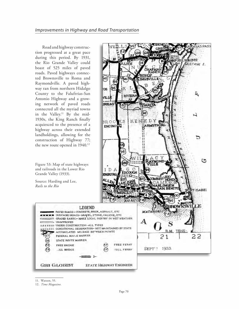
Map of state highways Figure 53: and railroads in the Lower Rio Grande Valley (1933) .
Source: Harding and Lee, Rails to the Rio
Page 70
Improvements in Highway and Road Transportation
Road and highway construc-tion progressed at a great pace during this period . By 1931, the Rio Grande Valley could boast of 525 miles of paved roads . Paved highways connec-ted Brownsville to Roma and Raymondville . A paved high-way ran from northern Hidalgo County to the Falufrrias-San Antonio Highway and a grow-ing network of paved roads connected all the myriad towns in the Valley .11 By the mid-1930s, the King Ranch finally acquiesced to the presence of a highway across their extended landholdings, allowing for the construction of Highway 77; the new route opened in 1940 .12
11 . Watson, 55 .12 . Time Magazine.

By the late 1930s, cotton was commonly shipped to market via the Port of Brownsville . Figure 54: Source: Robert Runyon Photograph Collection
Page 71
The Port of Brownsville opened in 1936 and would become the principal cotton port on the Gulf of Mexico . This provided area cotton growers with their most economical transportation to world markets . The Brownsville Navigation District, formed in 1928, worked for years to construct a canal from the Gulf to Brownsville . Bonds for the construction were passed in 1929 . Additional funding from the PWA in 1933 was critical in the final construction of the monumental canal at a cost more than $6 million .13 The channel, 17 miles long and 100 feet wide, was dredged between Brazos Santiago Pass and Brownsville and included a turning basin measuring 1,000 feet by 1,000 feet .14
13 . Kearney and Knopp .14 . Watson, 57 .

Page 72
world war ii and tHE VallEy
The post-World War II period brought an increased industrialization and modernization of the Lower Rio Grande Valley . The number of irrigated acreage declined during in 1941 and 1942, but the decline was due to heavy precipitation for those years, not the advent of the War .1 In 1940, Willacy County Water Control & Improvement District No . 1 finally completed the construction of their irrigation system, opening Willacy County to irrigation for the first time .2
Developer initiated irrigation districts had continued to thrive . The beginning of World War II tem-porarily interrupted the development process, as a shortage of materials made it impossible to construct new irrigation systems . Hidalgo County Water Control & Improvement District No . 15 (Santa Cruz) was the last to organize, in 1941, before the outbreak of war . The first phase of the irrigation system, however, was not completed until 1947 . The district encompassed the Santa Cruz Gardens development, which focused on citrus groves . This would be the last such irrigation development entirely situated within the third and fourth bench lands . In addition to a shortage of materials, the War caused severe labor shortages in most industries . The labor shortage was addressed by introduction of the Bracero Program in 1942, which allowed farm owners to contract with Mexican workers .
The further expansion of irrigated acreage in the Lower Rio Grande Valley depended heavily upon the passage of a treaty with Mexico that would enable the United States to construct storage dams in the Rio Grande River . Most of the water in the river simply passed by the irrigation districts’ pumping facilities and emptied into the Gulf of Mexico . During periods of drought, the river slowed to a trickle and the irrigation districts downstream, especially in Cameron County, could not even pump from the river . A storage dam would allow for a regulated flow of the river and allow for much needed conservation of the Valley’s most important natural resource .
An International Water Treaty with Mexico was finally signed in 1944, requiring only Senate ratifi-cation . But Mexico negotiated a certain a percentage of water from the Colorado River watershed within the terms of the treaty, leading California and other Western states to protest the final ratification . Since California constituted the biggest competitor with both the Valley and Mexico in the production of citrus and vegetables, it could damage both of its biggest rivals if it could stop the ratification of the treaty . Water districts and large commercial farmers in Southern California spent huge sums of money in a propaganda campaign to defeat the treaty . Their efforts ultimately failed and the final ratification of the treaty on November 8, 1945, opened the way for the construction of dams in the lower Rio Grande for the conservation and storage of water .3
1 . Hughes and Motheral, 29 .2 . “Irrigation Was Started in Big Way in Willacy .”3 . John O’ Grady, “Test of a Good Neighbor,” Commonwealth (Feb . 16, 1945), 438 and McNail, 30 .

Following World War II, the number of irrigated acres in the Figure 55: Valley flourished, as seen in this aerial photograph of citrus groves near McCook .
Source: Lower Rio Grande Yearbook, 1950
Page 73
Although plans for a storage dam began immediately, it would be another decade before the first such dam at Falcon became a reality . Yet the optimism for a future plentiful water source, coupled with high wartime prices for agricultural produce, stimulated production in the Valley . At the time of the signing of the 1944 International Treaty with Mexico, 550,000 acres were under irrigation in the Lower Rio Grande Valley .4 Between 1942 and 1949, irrigated acreage increased at an average rate of 37,000 acres per year .5 Vegetable shipments increased from 24,046 rail cars in 1942 to 36,512 rail cars in 1946 .6 Citrus production of 24,358 rail cars in 1942 expanded to 34,757 rail cars by 1946 .7
4 . Tate Dalrymple, The Water Situation in the Lower Rio Grande Valley, 3 .5 . Hughes and Motheral, 29 .6 . McNail, 5-6 .7 . Ibid .

Grapefruit from Alamo stacked to look like a fireplace at an agricultural fair in the Valley . Figure 56: Source: Robert Runyon Photograph Collection
Page 74
In 1948, there were 28 active irrigation districts in the Valley, encompassing 556,609 acres and 3,277 miles of both main canals and laterals . In addition, there were 124 independent irrigation projects covering 26,391 acres; only 1,448 miles of drainage ditches had been constructed by this time .8 The counties of Cameron, Hidalgo, Willacy and Starr held a combined total of 460,000 acres under irrigation .9
F .H . Vahlsing Inc ., one of the country’s largest vegetable marketing distributors, owned 25,000 acres in the vicinity of Elsa . Managed by Melvin Giese, who also served as the Mayor of Elsa, the company introduced the use of snow icing to the Valley . This technique completely covered the produce contained within a railroad car with finely shaved ice and protected it, eliminating the need for re-icings during transit .10
The Rio Grande Citrus Exchange introduced another innovative technology in the 1940s with the construction of dehydrating plants at Weslaco . These plants converted grapefruit peel into feed for livestock, recycling a by-product that had been dumped as waste and producing a supplement feed used by both ranchers and farmers .11
8 . Ibid ., 31 .9 . Ibid ., 2 .10 . Hidalgo County Centennial, 1852-1952, 31 .11 . McNail, 5 .

Palm trees often lined concrete highways throughout South Texas . Figure 57: Source: Watson, Lower Rio Grande Valley and Its Builders
Page 75
By 1946, Highway 83 (originally constructed of concrete) became known as the “Main Street of the Valley;” the route linked 42 suburban towns between Brownsville and Starr County with a popu-lation of 185,400 .12 During this same time, Mexico began exploiting the Rio Grande for irrigation projects on a vast scale . Below Elephant Butte Dam, 174,133 acres were under irrigation in 1948, and by 1949, 89,278 acres were under irrigation at Azucar near Rio San Juan . The Retamal Intake Canal near Hidalgo placed 113,668 acres under irrigation by 1950 and the Anzalduas intake canal was under construction by the early 1950s . This expansion of irrigation on the south side of the Rio Grande caused great concern among the irrigation districts, particularly during periods of drought .13
One of the last towns to develop in the Valley was the “Baby City” of Linn, sited at the intersec-tion of Highways 281 and 186, north of Edinburg . The former town of Linn was actually moved from its 1926 site by the Guerra Brothers to the new townsite laid out by C .R . Parliman, an industrial engineer . Parliman’s firm, Parliman Technical Care, developed the Fresh Water Farms develop-ment in 72,000 acres surrounding the site . Water was supplied from shallow wells in the area, one of the earliest uses of groundwater . Parliman laid out the town with roads 60 feet wide, designing the roadways to be lined with palms . Little of the newly designed town, however, came to fruition . The Guerra Brothers constructed a gas station and a general store in matching Austin stone, but their plans for an exclusive residential area, Linn Estates, never materialized .14
12 . Ibid ., 7 and “The Strangest Street,” The American City (Nov . 1946), 7 .13 . Testimony before State Legislative Sub-Committee, box 2, folder .0766 Cramer Collection,
Museum of South Texas History Archives .14 . Yearbook of the Lower Rio Grande Valley and Northern Mexico (1950), 105-106 .

Page 76
The end of An erA: The TrAnsformATion of The AgriculTurAl economy of The lower rio grAnd VAlley
The death of John Shary in 1945 marked the end of an era in the Lower Rio Grande Valley. The dissolution of his United Irrigation Company in the years following his death scattered the final remnants of his private companies responsible for the Valley’s early development. The last vestiges of the United Irrigation Company’s irrigation system were sold off to the area farmers in the irrigation districts of Hidalgo County WCID No. 7 and No. 14 in 1952. Hidalgo County Water Control & Irrigation District No. 19 (Sharyland) was established in 1952, the last irrigation district to be initi-ated in the Lower Rio Grande Valley.
The Valley experienced a series of natural events from the late 1940s throughout the 1950s that devastated agricultural production. A severe drought, compounded by a series of freezes and hurricanes, destroyed the millions of the citrus trees planted in the late 1920s and 1930s. The agricultural economy of the Valley would not recover entirely until the early 1970s. But perhaps more importantly, the construction of Falcon Dam (1950-1953) and the subsequent regulation of water of the Rio Grande River by federal and state agencies represented a dramatic turning point in the agricultural development in the Valley. The unlimited development of the Valley experienced in earlier decades would henceforth be restrained by the availability of water and regulation by the State of Texas. Water conservation would become a way of life for the Valley.
After this devastating series of natural disasters of drought and freezes, many of the smaller farms became unprofitable. Only the larger growers were able to survive the decades-long battle with drought, freezes and hurricanes, and not without enormous struggles. As a result, the post-World War II period brought an increased modernization and industrialization of the Lower Rio Grande Valley.
Catastrophe strikes the MagiC Valley
Throughout the late 1940s and 1950s, a series of catastrophic natural events devastated the farms of the Valley. The citrus groves in the Valley supplied 40% of the country’s grapefruit, but a series of deadly freezes and drought crippled the industry.
1
A freeze hit the area in January of 1949 followed by a drought in the late spring. While the freeze of 1949 caused severe damage to the citrus crops, the 1951 freeze two years later killed millions of trees. Approximately 20,000 citrus farmers lost 11 mil-lion trees valued at $200 million.2 Whereas the Valley shipped 36,545 railroad cars of citrus before the 1949 freeze, the area shipped only 5,436 railroad cars the following season. Following the 1951 freeze, this number dropped to its lowest point ever at only 244 railroad cars for 1952. This series of freezes was followed by the most tenacious drought ever recorded in Texas, between 1951 and 1956. Beginning in the Valley in the late spring of 1949, the drought had spread throughout the entire state by 1951. Between 1954 and 1956 conditions only worsened. Some relief came to the Valley in 1954 with rainfall, but Hurricane Alice also struck in June of that year, causing flooding and damaging to crops. The drought, freezes, hurricanes, and low prices also impacted vegetable farming. Whereas the Valley boasted 35 vegetable canners in 1947, by 1957 only 12 such canning operations survived.3
1. McNail, 7.2. Dick Heller, “History of Mission,” 84.3. Ibid., 157.

YearCitrus
Total Railroad CarlotsVegetables
Total Railroad Carlots
Page 77
1916Freeze
0 1,998
1917Freeze
NA NA
1918 NA NA
1919Flood
NA NA
1920 0 NA
1921 1 NA
1922Flood
26 NA
1923 64 NA
1924 186 11,286
1925 659 10,515
1926 523 12,975
1927 1,066 13,423
1928 1,154 17,704
1929 1,835 20,737
1930 4,135 20,281
1931 2,654 23,316
1932 5,767 14,461
1933Hurricane
2,066 13,872
1934 2,543 14,376
1935 5,547 7,877
Lower Rio Grande Valley Produce Totals1916 – 1968

YearCitrus
Total Railroad CarlotsVegetables
Total Railroad Carlots
Page 78
1936 7,039 19,302
1937 22,775 NA
1938 NA NA
1939 27,760 14,732
1940 11,724 14,713
1941 24,000 NA
1942 24,358 NA
1943 25,841 NA
1944 27,812 NA
1945 33,610 NA
1946 34,757 NA
1947 36,176 NA
1948Drought
36,545 NA
1949Freeze and drought
5,436 23,737
1950 3,680 24,652
1951Freeze and drought
1,372 9,737
1952Drought
244 17,777
1953Hurricane and drought
345 21,216
1954Drought
1,793 22,287
Produce totals, contd.

Source of information for citrus and vegetables: United States Department of Agriculture (1916-1968)
The 1917-1923 annual marketing figures are for fruit only as vegetables are not yet included . From 1917-1923, 1937-1938, and 1941-1948, statistics are available on a statewide basis only . As the Lower Rio Grande Valley was the only source of citrus, these figures were taken from the statewide production numbers for these years . The 1938 bulletin was not available .
Carlot statistics include only information for the following fruits and vegetables: grapefruit, oranges and tan-gerines, mixed citrus, broccoli, cabbage, cantaloupes, carrots, cauliflower, celery, green corn, cucumbers, en-dive, greens, honeydews, lettuce, onion, peppers, potatoes, spinach, tomatoes, turnips, watermelons, and mixed vegetables .
YearCitrus
Total Railroad CarlotsVegetables
Total Railroad Carlots
Page 79
1955Drought
1,992 20,996
1956Hurricane and drought
2,874 22,359
1957Drought
4,692 13,140
1958 1,164 17,151
1959 7,198 13,487
1960 9,517 18,125
1961 14,616 14,177
1962Freeze
1,189 10,661
1963Freeze
878 14,220
1964 2,184 14,131
1965 3,733 13,504
1966 7,004 8,142
1967Hurricane
9,191 9,676
1968 6,463 7,030
Produce totals, contd.

View of an orchard after the freeze of 1951 . Figure 58: Source: Ken Anderson
Page 80
The increase in the number of acres irrigated in the Valley during the 1950s, compounded by the severe drought in 1941, 1944, and 1948-1957, resulted in a historic decline in the flow of the Rio Grande River by 1956 . With the devastation of the citrus industry and the lack of adequate supplies of irrigation water, area farmers turned once again to growing cotton, which required far less water . Cotton production reached a new peak in the Valley during the mid-1950s due to high prices on the world market, especially in England, Canada, Belgium, Italy, India, and Japan .
4
In 1949, 200,000 bales of cotton were ginned in Hidalgo County .
5
In 1959, 470,00 bales were ginned, yielding $90 million in income, the third largest cotton harvest in the Valley’s history after 1949 and 1951 . Moreover, cheap labor was still available to growers in the Valley, as the Migrant Labor Agreement of 1951 allowed Mexican workers to stay in the United States for up to 18 months as long as they did not displace any American workers . The Bracero program continued in operation until 1964 . Increasingly, however, farm workers were being displaced by farm machinery in the 1950s .
6
Mechanical pickers were utilized to harvest an estimated 30 to 40% of the cotton crop by 1959 .
7
By the late 1950s, however, cotton prices began to fall and totally collapsed in 1962 .
8
4 . Kearney and Knopp .5 . Yearbook of the Lower Rio Grande Valley and Northern Mexico (1950), 53 .6 . Ibid .7 . Ibid ., 15 . 8 . Kearney and Knopp .

Page 81
Falcon ReseRvoiR and the WateR cRisis oF the 1950s
During the drought that began in the summer of 1948, the irrigation districts operated on voluntary rationing. This agreement broke down in January of 1952, leading Cameron County WCID No. 5 to file a restraining order against the users of the Rio Grande River with operations located upstream. The judge granted the restraining order and also ordered a survey of all the users and their minimum requirements.
9
Constructed for the purposes of water conservation, irrigation, power, flood-control and recre-ation, Falcon Dam was begun in 1950 and became operational in August of 1953; it was completed in April of 1954 with the installation of power equipment and the spillway control gates. The dam is almost five miles long and rises 150 feet above the bed of the river. In a historic ceremony, Mexican President Adolfo Ruiz Corines and President Dwight D. Eisenhower participated in the dedication ceremony of Falcon, the first in a series of dams made possible under the 1944 International Water Treaty. The dam holds a storage capacity of 4,085,000 acre-feet, of which 2,100,000 were designated for irrigation and power on the American side. Falcon Reservoir represented the finalization of years of struggle to obtain control over the waters of the Rio Grande, both for the economic benefits of ir-rigation and the control of its devastating floodwaters.
10
Fortuitously, heavy rains in late August and September of 1953 entirely filled the reservoir to capacity.
The opening of Falcon Dam, coupled with the intense drought of the 1950s, instigated a war over water in the Lower Rio Grande Valley. The International Water Treaty of 1944 established an annual share of water from the proposed reservoir to be jointly administered and distributed to Mexico and the United States. The natural flow of the river would be replaced with a regulated flow through the dam, with the level of the river determined by the amount of water requested by users downstream. The American share of 1,234,000 acre-feet per year would now be closely monitored and distributed among the irrigation districts. The treaty did not give the federal government the authority to control the distribution of water within the United States, thus requiring a plan between the State of Texas and the International Boundary and Water Commission to regulate the release of water from the dam.
In order to efficiently and fairly distribute the waters at Falcon, it would be necessary for each water user to have a set allotment. Yet, the existing water laws of Texas, that recognized both riparian and appropriation water rights, allowed water users to continue to divert water as they saw fit. As a result, it became necessary to continue to release additional water to ensure that the irrigation districts downstream actually received the water they requested; otherwise someone between their pumping plant and the dam would capture the water first. The drought and the expansion of irrigated lands in the Valley led to concerns of insufficient amounts of water at Falcon Reservoir. At the time of the signing of the treaty in 1944, there were approximately 475,000 acres under irrigation. By 1953, when Falcon Dam became operational, there were over 650,000 acres under irrigation in Hidalgo, Cameron, Willacy and Starr Counties. An attempt to pass a state law to control the waters of the Rio Grande failed. Ultimately, only the adjudication of the water rights of the Lower Rio Grande Valley would solve the complicated issue of centuries of water rights.
11
9. 21st Annual Report of the Board of Water Engineers (1952-1954), 27.10. Ibid.11. Testimony before State Legislative Sub-Committee, box 2, folder .0766 Cramer Collection, Museum of South Texas History
Archives.

The construction of Falcon dam Figure 59: in the early 1950s addressed both irriga-tion and water conservation needs in the Lower Rio Grande Valley .
Source: International Boundary and Water Commission
International Boundary and Water Commission map of Falcon Dam and Reservoir (1990) . Figure 60: Source: International Boundary and Water Commission
Page 82

Page 83
Water users below the dam attempted to organize, utilizing an agreement known as the Falcon Water Compact . In the spring of 1953, a “Trial Compact” was drafted for the distribution of the waters of the Rio Grande below Falcon Dam with a stated purpose of “providing for fair and equi-table distribution of all available waters of the Rio Grande during the present shortage and pending completion of the Falcon International Dam and the storage of water therein; and also to provide factual basis for a permanent agreement with respect to the conservation, storage and distribution of water .” The trial compact would extend to September 1, 1955, or one year after the Dam reached 2,100,000 acre-feet . The Compact appointed a Board of Water Trustees and a Water Master to over see the distribution of the waters . Distribution of water was based on a pro rata per acre basis, based on the acreage under actual cultivation . The districts to be included were listed by the land grants they occupied with the exception of Hidalgo County WCID No . 1, Cameron County WCID No . 1 and Cameron County WCID No . 3 .
12
The Compact, however, would exclude some of the older districts, while allowing new and ex-panded developments to continue to utilize the river’s water . Off-river districts, or those districts that received their water through the pumping plants of other districts, would potentially have no rights to water under the Trial Compact .
13
Three irrigation districts, Hidalgo County WID No . 6 (Engelman Gardens), Hidalgo County WCID No . 7, and Willacy County WCID No . 1 refused to sign the Compact, as they believed such an agreement would forfeit their rights to invoke the Treaty to restrain anyone who was diverting water unlawfully . They maintained that “lands introduced to irrigation af-ter the United States-Mexico treaty of 1945 have no right to water in the Falcon Reservoir .” Since the Compact agreed to divide the waters of the Rio Grande with post-1945 irrigators, the three districts could be relinquishing their rights under the Treaty .
14
Governor Shivers held several meetings during the spring of 1953 to try and resolve the issues between the irrigation districts, as well as individual users . It quickly became apparent that the water users of the Lower Rio Grande Valley would be unable to reach an agreement and form an organization that would represent all concerned . On August 31, 1953, Governor Shivers, at the request of Secretary of State Dulles, designated the Board of Water Engineers at the state agency from which the irrigation districts would request future releases from Falcon Dam, thus preventing Federal control of the distribution of State waters .
15
Kenneth Smith was employed as the water master of the Falcon Water Compact in January of 1954 . At that time, 24 water districts and 44 independent irrigators had signed the Compact .
16
The water master of this organization relayed their requests for water to the Board of Water engineers . The remaining irrigation districts and individual irrigators had a single representative, A .L . Cramer, who represented their requests . Upon receiving the requests, the Board of Water Engineers informed the International Boundary and Water Commission of how much water should be released . A third group of water users, however, continued to pump whenever they so desired without formally requesting re-leases from Falcon Reservoir . Although these were generally small farmers with no more than 200 to 1200 acre tracts, they accounted for more than 65,000 acres between Roma and Brownsville . During peak irrigation periods, their unregulated pumping from the river wreaked havoc with the system .
17
12 . Draft of Trial Compact, box 2, Cramer Collection, Museum of South Texas History Archives .13 . Attorney Sawnie Smith to Hidalgo County WID No . 6, box 2, folder .076 Cramer Collection, Museum of South Texas History
Archives .14 . Undated newspaper clipping, “Three Districts in Firm Stand on Falcon Water,” Irrigation Scrapbook,Museum of South Texas His-
tory Archives .15 . Twenty First Annual Report of the Board of Water Engineers, 1952-1954, 6, 28 .16 . Testimony before State Legislative Sub-Committee (box 2, folder .0766) Cramer Collection,
Museum of South Texas History Archives17 . Twenty First Annual Report of the Board of Water Engineers (1952-1954), 28 .

Falcon Dam and Reservoir as it appears today . Figure 61: Source: Texas Department of Transportation
Aerial view of Falcon Dam . Figure 62: Source: Google Earth
Page 84

Page 85
The Board of Water Engineers reported that the lack of a comprehensive state law for the adjudi-cation of water rights resulted in a “water rights dilemma;”
18
claimed water rights in the Valley far ex-ceeded the actual water supply of the Rio Grande River . In 1953, the Board of Water Engineers issued a resolution that they would no longer approve plans for the formation of any new irrigation districts in the Lower Rio Grande Valley . They also issued a similar resolution that plans for the expansion of existing districts would not be approved, but politics would play a role in the continuing expansion of several recently formed districts .
In order to administer the releases from Falcon Dam efficiently and fairly, the State had to de-termine a basis for establishing water rights . As a result, the State of Texas filed suit in 1956 against the water districts and other water users in the landmark case, State of Texas v. Hidalgo County Water Control and Improvement District No. 18 et. al. (1969), that ultimately led to the adjudication of wa-ter rights throughout the Lower Rio Grande Valley . Commonly called the Lower Rio Grande Valley Water Suit, the litigants included: 42 water districts; 2,500 individuals; cities and water companies; and more than 90 attorneys . The trial finally took place in the 93rd District Court between 1964 and 1966, with a final judgement filed in appellate court in 1969 . As a result, the suit established priority categories of water rights with domestic, municipal and industrial (DMI) rights holding the high-est priority . Irrigation rights, designated as Class A and Class B, held residual claim on the waters of the Falcon Reservoir . Class A water rights (641,221 acres) included those litigants who could prove riparian, prior appropriation, or Spanish/Mexican land grants . Class B water rights (101,588 acres) were assigned to those who merely had a history of diversion of water . Class A irrigators accrue water in storage at a rate 1 .7 times that of Class B irrigators, and thus are allowed more water during lean years .
19
As the case did not resolve the problem of over-appropriation of water, irrigation rights may be purchased and converted to other types of rights (such as municipal) only at a two-to-one conver-sion . Eventually, this may correct the historic over-appropriation of water in the Lower Rio Grande Valley .
20
During the course of the lawsuit, the dual system of riparian and appropriation water rights ended with the resolution of the State v. Valmont Plantations (1961) . In this case, the court overturned Molt v. Boyd and held that all Spanish and Mexican grants resulted from transferring public property to private ownership that had ultimately emanated from the Crown and were not riparian in nature un-til the introduction of Common Law under the Texas Republic . Since riparian law was subsequently repealed, this applied to Spanish and Mexican grants as well .
21
The Water Rights Adjudication Act, passed in 1967, created an administrative and judicial system for resolving water rights in Texas to forestall any other lengthy lawsuits such as the State v. Hidalgo County Water Control and Improvement District No. 18 .
2 2
Today, any appropriation from a Texas stream must be made by application to the Texas Commission on Environmental Quality .
Water shortages continued to plague the Valley during the drought of the 1950s . The available American share of Falcon Reservoir decreased in five months from 1,005,100 acre-feet on October 31, 1953 to only 40,000 acre-feet on April 7, 1954 . Heavy rains brought the amount back up to 205,000 acre-feet by May 1, 1954, but it was reduced to 90,000 acre-feet again by June 15, 1954 . The enormous increase in the number of acres under irrigation in the Lower Rio Grande Valley, coupled with the continuing drought, contributed to the ongoing water shortage .23 As a result, the Board of Water Engineers actively promoted the construction of additional storage reservoirs across the state and many irrigation districts either expanded or constructed new reservoirs on their irrigation systems
18 . Ibid ., 35 .19 . Stubbs, 17 .20 . Ibid ., 18 .21 . Ibid ., 14 .22 . Ibid ., 14 .23 . Twenty First Annual Report of the Board of Water Engineers (1952-1954), 28 .
Page 86
and began to seriously consider water conservation methods as a way of life .24 Once farmers recovered from the agricultural economic disasters of the 1950s and 1960s, the irrigation districts would once again sell bonds for the improvement of their irrigation systems in the late 1960s and 1970s . But this time, it would be to increase the water efficiency of their irrigation systems in an effort to conserve water through the expansion of their reservoirs, the construction of underground pipelines and the expanded use of groundwater .
the rise of the lArge-scAle fArm
The Valley witnessed a change in farm size during the 1950s that would eventually come to char-acterize the agricultural production of the region, as well as other parts of the State . Before World War II, the number of smaller farmers on tracts of 20 to 100 acres predominated throughout the Valley, even though large privately owned companies held large tracts of land, either for future sales through subdivision or for the production of a particular cash crop . The formation of large business enterprises, the mechanization of farming, and the incorporation of all aspects of production, packing, shipping and distribution into one corporate entity would eventually transform the landscape of the Lower Rio Grande Valley in the 1970s .
Many of the small orchard owners chose not to replant their orchards after the freezes of the early 1950s, choosing to bulldoze them instead . This left many small, 40-acre parcels of land avail-able for sale for the first time . The beginnings of the consolidation of larger farm tracts began during the mid-1950s . By the late 1950s, Valley Onion, John B . Hardwick Co ., Vahlsing, and Shary Farms survived as the largest growers in the Lower Rio Grande Valley .
The landowners of the newly formed Hidalgo County Water Control & Improvement District No . 15 (Santa Cruz) offered but one example of the transformation from small farm to large corpo-rate enterprise . Originally established in 1942, the first unit of the district was organized into small, 40 acre lots primarily for the purpose of growing citrus . By 1952, however, the district encompassed 38,660 acres, of which 16,556 acres were under irrigation . Of the 505 landowners within the district, only seven property owners held 61% of the land . One farm comprised 14,961 acres, four farms ap-proximately 1,000 acres each, and two farms were of lesser size (548 and 315 acres each) . The average size of the farm for the remaining 498 farmers was only 24 acres, but this number can be misleading, as it represents a mean average . More importantly, no tracts of lands were held by sales agents or land companies . The largest landowner, with almost 15,000 acres of the Rio Grande Development Company tract, had 2,400 acres of citrus and an additional 1,800 acres in nursery stock . The ad-ditional acreage was under dry-farming for cotton, primarily due to the lack of adequate water sup-plies . In addition, the operations included its own modern electric gin and planned for the construc-tion of a fruit packing plant . The owners included housing for the farm supervisor and farm laborers, as well as a commissary . The operation was referred to as an “expansive, agricultural factory .”
2 5
24 . Twenty Second Annual Report of the Board of Water Engineers (1954-1956), 35 .25 . Hidalgo County Water Control & Improvement District No . 15, Memorandum of December 31, 1951,
State Board of Water Engineer Files, Texas State Library and Archives, 2-3, 5 .

Casa del Sol (1962), located in Harlingen, served as a center for tourist visiting the Valley .Figure 63:
Page 87
eArly efforts to diversify the economy
During the turmoil of the 1950s, local political leaders and Chambers of Commerce sought new industries that were not dependent upon agriculture to sustain the tax base through difficult times . A number of oil refinery companies and gasoline plants established facilities in the Valley in the 1950s from Rio Grande City to Brownsville . In addition, fertilizer companies found a regional outlet for their products in surrounding counties . In 1952, Pan-American World Airways established a facility for maintaining their fleet of airplanes in Brownsville .
Tourism also became an important industry for the Valley as they successfully competed with other winter destination points, such as Florida . The 1950s and 1960s witnessed a building boom of tourist infrastructure including motels, trailer parks, golf courses, and restaurants . Cities constructed facilities to serve their “Winter Texans,” such as the Casa del Sol, a tourist center in Harlingen de-signed in 1962 by Taniguchi . The proximity to the Gulf Coast for fishing and Mexico with its shop-ping opportunities were touted along with the Valley’s year-round gentle climate, its local festivals, and its cultural traditions in a plethora of tourist brochures . As early as 1950, the Valley could boast an income of 10 million dollars annually in tourism . (LRGV Yearbook, 1950) .

Page 88
urbAnizAtion supplAnts the orchArds of the lower rio grAnde vAlley
At the time of the signing of the 1944 International Treaty with Mexico, 550,000 acres were un-der irrigation in the Lower Rio Grande Valley . By 1965, this increased by 41% to 780,000 acres .
26
But by the late 1960s, a burgeoning population began to compete with agriculture for the limited water resources of both the land and the river .
Citrus continued to be an important crop to the Valley due to the high prices received for the pro-duce . In 1950, the area boasted nearly 10 million grapefruit trees, most of which had been planted since World War II .
27
By 1959, the citrus crop was just beginning to make a comeback from the freezes of the early 1950s .
28
But whereas the pre-1951 freeze harvest had yielded 29 million boxes of citrus, the 1958-1959 harvest produced only 7 .5 million boxes .
29
Yet another series of tragic freezes occurred in 1962 and 1963, further stunning the industry . Hurricane Beulah, however, wrought new devastation of many of the Valley’s citrus groves in 1967, dealing yet another serious setback to the industry .
The Valley’s leaders became concerned about diversifying the agricultural economy . The Border Industrial Program (BIP), begun in 1965 by Mexico, began the urbanization of the Valley . It allowed for the establishment of the maquiladoras across the border with the importation of machinery and raw materials into Mexico without customs duties if at least 80% of the resulting manufactured prod-ucts were sold outside of Mexico . Government loans, tax concessions, and cheap labor in Mexico, along with lower U .S . import tariffs, encouraged American manufacturing companies to establish plants in the Mexican border towns along the Rio Grande . Many of the managerial workers in these plants, however, resided on the American side .
As the industrial development of the Valley began in earnest, the citrus orchards experienced yet another freeze in 1979 . Citrus production in 1980 dropped below 40% of its normal levels . In response, many farmers began planting the newer Ruby Red variety . The new trees did not bear fruit until the 1982 production year when the Valley shipped 12 million cartons of grapefruit and 5 mil-lion cartons of oranges .30 But yet another devastating freeze in the winter of 1983 killed 60% of the citrus trees in the Valley .31 The severity of this freeze is apparent by the fact it killed most of the palm trees in the Valley as well . Over 7,000 palm trees were removed from along the public right-of-way of highways alone .32 This was followed in the following year, in March of 1984, with temperatures in excess of 100 degrees . In May and June of 1985, heavy flooding caused additional damage to crops .33 Because there had been so many disasters, there was no nursery stock available for replanting . Texas A&M University developed a new variety of grapefruit, the Star Ruby . Many growers chose to use this new fruit even though it bore fruit only every other year as it was supposedly a hardier tree .34
By 1982, when citrus production was at a peak once again, the number of acres devoted to citrus cultivation was only 75,000 acres . After 1984, more and more of the small growers abandoned their citrus groves . By 1989, only 36,000 acres of citrus remained in cultivation . Yet another freeze in the winter of 1989 resulted in the loss of $155 million and killed two-thirds of the citrus trees in the Valley . Only 12,000 acres of citrus remained in the Valley .35 The growers in the Valley now relied on yet another variety developed by Texas A&M University, the Rio Red .
26 . Dalrymple, 327 . Yearbook of the Lower Rio Grande Valley and Northern Mexico (1950), 41 .28 . Yearbook of the Lower Rio Grande Valley and Northern Mexico (1959), p . 1529 . Ibid ., 1959, 15 .30 . Heller, 84 .31 . Ibid . 32 . Ibid ., 162 .33 . Ibid .34 . Ibid ., 84 .35 . Ibid .

The 1963 USGS topographical map still indicates the presence Figure 64: of many orchards in and around the City of Mission .
Page 89

By 2002, the expanding boundaries of the cities in the Valley Figure 65: now occupied the land where the orchards once flourished .
Page 90

Aerial view of industrial and residential development in Sharyland, Figure 66: Hidalgo County Irrigation District No. 19.
Source: Sharylandplantation.com
Page 91
While the number of acres planted in citrus eventually rebounded to 42,000 acres by 1993, commercial and suburban development of land became more profitable than growing citrus. Out of the 750,000 of available land in the Valley for irrigation, only 190,000 acres are suitable for growing citrus.36 Much of that land is located in the area surrounding US 83 near the cities of McAllen and Mission. Today, however, much of that land is now urbanized (Figures 64 and 65). All crops were affected by these changes in land values. For example, whereas in 1964 lettuce production occupied 7,385 acres in the Valley, by 1990 only 1,500 acres was devoted to the crop.37 Hunt Investment Company purchased Sharyland Farms in 1973 near Mission. Today, less than a dozen small orchards survive in an area that was once occupied by a vast expanse of orchards and vegetable fields. Instead, numerous subdivisions, shopping malls, and large industrial parks now hold a more important place in the economy of the Lower Rio Grande Valley. As a result of the changes in land use, the water rights held by the Sharyland Irrigation District are being converted to municipal and industrial pur-poses. In 1946, municipal and industrial purposes accounted for only 108,413 acre-feet per year of the Rio Grande River in Texas. With a burgeoning post-World War II population, urbanization and industrialization, this conversion of the waters of the Rio Grande River from agricultural use to municipal and industrial use has become commonplace and its affect on the landscape is visible.
In the 1940s, water users of the Rio Grande feared a lack of water for agricultural use. Today, the need for water conservation continues, for the demands on the river have only increased. An extended drought in the late 1990s once again raised the awareness of irrigation districts, as well as local mu-nicipalities, of the need for conservation efforts. Federal funding became available for the introduc-tion of water conservation measures by the irrigation districts. In 2003, the population of the Valley reached 1.26 million. It is projected to increase to 3.05 million by 2050.38
36. Ibid., 85.37. Ibid., 257.38. Rio Grande Regional Planning Water Group Report.

chArActer defining feAtures of irrigAtion structures
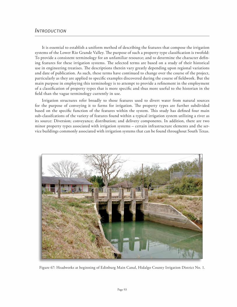
Headworks at beginning of Edinburg Main Canal, Hidalgo County Irrigation District No . 1 .Figure 67:
Page 93
introduCtion
It is essential to establish a uniform method of describing the features that compose the irrigation systems of the Lower Rio Grande Valley . The purpose of such a property type classification is twofold: To provide a consistent terminology for an unfamiliar resource; and to determine the character defin-ing features for these irrigation systems . The selected terms are based on a study of their historical use in engineering treatises . The descriptions therein vary greatly depending upon regional variations and date of publication . As such, these terms have continued to change over the course of the project, particularly as they are applied to specific examples discovered during the course of fieldwork . But the main purpose in employing this terminology is to attempt to provide a refinement in the employment of a classification of property types that is more specific and thus more useful to the historian in the field than the vague terminology currently in use .
Irrigation structures refer broadly to those features used to divert water from natural sources for the purpose of conveying it to farms for irrigation . The property types are further subdivided based on the specific function of the features within the system . This study has defined four main sub-classifcations of the variety of features found within a typical irrigation system utilizing a river as its source: Diversion; conveyance; distribution; and delivery components . In addition, there are two minor property types associated with irrigation systems – certain infrastructure elements and the ser-vice buildings commonly associated with irrigation systems that can be found throughout South Texas .

Page 94
Diversion components move the water from the river source into the irrigation system . Diversion features are most commonly located at the natural source of the system and are often the most com-plex of the engineering works . They include the pumping plants that force and lift water from its source into the conveyance channels, as well as the associated main headworks that control this flow into the canal . Secondary and tertiary lift plants also divert water over natural topographical obstruc-tions, although they are not necessarily near the original source of the irrigation water .
Conveyance components move the water from the source to the farmlands intended for irrigation . These structures form the skeleton of an irrigation system and are an integral feature of its overall design . These water conduits include canals, laterals, pipelines and flumes, as well as resacas and reservoirs that impound water for future distribution .
Distribution components control the movement of the water through the system . These features include both major and minor features such as dams, check gates, head gates and smaller take-out gates, as well as control and measurement features such as weirs and division boxes .
Delivery components deliver the water from the main canals and laterals to its final destination, the agricultural fields . These features are generally located on private land and many are under the control or ownership of individual farms . Delivery features include sub-laterals, tertiary laterals, and privately owned and operated pipelines and standpipes, as well as the gates and other appurtenances associated with the final delivery of water to the fields . As such, there is a duplication of many of the features found in the property sub-types of both conveyance and distribution features . It is func-tion and placement within the overall system, rather than the feature itself, that determines its clas-sification within the property sub-type .
There are several sub-types of properties associated with the infrastructure of maintaining an irrigation system that include roads, bridges, and drainage ditches . Roads and bridges allow access to the canals for routine maintenance as well as access to gates by ditch riders . Seepage ditches catch water that escapes from the irrigation canals and returns it to the irrigation system . Drainage ditches, many of which are operated by drainage districts independent of the irrigation districts, drain excess irrigation water from the fields, including alkalines or other impurities .
Both permanent and temporary features are included in the list of property type descriptions (following page) . Permanent components are generally intended to serve multiple growing seasons, although they may require a great deal of seasonal maintenance . By contrast, temporary features are moved from place to place during each irrigation season and are transitory in nature . These features are very site-specific and are most often located in individual farm fields . Due to the temporal na-ture of these features and their location on private property, it is highly unlikely that it will ever be necessary to evaluate one of these features for NRHP eligibility . A brief description is included merely to further our understanding of the overall functioning of an historic irrigation system .

Property Type Property Sub-type Component Type
Page 95
Irrigation System Diversion Feature Diversion Dam
Irrigation System Diversion Feature Inlet Channel
Irrigation System Diversion Feature Pumphouse 1st Lift Plant
Irrigation System Diversion Feature Pumphouse 2nd Lift Plant
Irrigation System Diversion Feature Pumphouse 3rd Lift Plant
Irrigation System Diversion Feature Pumphouse Pumping station
Irrigation System Diversion Feature Headworks
Irrigation System Diversion Feature Settling basin
Irrigation System Conveyance Feature Canal Main ~ lined or unlined
Irrigation System Conveyance Feature Canal Lateral ~ lined or unlined
Irrigation System Conveyance Feature Canal Sub-lateral
Irrigation System Conveyance Feature Resaca
Irrigation System Conveyance Feature Reservoir
Irrigation System Conveyance Feature Flume Box flumes
Irrigation System Conveyance Feature Flume Pipe flumes
Irrigation System Conveyance Feature Siphon
Character Defining Features of Irrigation Systems in South Texas

Property Type Property Sub-type Component Type
Defining features, contd.
Page 96
Irrigation System Conveyance Feature Culvert Box
Irrigation System Conveyance Feature Culvert Pipe
Irrigation System Conveyance Feature Underground pipeline
Concrete, mortar joints
Irrigation System Conveyance Feature Underground pipeline
Concrete, rubber gasket joints
Irrigation System Conveyance Feature Underground pipeline Plastic pipe
Irrigation System Distribution Feature Gate Check gate
Irrigation System Distribution Feature Gate Head gate
Irrigation System Distribution Feature Gate Take-out gate
Irrigation System Distribution Feature Gate Sand gate
Irrigation System Distribution Feature Gauging shed
Irrigation System Distribution Feature Weir
Irrigation System Distribution Feature Division box
Irrigation System Distribution Feature Division gate
Irrigation System Distribution Feature Standpipe
Irrigation System Distribution Feature Pump stand
Irrigation System Distribution Feature Surge chamber
Irrigation System Distribution Feature Diversion stand
Irrigation System Distribution Feature Vent

Property Type Property Sub-type Feature Type
Defining features, contd.
Page 97
Irrigation System Delivery Feature Canal Sub-lateral
Irrigation System Delivery Feature Temporary conveyance
Furrows, corrugations, border strips, checks
Irrigation System Delivery Feature Underground pipeline Concrete, plastic
Irrigation System Delivery Feature Surface pipe Siphons, poly-pipe
Irrigation System Delivery Feature Spray pipe
Irrigation System Delivery Feature Gate Turn-out gate
Irrigation System Delivery Feature Temporary distribution
Dams ~ canvas, portable steel, earth, straw and earth
Irrigation System Infrastructure Bridge
Irrigation System Infrastructure Road
Irrigation System Infrastructure Drainage Ditch
Irrigation System Infrastructure Seepage Ditch
Irrigation System Infrastructure Levee

Page 98
Irrigation System Office Building District office
Irrigation System Warehouse
Irrigation System Shed
Irrigation System Employee residence
Government Public works Gauging station
Government Public works Dam
Commerce/Recreation Clubhouse
Agricultural Farmstead Residence
Agricultural Farmstead Outbuilding
Agricultural Farmstead Agricultural fieldSpecific type of field (i .e . orchard)
Transportation Railroad depot
Industrial Manufacturing Box factory
Agricultural Processing Food processing plant
Agricultural Processing Cannery
Agricultural Processing Produce packing shed
Agricultural Processing Dehydration plant
Agricultural Processing Cottonseed oil mill
Agricultural Processing Cotton gin
Agricultural Processing Sugar processing plant
Property Type Property Sub-type Building Type Type
Associated Property

Diversion Features

Page 100
diVErsion fEaturEs
The purpose of diversion features is to guide the river water into the main canal of the irrigation system . Traditionally, irrigation systems diverted water from a river simply through the construction of a diversion dam that raised the height of the water sufficiently to divert it into a canal dug at an angle to the river . Due to the height and steepness of the riverbank along the American side of the Rio Grande, it is not possible to directly divert water into a canal . Instead, the water must be “lifted” over the high banks of the river . A pumping plant most efficiently accom-plishes this task, though the earliest efforts probably utilized more primitive methods . Headworks are an essential element of a system, whether the water is diverted directly into a canal or pumped from the river into the canal .
diversion dAms And inlet chAnnels
A diversion dam is constructed at the origin of a main canal or ditch to both divert water from the river into the canal system and to regulate the amount of water entering from the river . It raises the level of the river during times of low water to force water into the ditch while also preventing floodwaters from filling a ditch beyond its capacity . The earliest such dams were simple brush and stone structures constructed diagonally into and across the streambed . Although they tended to be washed away by floods or even high water, they were easily replaced with little expense of funds or labor . Later dams were constructed of timbers, and more commonly, of masonry with foundations laid to bedrock .
In South Texas, irrigation systems used pumps to divert water out of the Rio Grande and into the canals . Before the construction of Falcon Dam, however, diversion dams were sometimes placed below a pumping plant to raise the level of the river during periods of low flow . This insured that the intake pipes remained sufficiently underwater at a depth that would allow the pumps to operate .
Diversion dams are also used below inlet channels . Before flood control, pumping plants often became separated from the Rio Grande after the river changed course after floods . This required the dredging of inlet channels from the new river alignment to the pumping plant . Diversion dams were placed below the inlet channel to divert a sufficient quantity of water into the new channel . There are several examples of pumping plants that require inlet channels to obtain water from the Rio Grande, including Hidalgo County Irrigation District No . 1 and Hidalgo County Irrigation District No . 2 .

View of inlet channel at Rio Grande River, looking west from Figure 68: first lift pumping station, Hidalgo County Irrigation District No . 3 .
View up inlet looking north towards first lift station, Figure 69: Hidalgo County Irrigation District No . 1 .
Page 101

First lift pump station, United Irrigation District .Figure 70:
Page 102
pumping fAcilities
Irrigation of the lower Rio Grande Valley was not possible by a purely gravity flow method, as the river is at a lower elevation than the adjoining land . It is necessary to first “lift” the water up from the river basin . Pumphouses were constructed to house the machinery and equipment necessary to complete this task . These pumphouses are further described by their position along the system . First lift pumphouses are positioned at the Rio Grande River and effect the initial lifting of the river water into the irrigation system . Second lift pumphouses are located at a high ridge and serve to lift the irrigation water over this change in elevation . Third lift pumphouses are located along a subsequent ridge . As the primary purpose of the pumphouse is to protect the pumping equipment, this property type should be considered as a structure to distinguish it from a building (defined by the National Park Service as “created principally to shelter any form of human activity”) .
First Lift Pumphouses
First lift pumphouses (also called first lift pump stations or river pumping plants) are generally located directly on the banks of the Rio Grande River . The actual pumps are located in concrete pits constructed about ten feet below the surface of the ground . Suction pipes, also known as inlet pipes, extend directly into the river and the pumps, powered by engines, lift the water out of the river and into the irrigation system . There are generally two types of pumps; centrifugal pumps which generate a circular motion, and hydraulic pumps that create a vertical motion to move the water . The earliest engines were powered by steam (using wood), and later diesel engines . Today, engines powered by electricity or natural gas are most common .

First lift pumphouse (1953), Hidalgo County Irrigation District No . 19 .Figure 71:
Old first lift pump house (1921) and inlet channel, Figure 72: Hidalgo County Irrigation District No . 3 .
Page 103

Inlet pipes to pumphouse, Figure 73: Cameron County Irrigation District No . 6 .
View of engines, first lift pumphouse, Figure 74: Hidalgo County Irrigation District No . 1 .
Inlet pipes to first lift pumphouse, Hidalgo County Irrigation District No . 1 .Figure 75:
Page 104

Interior view of boiler room, Old Hidalgo First Lift Pumphouse .Figure 76:
Page 105
The location of the first lift pumphouses so close to the river places these buildings at high risk of damage from flooding . Moreover, the change in technology from steam to diesel and finally, to electricity has made their design obsolete for modern purposes . With the rapid expansion of the amount of acreage irrigated in the Valley in the 1960s, it became necessary to expand the pumping capacity of these plants . The older buildings were not always capable of housing the new equipment . As a result, many of these historic-age resources have been abandoned or demolished .
It was not uncommon for the earliest river pumps to be unprotected by any building; this allowed the expensive pumping equipment to be quickly moved to higher ground in case of an impending flood of the Rio Grande River . When intact, first lift pumphouses are generally larger and more elabo-rate in their design than second or third lift pumphouses . Due to the size of the engines required to lift the water from the Rio Grande, these structures tend to be much larger than the second or third lift stations . As they were critical to the initial functioning of an irrigation system, they tend to be the first buildings constructed within an irrigation system . The Mission Revival detailing of the Hidalgo First Lift Pumphouse is an outstanding example . Constructed in 1910, this pumphouse ini-tially used steam engines powering centrifugal pumps to lift the water from the river basin . By 1948, diesel engines were installed . It was not until 1980 that the pumphouse was powered by electricity (it was abandoned in 1983 with the construction of a new pump station downstream) . In 1906, the American Rio Grande Land and Irrigation Company in Mercedes used an electric plant for its first lift pumphouse (demolished) . The first lift pumphouses of Hidalgo County Irrigation District No . 1 and Cameron County Irrigation District No . 6 are extant examples that are still in use .

The Old Hidalgo First Lift Pump house originally featured dual smokestacks (1915) . Figure 77: Source: Brochu, Getting Up Steam: The History of the Hidalgo Pumphouse
The Old Hidalgo First Lift Pumphouse (NRHP, 1995) as it appears today . Figure 78: (Hidalgo Water Improvement District No . 2, 1910) .
Page 106

First lift pumphouse (1922), Cameron County Irrigation District No . 6 .Figure 80:
First lift pumphouse (1927), Hidalgo County Irrigation District No . 1 .Figure 79:
Page 107
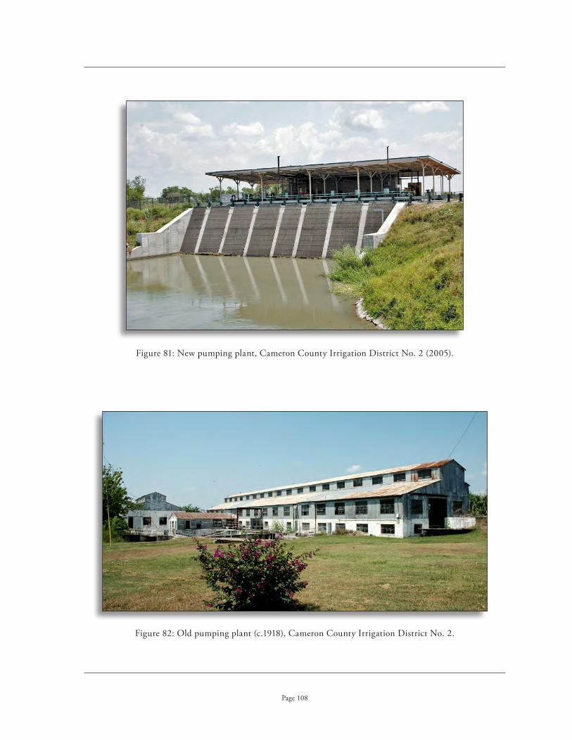
New pumping plant, Cameron County Irrigation District No . 2 (2005) .Figure 81:
Old pumping plant (c .1918), Cameron County Irrigation District No . 2 .Figure 82:
Page 108

This early second lift pump, built of redwood, provided both irrigation and drinking water for Weslaco . Figure 83: Source: Gerhardt and Tamez, Images of America: Weslaco
Page 109
Second Lift Pumphouses
The second lift pumphouse was typically less elaborate in its design and smaller in size, as a fewer number of engines are required in the second lift . Historic-age second lift pumphouses are usually of frame or brick construction with partial or full brick firewalls, although it is not uncommon to find examples constructed of concrete brick or corrugated metal . They feature a rectangular plan with a simple gable roof . Perhaps the most prominent features are the tall, concrete smokestacks and the intake pipes that redistribute the water . With the introduction of modern engines, the smoke-stacks are often demolished .
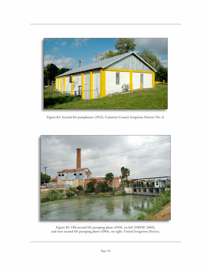
Second lift pumphouse (1922), Cameron County Irrigation District No . 6 .Figure 84:
Old second lift pumping plant (1910), on left (NRHP, 2002), Figure 85: and new second lift pumping plant (1984), on right, United Irrigation District .
Page 110
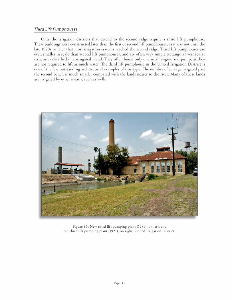
New third lift pumping plant (1989), on left, and Figure 86: old third lift pumping plant (1921), on right, United Irrigation District .
Page 111
Third Lift Pumphouses
Only the irrigation districts that extend to the second ridge require a third lift pumphouse . These buildings were constructed later than the first or second lift pumphouses, as it was not until the late 1920s or later that most irrigation systems reached the second ridge . Third lift pumphouses are even smaller in scale than second lift pumphouses, and are often very simple rectangular vernacular structures sheathed in corrugated metal . They often house only one small engine and pump, as they are not required to lift as much water . The third lift pumphouse in the United Irrigation District is one of the few outstanding architectural examples of this type . The number of acreage irrigated past the second bench is much smaller compared with the lands nearer to the river . Many of these lands are irrigated by other means, such as wells .

Pump No . 3 (1948), Hidalgo County Irrigation District No . 15 .Figure 87:
Pumping shed, Cameron County Irrigation District No . 6 .Figure 88:
Page 112
Pumping Station
Pumping stations are located along main canals, resacas or drainage ditches and lift the water from the canal into an adjacent lateral when they are above the grade of the main canal . While they can be utilized to pump water from the main canal directly into a lateral, they are most commonly used to pump water into a pipeline . Pumping stations house much smaller pumping units than second or third lift pump houses . Due to their small size, they are usually powered by electricity or diesel fuel . Pumping stations can be either fully enclosed in a structure constructed of galvanized metal, concrete block or wood, or they can be housed under an open structure with columns supporting a metal roof . It is not uncommon for such pumping stations to be privately owned and operated .

Diagram of head gates, San Benito Land and Irrigation Company, c .1905 Figure 89: (Cameron County Irrigation District No . 2 .) .
Source: San Benito in the Lower Rio Grande Valley
Page 113
mAin heAdworks (mAin heAd gAte)
The main headworks are placed at the “head” of an irrigation or canal system, or the point at which river water is diverted into the irrigation system . Whereas a head gate is a single structure, the main headworks is a more complex water gate and functions as a regulator for the vast amounts of water being released into the system from the pumping plant . It is generally located at the pumphouse and can extend a hundred feet from the outake . Headworks are commonly arranged in a series of gates, or stalls, operating independently of one another . They may include a spillway back to the stream, a sand trap, and an apparatus for controlling the water flow into the canal . Some headworks include a measuring flume and some method for recordation . In the Lower Rio Grande Valley, the main headworks are located at the point where the water leaves the first lift plant . Smaller headworks are located at subsequent lift plants .
The earliest headworks were constructed of lumber, but were generally subject to the destructive forces of floods . Concrete or iron headworks were later used as a more permanent structure capable of sustaining flood forces . Concrete abutments extending in both directions generally hold the head gate in place . When water is pumped directly into an underground pipeline, the headworks consists of a surge wall . Constructed of a large concrete box, this structure acts as a surge chamber to prevent damage from changes in pressure .
The irrigation system of the San Benito Land and Water Company (later Cameron County Irrigation District No . 2) began as a purely gravity flow system that utilized the resaca system as its main canal . A head gate constructed onto the banks of the Rio Grande provided water directly from the river through eight gates, each 4 feet by 6 feet . The entire structure was constructed of reinforced concrete with dimensions extending 250 feet in length and 22 feet in height . A foun-dation 17 feet wide rested on pilings driven 26 feet below the river bottom . This structure is now incorporated into the foundations of the irrigation system’s first lift plant .

Main headworks, first lift pumphouse, Cameron County Irrigation District No . 6 (1929) .Figure 90:
Main headworks, second lift pumphouse (1922), Cameron County Irrigation District No . 6 .Figure 91:
Page 114

Intersection of new and old main headworks (1910/1984), second lift Figure 92: pumping plant, United Irrigation District .
Detail of new headworks (2005), Hidalgo County Irrigation District No . 3 .Figure 93:
Page 115

Surge box (1953) at river pumping plant, Hidalgo County Irrigation District No . 19 .Figure 94:
Surge wall (1927) at first lift pumping plant, Hidalgo County Irrigation District No . 1 .Figure 95:
Page 116

View across settling basin, Cameron County Irrigation District No . 6 .Figure 96:
Page 117
Settling Basins
Settling basins are small reservoirs located along the conveyance system used to remove the heavy silts that are characteristic of the waters of the Rio Grande River before they are released into the smaller canals of the irrigation system . This component is generally located near the diversion point of the irrigation system . The main canal carries water from the first lift plant into the settling basin where the silt from the river is allowed to settle at the bottom of the reservoir . The main canal is continued at the other end of the settling basin . Since the construction of Falcon Dam in 1954, much of the sediment of the river is contained behind this dam . As a result, this type of component is no longer as essential as it once was in the design of irrigation systems along the Rio Grande . Many of the early settling basins have been abandoned or enlarged for use as storage reservoirs .

Conveyance Features

The fresno scraper (1915) . Figure 97: Source: Knight & Associates
Page 119
ConVEyanCE fEaturEs
The function of conveyance features is to move the water through the irrigation system . The basic principles of hydraulics are essential to understanding the design and function of irrigation systems . In order to deliver water in the most efficient way possible, it is critical to maintain not only a constant flow of water, but also a constant velocity . The design of a canal or ditch is a combination of its bed width and depth, together with the resulting mean velocity .
In its broadest definition, a canal is a man-made channel that delivers water for irrigation purposes by linking an existing river or man-made reservoir with agricultural fields . Although the literature on irrigation systems refers to both canals and ditches, there is no attempt to define the difference between a ditch and a canal . A ditch, however, appears to refer to a narrow and very shal-low canal, usually of earthen construction . It is generally used for small, simple irrigation systems . The terms, however, are commonly used interchangeably .
The earliest irrigation canal systems featured open earthwork canals characterized by a wide canal with low earthen embankments . Early canal construction utilized mule-drawn fresnos, a large scraper that scooped up soil from the ditches and piled it on the edges of the canal for the embankments . Later canals used ditching machinery, such as the New Era Road Machine, which plowed the soil and threw it on a conveyor belt that carried it over the side of the ditch . These early machines were still pulled by horses, but could do the work of 30 men .

Horse-drawn ditching machinery (c .1870) . Figure 98: Source: Newell, Irrigation in the United States
Construction of main canal for the Figure 99: American-Rio Grande Irrigation & Land Company (c .1905) .
Source: Texas Historical Commission Marker Files
Page 120

An early cement lined canal (c .1900) . Figure 100: Source: Newell, Irrigation in the United States
Page 121
The most efficient shape for a canal is a semicircle wherein the width of the ditch at the top is twice its depth in the center . Many earthen ditches, however, were rectangular in shape . The grade of a canal system is essential and should be as uniform as possible throughout . At the turn of the century, the average grade for a main earthen ditch, carrying from 2 to 6 feet of water, was from 1 .5 to 2 .75 feet per mile . The friction on the sides of such earthen ditches is relatively large . In smaller ditches, a steeper grade is required . If the grade is too steep, the erosion of the earthen banks by the increased velocity of the water causes the depth of a ditch to get lower and lower, until it is not possible to obtain water from it . It is important to keep the flow of water near the surface in order to distribute the water to lateral and sub-lateral canals . Yet, if the water flows too slowly, because the grade is too low, the ditch becomes clogged with aquatic weeds and grasses . In the construction of a canal system, it is important to avoid the silting of the canals caused by the erosion of earthen ditches and the deposit of silt and debris by the water from the river source . Silting clogs the canals and prevents the necessary velocity for the conveyance of water .
Canals lined with concrete and other materials, such as brick, significantly reduce water loss from both evaporation and seepage into the earth and through the banks of a canal . Concrete lined canals were described as early as 1902 and were promulgated by the US Department of Agriculture by 1920 . The advantages of lined canals include: decreasing conveyance losses or seepage through the bot-toms and sides, providing against breaks in the canals; preventing weed growth and retarding moss accumulation; decreasing erosion from high velocities; reducing maintenance costs; and increasing the capacity of the canal to convey water . As the smooth channel provides for a more rapid movement of water even on a slight grade, the construction of lined canals often necessitated re-grading the irri-gation system . According to local sources, it appears that many of the canals in the Lower Rio Grande Valley were first lined with concrete beginning in 1927 and 1928 .

Type of Canal Main Canals Lateral Canals Totals
Unlined canal 439 miles 175 miles 614 miles
Lined canal 351 miles 201 miles 552 miles
Unknown 5 miles 297 miles 302 miles
Subtotals 795 miles (open main canals)
673 miles (open lateral canals)
1,468 miles (main and lateral)
canalsPipeline 192 miles 1,755 miles 1,947 miles
Resaca 76 miles 0 miles 76 miles
Totals 1,063 miles (main canals)
2,428 miles (lateral canals)
3,491 miles (main and lateral canals, all types)
Main and Lateral Canals of the Lower Rio Grande Valley
Source: Guy Fipps, P .E . “Potential Water Savings in Irrigated Agriculture for the Rio Grande Planning Region: 2005 Update .” College Station: Texas A&M University, Irrigation Technology Center, 2005
Page 122
Concrete lined canals can be constructed of narrower dimensions than earthen canals as the erosion of the banks is no longer a concern . Their cross-sections are usually of a semi-circular or V-shaped design . The earliest lined canals were constructed by first lining the canal with stones or small boulders and then plastering them with concrete . Later canals were lined with cement only . The bottom and sides of the canal were surfaced with concrete and then a second coating of Portland or hydraulic concrete was applied to a thickness of 3/4 of an inch . Shotcrete, also referred to as gunite, became a popular method for applying concrete during the 1930s . This method involved applying the concrete by spraying it onto the walls of the canal under high pressure .
Today, synthetic materials are often used to line canals . There are a number of different methods employed using a synthetic or plastic lining to prevent seepage . Many districts have experimented with geomembrane linings of canals . Other linings are commonly made from high density poly-ethylene, polypropylene, polyvinyl chloride and other materials such as rubber .
According to a 2005 report by the Irrigation Technology Center at Texas A&M University, main canals of the irrigation districts of the Lower Rio Grande Valley consisted of 795 miles of canals (lined and unlined), 192 miles of pipeline, and 76 miles of resacas . District-owned laterals and sub-laterals included 673 miles of canals and 1,755 miles of pipelines . The width of unlined canals varies greatly in the Valley, with no average width . Widths of earthen main canals can vary from 20 feet to more than 100 feet, even within an individual irrigation structure . The average width of concrete canals varies between 5 and 8 feet for laterals and 18 to 26 feet for main canals .1
1 . Fipps, “Potential Water Savings in Irrigated Agriculture for the Rio Grande Planning Region: 2005 Update”

Resaca del Rancho Viejo is used as an earthen canal branch Figure 101: of the main canal in Cameron County Irrigation District No. 2.
Earthen main canal, Figure 102: Cameron County Irrigation District No. 2.
Earthen Edinburg Main Canal (1912/1926), Figure 103: Hidalgo County Irrigation District No. 1.
Page 123
Earthen Canals

Concrete lined main canal (c .1930) at second lift pumping plant, United Irrigation District .Figure 104:
Concrete lined lateral canal (1937), Figure 105: Cameron County Irrigation District No . 6 .
Concrete lined canal (1927), Figure 106: Hidalgo County Irrigation District No . 1 .
Page 124
Concrete Lined Canals

Brick lined canal (1938), Figure 107: Cameron County Irrigation District No . 6 .
Detail of brick lined canal (1938), Figure 108: Cameron County Irrigation District No . 6 .
Brick lined lateral canal (1937), Figure 109: Cameron County Irrigation District No . 6 .
Page 125
Brick Lined Canals

Main canal for Cameron County Irrigation District No . 5, as it appeared c .1910 . Figure 110: Source: Runyon Photograph Collection
High Line Canal, Figure 111: Cameron County Irrigation District No . 2 .
Page 126
mAin cAnAls
The main canal carries water from the primary source, the river, and distributes it throughout the irrigation system . It conveys water to the lateral canals that extend from the main canal . Direct irrigation onto the fields is generally not permitted from the main canal, though exceptions can be found . In the Lower Rio Grande Valley, these main canals generally run on a south to north axis along the western edge of the irrigation district . This placement allows for a distribution of water across the natural topography of the land before it is drained to the east and, eventually, into the Gulf . The earliest main canals are wide earthen channels with low embankments . Because of problems with seepage, however, many canals were lined with concrete or placed in underground pipelines . Water is distributed by gravity flow and the canals must be able to deliver the water to adjacent lands; thus, the canals are generally placed above grade (whereas drainage ditches will be placed well below grade) . Where canals are below grade from the adjacent agricultural fields, small pumps are used to convey the water from the canal . Main canals are primarily distinguished by their placement in the design of the overall system, as they link the river to the rest of the conveyance system . But they are commonly the widest and deepest canals within an irrigation structure . It is not uncommon for a main canal, however, to narrow as it travels away from the river source .
high line cAnAl
This is a term applied to canals that distribute water to land too high in elevation to be watered by gravity flow . High line canals are typically filled with water by pumps and it may be neces-sary to pump the water out of the canals and into the subsequent conveyance structures .

Northwest view of main canal (c.1914), Figure 112: Cameron County Irrigation District No. 6.
Main canal (1960) at first lift pumping plant, United Irrigation District.Figure 113:
Page 127

Main canal (c .1907), Hidalgo County Irrigation District No . 3 .Figure 114:
Edinburg Main Canal (1926) at first check gate, Los Ebanos Road, Figure 115: Hidalgo County Irrigation District No . 1 .
Page 128

Lateral being placed in underground pipeline along Trosper Road, United Irrigation District .Figure 116:
Page 129
lAterAl cAnAls
Lateral canals, or supply canals, transport water from the main canal to the wider geographic area covered by the agricultural fields and served by the irrigation system . The term “lateral” can refer to both the secondary and tertiary network of irrigation canals that carry water from the main canals to the field turnouts . Secondary laterals (or sub-laterals) are most commonly tapped by individual farmers to water their fields . Tertiary laterals refer to either small laterals within very large irrigation systems or smaller laterals on privately owned land .
Lateral canals need to be large enough to carry at least double the average amount of water required since the water supply can vary greatly in a season . The bottom of the lateral canal must be higher than the surface of the ground in order to service the fields through gravity alone . Otherwise, small pumps are required to elevate the water into the fields from the canal . Laterals can be either earthen or concrete lined canals, although lined canals are most common in the Valley for this type of conveyance canal . Many laterals are now placed in underground pipelines, their presence only visible by the presence of standpipes .

Lateral (1929/1931), Hidalgo County Irrigation District No . 3 .Figure 117:
Bodine Lateral, Hidalgo County Irrigation District No . 19 .Figure 118:
Page 130

Brick lined Stub-Tandy Lateral (1938), adjacent to Tandy Road, Figure 119: Cameron County Irrigation District No . 6 .
Geo-membrane lined lateral canal (2005) off FM 2128, Figure 120: Hidalgo County Irrigation District No . 1 .
Page 131

Intersection of Resaca de Los Fresnos and Resaca del Rancho Viejo, Figure 121: Cameron County Irrigation District No . 2 .
Page 132
resAcAs
Resacas are ox bow lakes or former river channels . Some irrigation districts use these resacas as both water storage and water channels (canals), incorporating a natural feature into the irrigation system . The use of resacas is most prevalent in the irrigation systems in Cameron County . Cameron County Irrigation District No . 2 (San Benito) was originally designed to utilize the Resaca de los Fresnos as the main canal .

Resaca at San Benito, Cameron County Irrigation District No . 2 .Figure 122:
Resaca at Lift Station No . 2, Cameron County Irrigation District No . 6 .Figure 123:
Page 133

Page 134
Edinburg Lake west of Seminary Road, Hidalgo County Irrigation District No . 15 .Figure 124:
reservoirs
Reservoirs function in several ways, depending upon their location within the design of the system . These structures can act as a settling basin to remove the heavy silts that are characteristic of the waters of the Rio Grande River before they are released into the irrigation system . Before the construction of Falcon Dam, reservoirs stored water for periods of drought when the river flows became too low for pumping . During these periods, the river levels actually dropped below the level of the inlet pipes at the pumping plants . Reservoirs can also function as a way to main-tain pressure within the gravity flow canal system . Following the devastating drought of the 1950s, many of the irrigation districts either constructed new reservoirs or enlarged existing ones for future water storage needs .

Wooden flume across resaca (c .1920s) Figure 125: Source: Watson, The Lower Rio Grande Valley of Texas and Its Builders
Page 135
flumes
Flumes are fully or partially enclosed structures used to convey water over depressions, such as drainage ditches or resacas . Flumes are most commonly semi-circular, V-shaped, or box-like in shape, and constructed of wood, metal or concrete . Due to the weight of the water, these structures must be narrower than the canals they serve, resulting in a constriction of the water flow . Furthermore, the materials used in their construction (particularly metal and wood) provide less hydraulic friction than earthen or canal walls . The narrower dimensions and the construction materials result in a much faster water flow through the flume, with greater turbulence . Flumes commonly include both headworks and tailworks to provide a transition between the slower moving water of the canal and the faster velocities within the flume . Headworks channel the water into the flume and commonly include a concrete apron to prevent erosion of the canal at this point . Tailworks also feature a concrete apron, usually a larger such area, to allow the turbulent water to settle before it continues into the canal .
Flumes are supported on trestles constructed of wood or concrete . Wood flumes are generally square or box-like in shape (box flumes) and tend to deteriorate rapidly . Concrete flumes quickly replaced the use of wood, and generally utilized the same shape . These flumes, open at the top, are reinforced with concrete bars placed across the width of the flume for its entire length . Iron and steel flumes, semi-circular or entirely enclosed, came into common use by the turn of the century . These flumes appear to be raised pipelines on trestles, but obviously connect irrigation canals .
Full-round flumes (or pipe flumes) refer to elevated pipelines constructed of sheet metal or corrugated pipes, generally carried on trestles of wood or concrete . These flumes are totally enclosed . Modern iron or steel pipe can support the water for longer spans than other materials, particularly wood .

Box flume at floodway (2004), Mission Inlet, United Irrigation Dis-Figure 126: trict .
Box flume (1936/1998), Cameron County Irrigation District No . 6 .Figure 127:
Page 136

Full-round flume (c .1990) from Lake Edinburg Figure 128: to main canal, Santa Cruz Irrigation District No . 15 .
Flume over main floodway channel (1984), Hidalgo County Irrigation District No . 3 .Figure 129:
Page 137

Siphon at Samuelson Canal (c .1985), Figure 130: Hidalgo County Irrigation District No . 19 .
Siphon (c .1930) under road, Hidalgo County Irrigation District No . 1 .Figure 131:
Page 138
siphons
Siphons convey the water underground, generally when it is necessary to bypass an obstacle such as a road, floodway, or another canal . The water is placed under pressure, either through the design of the siphon or by means of a pump, to push the water back into the gravity system . Early siphon construction utilized pipes of iron or steel, as the water was under pressure . Today, concrete is the most common material used in the construction of such components .

Concrete pipe culvert, Cameron County Irrigation District No . 6 .Figure 132:
Siphon on Bryan Canal Main Canal, United Irrigation District .Figure 133:
Page 139
culverts
Culverts are underground passageways or channels covered with fill and are commonly used under roads or railroads . Commonly constructed of concrete pipe permanently set into the ground, modern variations utilize corrugated metal pipes or concrete box constructions .

Cross section, 19th century stave pipe . Figure 134: Source: Wilcox, Irrigation Farming
Side view, 19th century stave pipe . Figure 135: Source: Wilcox, Irrigation Farming
Page 140
underground pipelines
Many types of irrigation distribution systems are actually hidden underground and it is difficult to ascertain if these are of historic-age without archival research . The presence of underground pipe-lines can be determined by the existence of standpipes or by consulting the maps of the irrigation district . Although many of these underground pipelines are of historic age, they have probably received numerous repairs over the years including partial replacement with modern materials .
Wooden stave pipes for low pressures and large diameters were often recommended for use in the late nineteenth century . Formed of longitudinal staves braced with iron or steel bands, they were joined together with thin metal tongues inserted between them . Sheet metal pipes, a techno-logical innovation of the California gold rush, eventually were introduced for irrigation purposes . Both wrought iron and steel pipes were available by the turn of the century . Wrought iron, formed from sheets that were rolled and riveted, was more rigid than the steel pipes and less likely to be damaged . Steel was preferred for its smooth surface and use under high pressure . Both types of pipes were treated with an asphalt coating to resist rusting . By the end of the nineteenth century, corrugated metal pipe became common, with the corrugations reinforcing the structural strength of the mate-rial . Vitrified clay pipe and cement pipe were also commonly employed by the turn of the century . These came in 2 foot lengths . Cement pipes, however, were subject to leaks and not expected to last more than eight years .

Laying concrete pipe . Figure 136: Source: Loving, Concrete Pipe for
Irrigation and Drainage
Diagram of underground pipeline (c .1935) . Figure 137: Source: Loving, Concrete Pipe for Irrigation and Drainage
Page 141
Cement pipe was first used for irrigation around 1890 in California, although it did not become common in the Lower Rio Grande Valley until the late 1920s . The first concrete pipe was installed in the Mercedes Irrigation District in 1924 .2 This pipe was installed with mortar joints . Concrete pipe continues to be popular for water conservation purposes as the water losses in earthen channels can vary from 10% to 60% and averages 35% . Furthermore, the use of concrete pipelines provides for improved control over the distribution of irrigation water . Contemporary pipelines are constructed of reinforced concrete with rubber gasketed joints . This type of join gives them a distinct bell-and-spigot profile at the joint . Polyvinyl chloride (PVC) pipe was first used in the 1960s . In recent decades, high density polyethylene pipe (HDPE) and fiberglass reinforced polymer pipe has been introduced .
As water can travel at a velocity of 5 feet per second through a section of 12 feet of pipe, the sudden stoppage of this water by an obstruction or a sudden gate closure can result in the explo-sion of the pipe from the resulting change in pressure . This ef-fect is known as “water hammer .” To avoid the possibilities of a sudden change in water pressure, pipelines are built in straight lines and on as uniform grade as possible to prevent a build-up of silt and standing water in the pipes . In addition, a number of different types of vertical structures, commonly known as stand-pipes, are utilized at the points that commonly might develop such excessive pressure . These structures, open at the top, act as air traps (or, air vents, in some cases) and provide a cushion to absorb the force of moving water to prevent damage to the system . These vertical structures are also used for the installation of gates to control the distribution of water throughout the pipeline system .
2 . Loving, Concrete Pipe for Irrigation and Drainage, 1939, 74

Curry Main Canal (underground pipeline) adjacent to drainage ditch, Figure 138: south of Curry Avenue, Hidalgo County Irrigation District No . 1 .
Initial construction of Curry Main Canal project in 2004 . Figure 139: Source: Photo collection, Hidalgo County Irrigation District No . 1
Page 142

Distribution Features

Women enjoying an afternoon Figure 140: sitting on a check gate on the Edinburg Canal .
Source: Museum of South Texas History, Edinburg
Page 144
distriBution fEaturEs
Distribution features control the movement of the water through the irrigation system . These components include a multitude of different types of features, such as gates, as well as measurement features such as weirs and division boxes . Underground pipelines also contain distribution features such as stand pipes, pump stands, diversion stands and surge chambers .
check gAte
A check gate is placed across a canal to raise the level of the wa-ter in the canal in order to divert it into a lateral upstream from the check gate . The check gate spans the entire width of the canal . Unlike smaller head gates and turn-out gates that are manufactured to standard sizes, check gates must be engineered to their spe-cific placement along a canal . These can be of a simple design in wood or metal (wrought iron or steel), typically with a concrete superstructure . Wood check gates were constructed in a single-wing design that extended across the channel or a double wing design that formed a box shape to control larger flows of water (1920s and 1930s) . Due to the destructive nature of water on wood, it would be uncommon to find gates constructed of historic wood; but wood was commonly replaced as needed .
The most common type of check gate is a lift gate set in an iron or metal frame with grooves . The gate is manu-ally lifted with a turn-wheel . At check gates in large canals where the water fluctuates, it was common to place flashboards at the bottom of the gate over which the water must first pass before entering the smaller canal . This insured an adequate velocity of the water before it entered a smaller channel . A screw-lift gate is designed to operate under higher pressure . It can be opened and closed slowly so that the volume of water can be carefully regulated . A slide gate is designed to slide open, thus its name, and can generally be stopped open in any position . It is used under moderate pressure . Many irrigation districts are introducing modern check gates due to the importance of regulating waterflow .

Diagram of single-wing wooden check gate (1932) . Figure 141: Source: Israelsen, Irrigation Principles and Practices
Cross section of slide gate (1902) . Figure 142: Source: Israelsen, Irrigation Principles and Practices
Page 145

Motorized check gate, Cameron County Irrigation District No . 2 .Figure 143:
Check gate (1931) near State Fish Hatchery, Figure 144: Cameron County Irrigation District No . 6 .
Page 146

Check Gate No . 4 (1975) on Granjeno Canal along Levee Road, Figure 145: near new International Bridge, Hidalgo County Irrigation District No . 19 .
Old check gate north of Pump Station 13, Hidalgo County Irrigation District No . 15 .Figure 146:
Page 147

Electronic radial check gate (2007), United Irrigation District .Figure 147:
Electronic checkgate (2004) on Edinburg Main Canal, Figure 148: Los Ebanos Road, Hidalgo County Irrigation District No . 1 .
Page 148

Head gate on Stub Canal, Cameron County Irrigation District No . 6 .Figure 149:
Page 149
heAd gAte
A head gate is a single structure controlling the water flow into the entrance of a canal . It is most commonly used to refer to a gate controlling a lateral turnout from a main canal, particularly a primary lateral . The head gate shuts off the ditch when it is not in use, thus preventing unauthorized water flow . It also keeps out excess water and debris . The earliest head gates were built of wood, with larger gates constructed of several leafs of wood bolted together with a steel strap . A threaded steel shaft with a wheel at the top allowed the manual operation of the gate along wooden or metal slots . Round steel gates, cast in one piece, were more common for smaller gates . They were used, however, for head gates as well, on a larger scale .

Head gate to lateral, Cameron County Irrigation District No . 2 .Figure 150:
Solar powered, radial head gates (2007) awaiting installation in Figure 151: Cameron County Irrigation District No . 2 .
Page 150

Modern slide gate Figure 153: (c .1950), Cameron County Irrigation District No . 6 .
Iron radial steel gate (c .1895) . Figure 152: Source: Wilcox, Irrigation Farming
Page 151
The take-out gate or turn-out gate is part of the individual farmer’s diversion works and functions in a similar manner to the head gate at the main channel . This gate admits a sufficient amount of water into a small lateral or field ditch, while simultaneously preventing an excessive quantity from entering . The design of take-out gates can be identical to that of head gates . It is rather the positioning of the gate within the overall system that distinguishes them from head gates .
The take-out gate is manually lifted with a turn-wheel . Radial steel gates, cast in one piece, are typical for this type of gate . It is not uncommon, however, to see a small cast iron or metal lift gate set in an iron or metal frame with grooves (slide gate) . It is common for the take-out gate to lead into a small section of pipe to protect the canal from erosion at this point . Pipes and culverts are also commonly used as take-out gates, particularly for relieving small amounts of water from large canals .
tAke-out gAte or turn-out gAte

Gauging stand, Cameron Irrigation District No . 6 .Figure 154:
Page 152
sAnd gAte
A sand gate is a device which traps silt, sand, and other debris from waters drawn from the river and prevents it from entering the irrigation canal . These devices vary greatly in their design and are often incorporated into the design of the head gate . The Rio Grande transports a large volume of earth, necessitating the cleaning of canals at short intervals even with the installation of devices such as sand gates . As sand gates are generally located at the bottom of the canal, they may not be visible to the observer .
gAuging shed
Located along the main canal near the diversion point, these small, corrugated metal sheds are placed either on the banks of the canal or on stilts within the canal . They contained equipment used to measure and record the f low of water in the canal in order to gauge the amount of water being pumped from the river . The actual measuring devices were strung across the canal on a rope . As each irrigation district holds water rights only to a certain number of acre feet of water annually, it is important to be able to track how much water is actually pumped from the river . These devices are no longer used, being supplanted by more modern and dependable methods for measuring water (generally, a modern weir) . This type of pumping shed, however, sometimes survives along the banks of the canal .

Check weir and drop (c .1900) . Figure 155: Source: Newell, Irrigation in the United States
Page 153
weirs
A weir is a small dam constructed so that the water passes either over it or through a section of it with a decided or specific fall . Weirs can be used for two purposes . They can be used to allow water to drop along a steep grade without damaging the canal from the force of the water; and weirs are com-monly used for the purpose of determining the velocity of the water (generally measured in standard miner’s inch) . This type of structure is often incorporated into the construction of an existing dams .
The weir may be either totally submerged, or its sides and ends may project above the water as it narrows the channel . The flow of water is partially stilled just above the weir so the water flows gently and with a uniform current to its edge . On the lower side of the weir, the water encounters a free fall, where the velocity of the water is measured . By referring to standard tables of measurements, based on the size of the weir, one can ascertain the velocity of the flow of the stream with an error of only 1% to 2% . There are generally two main types of weirs, sharp-crested or flat-crested . Although early weirs were constructed of wood, most weirs are constructed of masonry or concrete .
Within irrigation systems, it was common to set weirs within flumes as they were usually less likely to be obstructed by weeds and other debris . The most commonly used weir within a flume is the rect-angular weir, with a small rectangular opening set at the top to regulate the amount of water that can escape . The trapezoidal or Cippoletti weir, however, was also used . This type of weir utilized a trapezoidal-shaped opening wherein the rectangular opening had sloped edges . The advantage of such a weir was in the ease of computing the velocity . Weirs were also set within the irrigation canals themselves with the height of the water noted periodically with a gauge set behind the crest or fall of the water to record the water heights .

Lyman rectangular weir (1932) . Figure 156: Source: Israelsen, Irrigation Principles and Practices
Trapezoidal or Cippoletti weir (1902) . Figure 157: Source: Newell, Irrigation in the United States
Page 154

Weir on main canal, Cameron County Irrigation District No . 6Figure 158:
Drop weir, Hidalgo County Irrigation District No . 1 .Figure 159:
Page 155

Proportional division box (1932) . Figure 160: Source: Israelsen, Irrigation Principles and Practices
Concrete division box (1932) . Figure 161: Source: Israelsen, Irrigation Principles and Practices
Page 156
division boxes
Division boxes, also referred to as distribution boxes, divide the flow of water within an irriga-tion canal based on a proportional system rather than an exact measuring system . These are probably no longer in use due to modern methods of measuring flow that allow for a more exact distribution of irrigation water . Constructed of either metal, wood or concrete, these box-like devices had simple, movable partitions that would move the flow of water from a lateral canal into a sub-lateral canal in a precise manner .

Regulator, another type of measuring device, near head of canal (c .1900) . Figure 162: Source: Newell, Irrigation in the United States
Concrete division box, Cameron County Irrigation District No . 6 .Figure 163:
Page 157

Division gate, Cameron County Irrigation District No . 2 .Figure 164:
Division gate, Santa Cruz Irrigation District No . 15 .Figure 165:
Page 158
Division Gate
A division gate divides the flow of water between a main canal and a major lateral or between two main laterals . A division gate is essentially two (or more) check gates placed at the intersection of the canals, generally at right angles to one another .

Early concrete standpipe (c.1935). Figure 166: Source: Loving, Concrete Pipe for Irrigation and Drainage
Installation of 8" standpipes to control water flow into furrows (c.1935). Figure 167: Source: Loving, Concrete Pipe for Irrigation and Drainage
Page 159
StandpipeS
The presence of standpipes (also commonly known as vertical structures) indicate the location of underground pipelines. Basically, a standpipe is any vertical structure constructed of concrete (a water tower is a type of standpipe). There are a number of different types of standpipes and many serve multiple purposes. One important purpose is to prevent excessive pressure from building in the pipeline that can result from trapped air and water hammer. Standpipes also contain gates for controlling and distributing water, as well as valves for applying water to fields.
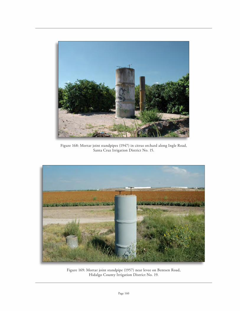
Mortar joint standpipes (1947) in citrus orchard along Ingle Road, Figure 168: Santa Cruz Irrigation District No . 15 .
Mortar joint standpipe (1957) near levee on Bentsen Road, Figure 169: Hidalgo County Irrigation District No . 19 .
Page 160

Row of mortar joint standpipes (1994), Figure 170: FM 494, Hidalgo County Irrigation District No . 19 .
Gasket joint standpipe (1989) off Figure 171: Mile 2 North Road, United Irrigation District .
Mortar joint standpipe (1960s) on Figure 172: Glasscock at Fair Oaks, United Irrigation District .
Page 161

Pump stand on left, with detail of flexible coupling on right (1939) . Figure 173: Source: Loving, Concrete Pipe for Irrigation and Drainage
Pump stand adjacent to underground pipeline, FM 803, Figure 174: Old Cameron County Irrigation District No . 13 .
Page 162
pump stAnds
Water is often diverted into a pipeline from a canal by pumping the water from the canal using small pumps . Pump stands are the vertical structures that are located adjacent to the pumping stations (that contain the pumps and engines) . These structures receive the water, and if it is necessary to divert it in different directions, they also act as diversion boxes with multiple gates . They are connected to the pumping station with a metal or plastic pipe that is connected with a flexible coupling to absorb vibration from the motor .

Surge chamber (1948) near Pump No . 3, Figure 175: Santa Cruz Irrigation District No . 15 .
Page 163
surge chAmbers
Surge chambers are also located adjacent to a pumping station, but are used when pumping directly into a pipeline that is built on a rising grade . They are characterized by a capped lid of reinforced concrete, into which is fit a smaller diameter concrete or metal pipe that commonly extends two feet above the hydraulic grade line .

Cross section of diversion Figure 176: stand and underground pipeline .
Source: Loving, Concrete Pipe for Irrigation and Drainage
Diversion stand (1962) to Bodine Lateral along FM 494, Figure 177: Hidalgo County Irrigation District No . 19 .
Page 164
diversion stAnds
Diversion standpipes are perhaps one of the more common types of standpipes . They are used to divert water from a main pipeline to one or more lateral pipelines, as well as to provide a change of direction in any pipeline . Gates are installed to control and divert the water .

Diversion stand, Cameron County Irrigation District No . 6 .Figure 178:
Diversion well (1948), Santa Cruz Irrigation District No . 15 .Figure 179:
Page 165

Vent pipe (left) adjacent to diversion stand (right), late 1930s, Figure 180: Cameron County Irrigation District No . 6 .
Page 166
vents
Vents are concrete vertical structures installed at gates, at junctions of pipeline, at changes in direction of pipelines, in the summits of pipelines, and at breaks in grade . They should be at least the same diameter of the pipe they serve or greater . They are commonly installed at no more than 500 foot intervals and extend at least 2 feet above the hydraulic grade line . On steep grades, they are used adjacent to gates and also installed downstream . Vents are necessary to prevent excessive pressure from building in the line and resulting in trapped air (water hammer) that can destroy the pipeline . Many of the other types of vertical structures, such as diversion stands, also serve a dual purpose as a vent .

Delivery Features

An early example of flood irrigation . Figure 181: Source: Israelsen, Irrigation Principles and Practices
Page 168
dEliVEry fEaturEs
The purpose of an irrigation system is the delivery of water to the agricultural fields . While many of the same types of conveyance and distribution structures found in an irrigation system are used at the point of distribution on the farmland, these tend to be on a smaller scale due to the smaller amount of water being conveyed to the specific area . In addition, there are some specialized types of structures utilized on the farmlands that are not found within the larger irrigation system . These types of delivery components and distribution structures, because they are much smaller in scale and controlled by individual farmers, tend to undergo a much more rapid change in techno-logical advances than larger scale conveyance and distribution features of the irrigation districts . To remain economically viable, farmers must introduce the most modern methods of irrigating their crops . As a result, few farms continue to utilize the traditional methods of irrigation common in the Lower Rio Grande Valley during the height of the historic period .
There were two main methods of applying irrigation water to fields in the early decades of the twentieth century: flood irrigation and furrow irrigation .
Flood irrigation provides a quick means of providing water to low-lying grain, hay (alfalfa) and rice fields . It is suitable for flat land, but erosion and the accumulation of alkali in the soil became a serious problem . In this type of irrigation, the water must be applied to the high points of the fields to allow for adequate draining . Flood irrigation was sometimes used in orchards, but required more control as the land required careful draining . Border irrigation (also referred to as basin flooding) was developed and became a common method for irrigating orchards . In this procedure, a small embankment was constructed around a group of trees . This area was then flooded with a prescribed measure of water for a period of time .

An early example of furrow irrigation . Figure 182: Source: Israelsen, Irrigation Principles and Practices
Page 169
Furrow irrigation was adopted as the ideal method for watering fields and was quickly adapted to other types of crops . This method used evenly dug furrows, 6 to 12 inches deep, that ran the length of the field or orchard . Water is released into each furrow from the irrigation lateral or sub-lateral . This requires a high level of intensive labor and maintenance, however, to keep the individual furrows flowing . To transfer the water from the lateral to the furrow, farmers used several methods . The simplest was the use of a temporary dam in an irrigation canal to cause an overflow into the furrows . Siphon tubes or pipes were also used by the 1920s to relay water from the canal to the indi-vidual furrows . More modern methods include gated plastic or aluminum pipe, laid on the surface of the field and connected to the canal (with the individual openings or gates releasing water to the furrows) or plastic poly pipe (polyethylene) with holes punched in it at individual furrows .
Sprinkler technology was introduced before World War I, but was not used extensively in the Valley until after World War II . It is a relatively expensive method of applying water through a pres-surized pipeline to overhead sprinkler heads that duplicate rainfall . In some systems, the force of the water also powers a small motor that moves the sprinkler system through the fields or the orchard .
Underground irrigation is becoming increasingly more popular due to the need for water con-servation and its ability to provide water directly to the roots of plants . It is particularly useful for orchards, but is expensive to initially install .

Cross section drawing of an early earthen sub-lateral canal (1902) .Figure 183: Source: Newell, Irrigation in the United States
Early example of a concrete lined sub-lateral canal (c .1910) . Figure 184: Source: Runyon Photograph Collection
Page 170
sub-lAterAl cAnAls
Sub-lateral canals are used within larger irrigation systems and are a smaller distribution canal extending from a lateral canal . Many sub-lateral canals are found on the private farm . The farmer may own the sub-lateral canals or, in some individual cases, the irrigation district may hold an easement on the canal right-of-way . These canals are very shallow and narrow, generally no more than a foot in width . They can be either earthen canals or concrete lined . Many sub-laterals are placed in under-ground pipelines .

View of sub-lateral, Hidalgo County Irrigation District No . 3 .Figure 185:
Farm sub-lateral canal, San Jose Ranch Road, Cameron County Irrigation District No . 2 .Figure 186:
Page 171

Abandoned sub-lateral Figure 187: north of Mile 6 North Road at Trosper, United Irrigation District .
Sub-lateral of Figure 188: Stub-Tandy Lateral Canal, Cameron County Irrigation District No . 6 .
Page 172

Pipeline Figure 189: (c .1957) in orchard, Santa Cruz Irrigation District No . 15 .
Page 173
temporAry conveyAnce structures
These are the smaller ditches used to guide the water to the plants on the farm and covert the land surface of individual farm fields . The contour furrows of a farm field can be used for irrigation if the slopes are carefully controlled . Some furrow-irrigated systems use a small feeder canal lined with concrete placed between the rows . Temporary conveyance structures include furrows, corruga-tions, border strips, and checks .
underground pipelines And stAnd pipes
The conveyance of water under pressure through underground concrete pipes became increas-ingly popular in the late 1940s and 1950s, particularly for the irrigation of orchards . Generally, the water was distributed underground via an 8 inch pipe under pressure . A 16 inch pipe or pressure well permitted the irrigator to insert an iron cut-off gate, thus causing the water to rise in a series of stand pipes located throughout the fields . The water would f low from valve openings in the top of the stand pipes and be distributed to the fields through a variety of different ways .

Farm worker placing siphon tubes in sub-lateral (2007), Figure 190: Cameron County Irrigation District No . 2
Farm worker placing siphon tubes in sub-lateral .Figure 191:
Page 174
surfAce pipes
Surface pipes come in an array of materials . Historically, segmental metal pipe was used for this purpose . Siphon pipes are small rubber tubes placed between the sub-later and each furrow . Capillary action draws the water from the sub-lateral into the fields . Poly (polyethylene) pipe is commonly used today for its ease in moving about the farm, low water loss, low cost, and good surface irrigation ef-ficiency . Used like a “bladder,” it is laid flat on the ground and then connected to a water source, usu-ally from a standpipe . Once it is filled, water is released through punched holes that correspond with furrows in the field .

Surface siphon pipes, Hidalgo County Irrigation District No . 1 .Figure 192:
Surface siphon pipes, Hidalgo County Irrigation District No . 1 .Figure 193:
Page 175

Poly Glick flexible tubing was an early type of surface pipe . Figure 194: Source: Lower Rio Grande Yearbook, 1956
Poly-glick attached to standpipe, distributing irrigation water to field . Figure 195: Source: Lower Rio Grande Yearbook, 1956
Page 176

Poly pipe, Figure 196: Cameron County Irrigation District No . 6 .
View of fields and poly pipe, Cameron County Irrigation District No . 6 .Figure 197:
Page 177

Overhead spray pipes (c .1930) . Figure 198: Source: Watson: The Lower Rio Grande Valley of Texas and Its Builders
Early spray pipes (1932) . Figure 199: Source: Israelsen, Irrigation Principles and Practices
Page 178
sprAy pipes
Spray pipes are a more modern method of distributing water to fields . These pipes actually disperse a fine spray into the air rather than soaking the ground and are considered to be more effec-tive at water conservation . They are more typically found in orchards, but they are not uncommon in vegetable fields .

Turn-out gate on R-8 Canal along Mile 13 Road, Figure 201: Santa Cruz Irrigation District No . 15 .
Early screw gate (c .1935) . Figure 200:
Source: Loving, Concrete Pipe for Irrigation and Drainage
Page 179
gAtes
Turn-out gates from delivery structures on individual farms tend to be very simple easy to operate . Traditionally, these turn-out or cut-off gates (root gates) were of the slide or screw-lift type and were controlled by the individual farmer . Due to the need to accurately record the amount of water use on individual farms, many such gates are now equipped with electronic equip-ment that records the amount of water be-ing used on the farm .

Wooden turn-out gate (rot gate), constructed by Cameron County Figure 202: Irrigation District No . 2 in 2007 .
Page 180

Water diverted into field from furrow by canvas dam (1902) . Figure 203: Source: Newell, Irrigation in the United States
Water distribution from ditch to field employing temporary dam (1902) . Figure 204: Source: Newell, Irrigation in the United States
Page 181
temporAry distribution structures
Farmers used temporary diversion structures to distribute water from the small ditches on their farms to specific areas within their fields . The simplest method was to shovel dirt into the small ditch to form a small earthern dam; but this method was useful only for streams of 1 to 2 cfs . A portable canvas dam was commonly used . It consisted of a sheet of heavy, closely woven canvas suspended from a wooden stick that was hung over the ditch . It was easily carried from place to place as needed and was useful for streams up to 3 cfs . Larger canvas dams were employed for streams up to 5 cfs . Portable steel dams were sometimes used in place of canvas dams . These dams had two wings projecting from a central stake that was placed in the ditch . They were more dif-ficult to carry due to their weight and were not as popular as the canvas dams . Very few of these devices may be seen in use today .

Metal tapoon .Figure 205:
Wooden tapoon .Figure 207:
Early portable Figure 208: metal dam (1932) .
Source: Israelsen, Irrigation Principles and Practices
Metal tapoon .Figure 206:
Figures 149-151: Early drawings of portable dams (1902) .
Source: Newell, Irrigation in the United States
Page 182

Infrastructure

Foot bridge (c .2000) across Bryan Canal, Figure 209: Mile 2 North Road across from district office, United Irrigation District .
Page 184
infrastruCturE
The infrastructure components of an irrigation system refer to those elements and public works features that support the functioning of an irrigation system but do not play a direct role in the delivery of water . An exception to this definition are the levees, which are very broad in their own definition . They are included here, as they play an important role in f lood control and often intersect with irrigation features . Infrastructure components of irrigation systems may contribute to the over-all integrity of an irrigation system . As they play only a supporting role, however, these features will not adversely impact the overall historic integrity of the resource when they lack integrity .
bridges
It was often necessary to cross irrigation canals, either by vehicle or pedestrian way, in order to main-tain and regulate the irrigation system . The construction of bridges across the canals for this purpose can span from the earliest date of the system to the present . These structures tend to be of simple con-struction, usually of wood or concrete . Bridges may also belong to the public transportation system .

Bridge across Resaca de Los Fresnos, Business US 77 in Los Fresnos, Figure 210: Cameron County Irrigation District No . 2 .
Canal bridge (c .1925) near reservoir, Cameron County Irrigation District No . 6 .Figure 211:
Page 185
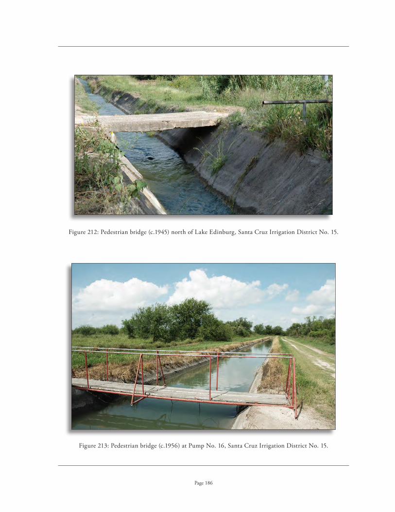
Pedestrian bridge (c .1945) north of Lake Edinburg, Santa Cruz Irrigation District No . 15 .Figure 212:
Pedestrian bridge (c .1956) at Pump No . 16, Santa Cruz Irrigation District No . 15 .Figure 213:
Page 186

Road atop levee at floodgate, United Irrigation District .Figure 214:
Page 187
roAds
Private access roads for maintaining and regulating the irrigation system were constructed after the introduction of the automobile . Before this time, “ditch riders” supervised the canals on horse-back, thus the name for the men responsible for opening and closing the gates along the canal . There were probably few roads constructed until the 1920s . These roads can be either dirt, gravel, or, less commonly, paved .

Road adjacent to Edinburg Main Canal, Hidalgo County Irrigation District No . 1 .Figure 215:
Service road adjacent to new underground siphon Figure 216: across floodway, Hidalgo County Irrigation District No . 3 .
Page 188

Former canal alignment Figure 217: now utilized as drainage ditch, adjacent to McAllen Botanical Gardens, Hidalgo County Irrigation District No . 1 .
Page 189
drAinAge ditches
Drainage ditches allow for the transfer of excess water from agricultural fields to the Gulf of Mexico by way of the natural arroyos and resacas . The earliest irrigation systems did not provide for drainage ditches . The accumulation of alkali, or salts, in the soils of irrigated farmland that was not properly drained quickly led to the practice of installing drainage ditches throughout an irrigation system . Depending upon the alkali content of the soil, it is not uncommon for the drainage ditch of one field to serve as the irrigation ditch for the next field . Due to the topography of South Texas, the drainage ditches run from west to east, emptying into the Gulf of Mexico . With the rapid urbanization of South Texas in the last decades, these drainage ditches now serve multiple functions to drain storm water from urban areas as well .
Most drainage ditches in South Texas are administered by drainage districts whose boards are appointed by the County Commissioners courts . Drainage districts were first authorized by the Texas Legislature in 1905 specifically for the construction of canals, drainage ditches and levees . There is currently one drainage district in Hidalgo County and four drainage districts in Cameron County . Hidalgo County Drainage District No . 1 was established in 1908 . The drainage districts in Cameron County are as follows: Cameron County Drainage District No . 1, established 1910; Cameron County Drainage District No . 2, established 1912 (no longer in operation); Cameron County Drainage District No . 3, established 1912; Cameron County Drainage District No . 4, established 1923; and Cameron County Drainage District No . 5, established 1993 .

Drainage ditch off Curve Road, Hidalgo County Irrigation District No . 1 .Figure 218:
Drainage ditch along Main Canal, Mile 6 North Road, United Irrigation District .Figure 219:
Page 190

Seepage ditch, Cameron Figure 220: County Irrigation District No . 6 .
Early dredge cutting seepage ditch adjacent to canal . Figure 221: Source: Newell, Irrigation in the United States
Page 191
seepAge ditches
Seepage ditches are located adjacent to canals (usually a main canal, to catch water that seeps from these earthen ca-nals . This water is recaptured and placed back into the system . Seepage ditches are placed below the grade of the raised main canal . Seepage ditches, unlike many drainage ditches, are maintained and administered by the irrigation districts .
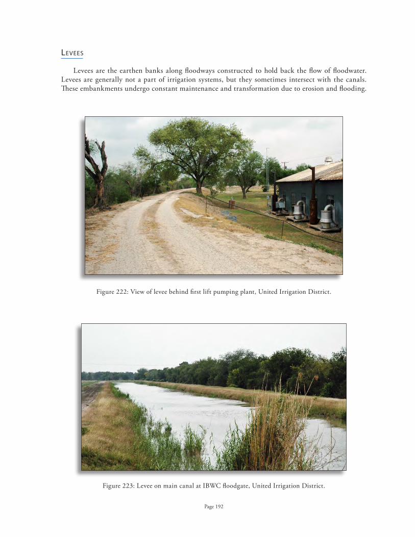
View of levee behind first lift pumping plant, United Irrigation District .Figure 222:
Levee on main canal at IBWC floodgate, United Irrigation District .Figure 223:
Page 192
levees
Levees are the earthen banks along floodways constructed to hold back the flow of floodwater . Levees are generally not a part of irrigation systems, but they sometimes intersect with the canals . These embankments undergo constant maintenance and transformation due to erosion and flooding .

Associated Buildings and Structures

Offices (1974) of Hidalgo County Irrigation District No . 3, 1325 Pecan Street, McAllen .Figure 224:
Page 194
assoCiatEd BuildinGs and struCturEs
There are a number of different types of buildings associated with irrigation systems . These build-ings house activities that are related to the delivery of water, such as the administration of the irriga-tion districts, the housing of employees, and the housing of irrigation equipment . These buildings can be found located either adjacent to the irrigation system or in remote locations . In addition, there are a number of other associated buildings with a connection to the agricultural development of the Lower Rio Grande Valley . This list is not necessarily comprehensive in scope, but the resources listed below are the most common types of buildings and structures that may be encountered which have a potential connection to the agricultural context of the Valley .
irrigAtion compAny/district offices
District offices are not necessarily located directly on the irrigation system . Former offices may be older in age and located nearby the irrigation system . They are generally small office buildings and can vary in style depending upon the date of construction . Because of their close association with the irrigation system, these resources can be considered a discontiguous feature of the system . They may not, however, be readily recognizable, as many of the historic offices are no longer used for their historic purposes . Many of the modern water district offices are less than 50 years of age and are of recent construction .

San Benito Land & Water Company Office Building (c .1910) . Figure 225: Source: Texas Historical Commission Marker Files
Located at 216 North Sam Houston Boulevard, San Benito, Figure 226: the building later served as offices for Cameron County Irrigation District No . 2 .
Page 195

United Irrigation District offices located north of Mission on Mile 2 North Road .Figure 227:
District offices for Hidalgo County Irrigation District No . 19, Figure 228: located in an industrial park on FM 1016, Sharyland .
Page 196

Warehouse (1925) at second lift, Cameron County Irrigation District No . 6 .Figure 229:
Warehouse at district office located off FM 510, San Benito, Figure 230: Cameron County Irrigation District No . 2 .
Page 197
wArehouses
The irrigation districts generally maintain warehouses for equipment used in the maintenance of the irrigation systems . These utilitarian, vernacular structures vary in construction from wood frame to corrugated metal . They may be located adjacent to district offices, pumping stations, or at more remote locations .

Warehouses (c .1945) at district office, Santa Cruz Irrigation District No . 15 .Figure 231:
Warehouse (1953) at pumping plant, Hidalgo County Irrigation District No . 19 .Figure 232:
Page 198

Shed and garage, Cameron County Irrigation District No . 6 .Figure 233:
Barn (c .1921), Old Third Lift Pumping Plant, United Irrigation District .Figure 234:
Page 199
miscellAneous structures
The irrigation companies and water districts utilize different types of structures that serve various purposes . These structures include tool sheds, garages, barns, maintenance buildings and water towers . Most tend to be vernacular structures of utilitarian construction in wood, corrugated metal or cinder block .

Equipment and parking shed, Mile 2 North Road, United Irrigation District offices .Figure 235:
Sheds at first lift pumping plant, Hidalgo County Irrigation District No . 1 .Figure 236:
Page 200

Water tower, old third lift pumping plant, United Irrigation District .Figure 237:
Page 201
It is not uncommon to find a water tower located at the first lift stations at the Rio Grande River as these early pumping plants often represented the earliest source of water for the nearby settlements, as well as for the men who worked at the facility . These water towers vary greatly in both size and form, from simple metal frames to massive brick and concrete structures . By the 1920s, most of the municipalities near the River had installed their own modern systems and no longer had to rely on the river pumping plants for their water supply .

Base of old water tower Figure 238: at first lift station, Cameron County Irrigation District No . 6 .
Remains of water tower, Figure 239: first lift station, Hidalgo County Irrigation District No . 1 .
Page 202
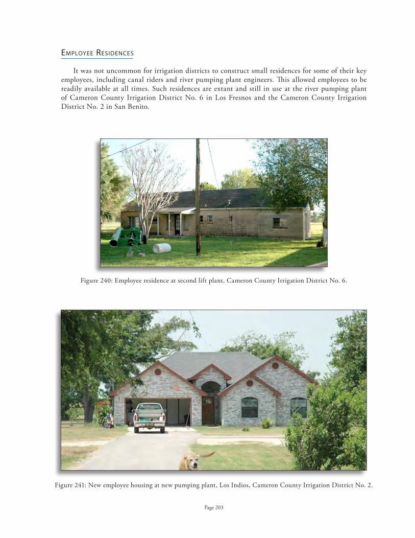
Employee residence at second lift plant, Cameron County Irrigation District No . 6 .Figure 240:
New employee housing at new pumping plant, Los Indios, Cameron County Irrigation District No . 2 .Figure 241:
Page 203
employee residences
It was not uncommon for irrigation districts to construct small residences for some of their key employees, including canal riders and river pumping plant engineers . This allowed employees to be readily available at all times . Such residences are extant and still in use at the river pumping plant of Cameron County Irrigation District No . 6 in Los Fresnos and the Cameron County Irrigation District No . 2 in San Benito .

Employee housing (c .1935) at Figure 242: first lift pumping station, Hidalgo County Irrigation District No . 3 .
Employee housing (c .1900) at pumping plant, Figure 243: Levee Road, Hidalgo County Irrigation District No . 19 .
Page 204

Employee housing (c .1945) behind district office, Santa Cruz Irrigation District No . 15 .Figure 244:
Employee housing (1963) at old third lift pumping plant, United Irrigation District .Figure 245:
Page 205

Gauging station, International Boundary & Water Commission, Figure 246: first lift pump house, Cameron County Irrigation District No . 6 .
Page 206
gAuging stAtions of the internAtionAl boundAry & wAter commission
The International Boundary & Water Commission maintains a number of gauging stations along the river, often located at the river pumping stations . These resources are not directly involved in irrigation efforts, but are associated resources as they reflect the federal government’s involvement in monitoring the river resources .

Falcon Dam under construction . Figure 247: Source: Life Magazine, June, 1953
Page 207
dAms
The International Treaty of 1944 with Mexico specified the construction of three dams along the Rio Grande River for the purposes of irrigation, as this treaty established a system of apportionment of the waters of the river between the two countries . Only two of these dams were constructed: Falcon Dam (1953) and Amistad Dam (1969) . Falcon Dam serves multiple purposes including water storage and conservation, irrigation, flood-control, power, and recreation . This is a compacted, rolled-earth structure with a concrete spillway with six gates . The dam is 26,294 feet long and rises 150 feet above the river bed . Two power plants, one on either side of the border, generate electrical power for each country . The maximum capacity is 4,080,800 acre-feet of water at flood stage . Both dams are admin-istered by the International Boundary and Water Commission .
The construction of two diversion dams took place for the purpose of flood control be-low Falcon Dam . Anzalduas Dam, located southwest of Mission, was completed in 1960 . Constructed primarily to prevent flooding by diverting water into the Arroyo Colorado, this dam also diverts water into the Anzalduas Canal on the Mexican side for irrigation purposes . The Retamal Dam, located south of Weslaco, was constructed in 1973 and lacks any storage capaci-ties for flood waters . Any floodwaters exceeding 20,000 dfs are diverted into the Retamal Floodway in Mexico .

Falcon Dam (completed 1954) is administered by Figure 248: the International Boundary and Water Commission .
Construction of Anzalduas Dam was completed in 1960 .Figure 249:
Page 208

Delta Lake Clubhouse located in Raymondville (c .1910, demolished) . Figure 250: Source: Delta Orchards Company, Lands and Orchards in the Famous Lower Valley of the Rio Grande
Page 209
clubhouses
The early private irrigation companies were often associated with land development compa-nies through parallel boards of directors . These land companies actively promoted the sale of 20 to 80 acre farm plots, particularly focusing their efforts on Midwesterner farmers . Through land excur-sions, these companies either subsidized or wholly paid for potential buyers to travel by rail to South Texas and tour model irrigated farms and the irrigation facilities . During their stay in the valley, visitors resided at clubhouses built specifically for this purpose . These clubhouses can vary greatly in their form and can only be identified through archival research as they are not located on the irrigation system . The Spanish Revival style was very popular for this building type as it reflected the local culture . These buildings tend to be monumental in scale, often encompassing more than 10,000 square feet . It was common for clubhouses to be sited on resacas and to fea-ture large bathhouses . These buildings are well-documented through photographs of land parties, who are often shown standing in front of the clubhouse .
The Shary House once served as a Clubhouse for the Rio Grande Development Company be-fore its conversion into a private residence for John Shary . The clubhouse for the Llano Grande Plantation Company is extant (Progreso) as a private residence . It is not known how many of these resources survive today as many of these clubhouses were converted into palatial residences .
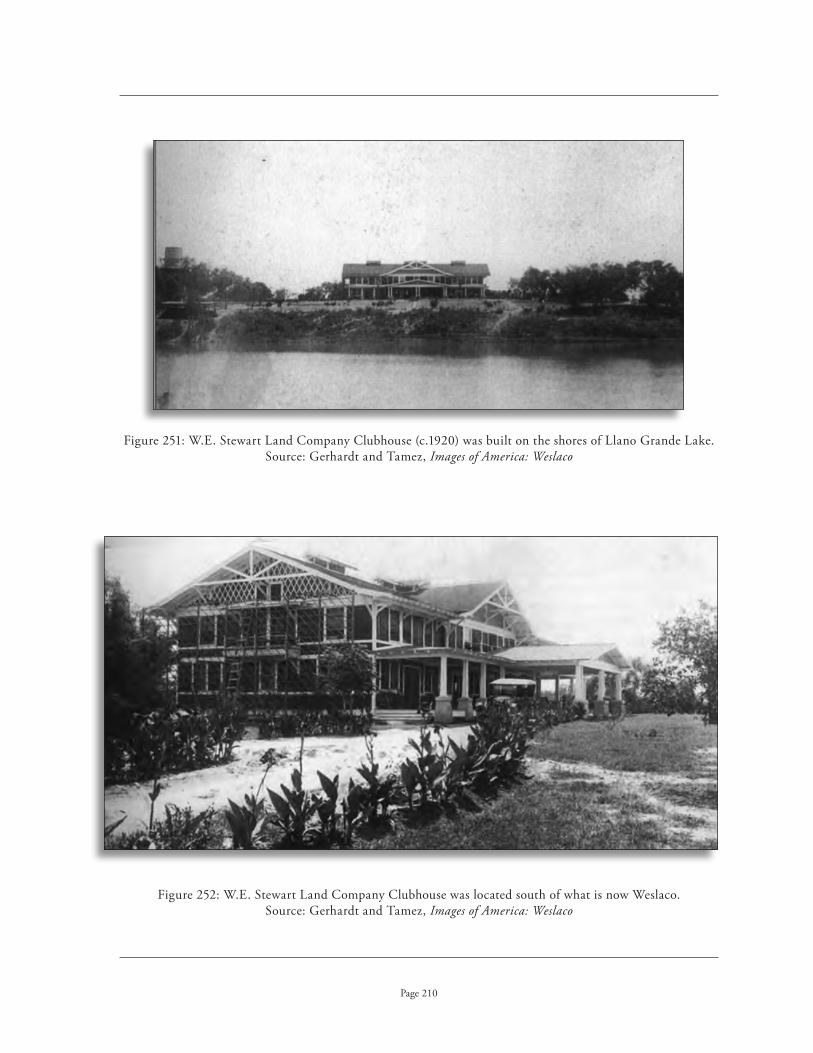
W .E . Stewart Land Company Clubhouse (c .1920) was built on the shores of Llano Grande Lake . Figure 251: Source: Gerhardt and Tamez, Images of America: Weslaco
W .E . Stewart Land Company Clubhouse was located south of what is now Weslaco . Figure 252: Source: Gerhardt and Tamez, Images of America: Weslaco
Page 210

Early photograph of Shary Lake Clubhouse (c .1920) near McAllen . Figure 253: Source: Robert Runyon Photograph Collection
The Shary Clubhouse, located at what is now known as Sharyland, Figure 254: is currently open to public tours of the property .
Page 211

Abandoned farmstead in Santa Cruz Gardens, Hidalgo County .Figure 255:
Page 212
fArmsteAds, outbuildings, AgriculturAl fields
Numerous farmsteads across the landscape are associated with the irrigation system . In South Texas, many of these farms featured bungalows with Arts and Crafts detailing set in lush, tropical landscapes . Such farmsteads commonly included outbuildings for housing farm equipment . But it is the agricultural fields of these farmsteads that were the end destination of the water conveyed through the irrigation system . The presence of the conveyance, diversion and distribution struc-tures on the individual farmstead is of importance when considering their association with the irrigation structure .

Abandoned farmstead along FM 1846, Cameron County .Figure 256:
View of agricultural fields with McAllen in background, Hidalgo County .Figure 257:
Page 213

The old Southern Pacific Railroad Depot in McAllen opened for service in August 1927 .Figure 258:
The Southern Pacific Railroad Depot (1927) in Edinburg, Figure 259: currently serves as the Edinburg Chamber of Commerce Visitor Information Center .
Page 214
rAilroAd depot
The arrival of the railroad in 1904 supplied the transportation to markets necessary for the commercial agricultural development of the Lower Rio Grande Valley . The freight and passenger depots were often the first buildings constructed in the newly established towns along the railway line in the Valley . Many of the larger depots reflect the cultural setting of the Valley in their use of a Mission Revival style or the incorporation of Spanish Revival features .

The Texsun plant, located in Weslaco, was the world’s largest grapefruit processor . Figure 260: Source: Gerhardt and Tamez, Images of America: Weslaco
This former food processing plant now houses Williamson Dickie Figure 261: Manufacturers, Business 83 at Nevada Street, Weslaco .
Page 215
food processing plAnt
This type of processing plant only became common in the Lower Rio Grande Valley after World War II . As a vernacular industrial building type, they are constructed of utilitarian materials including brick, concrete block and corrugated metal . These plants often were later used to serve other purposes and may not be recognizable based on form alone . They are generally located along the railroad tracks .

Crest Fruit Company (originally Alamo Fruit Company), Business 83, Alamo .Figure 262:
View of Crest Fruit Company looking northwest across Business 83 and railroad tracks .Figure 263:
Page 216
cAnnery
Canneries are very similar in type to food processing plants . An industrial building type, they are generally large, rectangular building forms constructed of a wide variety of materials including brick, concrete block and even corrugated metal and wood . These buildings are most commonly located adjacent to the railroad tracks for ease in shipping to additional points .

Donna Citrus Association packing shed (c .1935) . Figure 264: Source: Tamez, Images of America: Weslaco
Produce packing shed located north of railroad tracks, Business 83, San Juan .Figure 265:
Page 217
produce pAcking sheds
Produce packing sheds are found almost exclusively along the railroad tracks . These simple ver-nacular buildings tend to be an open, shed-type form to provide maximum circulation . Corrugated metal walls and roofs appear to be the most common building material .

Cotton gin, Brownsville, 1920 . Figure 266: Source: Robert Runyon Photograph Collection
Cotton gin located off Business 83 at Garza Street, Weslaco .Figure 267:
Page 218
cot ton gin
The basic purpose of cotton gins is to separate the cotton fiber from the seeds . Robert Munger, of Mexia, invented the “system” method of ginning in the 1880s, mechanizing the entire process of separating, cleaning, and baling cotton, using multiple gin stands . His system used steam engines for power and the gins were generally tall, multi-story, wood-framed buildings; the term cotton “gin” is short for cotton “engine .” Diesel engines became popular after World War I . By the 1930s, it was common to see cotton gins sheathed in corrugated metal, which often covered the original wood frame of the gin . After 1950, cotton gins became modernized all steel buildings on concrete foundations . Usually one to one and a half stories in height, all of the machinery is generally located on the ground floor .

Sugar mill near Brownsville (demolished) . Figure 268: Source: Watson, Lower Rio Grande Valley and Its Builders
Page 219
box fActory
These structures are very simple, vernacular buildings, usually located adjacent to the railroad tracks . Box factories constructed the simple wood crates for transporting produce and fruit to markets in the Midwest and the East; these crates carried the bright labels that became associated with the major brands of the Valley . The typical box factory could be either an enclosed warehouse form or an open shed-type building . Construction materials could vary from corrugated metal or wood to more substantial brick or concrete block .
dehydrAtion plAnt
This is a sub-type of food processing plant that became common in the Lower Rio Grande Valley after World War II . Typically constructed of utilitarian materials including brick, concrete block and corrugated metal, these plants later were used to serve other purposes and may not be recognizable today as dehydration plants . They are generally located along the railroad tracks .
sugAr processing plAnt
Sugar was one of the first commercially grown crops in the valley, but the lack of adequate drain-age and the collapse of sugar prices destroyed incentives for this crop by the late 1910s . It is doubtful many historic-age sugar processing plants survive . The Brulay plantation (NRHP, 1975) includes one of the earliest sugar mills constructed in the valley, the remains of a two-story brick structure damaged by a hurricane . In the late 1970s, sugar cane once again began to be planted in the Valley .

guidlines for evAluAting irrigAtion systems

Page 221
introduCtion
As a functional engineering system, an irrigation structure includes basic components that must be intact for it to function or be complete . The basic structural elements of an irrigation system in South Texas are:
A source of water and a method for diverting this water into the system . 1 .
A means for conveying the water through the system to the agricultural fields .2 .
The capacity to distribute the water through the conveyance network, 3 . and to control the distribution of water through this network .
An ability to deliver the water to the individual farmlands it serves . 4 .
To reiterate the National Register Bulletin, “structures must include all of the extant basic structural elements and parts of the structures can not be considered eligible if the whole struc-ture remains .”1 Each of these components is essential in the functioning of an irrigation system in South Texas . The system fails as a whole if any one of these is lacking . The historic integrity of the system as a whole, rather than the integrity of any one individual component, will determine NRHP eligibility .
The irrigation systems of the Lower Rio Grande Valley are characterized by the use of lift stations or pumping stations at the Rio Grande River . Many irrigation systems merely divert water directly into canal systems through the use of diversion dams in their river sources . But due to the high elevations of the riverbanks of the Rio Grande, an effective means of irrigation was not possible until the introduction of a mechanized means for lifting or pumping the water out of the river and over the banks into canals . The earliest irrigation companies utilized some form of mechanized power to achieve this result, primarily steam power . Later plants utilized diesel engines, eventually convert-ing to electric power . While many irrigation districts today have upgraded and entirely modernized their first lift plants, each irrigation system is still characterized by the existence of such a facility . Most irrigation districts have second lift stations, and third lift stations are not uncommon . While these subsequent lift stations are smaller in scale, they are no less important in the overall functioning of the system .
The network of canals (including main canals, laterals, and major sub-laterals) are essential in conveying the irrigation water through the system . Canals form the circulation system of an irrigation structure and are the component that most define integrity of location, design, setting, and feeling for such a resource . Sometimes extending for many miles, the canal network is often difficult to assess due to its size and the sometimes fragmentary integrity issues that may be encountered in its evaluation .
1 . National Register Bulletin: How To Apply the National Register Criteria for Evaluation, 4 .

Main canal, Cameron County Irrigation District No . 6 .Figure 269:
Page 222
The measurement and control of the water through the canal system by way of a network of vari-ous types of gates and storage facilities is an important component that characterizes all irrigation systems . Gates are often the most common component to be replaced by modern materials and tech-nology due to the deteriorating effects of water action and the need to improve the efficiency of water delivery to individual customers . Yet, for irrigation systems that retain integrity in other component areas, there appears to be a tendency for these particular irrigation districts to also retain some level of integrity with respect to their distribution components .
The delivery components of an irrigation system are responsible for the final discharge of irriga-tion water on privately owned farm lands . While many of these components are outside the ownership or control of the irrigation districts, there are areas in which their control overlaps . Moreover, the ap-plication of irrigation water onto agricultural lands is the ultimate purpose for an irrigation system, and thus the final delivery components cannot be ignored . These components represent an essential and important element of the entire irrigation system and contribute to the overall integrity of asso-ciation, setting and feeling of irrigation systems .

Page 223
tHE dEtErmination of irriGation systEms as indiVidual struCturEs or HistoriC distriCts
Confusion exists when referring to historic-age irrigation systems in the Lower Rio Grande Valley, perhaps due in no small part to our nomenclature for them . As the irrigation systems are under the quasi-governmental control of “irrigation districts,” there is a tendency to refer to the systems themselves as irrigation districts . Subsequently, the irrigation systems are implicitly consid-ered as “historic districts” rather than understanding under what conditions they should be truly classified as an individual resource or a district . It is thus important to carefully define this complex resource . The following definitions will be utilized throughout this study .
Irrigation System• ~ A single resource (a structure) comprised of a series of features, including pumping plants, canals, laterals, gates etc ., used in the irrigation of adjacent farmlands . The term “irrigation structure” will be used synonymously .
Irrigation District• ~ The quasi-governmental entity that administers an irrigation structure and whose boundaries define the farmlands irrigated by that irrigation system .
Historic Irrigation District• ~ An irrigation structure, including all of its com-ponent features, in addition to those associated buildings and structures that do not directly contribute to the engineering operations of the irriga-tion system . These associated buildings and structures might typically be district offices or employees’ residences located adjacent to the irrigation canal . In addition, an historic irrigation district could comprise multiple irrigation structures that were combined with one another, as it was common practice for irrigation districts to absorb the resources of defunct irrigation districts both within the historic period and to the present .
Rural Historic District• ~ An area that encompasses an irrigation structure as a contributing or noncontributing resource, as well as a larger area served by the irrigation system, including adjacent farmlands and the ancillary struc-tures associated with them (such as farmlands, tertiary laterals, farmhouses, and other farm structures) . Such an historic district would be evaluated under the NPS guidelines for rural historic districts .
In order to determine the NRHP eligibility of irrigation systems, it is essential to first define whether such resources should be considered an individual structure or an historic district . The func-tion of the system as it pertains to its historic significance is ultimately the determining factor in deciding whether to treat the resource as a single structure or as an historic district . As irrigation systems are complex water conveyances, each irrigation system must be assessed based on its own individual characteristics and significance . This study addresses only the irrigation systems of the Lower Rio Grande Valley although it refers to them in general terms as “irrigation systems” or “irriga-tion structures .” While there are exceptions, generally the irrigation systems of the Lower Rio Grande Valley should be evaluated for NRHP eligibility as individual structures .

Page 224
This conclusion is based on a careful study of both the National Register Bulletins (National Park Service, How to Apply the National Register Criteria for Evaluation and Guidelines for Completing National Register of Historic Places Forms) and a critical review of existing NRHP nominations for irrigation systems in Texas . Five NRHP nominations exist for irrigation systems in Texas: Franklin Canal, El Paso County (1992); El Paso County Water Improvement District No . 1 (1997); Louisiana-Rio Grande Canal Company Irrigation System, Hidalgo County (1995); and San Antonio Missions National Historical Park, Bexar County (1978; includes elements of the Mission’s acequia system) . Only a small portion of the Elephant Butte Irrigation District, New Mexico (1997), is located in the state, but it is included in this study as it required the approval of the Texas SHPO . As these nomi-nations establish a precedent in Texas for the treatment of irrigation systems, a careful examination and study of their methodology was conducted for the classification of resources, the evaluation of integrity, and the determination of boundaries . Integrity issues pertaining to irrigation systems, however, are not well defined in these nominations and were not particularly useful .
irrigAtion systems As individuAl structures
The National Register Bulletin definition for a structure is used to distinguish a resource from buildings . A structure is simply defined as “a functional construction made for purposes other than human shelter .” The National Park Service, however, offers no specific instructions on whether to treat irrigation systems as structures or historic districts . Indeed, the two main NR Bulletins contain conflicting guidance in this respect . The NPS Bulletin entitled The Guidelines for Completing National Register of Historic Places Forms, last updated in 1997, lists “canals” as structures and “irriga-tion systems” as districts . Whereas the Bulletin entitled, How to Apply the National Register Criteria for Evaluation, updated in 2002 for the internet, lists “irrigation system(s)” as an example of both a structure and an historic district . This would imply that this particular property type could be con-sidered in either category of historic property as defined by the National Register of Historic Places . In giving examples of resource counts, however, the NPS specifically gives guidance that “a network of historic irrigation canals” should be considered as “one contributing structures .”1 The National Park Service’s advice that “common sense and reason should dictate the selection of categories” is perhaps best applied when dealing with uncommon property types such as irrigation systems .2 Precedents exist in Texas for treating these properties as individual structures . The NRHP nominations for ir-rigation systems listed in the National Register of Historic Places have listed individual systems as a structure (with one example listed as a building) .
The earliest nomination for an irrigation system in Texas is for the Espada Aqueduct as a single structure (NHL 1966) . Sponsored by the National Park Service soon after the creation of the National Register of Historic Places, the nomination could not be located in the files at the Texas Historical Commission . Only correspondence dating back to the early 1970s regarding the missing form could be found . It was conjectured that the National Park Service was not required to submit such docu-mentation at this early time period in the history of the program . The structure was, however, listed under Criteria A and C .
In two of the later nominations, the Franklin Canal and the Louisiana-Rio Grande Canal Company Irrigation System, irrigation systems were listed in the NRHP as individual structures, not as districts . Both nominations included multiple resources in the resource count .
1 . National Park Service, How to Complete the National Register Registration Form, 1997, 17 .2 . National Park Service, How to Apply the National Register Criteria for Evaluation, 1997, 4 .

Old Hidalgo Pumphouse, listed in the National Register of Historic Places in 1995 .Figure 270:
Page 225
The Franklin Canal in El Paso County was listed in the National Register of Historic Places in 1992 as a “structure” covering 1,840 acres and extending some 30 miles . The Franklin Canal functions as a simple gravity canal with its waters diverted from the Rio Grande River without the need for a pumping plant . The nomination included a total of 73 resources . Individual gates were not included in that count, although noncontributing road bridges that crossed the canal were counted .
The Louisiana-Rio Grande Canal Company Irrigation System NRHP nomination is listed as a single resource, but with an emphasis on the Hidalgo Pump House . It was originally submitted not as a NRHP nomination, but as a National Historic Landmark nomination for the Hidalgo Pump House as part of the Los Caminos del Rio Project . The National Park Service rejected the NHL nomination because of integrity issues relating to the equipment in the pumphouse being from a later period of significance than that supported by the documentation provided within the nomina-tion . The nomination is classified as an individual building with two additional resources, a second lift station (building) and the entire canal system (structure), listed as separate resources . In this particular case, the nomination should probably have been listed as a district, as the Hidalgo Pump House was no longer connected to the irrigation system . Hidalgo County Irrigation District No . 2 constructed a new pumping plant in 1983 and sold the older pumping plant to the City of Hidalgo . Although they maintained ownership of the second lift station, it was no longer operational either . Since the two pumping plants were essentially off-system and no longer physically connected to the irrigation system, the resources actually compose a district containing two individual buildings and an irrigation structure .

Small check gate in Samuelson Lateral Canal, Figure 271: Hidalgo County Irrigation District No . 19 .
Page 226
historic irrigAtion districts
The irrigation systems of this study typically do not conform to the National Register Bulletin definition for an historic district: “A district possesses a significant concentration, linkage, or continuity of sites, buildings, structures, or objects united historically or aesthetically by plan or physical develop-ment .” An irrigation system is not a concentration of structures, but rather it is composed of a number of features or components that are seamlessly integrated into a single system . These are not separate components as one would typically find in an historic district . The different elements of an irrigation system are so inter-dependent upon one another in terms of their function that they can not operate as individual, distinct resources . A main canal without laterals would not allow for the conveyance of water to its final destination, the farms . Nor can a check gate be considered separately from the canal . Removed from its context, the check gate is merely a non-functioning appurtenance . Nor can the canal function without the check gate, as the water would flow without regulation, leaving some farmers without water . While an irrigation system might appear to have a linkage of features, these are not individually unique structures . Rather than being characterized by an informal “linkage” or grouping, such as houses in an historic district, these components are inter-connected and depen-dent upon one another, like the windows, doors and structural members of a single house .
Exceptions to the treatment of the irrigation systems of the Lower Rio Grande Valley as individual “structures” do exist . Fieldwork and additional research revealed circumstances wherein an irrigation system might be considered one resource within a larger historic district . It was not uncommon in the Lower Rio Grande Valley for irrigation districts to consolidate both during and outside the period of significance . In this case, it might be appropriate to consider the two irrigation systems as a “historic district” in determining eligibility .

Former offices of the Cameron County Irrigation District No . 2, San Benito .Figure 272:
Page 227
The NRHP nominations for irrigation systems in Texas also utilized this approach to multiple irrigation systems . The nominations for El Paso County Water Improvement District No . 1 and the Elephant Butte Irrigation District treat the resources as a “district” as both nominations include multiple irrigation systems . SWCA Inc . prepared both of these nominations in the same year (1997) . El Paso County Water Improvement District No . 1 includes two irrigation systems, the Franklin Canal System (NRHP listed 1992) and the Riverside Canal System . The Elephant Butte Irrigation District, located primarily in New Mexico, is a complex irrigation system irrigating over 101,450 acres in the Rincon Valley and the Mesilla Valley (Texas portion) . The Bureau of Reclamation undertook the reconstruction of local irrigation systems in both of these nominations .
Another example in which an historic irrigation district would be an appropriate category of property is the inclusion of associated resources with an irrigation system . In the NRHP nomina-tion for the San Antonio Missions National Historical Park (1978), four separate missions and two separate acequia systems (San Juan Acequia and Espada Acequia) were listed under Criteria A and C . The nomination clearly establishes a model whereby the inclusion of multiple buildings associated with two separate irrigation systems are treated as a district . Unfortunately, due to the early date of this nomination, it does not adequately address issues of integrity or boundary considerations . As mentioned previously, the Louisiana-Rio Grande Canal Company Irrigation System nomination would have been better served by this approach .
Cameron County Irrigation District No . 2 (San Benito) includes buildings associated with the irrigation district that are not a part of the engineering structure . These buildings include an his-toric district office and an historic pumping plant no longer in use . All of these resources belong to the irrigation district and were once associated with its operations, yet they are not an integral part of the irrigation structure today . The inclusion of these resources in any NRHP evaluation of the irrigation system would constitute an “historic irrigation district” comprised of the irrigation system and the additional buildings once associated with its operation .

Farmstead in Cameron County Irrigation District No . 2 .Figure 273:
Page 228
rurAl historic districts
The “continuity of sites, buildings, structures, or objects united historically or aesthetically by plan or physical development” that exists within irrigation systems is the continuity with the agri-cultural farmlands the irrigation system serves rather than with the individual gates, laterals, and canals of the irrigation structure . An historic district that included adjacent farmland, farmhouses and outbuildings would constitute the required “concentration of sites, buildings and structures that had linkage and continuity united historically by plan and physical development” for an historic district . As the open farmlands contribute to the understanding of the development of agriculture in the region, the intact open farm fields would be an important component of such a district . The inclu-sion of a geographical area with its land use shaped historically by human activity would constitute a rural historic district .
There are no precedents for including irrigation systems within rural historic districts in Texas . Yet, the boundaries for such a district would be different than that of the irrigation system or the irrigation district, and would most likely include only that portion of the irrigation system that traversed the rural historic district . Although only a portion of the irrigation system might be included within such a district, the evaluation methods for determining NRHP eligibility for contributing or noncontributing status should be consistent .

Page 229
ASSESSInG nRHP ELIGIBILITY oF SEGmEnTS oF IRRIGATIon SYSTEmS
Irrigation structures are often compared to linear resources, like roads and trails, in that they appear to contain multiple components arranged in a lineal fashion . But there are key differences that make them unique and require a different method for assessing and evaluating integrity and, more importantly, determining boundaries for consideration of potentially NRHP eligible segments . They are differentiated from linear resources by their function, design and their historic significance .
Historic roads have termini and were designed for travel along any point in between due to their linear nature . Indeed, roads were intended to have both local travel as well as long distance travel along the same route . The magnitude of the length of a road makes it difficult, if not impossible, to understand the significance of the points it connects along the route without the aid of a road map . But the consistency in the design of roads allows one to experience its historic significance at any one point along the road . For these reasons, it is possible to have NRHP eligible segments of an historic road that are discontiguous but still allow us to understand the historic significance and design characteristics of the road . A segment of a road still functions in the same manner as it did historically, at least at the local level . It is capable of retaining all its aspects of integrity including association, setting, and feeling .
In contrast, the irrigation systems of the Lower Rio Grande Valley have multiple termini, extending outwards into an increasingly complex network of veins that service a multitude of individual farms . Rather than a simple, one-dimensional resource like a road, an irrigation system is a multi-dimension-al network composed of features of different size and hierarchical importance . The first lift pumping plant, the main canal, and the storage reservoirs (or resacas) are the largest and most critical elements of the system . Next in the hierarchy are subsequent pumping plants (second and third lift) and the laterals . Last are the delivery structures that convey water to the farmlands (sub-laterals, tertiary laterals and temporary furrows within farm fields) .
Unlike a segment of an historic road, the engineering complexity of its design and the historic significance of the agricultural impact on the land are not reflected in a short segment of a canal . Granted, there is a seductive quality in the seeming simplicity of a segment of a wide earthen canal that allows us to romanticize our agrarian past . This segment may appear to retain integrity of feeling, setting, location, and association . But a canal cannot operate without the rest of the system intact . A segment of an irrigation system is but a fragment that cannot convey its significance in the same manner as a segment of a road . A unique characteristic of the irrigation of the Lower Rio Grande Valley was the dependency on pumping from the Rio Grande River . A segment of a canal cannot convey the significance of the introduction of pumping plants along the river, without which there would be no irrigation in the Valley . Nor can we understand the network of the delivery system from a segment of a main canal without the network of laterals that actually transport the water to the farms .
Moreover, although an irrigation system appears to be a linear resource, unlike a road it is decid-edly directional due to the basis of its gravity flow design . A segment of a canal in a landscape does not even necessarily reflect which lands were irrigated as, in some instances, main canals traversed other districts to reach the Rio Grande . Unlike a road, a canal outside the context of its agricultural lands fails to impart the reason it was constructed in the first place . For this reason, setting is essential in establishing its historic integrity .

Map of the Figure 274: irrigation system of Hidalgo County Irrigation District No . 1 .
Page 230
According to the National Register, structures must include all of the extant basic “structural elements, and parts of a structure can not be considered eligible if the whole structure remains .”3 Unlike roads or trails, irrigation systems cannot convey their historic significance as engineering com-plexes that contributed to the agricultural development of an area through discontiguous segments .
Discontiguous segments are appropriate only when “the elements are spatially discrete, the space between the elements is not related to the significance, and visual continuity is not a factor in signifi-cance .” The only example in which the National Register Bulletin specifically addresses the issues of canals (navigational canals, not an irrigation canal) is that “a canal can be treated as a discontiguous district when the system consists of man-made sections of canal interspersed with sections of river navigation .”4 In this particular instance, the space between the elements of a canal system would not be related to the significance of the resource . The irrigation systems of the Lower Rio Grande Valley are unified engineering works that are continuous with respect to their significance .
The Franklin Canal NRHP nomination lists the canal in two segments, as a segment of the canal through the city of El Paso was excluded from the nomination . Thus, the two discontiguous segments of the canal were counted as two resources . The excluded 1 .5 mile segment of canal was less than 50 years of age and resulted from a realignment of the canal during the 1960s through the center of downtown El Paso . The site of the older alignment of canal became a city park . According to the nomination, “This method of designation was suggested by the Keeper’s Office .” The impact of this small segment of canal on the overall historic integrity of the 30-mile length of the canal system, however, is negligible and should not have affected its eligibility for NRHP listing . This nomination presents the only example found in Texas for considering a continuous canal system in segments .
If a segment of an irrigation structure is considered for NRHP eligibility, that segment should contain all the essential character defining, hierarchical features of the resource . It should be a con-tinuous segment comprising the major components of the property type, including a river pumping plant, a main canal and a sample of laterals to convey a representation of the distribution network . A segment of a system, however, is not capable of representing the historic significance of how that system operated if it lacks a significant level of its historic integrity .
3 . Ibid .4 . National Park Service, Guidelines for Completing National Register of Historic Places Forms: Part A: How To Complete the National
Register Registration Form, published in 1977 and revised in 1986, 1991, and 1997, 15 .

Former second lift pumphouse for Figure 275: the United Irrigation District, listed in the National Register of Historic Places in 2002 .
Page 231
ASSESSInG nRHP ELIGIBILITY oF InDIVIDUAL ComPonEnTS oF IRRIGATIon SYSTEmS
Individual components or features of an irrigation system, such as check gates, main gates, weirs, reservoirs, and resacas, are not individually eligible for listing in the National Register of Historic Places . Most individual features or components are not independently capable of representing the historic significance of the irrigation system . The National Register Bulletin specifically addresses this issue wherein its states that small objects not designed for a specific location are normally not eligible . The vast majority of gates are common appurtenances ordered from supply catalogs for instal-lation in canals anywhere in the United States . Check gates, head gates and weirs are engineered for a particular place along a canal, and are an integral part of the overall design of the irrigation system . They should be assessed as part of the overall integrity of the irrigation system . The National Register generally excludes resacas, as natural waterways or bodies of water, from consideration as a site .5
Certain components of irrigation systems, however, may be of such engineering magni-tude and complexity that they may be consid-ered structures or buildings within their own right under certain circumstances . Pumping plants and district offices may hold architec-tural significance in instances where they are removed from their association with an irriga-tion system . These resources can be evaluated as individually eligible resources rather than as elements of an irrigation system . If they no longer have a functioning association with the irrigation system, their significance should not be based on their engineering connec-tion with the irrigation system . Rather, these resources should be evaluated on their associ-ation with the agricultural significance of ir-rigation in the region under Criterion A . Such resources could also be considered for their architectural significance under Criterion C, or their association with individuals of sig-nificance under Criterion B . A rare exception is a pumphouse with its historic machinery still intact that could possibly be considered eligible for NRHP listing under Criterion C for its engineering significance rather than the architectural significance of its building .
5 . National Park Service, How to Apply the National Register Criteria for Evaluation, 1997, 5 .

The offices of Hidalgo and Cameron County Irrigation District No . 9 are located in Mercedes .Figure 276:
Page 232
For individual buildings, such as historic age pumping plants no longer part of an irrigation system, the boundaries should be selected to include the building itself and any other buildings associated with it (such as warehouses and sheds) . The boundaries should not include the entire irriga-tion system if the building is being considered for NRHP eligibility on an individual basis . This is particularly important if the building is no longer connected to the irrigation system by a functioning canal system .
Associated resources can be individually eligible in their own right . The offices of water districts can be evaluated under Criterion A in the area of politics/government for a particular irrigation district’s role in the development of water law and legislation pertaining to irrigation . Such offices might also be evaluated for their architectural significance, such as the offices of Hidalgo and Cameron County Irrigation District No . 9 in Mercedes, constructed in the Mission Revival style . Other associated resources that should be evaluated on an individual basis include clubhouses and employee residences constructed by the irrigation districts .

Page 233
Evaluation of Historic intEgrit y for irrigation systEms in tHE lowEr rio grandE vallEy
The National Park Service has no specific criteria for judging the historic integrity of irriga-tion systems. This evaluation of integrity for irrigation systems draws on the methodology contained within the National Register Bulletins that provide guidelines for evaluating rural historic land-scapes (Bulletin 30) and mining sites; but it primarily draws from the general guidelines for applying the NRHP criteria for evaluation.
Integrity is the ability of a property to convey its significance and is defined by seven qualities that, in various combinations, must be present. Significant and distinguishable entities, such as irriga-tion systems, may contain components that lack individual distinction, such as gates. But although these individual components may lack distinction, the combined impact of these separate compo-nents enable the property to convey the collective image of a historically significant irrigation system. In essence, the whole of the property will be greater than the sum of its parts. In such cases, an irriga-tion property may be judged to have integrity as a system, even though individual components of the system have deteriorated over time or may lack individual distinction.
By the same virtue, however, missing components of an irrigation system may diminish the inte-grity of the entire system. For this reason, it is essential that one be familiar with the historic features of a particular system rather than basing evaluations solely on extant components. This requires not only a basic knowledge of irrigation systems, but also an understanding of the character defining features of the irrigation systems of the particular region, as well as the particular historic components of the specific irrigation system under evaluation.
As private entrepreneurs sometimes simultaneously developed both irrigation companies and towns, consideration could be given to Criterion A in the area of community planning and develop-ment. But the history of these companies is complex and involves, in many cases, subsidiaries that actually developed the towns. More importantly, however, the irrigation systems are not necessarily closely associated with a particular town, even though they are all known today by a “common name,” such as Donna, Edinburg, etc., that indicates the location of their business offices. There would need to be a strong, direct link between the irrigation system and the development of the town to warrant consideration in the area of community planning and development, such as the delivery of municipal water through the canal system or the incorporation of the irrigation canals in the original design and layout of the town. Many towns, however, developed their own municipal water systems and most irrigation systems were laid out to actually avoid the towns due to the threat of flooding. Due to the inherent pitfalls and complexities of this approach, it is best to avoid this particular area of significance.
An attempt to determine eligibility based on a small segment or individual feature of an irrigation district can be deceptive. It is critical to examine the full extent of the character defining features of the entire irrigation system. For example, in Hidalgo County Irrigation District No. 5 (Progreso), all but a half mile earthern canal has been placed in underground pipelines since 1980 and a modern pumping plant has been constructed. If one based the integrity of the irrigation system upon view-ing only this small segment of canal, it would erroneously appear to be potentially eligible for listing in the National Register of Historic Places. Yet, the remaining 78 miles of canals lack all historic integrity, as does the pumping plant.

New alignment (1974) of the main canal for Hidalgo County Irrigation District No . 19 .Figure 277:
Page 234
locAtion
Location is the place where the significant activities that shaped a property took place . Location for an irrigation resource is the original alignment of an irrigation system’s canals and major features from its period of significance . Integrity of location means that an irrigation system remains in its original location . For an irrigation system to retain its integrity of location, the main canals and laterals should be on the original alignment from its period of significance . The original maps of the irrigation district should be consulted to determine this alignment and compared with current maps of the irrigation district . Due to the cost associated with digging canals, it is uncommon for entire canals to be re-routed . Minor realignments, however, may have occurred . Such minor realignments should not affect the integrity of the irrigation system as a whole . They will, however, affect the integrity of location of that particular stretch of canal . Canals that are abandoned retain integrity of location, but have lost their integrity of association, setting and feeling .
Although it is uncommon for an entire length of canal to be re-routed, many canals today are placed in underground pipelines for water conservation purposes . While these underground pipelines may be along the same general alignment or easement, the underground placement should be consid-ered a change in location as they are placed at a different elevation and the canal is commonly infilled and ceases to exist in its original location .

The old pumping plant at Los Indios, Figure 278: Cameron County Irrigation District No . 2,houses five non-historic pumps .
The modern pumping plant (2005) at Los Indios is located Figure 279: north of the old pumping plant and required a realignment of the main canal .
Page 235
The most common relocation within an irrigation system is the construction of a new river pumping plant due to changes in the course of the river or for modernization needs . As the first lift pumping plant is a key element in an irrigation district in the Rio Grande Valley and its location will impact the realignment of the main canal, this type of relocation will affect the integrity of location for the irrigation system as a whole . Subsequent lift stations (second and third lift stations) are also important . But their placement further down the system has a lesser impact on the integrity of the entire irrigation system .

Pumping plant, right, with new manufactured buildings moved on site, Figure 280: Hidalgo County Irrigation District No . 19 .
Page 236
Although irrigation systems are not inherently moveable, there are minor components of such properties that were often moved during the historic period and which can retain integrity under some conditions . For example, small sheds located along canals to house equipment can continue to retain integrity if they were moved elsewhere along the canal and continue to function in a similar fashion . Such features must have been in place for over fifty years to contribute to the significance of the property . A move of less than fifty years, however, may not necessarily greatly detract from the overall significance if it is a minor feature of the irrigation system . For example, the relocation of a gauging shed less than fifty years ago would not greatly impact the overall integrity of the system . The relocation of the river pumping facility, however, would have a much greater impact upon the integrity of the irrigation system .
In addition, it was common to reuse pumping machinery in another facility, or even sell it to another irrigation district all together . If this reuse of machinery occurred during the historic period, it would have no impact upon the integrity of the system . Historic equipment that has been at a prop-erty for less than fifty years will not contribute to the irrigation system’s integrity, but it will not nec-essarily detract from the integrity, provided that the equipment continues to serve the overall original function of the system . Machinery moved explicitly for the purposes of display or other interpretation outside of its original context has lost integrity of location .

New alignment (1960) of the main canal, United Irrigation District .Figure 281:
Page 237
design
Design is the composition of both natural and physical elements comprising the form, plan and spatial organization of an irrigation property and relates to the functional organization of features, topography, vegetation, and other characteristics . Design results from both conscious and uncon-scious decisions over time about where areas of land use, roadways, buildings and structures, and vegetation are located in relationship to natural features and each other . Design is a critical element in an engineering structure such as an irrigation system . Without an adequate and efficient design, the irrigation system will not function .
With respect to irrigation, design is the arrangement of the system as a whole, but can also refer to the engineering of specific components of the irrigation system, such as a pumping plant or a canal . The overall plan of the system and the inter-relationship of the features along that system consti-tute the engineering or design of an irrigation system . Integrity of location impacts the integrity of design, as the placement of the components along the system, such as canals, weirs and pump houses, are a key element of the overall design . Irrigation systems were designed to follow established hydrau-lic engineering practices that involved the flow of water from the river through the irrigation system to the agricultural fields . The engineering of these systems is essential in understanding the integrity of design . The lack of a minor feature in an irrigation system should not detract from its integrity, but the cumulative number of missing components must be taken into consideration . When consider-ing the cumulative loss of features, one must include buildings and machinery as well as such elements as gates, weirs, and flumes .

Site of the former lock along the resaca, Figure 282: Cameron County Irrigation District No . 2 .
Integrity of design impacted by the new second pumping plant (right) next to the old second Figure 283: pumping plant (left, no longer in service), United Irrigation District .
Page 238

This check gate retains a high level of integrity and contributes Figure 284: to the overall integrity of design in Cameron County Irrigation No . 6 .
The canal system of Cameron County Irrigation District No . 6 Figure 285: retains its integrity of design .
Page 239

The design of the main canal has been altered by replacement of canal with underground Figure 286: pipeline and installation of a 72" pipe flume (1984) that crosses the main floodway channel,
Hidalgo County Irrigation District No . 3 .
Page 240
As the major features along an irrigation system are essential components in the design and represent the period of significance, each of these individual components should retain a sufficient level of integrity of design to convey the original intention of the design of the system . Minor compo-nents, such as gates and turn-outs, may be replaced with in-kind materials without diminishing the overall design integrity of the individual components or the system as a whole . Their placement within the system, however, should remain the same . The replacement of gates and other minor features with modern, mechanized or electronic methods greatly diminishes the integrity of design and workman-ship of the overall system as they represent a period of design outside the period of significance .
Irrigation systems evolved through time with the introduction of new technology or the expansion of the system . While original construction plans are useful in understanding the history of the irriga-tion district, it is important to be able to document the evolution of an irrigation system throughout the period of significance . Significant alterations made since the period of significance, however, will result in a loss of integrity of design for the irrigation system . For example, the replacement of a large percentage of unlined canals with modern, lined canals with differing dimensions or underground pipelines will undermine the historic integrity of the irrigation system .

Design of the first check gate on Edinburg Main Canal is a state-of-the-art Figure 287: example of modern irrigation technology that impacts the overall design,
Hidalgo County Irrigation District No . 1 .
This electronic weir, designed by engineers Meldon and Hunt, Figure 288: is an example of alteration to the design of earthen Edinburg Main Canal .
Page 241

Modern geomembrane lining material of this lateral canal did not Figure 289: exist during the historic period, Hidalgo County Irrigation District No . 1 .
Page 242
mAteriAls
Materials include the construction materials of canals, gates and other features . Because irriga-tion systems experience deterioration from water action, they require a great deal of maintenance . Integrity of materials requires the use of sympathetic materials during the course of previous repairs . A check gate constructed of wood should have been repaired with in-kind wooden materials rather than being replaced with a metal gate . Earthen canals that are lined with concrete or other modern materials outside the period of significance will lose integrity of materials, design, and workmanship . The replacement of wood or metal gates with contemporary mechanized or electronic gates will diminish integrity, but will not necessarily undermine the integrity of the entire canal system as a whole . The replacement of new machinery within an existing historic pumping plant represents a loss of integrity of materials and design, but the pumping plant may retain an overall integrity of design, materials, setting, feeling, location and association . The entire replacement of the pumping plant with a new facility, however, represents a lack of integrity of materials and all other aspects of integrity .

The main headworks of Figure 290: former first lift pumphouse retains its original materials, Cameron County Irrigation District No . 2 .
The intersection of old (left) and new (right) headworks provides contrasting examples of Figure 291: historic and contemporary materials, first lift pumping plant, Hidalgo County Irrigation District No . 3 .
Page 243

This wooden head gate to a lateral off main canal retains integrity Figure 292: of materials, Cameron County Irrigation District No . 6 .
The addition of motorized gates adversely impacts the integrity of materials Figure 293: in this historic-age check gate, Cameron County Irrigation District No . 2 .
Page 244

Integrity of materials Figure 294: has been compromised by applica-tion of modern brick to this stand-pipe, United Irrigation District .
This standpipe retains its integrity of materials, although it has lost its Figure 295: integrity of setting and association, Santa Cruz Irrigation District No . 15 .
Page 245

Modern repairs to this concrete lateral have impacted Figure 296: integrity of workmanship, Hidalgo County Irrigation District No . 1 .
Page 246
workmAnship
Workmanship is the physical evidence of the crafts of a particular culture or people and is exhibited in the ways people have fashioned their environment for functional and decorative purposes . Although the workmanship in some areas of irrigation technology is seasonal and temporal, it does contribute to a property’s historic integrity if it reflects traditional or historic practices . Workmanship in irrigation resources will be demonstrated in the construction of earthen or lined canals, in the architecture of pumping plants, and in the construction detailing of gates . In vernacular construc-tion, workmanship and materials are intimately linked . The lining of an unlined canal will destroy integrity of workmanship, as will the replacement of a gate with modern mechanized technology . In addition, the dredging of canals to a profile that is significantly different than their original design will impact workmanship, as will the altering of the profiles of their levees . The lining of banks with rip-rap or other materials also alters both the original workmanship and materials .

The lining of this earthen main canal with concrete rip-rap is a minor Figure 297: alteration to the integrity of workmanship, Cameron County Irrigation District No . 6 .
Portions of earthen Edinburg Main Canal maintain integrity of workmanship, but represent Figure 298: only a small segment of the total conveyance system, Hidalgo County Irrigation District No . 1 .
Page 247

The RL Main Canal has been raised and redesigned to Figure 299: improve water flow, impacting its integrity of workmanship
and design, Hidalgo County Irrigation District No . 15 .
The use of geomembrane materials along this canal contributes to a Figure 300: loss of integrity of workmanship, United Irrigation District .
Page 248

This head gate retains a high level of integrity of workmanship, Figure 301: Hidalgo County Irrigation District No . 1 .
Workmanship is impacted by replacement of the original railroad tie crossbar Figure 302: with a modern steel I-beam on Check Gate No .1, Hidalgo County Irrigation District No . 3 .
Page 249

Page 250
set ting
Setting is the physical environment of a property . The setting for irrigation systems in South Texas must be considered from its period of significance . Historic photographs from the period clearly depict these irrigation structures in a rural setting surrounded by the agricultural fields they serve . This is the historic setting that conveys the character of the irrigation system and its significance in providing water for the agricultural development of the Valley . Moreover, this rural setting is essential in defining the relationship of the resource to the surrounding agricultural features and the open space . The presence of agricultural fields and vegetation contribute substantially to an irriga-tion system’s sense of time and place .
Historically, the main canals of irrigation districts in South Texas lay outside the perimeters of newly established towns . Laterals became incorporated into the city limits only as towns began expanding and annexing additional lands for new subdivisions . Although this may have occurred within the historic period, the laterals were never incorporated as an integral design of the towns . As cities began expanding after the post-World War II boom, they began competing with the irriga-tion districts as users for water, often buying water rights and transferring them from the irrigation canals to municipal pipelines . The cities and subdivisions have also impacted drainage ditches that have been greatly enlarged to accommodate ever-increasing discharges from suburban run-off .
Modern day intrusions compromise the pastoral setting of irrigation systems in South Texas . The burgeoning suburbanization of South Texas has left many stretches of both abandoned and func-tioning canals surrounded by modern homes and commercial strips rather than agricultural fields . Moreover, the loss of integrity of setting is often accompanied by the loss of other aspects of integrity as well, including location, materials, design and workmanship . For safety reasons, it is commonplace for the irrigation districts to place their canals in modern underground pipelines with the encroach-ment of new suburbs into formerly rural areas .
Attempts to artificially embellish an irrigation property’s setting can detract from the property’s integrity of setting as well, such as the installation of modern bridges or fences in urban settings . Other modern intrusions include recent irrigation activity that compromises integrity through the introduction of new technology systems that destroy the historic irrigation property or leave it isolated or abandoned within the new setting . Large-scale features, such as modern cities and subdivisions, have a very strong impact on the integrity of setting . Small-scale elements, such as individual fences, ponds, bridges and equipment can also cumulatively contribute to historic setting .
In other parts of the United States, irrigation districts originally delivered water for non-agri-cultural purposes including municipal services . These irrigation districts became a part of the urban landscape during the period of significance . For example, Denver once had 1,100 miles of street later-als transporting water for urban purposes .5 One of the characteristics of such urban irrigation systems is the incorporation of folk art, including footbridges, benches and other types of adornment such as water wheels . No such usage occurred in South Texas .
5 . NRHP nomination draft, “Irrigation and Water Supply ditches and Canals in Colorado,” Section E, 34 .

This segment of main canal retains integrity of setting, although there is suburban Figure 303: and commercial development 1/2 mile to the north, Cameron County Irrigation District No . 6 .
A portion of main canal flows through areas of the City of Mission Figure 304: and no longer retains integrity of setting, United Irrigation District .
Page 251

Check Gate No . 8 (1954), Mile 13 Road, retains integrity of its Figure 305: agricultural setting, Hidalgo County Irrigation District No . 15 .
This check gate and Mission Main Canal have lost integrity of setting Figure 306: due to extensive suburban development in United Irrigation District .
Page 252

Encroachment of suburban development impacts integrity of feeling, Figure 307: Hidalgo County Irrigation District No .1 .
Page 253
feeling
Feeling, although intangible, is evoked by the presence of physical characteristics that reflect the historic scene . The cumulative effect of setting, design, materials and workmanship creates the sense of past time and place . Alterations dating from the historic period add to integrity of feeling while later ones do not . A cumulative effect of many alterations to the historic fabric of an irrigation system will diminish the integrity of feeling . Feeling is also impacted by the intrusion of contemporary suburban and urban development into the rural landscape surrounding irrigation systems . As these are primarily agricultural properties, when they become surrounded by contemporary development, the loss of setting impacts the loss of integrity of feeling as well .
Encroaching modern development has often left segments of canals abandoned . As these canals are no longer functioning and have become severed and disconnected from the rest of the irrigation system, they lack integrity of setting, feeling and association . Mining sites are evaluated as industrial properties located in isolated areas and, as nonrenewable resources, they are often closed after the reserves are depleted . The feeling of abandonment and desertedness reflects the character of boom and bust cycles of mining, and thus the feeling of isolation and abandonment does not result in a loss of integrity of feeling or setting . Irrigation systems, however, are very different . Yet there is a tendency to respond to their picturesque qualities in the same manner and to ascribe historical significance to their sense of abandonment and isolation today . There is not, however, a corresponding basis to do so within the historic context for irrigation as there is for mining properties .

This stand pipe in new subdivision demonstrates a loss of feeling Figure 308: due to its loss setting and association, Hidalgo County Irrigation District No . 1 .
Stub Lateral at Tandy Road (near US 77/83) presents a loss of integrity of Figure 309: feeling due to urban intrusions, Cameron County Irrigation District No . 6 .
Page 254

Unit No . 2 and the surge wall at Pump No . 8 retain setting, but have lost Figure 310: integrity of feeling due to years of repeated graffiti, Santa Cruz Irrigation District No . 15 .
This abandoned canal in residential neighborhood is now filled in, Figure 311: resulting in loss of integrity of feeling and association, Cameron County Irrigation District No . 6 .
Page 255

This view of warehouses across fields from the levee illustrates Figure 312: the impact of development on feeling, Hidalgo County Irrigation District No . 19 .
The reservoir and diversion gate retain integrity of both feeling and Figure 313: setting, Cameron County Irrigation District No . 6 .
Page 256

The surviving chimney stack of the original First Lift Pumping Plant, located in Figure 314: a trailer park at Chimney Park, has lost all integrity of association, formerly part of United Irrigation District .
Page 257
AssociAtion
Association is the direct link between a property and the important events or persons that shaped it . Integrity of association requires a property to ref lect this relationship . Continued use and occupation help maintain a property’s historic integrity if traditional practices are carried on . New technology, practices, and construction, however, often alter a property’s ability to ref lect historic associations .
Integrity of association exists when a sufficient number of an irrigation system’s canals, lift stations, and other features remain to convey a strong sense of connectedness between the irrigation property and a contemporary observer’s ability to discern the historical activity which occurred at the location . Integrity of association depends on the degree to which the overall irrigation system remains intact and visible . Although some minor features may be missing or in a deteriorated state, the property would retain integrity of association if it retains an overall integrity of location, setting, design, workman-ship, materials and feeling . The alteration of key components, such as the introduction of modern irrigation technology, as well as the use of water for non-agricultural purposes, could result in the loss of integrity of association .
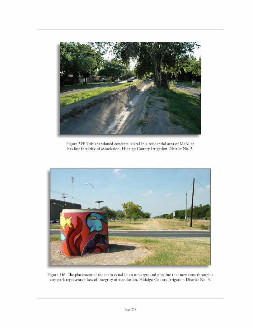
This abandoned concrete lateral in a residential area of McAllen Figure 315: has lost integrity of association, Hidalgo County Irrigation District No . 3 .
The placement of the main canal in an underground pipeline that now runs through a Figure 316: city park represents a loss of integrity of association, Hidalgo County Irrigation District No . 3 .
Page 258

The rural setting contributes to the integrity of association of this Figure 317: canal, Cameron County Irrigation District No . 6 .
The irrigation system retains its connection with the agricultural fields Figure 318: it serves and thus retains its integrity of association, Hidalgo County Irrigation District No . 2 .
Page 259

This second lift pumping plant lacks integrity of association Figure 319: because it is of modern design, it delivers water for municipal purposes and it lacks an agricultural setting, Hidalgo County Irrigation District No . 3 .
Page 260
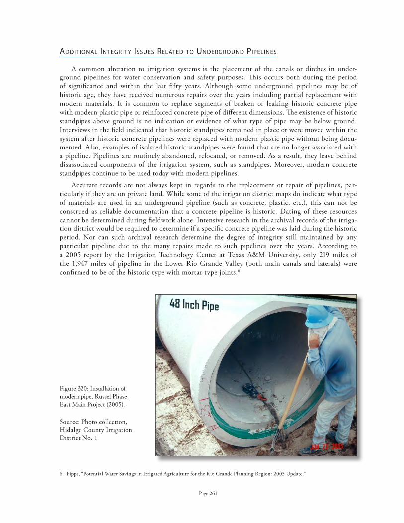
Installation of Figure 320: modern pipe, Russel Phase, East Main Project (2005) .
Source: Photo collection, Hidalgo County Irrigation District No . 1
Page 261
AdditionAl integrit y issues relAted to underground pipelines
A common alteration to irrigation systems is the placement of the canals or ditches in under-ground pipelines for water conservation and safety purposes . This occurs both during the period of significance and within the last fifty years . Although some underground pipelines may be of historic age, they have received numerous repairs over the years including partial replacement with modern materials . It is common to replace segments of broken or leaking historic concrete pipe with modern plastic pipe or reinforced concrete pipe of different dimensions . The existence of historic standpipes above ground is no indication or evidence of what type of pipe may be below ground . Interviews in the field indicated that historic standpipes remained in place or were moved within the system after historic concrete pipelines were replaced with modern plastic pipe without being docu-mented . Also, examples of isolated historic standpipes were found that are no longer associated with a pipeline . Pipelines are routinely abandoned, relocated, or removed . As a result, they leave behind disassociated components of the irrigation system, such as standpipes . Moreover, modern concrete standpipes continue to be used today with modern pipelines .
Accurate records are not always kept in regards to the replacement or repair of pipelines, par-ticularly if they are on private land . While some of the irrigation district maps do indicate what type of materials are used in an underground pipeline (such as concrete, plastic, etc .), this can not be construed as reliable documentation that a concrete pipeline is historic . Dating of these resources cannot be determined during fieldwork alone . Intensive research in the archival records of the irriga-tion district would be required to determine if a specific concrete pipeline was laid during the historic period . Nor can such archival research determine the degree of integrity still maintained by any particular pipeline due to the many repairs made to such pipelines over the years . According to a 2005 report by the Irrigation Technology Center at Texas A&M University, only 219 miles of the 1,947 miles of pipeline in the Lower Rio Grande Valley (both main canals and laterals) were confirmed to be of the historic type with mortar-type joints .6
6 . Fipps, “Potential Water Savings in Irrigated Agriculture for the Rio Grande Planning Region: 2005 Update .”

Construction of concrete forms for standpipe, East Main Project (2005) . Figure 321: Photo collection, Hidalgo County Irrigation District No . 1
Installation of 48" concrete pipe with rubber gasketed joints, East Main Project (2005) . Figure 322: Photo collection, Hidalgo County Irrigation District No . 1
Page 262

Initial construction on the placement of Curry Main Canal into underground pipeline (2004) . Figure 323: Photo collection, Hidalgo County Irrigation District No . 1
Page 263
With regards to contemporary replacements, although these underground pipelines may be along the same general alignment or easement, the underground placement represents a loss of integrity of location . It is necessary to continue to supply water through the existing canal scheduled for replacement while construction on the pipeline is underway, thus underground pipelines are often located adjacent to the historic canal rather than being placed within the actual canal itself . It is not uncommon for an entirely new alignment to be utilized, particularly if a new roadway or subdivision is planned in the area . In such cases, the new pipeline also represents a loss of integrity of design in the irrigation system . Moreover, the burying of what was once a raised, open canal surrounded with rich vegetation destroys the integrity of setting, feeling, materials, workmanship and, in some cases, design . With a lack of location, setting, feeling, materials, and workmanship, contemporary pipelines lack the necessary integrity for consideration as a character-defining feature of a historic irrigation system and thus should be considered as a contemporary intrusion .

Debris from numerous pipeline replacements is scattered throughout Figure 324: a land fill at Pinkston Road, Santa Cruz Irrigation District No . 15 .
Page 264
In recent years, it is becoming more commonplace to replace the canals with underground pipelines for water conservation reasons . These projects are well-documented in the recent records of the districts as they represent an enormous investment of funds . While the overall function of an irrigation system is not typically affected by the installation of pipelines, the determination of integ-rity for an irrigation district experiencing such modernization should consider the following factors:
Can it be demonstrated that the underground pipelines, are, in fact, of modern materials?1)
Are the pipelines part of the main conveyance system, or merely part of the final 2) delivery system constructed on private land?
If main canals and laterals have been replaced with underground pipelines, what 3) proportion do these represent in the overall length of the irrigation system?
The replacement of a preponderance of an irrigation system’s main canals and laterals with non-historic underground pipelines adversely affects the overall integrity of location, design, materials, workmanship, feeling and setting . Even though the original canals may still be in ex-istence, they no longer convey their historic significance in regards to the overall function of the system and may retain only their integrity of feeling and association which is insufficient for NRHP eligibility . Generally, if more than 50% of an irrigation system’s main canals and laterals are replaced with modern, underground pipelines, the overall system will not be NRHP eligible due to a lack of historic integrity .
The Texas Historical Commission and the Texas Department of Transportation have utilized this method of NRHP determination for irrigation resources since July of 2004 . After a thorough review of this issue that incorporates new data regarding the existence of historic pipelines, there appears to be no basis for altering the current policy . If an irrigation system contains a majority of its conveyance system in modern underground pipelines, it should be considered ineligible for listing in the National Register of Historic Places due to a lack of insufficient historic integrity of location, design, materials, workmanship, feeling, setting, and association .

Page 265
APPLICATIon oF THE nATIonAL REGISTER oF HISToRIC PLACES CRITERIA FoR THE EVALUATIon oF IRRIGATIon SYSTEmS
A property must be significant for consideration for eligibility for listing in the National Register of Historic Places . The historic context provided within this report provides the necessary patterns and trends in history associated with the irrigation systems of the region in order to understand their significance .
period of significAnce
The period of significance for Criterion A in the area of agriculture begins in 1904 with the arrival of the railroad ~ the St . Louis, Brownsville & Mexico Railway . The shipping of ag-ricultural produce, which is perishable, is wholly dependent upon a reliable and fast transpor-tation system . Before this date, the Lower Rio Grande Valley lacked a transportation network . A few pioneers of irrigation installed primitive systems before this date . But these early attempts at irrigation constituted localized experiments and were of a very different character from the large entrepreneurial investments that characterize the first decade of commercial agriculture in the Lower Rio Grande Valley .
The period of significance for Criterion A in the area of government/politics begins in 1914, the year the first irrigation district was organized under legislation passed by the State . The period of significance for any individual district would be the date of its establishment . Although an earlier law was passed in 1905, this law was so ineffective that no districts were able to organize . Although the 1905 law allowed for the organization of districts to build irrigation systems, they could not in-cur debt over one-quarter of the assessed property valuation . Thus, they could not purchase existing irrigation systems . The construction of an irrigation system would cost far more than the one-quarter of the assessed existing property valuation, as the property would have no real value until after it was under irrigation . A constitutional amendment, authored by Lon Hill of Harlingen and passed in 1913, allowed a district to both purchase and improve existing systems . Hill was an attorney who came to the Valley c .1900 from Beeville . His irrigation company became Cameron County Irrigation District No . 1 (Harlingen), the first irrigation district organized under the legislation .
The period of significance for Criteria B and C will be dependent upon the particular circum-stances of the irrigation system . For Criterion C, it will be the initial construction date of that particular irrigation system . For Criterion B, it will be the dates for which a person is associated with an irrigation resource in the Lower Rio Grande Valley .
The period of significance for Criteria A, B, and C terminates in 1953, the year in which Falcon Dam begins releasing water to the irrigation districts of the Lower Rio Grande Valley . This also incorporates the date in which the last private irrigation company, United Irrigation Company, ceased to function and became incorporated into a publicly owned and operated irrigation district (1952) . The Valley experienced a series of natural events from the late 1940s through the 1950s that devastated agricultural production . A severe drought, compounded by a series of freezes and hurricanes, destroyed millions of citrus trees as well as nursery stock . The agricultural economy of the Valley would not recover entirely until the early 1970s . But more importantly, the construction of Falcon Dam and the regulation of the waters of the Rio Grande River by federal and state agencies represented a dramatic turning point in the agricultural development of the Valley . The unlimited development of the Valley experienced in earlier decades was now restrained by the availability of water and regulation by the State of Texas .

Page 266
Criterion A
Irrigation systems can be eligible for the National Register under Criterion A in the area of agricul-ture or politics/government . Such resources will be most commonly eligible in the area of agriculture for their contributions to the development of commercial agriculture in the Lower Rio Grande Valley, particularly citrus, during a period of significance from 1904 to 1953 .
These resources should be considered potentially eligible at the local level of significance . Although the agricultural development of the Lower Rio Grande Valley had an economic impact on the State of Texas as a whole, the historic context does not address either the Valley’s agricultural develop-ment or the development of irrigation on a statewide basis to support consideration at a state level of significance .
The area of politics/government can also be utilized in developing the significance of an irrigation resource in the Lower Rio Grande Valley . The development of state laws pertaining to the establish-ment of irrigation districts was directly associated with the irrigation resources of the region . In order to be eligible under this area of significance, the resource should have a direct association with the development of legislation ~ for example, Cameron County Irrigation District No . 2 (San Benito), whose general manager played an important role in developing state legislation . These resources should be considered at the state level of significance .
As private entrepreneurs sometimes simultaneously developed both irrigation companies and towns, consideration could be given to Criterion A in the area of community planning and develop-ment . But the history of these companies is complex and involves, in many cases, subsidiaries that actually developed the towns . Moreover, there are not necessarily resources with an adequate level of integrity to link the irrigation system with the development of towns . Not all irrigation systems were necessarily associated with a particular town, even though they are all known today by a “common name,” such as Donna, Edinburg, etc . Due to the potential pitfalls and complexities, it is best to avoid this particular area of significance .
Irrigation resources considered eligible under Criterion A must retain a sufficient level of historic integrity to express the property’s connection with the historic context . While integrity of workman-ship and materials might not be as important, the overall design and location of the irrigation struc-ture remain integral to understanding the original intent of the system . The essential features of the design of an irrigation system, including its overall character defining features most of its original alignment during the period of significance, must be intact . Some evidence of its workmanship and historic materials must be present in order to convey a sense of materials, workmanship and feeling . As the function of an irrigation system relates directly to its agricultural context, it is important that it retain integrity of setting, feeling and association .

Page 267
Criterion B
Irrigation systems can be eligible for the National Register under Criterion B for their associa-tion with the lives of significant persons in the areas of engineering, agriculture, community plan-ning and development, and politics/government . The person must be individually significant within the historic context and not just “a member of an identifiable profession, class or social or ethnic group .”5 A farmer or the farmers in general who immigrated to the area would not be an appropriate person or group to include within this context . The irrigation resource must be directly associated with the significant events in the person’s productive life and ref lect the time period in which he or she achieved significance . It must retain its historic integrity from this particular time period, and not a later period of inf luence . It must also, of course, be the property most closely associated with that person’s activities .
Irrigation resources considered eligible under Criterion B must retain a sufficient level of historic integrity to express the property’s connection with the individual identified in the historic con-text . The irrigation system should retain a sufficient level of integrity of design, workmanship, and materials to represent the resource from the period in which the individual was associated with it . For example, an irrigation system associated with an important person from the 1920s and 1930s should not have a preponderance of irrigation features from the post-World War II era . The essential features of the design of an irrigation system, including its overall character defining features and its original alignment during the period of significance, must be intact . Integrity of setting, feeling and association should be sufficiently strong from the period of significance to connect the individual with the resource . According to the National Register Bulletin, “a basic integrity test for a property associated with an important event or person is whether a historical contemporary would recognize the property as it exists today .”6
Criterion C
Irrigation systems can be eligible for the National Register under Criterion C in the area of engineering for “the practical application of scientific principles to design, construct, and operate equipment, machinery, and structures to serve human needs .”7 To be eligible, the resource must “embody enough of the distinctive characteristics to be considered a true representative of the type, period or method of construction .”8 With respect to irrigation systems, the resource must retain a high degree of integrity for all of its the character defining features that are typical of such systems in the Lower Rio Grande Valley, including a historic age pumping plant at the river, subsequent lift plants, and a main canal with laterals in their original alignment . But in addition to this, a resource must be representative of its type, period and method of construction . The Bulletin clearly states that “a structure is eligible as a specimen of its type or period if it is an important example within its context .” 9 Comparative information is critical in establishing this context and understanding exactly how a particular irrigation structure is an important example of its type, period and method of construction . The period of significance will vary for any irrigation structure potentially eligible under Criterion C, dependent upon the specific dates of construction for the individual irrigation system . Not all irrigation systems of the Lower Rio Grande Valley will be potentially eligible for NRHP listing under Criterion C .
5 . National Register Bulletin: How To Apply the National Register Criteria for Evaluation, 48 .6 . Ibid .7 . National Register Bulletin: How To Complete the National Register Registration Form, 40 .8 . National Register Bulletin, How To Apply the National Register Criteria for Evaluation, 18 .9 . Ibid .

Page 268
Irrigation resources must have a demonstrated significance within their property type and retain the essential physical features that enable it to convey its historic significance . For example, Cameron County Irrigation District No . 2 (San Benito) was the only gravity flow irrigation system in the region that operated without a pumping plant, drawing water directly from the Rio Grande River . This was a significant advancement in the engineering of such structures . Today, however, the district oper-ates with a large modern pumping plant at the river due to changes in the course of the river from flooding . As the system no longer retains its integrity to express the original engineering innovation, it is not eligible for consideration for listing under Criterion C in the area of engineering .
For an irrigation system to be considered potentially eligible under Criterion C, the resource must retain a high degree of historic integrity of location, design, materials, and workmanship . It can be eligible if it has lost some of its historic materials in a small percentage of its lateral canals, but it must retain a sufficient level of these materials in a preponderance of its canals to convey a sense of its original construction . Setting is important in communicating the historical usage of the property as well . Moreover, where there is a total loss of setting, there is typically found a lack of integrity of materials, workmanship, association, and feeling due to the abandonment of canals in urban settings and the resulting placement of canals in underground pipelines .
boundAries for irrigAtion systems
Irrigation districts today have discrete boundaries that describe the lands that a particular irrigation district provides with water . The organization of these irrigation districts, enabled by state legislation, allowed small, local landowners to assume the cooperative operation of formerly private irrigation companies . The purchase of these private companies, as well as subsequent improvements, was financed through bonds funded by tax assessments on agricultural lands served by the irrigation district . This financing and management mechanism was pioneered by Utah in 1865 and subsequently by California in 1887 .10 The first such legislation in Texas was passed in 1905, but not utilized in the Lower Rio Grande Valley until a constitutional amendment passed in 1913 .
The irrigation districts, however, only own the right-of-way for their irrigation systems and the property for their lift stations and associated buildings such as district offices . Boundaries for irriga-tion resources evaluated as structures should begin at the point where water is diverted into the system and terminate at the endpoint of the system . The boundaries should include the right-of-way for the canal system and the property for the lift stations, not the entire acreage included within the modern boundaries served by an irrigation district . The delivery structures of an irrigation system generally extend upon the farmlands that they service . Although they extend onto privately owned lands not owned by the irrigation district and are maintained by the individual farmers, the irrigation districts may retain legal easements across the lands for such features . The boundaries of an irrigation system that included the delivery features across private land would be these easements associated with the features . While setting contributes to a property’s integrity, it should not include the agricultural fields within the boundaries of an irrigation structure .
If more than one irrigation system were physically linked and considered together, the multiple irrigation structures would constitute a historic district . It is not uncommon for irrigation districts to absorb other districts that have become inactive . In these particular cases, it is possible to have a historic district composed of two separate irrigation structures .
10 . NRHP nomination draft, “Irrigation and Water Supply Ditches and Canals in Colorado,” Section E, 30 .

Page 269
All or part of the acreage included within the boundaries served by an irrigation district would be included only if a “rural historic district” was under consideration for a particular area . As defined by the National Park Service, a rural historic landscape is “a geographical area that historically has been used by people, or shaped or modified by human activity, occupancy, or intervention, and that possesses a significant concentration, linkage, or continuity of areas of land use, vegetation, buildings and structures, roads and waterways, and natural features .” 1 1 Such a “rural historic district” would encompass not only the components of the irrigation system, but also the adjacent farmlands and their associated buildings, structures and sites . In any proposed rural historic district, an irrigation system should be assessed as a contributing or noncontributing component of the district .
For individual buildings, such as historic-age pumping plants no longer part of an irrigation system, the boundaries should be selected to include the building itself and any ancillary buildings (such as machine shops, warehouses or sheds) . The boundaries should not, however, include the entire irrigation system if the building is being considered for NRHP eligibility on an individual basis alone . This is particularly important when this building type is no longer connected to the irrigation system by a functioning canal system .
11 . National Register Bulletin, Guidelines for Evaluating and Documenting Rural Historic Landscapes, 1 .

Appendix

Date Established name of District Common name
of District District Status
Page 271
1914 Cameron Co . No . 1 Harlingen Active, absorbs Cameron 15
1916 Cameron Co . No . 2 San Benito Active, absorbs Cameron 13 and 18 (partial)
1917 La Feria/Cameron [No .3] La Feria Active
1918 Cameron Co . No . 4 Santa Maria Active
1919 Cameron Co . No . 5 Brownsville Active
1922 Cameron Co . No . 6 Los Fresnos Active, absorbs Cameron 12
1927 Cameron Co . No . 7 West Brownsville Dissolved 1970s
1927 Cameron Co . No . 8 Barreda Plantation Dissolved 1950
– Cameron Co . No . 9 See Hidalgo and Cameron Co . No . 9
1928 Cameron Co . No . 10 Rutherford-Harding Active
1928 Cameron Co . No . 11 Bayview Active
1928 Cameron Co . No . 12 Kempner Tract Incorporated intoCameron 6
1928 Cameron Co . No . 13 Arroyo Gardens Incorporated into Cameron 2
1929 Cameron Co . No . 14 Offices in Olmito Status unknown, no records found
1929 Cameron Co . No . 15 McLeod-Hood Tract Incorporated into Cameron 1
1930 Cameron Co . No . 16 Rice Tract Active
1930 Cameron Co . No . 17 Sams-Porter Tract Status unknown, no records found
1930 Cameron Co . No . 18 Monte Grande Incorporated into Cameron 2 (partially)
comprehensive list of irrigAtion districts estAblished in the lower rio grAnde vAlley

Date Established name of District Common name
of District District Status
Page 272
1931 Cameron Co . No . 19 Adams Gardens Active
1951 Cameron Co . No . 20 Rio Grande Palms/ Russell Never fully functioning
1953 Cameron Co . No . 21 Status unknown, not historic
1914 Donna/Hidalgo Co . No . 1 Donna Active
1926 Hidalgo Co . No . 1 Edinburg Active, absorbs Hidalgo 11
1920 Hidalgo Co . No . 2 San Juan Active
1921 Hidalgo Co . No . 3 McAllen 3 Active
1922 Hidalgo Co . No . 4 Becomes Hidalgo No . 1 in 1926, name change only
1925 Hidalgo Co . No . 5 Progreso Active
1927 Hidalgo Co . WCID No . 6 Goodwin Tract Active
1929 Hidalgo Co . WID No . 6 Engelman Gardens Active
1927 Hidalgo Co . No . 7 North Mission Incorporated into United
1929 Hidalgo Co . No . 8 Status unknown, no records found
1927 Hidalgo & Cameron Co . No . 9 Mercedes Active
1930 Hidalgo Co . No . 10 Status unknown, no records found
1923 Hidalgo Co . No . 11 Bentsen Incorporated into Hidalgo 1
1929 Hidalgo Co . No . 12 Dissolved 1945
1936 Hidalgo Co . No . 13 Baptist Seminary Active
1931 Hidalgo Co . No . 14 Incorporated into Hidalgo 7/United
Districts, contd.

Page 273
1942 Hidalgo Co . No . 15 Santa Cruz Active
1946 Hidalgo Co . No . 16 Mission 16 Active
1947 Hidalgo Co . No . 17 Converted to MUD
1951 Hidalgo Co . No . 18 Monte Grande Active
1952 Hidalgo Co . No . 19 Sharyland Active
1951 Hidalgo – Valley Acres Valley Acres Active
1916 United Irrigation District United Privately owned, becomes public
irrigation district in 1952
1952 United Irrigation District United Active, absorbs Hidalgo 7 & 14
1914 United Irrigation District
See Willacy Co . No . 1 . Dissolved 1918, after tax payer revolt, re-organized later date .
1929 Willacy Co . No . 1 Delta Lake Active
Date Established name of District Common name
of District District Status
Districts, contd.

Page 274
BiBlioGrapHy
The History of Agriculture and Irrigation in the West
Ackerly, Neal . Historic and Modern Irrigation Systems in El Paso, Texas. 2 volumes . Las Cruces, New Mexico: Center for Anthropological Research, 1994 .
Bogener, Stephen . Ditches Across the Desert: Irrigation in the Lower Pecos Valley. Lubbock: Texas Tech University Press, 2003 .
Clark, Ira . Water in New Mexico: A History of Its Management and Use. Albuquerque: University of New Mexico Press, 1987 .
Conrad, Glenn and Ray Lucas . White Gold: A Brief History of the Louisiana Sugar Industry, 1795-1995. Lafayette: University of Southwestern Louisiana, 1995 .
Cox, I . Waynne . The Spanish Acequias of San Antonio . San Antonio: Maverick Publishing Company, 2005 .
Glick, Thomas F . Irrigation and Hydraulic Technology: Medieval Spain and Its Legacy . Brookfield, Vermont: Ashgate Publishing Company, 1996 .
Glick, Thomas F . Irrigation and Society in Medieval Valencia. Cambridge: Belknap Press, 1970 .
Glick, Thomas F . The Old World Background of the Irrigation System of San Antonio, Texas. El Paso: Texas Western Press, 1972 .
Hufstetler, Mark and Lon Johnson . Watering the Land: The Turbulent History of the Carlsbad Irrigation District. Denver: National Park Service, Rocky Mountain Region, and the Bureau of Reclamation, 1993 .
Hurt, R . Douglas . American Agriculture: A Brief History. Ames: Iowa State University Press, 1994 .
Hurt, R . Douglas . Agricultural Technology in the Twentieth Century. Manhattan: Sunflower University Press, 1991 .
Meyer, Michael . Water in the Hispanic Southwest: A Social and Legal History, 1550-1850. Tucson: University of Arizona Press, 1996 .
Pisani, Donald . From the Family Farm to Agribusiness: The Irrigation Crusade in California and the West, 1850-1931. Berkeley: University of California Press, 1984 .
Pisani, Donald . To Reclaim a Divided West: Water, Law, and Public Policy, 1848-1902. Albuquerque: University of New Mexico Press, 1992 .
Reisner, Marc . Cadillac Desert: The American West and Its Disappearing Water. New York: Viking Penguin, Inc . 1986 .

Page 275
Smythe, William . The Conquest of Arid America. New York: Macmillan, 1905 .
White, Alice . “History of the Development of Irrigation in the El Paso Valley .” M .A . thesis, Department of History, University of Texas at El Paso, 1950 .
Worster, Donald . Rivers of Empire: Water, Aridity, and the Growth of the American West. New York: Pantheon Books, 1985 .
History of Irrigation Engineering and Technology
Clifton, A . R . C . Irrigation. Perth: F .W . Simpson, 1927 .
Davis, Arthur . Irrigation Engineering. New York: John Wiley & Sons, Inc ., 1919 .
Davis, Arthur . Irrigation Works Constructed by the United States Government. New York: J . Wiley, 1917 .
Etcheverry, B . A . Irrigation Practice and Engineering. Vol. II: Conveyance of Water. New York: McGraw-Hill Book Co ., 1915 and 1933 .
Fortier, Samuel . The Border Method of Irrigation. USDA Farmers’ Bulletin No . 1243, 1927 .
Fortier, Samuel . Practical Information for Beginners in Irrigation. USDA Farmers’ Bulletin No . 864, 1917 .
Glick, Thomas F . Irrigation and Hydraulic Technology: Medieval Spain and Its Legacy. Great Yarmouth, Norfolk: Galliard Printers, Ltd ., 1996 .
Houk, Ivan . Irrigation Engineering. New York: Wiley, 1951 .
Hutson, William Ferguson . Irrigation Systems in Texas. U.S. Geological Survey, Water Supply and Irrigation Papers No . 13, Washington D .C .: Government Printing Office, 1898 .
Irrigation Age (formerly: National Land and Irrigation Journal); various issues between 1910 and 1918 .
Israelsen, Orson . Irrigation Principles and Practices. New York: John Wiley and Sons, Inc ., 1932 .
Israelsen, Orson and Vaughn Hansen . Irrigation Principles and Practices . New York: John Wiley and Sons, Inc ., 1962 .
Kaser, Rolland . Irrigation and Drainage Studies of Texas Rivers. US Study Commission, 1961 .
King, Franklin . Irrigation and Drainage: Principles and Practice of Their Cultural Phases. New York: Macmillan, 1899 .
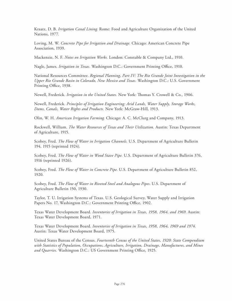
Page 276
Kraatz, D . B . Irrigation Canal Lining. Rome: Food and Agriculture Organization of the United Nations, 1977 .
Loving, M . W . Concrete Pipe for Irrigation and Drainage. Chicago: American Concrete Pipe Association, 1939 .
Mackenzie, N . F . Notes on Irrigation Works. London: Constable & Company Ltd ., 1910 .
Nagle, James . Irrigation in Texas. Washington D .C .: Government Printing Office, 1910 .
National Resources Committee . Regional Planning, Part IV: The Rio Grande Joint Investigation in the Upper Rio Grande Basin in Colorado, New Mexico and Texas. Washington D .C .: U .S . Government Printing Office, 1938 .
Newell, Frederick . Irrigation in the United States. New York: Thomas Y . Crowell & Co ., 1906 .
Newell, Frederick . Principles of Irrigation Engineering: Arid Lands, Water Supply, Storage Works, Dams, Canals, Water Rights and Products. New York: McGraw-Hill, 1913 .
Olin, W . H . American Irrigation Farming. Chicago: A . C . McClurg and Company, 1913 .
Rockwell, William . The Water Resources of Texas and Their Utilization. Austin: Texas Department of Agriculture, 1915 .
Scobey, Fred . The Flow of Water in Irrigation Channels. U .S . Department of Agriculture Bulletin 194, 1915 (reprinted 1924) .
Scobey, Fred . The Flow of Water in Wood Stave Pipe. U .S . Department of Agriculture Bulletin 376, 1916 (reprinted 1926) .
Scobey, Fred . The Flow of Water in Concrete Pipe. U .S . Department of Agriculture Bulletin 852, 1920 .
Scobey, Fred . The Flow of Water in Riveted Steel and Analogous Pipes . U .S . Department of Agriculture Bulletin 150, 1930 .
Taylor, T . U . Irrigation Systems of Texas . U .S . Geological Survey, Water Supply and Irrigation Papers No . 17, Washington D .C .: Government Printing Office, 1902 .
Texas Water Development Board . Inventories of Irrigation in Texas, 1958, 1964, and 1969. Austin: Texas Water Development Board, 1971 .
Texas Water Development Board . Inventories of Irrigation in Texas, 1958, 1964, 1969 and 1974. Austin: Texas Water Development Board, 1975 .
United States Bureau of the Census . Fourteenth Census of the United States, 1920: State Compendium with Statistics of Population, Occupations, Agriculture, Irrigation, Drainage, Manufactures, and Mines and Quarries. Washington D .C .: US Government Printing Office, 1925 .

Page 277
United States Bureau of the Census . Fifteenth Census of the United States, 1930: Irrigation of Agricultural Lands. Washington D .C .: US Government Printing Office, 1932 .
United States Bureau of the Census . Sixteenth Census of the United States, 1940: Irrigation of Agricultural Lands. Washington D .C .: US Government Printing Office, 1943 .
Wilcox, Lucius . Irrigation Farming. New York: Orange Judd Company, 1902 .
Zimmerman, Josef . Irrigation. New York: John Wiley and Sons, 1966 .
History of Irrigation in the Lower Rio Grande Valley
Ackerly, Neal . “Historic and Modern Irrigation Systems” in John Peterson and David Brown, eds . El Valle Bajo: The Culture and History of the Lower Rio Grande Valley of El Paso. Austin: Archaeological Research, Inc ., 1992 .
Allhands, James L . Gringo Builders. Privately printed, 1931 .
Allhands, James L . Looking Back over 98 Years: The Autobiography of James L.Allhands. Malibu: Pepperdine University, 1978 .
Amberson, Mary Margaret McAllen, James A . McAllen and Margaret H . McAllen . I Would Rather Sleep in Texas: A History of the Lower Rio Grande Valley and the People of the Santa Anita Land Grant. Austin: Texas State Historical Association, 2003 .
American Rio Grande Land and Irrigation Company: Irrigated Lands in Lower Rio Grande Valley. Brochure (192?), Center for the Study of American History, University of Texas at Austin .
Bowie, Augustus . Irrigation in Southern Texas. Washington D .C .: Government Printing Office, 1905 .
Carter, Rufus . “A Historical Study of Floods Prior to 1892 in the Rio Grande Watershed .” M .A . thesis, civil engineering, University of New Mexico, Albuquerque, 1952 .
Dalrymple, Tate . “The Water Situation in the Lower Rio Grande Valley,” Report Issued by the Water-master for the 93rd Judicial District Court, Edinburg in State of Texas, et . al . vs . Hidalgo County Water Control and Improvement District No . 18 et . al . (September 20, 1965) . On file in the Cramer Collection, Museum of South Texas History Archives, Edinburg, Texas .
Delta Orchards Co . Lands and Orchards in the Famous Lower Valley of the Rio Grande (brochure) . Raymondville: Delta Orchards, 1933 .
Dougherty, Edward . Availability of the Counties of Cameron and Hidalgo on the Lower Rio Grande, Texas, for Agricultural, Stock Raising and Manufacturing Purposes. Brownsville: Sentinel Book and Job Printing Office, 1869 .
Hill, Kate Adele . Lon C. Hill, 1862-1935: Lower Rio Grande Valley Pioneer. San Antonio: Naylor Company, 1973 .

Page 278
Hughes, William and Joe Motheral . Irrigated Agriculture in Texas. College Station: Texas Agricultural Experiment Station, 1950 .
Hutson, William Ferguson . Irrigation Systems in Texas. U .S . Geological Survey, Water Supply and Irrigation Papers No . 13, Washington D .C .: Government Printing Office, 1898 .
“Irrigation Was Started in Big Way in Willacy,” Brownsville Herald (Dec . 6, 1942) .
Kaser, Rolland . Irrigation and Drainage Studies of Texas Rivers. US Study Commission, 1961 .
Kincaid, Naomi . “Surface Water in Texas,” West Texas Historical Association Yearbook (Oct ., 1967) 44-64 .
McNail, J .L . “The History and Development of Irrigation in the Lower Rio Grande Valley .” M .A . thesis, Texas College of Arts and Industries, 1948 .
Matthews, William . “A History of Irrigation in the Lower Rio Grande Valley .” M .A . thesis, University of Texas, 1938 .
Missouri Pacific Lines . The Lower Rio Grande Valley of Texas. Chicago: Missouri Pacific Lines, 1931 .
Monty’s Monthly: Digest of Valley Activities (1919-1938) . Published by P .E . Montgomery in McAllen, Texas .
Nagle, James . Irrigation in Texas. Washington D .C .: Government Printing Office, 1910 .
Newell, Frederick . Irrigation in the United States. New York: Thomas Y . Crowell & Co ., 1906 .
Rister, M . Edward, et . al . “Economic Methodology for South Texas Irrigation Projects: RGIDECON .” unpublished paper . College Station: Texas A&M, Texas Water Resources Institute, October 2002 .
Robertson, Frank . “History of Irrigaiton in the Valley,” Mercedes News Tribune (Sept .17, 1937) .
Robertson, Frank . “Water District Story,” undated clipping, Irrigation Scrapbook, South Texas History Museum, Edinburg, Texas .
San Benito Land and Water Company . A Statement of Facts Concerning the Farming Lands and Gravity Irrigation Canal of the San Benito Land and Water Company… Houston: Cumming and Sons, 1910 .
Smith, Eldo, comp . Progreso Haciendas: Citrus Fruit and Farm Lands in the Lower Rio Grande Valley of Texas. Weslaco: Progreso Development Co ., 1930 .
South Coast Company . The San Jose Orchards, Lyford, Texas. Chicago: The South Coast Company, 1910 .
Southern Pacific Company, Agricultural Department . The Magic Valley of the Lower Rio Grande. Houston: Southern Pacific Lines, 1927 .
Southern Pacific Company, Agricultural Department . The Magic Valley of the Lower Rio Grande: The Land of Golden Fruit. Houston: Southern Pacific Lines, 1931 .

Page 279
Taylor, T . U . Irrigation Systems of Texas . U .S . Geological Survey, Water Supply and Irrigation Papers No . 17, Washington D .C .: Government Printing Office, 1902 .
Texas Board of Water Engineers . Seepage Losses from Canals in Texas. Austin: Texas Board of Water Engineers, 1946 .
Texas Water Development Board . Inventories of Irrigation in Texas, 1958, 1964, and 1969. Austin: Texas Water Development Board, 1971 .
Texas Water Development Board . Inventories of Irrigation in Texas, 1958, 1964, 1969 and 1974. Austin: Texas Water Development Board, 1975 .
The Tropical Farmer, Mission, Texas (1920-)
United States Reclamation Service . Report on Crops on the Rio Grande Project, Reclamation Record (1916 through 1922) . Washington D .C .: Government Printing Office .
Watson, Mrs . James . The Lower Rio Grande Valley of Texas, and Its Builders. Mission: The Lower Rio Grande Valley of Texas, and Its Builders, Inc, 1931 .
Willard, Rex . The Status of Farming in the Lower Rio Grande Irrigated District of Texas. Washington D .C .: Government Printing Office, 1916 .
[W . E . Stewart Land Co .] The Big Business of Farming: Down on the Rio Grande. Kansas City: W . E . Stewart Land Co ., 192? .

Page 280
Irrigation Districts and Water Law
Baade, Hand . “The Historical Background of Texas Water Law: A Tribute to Jack Pope .” St. Mary’s Law Journal. Vol . 18 (1986) 2-97 .
Gilchrist, Gwendolyn . “Texas Water Resources Management by Water Districts and River Authorities .” M .A . thesis, University of Texas at Austin, 1992 .
Huffman, Roy . Irrigation Development and Public Water Policy. New York: Ronald Press Company, 1953 .
Hutchins, Wells . Irrigation Districts: Their Organization, Operation and Financing. US Department of Agriculture, 1931 .
Stubbs, Megan, et .al . “Evolution of Irrigation Districts and Operating Institutions: Texas Lower Rio Grande Valley,” unpublished paper . College Station: Texas A&M, Texas Water Resources Institute, July 2003 .
Board of Water Engineers . First Report of the Board of Water Engineers for the State of Texas, September 1, 1913 through August 31, 1914. Austin, 1915 .
Board of Water Engineers . Second Report of the Board of Water Engineers for the State of Texas, September 1, 1914 through August 31, 1916. Austin, 1917 .
Board of Water Engineers . Third Report of the Board of Water Engineers for the State of Texas, September 1, 1916 through August 31, 1918. Austin, 1919 .
Board of Water Engineers . Fourth Report of the Board of Water Engineers for the State of Texas, September 1, 1918 through August 31, 1920. Austin, 1921 .
Board of Water Engineers . Fifth Report of the Board of Water Engineers for the State of Texas, September 1, 1920 through August 31, 1922. Austin, 1923 .
Board of Water Engineers . Sixth Report of the Board of Water Engineers for the State of Texas, September 1, 1922 through August 31, 1924. Austin, 1925 .
Board of Water Engineers . Seventh Report of the Board of Water Engineers for the State of Texas, September 1, 1924 through August 31, 1926. Austin, 1927 .
Board of Water Engineers . Eighth Report of the Board of Water Engineers for the State of Texas, September 1, 1926 through August 31, 1928. Austin, 1929 .
Board of Water Engineers . Ninth Report of the Board of Water Engineers for the State of Texas, September 1, 1928 through August 31, 1930. Austin, 1931 .
Board of Water Engineers . Tenth Report of the Board of Water Engineers for the State of Texas, September 1, 1930 through August 31, 1932. Austin, 1933 .
Board of Water Engineers . Eleventh Report of the Board of Water Engineers for the State of Texas, September 1, 1932 through August 31, 1934. Austin, 1935 .

Page 281
Board of Water Engineers . Twelfth Report of the Board of Water Engineers for the State of Texas, September 1, 1934 through August 31, 1936. Austin, 1937 .
Board of Water Engineers . Thirteenth Report of the Board of Water Engineers for the State of Texas, September 1, 1936 through August 31, 1938. Austin, 1939 .
Board of Water Engineers . Fourteenth Report of the Board of Water Engineers for the State of Texas, September 1, 1938 through August 31, 1940. Austin, 1941 .
Board of Water Engineers . Fifteenth Report of the Board of Water Engineers for the State of Texas, September 1, 1940 through August 31, 1942. Austin, 1943 .
Board of Water Engineers . Progress Report of the Texas Board of Water Engineers for the Period, September 1, 1942 through August 31, 1944. Austin, 1944 .
Board of Water Engineers . Seventeenth Progress Report of the Texas Board of Water Engineers for the Period, September 1, 1944 through August 31, 1946. Austin, 1946 .
Board of Water Engineers . Progress Report of the Texas Board of Water Engineers for the Period, September 1, 1946 through August 31, 1948. Austin, 1948 .
Board of Water Engineers . Nineteenth Report of the Texas Board of Water Engineers for the Period, September 1, 1948 through August 31, 1950. Austin, 1950 .
Board of Water Engineers . Twentieth Report of the Texas Board of Water Engineers for the Period, September 1, 1950 through August 31, 1952. Austin, 1952 .
Board of Water Engineers . Twenty-First Report of the Texas Board of Water Engineers for the Period, September 1, 1952 through August 31, 1954. Austin, 1954 .
Board of Water Engineers . Twenty-Second Report of the Texas Board of Water Engineers for the Period, September 1, 1954 through August 31, 1956. Austin, 1956 .
Thrombley, Woodworth . Special Districts and Authorities in Texas. Austin: The University of Texas, Institute of Public Affairs, 1959 .

Page 282
General History of the Lower Rio Grande Valley
Allhands, James L . Gringo Builders. Privately printed, 1931 .
Alonzo, A . A . Tejano Legacy: Rancheros and Settlers in South Texas, 1734-1900. Albuquerque: University of New Mexico Press, 1998 .
Amberson, Mary Margaret McAllen, James A . McAllen and Margaret H . McAllen . I Would Rather Sleep in Texas: A History of the Lower Rio Grande Valley and the People of the Santa Anita Land Grant. Austin: Texas State Historical Association, 2003 .
Arreola, Daniel . Tejano South Texas: A Mexican American Cultural Province. Austin: University of Texas Press, 2002 .
Barton, Florence Ward . Roots by the River: A Story of Texas Tropical Borderland. Canyon, Texas: Staked Plains Press, 1978 .
Bogener, Steve . Ditches Across the Desert: Irrigation in the Lower Pecos Valley. Lubbock: Texas Tech University Press, 2003 .
Dillman, Daniel . “Transformation of the Lower Rio Grande of Texas and Tampaulipas .” Ecumene. Vol . 2, no . 2 (1970) 3-11 .
Dobbs, Ricky . Yellow Dogs and Republicans: Allan Shivers and Texas Two-Party Politics. College Station: Texas A&M University Press, 2005 .
Foster, Lynn . A Brief History of Mexico. New York: Facts on File, Inc ., 1997 .
Garza, Alicia and Christopher Long . “Cameron County,” in the New Handbook of Texas. Austin: Texas State Historical Association, 1996 .
Garza, Alicia . “Willacy County,” in the New Handbook of Texas. Austin: Texas State Historical Association, 1996 .
Gerhardt, Karen and Blanca Tamez . Weslaco. Charleston: Arcadia Publishing, 1999 .
Gerhardt, Karen and Laura Lincoln . Donna, Texas. Chicago: Arcadia Publishing, 2002 .
Hall, Linda . Oil, Banks, and Politics: The United States and Postrevolutionary Mexico, 1917-1924. Austin: University of Texas Press, 1995 .
Harding, Glenn and Cindy Lee . Rails to the Rio. Austin: Morgan Printing, 2003 .
Heller, Dick . “History of Mission, Texas .” Unpublished manuscript .
Hidalgo County Centennial Corporation . Hidalgo County Centennial, 1852-1952. Mission: Times Publishing Company, 1952 .
Kazin, Michael . A Godly Hero: The Life of William Jennings Bryan. New York: Knopf, 2006 .
Kearney, Milo and Anthony Knopp . Boom and Bust: The Historical Cycles of Matamoros and Brownsville. Austin: Eakin Press, 1991 .

Page 283
Kibler, Karl and Martha Doty Freeman . “Preliminary Cultural Resources Investigations for the Pharr-Reynosa International Bridge, Hidalgo County, Texas .” Report of Investigations, No . 90 . Austin: Prewitt and Associates, Inc ., 1993 .
Krug, James . “Benjamin Franklin Yoakum and the St . Louis, Brownsville, and Mexico Railroad .” M . A . thesis, Texas A&M University, Kingsville, 1999 .
The Lower Rio Grande Valley Without a Rival. Brownsville: Lower Rio Grande Valley Commercial Club, 1910 .
Miller, Char, editor . Fluid Arguments. Tucson: The University of Arizona Press, 2001 .
Montejano, David . Anglos and Mexicans in Making of Texas, 1836-1986. Austin: University of Texas, 1987 .
Pierce, Frank . A Brief History of the Lower Rio Grande Valley. Menasha, Wisconsin: George Banta Publishing, 1917 .
Ramsdell, Charles . The Book of Texas. Garden City: Doubleday, Page and Company, 1928 .
“Red Grapefruit Called Million Dollar Mistake,” Lower Rio Grande Valley Yearbook . Mission: Lower Rio Grande Valley Chamber of Commerce, 1968 .
Sánchez, Mario, editor . A Shared Experience: The History, Architecture and Historic Designations of the Lower Rio Grande Heritage Corridor. Austin: Texas Historical Commission, 1994 .
Sonnichsen, C . L . Pass of the North: Four Centuries on the Rio Grande, Volume II: 1918-1980. El Paso: Texas Western Press, 1968 .
Spence, Ruth Griffin . Nickel Plated Highway to Hell. Privately printed, no date .
Stambaugh, J . Lee and Lillian Stambaugh . The Lower Rio Grande Valley of Texas. San Antonio: The Naylor Company, 1954 .
Valley By-Liners . Gift of the Rio: A Story of Texas Tropical Borderland. Canyon, Texas: Staked Plains Press, 1975 (vol . 1) .
Valley By-Liners . Rio Grande Round-Up: A Story of Texas Tropical Borderland. Burnet: Eakin Publications, 1980 (vol . 3) .
Valley By-Liners . Roots by the River: A Story of Texas Tropical Borderland. Canyon, Texas: Staked Plains Press, 1978 (vol . 2) .
Yearbook of the Lower Rio Grande Valley and Northern Mexico (1950, 1960, 1961, 1962) .
Yoakum, B . F . Transportation Facilities: The Foundation of Industrial and Agricultural Prosperity. Austin: Austin Printing Company, 1908 .

Page 284
National Register Nominations, Historic Contexts and Official Texas Historical Marker Files
Ackerly, Neal and Frank Wozniak . “A Review of the Historic Significance of and Management Recommendations for Preserving New Mexico’s Acequia Systems,” Prepared by Dos Rios Consultants Inc . for the Historic Preservation Division of the State of New Mexico, 1996 .
“Carlsbad Irrigation District, Eddy County, New Mexico .” National Historic Landmark (1964) National Register files, New Mexico State Historic Preservation Office, Santa Fe, New Mexico .
Miller, C . W . “El Paso County Water Improvement District No . 1 .” National Register Nomination (1997) . National Register files, Texas Historical Commission, Austin, Texas .
Miller, C . W . “Franklin Canal .” National Register Nomination (1991) . National Register files, Texas Historical Commission, Austin, Texas .
“Mission Canal Company Second Lift Pumphouse .” National Register Nomination (2002) . National Register files, Texas Historical Commission, Austin, Texas .
Myers, Terri and Karen Weitze . “Louisiana-Rio Grande Canal Company Irrigation System .” National Register Nomination (1995) . National Register files, Texas Historical Commission, Austin, Texas .
“Old Brulay Plantation, near Brownsville, Cameron County, Texas .” National Register Nomination (1975) . National Register files, Texas Historical Commission, Austin, Texas .
“Percha Diversion Dam .” National Register Nomination (1979) . National Register files, New Mexico State Historic Preservation Office, Santa Fe, New Mexico .
Phillips, David . “Elephant Butte Irrigation District .” National Register Nomination (1997) . National Register files, New Mexico State Historic Preservation Office, Santa Fe, New Mexico .
Weitze, Karen . “Louisiana-Rio Grande Canal Company Irrigation System .” National Historic Landmark Nomination, 1992 . National Register files, Texas Historical Commission, Austin, Texas .
Wozniak, Frank . “Irrigation in the Rio Grande Valley, New Mexico: A Study and Annotated Bibliography of the Development of Irrigation Systems .” Fort Collins, Colorado: USDA Forest Service, Rocky Mountain Research Station, 1998 .
Wozniak, Frank . “Irrigation in the Rio Grande Valley, New Mexico: A Study of the Development of Irrigation Systems Before 1945” . Santa Fe: New Mexico Historic Preservation Division, 1987 .

This lovely young lady, a participant in one of the many annual fall festivals in the Valley, wears a gown made from grapefruit peel and sliced beets, carrots and turnips .
Source: National Geographic, January, 1939
Page 285
Historic Contexts
Holleran, Michael . “Statewide Historic Context Study: Irrigation Ditches and Canals (Colorado) .” Colorado Historical Society, 2005 .
JRP Historical Consulting Services . “Water Conveyance Systems in California: Historic Context Development and Evaluation Procedures .” California Department of Transportation, 2000 .
Marker Applications
Goza, Goldsby . “American Rio Grande Land and Irrigation Company, Mercedes, Hidalgo County, Texas .” (1978) Official Texas Historical Marker files, Texas Historical Commission, Austin, Texas .
Norton, Robert and Spurgeon Brown “Hidalgo Irrigation Pumps, Hidalgo, Hidalgo County, Texas .” (1988) Official Texas Historical Marker files, Texas Historical Commission, Austin, Texas .
Archival Sources
State Board of Water Engineers files, Texas State Library and Archives, Austin, Texas
Map Collection . University of Texas - Pan American, Edinburg, Texas .
John Shary Collection . Rio Grande Historical Society Collection . Pan American University, Edinburg, Texas .
South Texas History Museum Archives, Edinburg, Texas (multiple collections, including irrigation scrapbooks) .