a fem-experimental approach for the development of a...
TRANSCRIPT

Research ArticleA FEM-Experimental Approach for the Development of aConceptual Linear Actuator Based on Tendril’s Free Coiling
Luca Cortese,1,2 Selena Milanovic,1 and Renato Vidoni1
1Faculty of Science and Technology, Free University of Bozen-Bolzano, Piazza Università 5, 39100 Bolzano, Italy2Department of Mechanical and Aerospace Engineering, Sapienza University of Rome, Via Eudossiana 18, 00184, Rome, Italy
Correspondence should be addressed to Renato Vidoni; [email protected]
Received 10 March 2017; Revised 15 May 2017; Accepted 30 May 2017; Published 25 July 2017
Academic Editor: Estefanía Peña
Copyright © 2017 Luca Cortese et al. This is an open access article distributed under the Creative Commons AttributionLicense, which permits unrestricted use, distribution, and reproduction in any medium, provided the original work isproperly cited.
Within the vastness of the plant species, certain living systems show tendril structures whose motion is of particularinterest for biomimetic engineers. Tendrils sense and coil around suitable grips, and by shortening in length, they erectthe remaining plant body. To achieve contraction, tendrils rotate along their main axis and shift from a linear to adouble-spring geometry. This phenomenon is denoted as the free-coiling phase. In this work, with the aim ofunderstanding the fundamentals of the mechanics behind the free coiling, a reverse-engineering approach based on thefinite element method was firstly applied. The model consisted of an elongated cylinder with suitable materialproperties, boundary, and loading conditions, in order to reproduce the kinematics of the tendril. The simulationsucceeded in mimicking coiling faithfully and was therefore used to validate a tentative linear actuator model based onthe plant’s working principle. More in detail, exploiting shape memory alloy materials to obtain large reversibledeformations, the main tendril features were implemented into a nickel-titanium spring-based testing model. Theresults of the experimental tests confirmed the feasibility of the idea in terms of both functioning principles and actualperformance. It can be concluded that the final set-up can be used as a base for a prototype design of a new kind ofa linear actuator.
1. Introduction
Climbing plants can be a meaningful source of inspirationfor biomimetic purposes for their intriguing complexityand functional perspectives [1]. Among these, climbingtendril-bearer plants show an interesting way to search,grasp, and climb a support [2–4], a behavior that can bestudied and implemented in future bio-inspired technolo-gies [5–8]. Indeed, by means of tendrils, that is, filiform,irritable, and long organs, they are able to coil around asupport and grasp it, allowing the plant to gain verticaldisplacement. As it is known, tendrils describe three mainmovements [3, 9–16]:
(i) Circumnutation: an endogenous movement thatincreases the probability of contact with supports
(ii) Contact coiling: during which the stimulated tendrilcoils around a support
(iii) Free coiling: throughout which the tendril developshelical coils along its axis, not necessarily as a resultof stimulation.
As a whole, the study has been divided into two sections:the first presents a model and FEA of the tendril’s free-coilingphase and the second investigates the efficiency of thetendril’s geometry in lifting weights. Hence, the core lies inanalyzing the effects of its geometry on its range ofmotion, rather than in justifying its internal structure.Indeed, starting from a linear configuration, the tendril’sgeometry evolves into two helices with opposite rotationaldirections. The rotation around its axial axis is denoted as
HindawiApplied Bionics and BiomechanicsVolume 2017, Article ID 6450949, 12 pageshttps://doi.org/10.1155/2017/6450949

free coiling and begins after the tendril has completed thephase of contact coiling. This final change in geometryresults in a contraction, therefore lifting the remainingplant body. The fundamentals for this behavioral analysishave been extracted from results available in literature(e.g., [8, 17]).
Moreover, this pulling movement is achieved by creatingan elastic spring-like connection between the stem and thegrasped support, able to resist to highly stressed conditionssuch as wind and loads [3].
Recent biological studies [17] have shown that the ten-dril body is partially made of a specific kind of cellsnamed G-cells (or G-fibers). These are typically found intrees and are those which dehydrate during the growthprocess granting stiffness to the plant’s body. Indeed, dur-ing the free-coiling process, the entire structure dehy-drates, including the G-fibers, and thus becomes morerigid, preventing uncoiling. In general, lignification seemsto be highest in the fibers closest to the touching surface[15]. This spring spiral structure has very often been com-pared to a classic telephone cord and might be describedby an ideal helical spring. Darwin [3] observed that thesame numbers of spirals are created in both directions(i.e., clockwise and counterclockwise) resulting in a zerotwist on the axis, see Figure 1(a). The segment of spiralinversion which unifies the two helices is called tendrilperversion. If no grasping occurs, the tendril curves andcreates a simple spiral; that is, coiling occurs in one direc-tion only, see Figure 1(b).
For tendrils, a proper stiffness is a very important fac-tor since the plant has to find the right compromise toprovide stability and at the same time to be able to with-stand strong winds, for example, by bending. It appearsthat the number of coils and the radius of curvature ofthe coil play a major role. In previously conducted studies[8, 18–21], the mechanical behavior of springs and perver-sion was evaluated. This was necessary in order to
understand the influence that various geometrical factorshave on the tendril behavior. As a result, it seems that ten-drils tend to create coils with a very small diameter sinceby decreasing the diameter, the stiffness of the springincreases. The number of coils that the tendril forms isalso of great importance; in fact, with a decreasing numberof coils, the total stiffness increases. Other studies [8, 17]have also investigated factors such as the age of the tendriland what is the influence of the perversion on a force-versus-length relationship.
It was found that for the same variation of length, theforce of the spring almost doubles in old tendrils. For whatconcerns the perversion instead, it appears that the variationin length of a tendril with perversion is twice the one that hasnone. By combining these factors, it is possible to design aspring corresponding to specific needs.
Even if these results explain the geometry and the stiff-ness behavior of the tendril, it is of fundamental impor-tance to be able to understand how to replicate theplant’s free-coiling and perversion creation, the stiffnessgiven by the G-fiber dehydration, and the forces appliedthat act on the filiform organ in order to provoke thefree-coiling phenomenon.
To the authors’ knowledge, even if, from the technologi-cal point of view, some robots and prototypes able to bend,contract, and extend have been developed (e.g., serpentinerobots [22], continuum tendril manipulators [23–26], andsmart springs [27]), only few physical emulators of the freecoiling can be found in literature. Among these, remarkableexamples of materials that can autonomously change theirshape in response to external stimuli are the soft actuatorbased on a dual-layer dual-composition polysiloxane-basedliquid crystal [28], the fiber actuators driven by solvent andvapour stimuli [29] and the synthetic self-shaping materials[30]. However, a structured analysis and evaluation of boththe elastomechanical behavior and replication for bio-inspired engineering purposes are still unavailable.
(a) (b)
Figure 1: Tendril free coiling: (a) grasped tendril; (b) nongrasped tendril.
2 Applied Bionics and Biomechanics
Given the previous considerations, this study aims firstlyat investigating and explaining the fundamentals of themechanics behind the free-coiling and perversion creationby means of a reverse-engineering approach, using the finiteelement method (FEM) as in [31], see Section 2. This wasachieved by borrowing structural models and FE methodolo-gies normally used in mechanics and adapting them to simu-late the biological “tendril system.”
At this point, it is essential to underline that the pri-mary aim is designing a model whose free-climbingmotion (i.e., from linear to double-helix geometry) emu-lates the one of the tendril. This being said, the meansto achieve this result are not bound to the biological con-straints of the plant. Indeed, the properties of the materials(e.g., Young’s modulus) used in the model do not corre-spond to ones of the plant.
Three different models were devised: the first simulatedthe G-cell structure only, reproducing bending, twisting,and perversion; the second tried to emulate the behavior ofthe whole tendril, comprising the G-cells embedded in thegreen body; and the last model focused on a tentative studyof a linear actuator in which the actuation is provided by atendril-like mechanism.
Secondly, in Section 3, the functioning principles ofthe free-coiled shape are studied with the aid of a testingmodel based on smart memory alloy (SMA) springs.SMAs were used being suitable to produce (by issuing anappropriate electric command) the significant displace-ment required by an effective actuator. To this purpose,a mechanical system that implements the “features” ofthe tendril (i.e., elastic spring-like behavior, perversion ele-ment) as a linear actuator was set up. Experiments wereperformed to check both the effectiveness and perfor-mance of the mechanism.
Finally, Section 4 reports the discussion and the conclu-sions on the achieved results.
2. Understanding the Free-Coiling Phase: AFinite Element Approach
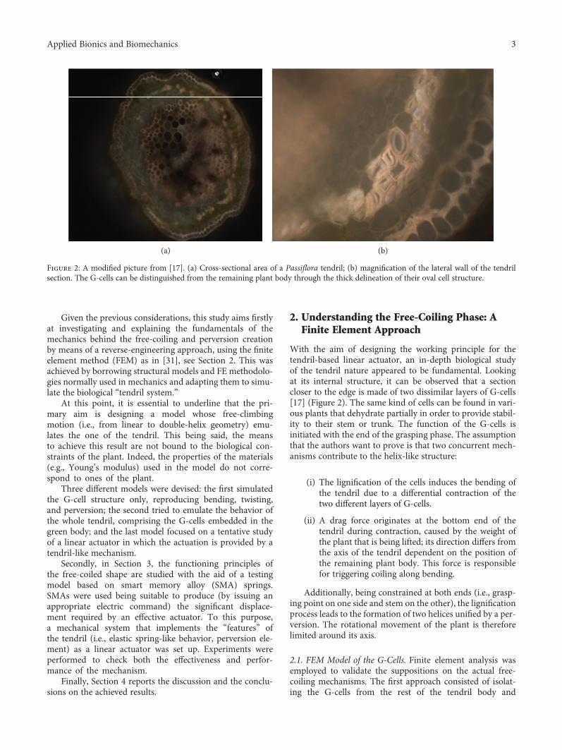
With the aim of designing the working principle for thetendril-based linear actuator, an in-depth biological studyof the tendril nature appeared to be fundamental. Lookingat its internal structure, it can be observed that a sectioncloser to the edge is made of two dissimilar layers of G-cells[17] (Figure 2). The same kind of cells can be found in vari-ous plants that dehydrate partially in order to provide stabil-ity to their stem or trunk. The function of the G-cells isinitiated with the end of the grasping phase. The assumptionthat the authors want to prove is that two concurrent mech-anisms contribute to the helix-like structure:
(i) The lignification of the cells induces the bending ofthe tendril due to a differential contraction of thetwo different layers of G-cells.
(ii) A drag force originates at the bottom end of thetendril during contraction, caused by the weight ofthe plant that is being lifted; its direction differs fromthe axis of the tendril dependent on the position ofthe remaining plant body. This force is responsiblefor triggering coiling along bending.
Additionally, being constrained at both ends (i.e., grasp-ing point on one side and stem on the other), the lignificationprocess leads to the formation of two helices unified by a per-version. The rotational movement of the plant is thereforelimited around its axis.
2.1. FEM Model of the G-Cells. Finite element analysis wasemployed to validate the suppositions on the actual free-coiling mechanisms. The first approach consisted of isolat-ing the G-cells from the rest of the tendril body and
(a) (b)
Figure 2: A modified picture from [17]. (a) Cross-sectional area of a Passiflora tendril; (b) magnification of the lateral wall of the tendrilsection. The G-cells can be distinguished from the remaining plant body through the thick delineation of their oval cell structure.
3Applied Bionics and Biomechanics
simulating their coiling effect only. This is to prove theidea that they could be the driving elements of the entireprocess while the remaining part of the body just movesaccording to them.
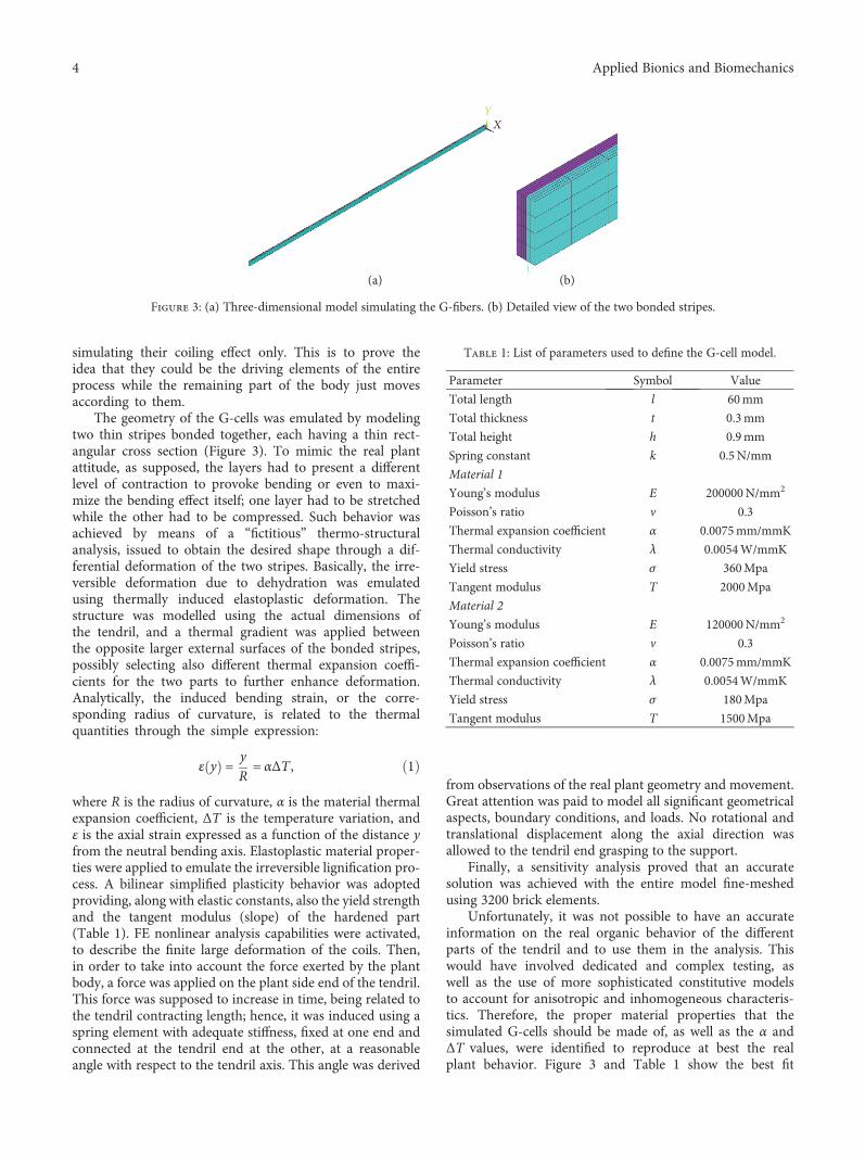
The geometry of the G-cells was emulated by modelingtwo thin stripes bonded together, each having a thin rect-angular cross section (Figure 3). To mimic the real plantattitude, as supposed, the layers had to present a differentlevel of contraction to provoke bending or even to maxi-mize the bending effect itself; one layer had to be stretchedwhile the other had to be compressed. Such behavior wasachieved by means of a “fictitious” thermo-structuralanalysis, issued to obtain the desired shape through a dif-ferential deformation of the two stripes. Basically, the irre-versible deformation due to dehydration was emulatedusing thermally induced elastoplastic deformation. Thestructure was modelled using the actual dimensions ofthe tendril, and a thermal gradient was applied betweenthe opposite larger external surfaces of the bonded stripes,possibly selecting also different thermal expansion coeffi-cients for the two parts to further enhance deformation.Analytically, the induced bending strain, or the corre-sponding radius of curvature, is related to the thermalquantities through the simple expression:
ε y = yR= αΔT , 1
where R is the radius of curvature, α is the material thermalexpansion coefficient, ΔT is the temperature variation, andε is the axial strain expressed as a function of the distance yfrom the neutral bending axis. Elastoplastic material proper-ties were applied to emulate the irreversible lignification pro-cess. A bilinear simplified plasticity behavior was adoptedproviding, along with elastic constants, also the yield strengthand the tangent modulus (slope) of the hardened part(Table 1). FE nonlinear analysis capabilities were activated,to describe the finite large deformation of the coils. Then,in order to take into account the force exerted by the plantbody, a force was applied on the plant side end of the tendril.This force was supposed to increase in time, being related tothe tendril contracting length; hence, it was induced using aspring element with adequate stiffness, fixed at one end andconnected at the tendril end at the other, at a reasonableangle with respect to the tendril axis. This angle was derived
from observations of the real plant geometry and movement.Great attention was paid to model all significant geometricalaspects, boundary conditions, and loads. No rotational andtranslational displacement along the axial direction wasallowed to the tendril end grasping to the support.
Finally, a sensitivity analysis proved that an accuratesolution was achieved with the entire model fine-meshedusing 3200 brick elements.
Unfortunately, it was not possible to have an accurateinformation on the real organic behavior of the differentparts of the tendril and to use them in the analysis. Thiswould have involved dedicated and complex testing, aswell as the use of more sophisticated constitutive modelsto account for anisotropic and inhomogeneous characteris-tics. Therefore, the proper material properties that thesimulated G-cells should be made of, as well as the α andΔT values, were identified to reproduce at best the realplant behavior. Figure 3 and Table 1 show the best fit
Table 1: List of parameters used to define the G-cell model.
Parameter Symbol Value
Total length l 60mm
Total thickness t 0.3mm
Total height h 0.9mm
Spring constant k 0.5N/mm
Material 1
Young’s modulus E 200000N/mm2
Poisson’s ratio v 0.3
Thermal expansion coefficient α 0.0075mm/mmK
Thermal conductivity λ 0.0054W/mmK
Yield stress σ 360Mpa
Tangent modulus T 2000Mpa
Material 2
Young’s modulus E 120000N/mm2
Poisson’s ratio v 0.3
Thermal expansion coefficient α 0.0075mm/mmK
Thermal conductivity λ 0.0054W/mmK
Yield stress σ 180Mpa
Tangent modulus T 1500Mpa
Y
X
(a) (b)
Figure 3: (a) Three-dimensional model simulating the G-fibers. (b) Detailed view of the two bonded stripes.
4 Applied Bionics and Biomechanics
0 2 4 6 8 10
(a)
0 2 4 6 8 10
(b)
0 2 4 6 8 10
(c)
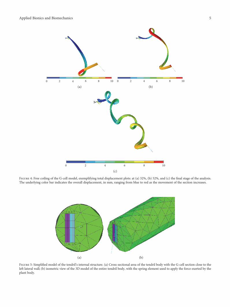
Figure 4: Free coiling of the G-cell model, exemplifying total displacement plots: at (a) 32%, (b) 52%, and (c) the final stage of the analysis.The underlying color bar indicates the overall displacement, in mm, ranging from blue to red as the movement of the section increases.
Y
XZ
(a) (b)
Figure 5: Simplified model of the tendril’s internal structure. (a) Cross-sectional area of the tendril body with the G-cell section close to theleft lateral wall; (b) isometric view of the 3D model of the entire tendril body, with the spring element used to apply the force exerted by theplant body.
5Applied Bionics and Biomechanics

geometry, dimensions, and parameters of the tuned model.It must be underlined that some of these values are physicallydifferent from the ones of the plant as well as of engineeringmaterials and are intended only to reproduce the free-coiling deformation. This was necessary to let the numericalmaterial models suited for metals to behave like an organicG-cell “material.”
The numerical results demonstrated that the simula-tion was capable of reproducing the free-coiling kinematicsreasonably. Figure 4 presents three substeps of the free-coiling phenomenon as simulated. In the last representa-tion, the perversion is clearly visible while in the others,the progressive bending and twisting of the structure canbe observed. The formation of the perversion is correctlyinduced by the constraints applied on both ends andappears roughly at half of the tendril length. It representsthe meeting point of the two helices with opposite rota-tional directions. Furthermore, it appears that the increasein the thermal coefficient causes an increase in the numberof the formed coils, which can be therefore controlledthrough this parameter.
2.2. FEM Model of the Entire Tendril Body. In order to set upa simulation of the full tendril, further research was needed toinclude the “passive” part of the plant into the previous G-cellfree-coiling simulation. Consequently, the G-fibers werepositioned on one side of the tendril and enclosed in acylinder-like envelope simulating the green part of the tendrilitself, in accordance to what is observed in Figure 2. Figure 5shows the actual model. The geometry of the meshed ele-ments consisted of bricks and tetrahedra, for the G-cellsand the remaining tendril body, respectively.
The choice of the material of the green body played asignificant role here. By assigning this part of the tendrilthe appropriate elastic properties, it was possible to mimicthe coiling phenomenon with the G-cells being the activesection and the envelope being the passive one. To granthigh elasticity to the body surrounding the G-cells, whichundergoes very large deformations without lignification, ahyperelastic material model (the widely used one proposedby Mooney and Rivlin) was adopted. The model was againsuccessfully tuned to trigger the coiling phenomenon cor-rectly. All material constants relative to this second modelare reported in Table 2.
It can be observed that the application of the cylindri-cal envelope representing the tendril body, though less stiffthan the G-cells made partially, has an influence on thefinal behavior (Figure 6): under the same loading condi-tions, the complete tendril model showed less pronouncedcoils (and also less coils) than the G-cell-only model.Causes of this effect are several. On the one hand, theforce applied on the structure end is now also partiallyinvolved in dragging the red body such that its twistingeffect is therefore reduced. Secondly, the increase in theamount of material acts as a resistant factor which partiallyinhibits coiling.
2.3. FEM Model of a Tendril-Inspired Linear Actuator. Withthe aim of investigating and exploring the feasibility of a
tendril-inspired linear actuator, an additional simulationwas devised. In this case, the major obstacle consisted ofperforming the analysis by applying the force acting onone end of the tendril along the actuation axis, insteadof being directed out of the plane as before (as in the realplant). To achieve this, the boundary conditions weremodified starting from the models previously described:on one side, all the degrees of freedom (DoFs) were con-strained while on the other side, only the movement alongthe actuation axis was allowed. The force promoting thefree-coiling effect, applied at the free translational DoF ofthe tendril end, was distributed uniformly on the entirecross-sectional area. The last modeling step of this analysiswas necessary to induce twisting as desired, consisting ofintroducing a minor irregularity in the motion of the ten-dril. Indeed, a rotation of 0.5 degrees was applied on thenonfixed end of the tendril in order to facilitate coiling.This was necessary because the force which helped twistno longer acts out of axis as before, in the linear actuator.In an actual system, this minor rotation could be intro-duced on purpose to facilitate twisting. The new parame-ters of the linear actuator model are finally provided inTable 3.
Figure 7 shows the output of this last simulation. A line isplotted to help the visualization of the axis and of the linearmovement of the tendril body. As the main result, it can bestated that the free-coiling “mechanism,” constrained to alinear axis, is nevertheless present and still manifests its
Table 2: List of parameters of the entire tendril body model.
Parameter Symbol Value
Total length l 60mm
Total thickness t 0.3mm
Total height h 0.9mm
Spring constant k 0.5N/mm
Material 1
Young’s modulus E 200000N/mm2
Poisson’s ratio v 0.3
Thermal expansion coefficient α 0.0015mm/mmK
Thermal conductivity λ 0.0054W/mmK
Yield stress σ 360Mpa
Tangent modulus T 2000MPa
Material 2
Young’s modulus E 120000N/mm2
Poisson’s ratio v 0.3
Thermal expansion coefficient α 0.0015mm/mmK
Thermal conductivity λ 0.0054W/mmK
Yield stress σ 180MPa
Tangent modulus T 1500MPa
Material 3
Mooney-Rivlin hyperelastic table
C10 0.0275
C01 0.13077
C11 0.68026
d 0.048694
6 Applied Bionics and Biomechanics

peculiar features (i.e., generation of coils, perversion, andcontraction). Moreover, confirming one of the key featuresof the natural tendril, torsion is not present at the simulatedtendril linear actuator ends, given the balancing effect of thetwo halves connected by means of the perversion. It seemstherefore possible to exploit free coiling advantageously, todesign an actuator of a mechanical system.
3. Experimental Model of a Tendril-Like LinearActuator
The FE analysis of the previous section demonstrated tobe effective in providing an understanding of the deforma-tion mechanisms of the tendril and in suggesting a possi-ble utilization of the underlying functioning principles.Nevertheless, a thermally induced actuation mechanism(besides relying on adapted material constants) wouldnot be practical as a real-world application. Hence, to rep-licate the tendril model in an actual testing structure
(prior to thinking at a true prototype), a feasible solutionbased on similar principles highlighted by the FEMevaluation had to be individuated. Eventually, the authorsfound a promising choice in the use of SMA springs[32]. SMAs have been constantly present in various engi-neering fields for the past few years, because of their lowmaintenance cost, corrosion resistance, and lightweightstructure [33, 34]. The capability of this material relieson being able to “remember” the shape that has beenimposed to it and return to it, even after strong deforma-tions, with the application of specific stimuli (e.g.,mechanical or thermal). In fact, being triggered with anappropriate electric stimulus, the SMAs react in a way thatit will be proven to be suitable for the scope. In the fol-lowing, proper SMA springs made of nickel-titanium(Niti) are used to devise and study a linear actuatorinspired by the tendril’s free-coiling effect, by followingthe approach in [6, 8] and by taking advantage of thesuggestions and findings from the previous simulations.
0 1 2 3 4 5 6 7 8 9
XY
Z
(a)
0 1 2 3 4 5 6 7 8 9
XY
Z
(b)
0 1 2 3 4 5 6 7 8 9
Y
X Z
(c)
Figure 6: Free coiling of the entire tendril model, exemplifying total displacement plots: at (a) 32%, (b) 52%, and (c) the final stage. Theunderlying color bar indicates the overall displacements, in mm.
7Applied Bionics and Biomechanics

More in details, as observed, in the advanced free-coiling phase, the tendril was considered at a global leveltwo parts which contract and do not rotate between eachother due to the presence of a peculiar joining element(the perversion) and the constraints at the ends. The typ-ical mechanical element which contracts allowing largedeformations may be a spring. To obtain a spring-likecontraction starting from the inside of the material (thisis crucial) as in the tendril, SMA springs can be profitablyused and were therefore selected. In addition, a linearspring behavior, though different from the nonlinear oneof the real tendril, might represent a future advantage incontrolling a real actuator. Such experimental model canbe designed to investigate the effectiveness of the doublehelical shape of the free-coiled tendril. Once more, the rele-vance of the geometrical appearance is put in foreground,and possible discordances with the internal structure of theactual tendril are neglected.
3.1. Design of the Testing Structure. The experimentalmodel is composed of two NiTi springs, with oppositerotational directions, assembled in series and unified by alinear segment representing the perversion. As previouslystated, in such a manner, a simplified version of the ten-dril where the perversion and the helices are already pres-ent was reproduced. The system was constrained at oneend to a fixed crosshead of a rigid frame, while, on theother end, a vertical constant load (weight) was applied to amoving crosshead. Torsion at the extremities was visuallyevaluated while the axial displacement of the moving cross-head was measured through a rigid ruler fixed on the frame.The diameter of the springs and of their wire measure isrespectively 6mm and 0.35mm. Their resistivity is82μOhm/cm at the high-temperature state (76μOhm/cm
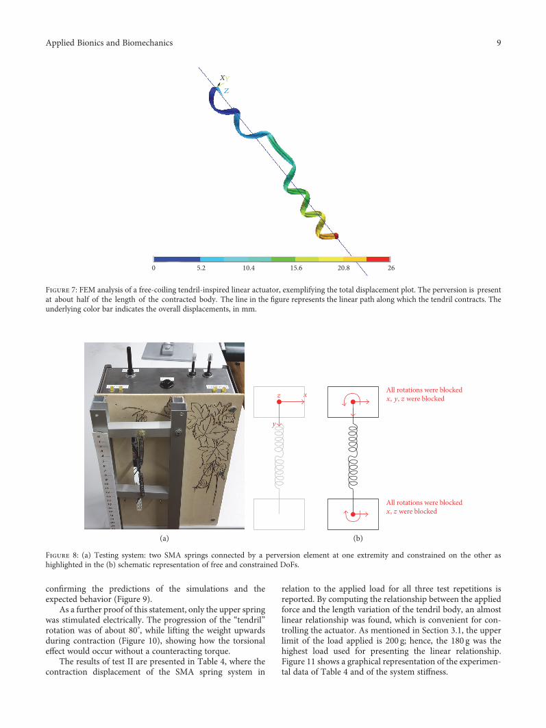
at the low-temperature stage). To stimulate SMA springswith an electrical current, a piloting circuit was designedand tuned in order to supply the proper amount of electricity.In particular, the circuit needed to provide about 2A toactuate the springs with the chosen characteristics. Thelayout of the arrangement is shown in Figure 8(a). Onone side, the two SMA springs are connected togetherand, on the other side, are constrained in their motionin order to mimic the real tendril condition. The upperconstraint representing the contact-coiling point of the ten-dril limits all DoFs, that is, the aluminium rod is blocked.The constraint at the bottom allows a translation movementonly (i.e., elongation and contraction). A graphical illustra-tion of the constrained and free degrees of freedom is givenin Figure 8(b).
Different tests were devised in order to check the poten-tial of such mechanism to mimic the behavior of the tendril.SMA springs were mounted with an opposite twisting direc-tion, and in the first phase (i.e., test I), different stimulationswere applied to estimate the torsional effect at the perversionlevel and at the blocked extremities.
In the second phase (i.e., test II), the contractionlength of the SMA springs and the applied loads weremeasured during the experiments, to evaluate the stiffnessof the system. The applied testing procedure for test II canbe summarized in the following steps, which were repeatedfor different loads:
(i) Application of the load at the bottom rod end (rangefrom 20 g to 200 g)
(ii) Stimulation with an electric current (2A, 12.5V) toinduce the contraction of the SMA springs
(iii) Measurement of the system displacement
(iv) Pausing for 180 s in order to allow the springs to cooldown (i.e., not to influence further measurements).
The minimum applied load was 20 g; for smallervalues, no appreciable spring displacement was noticed;the upper limit was defined so that the NiTi springs arenot damaged (i.e., by applying loads higher than 200 g,the springs may undergo a permanent elongation); theload increment was set to 20 g to collect a significantamount of data. The process was repeated three timesper each applied weight, in order to ensure the necessaryrepeatability of the measurements.
3.2. Results and Observations. Observations made during testI experiments, concerning the motion of the prototype, leadto some considerations on the crucial importance of the per-version. When a single spring lifts a load, a torque is experi-enced, while by connecting two springs with oppositerotational directions, two opposite torques are created andthey cancel one another out. The presence of the perversiontherefore imposes an almost pure linear movement of thetendril body when lifting loads. Indeed, when the series ofsprings was actually stimulated, they contracted and the loadwas lifted showing no appreciable rotational movement,
Table 3: List of parameters of the linear actuator model.
Parameter Symbol Value
Total length l 60mm
Total thickness t 0.3mm
Total height h 0.9mm
Spring constant k 3N/mm
Material 1
Young’s modulus E 200000N/mm2
Poisson’s ratio v 0.3
Thermal expansion coefficient α 0.0075mm/mmK
Thermal conductivity λ 0.0054W/mmK
Yield stress σ 360MPa
Tangent modulus T 2000Mpa
Material 2
Young’s modulus E 120000N/mm2
Poisson’s ratio v 0.3
Thermal expansion coefficient α 0.0075mm/mmK
Thermal conductivity λ 0.0054W/mmK
Yield stress σ 180MPa
Tangent modulus T 1500MPa
8 Applied Bionics and Biomechanics
confirming the predictions of the simulations and theexpected behavior (Figure 9).
As a further proof of this statement, only the upper springwas stimulated electrically. The progression of the “tendril”rotation was of about 80°, while lifting the weight upwardsduring contraction (Figure 10), showing how the torsionaleffect would occur without a counteracting torque.
The results of test II are presented in Table 4, where thecontraction displacement of the SMA spring system in
relation to the applied load for all three test repetitions isreported. By computing the relationship between the appliedforce and the length variation of the tendril body, an almostlinear relationship was found, which is convenient for con-trolling the actuator. As mentioned in Section 3.1, the upperlimit of the load applied is 200 g; hence, the 180 g was thehighest load used for presenting the linear relationship.Figure 11 shows a graphical representation of the experimen-tal data of Table 4 and of the system stiffness.
(a)
z
y
xAll rotations were blockedx, y, z were blocked
All rotations were blockedx, z were blocked
(b)
Figure 8: (a) Testing system: two SMA springs connected by a perversion element at one extremity and constrained on the other ashighlighted in the (b) schematic representation of free and constrained DoFs.
0 5.2 15.6 20.8 2610.4
XY
Z
Figure 7: FEM analysis of a free-coiling tendril-inspired linear actuator, exemplifying the total displacement plot. The perversion is presentat about half of the length of the contracted body. The line in the figure represents the linear path along which the tendril contracts. Theunderlying color bar indicates the overall displacements, in mm.
9Applied Bionics and Biomechanics

The best-fit linear regression of the collected data iscalculated as follows:
d x = −0 035x + 59 311, 2
where d is the contraction length in millimeters and x is theapplied weight in grams.
Table 4: Experimental load-displacement data.
Applied weight (g)Contraction length (mm)
Trial 1 Trial 2 Trial 3
20 58 57 59
40 57 59 58
60 56 56 57
80 57 58 56
100 56 56 56
120 56 57 56
140 54 54 56
160 54 54 54
180 53 53 54
200 50 50 51Mass (g)
20 40 60 80 100 120 140 160 180
Con
trac
tion
leng
th (m
m)
40
45
50
55
60
65
70
75
80
Trial 1Trial 2
Trial 3Linear fit
Figure 11: Linear regression of load-displacement experimentaldata (the different shaped dots represent the results of threerepetitions of the test).
(a) (b) (c)
Figure 10: Test I: twisting effect, one spring only stimulated: (a) initial configuration; (b) the spring is driven and it starts rotating while liftingthe weight; (c) at a visual inspection, the perversion in its final position has experienced a rotation of about 80°, as indicated by the red arrow.
(a) (b) (c)
Figure 9: Test I: zero twist proof, both springs stimulated: (a) initial configuration; (b) spring contraction; (c) spring at its final minimumlength. No angular displacement of the perversion has been observed during the motion.
10 Applied Bionics and Biomechanics

4. Conclusions
The free-coiling mechanism of a tendril-bearer climbingplant was investigated, and subsequently, the occurringgeometrical mutation was replicated and characterized.The findings were used to devise a conceptual linear actu-ator. Previous theoretical studies on the nature of tendrils[8, 17] were reconsidered and extended by means of FEanalyses of the tendril behavior. Investigations about thespecific biological structure of the plant as well as theanalysis of the effects of its peculiar degrees of freedomswere fundamental to set up the numerical models. Morein detail, starting from the first modeling of the G-cellfree-coiling, the simulation evolved into the emulation ofthe free coiling of the entire tendril body.
Even though the properties assigned to the G-cells as wellas to the elastic layer were not faithfully representing thebiological behavior of the tendril’s internal structure, never-theless, the model provided a successful description of themotion during the free-coiling phase. A further numericalstudy explored the conceptual possibility of realizing a linearactuator based on the same biomechanisms. The researchthen focused on the reproduction of a real conceptual model.With the aid of SMAs, the process of lifting a weight usingfree coiling was replicated in lab, realizing an equivalent“mechanical” tendril. The relation between contractionlength of the system and the applied force was found tomaintain an almost linear relationship. Furthermore, theinfluence of the perversion on the tendril motion wasrevealed and proved: it ensures that the tendril-likesystem experiences no torque while uplifting loads.
Conflicts of Interest
The authors declare that there are no conflicts of interestregarding the publication of this paper.
Acknowledgments
The authors want to express their gratitude to E. Galante,L. L. Battellino, and F. Iob, for their help in implementingthe testing device piloting circuit.
References
[1] B. Mazzolai and S. Mancuso, “Smart solutions from the plantkingdom,” Bioinspiration and Biomimimetics, vol. 8, no. 2,article 020301, 2013.
[2] C. Darwin, The Movements and Habits of Climbing Plants,Appleton, New York, 1876.
[3] C. Darwin, On the Movements and Habits of Climbing Plants,John Murray, London, 1865.
[4] S. Isnard and W. Silk, “Moving with climbing plants fromCharles Darwin’s time into the 21st century,” AmericanJournal of Botany, vol. 96, no. 7, pp. 1205–1221, 2009.
[5] Y. Bar-Cohen, Biomimetics Nature-Based Innovation, CRCpress, Taylor and Francis Group, Boca-Raton, FL, USA, 2012.
[6] R. Vidoni, T. Mimmo, C. Pandolfi, F. Valentinuzzi, and S.Cesco, “SMA bio- robotic mimesis of tendril-based climbingplants: first results,” in Proceedings of the 16th International
Conference on Advanced Robotics - ICAR 2013, Montevideo,Uruguay, November 2013.
[7] C. Pandolfi, T. Mimmo, and R. Vidoni, “Climbing plants, anew concept for robotic grasping,” Living Machines 2013,LNAI 8064, pp. 418–420, 2013.
[8] R. Vidoni, T. Mimmo, and C. Pandolfi, “Tendril-basedclimbing plants to model, simulate and create bio-inspiredrobotic systems,” Journal of Bionic Engineering, vol. 12, no. 2,pp. 250–262, 2015.
[9] C. Darwin and F. Darwin, The Power of Movements in Plants,Appleton, New York, 1880.
[10] M. J. Jaffe and A. W. Galston, “The physiology of tendrils,”Annual Review of Plant Physiology, vol. 19, pp. 417–434,1968.
[11] J. Von Sachs, Lectures on the Physiology of Plants, TheClarendon Press, Oxford, 1888.
[12] S. Mugnai, E. Azzarello, E. Masi, C. Pandolfi, and S. Mancuso,“Nutation in plants,” in Rhythms in Plants: Phenomenology,Mechanisms and Adaptative Significance, S. Mancuso and S.Shabala, Eds., pp. 77–90, Springer-Verlag, Berlin Heidelberg,2007.
[13] L. C. Trevisan Scorza and M. Carnier Dornelas, “Plants on themove. Toward commonmechanisms governing mechanically-induced plant movements,” Plant Signaling and Behavior,vol. 6, no. 12, pp. 1979–1986, 2011.
[14] M. Stolarz, “Circumnutation as a visible plant action andreaction,” Plant Signaling & Behavior, vol. 4, no. 5,pp. 380–387, 2009.
[15] K. C. Vaughn and A. J. Bowling, “Biology and physiologyof vines,” Horticultural Reviews, vol. 38, 2011.
[16] A. J. Bowling and K. C. Vaughn, “Gelatinous fibers arewidespread in coiling tendrils and twining plants,” AmericanJournal of Botany, vol. 96, no. 4, pp. 719–727, 2009.
[17] S. J. Gerbode, J. Sharon, J. R. Puzey, A. G. McCormick, and L.Mahadevan, “How the cucumber tendril coils and overwinds,”Science, vol. 337, no. 6098, pp. 1087–1091, 2012.
[18] A. Goriely and M. Tabor, “Spontaneous helix hand reversaland tendril perversion in climbing plants,” Physical ReviewLetters, vol. 80, no. 7, p. 1564, 1998.
[19] T. McMillen and A. Goriely, “Tendril perversion inintrinsically curved rods,” Journal of Nonlinear Science,vol. 12, pp. 241–281, 2002.
[20] H. J. Zhou and Z. C. Ou-Yang, “Spontaneous curvature-induced dynamical instability of Kirchhoff filaments: applica-tion to DNA kink deformations,” The Journal of ChemicalPhysics, vol. 110, pp. 1247–1251, 1999.
[21] P. E. S. Silva, J. L. Trigueiros, A. C. Trindade et al., “Perversionswith a twist,” Scientific Reports, vol. 6, article 23413, 2016.
[22] S. Hirose, Biologically Inspired Robots, Oxford UniversityPress, Oxford, 1993.
[23] G. Robinson and J. B. C. Davies, “Continuum robots - astate of the art,” in Proceedings of the IEEE InternationalConference on Robotics and Automation, pp. 2849–2854,Detroit, USA, May 1999.
[24] B. A. Jones and I. D. Walker, “Kinematics for multisectioncontinuum robots,” IEEE Transaction on Robotics, vol. 22,p. 1, 2006.
[25] J. S. Mehling, M. A. Diftler, M. Chu, and M. Valvo,“A minimally invasive tendril robot for in-space inspection,”in The First IEEE/RAS-EMBS International Conference on
11Applied Bionics and Biomechanics

Biomedical Robotics and Biomechatronics, 2006. BioRob2006, pp. 690–695, Pisa, Italy, February 2006.
[26] I. D. Walker, “Biologically inspired vine-like and tendril-likerobots,” in 2015 Science and Information Conference (SAI),pp. 714–720, London, UK, July 2015.
[27] S. Kaluvan, C. Y. Park, and S. B. Choi, “Bio-inspired device:a novel smart MR spring featuring tendril structure,” SmartMaterials and Structures, vol. 25, no. 1, article 01LT01,2016.
[28] M. Wang, B.-P. Lin, and H. Yang, “A plant tendril mimic softactuator with phototunable bending and chiral twistingmotion modes,” Nature Communications, vol. 7, article13981, 2016.
[29] P. Chen, Y. Xu, S. He et al., “Hierarchically arranged helicalfibre actuators driven by solvents and vapours,” Nature Nano,vol. 10, no. 12, pp. 1077–1083, 2015.
[30] A. R. Studart and R. M. Erb, “Bioinspired materials thatself-shape through programmed microstructures,” SoftMatter, vol. 10, no. 9, pp. 1284–1294, 2014.
[31] Z. Chen, “Shape transition and multi-stability of helicalribbons: a finite element method study,” Archive of AppliedMechanics, vol. 85, pp. 331–338, 2015.
[32] M. Zrinyi, “Intelligent polymer gels controlled by magneticfields,” Colloid & Polymer Science, vol. 278, no. 2, pp. 98–103, 2000.
[33] D. J. Hartl and D. C. Lagoudas, “Characterization and 3-Dmodeling of Ni60Ti SMA for actuation of a variable geom-etry jet engine chevron,” in Proceedings of SPIE, Conferenceof Sensors and Smart Structures Technologies for Civil,Mechanical, and Aerospace Systems, San Diego, CA, 2007.
[34] J. H. Kyung, B. G. Ko, Y. H. Ha, and G. J. Chung, “Design of amicrogripper for micromanipulation of microcomponentsusing SMA wires and flexible hinges,” Sensors and Actuatorsa, vol. 141, pp. 144–150, 2008.
12 Applied Bionics and Biomechanics

RoboticsJournal of
Hindawi Publishing Corporationhttp://www.hindawi.com Volume 2014
Hindawi Publishing Corporationhttp://www.hindawi.com Volume 2014
Active and Passive Electronic Components
Control Scienceand Engineering
Journal of
Hindawi Publishing Corporationhttp://www.hindawi.com Volume 2014
International Journal of
RotatingMachinery
Hindawi Publishing Corporationhttp://www.hindawi.com Volume 2014
Hindawi Publishing Corporation http://www.hindawi.com
Journal of
Volume 201
Submit your manuscripts athttps://www.hindawi.com
VLSI Design
Hindawi Publishing Corporationhttp://www.hindawi.com Volume 201
Hindawi Publishing Corporationhttp://www.hindawi.com Volume 2014
Shock and Vibration
Hindawi Publishing Corporationhttp://www.hindawi.com Volume 2014
Civil EngineeringAdvances in
Acoustics and VibrationAdvances in
Hindawi Publishing Corporationhttp://www.hindawi.com Volume 2014
Hindawi Publishing Corporationhttp://www.hindawi.com Volume 2014
Electrical and Computer Engineering
Journal of
Advances inOptoElectronics
Hindawi Publishing Corporation http://www.hindawi.com
Volume 2014
The Scientific World JournalHindawi Publishing Corporation http://www.hindawi.com Volume 2014
SensorsJournal of
Hindawi Publishing Corporationhttp://www.hindawi.com Volume 2014
Modelling & Simulation in EngineeringHindawi Publishing Corporation http://www.hindawi.com Volume 2014
Hindawi Publishing Corporationhttp://www.hindawi.com Volume 2014
Chemical EngineeringInternational Journal of Antennas and
Propagation
International Journal of
Hindawi Publishing Corporationhttp://www.hindawi.com Volume 2014
Hindawi Publishing Corporationhttp://www.hindawi.com Volume 2014
Navigation and Observation
International Journal of
Hindawi Publishing Corporationhttp://www.hindawi.com Volume 2014
DistributedSensor Networks
International Journal of