a-e performance spec i f ication · pdf fileperformance spec i f ication ... pressure of 4.0...
TRANSCRIPT
Document ID: SPC-358 Revision ID: 0 Effective Date: April 4, 2002
A-E PERFORMANCE SPEC I F ICATION
PROJECT FILE NO. 021052
OU 7-10 GLOVEBOX EXCAVATOR METHOD PROJECT
Retrieval Confinement Structure
Prepared for: U.S. Department of Energy Idaho Operations Office Idaho Falls, Idaho
Idaho National Engineering \/ and En~ironmental Laboratom
Form 41 2.1 4 07/24/2001 Rev. 03

412.15 03/14/2002 Rev. 03
8. Type or Printed Name
Signature
DOCUMENT MANAGEMENT CONTROL SYSTEM (DMCS) DOCUMENT APPROVAL SHEET
9. 9. IO. RIA Date Organization/
Discipline
1. Document Identifier: SPC-358 2. Project File No. (optional): 021052 3. Revision No.: 0
4. Document Title:
5. Author: David L. Stephens, P. E. 5. Owner: Scott A. Jensen, P. E.
7. Comments:
OU 7-1 0 GLOVEBOX EXCAVATOR METHOD PROJECT Retrieval Confinement Structure
Steven A, Davies,.P. E. I A
Scott A. Jensen, P. E. I A
Stephanie L. A d a d , P. E. I R
11. Document Control Release Signature: I
YAG 711 0 Project - 31 EO
'roject Engineer
YAG 711 0 Project - 31 EO
jtructural Design Lead Engineer
YAG 711 0 Project - 31 EO
<CS Structural Design
Iesign Engineering - 6770
ndependent Peer Reviewer
Iesign Engineering - 6770
ingineering Group Supervisor Reviewer
RECORDSMANAGEMENT
12. Does document contain sensitive, unclassified information? Yes 0 No [XI If Yes, what category:
13. Can document be externally distributed? Yes No c] 14. Area Index Code: Area 098 Type 0671 SSC ID: RCS
15. Uniform File Code: 6400 16. Disposition Authority: ENVI-k-2-b Record Retention Period: EOP + 25 years
17. For QA Records Classification Only: Lifetime Nonpermanent 0 Permanent
Item or activity to which the QA Records apply:
18. NRC Related? Yes 0 No 19. Periodic Review Frequency: N/A B, 5 years 0, or Other

Performance OU 7-10 GLOVEBOX Specification EXCAVATOR METHOD
PROJECT Retrieval Confinement Structure
1 . SCOPE .............................................................................................................................. 1
Identifier: SPC-358 Revision: 0 Page: ii o f v
1.1 General ................................................................................................................... 1
1.2 Work Included ......................................................................................................... 1
1.2.1 Design Phase ........................................................................... 1 1.2.2 Fabrication Phase .................................................................................. 1 1.2.3 Installation Phase .................................................................................. 1
1.3 Work Not Included .................................................................................................. 2
1.3.1 Erection ......................................................................................................... 2 1.3.2 Final Structure Testing ................................................................................... 2
2 . QUALIFICATIONS .......................................................................................................... 2
2.1 General ................................................................................................................... 2
APPLICABLE CODES, PROCEDURES. AND REFERENCES ....................................... 3 3 .
3.1 National Design Codes and Material Specifications ................................................. 3
3.2 Drawings ................................................................................................................. 4
4 . SUBMITTALS .................................................................................................................. 4
4.1 General ................................................................................................................... 4
4.2 Qualifications .......................................................................................................... 6
4.3 Design Calculations ................................................................................................. 6
4.4 Peer Review of Design Calculations ........................................................................ 6
4.5 Shop Drawings ........................................................................................................ 7
4.6 Erection Drawings ................................................................................................... 7
4.7 Erection Instructions ................................................................................................ 7
4.8 Welder Qualifications .............................................................................................. 7
4.9 Weld Procedures ..................................................................................................... 7
4.10 Nondestructive Examination Procedures ................................................................. 7
4.1 1 Inspector Qualifications .......................................................................................... 8
4.12 Certificates of Conformance ................................................................................... 8

OU 7-10 GLOVEBOX EXCAVATOR METHOD
PROJECT Retrieval Confinement Structure
Performance Specification
Identifier: SPC-3 58 Revision: 0 Page: iii of v
4.13 Spares and Replacement Parts ................................................................................. 8
4.14 Manufacturing. Inspection. and Test Plan ............................................................... 8
4.15 Inspection Report ................................................................................................... 8
4.16 Mockup Study Report ............................................................................................. 8
4.17 Packaging. Handling and Shipping Instructions ...................................................... 9
4.18 Material Safety Data Sheets .................................................................................... 9
4.19 Operation And Maintenance (O&M) Manuals ........................................................ 9
5 . DESIGN ............................................................................................................................ 9 . . 5.1 General Design Criteria ............................................................................................ 9
5.2 Mockup Study ......................................................................................................... 9
5.3 Dimensions and Layout ......................................................................................... 10 . . 5.4 Seismic ................................................................................................................. 10
5.5 RoofLoads ............................................................................................................ 10
5.6 Collateral Loads .................................................................................................... 10
5.7 Internal Pressure Load ........................................................................................... 10 . . 5.8 Additional Design Criteria ..................................................................................... 11
5.9 Special Inspection and Test Plan ............................................................................ 11
....................................................................... 6 . MANUFACTURING AND ASSEMBLY 12
6.1 General ................................................................................................................. 12
6.2 Materials ............................................................................................................... 12
6.2.1 6.2.2 6.2.3 6.2.4 6.2.5 6.2.6 6.2.7 6.2.8 6.2.9 6.2.10
Stainless Steel Panels Including Sheet and Strip Material ........................ 12 Shapes and Bars for Frames and Structural Members Personnel and Overburden Transfer Doors and Door Coiling Door ............................................................................... Windows and Portholes in Confinement Walls or Ro Windows in Personnel Doors .................................................................. 13 Joint Tape .............................. ...................................... 13 Silicone Sealant ................................................ Sealing Gaskets ........................................................................... Panel Attachment &vets .............................................................
. .
. .

Performance OU 7-10 GLOVEBOX Specification EXCAVATOR METHOD
PROJECT Retrieval Confinement Structure
6.2.1 1 6.2.12
Bolts, Nuts, Studs, and Washers for Attachments and Accessories.. . . . . . . . . .13 High Strength Bolts, Nuts, and Washers for Structural Framing Members13
Identifier: SPC-358 Revision: 0 Page: iv of v
. . 6.3 Fabrication . . . . . . . . . . . . . . . . . . . . . . . . . . . . . . . . . . . . . . . . . . . . . . . . . . . . . . . . . . . . . . . . . . . . . . . . . . . . . . . . . . . . . . . . . . . . . . . . . . . . . . . . . . . .14
6.3.1 Welding ................................................... ............................. 14 6.3.2 Painting ..................................................... 6.3.3 Panels a ..................................................... 6.3.4 Fabricat ............................................... 15 6.3.5 ............................................... 15 Material Traceability.. . . . . . . . . . . . .
7. QUALITY ASSURANCE ............................................................................................... 15
7.1 General ................................................................................................................. 15 . . 7.2 Nondestructive Examinations . . . . . . . . . . . . . . . . . . . . . . . . . . . . . . . . . . . . . . . . . . . . . . . . . . . . . . . . . . . . . . . . . . . . . . . . . . . . . . . .15
7.3 Procurement Document Control.. . . . . . . . . . . . . . . . . . . . . . . . . . . . . . . . . . . . . . . . . . . . . . . . . . . . . . . . . . . . . . . . . . . . . . . . . . . .15
7.4 Document Control ................................................................................................. 15
7.5 Measuring and Test Equipment . . . . . . . . . . . . . . . . . . . . . . . . . . . . . . . . . . . . . . . . . . . . . . . . . . . . . . . . . . . . . . . . . . . . . . . . . . . . .15
7.6 Inspection Status . . . . . . . . . . . . . . . . . . . . . . . . . . . . . . . . . . . . . . . . . . . . . . . . . . . . . . . . . . . . . . . . . . . . . . . . . . . . . . . . . . . . . . . . . . . . . . . . . . .16
7.7 Nonconforming Items/ Corrective Actions.. . . . . . . . . . . . . . . . . . . . . . . . . . . . . . . . . . . . . . . . . . . . . . . . . . . . . . . . . . . .16
7 .8 Quality Assurance Records.. . . . . . . . . . . . . . . . . . . . . . . . . . . . . . . . . . . . . . . . . . . . . . . . . . . . . . . . . . . . . . . . . . . . . . . . . . . . . . . . . . .16
8 . PACKAGING AND SHIPPING.. . . . . . . . . . . . . . . . . . . . . . . . . . . . . . . . . . . . . . . . . . . . . . . . . . . . . . . . . . . . . . . . . . . . . . . . . . . . . . . . . . . . .16
8.1 Piece Marking and Identification . . . . . . . . . . . . . . . . . . . . . . . . . . . . . . . . . . . . . . . . . . . . . . . . . . . . . . . . . . . . . . . . . . . . . . . . . . .16
8.2 Packaging .............................................................................................................. 16
8.3 Material Delivery . . . . . . . . . . . . . . . . . . . . . . . . . . . . . . . . . . . . . . . . . . . . . . . . . . . . . . . . . . . . . . . . . . . . . . . . . . . . . . . . . . . . . . . . . . . . . . . . . .16
8.4 Handling ............................................................................................................... 17
APPENDIX A - Vendor Data Schedule
APPENDIX B - Drawings
519888 T-1 Site Map, Area Map and Drawing Index
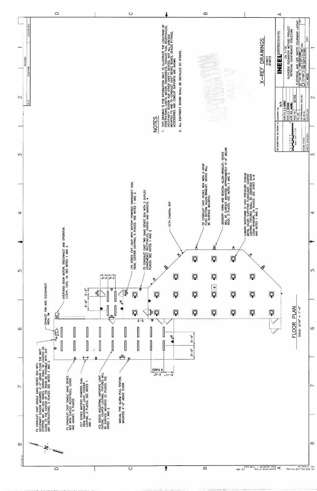
519889 A-1 Floor Plan and Legends
5 19890 A-2 Elevations

Performance OU 7-10 GLOVEBOX Specification EXCAVATOR METHOD
PROJECT Retrieval Confinement Structure
519891 A-3 Views
Identifier: SPC-358 Revision: 0 Page: v o f v
519892 A-4 Views
519893 A-5 Views
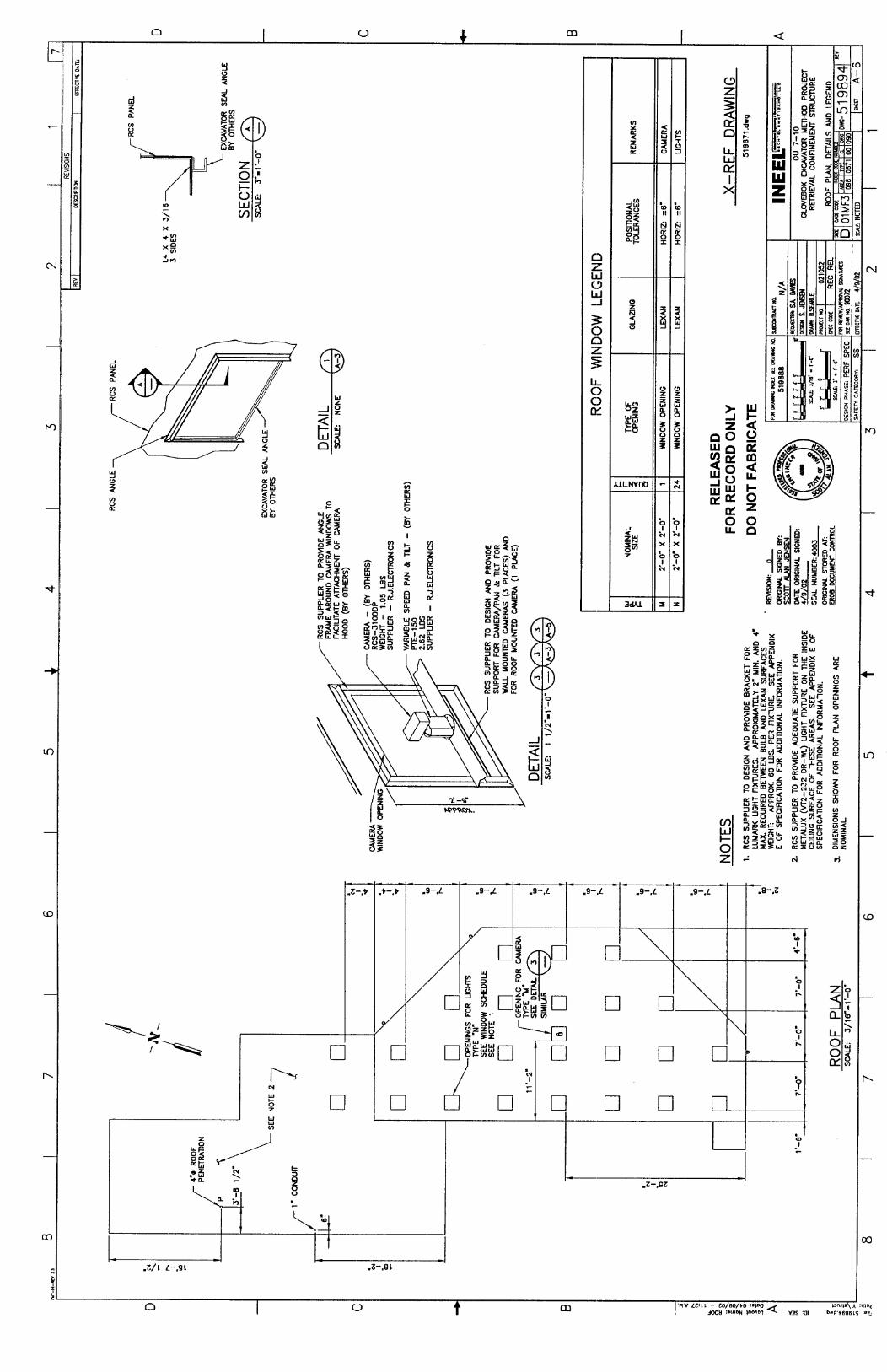
5 19894 A-6 Roof Plan, Details and Legend
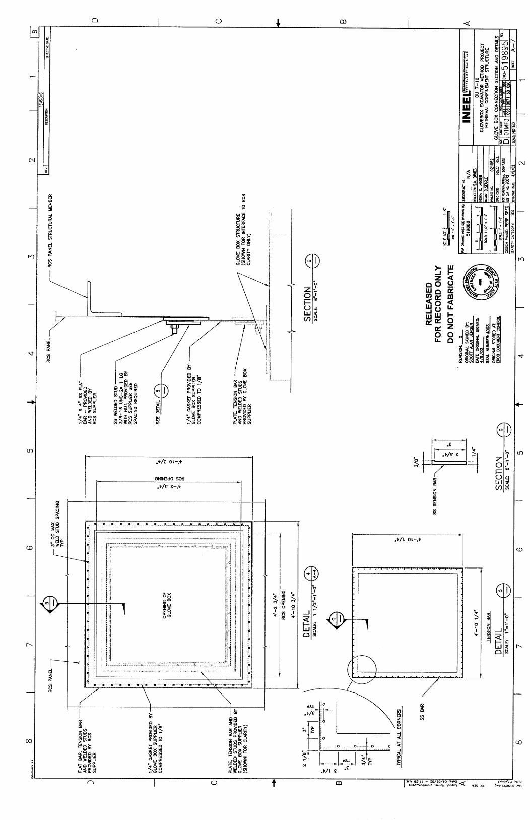
5 19895 A-7 Glove Box Connection Section and Details
APPENDIX C - Penetrations, Attachments, and Interfaces for RCS and Related Structures
APPENDIX D - Fire Protection Piping Layout Drawings (For Information Only)
FP-4 WES Lower
FP-8 RCSPlan
APPENDIX E - Proposed Lighting Fixture Vendor Cut Sheets and Layout Drawing
APPENDIX F - Retrieval Confinement Structure Analysis and Loading Criteria (For Information Only)
APPENDIX G - Form 540.04, Certificate of Conformance

EXCAVATOR METHOD PROJECT
Retrieval Confinement Structure
Specification Revision: 0 Page: 1 of 17
1. SCOPE
1.1 General
The work includes design, fabrication, inspection, testing, shipping, handling, and erection supervision of a complete modular panel retrieval confinement structure (RCS) for the OU7- 10 Glovebox Excavator Method Project, as shown on the attached drawings. Included are design and fabrication of personnel doors, windows, portholes, interface elements, and all associated hardware, seals, and gaskets. Also included are all accessories and items necessary for the scope and intended use and as specified herein. Unless specifically noted otherwise in this specification the acronym RCS will refer to the group of areas shown on the drawings as (RCS, transfer vestibule overburden area, personnel access areas, and personnel monitoring area)
1.2 Work Included
1.2.1 Design Phase
The design of the RCS includes, but is not limited to, the preparation of calculations and drawings.
The deliverables required at the end of the design phase include but are not limited to "D" size shop drawings including electronic files for the drawings, approved design calculations, erection instructions, and peer review certification as described in the "Submittals" section below.
The design phase will be considered complete when all the vendor data items listed in the Section 4, Submittals, have received a "work may proceed" disposition.
1.2.2 Fabrication Phase
The RCS shall be fabricated upon completion of the design phase and shipped to the INEEL for erection. In-plant inspection of the fabrication process shall be made by Bechtel B WXT (BBWI) quality representatives and design engineers, in addition to the inspections performed by the Supplier.
1.2.3 Installation Phases
On-site Supplier support shall be provided for a period of two to three weeks on two separate occasions, separated by approximately six months. First, the confinement Supplier shall provide a full-time installation consultant for a period of approximately three weeks to oversee the erection of the confinement structure. The INEEL Site Stabilization Agreement requires site construction to be done by construction trades with workers supplied by the local trade unions. Therefore, the building will be assembled by local union ironworkers.

EXCAVATOR METHOD PROJECT
Retrieval Confinement Structure
Specification Revision: 0 Page: 2 of 17
Second, the confinement Supplier shall provide a full-time installation consultant for a period of approximately two weeks to oversee the sealing of joints and penetrations. The consultant shall also be present to observe the testing phase following the sealing of the joints and penetrations.
1.3 Work Not Included
1.3.1 Erection
The erection of the RCS is not included in the scope of work included in this specification.
1.3.2 Final Structure Testing
BBWI will be responsible for carrying out the final structure testing. This testing will have at least four phases.
First, the structure shall be pressurized to -0.5 in, water column and subjected to a bubble test (use “Snoop” or equal) at all the panel joints and penetration perimeters. Additional caulk and tape shall be applied as necessary to meet acceptance criteria as follows: No observed bubble of 1 mm diameter or greater in any 10 second period.
Second, a structural and joint seal integrity pressure test up to a maximum negative pressure of 4.0 inches, water column, shall be conducted for the RCS (excludes the transfer vestibule overburden, personnel access, and personnel monitoring areas).
Third, the first pressure test shall be repeated and the impact of the second test on joint seal integrity shall be evaluated.
Fourth, the RCS panel joints and penetration perimeters (excluding the transfer vestibule overburden, personnel access, and personnel monitoring areas) shall be tested with a “smoke pencil” under a positive pressure of 0.5 inch, water column. Additional caulk and tape shall be applied as necessary to meet acceptance criteria as follows: No smoke applied at a joint or penetration is observed as moving under a pressure differential from the inside of the confinement to the outside.
2. QUAL1 FlCATlONS
2.1 General
Supplier shall be regularly engaged in the design and fabrication of modular panel confinement type structures. The confinement supplier shall have at least twelve years experience in designing, manufacturing, and field servicing pre-engineered, modular panel confinements for use in radiological contamination areas. All design work shall be accomplished under the responsible charge of a Professional Engineer registered in the State of Idaho to

Performance OU 7-10 GLOVEBOX Specification EXCAVATOR METHOD
PROJECT Retrieval Confinement Structure
practice civil or structural engineering with at least 5 years experience in the design of this type of structure. All drawings shall be compatible with the latest version of AutoCad and prepared by experienced drafters with at least 2 years experience working on this type of structure. Erection consultation will be performed by a person with at least 10 years experience installing structures of this type.
Identifier: SPC-358 Revision: 0 Page: 3 of 17
3. APPLICABLE CODES, PROCEDURES, AND REFERENCES
3.1 National Design Codes and Material Specifications
AMERICAN INSTITUTE OF STEEL CONSTRUCTION (AISC)
AISC (ASD) Specification for Structural Steel for Buildings-- Allowable Stress Design (ASD)
AMERICAN SOCIETY FOR TESTING AND MATERIALS (ASTM)
A 6
A 36
A 167
A 240
A 276
A 307
A 500
A 529
A 563
A 992
General Requirements For Rolled Steel Plates, Shapes, Sheet Piling, and Bars For Structural Use.
Structural Steel
Stainless Steel and Heat Resisting Chromium Nickel Steel Plate, Sheet, and Strip
Heat-Resisting Steel Plate, Sheet, and Strip For Fusion Welded Unfired Pressure Vessels
Stainless Steel Bars and Shapes
Carbon Steel Bolts and Studs, 60,000 psi Tensile Strength
Standard Specification for Cold-Formed Welded and Seamless Carbon Steel Structural Tubing in Rounds and Shapes
Standard Specification for High-Strength Carbon-Manganese Steel of Structural Quality
Carbon and Alloy Steel Nuts
Steel for Structural Shapes for Use in Building Framing
AMERlCAN SOCIETY OF CIVIL ENGINEERS (ASCE)
ASCE 7-98 Minimum Design Loads for Buildings and Other Structures

EXCAVATOR METHOD PROJECT
Retrieval Confinement Structure
Specification Revision: 0 Page: 4 of 17
AMERICAN WELDING SOCIETY (AWS)
AWS B2.1
AWS D1.1 AWS D1.6
Specification for Welding Procedure and Performance Qualification Structural Welding Code - Steel Structural Welding Code - Stainless Steel
CODE OF FEDERAL REGULATIONS (CFR)
29 CFR 1910 Industrial Safety and Health Standards
INTERNATIONAL CONFERENCE OF BUILDING OFFICIALS (ICBO)
ICBO IBC International Building Code 2000
3.2 Drawings
See drawings attached as Appendix B.
4. SUBMITTALS
4.1 General
General Procedures: Vendor data, whether prepared by the Supplier or Supplier’s subtier shall be submitted as instruments of the Supplier. Therefore, prior to submittal, the Supplier shall ascertain that material and equipment covered by the submittal and the contents of the submittal itself, meet all the requirements of the subcontract specifications, drawings, or other contract documents.
Each submittal shall contain identification for each separable and separate piece of material or equipment, and literature with respect to the information provided in the specification and on the Vendor Data Schedule. Submittals shall be numbered consecutively for each different submittal.
Vendor Data Schedule: Vendor Data required by this specification or the drawings to support design, construction, and operation of the project is identified on the Vendor Data Schedule included in Appendix A. The Vendor Data Schedule provides a tabular listing by item number, drawing or specification reference, and description of the item or service. The type of submittal is identified by a “Vendor Data Code”, and the time required to submit the item is identified by a “When to Submit” code. An “Approval” code specifies whether the submittal is for Mandatory Approval or for Information Only. One copy of routine paper or electronic file submittals are required; additional copies may be required by the Vendor Data Schedule. Electronic file submittals are preferred.

EXCAVATOR METHOD PROJECT
Retrieval Confinement Structure
Specification Revision: 0 Page: 5 of 17
Construction Vendor Data Transmittal and Disposition Form: All vendor data shall be submitted to the Contractor using the Construction Vendor Data Transmittal and Disposition Form. The form provides the Supplier a convenient method to submit vendor data and provides the Contractor a means of dispositioning the submittal. The Supplier shall list the Vendor Data Schedule item number, a Vendor Data Transmittal tracking number (if applicable), the drawing or specification number reference, a Tag Number (if applicable), the submittal status (e.g., Mandatory Approval, Information Only, Re-submittal, or Or-equal), the Revision Level, and the item Description. The description should include the heat or lot number for items requiring Certified Mill Test Reports.
Disposition by the Contractor: The Contractor’s comments and required action by the Supplier will be indicated by a disposition code on the submittal. The disposition codes will be classed as follows:
(A) “Work May Proceed.” Submittals so noted will generally be classed as data that appears to be satisfactory without corrections.
(B) “Work May Proceed with Comments Incorporated. Revise Affected Sections and Resubmit.” This category will cover data that, with the correction of comments noted or marked on the submittal, appear to be satisfactory and require no further review by the Contractor prior to construction. Revised drawings shall be provided upon request.
(C) “Work May NOT Proceed. Revise and Resubmit.” Submittals so dispositioned will require a corrected resubmittal for one of the following reasons: 1) 2)
3)
Submittal requires corrections, per comments, prior to final review. Submittal data incomplete and requires more detailed information prior to final review. Submittal data does not meet Subcontract document requirements.
(D) “Accepted for Use. Information Only Submittal.” Submittals so dispositioned will generally be classified as Information Only for as-specified material and equipment.
Mandatory Approval coded vendor data will be reviewed by the Contractor and receive an A, B, or C disposition. Information Only submittals without comments will receive a D disposition. A, B, and C coded dispositioned submittals will be returned to the Supplier. D dispositioned submittals will not be returned to the Supplier. The Contractor may provide internal review of Information Only submittals. In the event that comments are generated on an Information Only submittal, the submittal may be dispositioned B or C and returned to the Supplier for appropriate action. Acknowledgment of receipt of dispositioned vendor data by the Supplier will not be required.
EXCAVATOR METHOD PROJECT
Retrieval Confinement Structure
Specification Revision: 0 Page: 6 of 17
The Contractor will return dispositioned submittals with reasonable promptness. The Supplier shall note that a prompt review is dependent on timely and complete submittals in strict accordance with these instructions.
All Vendor Data must be dispositioned A or D before the subcontract can be considered complete.
4.2 Qualifications
Submit a letter certifying that the Supplier qualifications listed under Section 2.1 will be met and maintained during the performance of this specification.
4.3 Design Calculations
Design calculations documenting the detailed design of the confinement structure shall be submitted. Design loads and load combinations considered shall be clearly addressed. Each component of the structure shall be shown to be adequate for all applicable loads. All final submittals of calculations shall be provided in a loose-leaf binder and shall include the title and purpose of the calculation, a table of contents or index, complete list of references, design basis and complete list of assumptions (if any), methodology, and sufficient information to allow independent verification of the calculation. Where computer software is used the following shall be documented: 1) program name, 2) program version number, 3) reference to program's verification and validation information, 4) description of the model, including where appropriate, plots showing the overall model and plots showing specific details of complex or unusual features and their modeling, 5 ) discussion of program options and/or solution methods, 6) inputs and outputs, 7) discussion of results obtained, including appropriate plots and/or comparison tables. All calculations shall be performed under the responsible charge of a Professional Engineer registered in the State of Idaho to practice civil or structural engineering. The calculations shall be stamped by this same professional engineer. The calculation report shall also include an indication that the calculations have gone through a detailed review or check.
4.4 Peer Review of Design Calculations
Submit a letter from an independent engineer certifying that all aspects of the seismic design have been peer reviewed and that resulting comments have been satisfactorily resolved and incorporated into the design calculations. The review should include design philosophy, structural system, construction materials, design criteria used, and other factors pertinent to the seismic capacity of the facility. The review need not provide a detailed check but rather an overview to help identify oversights, errors, conceptual deficiencies, and other potential problems that might affect facility performance during an earthquake. The peer review is to be performed by independent, qualified personnel. If the peer reviewer is from the same company/organization as the designer/evaluator, he must not be part of the same program where he could be influenced by cost and schedule considerations. Individuals performing peer reviews must be degreed civil/structural engineers with 5 or more years of experience in seismic

EXCAVATOR METHOD PROJECT
Retrieval Confinement Structure
Specification Revision: 0 Page: 7 of 17
evaluations. A resume listing experience details shall be attached to the submitted letter of certification.
4.5 Shop Drawings
Submit “D” size shop drawings showing layouts, member sizes, panel thickness, weld details, rivet size, type, and spacing details, and other fabrication details (including penetration framing details) to be used by the fabricator in making the modular panels. A method for identifying “structural welds” per AWS D1.1 shall be devised and clearly shown on the shop drawings. All drawings shall be prepared under the responsible charge of and stamped by a Professional Engineer registered in the State of Idaho to practice civil or structural engineering.
4.6 Erection Drawings
Submit erection drawings showing complete erection layouts, erection details (including foundation attachment and sealing), and any special rigging diagrams.
4.7 Erection Instructions
Submit complete installation instructions, special rigging procedures, recommended erection tools, and foundation attachment details. The confinement may be subjected to wind loads during erection. Erection instructions shall include recommendations for the application and removal of temporary bracing. Information relating to recommended cleaning procedures, joint caulking methods, and joint tape sealing techniques (i.e. off-set layers, double layers) shall be included. All drawings shall be stamped by a Professional Engineer registered in the State of Idaho to practice civil or structural engineering.
4.8 Welder Qualifications
Submit welder qualifications for approval prior to performance of any welding.
4.9 Weld Procedures
Submit welding procedure specifications and procedure qualification records. These procedures shall be referenced on the shop drawings.
4.1 0 Nondestructive Examination Procedures
Submit nondestructive examination procedures that establish detailed inspection procedures and acceptance criteria for the nondestructive examination required in accordance with the requirements specified in Section 7, Quality Assurance.

EXCAVATOR METHOD PROJECT
Retrieval Confinement Structure
Specification Revision: 0 Page: 8 of 17
4.1 1 Inspector Qualifications
Submit Supplier’s nondestructive examination personnel qualification records. The Supplier’s nondestructive examination (including visual examination) personnel shall be qualified for the applicable nondestructive testing method in accordance with the requirements of ASNT SNT-TC-1A for Levels I, 11, or I11 as applicable. Qualification as an AWS Certified Weld Inspector is an acceptable alternative for visual examinations of welds.
4.1 2 Certificates of Conformance
The Supplier shall obtain and furnish certifications from its suppliers that the following items conform to the material requirements specified herein and in the each supplier’s engineering documents: stainless steel panels, structural framing members, bolts, nuts, rivets, doors, LexanTM, sealing tape, and sealing gaskets. Supplier certification shall be documented utilizing Contractor Form 540.04, Certificate of Conformance, as included in Appendix G. Certification shall be complete, accurate, legible, and reproducible. Incomplete or inaccurate certifications will be refused.
4.13 Spares and Replacement Parts
The Supplier shall submit a Recommended Spare and Replacement Parts List(s). The list shall provide the name and address of the original supplier of each spare and/or replacement part, the part’s drawing and/or specification identity and QA data, and the part’s estimated procurement lead time.
4.14 Manufacturing, Inspection, and Test Plan
The Supplier shall submit a manufacturing, inspection, and test plan. The plan shall detail the fabrication, assembly, installation, inspections, and/or tests to be performed (for inspections and test plan portion see requirements outlined in Section 5.9, Special Inspection and Test Plan). The plan shall be submitted prior to Supplier initiation of any manufacturing, inspection, or test activity for incorporation of Contractor source inspection hold points.
4.1 5 Inspection Report
The Supplier shall submit an inspection report detailing the results of the nondestructive inspections completed prior to delivery on-site and as outlined in Section 7, Quality Assurance.
4.16 Mockup Study Report
The Supplier shall submit a study report detailing the results and lessons learned from the mockup study including structural/joint seal integrity test, system leakage tests, and “smoke pencil” test as outlined in Section 1.3.2, Final Structure Testing. Report should include recommendations for joint and penetration design details that will facilitate meeting the acceptance criteria for the final structure.

EXCAVATOR METHOD PROJECT
Retrieval Confinement Structure
Specification Revision: 0 Page: 9 of 17
4.1 7 Packaging, Handling and Shipping Instructions
Submit any special packaging, handling or shipping instructions prior to shipping of any components. Any procedures necessary for safe handling of components should be noted in the instructions.
4.18 Material Safety Data Sheets
Supplier shall submit a list of hazardous chemicals and substances in accordance with the General Conditions.
4.1 9 Operation And Maintenance (O&M) Manuals
Submit operation and maintenance manuals for coiling door and motor. O&M manuals for manufacturer’s standard items shall, unless otherwise specified, be the standard publication issued for the product by the manufacturer.
5. DESIGN
5.1 General Design Criteria
The structure shall be designed in accordance with recognized building code standards using methodology and loading combinations from the International Building Code (IBC). Loading combinations to be used in design are further clarified in Appendix F. Structural members shall not be designed in excess of their allowable stress limits (allowable stress design) for the design loads given below. Appropriate safety factors to yield and ultimate must be maintained.
5.2 Mockup Study
Prior to fabrication, a mockup study shall be conducted by the RCS Supplier. The mockup study shall include the required manufacturing and assembly of a structure representative of the final structure. Dimensions shall be 12 feet square x 8 feet high (nominal) and include at least one personnel door (with LexanTM viewing window), at least one 4 ft x 8 ft LexanTM observation window (with two integrated glove ports), and at least one 2 ft x 2 ft LexanTM observation window. The confinement shall also include piping penetrations through reinforced panels that are representative of those to be placed in the final structure. Also, the mockup structure shall be caulked and taped at the joints in a manner that represents the method to be used in the final structure. Application of pressure and evaluation techniques for leakage of the mockup structure are the same as outlined in Section 1.3.2, Final Structure Testing, except that the quality assurance requirements per the specification are not applicable.
EXCAVATOR METHOD PROJECT
Retrieval Confinement Structure
Specification Revision: 0 Page: 10 of 17
5.3 Dimensions and Layout
The RCS structure itself (excluding the transfer vestibule overburden, personnel access, and personnel monitoring areas) shall have the following nominal interior dimensions. See drawings in Appendix B for more detailed information.
Overall Width: 27 ft. Overall Length: 52 ft Overall Height: 24 ft
Dimensions of other areas are as shown on the drawings in Appendix B
5.4 Seismic
Seismic loads shall be determined and applied in accordance with the IBC with parameters as follows: S, period acceleration = 0.3578, 1-sec acceleration, SI = 0.13 lg, Site Class C, Seismic Importance Factor = 1.5 for structures and components, and Seismic Use Group 111.
5.5 Roof Loads
At a minimum, the structure shall be capable of supporting a roof live load (constructiodmaintenance type loads) of 20 pounds per square foot applied to the framing, and any probable arrangement of loading resulting in the highest stress in the framing members. Framing members shall also be capable of supporting a minimum concentrated load of 250 lbs applied to the framing at any probable arrangement of loading resulting in the highest stress in a framing member.
5.6 Collateral Loads
The RCS shall be capable of supporting all additional dead loads, other than the weight of the building system, such as fire sprinklers, cameras, electrical conduit, mechanical HVAC systems, and electrical systems. Alternatively, a collateral load of 6 pounds per square foot shall be applied to the RCS walls and roof.
5.7 Internal Pressure Load
The assembled RCS confinement itself (excluding the transfer vestibule overburden, personnel access, and personnel monitoring areas) shall be designed to be structurally adequate to withstand a negative pressure of 4.0 inches, water column (abnormal event). The 4.0 inch negative internal pressure load is not required to be considered concurrently with seismic load combinations. The personnel access areas shall be designed to be structurally adequate to withstand a negative pressure of 1 .O inch, water column (operating condition). The transfer vestibule overburden and personnel monitoring areas shall be structurally adequate to withstand a negative pressure of 0.5 inch, water column (operating condition).

EXCAVATOR METHOD PROJECT
Retrieval Confinement Structure
Specification Revision: 0 Page: 11 of 17
5.8 Additional Design Criteria
The modular panels shall be designed for rapid field erection. Panel interchange shall allow contiguous panels to be positioned horizontally and vertically in the same plane.
Doors into the RCS confinement itself (excluding the transfer vestibule overburden, personnel access, and personnel monitoring areas) will be specially designed to be air tight under a test pressure of 0.5 in, water column. A removable threshold will be required at the double door to facilitate subsequent removal of overburden through this opening. The threshold will then require replacement and the door re-sealed prior to waste removal operations.
Catwalk type planking layout with attached safety handrail shall be designed by the RCS Supplier. Arrangement shall be as contiguous as possible and accessible from an appropriate roof edge. Further, the layout must be such that each light fixture and camera can be safely maintained from the catwalk planking members. RCS Supplier shall provide planking, handrail, and all attachment hardware. Handrail design shall conform to CFR 1910 as applicable.
Anchorage studs with appropriate sealing washers and nuts shall be designed and provided by the RCS Supplier at appropriate locations for attachment of fire sprinkler piping on the interior of the RCS. See Appendix D for sizes and layout of fire sprinkler piping within the RCS. Positional tolerance of piping as shown in Appendix D shall be + or - 6 inches. Actual attachment hardware and installation of piping shall be by others.
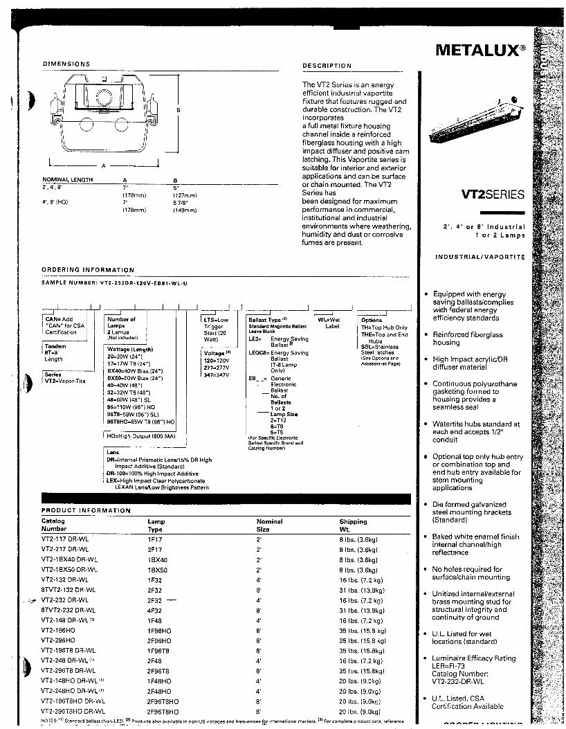
Lighting and camera mounting brackets, attachment method, and attachment hardware shall be designed and provided by the RCS Supplier. Information required for the design of brackets is shown in Appendix E and on the drawings. Lighting fixtures are not required to be supplied by the RCS Supplier. Approximate locations of Life Safety equipment is also shown on the drawing in Appendix E. RCS Supplier shall ensure that framing members, as needed for attachment of this equipment, are provided in appropriate locations.
5.9 Special Inspection and Test Plan
As required by the IBC, the design of the seismic restraint system and its members or elements shall include a special inspection and test plan prepared by a registered design professional. The plan shall identify the following: 1) the designated systems or elements that are subject to the plan, 2) the special inspection and testing to be provided, including the applicable reference standards and codes, 3) the type and frequency of testing required, 4) type and frequency of special inspections required, 5 ) the structural observations to be performed during erection or assembly.
The design of the pressure resisting system and its members or elements (including, but not limited to, rivets, panels, doors and windows) shall also include a special inspection and test plan prepared by a registered design professional. The plan shall identify the same items as listed above, as applicable.

EXCAVATOR METHOD PROJECT
Retrieval Confinement Structure
Specification Revision: 0 Page: 12 of 17
As a minimum, inspection and test plans shall include inspections as required by the IBC and by AWS D1.l
6. MANUFACTURING AND ASSEMBLY
6.1 General
All materials used in the structure shall be new, without defects, and free of repairs. Quantities of materials to be provided for erection and assembly shall be sufficient considering an appropriate waste factor. Modular panels shall be pre-assembled to the maximum extent possible prior to delivery on-site. BBWI will notify Supplier no less than one month prior to start of the second installation phase described in Section 1.2.3. Joint and penetration sealing materials (including silicone and joint sealing tape) shall be shipped to the project site two weeks prior to the second installation phase.
6.2 Materials
6.2.1 Stainless Steel Panels Including Sheet and Strip Material
ASTM A 167 or ASTM A 240, 300 series stainless steel, cold-rolled, annealed, and pickled with No. 2B finish on the outside surface. Inside surface is to receive a No. 4 finish. Stainless steel types 304L and 3 16L may be substituted for types 304 or 3 16. Thickness shall be 22 gauge, minimum.
6.2.2 Shapes and Bars for Frames and Structural Members
Shapes and bars shall be of ASTM A 36 structural quality carbon steel or ASTM A 992 steel shapes. Rolled steel plates, bars, and shapes shall be defined in ASTM A 6.
6.2.3 Personnel and Overburden Transfer Doors and Door Hardware
Doors for personnel access shall be pre-hung with the modular panel. Doors shall be one piece honeycomb construction fabricated from 20 gauge steel and 16 gauge cold rolled steel frame work (minimum). Doors to have viewing windows in accordance with Section 6.2.6. Doors to be finished as specified in section 6.3.2. Doors shall have integral thresholds unless otherwise specified herein or on the drawings. Provide simple pull and push plate egress hardware on all doors with the exception of doors leading to and from the RCS confinement itself (excludes the transfer vestibule overburden, personnel access, and personnel monitoring areas) which shall be provided with lock sets (lockable from exterior) as specified below. All door hardware shall conform to the requirements of NFPA 101.
Provide lock sets and cylinders compatible with Government-finished and installed Medeco High Security Locks "KeyMark" 7-pin interchangeable cores and Medeco High Security cams.

EXCAVATOR METHOD PROJECT
Retrieval Confinement Structure
Specification Revision: 0 Page: 13 of 17
6.2.4 Coiling Door
Painted carbon steel slats. Electric 120/208 volt, single phase or three phase. Do not supply 240 volt motor.
6.2.5 Windows and Portholes in Confinement Walls or Roof
LexanTM. MR-AC as manufactured by General Electric. Sizes and locations as indicated on the drawings.
6.2.6 Windows in Personnel Doors
LexanTM. MR-AC as manufactured by General Electric. Sizes and locations as indicated on the drawings
6.2.7 Joint Tape
Joint tape shall be flame-retardant polyethylene, 5 in wide minimum, gray in color with rubber based pressure sensitive adhesive. Adhesion to steel shall be 30 oz. per inch width, minimum.
6.2.8 Silicone Sealant
100% silicone sealant (white) for interior applications.
6.2.9 Sealing Gaskets
Gasketing material must be compatible with chlorinated solvents (such as flouroelastomer (Won) or flourosilicone sponge rubber (closed cell). Notably, chloroprene (Neoprene) and synthetic rubber are not acceptable for use unless the gasket will be completely isolated from potential exposure to chlorinated solvents which may be present due to excavation operations within the RCS proper.
6.2.10 Panel Attachment Rivets
Rivets shall be 3/16” Stavex Lo-Profile Head rivets, as manufactured by Avdel Cherry Textron Inc.
6.2.1 1 Bolts, Nuts, Studs, and Washers for Attachments and Accessories
ASTM A 307, commercial grade. Standard bolts shall be regular hexagon head type. Nuts shall be plain hexagon type.
6.2.12 High Strength Bolts, Nuts, and Washers for Structural Framing Members
ASTM A 325, Type 1, commercial grade, including heavy hexagon structural bolts, heavy hexagon nuts, and hardened washers. High strength bolts shall exhibit grade marks and

EXCAVATOR METHOD PROJECT
Retrieval Confinement Structure
Specification Revision: 0 Page: 14 of 17
and fasteners without headmarkings, or with headmarkings identified on the United States Department of Energy (DOE) Headmark List, are prohibited.
6.3 Fabrication
6.3.1 Welding
The Supplier shall establish and qualify Weld Procedure Specifications (WPS) for any off- site welding performed during this subcontract in accordance with the requirements of AWS B2.1, D1.1 or D1.6 as applicable. Off-site welding shall be performed by welders or operators qualified in accordance with AWS B2.1, D1.1 or D1.6 as applicable.
6.3.2 Painting
Carbon steel components shall be coated with the standard factory coating (Supplier's standard blue or green), to resist rusting and mild acidic or caustic washing. Fabricated structural steel elements, or any pre-finished components that have undergone welding or other processes that would compromise the original manufactures finish shall be finished as follows:
Exposed steel shall be prepared in accordance with Steel Structures Painting Council (SSPC) specification SP-3, Power Tool Cleaning to remove all loose rust, loose mill scale, or residual paint.
After surface preparation, the steel shall be washed with a liquid phosphate high-pressure spray system prior to application of the finish coating.
After washing, the steel shall be primed and finish painted with a single part urethane coating. Painting shall be done in accordance with the manufactures recommended application instruction.
6.3.3 Panels and Joints
Interior panel joints and seams must be able to be readily sealed subsequent to building assembly. Additionally, the application method of caulking and taping at joints must be such that a seal is not compromised upon application of a negative pressure of 4.0 inches, water column.
Each stainless steel sheet on a panel shall have the edges set back slightly from the edge of the steel frame. This will preclude the sheathing from exposing raised/sharp edges.
Each stainless steel sheet panel shall have a crossbuck crease. This crossbuck creasing feature will increase the rigidity of the sheet metal and reduce the possibility of an "oil canning" effect.

EXCAVATOR METHOD PROJECT
Retrieval Confinement Structure
Specification Revision: 0 Page: 15 of 17
6.3.4 Fabrication Process Control
Shop travelers or other work controlling documents, drawings, and specifications will be controlled to ensure only approved documents are used during material procurement and fabrication of the RCS. The controls placed on the work document shall include specific identification of each document, date of release, and approval signature(s).
6.3.5 Material Traceability
The Supplier’s material controls shall include identification to parts of the assembly, and traceability of materials to Certificates of Conformance.
7. QUALITY ASSURANCE
7.1 General
The RCS shall be designed, fabricated, erected, and tested per the requirements of this specification.
7.2 Nondestructive Examinations
The Supplier shall conform to the approved special inspection and test plan as outlined in Section 5.9, Special Inspection and Test Plan. As a minimum, nondestructive examination by the Supplier will consist of visual inspection of all “structural welds” as identified on the approved shop drawings. Visual inspection procedure and acceptance criteria shall conform to requirements of AWS D1.1.
7.3 Procurement Document Control
Supplier’s procurement documents shall identify appropriate test, inspection, and acceptance criteria for determining acceptability of the item or service. Copies of all procurement documents and material certifications shall be made available for review by BBWI the representative.
7.4 Document Control
The Supplier shall control all changes made to shop travelers, drawings, inspection or welding procedures or other desigdfabrication documents using revision controls.
7.5 Measuring and Test Equipment
The fabricator and inspection subcontractors must ensure that any measuring and test equipment (calipers, torque wrenches, flow meter, etc.) are calibrated if used to verify critical characteristics of the design or fabrication. For example, torque wrenches to torque high-

EXCAVATOR METHOD PROJECT
Retrieval Confinement Structure
Specification Revision: 0 Page: 16 of 17
strength fasteners must be calibrated. Calibration records shall be available for inspection by the BBWI representative.
7.6 Inspection Status
The fabricator must maintain status of items awaiting inspection or testing. The statusing process will ensure that items that are awaiting inspection or testing are clearly identified on the items or in documents traceable to the item (for example: travelers). The inspection subcontractor must authorize removal of the status tags, if used.
7.7 Nonconforming Items/ Corrective Actions
Items that do not conform to specified design requirements shall be controlled to prevent inadvertent installation or use. Those items shall be identified and segregated in a designated hold area until dispositioned or disposed. Non-conformances will be documented and approved by the engineer-of-record and submitted to BBWI on Supplier Interface Document (Form 540.16).
The Supplier shall determine and document the cause of and the corrective action for the nonconformance(s). BBWI shall be notified of corrective actions taken to prevent recurrence.
7.8 Quality Assurance Records
The Supplier must protect all design, fabrication, testing, and material documentation from loss, deterioration, or damage prior to submittal to BBWI per the Vendor Data Schedule.
8. PACKAGING AND SHIPPING
8.1 Piece Marking and Identification
All individual parts or bundles of packages of identical parts are to be clearly marked for identification or otherwise identified by clear installation procedures. Bolts and fasteners shall be packaged according to type, size, and length. Loose nuts and washers shall be packaged according to size and type. The shipping documents shall include a shipping list showing the description, quantity, and piece mark of the various parts, components, and elements.
8.2 Packaging
Parts shall be packaged to protect from damage during transportation to the job site and during erection.
8.3 Material Delivery
The building system materials shall be delivered to the project site between the hours of 7 a.m. to 4 p.m Monday through Thursday. Unloading will be accomplished by a construction
412.09 (11/05/2001 -Rev. 06)
Identifier: SPC-358 Revision: 0 Page: 17 of 17
Performance Specification
OU 7-10 GLOVEBOX EXCAVATOR METHOD
PROJECT Retrieval Confinement Structure
I
contractor with union labor. Supplier shall include documentation that describes the recommended method of off-loading with all items in each shipment. Supplier shall also include any special off-loading devices (e.g. special slings) as recommended.
8.4 Handling
At no time shall materials be dropped, thrown, or dragged over the transport equipment or the ground. Materials shall be protected at all times from standing water. Supplier shall include instructions for proper storage.

Appendix A
Vendor Data Schedule

Vendor Data Schedule
A. As-Built Drawings B. Assembly K. Manufacturers Data Drawings Report AE. MSDS C. Attendance L. 0 8 M Manual u. Shop Drawings AF. Hardware Schedule Record M. Parts List ~ , ~ e ~ ~ ~ ~ z , C , O : ~ AG. Specification D. Blasting Plan N. Piping Drawing AH. E. Catalog Data 0.
Procedurellnstructions F. Chem & p. Pump Head Physical
Analysis Q. Personnel AJ. Recommended Spares
AB. G. Concrete Mix Qualifications Design R. Red-line Drawings H. Control S. RSMl 8 Maintenance ~ ~ ~ ~ ~ $ ' ~ ~ : ~ ~ ~ e AM. Certificate of Disposal or System Diagram Log
AD. Wiring Diagrams verification I. Design T. Sample(Color, Texture, Calculations etc.) J. Installation Instructions
t: ~ ~ ~ ~ ~ ~ ~ ~ ~ e S ;cfacturing/lnspectionmest
Testing
AA. UUFM Listing
AI. Test Certification
AK. Special ~ 0 0 1 s List AL. Certificate of Conformance
z. Test Reports
Page 1 of 2
AO. Design Qualification Testing AP. Traceability Procedurt AQ. Cleaning Procedure AR. Weld Procedure Qualificaiton AS. Welder Performance Personnel Qualifications AT. Non-Destructive
Certifications AU. Inspector Certifications AV. Limited Shelf Life,Operational Data AW. Special Packaging, Shipping, and Rigging Procedure AX. Certificate of Material: to ASPAE Code AY. Chemical Inventory AZ. Other
Personnel
431 . I4 08/0 1 /ZOO1 Rev. 03
Vendor Data Schedule
OU 7-10 GLOVEBOX EXCAVATOR METHOD PROJECT RETRIEVAL Proj ect Title co N F IN EM E NT STRUCTURE
Purchase Order/ Work Order/ 021052
Subcontract No.
Rev: 1
http://thomar2.inel. gov/pls/vds/vdcs~reports.vdcs~schedule?swp~identi fier=2 1 003 4/4/2002

Vendor Data Schedule c- Page 2 of 2
AS Welder Performance
AT Non-Destructive Examination Personnel Certifications
Certification of
Instructions: 1. Refer to subcontract documents for instructions on submittals. 2. Electronic submittals in lieu of paper documents are acceptable and encouraged. 3. The normal number of copies required is ONE. If more are required, the number will be shown here. 4. THE INEEL WILL SCAN ALL SUBMITTED VENDOR DATA INTO A SYSTEM THAT IS ACCESSIBLE TO ALL INEEL EMPLOYEES UNLESS THE SUPPLIER/SUBCONTRACTOR IDENTIFIES SUBMITTED INFORMATION AS PROPRIETARY.
http ://thomar2 .inel.gov/pls/vds/vdcs~reports.vdcs~schedule?swp~identi~er=2 1 003 4/4/2 002

Appendix B
Drawings

l- W W
v, r
9 t- i=
n
a
2 < < I
rr Q
E # 5 5
il 0 0
a
1;

Ih I
n Z w (3 W -I
(3 Z Z w a. 0 K 0 0 0
-
-
c)
N
CI
7 4
uuwm v, W I- O
3dAl
-0-.s L .o-.SI
* 0 I
2 - v
0 I z
0
tn I c
A
- , - - .9-,2 1 3 .OL-.9Z
I c .O-,B .o-.92 .O-.Lt


n
cn W t- 0 Z
+ 0
K 0
W
c
ri n
.O-,tZ

4
"1 .O-,tZ
.t/c t-,L1
4
.E
d \
yl
n
I t '. ri I '.r
C.
* W I -.
.t/l E-.L
.6-,61
.O-.tZ
E l 0
I ,
W 8 . I
0
N '2.
I- o I
I .t/l E-.L .L-.9
-0-.tz
T t- I
l-4 0 I i.,
a
3 n
I '+
tn I In
N > N 1
N c
-
u I . n
I n Lr W W VI 3 .Z/l 2-.6
W w v) I
o I + : n
I -+ I E l t- 1 1 -
. t / L E-.L .L-3
.6-.OZ

I 0 1 m I 0
L W 0 e
0 > z> o m L
0 I 2
I - .o-,z L
.o-,z L -
c-
I
2 I
- 0 1 -P-, 1 1
. 0 I
m c
.o-.L 1
% 02 O W t w -In
P 0 Z A c
I .Q-.OL
.0-.11 -
-7 I 0 I
2
--
I 0
I ‘N
.o-.Zl -0-.ZL
- J
.O-.tZ -
.o 1-.E L .z-.z I 0
I
c
0 -
1 I
.o-.ZL
* 0 I in c
c + L- -0-.z 1 t 1 .o-. 1 I .O-S 4
.O-.PZ
a I Is I
4 w
w 0 cc 0
3du
W
< a
P 0 !A
.e-.z
* ,r
k , In I
I
0 I
PI
/I . 0
I PI
a
.Z-,SZ
Q
"- 3' F ?
-t W
f a v) 0 LL
.t/P 01-.t
.+/l 01-.+ r+----- . . . . . . . . . . . . . . . . . . . . . . I.
* t > I
* t
I r- -I W
f :: a
LL
I 3 v) In
Appendix C
Penetrations, Attachments, and Interfaces for RCS
and Related Structures

r
e V Y 0 a a n 0 r I- Lu I IL
4 > 0 X u1
X
e a
2 9 W >
VI z r. 3 0
N 0 0
N 2 -J
VI C - 3 c7
E a,
E
B 0 Z
._
m 0
- .-
c
VI C - E c
c .- 3
- m 0 a, a
0 z
._
D
K Q a VI
- 1 NI P
Y= % % % % m % % n
$ 4 4 5 4 4 4 4
4 4 4 5 4 4 4 4 h h h h h h i .
X X X X X X X
b b h h ' m h 'm
n s C
N
0
L C
c: r
$ a, w

N
+ 0 ili
n r
2 a 0 + w z K
4: > 4: ti X U X
F
iil >
(3
r-L 3 0
Ei
N 0 0
N s
I-
I
I
c
z 0 5 $ z W n 1 w
I! Y I- z W 0
m m
m s
L . . 2 9 c h -I

m
z % 0 U Q 0 0 I- W I K
4: > 4 0 X w X
W >
u ' E
r-: 3 0
r
e
s
N 0 0
N r? d
>
!as( E m K
W li 8
I- v)
> v)
f r
r
o m
= o
P N '! 'I r
P F
0
f E E E
n ._ U $ 0 0 0 c:
0
> > -* 0 U 0 U

z I- u w 0 a~ Liz z w n Ij u
P I- v)
> fn
n o - 2
* -
, o l - 3
1a- 3
VI 0 a-
9
E
a - c " U
c L c
c
r . - c 0 E
a
- E
5 W
m W n
5 L
._ :i E : E ? - a E = S ? E C m v -
v: c: a- -
- m K ._
&
x &
P N
m X
N I "I
v)
a- 8
1
U c

I- o W
K
D 0 I b- W I a:
z a
F a > a 0 X w X
W >
u s 0 h 3 0
N 0 0 N . s
I

Appendix D
Fire Protection Piping Layout Drawings
(For Information Only)

c3 Z 3 a QL n LL W QL I
X
-10
f f c-
v)
V K
.Z/L 6-.9 >
>
3 I N
2 '2.
I
6 I .
q 7 N
3 I

0 m + j n I
r)
m- a 0
i\
I I .9-.6L
F 0 W I- O nf CL

Appendix E
Proposed Lighting Fixture Vendor Cut Sheets
and Layout Drawing

LUMARK" DESCRIPTION
The Lumark Nighthawk 111 utilizes a soft-cornered aerodynamic design to provide excellent €PA ratings and an aesthetically pleasing appearance. Dark bronze polyester powder coat finish assures corrosion resistance and long-lasting aesthetics. U.L. 1572 listed and labeled for wet locations. CSA certified.
APPLICATION
The Nighthawk 111 uses an innovative die-cut optical design which delivers maxlmum beam control for storage areas, rail yards. loading docks and building perimeters.
SPECIFICATION FEATURES
A. -La t c h e s
Formed aluminum flush draw-action latches offer easy access to lamp compartment without tools and maintain integrity o f seal when closed.
B - H o u s i n g
Aerodynamically designed die-cast aluminum housing has low EPA rating.
C-Door
Diecast aluminum with integral cast hinges for removal without tools.
D-Lens Heat- and impact-resistant tempered glass. Lens is mounted flush with door surface to reduce wind drag and prevent dirt or moisture from accumulating.
E -R n I i e c t or
Computer designed die-cut reflector system delivers superior beam control and efficiency. F .-G a s k e t
Door gasket is foam-in-place silicone, providing maximum protection of interior components from the elements.
G - . B a l I a e t
Ballast components are hard mounted to fixture housing for maximum heat dissipation and extended component and lamp life.
H -Mounting Diecast aluminum integral slipfitter mounts on nominal 2 3jE' or 3' O.D. tenons. A degree-marked quadrant is cast in for easy and accurate aiming.
21 I 69
*--T 1 lol
r iml
D I M E N S I O N S
1 ~ O o W Hos c MH. lm Hps 9 in' 124lmml
lwoW MH i o in- 1267rnrnl
lOOOW L A M P PLACEMENT
w COOPER L I G H T I N G
NKNIGHTHAWK Ill
1 5 0 - 1 o o o w H l g h P r e s s u r e Sodium
M e t a l H a l l d m - SLIPFITTER FLOODLIGHT
ENERGY DATA
15OW M H HPF I190 Wend
RNCIU Wnl I y l Watt. 1SOWMHHPF (185Watts)
CHll Ballast hpn Warn 250W HPS HPF 1300 Wand
Hid..- Ed..( *pa watts
CWA WlUt hpr( WJte 175W M H HPF (210 Wn8l ZWW HPS HPF 1250 Wand ZWW MP HPF (232 Warn1 250W M H HPF (295 Wand 3MW MP HPF 1365 Warn1 350W MP HPF 1395 Waml MOW MH HPF 1455 Wan.) UXlW HPS HPF (465 Wan81 44OW MPHPF 1448 Waml 6OOW HPS HPF 1665 Wanal 750W HPS HPF (E35 Wand 750W MP HPF 1835 Warn) looOW M H HPF 11080 Wand looOW HPS HPF I11W Wan4

N X N I G H T H A W K 111
optia (add ar suffix) PER-NEMATwktlock ROtOmnlml
Recaptacle n-single FWE (im, 277 O( 347w FZ-Double Fussd 1208.244 or UMVl o.amm ~ e ~ ~ r i k e oc ~ r y o ~ t Base
W u a m Remike Cdd Stan lime IHai mike only)
Delay Relay (not available in loooWl MR-Pulta T-Removable Quick-Oinconnecf Powar Tray
Stan MH IcanrWI be used with 1 W unilsl l o o ( L 1 W
P H O T O M E T R I C S
F o o t c a n d l e T a b l e F l o o d l i g h t S u m m a r y
Sdecr mounting bigin and read across for footcandle values of each isofoatcandle line. Distance in unite of
Maximum Candlepower Maximum Candlewwer Venical Angle
25981 CO 0 h r e a
AaMI*l lorder separately) NNK-Top or Banam Visor SWINK-Single Side Visor SV/NK-Oo&a Side Visor WG/NK.!Mre Guard OAlOll-Shorling Cap for NEMA TWiSnock Photomntml
Receptacle OAlOlhPholoalectric Conlrol. 1OS-2Bs-vOll NEMA Typa OAlOt7-Photosleclric Control. 480 Van NEMAType OA102&Field lnslalled NEMA TwMock PhotomnIrol
Receptacle lorder photomntrol wparatelyl OA12m-Phatoelectric Control, 347 Van NEMAType VWNK-Vandal Shield U-Lamp Included
Maximum Candlepower Horir Angle 0 Degrees rnauntina heiaht. - ;;dy-Jd:bzh Bsam Flux-10% of Max. 34125 Lumens A B C D E Baam EfficiencyllOX of Max. 683 Perwnt 10.00 5.00 2.w 1.00 0.50 T*al Flux 35230 Lumens 20'
2 5 6.44 3.M 128 0.64 0.32 Efficien'=V 70.5 Permnt
30' 4 . u 222 0.89 0.u 0 1 2 35' 3.27 1.Q 0.65 0 3 3 0.16 10' 2.50 1.25 0.50 015 0.13
5 4 3 2 1 0 1 1 3 4 5 HPNK--76-400 4CC-Watl HPS
F o o t c a n d l e T a b l e F l o o d l i g h t S u m m a r y %led mounling heighl and read across for tootcandle values of each isofoatcandle line. Distance in units of
Maximum Candlepower m21a a, Maximum Candl-er Venical Anole -5' Deareer
5 4 3 2 1 0 1 2 3 4 5 MHNK.-76-400 4CC-WalI MH 36,OOO-Lunen Clear bmp
0 R O E RING I N F O R M A T l O N
mounting heiqht. %" ;dyz:bzb A E C O E
2(r 10.00 5.00 2.00 1.00 0.50 25' 6,AO 3.20 128 0.64 032 w 4 . u 2.22 0 89 0.u 022 35' 3.27 1.63 0.65 033 0.16 44' 2.50 1.25 0.50 025 0.13
Mau'mum Candlepower Horir Angle 0 Degrees Bsam Flux-10% of Max. 2553A Luwmna Beem Efficiency-1096 of Max. 72.9 Pement Total Flux 2623 Lumens Total Efiicienw 72.9 Pnrmni
EPA R a t i n q s : S l l p f i t t e r M o u n t l n q Fimn wnd Mal Isq. *.) Am* Front Side 4Sfram Horizontal 2.7 1.2 90' fram Horizontal A 2 1.2 (r from Horizontal 1.1 1.2
# COOPER Lighting
NOTE. S-lftcal&ru and dimandow sub@ Io chs- wllhoul mlm.
Viait our web site at www.cooperlighting.com ADH881213 Customer First Center 1121 Highway 74 South Peachtree Clty, GA 30269 710.486.4800 FAX 770.486.4801

a BRACKETS Brackets for R o o f t o p or W a l l M o u n t i n g
P A R A P E T B R A C K E T S T E E L A N G L E B R A C K E T R I G H T A N G L E B R A C K E T
Catalog Tenon Fixture Number Size (In.) Configuration FA63 3 0.0. Single Parapet Mount
COOPER LIGHTING
Catalog Number SAB NOTES: Standard finish is hot dip galvanize. Mounting hardware not included.
Cataloa Tenon Size (In.) Number '
RAB 2 38 0.0. RABV RABX
2 3BO.D. 2 318 OD.
Bracket Length (In.) 8 14 8
RABX14' 2 380.0. 14 NOTES: 'Standard finish IS primed Add suffix *G- for hot dtp galvanize. Mounting hardware not included. 'Steel pole mounting
NOTE: Speclficalianr and dimensions wb]m 10 change wlhoul nolue.
37
- D I M E N S I O N S D E S C R I P T I O N
The VT2 Series is an energy efficient industrial vaportite fixture that features rugged and durable construction. The VT2 incorporates a full metal fixture housing channel inside a reinforced fiberglass housing with a high impact diffuser and positive cam latching. This Vaportite series is suitable for interior and exterior
NOMINAL LENGTH A 6 applications and can be surface or chain mounted. The VT2 2'. 4'. 8' 7" 5
t - - - A - - - - - - I
4', 8' (HO) 1178mm) 1127mm) 7" 5 718" (178mm) 1149mml
Series has been designed for maximum performance in commercial, institutional and industrial environments where weathering, humidity and dust or corrosive fumes are present.
0 RD ER I N G IN FOR M A T 1 0 N
S A M P L E N U M B E R : VT2-132DR- lZOV-E881-WL-U
F = A d d 'CAN' for CSA ~ 1 p:Tof 1 Certification 2 Lamps
(Not mcluded)
I Length
VTZ=Vapor-Tite
Wattage (Length) 20=20W (24") 17=17W T8 (24") BX40=40W Biax (24") BX50=50W Biax (24") 40=40W (48") 32=32W T8 (48") 48=60W (48") SL 9 k l l O W (96") HO 96T8=59W (96") SL) 96TBHO=85W T8 (96") HO
HO=High Output 1800 MA)
Trigger Start (20 Wan1
120=12ov 277=277V 347=347v
Lens DR=lnternai Prismatic Lens/l5% DR High
DR-100=100% High Impact Additive LEX=High impact Clear Polycarbonate
Impact Additive (Standard)
LEXAN LenslLow Brightness Pattern
~~ ~ ~
I i
Ballast Type (*I
THE=Top and End LE% Energy Saving
LEOCB= Energy Saving Steel latches Ballast@ SSL=Stainless
Ballast (See Options and IT-8 Lamp Accnssoriffi Page)
Only) EB = Generic
No. of
Lamp Size 2=T12 8=T8 5=T5
(For Specific Electronic Ballast Specify Brand and Ca1alc-a Number)
P R O D U C T I N F O R M A T I O N
Catalog Lamp N o m i n a l Shipping
VT2-117 DR-WL 1F17 2' 8 Ibs. (3.6kg) Vr2-217 DR-WL 2F17 2' 8 Ibs. (3.6kg) Vr2-1BX40 DR-WL 1 EX40 2' 8 Ibs. (3.6kg) Vr2-1 EX50 DR-WL 16x50 2' 8 Ibs. (3.6kg)
Number Type Size wt.
Vr2-132 DR-WL 1 F32 8M2-132 DR-WL 2F32
. 3 Vr2-232 DR-WL 2F32 - 8TVT2-232 DR-WL 4F32 VT2-148 DR-WLI'l VT2-196HO VT2-296HO
1 F48 1 F96HO 2F96HO
4' 8' 4' 8' 4
8' 8'
16 Ibs. (7.2 kg) 31 Ibs. (13.9kg) 16 Ibs. (7.2 kg) 31 Ibs. (13.9kg) 16 Ibs. (7.2 kg) 35 Ibs. (15.8 kg) 35 Ibs. (15.8 kg)
Vr2-196T8 DR-WL 1 F96T8 8' 35 Ibs. (15.8kg) VT2-248 DR-WLI'I 2F48 4' 16 Ibs. (7.2 kg) Vr2-296T8 DR-WL 2F96T8 8' 35 Ibs. (15.8kg) VT2-148HO DR-WLi'l 1F48HO 4 20 Ibs. (9.0kg) VT2-248HO DR-WLi'l 2F48HO 4' 20 Ibs. (9.0kg) Vr2-196T8HO DR-WL 2F96T8HO 8' 20 Ibs. (9.0kg) VT2-296T8HO DR-WL 2F96T8HO 8' 20 Ibs. (9.0kg) NOTES "' Standard ballast (Non-LE3; Products also availabie in non.US voltages and frequencies !:: international markets. For complete product data. reference .. . ., - - . . .
METALUX@
VT2S E R I ES
2'. 4 ' or 8 ' I n d u s t r i a l 1 or 2 L a m p s
I N D U S T R I A L / V A P O R T I T E
Equipped with energy saving ballastdcomplies with federal energy efficiency standards
Reinforced fiberglass housing
High Impact acrylidDR diffuser material
Continuous polyurethane gasketing formed to housing provides a seamless seal
Watertite hubs standard at each end accepts 1/2" conduit
Optional top only hub entry or combination top and end hub entry available for stem mounting applications
Die formed galvanized steel mounting brackets (Standard)
Baked white enamel finish internal channeVhigh reflectance
No holes required for surfacekhain mounting
* Unitized internallexternal brass mounting stud for structural integrity and continuity of ground
* U.L. Listed for wet locations (standard)
* Luminaire Efficacy Rating LER=FI-73
VT2-232-DR-WL Catalog Number:
U.L. Listed, CSA Certification Available
c
I
0 __
0 0 w In

Appendix F
Retrieval Confinement Structure Analysis and Loading Criteria
This appendix is for information only. It is not to be considered as part of the specification requirements. If a conflict exists between
this Appendix and the body of this specification, the specification will control.

ENGINEERING DESIGN FILE
3. Site Area and Building No.: WMF-671
EDF- 2053 Rev. No. 0
Page 1 of 4
WMF-671 4. SSC IdentificationlEquipment Tag No.: RCS
i RIA >eTformer A
Zhecker R
ndependent A Deer Reviewer
It also gives preliminary estimates of the RCS weight and seismic base shear.
3. Review (R) and Approval (A) and Acceptance (Ac) Signatures:
Typed NameIOrganization Signa tu re Date 3/25/02
3/25/02
Scott A. Jensen P.E.
Ste+nie Austad P.E.
Patrick Bragassa P.E. 3/25/02
Ypprover I I J/ I
A S.A. Davies / Project Engineering
I
7. Distribution: (Name and Mail Stop)
I I
Hard copy distribution to: S.A. Davies (MS 3650), M.B. Pratt (MS 3950), OU 7-10 Glovebox Excavator Method Records Management (MS 3920), Scott Jensen, David Stephens. Electronic copy distribution to: B.R. Helm (MS 3765, [email protected]), OU 7-1 0 Glovebox Excavator Method Records Management (MS 3920, [email protected]), Scott Jensen.

ENGINEERING DESIGN FILE EDF- 2053 Rev. No. 0
Page 2 of 4
Purpose
This EDF documents the structural design and loading requirements for the Retrieval Confinement Structure (RCS) for the OU 7-10 Glovebox Excavator Method Project.
Scope
This EDF is provides information necessary for the structural analysis and design of the RCS.
Background
The Glovebox Excavator Method Project objective is to demonstrate the safe retrieval of TRU waste from a specific and preselected area (OU 7-10) of Pit 9 in the Subsurface Disposal Area (SDA) at the Radioactive Waste Management Complex (RWMC, part of the INEEL’s Waste Area Group (WAG) 7 .
The RCS is the confinement structure enclosing the excavation area for this demonstration project.
Safety Category
The RCS is safety significant. It is Performance Category 2 (PC-2) regarding earthquake loading. It is protected from the effects of wind, snow, rain and flood by other structures.
Assumptions
A structural steel framework supports the RCS. A weather enclosure and other features at the RWMC protect the RCS from the effects of wind, snow, rain and flood.
Acceptance Criteria
The provisions of the International Building Code (IBC) 2000 shall govern the structural design and analysis of the RCS unless otherwise noted herein. The following chapters are particularly applicable to the RCS design:
Chapter 16 Structural Design Chapter 17 Structural Tests and Special Inspections Chapter 22 Steel Chapter 24 Glass and Glazing Chapter 26 Plastic
Analysis and Design Requirements and Criteria
General. The RCS may be designed and constructed in accordance with any of the design methods and conventional construction methods permitted by the IBC.
Strength. Refer to IBC 1604.2 for requirements.
Serviceability. Refer to IBC 1604.3 for requirements. The drift limits applicable to earthquake loading may be exceeded if adequately justified.
The RCS interfaces with three glovebox structures and an excavator. Flexible connections shall be provided at the interfaces to limit the load transfer between the RCS and these components. The RCS deflections at the connection points shall be limited to a maximum of 3/8 of an inch in any direction.
Analysis. Refer to IBC 1604.4.

ENGINEERING DESIGN FILE EDF- 2053 Rev. No. 0
Page 3 of 4
Importance Factors. The seismic load importance factor for the RCS shall be 1.5. The snow load and wind load importance factors are not applicable to the RCS design.
Load Combinations. Refer to IBC 1605. Normal operating pressure acting on the RCS shall be considered a live load and shall be included in appropriate load combinations. The normal operating pressure need not be included in load combinations that also include construction or erection live loads. It needs to be included with operational or maintenance live loads.
An additional load combination that includes dead loads and the maximum design pressure on the RCS shall also be used in the design and analysis.
Dead Loads. Refer to IBC 1606. The RCS roof dead load includes selfweight (framing and steel panels, guardrails, etc.), the weight of a camera, the lighting system, and a fire sprinkler system. The minimum assumed dead load from the camera, lights and sprinkler system for the RCS roof shall be the greater of the loads as shown on the drawings or 6 pounds per square foot (psf).
Live Loads. During normal operation the only live load imposed on the RCS is the negative pressure (inward pressure) imposed by the ventilation system. The design value for the normal negative pressure shall be 1 inch of water (5.2 psQ
The live load on the RCS roof shall include a concentrated load of at least 250 Ibs. This load is provided to accommodate maintenance of the lights and camera located on the roof. The load may occur at any single location on the RCS roof.
Live loads on the RCS roof shall also include any loading on guardrails or other fall restraint features provided for the RCS erection or maintenance of the lighting and camera.
Live loads shall include loads imposed by normal construction or erection procedures.
Maximum Design Pressure. The maximum negative pressure on the RCS shall be 4 inches of water (20.8 psf).
Snow Loads and Wind Loads. Snow and wind loading are not applicable to the RCS.
The weather enclosure will protect the RCS fiom snow and wind loading during operations. Snow or wind loading of the RCS may occur during erection. However, temporary bracing can accommodate these loads. The snow or wind loading, during construction activities on individual components, can be assumed to be less than the maximum design pressure (20.8 psf) for those components.
Soil Lateral Load, Rain Loads and Flood Loads. Soil lateral load, rain loads and flood loads are not applicable to the RCS.
Earthquake Loads. Refer to JBC 1613 through 1622. The following criteria shall be used for the RCS.
Short period acceleration, Ss - 0.357 g's I -sec acceleration, S 1- 0.13 1 g's Site Class - C Seismic Importance Factor:
Ie - 1.5 for structures Ip -1.5 for components
Seismic Use Group - 111.

ENGINEERING DESIGN FILE EDF- 2053 Rev. No. 0
Page 4 of 4
References
International Building Code 2000 DOE-STD-I 020-2002 January 2002, Natural Phenomena Hazards Design and Evaluation Criteria for Department of Energy Facilities
Calculations
See the attached calculations for an estimate of the RCS weight and calculations for earthquake loading for the main framework and components.
Conclusions
The preliminary calculation for the weight of the RCS is 39,500 pounds.
The preliminary calculation for the total base shear from earthquake loading of the RCS is 4,230 pounds.
The horizontal design force used for design of anchorage of components mounted on the roof of the RCS shall be at least 0.41 g’s (0.41 times the component weight).
Attach men t s Loading Calculations - 6 pages

Scott A. Jensen P.E. RCS Weight & Earthquake Loading Calculations
Calculation Sheet Page 1 of 6
3/28/2002
Purpose
The purpose of these calculations is to determine a preliminary estimate of the weight and earthquake loading of the RCS.
Scope
These calculations are limited to the previously stated purpose.
AssumptionslCriteria Refer to RCS preliminary drawings for information on the RCS configuration.
RCS dimensions: L := 52.ft B := 27-ft H:= 24.ft B1 := 1 5 f t B2:= 12.ft
52'-0"
L1:= JT? L1 = 21.21 ft L2 := L - 2.B1 L2 = 22.00ft
Steel unit weight: ys := 490.pcf
Earthquake load criteria: ss:= 0.357 S1 := 0.131 Ip:= 1.5 Ie := 1.5
Site Class C Seismic Use Group - Ill
Acceptance Criteria Not applicable to these calculations.

Scott A. Jensen P.E. RCS Weight & Earthquake Loading Calculations
Calculation Sheet
312a12002 Page 2 of 6
Weight Calculations
2 Aceil = I 179 ft 2 Calculate ceiling/roof area Aceil := L.B - BI
Calculate wall areas A1 := L.H
A2 := B2.H
A1 = 1248ft2
A2 = 288 ft 2
A3 := A2
A4 := L1.H
AS := A4
A6 := L2.H
2 A4 = 509ft
2 A6 = 528 ft
2 Awall := A1 + A2 + A3 + A4 + AS + A6 Awall = 3370ft
Estimate the RCS Wall Panel Framing
Panel width Bp := 4.ft Unit weight of water y~ := 62.4.pcf
Load ww := 4.in.yw.B~ ww = 83.20plf
Assume allowable stress Fb := .6.36.ksi Fb = 2 1.60 ksi
Mmax 3 s x 3 2 WW.H
Mmax := - Mmax = 71.88kip.in Sx := - Sx = 3.33 in - = 1.66 in
5 . w . H 4
8 Fb 2 4 H
120 384.A.E A = 2.40 in E := 29000.ksi Ix := Ix = 8.92in A := -
4 Try C4x7.25 Sx := 2.29.in ~x := 4.59.in
Ix 4 - = 4.46 in 2
Mmax fb := - 2.sx
fb = 15.70ks.i 4 5.ww.H
Amax := Amax = 2.33 in 384.E.2.I~
4 Ix := 7.49.in 3 Try C5x6.7 Sx := 3.in
Mmax 2.sx
fb := - f b = 11.98ksi
Estimate the RCS Roof Panel Framing
4 5.ww.H
Amax := 3 84.E. 2 . IX
Amax = 1.43 in
Roof panel span Lr := 27.ft w := ww + 2 . p s f . B ~ w = 9 1.20plf

Scott A. Jensen P.E.
2 Mmax := -
w. Lr 8
RCS Weight & Earthquake Loading Calculations
Mmax sx := -
Fb 3 Sx = 4.62in
Calculation Sheet
3~2a12002 Page 3 of 6
sx 3 - = 2.31 in 2
4 Lr 5 . w. Lr 4 A := - A = 2.70in E := 29000.ksi Ix := - 120 384.A.E
Ix = 13.93in
Mmax = 99.73 kip.in Try C5x6.7
Mmax fb := -
2 , s x fb = 10.80ksi
Ix 4 - = 6.96in 2
4
3 84. E. 2. IX 5 . w w . h
Amax := Amax = 1.23 in
Lr 240
= 1.35 in -
Estimate weight per square foot of RCS panels
2 Assumed panel area Ap := 4.ft.H Ap = 96.00 ft
Thickness of panel sheet ts := 0.0598.in Assumes 16 gage ws := ts.ys or lighter
ws = 2.44 psf
Length of angle framing per panel Lap1 := 6-4.ft
Lap2 := 2.H + 2-4.ft
Lap1 = 24.0ft
Lap2 = 56.0ft
Framing weight per foot wapl := 3 . 0 7 . ~ ~ Assumes 3x2x3/16 angles
wap2 := 6.7.plf Assmes C5x6.7
Wa := wapl.Lap1 + wap2.Lap2 Wa = 448.881bf
Total weight of panel Wpanel := Wa + Ap.ws Wpanel = 683.30 lbf
Weight per square foot of panels Wpanel
wpa:= - AQ
Estimate weight of lights and fire sprinkler system
wpa = 7.12psf
22.60.lbf Lights = 1.12psf
Aced
Assume 4 psf for the sprinkler system wco := 6.psf
Ceiling weight Wceil := Aceil-(wpa + wco) Wceil = 15.47 kip
Wall weight Wwall := Awall.wpa Wwall = 23.99 kip
Wwl := Al-wpa Ww2 := A2.wpa Ww3 := A3.wpa Ww4 := A4-wpa
Ww5 := AS-wpa Ww6 := A6.wpa
Wwl + Ww2 + Ww3 + Ww4 + Ww5 + Ww6 = 23.99kip

Scott A. Jensen P.E. RCS Weight & Earthquake Loading Calculations
Calculation Sheet Page 4 of 6
3128l2002
RCS Structure Earthquake Loading Calculations
SS = 0.36 S1 = 0.13 Fa:= 1.2 See IBC Table 1615.1.2(1)
FV := 1.67 See IBC Table 1615.1.2(2)
Equation 16-1 6 Sms:= Fa-Ss
Equation 16-17 Sml := Fv.S1
Equation 16-1 8 Sds := -.Sms
Equation 16-1 9
2 3 2 3
Sdl := -.Sml
Sms = 0.43
Sml = 0.22
Equates to Seismic Design Category D See Table 1616.3
Sds = 0.29
Sdl = 0.15 3 -
Ct := 0.020 Equation 16-39
R := 4 See Table 1617.6
CSI := - Sds Equation 16-35
Csl = 0.1 1
Bearing Wall System - Ordinary steel braced frames
Csmin := 0.044.Sds.Ie Equation 16-37
Csmin = 0.02
Cs := if(Csl < Csmin,Csmin,if(Csl > Csmax,Csmax,Csl)) cs = 0.1 1
Seismic Base Shear (Equation16-34) V := Cs-(Wwall + Wceil) V = 4.23 kip
Vceil := Cs.Wceil Vwl := Cs.Wwl Vw2 := Cs-Ww2 Vw3 := Cs.Ww3
V W ~ := C S - W W ~ V W ~ := CS*WWS V W ~ := C S . W W ~
Vceil + Vwl + Vw2 + Vw3 + Vw4 + Vw5 + Vw6 = 4.23 kip Vceil = 1.66 kip
Estimate the distribution of the seismic base shear
B.(2.L + L2) Direction parallel to RCS length yceil:= B - yceil = 11.68ft
3.(L + L2)
yw4 = 19.5oft B1
yw4 := B2 + - B2 2 2
yw2 = 6.00ft yw2:= -
yceil-Vceil + Vw2.yw2 + Vw3.yw2 + Vw4.yw4 + Vw5.yw4 + Vw6-B V
yc := yc = 11.35ft

Scott A. Jensen P.E. RCS Weight & Earthquake Loading Calculations
V.(B - YC) B
Force on Wall 1 Fxl := Fxl = 2.45 kip
Vceil.(B - yceil) B
Fxlceil := Fxlceil = 0.94kip Fx
Moment on Wall 1 b H
Mxl := Fxlcei1.H + Fxlw- 2
pwl := - 6.MxI Wall 1 base maximum base pressure
L2
Calculation Sheet Page5of 6
3/28/2002
w:= Fxl - Fxlcei
x l = 40.66kip.ft
pwl = 90plf
- 0.78 kip Mx 1 - -
L Fxl = 2.45 kip Maximum vertical force (use the greater of)
v. yc Fx6 := -
B Force on Wall 6 Fx6 = 1.78 kip
Vceil. yceil B
Fx6ceil := Fx6ceil = 0.72 kip Fx6w := Fx6 - Fx6ceil
Moment on Wall 6 Mx6 := Fx6ceil.H + Fx6w- 2
Mx6 = 29.92 kip.ft
6.Mx6 Wall 6 base maximum base pressure pw6 := - pw6 = 371 plf
L22
Mx6 - - - 1.36 kip L2
Maximum vertical force (use the greater of) Fx6 = 1.78 kip
Checks Fxl + Fx6 = 4.23 kip V = 4.23 kip Vwall := V - Vceil
Fxl ceil + Fx6ceil = 1.66 kip Vceil = 1.66 kip Fxlw + Fx6w = 2.57 kip Vwall = 2.57 kip
Direction perpendicular to RCS length
L xc := -
2 xc = 26.00ft
v.xc Fy2 := -
L Force on Wall 2 or 3
V - = 2.1 1 kip 2
Fy2 = 2.1 1 kip
Vwall Fyw = 1.28kip Vceil Fyceil:= - Fyceil = 0.83 kip Fyw:= -
2 2
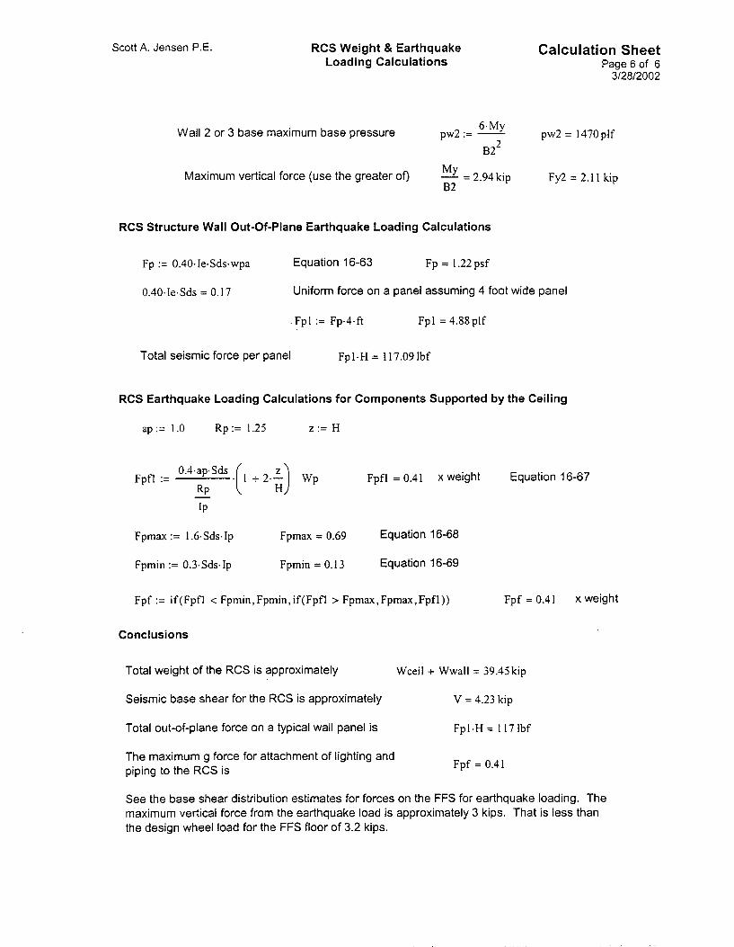
Scott A. Jensen P.E. RCS Weight & Earthquake Loading Calculations
Calculation Sheet Page6of 6
312812002
6.My pw2 = 1470plf Wall 2 or 3 base maximum base pressure pw2 := -
MY - = 2.94 kip B2
B22
Fy2 = 2.1 1 kip Maximum vertical force (use the greater of)
RCS Structure Wall Out-0f-Plane Earthquake Loading Calculations
Fp := 0.40.Ie.Sds.wpa Equation 16-63 Fp = 1.22 psf
0.40.Ie.Sds = 0.17 Uniform force on a panel assuming 4 foot wide panel
. Fpl := Fp.4.ft Fpl = 4.88plf
Total seismic force per panel Fp1.H = 117.09 Ibf
RCS Earthquake Loading Calculations for Components Supported by the Ceiling
ap:= 1.0 Rp := 1.25 z := H
~ p f l = 0.41 x weight Equation 16-67 0.4.ap.Sds .( ;) Fpfl := I + 2.- WP
RP -
Fpmax := 1.6.Sds.I~ Fpmax = 0.69 Equation 16-68
Fpmin := 0.3.Sds.I~ Fpmin = 0.13 Equation 16-69
Fpf := if(Fpfl < Fpmin,Fpmin,if(Fpfl > Fpmax,Fpmax,Fpfl)) Fpf = 0.41 x weight
Conclusions
Total weight of the RCS is approximately Wceil + Wwall = 39.45 kip
Seismic base shear for the RCS is approximately V = 4.23 kip
Total out-of-plane force on a typical wall panel is Fpl-H = 117 Ibf
The maximum g force for attachment of lighting and piping to the RCS is Fpf = 0.41
See the base shear distribution estimates for forces on the FFS for earthquake loading. The maximum vertical force from the earthquake load is approximately 3 kips. That is less than the design wheel load for the FFS floor of 3.2 kips.

Appendix G
Form 540.04 Certificate of Conformance

540.04 CERTIFICATE OF CONFORMANCE 02/07/2002 Rev. 03
NOTE: Prior to completing this certification, the Supplier shall review and comply with the attached form instructions.
. PO No.:
. Contract No.:
2. PO Rev No.: :3. PO Line Item:
5. Contract Amendment No.:
1. SupplierlSource Information
I. Supplier:
) . CodeIStandard No.:
0. Specification No.:
1. Technical DrawingslDiagrams:
2. Other:
;. Source of Origin:
Street:
City:
State:
Country:
RevisionsIEditionslAddendum:
RevisionlEditions:
Revision:
RevisionslEditionslAddendum:
~~
7. Supplier Address (StreeVCitylState):
CAUTION:
The suppliers shall take all necessary actions and precautions
to assure that this Certificate of Conformance(C of C) is accurate,
complete, and true, regardless of the actual source of origin.
1. Approved ChangeslDeviationsNVaiverslSubstitutionslNonconformances:
I . Nonconformance(s): Unless otherwise directed in writing by the Procurement Agent, Do materialslitemslequipment i f there are any changes, deviations, substitutions, or nonconforming conditions that have not been previously submitted and approved utilizing Contractor Form 540.16, Interface Document.
deliverlship
:. Certification Statement
(Supplier), hereby certifies that the materials/items/equipment identified in Section A above, and all required documentation, conforms in all respects to the stated Purchase OrderlContract requirements and that all exceptions, waivers, deviations, and/or nonconforming conditions are identified in Section D. Furthermore, information provided is accurate, complete, and true pursuant to 10 CFR 820.1 1 (see definition).
Authorized Certifying Official (See Definitionsllnstructions):
Printed Name Signature Title Date
See Instructions
C of C is Limited To One Page. Attached Additional Pages On Supplier Letter Head If Required.

540.04 02/07/2002 Rev. 03
CERTIFICATE OF CONFORMANCE
instructions General
Prepare a Certificate of Conformance (C of C) addressing each Purchase Order fine item, Contract Deliverable, and/or each partial shipment. Unless otherwise specified, the C of C shall accompany each shipment. All applicable form entries must be completed.
A Supplier system-generated C of C may be attached and referenced. All applicable information required on form 540.04 shall be accounted for. Section A and Section F shall be completed in their entirety, regardless of any attachrnents used.
Definitions
Authorized Company Certifying Official. The certification shall be attested to by an authorized represlentative of the supplier; and the certification system, including the procedures for completing, reviewing, and approving the certificate shall be described in the Company’s administrative control system.
Cerfification. The act of determining, verifying, and attesting in writing to the qualifications of personnel, processes, procedures, or items in accordance with specified requirements.
Certificate of Conformance. A document signed or otherwise authenticated by an authorized individual certifying the degree to which items or services meet specified requirements.
IO CFR 820.11. Procedural Rules for DOE Nuclear Activities, Subpart “ A , Information requirements. The regulation states:
(a) Any information pertaining to a nuclear activity provided to DOE by any person or maintained by any person for inspection by DOE shall be complete and accurate in all material respects. (b) No person involved in a DOE nuclear activity shall conceal or destroy any information concerning a violation of a DOE Nuclear Safety Requirement, a Nuclear Statute, or the Act.
Instructions
Section A, Purchase Order(P0)IContract Data
Entry 1 Enter the complete INEEL Purchase Order (PO) number.
Entry 2
Entry 3
Entry 4
Enter PO Revision Number (if applicable).
Enter the PO Line Itern Number, i.e., 1, 2 , 3 , etc ....
Enter the INEEL Contract Number (if not a PO).
Entry 5
Section B, SupplierlSource information
Entry 6
Entry 7
Enter the latest Contract Amendment Number (if applicable).
Enter the legal Supplier company name, as stated on the PO or Contract.
Enter the Supplier business address, as stated on the PO or Contract.
Entry 8 Enter the point of shipping origin by city, state, and country if different than Block 7. The point of origin shall be the originating location from which final ShipmenVdelivery to the INEEL is made. If different than Block 7, see CAUTION statement.
Section C, Applicable Requirements
Entry 9 Enter the applicable design code or consensus standard and revision, edition, or addendum.
Entry 10
Entry 11
Entry 12
Enter the applicable specification and revision, edition, or addendum.
Enter the applicable technical drawingldiagram and applicable revision, edition, or addendum.
Enter Other applicable requirements documents and revision, edition, or addendurn.

540.04 02/07/2002
CERTIFICATE OF CONFORMANCE Rev. 03
Section D, Approved Changes/DeviationsMlaivers/Substitutions/Nonconformances
Enter any approved changes. Reference change documentation control numbers as applicable. (Attach additional pages if necessary).
Section E, Nonconformance(s)
Self Explanatory.
Section F, Certification Statement (see definitions)
Enter the Company name (or commonly used acronym).
Print or type the authorized company certifying officials name, title, and date.
Affix certifying official signature (indelible ink only - no stamps).