a distributed framework for monocular visual slamceur-ws.org/vol-1964/ma1.pdf · a distributed...
TRANSCRIPT

A distributed framework for monocular visual SLAM
Ruwan Egodagamage, Mihran TuceryanDepartment of Computer and Information ScienceIndiana University Purdue University Indianapolis
Indianapolis, Indiana 46202, USAEmail: {rjegodag, tuceryan}@iupui.edu
AbstractIn Distributed Simultaneous Localization and Map-ping (SLAM), multiple agents generate a globalmap of the environment while each performing itslocal SLAM operation. One of the main challengesis to identify overlapping maps, especially whenagents do not know their relative starting positions.In this paper we are introducing a distributed frame-work which uses an appearance based method toidentify map overlaps. Our framework generates aglobal semi-dense map using multiple monocularvisual SLAM agents, each localizing itself in thismap.
1 IntroductionIn Simultaneous Localization and Mapping (SLAM), anagent creates a map of an unknown environment, at the sametime localizing itself in it. These two tasks, cannot be solvedindependent to each other. An accurate estimation of the poseis required, to build a map. At the same time, a good map isrequired for agent localization.
In certain applications such as indoor tracking, there couldbe multiple agents moving in a given environment. Theagents (cameras for our purposes in this paper) can enter andexit the environment at any time. The environment may beunknown. If there is a map of the environment, the agentscan utilize it to localize themselves in it. If an agent moves ina part of the environment that is not mapped, it can start build-ing the map and localize itself in it as part of the SLAM pro-cess. Each agent can do this independently, however, whenthey are operating in a common environment, it makes senseto use their locally built maps to complement each other andcomplete and/or improve the global map and, therefore, helpeach other in their respective tasks.
One can use a camera as the only input device to performVisual SLAM. Ubiquitous cameras (e.g., on mobile devices)make visual SLAM a more popular choice. However, cam-eras impose an additional challenge since they provide bear-ing only data. In recent work, both feature based and feature-less direct methods are used in visual SLAM. Direct methodslike [Engel et al., 2014] generate denser maps. Dense mapscan be more attractive in certain applications, such as aug-mented reality, in which a user is interacting with the envi-
ronment and virtual objects in the environment. It is desirablethat this interaction be realistic and seamless. A dense mapof the environment makes this interaction possible.
Additionally, using multiple agents to perform SLAM in-creases the robustness of SLAM process and makes it morefault tolerant and less vulnerable for catastrophic failures.One of the main challenges in distributed SLAM is to com-pute map overlaps, especially when agents have no priorknowledge of their relative starting positions. Usually agentsalso have limited bandwidth to communicate with each other.
In this paper we introduce a distributed framework formonocular visual SLAM agents with no initial knowledge oftheir relative positions.
2 Related Work
2.1 Visual SLAM
Building a 3D map of the environment from motion has beenstudied in computer vision under the name of structure frommotion [Faugeras and Lustman, 1988; Sturm and Triggs,1996]. However, this 3D scene structure estimated from mo-tion does not necessarily mean that the result is a coherentglobal map. In SLAM this is accomplished by “loop closure”in which features or structures already seen before are usedto refine the map as well as correct the camera’s path and,therefore, the localization.
Davison et al. introduced a visual SLAM method of cap-turing the path of a freely moving camera (6 Degrees of Free-dom — DoF), while generating a sparse map [Davison etal., 2007]. The method was called Monocular visual SLAM(MonoSLAM). MonoSLAM is limited to work in a room-sized environment. A more robust method called ParallelTracking and Mapping (PTAM) was introduced by Klein etal. in [Klein and Murray, 2007]. It focused on accurate andfast mapping in a similar environment to MonoSLAM.
In contrast to feature based methods, recent MonocularSLAM work, DTAM by Newcombe et al. in [Newcombeet al., 2011] and LSD-SLAM by Engel et al. [Engel et al.,2014], utilize image pixel intensities directly, and generatedense or semi-dense maps of the environment. These mapsdescribe the environment better. And, generally, they aremore robust to blur.
Ruwan Egodagamage and Mihran Tuceryan MAICS 2017 pp. 55–61
55

2.2 Distributed SLAMMultiple agents in a distributed SLAM system could be han-dled using a naive brute-force method, where nodes com-municate all sensor observations and map updates with eachother in a complete graph topology. However, the communi-cation bandwidth and computational resources available foran agent are typically limited and the distributed network issubject to failures of nodes and links. So it is necessary tocome up with an intelligent approach to cope with these chal-lenges.
A unique, globally consistent map can be easily generated,if the agents know either their relative locations or map over-laps. For example, in [Nettleton et al., 2006] relative loca-tions of the agents are found by global positioning sensors(GPS). It is also relatively easier to determine map overlapsif all relative initial poses of agents are known. For example,Paull et al. in [Paull et al., 2015] initialize agents with knownGPS location information.
The problem becomes more difficult if the relative loca-tions of the agents are unknown. In some contributions,agents continue building local sub maps until the agents meeteach other. Howard et al. [Howard et al., 2006] propose amethod where each agent could detect the other agents. Theagents use these coincidental encounters to find their relativelocations. Dieter Fox et al. in [Fox et al., 2006] present amethod where each agent is actively seeking the other agentsin the environment to find relative locations between them.
We used our experimental framework for distributedSLAM [Gamage and Tuceryan, 2016] for the developmentof the methods in this paper.
3 MethodologyThe distributed computing framework is implemented ascomputing nodes that communicate with each other over anetwork. The nodes have different computing tasks depend-ing on what their function is.
3.1 The distributed SLAM frameworkWe have two types of nodes in our distributed framework, ex-ploring nodes and monitoring nodes. Nodes are physicallylocated in different computers. They communicate with eachother using the underlying computer network. At any giventime, there is one monitoring node and multiple exploringnodes. Each node has a unique identifier. The exploringnodes are linked to the monitoring node and exploring nodesmay be linked to each other if their maps overlap resulting ina network of nodes as shown in Figure 1.
The exploring nodes perform monocular visual SLAM.Each node receives images from a single camera. Also thesenodes receive data and commands from the monitoring node.They exchange data between each other and they send datato the monitoring node. Our framework adapted the monoc-ular visual SLAM work by [Engel et al., 2014] in exploringnodes. The details of the exploring nodes are described insection 3.3.
The monitoring node continuously receives data from ex-ploring nodes. By looking at the maps of exploring nodes, it
M
EE
EE
Figure 1: The network of nodes, all exploring nodes (E) areconnected to the monitoring node (M). Some exploring nodesare also connected to each other
detects map overlaps and loop closures. Accordingly, it is-sues commands to relevant exploring nodes. The details ofthe monitoring nodes are described in section 3.2.
The Robot Operating SystemWe use the ROS infrastructure [Quigley et al., 2009] to im-plement the distributed SLAM framework. A ROS node is re-sponsible of performing computations. ROS also provides amessage passing communication framework between nodes.Nodes in our framework are implemented as ROS nodes.
In its communication framework, ROS provides namedcommunication buses called topics. Multiple nodes can pub-lish messages to a topic while multiple subscribed nodescould receive them. Based on the requirement, ROS couldeither use UDP or TCP for message passing. In our frame-work data and commands are communicated between nodesas ROS messages.
ROS has a master server to list all available topics of a sys-tem. After identifying providers and subscribers of a topic bycommunicating with master server, ROS nodes can commu-nicate with each other, peer-to-pear via topics.
The MapIn our framework, a map is represented using a set ofkeyframes in a pose graph.
The ith keyframe, Ki consists of an absolute pose ⇠Wi, animage Ii, an inverse depth map Di, an inverse depth variancemap Vi, and a list of features f
(n)i . Each keyframe gets a
globally unique 32 bit identifier as shown in Algorithm 1.
Algorithm 1 Unique identifier for a keyframe1: procedure GETUNIQUEID(keyframe id, node id)2: id SHIFTLEFT(node id, 20)3: id id+ keyframe id4: return id . A globally unique identifier5: end procedure
The pose graph contains edges, "ji, having similarity trans-formation ⇠ji 2 R7 and corresponding covariance matrix⌃ji, between ith and jth key frames as shown in Figure 2.The relative pose between the two nodes is encoded withthree components of the translation and the four componentsof the quaternion.
3.2 Monitoring nodesThe monitoring node contains a feature store to collect all theSURF [Bay et al., 2008] features (and SIFT [Lowe, 2004]
A Distributed Framework for Monocular Visual SLAM pp. 55–61
56
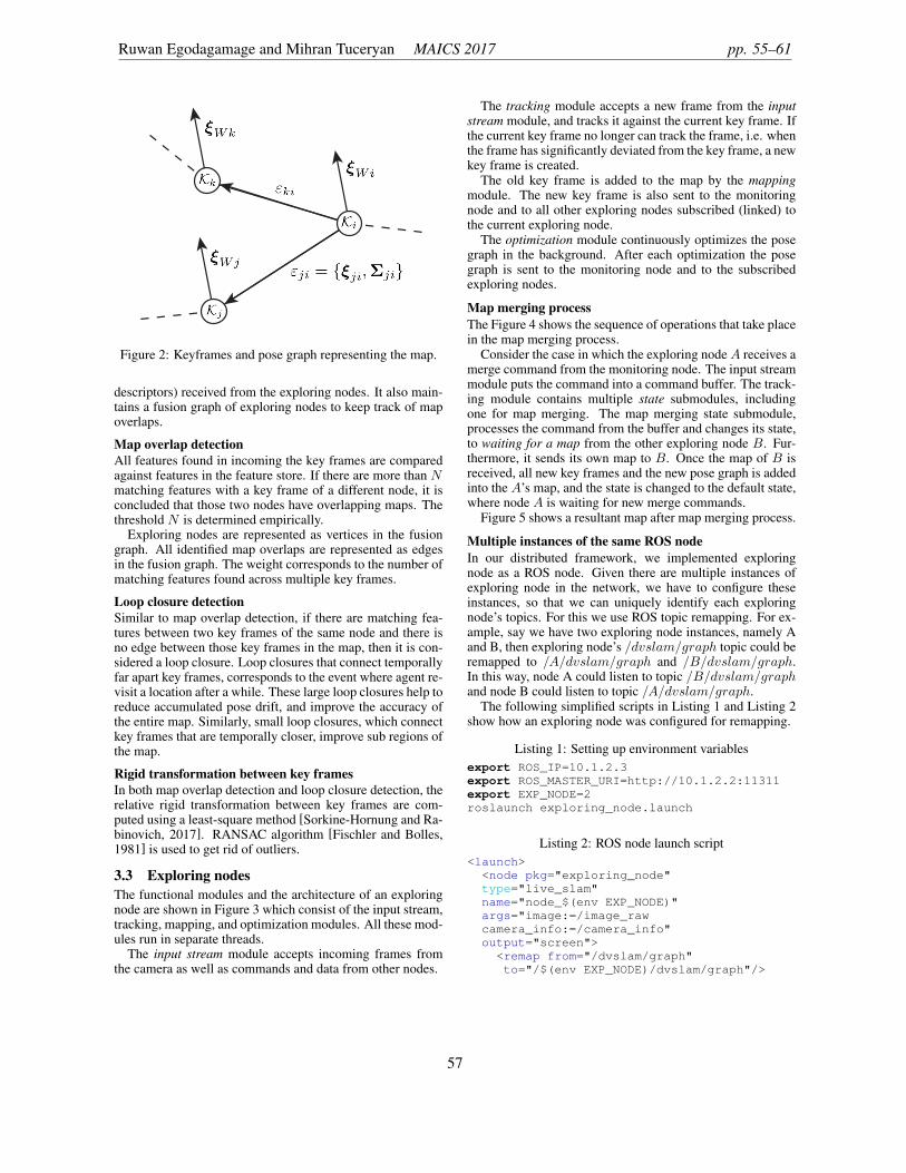
Figure 2: Keyframes and pose graph representing the map.
descriptors) received from the exploring nodes. It also main-tains a fusion graph of exploring nodes to keep track of mapoverlaps.
Map overlap detectionAll features found in incoming the key frames are comparedagainst features in the feature store. If there are more than Nmatching features with a key frame of a different node, it isconcluded that those two nodes have overlapping maps. Thethreshold N is determined empirically.
Exploring nodes are represented as vertices in the fusiongraph. All identified map overlaps are represented as edgesin the fusion graph. The weight corresponds to the number ofmatching features found across multiple key frames.
Loop closure detectionSimilar to map overlap detection, if there are matching fea-tures between two key frames of the same node and there isno edge between those key frames in the map, then it is con-sidered a loop closure. Loop closures that connect temporallyfar apart key frames, corresponds to the event where agent re-visit a location after a while. These large loop closures help toreduce accumulated pose drift, and improve the accuracy ofthe entire map. Similarly, small loop closures, which connectkey frames that are temporally closer, improve sub regions ofthe map.
Rigid transformation between key framesIn both map overlap detection and loop closure detection, therelative rigid transformation between key frames are com-puted using a least-square method [Sorkine-Hornung and Ra-binovich, 2017]. RANSAC algorithm [Fischler and Bolles,1981] is used to get rid of outliers.
3.3 Exploring nodesThe functional modules and the architecture of an exploringnode are shown in Figure 3 which consist of the input stream,tracking, mapping, and optimization modules. All these mod-ules run in separate threads.
The input stream module accepts incoming frames fromthe camera as well as commands and data from other nodes.
The tracking module accepts a new frame from the inputstream module, and tracks it against the current key frame. Ifthe current key frame no longer can track the frame, i.e. whenthe frame has significantly deviated from the key frame, a newkey frame is created.
The old key frame is added to the map by the mappingmodule. The new key frame is also sent to the monitoringnode and to all other exploring nodes subscribed (linked) tothe current exploring node.
The optimization module continuously optimizes the posegraph in the background. After each optimization the posegraph is sent to the monitoring node and to the subscribedexploring nodes.
Map merging processThe Figure 4 shows the sequence of operations that take placein the map merging process.
Consider the case in which the exploring node A receives amerge command from the monitoring node. The input streammodule puts the command into a command buffer. The track-ing module contains multiple state submodules, includingone for map merging. The map merging state submodule,processes the command from the buffer and changes its state,to waiting for a map from the other exploring node B. Fur-thermore, it sends its own map to B. Once the map of B isreceived, all new key frames and the new pose graph is addedinto the A’s map, and the state is changed to the default state,where node A is waiting for new merge commands.
Figure 5 shows a resultant map after map merging process.
Multiple instances of the same ROS nodeIn our distributed framework, we implemented exploringnode as a ROS node. Given there are multiple instances ofexploring node in the network, we have to configure theseinstances, so that we can uniquely identify each exploringnode’s topics. For this we use ROS topic remapping. For ex-ample, say we have two exploring node instances, namely Aand B, then exploring node’s /dvslam/graph topic could beremapped to /A/dvslam/graph and /B/dvslam/graph.In this way, node A could listen to topic /B/dvslam/graphand node B could listen to topic /A/dvslam/graph.
The following simplified scripts in Listing 1 and Listing 2show how an exploring node was configured for remapping.
Listing 1: Setting up environment variablesexport ROS_IP=10.1.2.3export ROS_MASTER_URI=http://10.1.2.2:11311export EXP_NODE=2roslaunch exploring_node.launch
Listing 2: ROS node launch script<launch>
<node pkg="exploring_node"type="live_slam"name="node_$(env EXP_NODE)"args="image:=/image_rawcamera_info:=/camera_info"output="screen">
<remap from="/dvslam/graph"to="/$(env EXP_NODE)/dvslam/graph"/>
Ruwan Egodagamage and Mihran Tuceryan MAICS 2017 pp. 55–61
57

OptimizationMapping
TrackingInput Stream
Exploring Node Monitoring Node
fusion graph
feature store
CameraFrames
Key frames
Pose graph
Commands &Data
Map
Receiving map from another exploring node
Incremental map updating after merging
Figure 3: The distributed SLAM framework. Returning dashed arrows represent communication between two exploring nodes.
<remap from="/dvslam/keyframes"to="/$(env EXP_NODE)/dvslam/keyframes"/>
</node></launch>
3.4 Communication between nodesNodes use ROS topics and messages to issue commands andto exchange data. Four topics named, keyframes, graph, com-mand and map are used in the framework. These topics arefully-qualified using the namespace /dvslam/.
ROS topics used in the framework are shown in Table 1.The publisher node writes data and subscriber nodes receivethe data via the topic.
Network statisticsA distributed SLAM could easily reach the bandwidth limi-tations of a network, especially, when dense maps are trans-ferred between nodes. In our distributed framework we couldgenerate statistics by using ROS Topic Statistics.
The measurement of traffic volume in bytes of every con-nection between nodes helps us to identify bandwidth uti-lization. Furthermore, measurements like number of droppedmessages between nodes is a good indication of reaching thebandwidth limit. Other statistics such as mean & standarddeviation of the age of messages, and period of messages ofall nodes can also be used to investigate the communicationbetween nodes.
4 Experimental Results4.1 The experimental setupOur experimental setup is designed to precisely define theground truth against which the estimated camera positions
along the motion path can be measured. To test our frame-work we mounted a global shutter camera, Point Grey Fire-fly MV, on a Computer Numeric Control (CNC) machine asshown in Figure 6. We then prepared a 1m ⇥ 1.5m tablesurface containing wooden objects. We then moved the cam-era above the wooden objects, roughly 4 minutes each time,along known paths and captured both the image stream andthe ground truth from the CNC controller. The CNC machinehas 0.2mm accuracy in all 3 axes. The camera operated in640⇥ 480 pixel resolution. To capture ground truth from thetiny CNC controller, we wrote an open source ROS node in[Egodagamage, 2017].
4.2 Running experimentsWe defined two different 3D paths with 10% overlap, PathA
and PathB with two different known starting points A andB respectively. Next, we collected four datasets, with twodifferent camera orientations for each path. We created twoexperiments. In the first experiment, we selected two datasetshaving parallel camera optical axes. In the second experimentwe used remaining two datasets, where the optical axes is40� to each other. Each dataset is used to deploy an exploringnode.
In each experiment, two exploring nodes and one monitor-ing node are used. These nodes are deployed in three differentcomputers. Once the framework detected map overlaps, werecorded the relative transformation between the maps of ex-ploring nodes. Each experiment is repeated 100 times. Theaverage transformation for each experiment is then comparedagainst the ground truth to compute errors in rotation andtranslation.
In both experiments, resultant rotation errors in translation
A Distributed Framework for Monocular Visual SLAM pp. 55–61
58

MonitoringNode
TrackingModule
Input StreamModule
Buffers
OptimizationModule
Map
ReceivedMap
OtherExploring
Node
Map
MergeCommand
State SM
Figure 4: Important components of the map merging process
Topic Publisher Subscriber Descriptionkeyframes Exploring node Monitoring node
Exploring nodeMonitoring nodes always receive key frames from all exploringnodes. After merging maps, exploring nodes exchange key framesbetween each other.
graph Exploring node Monitoring nodeExploring node
Monitoring nodes always receive pose graph from all exploringnodes. After merging maps, exploring nodes exchange pose graphsbetween each other.
command Monitoring node Exploring node All exploring nodes process commands addressed to them and dis-card others. Commands like map merging, loop closure is receivedvia this topic.
map Exploring node Exploring node During the merge process, relevant exploring nodes subscribe eachothers’ map topic and unsubscribe once done.
Table 1: ROS topics used to communicate between nodes
Experiment Rotation Error Translation ErrorExperiment 1 3.799� 1.959cmExperiment 2 5.330� 2.754cm
Table 2: Summary of the experimental results.
and rotation were less than 3cm and 6� respectively as shownin Table 2.
5 Conclusion & Future WorkIn this paper, we have introduced a distributed framework forvisual SLAM, with no knowledge of relative starting posi-tions of exploring nodes. We have tested our framework usingtwo experiments. Each experiment was repeated 100 times tocompute the relative transformation between maps of two ex-ploring nodes. We found that, the error from the ground truthwas less than 3cm in calculating the translation between mapsand less than 6� in calculating the rotation.
As future work, we will be working on supporting morethan two exploring nodes. We will also be working on meth-
ods to recover random node failures. Moreover, we will beconducting more experiments on network bandwidth utiliza-tion.
References[Bay et al., 2008] Herbert Bay, Andreas Ess, Tinne Tuyte-
laars, and Luc Van Gool. Speeded-up robust features(surf). Comput. Vis. Image Underst., 110(3):346–359,June 2008.
[Davison et al., 2007] A.J. Davison, I.D. Reid, N.D. Molton,and O. Stasse. Monoslam: Real-time single camera slam.Pattern Analysis and Machine Intelligence, IEEE Transac-tions on, 29(6):1052–1067, June 2007.
[Egodagamage, 2017] Ruwan J Egodagamage. An opensource ros node for tinyg motion controller. https://github.com/japzi/rostinyg, 2017. [Online;accessed in February 2017].
[Engel et al., 2014] Jakob Engel, Thomas Schps, and DanielCremers. Lsd-slam: Large-scale direct monocular slam.In Computer Vision ECCV 2014, volume 8690 of Lecture
Ruwan Egodagamage and Mihran Tuceryan MAICS 2017 pp. 55–61
59

Figure 5: Resultant map of an exploration node after the map merging process. The exploring node’s map and keyframes areshown in green and yellow respectively. Received map and keyframes are shown in pink and blue respectively. Constraints ofthe pose graph is not shown for clarity.
Figure 6: Experimental setup showing a camera mounted ona CNC machine allowing us to capture ground truth informa-tion.
Notes in Computer Science, pages 834–849. Springer In-ternational Publishing, 2014.
[Faugeras and Lustman, 1988] Olivier D Faugeras and Fran-cis Lustman. Motion and structure from motion in a piece-wise planar environment. International Journal of Pat-tern Recognition and Artificial Intelligence, 2(03):485–508, 1988.
[Fischler and Bolles, 1981] Martin A. Fischler and Robert C.Bolles. Random sample consensus: A paradigm for modelfitting with applications to image analysis and automatedcartography. Commun. ACM, 24(6):381–395, June 1981.
[Fox et al., 2006] D. Fox, J. Ko, K. Konolige, B. Limketkai,D. Schulz, and B. Stewart. Distributed multirobot explo-ration and mapping. Proceedings of the IEEE, 94(7):1325–1339, July 2006.
[Gamage and Tuceryan, 2016] R. Gamage and M. Tuceryan.An experimental distributed framework for distributed si-multaneous localization and mapping. In 2016 IEEE In-ternational Conference on Electro Information Technology(EIT), pages 0665–0667, May 2016.
[Howard et al., 2006] Andrew Howard, LynneE. Parker, andGauravS. Sukhatme. The sdr experience: Experimentswith a large-scale heterogeneous mobile robot team. InJr. Ang, MarceloH. and Oussama Khatib, editors, Experi-mental Robotics IX, volume 21 of Springer Tracts in Ad-vanced Robotics, pages 121–130. Springer Berlin Heidel-berg, 2006.
[Klein and Murray, 2007] G. Klein and D. Murray. Paralleltracking and mapping for small ar workspaces. In Mixedand Augmented Reality, 2007. ISMAR 2007. 6th IEEE andACM International Symposium on, pages 225–234, Nov2007.
[Lowe, 2004] David G. Lowe. Distinctive image featuresfrom scale-invariant keypoints. Int. J. Comput. Vision,60(2):91–110, November 2004.
[Nettleton et al., 2006] Eric Nettleton, Sebastian Thrun,Hugh Durrant-Whyte, and Salah Sukkarieh. Decentralised
A Distributed Framework for Monocular Visual SLAM pp. 55–61
60

slam with low-bandwidth communication for teams of ve-hicles. In Field and Service Robotics, pages 179–188.Springer, 2006.
[Newcombe et al., 2011] Richard A. Newcombe, S.J. Love-grove, and A.J. Davison. Dtam: Dense tracking andmapping in real-time. In Computer Vision (ICCV), 2011IEEE International Conference on, pages 2320–2327, Nov2011.
[Paull et al., 2015] L. Paull, Guoquan Huang, M. Seto, andJ.J. Leonard. Communication-constrained multi-auv co-operative slam. In Robotics and Automation (ICRA), 2015IEEE International Conference on, pages 509–516, May2015.
[Quigley et al., 2009] Morgan Quigley, Ken Conley, BrianGerkey, Josh Faust, Tully Foote, Jeremy Leibs, RobWheeler, and Andrew Y Ng. Ros: an open-source robotoperating system. In ICRA workshop on open source soft-ware, volume 3, page 5, 2009.
[Sorkine-Hornung and Rabinovich, 2017] Olga Sorkine-Hornung and Michael Rabinovich. Least-squares rigidmotion using svd. 2017. Available at https://igl.ethz.ch/projects/ARAP/svd_rot.pdf.
[Sturm and Triggs, 1996] Peter Sturm and Bill Triggs. Afactorization based algorithm for multi-image projectivestructure and motion. In European conference on com-puter vision, pages 709–720. Springer, 1996.
Ruwan Egodagamage and Mihran Tuceryan MAICS 2017 pp. 55–61
61