a direct micromechanics method for analysis of failure initiation of plain weave textile composites
TRANSCRIPT
COMPOSITES
Composites Science and Technology 66 (2006) 137–150
SCIENCE ANDTECHNOLOGY
www.elsevier.com/locate/compscitech
A direct micromechanics method for analysis of failure initiationof plain weave textile composites
Ryan L. Karkkainen 1, Bhavani V. Sankar *
Mechanical and Aerospace Engineering Department, University of Florida, 231 MAE-A Building, P.O. Box 116250, Gainesville,
FL, 32611-6250, United States
Received 11 November 2004; received in revised form 5 April 2005; accepted 19 May 2005Available online 14 July 2005
Abstract
A micromechanical analysis of the representative volume element (RVE) of a plain weave textile composite has been performedusing the finite element method. Stress gradient effects are investigated, and it is assumed that the stress state is not uniform acrossthe RVE. This is unlike most stiffness and strength models, which start with the premise that an RVE is subjected to a uniform stressor strain. For textile geometries, non-uniform stress considerations are important, as the size of a textile RVE will typically be sev-eral orders of magnitude larger than that of a unidirectional RVE, for which many analysis techniques are developed. The stressstate is defined in terms of the well-known laminate theory force and moment resultants [N] and [M]. Structural stiffness coefficientsanalogous to the [A], [B], [D] matrices are defined, and these are computed directly using the direct micromechanics method (DMM),rather than making estimations based upon homogenized properties. Failure envelopes for a plain-weave textile composite havebeen constructed. Transverse failure of the fiber tow was the dominant mode of initial failure. The DMM failure envelope comparedclosely to the Tsai-Wu failure theory, but was more conservative in some areas.� 2005 Elsevier Ltd. All rights reserved.
Keywords: A. Textile Composites; B. Strength; C. Finite element analysis
1. Introduction
Current failure theories are generally developed forunidirectional composites and do not capture the uniquecharacteristics of textile composites. Though these theo-ries may to some extent be applied in an adapted form tothe analysis of textile composites, many inherent simpli-fying assumptions will no longer apply, and in generalsuch techniques will not be suitable to the increasedcomplexity intrinsic to textile geometry. Even at the mi-cro scale, textile composites maintain a relatively com-
0266-3538/$ - see front matter � 2005 Elsevier Ltd. All rights reserved.
doi:10.1016/j.compscitech.2005.05.018
* Corresponding author. Tel.: +1 352 392 6749; fax: +1 352 3927303.
E-mail addresses: [email protected] (R.L. Karkkainen), [email protected] (B.V. Sankar).1 Graduate Student. Tel.: +1 352 846 3027; fax: +1 352 846 3028.
plicated microstructure. Even under simple loadingconditions, a textile microstress state will be shown tobe quite complex, and elastic constants are non-uniformdue to the waviness of a woven fiber tow. Laminateanalysis, property homogenization, and other commonapproaches will no longer apply. Thus, current designsof textile structures will not be optimized for maximumdamage resistance and light-weight.
Conventional micromechanical models for textilecomposites assume that the state of stress is uniformover a distance comparable to the dimensions of the rep-resentative volume element (RVE). However, due tocomplexity of the weave geometry, the size of the RVEin textile composites can be large compared to structuraldimensions. In such cases, severe non-uniformities in thestress state will exist, and conventional models may fail.Such stress gradients also exist when the load is applied
Nomenclature
rM macroscopic level stressre element level stressri normal stress in the i directionsxy shear stress in the x–y planea RVE widthb RVE depthc RVE heightNi force resultant in the i directionNxy shear force resultant in the x–y planeMi moment resultant in the i directionMxy torque resultant in the x–y planeei normal strain in the i directioncxy shear strain in the x–y planeji curvature in the i directionjxy twist in the x–y direction[A] in-plane stiffness matrix[B] strain-curvature coupling matrix[D] flexural stiffness matrix
z distance from RVE midplane in the heightdirection
E Young�s modulusG shear stiffnessm Poisson ratioVf fiber volume fractionVe element volumeu displacementHij deformation gradientsXT maximum force resultant before failure in
tension in the x-directionXC maximum force resultant before failure in
compression in the x-directionYT maximum force resultant before failure in
tension in the y-directionYC maximum force resultant before failure in
compression in the y-directionS maximum in-plane shear force resultant
before failure
138 R.L. Karkkainen, B.V. Sankar / Composites Science and Technology 66 (2006) 137–150
over a very small region, as in static contact or foreignobject impact loading, and when there are stress concen-tration effects such as open holes in a structure.
Although micromechanical models have been suc-cessfully employed in predicting thermo-elastic con-stants of fiber-reinforced composite materials, their usefor strength prediction in multiaxial loading conditionsis not practical, as computational analysis must be per-formed in each loading case. Thus, phenomenologicalfailure criteria are still the predominant choice for de-sign in industry. There are three major types of engineer-ing failure criteria for unidirectional compositematerials: maximum stress criterion, maximum straincriterion, and quadratic interaction criterion, such asthe Tsai-Hill and Tsai-Wu failure theories [1].
Most of the micromechanical modeling work donethus far have focused on predicting thermo-mechanicalproperties [2–5]. To facilitate the use of textile compos-ites in lightweight structures, it is required to have a lu-cid understanding of failure mechanisms, and designengineers must have an accurate and practical modelfor prediction of failure stress. Most of the current ana-lytical and numerical methodologies developed to char-acterize textile composites [6–13] assume that the textileis a homogeneous material at the macroscopic scale.
Finite element analysis of initial failure of a plainweave composite [9] has shown that failure due to in-ter-tow normal stresses are the predominant mode offailure, and there is generally little or no damage volumeof the bulk matrix between tows. This work is extendedto a thorough investigation of progressive failure analy-sis under axial extension using several different property
knockdown schemes. This has shown stiffness losses onthe order of 40% after initial failure. More recently thiswork has been extended to include the capability formore detailed stress fields in the RVE under investiga-tion [14], and techniques have been developed to mini-mize required computation times by employingboundary conditions based on thorough exploitationof symmetry and periodicity of RVE geometry [15].
The BinaryModel [16,17] allows for quick and efficientfinite element analysis of any textile weave of interest.Fiber tows are modeled simply and reasonably as embed-ded 1-D line elementswithin the bulkmatrix. Thismethodhas been shown to provide for accurate prediction of stiff-ness properties. Further, it is robust and readily adaptableto provide insight into effects of alteration of parameterssuch as tow waviness, tow misalignment, varying weavearchitectures, etc. This technique does not yield a detailedmap of RVE stress fields or allow for cross-sectional var-iation of tow geometry, as the fiber tow is simulated as a1-D line element with representative material properties.Thus, somemicro-level detail is lost to provide for compu-tational efficiency and macro-level representation.
The Mosaic Model and its adaptations [6,18,19] rep-resent a textile composite RVE as a collection of homog-enized blocks, each with unidirectional composite ormatrix properties. These blocks are then assembled torepresent the weave geometry under consideration. Inthis way, classical laminate plate theory can be used todetermine the global stiffness matrix of the RVE. Formacroscopically homogeneous load cases, good agree-ment has been shown with experimental data, includingthree-dimensional weave geometries.

R.L. Karkkainen, B.V. Sankar / Composites Science and Technology 66 (2006) 137–150 139
Effective prediction of compressive strength ofbraided textile composites using a detailed FEM micro-mechanical model has been performed [20], which showsgood comparison to experimental results in a parallelstudy [21]. A detailed 3D solid model was formed to ex-actly model a 2D triaxially braided composite RVE.Biaxial loading is considered in both the experimentaland computational analyses. Buckling analysis has beenperformed, and the effects of tow waviness and microar-chitecture on the compressive strength are shown.
For uniaxially loaded textile composites, consistentbut optimistic strength estimates have been made bycomparing the strength of fiber tows with the predictedstresses in the fiber yarns that are aligned with the load-ing axis [22–24]. The off-axis tows are given little consid-eration, without much effect on the outcome, as theyplay little part in such uniaxial loading cases. Multi-axialloading presents an obvious escalation in modeling com-plexity. The failure envelope for combined transversetension and in-plane shear has been presented as an el-lipse [25], according to quadratic strength rules devel-oped for unidirectional composites. Further, proposalsfor multiaxial loadings submit that axial strain in thetextile geometry should be compared to a critical valueof tow strain, analogous to a first-ply failure criterionfor unidirectional composites [26].
A previous study by the authors [27] extended amethod, known as the direct micromechanics method(DMM) [28], to develop failure envelopes for a plain-weave textile composite under plane stress in terms ofapplied macroscopic stresses. In this study, it was as-sumed that the state of stress is uniform across theRVE. The micro scale stresses within the RVE werecomputed using finite element methods. The relation be-tween the average macrostress and macrostrains providethe constitutive relations for the idealized homogeneousmaterial. The microstresses are used to predict the fail-ure of the yarn or matrix, which in turn translates tofailure of the textile composite.
In the current paper, micromechanical finite elementanalysis is performed to determine the constitutive rela-tions and failure envelope for a plain-weave graphite/epoxy textile composite. The model is based upon theanalysis of an RVE, which is subjected to force and mo-ment resultants of classical laminate theory. Thus, thereis no assumption about the uniformity of an appliedload or strain, as any load can be represented by acombination of force and moment resultants. The micro-scale stresses within the RVE are computed using the fi-nite element method. The relation between the averagemacrostress and macrostrains provide the constitutiverelations for the material. Thus constitutive character-ization matrices [A], [B], [D] are found directly frommicromechanics. The microstresses are also used to pre-dict the failure of the yarn or matrix, which in turntranslates to failure of the textile composite. Using the
DMM, the failure envelope is developed for in-planeforce resultants, with and without applied momentresultants. No currently accepted failure criteria existthat may be used explicitly for the analysis of textilecomposites. Thus, the methods and results employedherein are used to develop phenomenological failure cri-teria for textile composites. The results are compared toconventional failure envelopes that are not specificallydeveloped for the analysis of textile composites, as a ba-sis for evaluation.
2. Methods
2.1. Finite element micromechanical method
In the current study, stress gradient effects are inves-tigated, and it is assumed that the stress state is not uni-form across the RVE. This represents an extension ofthe micromechanical models used to predict the strengthof textile composites [27–31]. The stress state is definedin terms of the well-known laminate theory load matri-ces [N] and [M], i.e., force and moment resultants. Fur-thermore, structural stiffness coefficients analogous tothe [A], [B], [D] matrices are defined. In this approach,these structural stiffness coefficients are computed di-rectly from the micromechanical models, rather thanmaking estimations based upon the homogeneousYoung�s modulus and plate thickness, i.e., individualunit strains and unit curvatures can be applied to themicromechanical finite element model, and the resultingdeformations are used to define the stiffness coefficientmatrices. Conventional models essentially neglect thepresence of [M] terms that result from non-uniformityor gradients in applied force resultants, thus assuminga uniform stress state for which only the [N] matrix ispopulated. The additional analysis of the [M] term in-cludes information about the distribution, or gradient,of a non-uniform load. This can greatly increase theability of a failure model to accurately predict failurefor load cases in which such effects may well be predom-inant, such as in thin plates, concentrated loading, orimpact loading.
The significance of including the analysis of momentterms is further illustrated in Fig. 1. The moment termdescribes the distribution, not only the magnitude, of ap-plied loading. Depending on the stress state of an RVE,an analysis incorporating stress gradient effects andinclusion of the consideration of applied moment couldbe of critical importance. In Fig. 1(a), the force resultant(N) is non-zero, but the uniform loading results in zeromoment resultant (M). However, in load cases such asFig. 1(b) and (c), the non-uniformity of applied loadingleads directly to an appreciable moment term, whichmust be included in the analysis. In fact, in some casesit is possible that the net force resultant is zero while
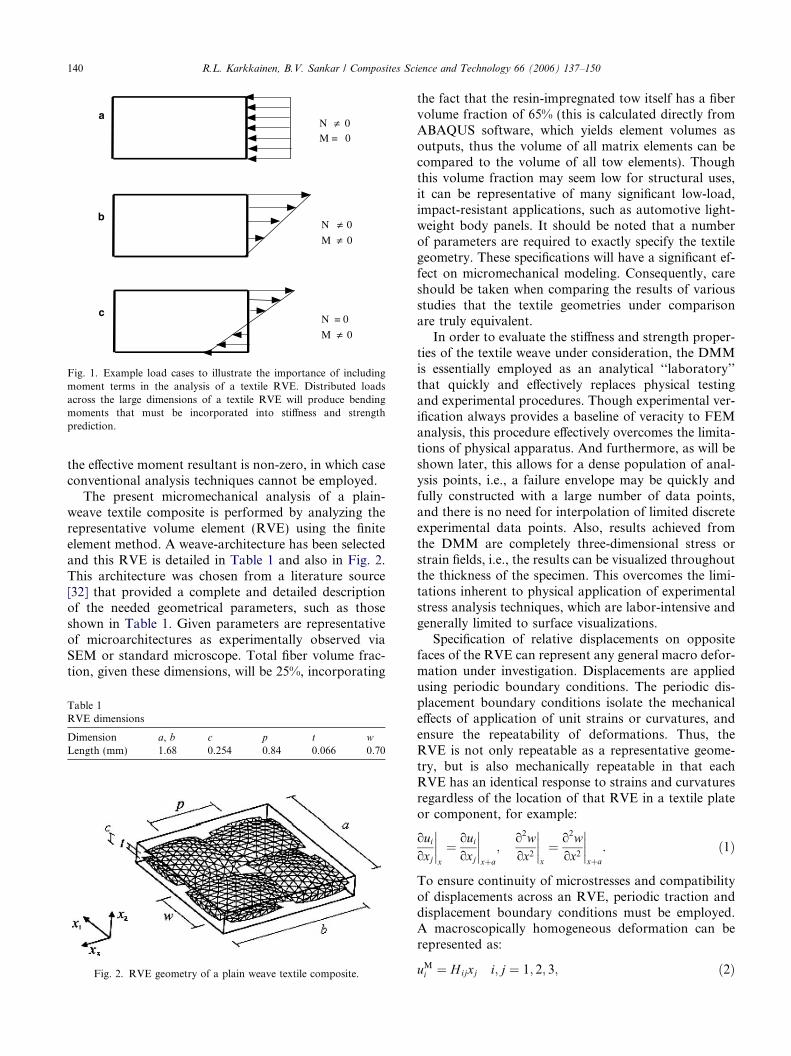
aN ≠ 0
M = 0
bN ≠ 0
M ≠ 0
cN = 0
M ≠ 0
Fig. 1. Example load cases to illustrate the importance of includingmoment terms in the analysis of a textile RVE. Distributed loadsacross the large dimensions of a textile RVE will produce bendingmoments that must be incorporated into stiffness and strengthprediction.
140 R.L. Karkkainen, B.V. Sankar / Composites Science and Technology 66 (2006) 137–150
the effective moment resultant is non-zero, in which caseconventional analysis techniques cannot be employed.
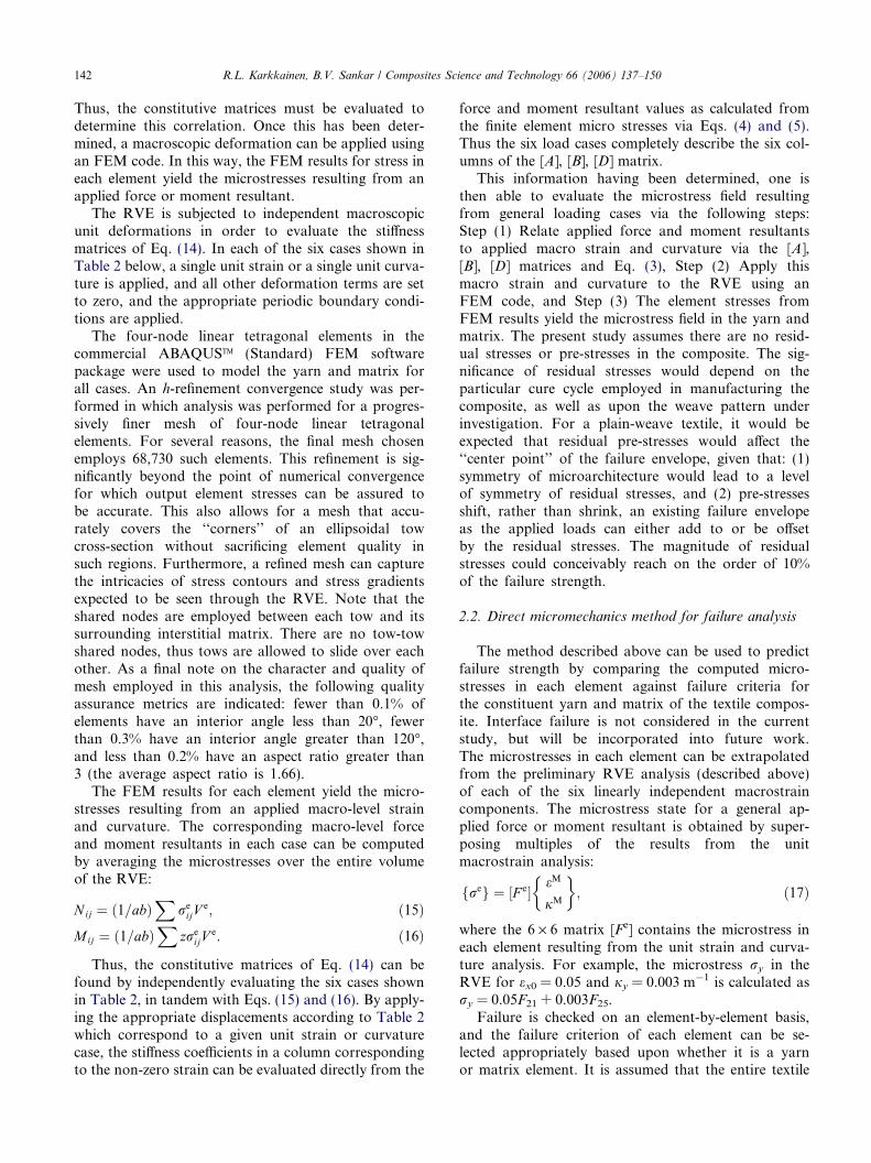
The present micromechanical analysis of a plain-weave textile composite is performed by analyzing therepresentative volume element (RVE) using the finiteelement method. A weave-architecture has been selectedand this RVE is detailed in Table 1 and also in Fig. 2.This architecture was chosen from a literature source[32] that provided a complete and detailed descriptionof the needed geometrical parameters, such as thoseshown in Table 1. Given parameters are representativeof microarchitectures as experimentally observed viaSEM or standard microscope. Total fiber volume frac-tion, given these dimensions, will be 25%, incorporating
Table 1RVE dimensions
Dimension a, b c p t w
Length (mm) 1.68 0.254 0.84 0.066 0.70
Fig. 2. RVE geometry of a plain weave textile composite.
the fact that the resin-impregnated tow itself has a fibervolume fraction of 65% (this is calculated directly fromABAQUS software, which yields element volumes asoutputs, thus the volume of all matrix elements can becompared to the volume of all tow elements). Thoughthis volume fraction may seem low for structural uses,it can be representative of many significant low-load,impact-resistant applications, such as automotive light-weight body panels. It should be noted that a numberof parameters are required to exactly specify the textilegeometry. These specifications will have a significant ef-fect on micromechanical modeling. Consequently, careshould be taken when comparing the results of variousstudies that the textile geometries under comparisonare truly equivalent.
In order to evaluate the stiffness and strength proper-ties of the textile weave under consideration, the DMMis essentially employed as an analytical ‘‘laboratory’’that quickly and effectively replaces physical testingand experimental procedures. Though experimental ver-ification always provides a baseline of veracity to FEManalysis, this procedure effectively overcomes the limita-tions of physical apparatus. And furthermore, as will beshown later, this allows for a dense population of anal-ysis points, i.e., a failure envelope may be quickly andfully constructed with a large number of data points,and there is no need for interpolation of limited discreteexperimental data points. Also, results achieved fromthe DMM are completely three-dimensional stress orstrain fields, i.e., the results can be visualized throughoutthe thickness of the specimen. This overcomes the limi-tations inherent to physical application of experimentalstress analysis techniques, which are labor-intensive andgenerally limited to surface visualizations.
Specification of relative displacements on oppositefaces of the RVE can represent any general macro defor-mation under investigation. Displacements are appliedusing periodic boundary conditions. The periodic dis-placement boundary conditions isolate the mechanicaleffects of application of unit strains or curvatures, andensure the repeatability of deformations. Thus, theRVE is not only repeatable as a representative geome-try, but is also mechanically repeatable in that eachRVE has an identical response to strains and curvaturesregardless of the location of that RVE in a textile plateor component, for example:
ouioxj
����x
¼ ouioxj
����xþa
;o2wox2
����x
¼ o2wox2
����xþa
. ð1Þ
To ensure continuity of microstresses and compatibilityof displacements across an RVE, periodic traction anddisplacement boundary conditions must be employed.A macroscopically homogeneous deformation can berepresented as:
uMi ¼ Hijxj i; j ¼ 1; 2; 3; ð2Þ

R.L. Karkkainen, B.V. Sankar / Composites Science and Technology 66 (2006) 137–150 141
e:g:; uiða; x2; x3Þ � uið0; x2; x3Þ ¼ Hi1a;
uiðx1; b; x3Þ � uiðx1; 0; x3Þ ¼ Hi2b.
The derivation of the periodic boundary condition forunit curvature is presented below, and further examplesare presented in the appendix.
The periodic displacement boundary condition corre-sponding to unit curvature along the x-axis (jx) will bederived. All other curvatures will be zero. Curvaturesare defined as follows:
jx ¼ � o2wox2
¼ 1; jy ¼ � o2woy2
¼ 0; jxy ¼ � o2woxoy
¼ 0.
ð3ÞThe periodic displacement boundary condition will bederived from the definition of curvature along the x-axis(jx). Integrating once with respect to x yields:
� owox
¼ xþ f ðyÞ; ð4Þ
where f(y) is an arbitrary function of y. Differentiationof this expression with respect to y, together with therequirement that jxy is set as zero, indicates that:
jxy ¼ � o2woxoy
¼ f 0ðyÞ ¼ 0. ð5Þ
Due to the above expression, f(y) must therefore be aconstant, since jxy = 0. Furthermore, this constant mustbe zero due to the specification that slope at the origin iszero, i.e., ow
ox jx¼0 ¼ 0. Next, Eq. (4) is integrated with re-spect to x, giving rise to the following expression and anarbitrary function h(y):
�w ¼ x2
2þ hðyÞ. ð6Þ
Now coordinate values for opposite faces of the RVE(see Fig. 2) may be substituted into Eq. (6):
wða; y; zÞ ¼ � 1
2a2 þ hðyÞ;
wð0; y; zÞ ¼ hðyÞ.ð7Þ
These are then subtracted from each other, eliminatingthe unknown h(y), and effectively prescribing the relativedisplacement on opposite faces that can be used to applyunit curvature,
Table 2Periodic displacement boundary conditions
u(a, y) � u(0, y) v(a, y) � v(0, y) W(a, y) �W(
1 eMx ¼ 1 a 0 02 eMy ¼ 1 0 0 03 cMxy ¼ 1 0 a/2 04 jMx ¼ 1 az 0 �a2/25 jMy ¼ 1 0 0 06 jMxy ¼ 1 0 az/2 �ay/2
wða; y; zÞ � wð0; y; zÞ ¼ � 1
2a2. ð8Þ
However, a further boundary condition is required toremove the transverse shear forces that will be presentdue to the application of this displacement. In thisway, the mechanical effect of curvature is isolated. Thusthe requirement is that transverse shear strain is zero,which is defined as:
czx ¼ouoz
þ owox
¼ 0. ð9Þ
This can be rearranged as below, and the value of slopeowox is known from Eq. (4) above (where the arbitraryfunction has been shown to be zero):
ouoz
¼ � owox
¼ x. ð10Þ
Similar to the above procedure, this expression can thenbe integrated with respect to z, evaluated with coordi-nate values of opposite faces, which are then subtractedfrom each other to specify the relative displacement thatmust be prescribed:
u ¼ zxþ c; ð11Þuða; y; zÞ � uð0; y; zÞ ¼ za. ð12Þ
Thus, the periodic boundary conditions as shown inEqs. (8) and (12) must be simultaneously applied to iso-late the effects of an applied unit-curvature, as seen inTable 2.
In order to satisfy equilibrium, traction boundaryconditions are applied to ensure equal and oppositeforces on opposite faces of the RVE. The tractionboundary conditions for traction forces on the lateralfaces of the RVE are:
F iða; y; zÞ ¼ �F ið0; y; zÞ;F iðx; b; zÞ ¼ �F iðx; 0; zÞ;F iðx; y; cÞ ¼ �F iðx; y; 0Þ.
ð13Þ
In DMM, the RVE is subjected to macroscopic forceand moment resultants, which are related to macro-scopic strain and curvature according to:
½N �½M �
� �¼
½A� ½B�½B� ½D�
� � ½e�½j�
� �. ð14Þ
0, y) u(x, b) � u(x, 0) v(x, b) � v(x, 0) w(x, b) � w(x, 0)
0 0 00 b 0b/2 0 00 0 00 bz �b2/2bz/2 0 �bx/2
142 R.L. Karkkainen, B.V. Sankar / Composites Science and Technology 66 (2006) 137–150
Thus, the constitutive matrices must be evaluated todetermine this correlation. Once this has been deter-mined, a macroscopic deformation can be applied usingan FEM code. In this way, the FEM results for stress ineach element yield the microstresses resulting from anapplied force or moment resultant.
The RVE is subjected to independent macroscopicunit deformations in order to evaluate the stiffnessmatrices of Eq. (14). In each of the six cases shown inTable 2 below, a single unit strain or a single unit curva-ture is applied, and all other deformation terms are setto zero, and the appropriate periodic boundary condi-tions are applied.
The four-node linear tetragonal elements in thecommercial ABAQUSTM (Standard) FEM softwarepackage were used to model the yarn and matrix forall cases. An h-refinement convergence study was per-formed in which analysis was performed for a progres-sively finer mesh of four-node linear tetragonalelements. For several reasons, the final mesh chosenemploys 68,730 such elements. This refinement is sig-nificantly beyond the point of numerical convergencefor which output element stresses can be assured tobe accurate. This also allows for a mesh that accu-rately covers the ‘‘corners’’ of an ellipsoidal towcross-section without sacrificing element quality insuch regions. Furthermore, a refined mesh can capturethe intricacies of stress contours and stress gradientsexpected to be seen through the RVE. Note that theshared nodes are employed between each tow and itssurrounding interstitial matrix. There are no tow-towshared nodes, thus tows are allowed to slide over eachother. As a final note on the character and quality ofmesh employed in this analysis, the following qualityassurance metrics are indicated: fewer than 0.1% ofelements have an interior angle less than 20�, fewerthan 0.3% have an interior angle greater than 120�,and less than 0.2% have an aspect ratio greater than3 (the average aspect ratio is 1.66).
The FEM results for each element yield the micro-stresses resulting from an applied macro-level strainand curvature. The corresponding macro-level forceand moment resultants in each case can be computedby averaging the microstresses over the entire volumeof the RVE:
Nij ¼ 1=abð ÞX
reijV
e; ð15Þ
Mij ¼ 1=abð ÞX
zreijV
e. ð16Þ
Thus, the constitutive matrices of Eq. (14) can befound by independently evaluating the six cases shownin Table 2, in tandem with Eqs. (15) and (16). By apply-ing the appropriate displacements according to Table 2which correspond to a given unit strain or curvaturecase, the stiffness coefficients in a column correspondingto the non-zero strain can be evaluated directly from the
force and moment resultant values as calculated fromthe finite element micro stresses via Eqs. (4) and (5).Thus the six load cases completely describe the six col-umns of the [A], [B], [D] matrix.
This information having been determined, one isthen able to evaluate the microstress field resultingfrom general loading cases via the following steps:Step (1) Relate applied force and moment resultantsto applied macro strain and curvature via the [A],[B], [D] matrices and Eq. (3), Step (2) Apply thismacro strain and curvature to the RVE using anFEM code, and Step (3) The element stresses fromFEM results yield the microstress field in the yarn andmatrix. The present study assumes there are no resid-ual stresses or pre-stresses in the composite. The sig-nificance of residual stresses would depend on theparticular cure cycle employed in manufacturing thecomposite, as well as upon the weave pattern underinvestigation. For a plain-weave textile, it would beexpected that residual pre-stresses would affect the‘‘center point’’ of the failure envelope, given that: (1)symmetry of microarchitecture would lead to a levelof symmetry of residual stresses, and (2) pre-stressesshift, rather than shrink, an existing failure envelopeas the applied loads can either add to or be offsetby the residual stresses. The magnitude of residualstresses could conceivably reach on the order of 10%of the failure strength.
2.2. Direct micromechanics method for failure analysis
The method described above can be used to predictfailure strength by comparing the computed micro-stresses in each element against failure criteria forthe constituent yarn and matrix of the textile compos-ite. Interface failure is not considered in the currentstudy, but will be incorporated into future work.The microstresses in each element can be extrapolatedfrom the preliminary RVE analysis (described above)of each of the six linearly independent macrostraincomponents. The microstress state for a general ap-plied force or moment resultant is obtained by super-posing multiples of the results from the unitmacrostrain analysis:
freg ¼ ½F e�eM
jM
� �; ð17Þ
where the 6 · 6 matrix [Fe] contains the microstress ineach element resulting from the unit strain and curva-ture analysis. For example, the microstress ry in theRVE for ex0 = 0.05 and jy = 0.003 m�1 is calculated asry = 0.05F21 + 0.003F25.
Failure is checked on an element-by-element basis,and the failure criterion of each element can be se-lected appropriately based upon whether it is a yarnor matrix element. It is assumed that the entire textile
R.L. Karkkainen, B.V. Sankar / Composites Science and Technology 66 (2006) 137–150 143
composite has failed, even if only one of the yarn ormatrix elements has failed. Although this may be con-sidered conservative, it is realistically representative ofthe initial failure of the composite. It can be thoughtof by analogy to the first-ply failure of a laminatedcomposite, i.e., the point at which property loss be-comes significant, even if remaining material can con-tinue to support applied loading. For the isotropicmatrix elements, the maximum principal stress crite-rion is used to evaluate element failure. For fibertow elements, the Tsai-Wu failure criterion is used.This criterion is more suitable to the orthotropic nat-ure of the fiber tow, which is essentially a unidirec-tional composite at the micro level. Microstresses inthe yarn are transformed to local coordinates tangentto the path of the yarn and compared to strengthcoefficients for a unidirectional composite, using theTsai-Wu criterion.
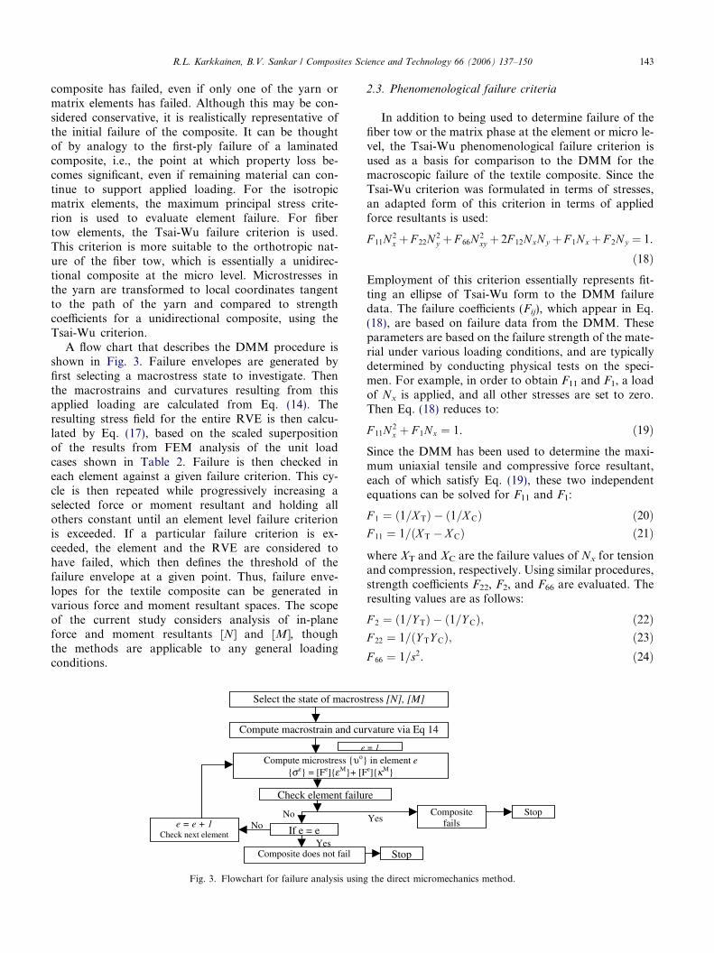
A flow chart that describes the DMM procedure isshown in Fig. 3. Failure envelopes are generated byfirst selecting a macrostress state to investigate. Thenthe macrostrains and curvatures resulting from thisapplied loading are calculated from Eq. (14). Theresulting stress field for the entire RVE is then calcu-lated by Eq. (17), based on the scaled superpositionof the results from FEM analysis of the unit loadcases shown in Table 2. Failure is then checked ineach element against a given failure criterion. This cy-cle is then repeated while progressively increasing aselected force or moment resultant and holding allothers constant until an element level failure criterionis exceeded. If a particular failure criterion is ex-ceeded, the element and the RVE are considered tohave failed, which then defines the threshold of thefailure envelope at a given point. Thus, failure enve-lopes for the textile composite can be generated invarious force and moment resultant spaces. The scopeof the current study considers analysis of in-planeforce and moment resultants [N] and [M], thoughthe methods are applicable to any general loadingconditions.
e = e + 1 Check next element
Check element failu
e
Compute microstress {υο}{σe} = [Fe]{εM}+ [F
Compute macrostrain and cu
Select the state of macrost
NoNo
YesComposite does not fail
If e = e
Fig. 3. Flowchart for failure analysis using
2.3. Phenomenological failure criteria
In addition to being used to determine failure of thefiber tow or the matrix phase at the element or micro le-vel, the Tsai-Wu phenomenological failure criterion isused as a basis for comparison to the DMM for themacroscopic failure of the textile composite. Since theTsai-Wu criterion was formulated in terms of stresses,an adapted form of this criterion in terms of appliedforce resultants is used:
F 11N 2x þ F 22N 2
y þ F 66N 2xy þ 2F 12NxNy þ F 1Nx þ F 2Ny ¼ 1.
ð18ÞEmployment of this criterion essentially represents fit-ting an ellipse of Tsai-Wu form to the DMM failuredata. The failure coefficients (Fij), which appear in Eq.(18), are based on failure data from the DMM. Theseparameters are based on the failure strength of the mate-rial under various loading conditions, and are typicallydetermined by conducting physical tests on the speci-men. For example, in order to obtain F11 and F1, a loadof Nx is applied, and all other stresses are set to zero.Then Eq. (18) reduces to:
F 11N 2x þ F 1Nx ¼ 1. ð19Þ
Since the DMM has been used to determine the maxi-mum uniaxial tensile and compressive force resultant,each of which satisfy Eq. (19), these two independentequations can be solved for F11 and F1:
F 1 ¼ ð1=X TÞ � ð1=XCÞ ð20ÞF 11 ¼ 1=ðX T � XCÞ ð21Þ
where XT and XC are the failure values of Nx for tensionand compression, respectively. Using similar procedures,strength coefficients F22, F2, and F66 are evaluated. Theresulting values are as follows:
F 2 ¼ ð1=Y TÞ � ð1=Y CÞ; ð22ÞF 22 ¼ 1=ðY TY CÞ; ð23ÞF 66 ¼ 1=s2. ð24Þ
Stop
StopCompositefails
re
= 1
in element ee]{κM}
rvature via Eq 14
ress [N], [M]
Yes
the direct micromechanics method.
144 R.L. Karkkainen, B.V. Sankar / Composites Science and Technology 66 (2006) 137–150
In the above equations Y and S are the strengths interms of the force resultants Ny and Nxy, and C and T
denote compression and tension, respectively. In the lit-erature, there exist many proposed methods for deter-mining an appropriate F12. In this paper, thecoefficient F12 is determined by subjecting the unit-cellto a state of biaxial stress such that Nx = Ny whileNxy = 0, and then determining the maximum value ofapplied Nx = Ny = Nmax. The resulting coefficient takesthe following form:
F 12 ¼1
2N 2max
1� ðF 11 þ F 22ÞN 2max � ðF 1 þ F 2ÞNmax
� �.
ð25ÞPlease note that for Eqs. (18)–(25), strength values mustbe in terms of force resultants (N), as noted in thenomenclature. This is different from the textbook defini-tion of the Tsai-Wu failure theory, which is in terms ofstresses. Also note that, as will be discussed later, theTsai-Wu failure theory includes no provision for theincorporation of applied moment resultants into the pre-diction of failure.
The maximum stress theory is another failure theoryto which the results of the DMM may be compared.Simply stated, failure occurs when any single stress com-ponent exceeds an allowable level:
XC < Nx < X T;
Y C < Ny < Y T;
jNxy j < S.
ð26Þ
And similarly, the maximum strain failure theory statesthat failure occurs when any single mid-plane straincomponent exceeds an allowable level:
eC < ex0 < eT;
eC < ey0 < eT;
jcxy0j < eLT.
ð27Þ
For example, the limiting mid-plane strain in a givendirection is:
ei ¼Nmax=tEi
. ð28Þ
The bounds of the maximum strain theory failure enve-lope take the shape of a parallelogram whose sides aredefined by lines of the form:
Ny ¼ mxyNx þ ST. ð29Þ
As was mentioned regarding the Tsai-Wu failure theory,the maximum stress and maximum strain theories weredeveloped in terms of applied stresses, thus adaptedforms of these criteria in terms of applied force resul-tants are used. Again, currently there is no provisionfor the incorporation of applied moments into the pre-diction of failure.
3. Results
3.1. Stiffness properties
The fiber tow was assumed to have material proper-ties of a unidirectional composite (weave geometry is ta-ken into account in the finite element model), in this caseAS/3501 graphite–epoxy with the following materialproperties:
The constitutive matrices relating macroscopic forceand moment resultants to strains and curvatures werefound using the aforementioned procedures and arefound to be:
½A� ¼4.14 0.52 0
0.52 4.14 0
0 0 0.18
264
375� 106ðPa�mÞ ½B� � 0
½D� ¼7.70 2.53 0
2.53 7.70 0
0 0 1.35
264
375� 10�3ðPa�m3Þ
ð30Þ
The character of the constitutive matrices is analogousto an orthotropic stiffness matrix with identical elasticconstants in the material principal directions (also re-ferred to as a tetragonal stiffness matrix). Flexural stiff-ness values of the [D] matrix may seem slightly low, butit should be noted that the RVE under consideration isrelatively thin at 0.254 mm. Also note that although thezero terms in the above matrices were not identicallyzero, they were several orders of magnitude below com-parable matrix terms, and thus have been neglected withlittle or no effect on end results.
The above constitutive matrices have been calculateddirectly from the micromechanics model without anyassumptions on the deformation of the composite suchas plane sections remain plane, etc., as in traditionalplate theories. The results are quite different from com-monly employed approximations. From classical lami-nate theory, a plane stiffness matrix is calculated fromhomogenized continuum stiffness properties (i.e., E, G,and m). The flexural stiffness matrix [D] is then calculatedfrom this homogenized stiffness and the thickness of thetextile RVE. By comparison to the direct micromechan-ics results of the DMM, these methods will misrepresentflexural stiffness values D11, D12, and D66 by as much asfactors of 2.9, 1.1, and 0.7, respectively. The DMM re-sults imply that there is no consistent relation betweenin-plane and flexural properties, although the two prop-erties are related.
As a basis for comparison, the following stiffnessproperties are presented in Table 4, as calculated directlyfrom the [A] and [D] matrices above.
In-plane axial and shear stiffness values (E, G) are cal-culated directly from the [A] matrix. Compared to thebare properties of the constituent fiber tows (Table 3),
Table 4Stiffness properties for plain weave textile plate
In-plane properties Ex = Ey (GPa) Gxy (GPa) mxy16.0 0.71 0.13
Flexural properties Efx = Efy (GPa) Gfxy (GPa) mfxy5.0 0.88 0.33
Table 3Fiber tow and matrix material properties [33]
Material E1 (GPa) E2 (GPa) G12 (GPa) m12
AS/3501 graphite/epoxy(65% fiber volume)
138 9.0 6.9 0.30
3501 Matrix 3.5 3.5 1.3 0.35
R.L. Karkkainen, B.V. Sankar / Composites Science and Technology 66 (2006) 137–150 145
stiffness is lower by an order of magnitude. But it mustbe noted that the textile composite under considerationhere has on overall volume fraction of 25%, whereas thetow properties of Table 3 reflect the 65% volume frac-tion as seen within the tow itself. Flexural moduli pre-sented in Table 4 are calculated from the followingrelations:
Efx ¼�Mx
Iyyjx¼ 12
t3D11
; ð31Þ
Efy ¼12
t3D22
; ð32Þ
Gfxy ¼12
t3D66
; ð33Þ
mfxy ¼D12
D11
. ð34Þ
Flexural moduli are material-dependent properties, butare strongly geometry-dependent as well. Similarly towhat is seen for the in-plane stiffness, the flexural stiff-ness is shown to be much lower than the constituenttow properties, for the relatively thin plate under consid-eration here. The bending properties are strongly influ-enced by the plate thickness and the weave architecture.
3.2. Strength properties
Table 5 shows the textbook values for failurestrengths of the yarn and matrix materials. The sub-scripts ‘‘L’’ and ‘‘T’’ refer to the longitudinal and trans-verse directions, respectively. The superscripts ‘‘+’’ and‘‘�’’ refer to tensile and compressive strength. Thesewere used with the Tsai-Wu failure criterion to deter-mine failure of the yarn at the micro level within an ele-
Table 5Fiber tow and matrix failure strength properties (MPa) [33]
SðþÞL Sð�Þ
L SðþÞT Sð�Þ
T SLT
3501/Graphite tow 1448 1172 48.3 60 62.13501 Matrix 70 70 70 70 70
ment. Note that buckling or instability of the tows is notconsidered for compressive failure analysis. Though notconsidered in many textile failure models, its incorpora-tion could be significant given the undulation or wavi-ness of woven tows, and a consequent reduction inallowable compressive stress may be seen [20,21].
Fig. 4 shows a comparison of the DMM failure enve-lope for the plain weave graphite/3501 textile compositewith several common failure theories: the Tsai-Wu,maximum stress, and maximum strain failure theories.Failure envelopes are shown in the plane of biaxial forceresultants with no applied moment present. Since theDMM is used to define the macro level failure strength,all theories share the same uniaxial strengths and are fitto these points. For the most part, the maximum stresstheory is much more conservative than all other theo-ries. However, it is less conservative in Quadrants IIand IV, since this failure theory does not account forthe interaction of biaxial stresses. The maximum strainand Tsai-Wu failure theories compare more closely tothe DMM failure envelope, especially the latter.
For zero applied moment (Fig. 4), the DMM failureenvelope follows closely with the form of a Tsai-Wu fail-ure envelope. For the most part, the initial failure modeis transverse failure of the fiber tows. However, at theextremes of the major axis of the failure envelope, i.e.,the outer corners of quadrants I and III, the initial fail-ure mode transitions to failure of the matrix material.Thus, the DMM failure envelope is cut short at the ends(compared to the failure envelope that would exist if ma-trix failure were not considered) and is squared-off inthese regions and resembles the maximum failure stress(force resultant) criterion. The DMM envelope is moreconservative than the Tsai-Wu type criterion in quad-rant I, and slightly less conservative in quadrant III.Note that although failure of the bulk matrix may notbe considered mechanical failure in some cases, it repre-sents a failure initiation at which point property loss willbegin to occur. If needed, without any significant mod-ification, the DMM can be adapted to ignore matrixfailure and limit the definition of initial failure to thepoint at which tow failure is first detected.
Though failure loads are not generally reported interms of force and moment resultants, a translation ofthe failure envelope force resultant values to traditionalstress values shows that strength magnitudes are reason-able based upon comparison to literature and supplier-reported values for this material, geometry, and therelatively low fiber volume fraction (25%). Since the yarntakes much of the load, the matrix does not begin to failuntil a much higher load than its bare tensile strength.Although the strength value is a fraction of the puretow strength, the woven tow is not completely aligned inthe loading directions, i.e., some of the tow is curved intothe thickness direction, providing through-thickness rein-forcement. Furthermore, after initial transverse failure of
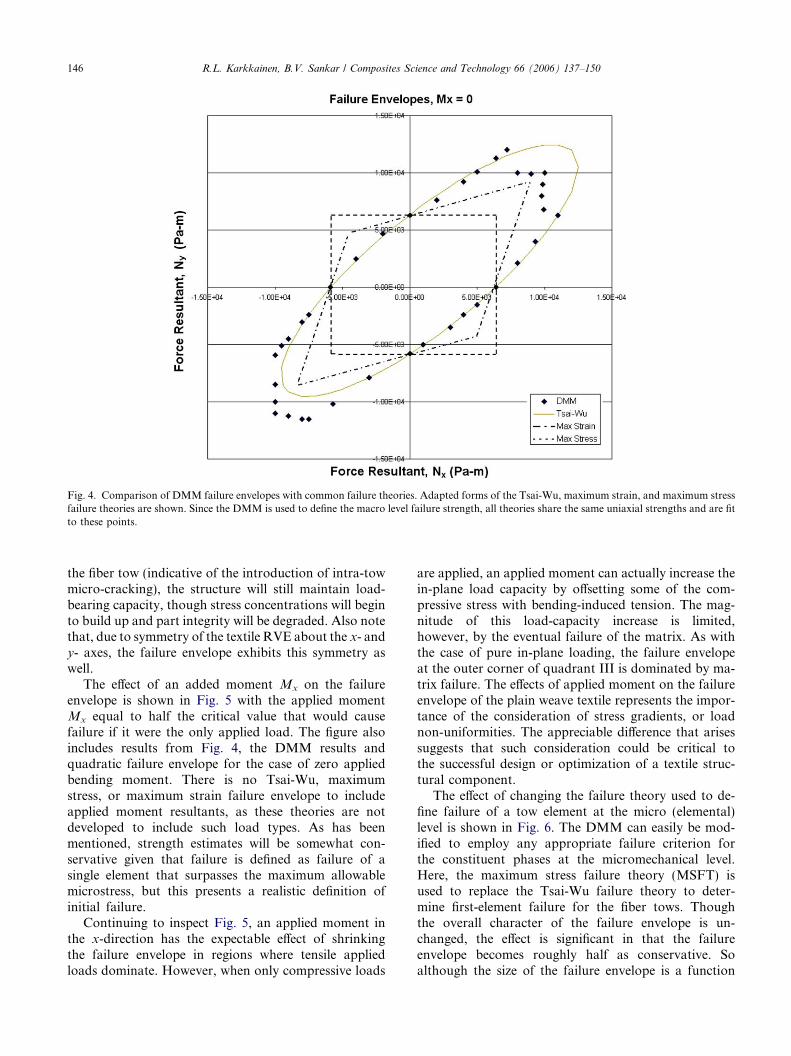
Fig. 4. Comparison of DMM failure envelopes with common failure theories. Adapted forms of the Tsai-Wu, maximum strain, and maximum stressfailure theories are shown. Since the DMM is used to define the macro level failure strength, all theories share the same uniaxial strengths and are fitto these points.
146 R.L. Karkkainen, B.V. Sankar / Composites Science and Technology 66 (2006) 137–150
the fiber tow (indicative of the introduction of intra-towmicro-cracking), the structure will still maintain load-bearing capacity, though stress concentrations will beginto build up and part integrity will be degraded. Also notethat, due to symmetry of the textile RVE about the x- andy- axes, the failure envelope exhibits this symmetry aswell.
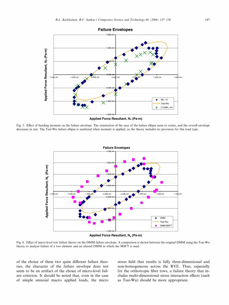
The effect of an added moment Mx on the failureenvelope is shown in Fig. 5 with the applied momentMx equal to half the critical value that would causefailure if it were the only applied load. The figure alsoincludes results from Fig. 4, the DMM results andquadratic failure envelope for the case of zero appliedbending moment. There is no Tsai-Wu, maximumstress, or maximum strain failure envelope to includeapplied moment resultants, as these theories are notdeveloped to include such load types. As has beenmentioned, strength estimates will be somewhat con-servative given that failure is defined as failure of asingle element that surpasses the maximum allowablemicrostress, but this presents a realistic definition ofinitial failure.
Continuing to inspect Fig. 5, an applied moment inthe x-direction has the expectable effect of shrinkingthe failure envelope in regions where tensile appliedloads dominate. However, when only compressive loads
are applied, an applied moment can actually increase thein-plane load capacity by offsetting some of the com-pressive stress with bending-induced tension. The mag-nitude of this load-capacity increase is limited,however, by the eventual failure of the matrix. As withthe case of pure in-plane loading, the failure envelopeat the outer corner of quadrant III is dominated by ma-trix failure. The effects of applied moment on the failureenvelope of the plain weave textile represents the impor-tance of the consideration of stress gradients, or loadnon-uniformities. The appreciable difference that arisessuggests that such consideration could be critical tothe successful design or optimization of a textile struc-tural component.
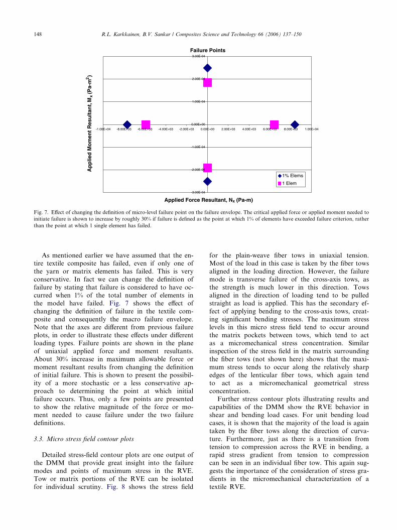
The effect of changing the failure theory used to de-fine failure of a tow element at the micro (elemental)level is shown in Fig. 6. The DMM can easily be mod-ified to employ any appropriate failure criterion forthe constituent phases at the micromechanical level.Here, the maximum stress failure theory (MSFT) isused to replace the Tsai-Wu failure theory to deter-mine first-element failure for the fiber tows. Thoughthe overall character of the failure envelope is un-changed, the effect is significant in that the failureenvelope becomes roughly half as conservative. Soalthough the size of the failure envelope is a function
Failure Envelopes
-1.50E+04
-1.00E+04
-5.00E+03
0.00E+00
5.00E+03
1.00E+04
1.50E+04
-1.50E+04 -1.00E+04 -5.00E+03 0.00E+00 5.00E+03 1.00E+04 1.50E+04
Applied Force Resultant, Nx (Pa-m)
Ap
plie
d F
orc
e R
esu
ltan
t, N
y (P
a-m
)
Mx = 0
Tsai-Wu
(1/2)Mx, crit
Fig. 5. Effect of bending moment on the failure envelope. The orientation of the axes of the failure ellipse seem to rotate, and the overall envelopedecreases in size. The Tsai-Wu failure ellipse is unaltered when moment is applied, as the theory includes no provision for this load type.
Failure Envelopes
-1.75E+04
-1.25E+04
-7.50E+03
-2.50E+03
2.50E+03
7.50E+03
1.25E+04
1.75E+04
-1.75E+04 -1.25E+04 -7.50E+03 -2.50E+03 2.50E+03 7.50E+03 1.25E+04 1.75E+04
Applied Force Resultant, Nx (Pa-m)
Ap
plie
d F
orc
e R
esu
ltan
t, N
y (
Pa-
m)
DMM
Tsai-Wu
DMM MSFT
Fig. 6. Effect of micro-level tow failure theory on the DMM failure envelope. A comparison is shown between the original DMM using the Tsai-Wutheory to analyze failure of a two element and an altered DMM in which the MSFT is used.
R.L. Karkkainen, B.V. Sankar / Composites Science and Technology 66 (2006) 137–150 147
of the choice of these two quite different failure theo-ries, the character of the failure envelope does notseem to be an artifact of the choice of micro-level fail-ure criterion. It should be noted that, even in the caseof simple uniaxial macro applied loads, the micro
stress field that results is fully three-dimensional andnon-homogeneous across the RVE. Thus, especiallyfor the orthotropic fiber tows, a failure theory that in-cludes multi-dimensional stress interaction effects (suchas Tsai-Wu) should be more appropriate.
Failure Points
-3.00E-04
-2.00E-04
-1.00E-04
0.00E+00
1.00E-04
2.00E-04
3.00E-04
-1.00E+04 -8.00E+03 -6.00E+03 -4.00E+03 -2.00E+03 0.00E+00 2.00E+03 4.00E+03 6.00E+03 8.00E+03 1.00E+04
Applied Force Resultant, Nx (Pa-m)
Ap
plie
d M
om
ent
Res
ult
ant,
Mx
(Pa-
m2)
1% Elems
1 Elem
Fig. 7. Effect of changing the definition of micro-level failure point on the failure envelope. The critical applied force or applied moment needed toinitiate failure is shown to increase by roughly 30% if failure is defined as the point at which 1% of elements have exceeded failure criterion, ratherthan the point at which 1 single element has failed.
148 R.L. Karkkainen, B.V. Sankar / Composites Science and Technology 66 (2006) 137–150
As mentioned earlier we have assumed that the en-tire textile composite has failed, even if only one ofthe yarn or matrix elements has failed. This is veryconservative. In fact we can change the definition offailure by stating that failure is considered to have oc-curred when 1% of the total number of elements inthe model have failed. Fig. 7 shows the effect ofchanging the definition of failure in the textile com-posite and consequently the macro failure envelope.Note that the axes are different from previous failureplots, in order to illustrate these effects under differentloading types. Failure points are shown in the planeof uniaxial applied force and moment resultants.About 30% increase in maximum allowable force ormoment resultant results from changing the definitionof initial failure. This is shown to present the possibil-ity of a more stochastic or a less conservative ap-proach to determining the point at which initialfailure occurs. Thus, only a few points are presentedto show the relative magnitude of the force or mo-ment needed to cause failure under the two failuredefinitions.
3.3. Micro stress field contour plots
Detailed stress-field contour plots are one output ofthe DMM that provide great insight into the failuremodes and points of maximum stress in the RVE.Tow or matrix portions of the RVE can be isolatedfor individual scrutiny. Fig. 8 shows the stress field
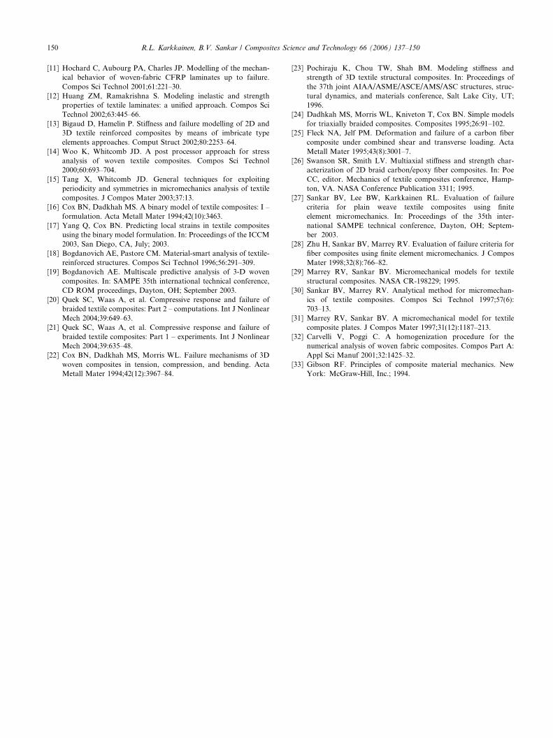
for the plain-weave fiber tows in uniaxial tension.Most of the load in this case is taken by the fiber towsaligned in the loading direction. However, the failuremode is transverse failure of the cross-axis tows, asthe strength is much lower in this direction. Towsaligned in the direction of loading tend to be pulledstraight as load is applied. This has the secondary ef-fect of applying bending to the cross-axis tows, creat-ing significant bending stresses. The maximum stresslevels in this micro stress field tend to occur aroundthe matrix pockets between tows, which tend to actas a micromechanical stress concentration. Similarinspection of the stress field in the matrix surroundingthe fiber tows (not shown here) shows that the maxi-mum stress tends to occur along the relatively sharpedges of the lenticular fiber tows, which again tendto act as a micromechanical geometrical stressconcentration.
Further stress contour plots illustrating results andcapabilities of the DMM show the RVE behavior inshear and bending load cases. For unit bending loadcases, it is shown that the majority of the load is againtaken by the fiber tows along the direction of curva-ture. Furthermore, just as there is a transition fromtension to compression across the RVE in bending, arapid stress gradient from tension to compressioncan be seen in an individual fiber tow. This again sug-gests the importance of the consideration of stress gra-dients in the micromechanical characterization of atextile RVE.
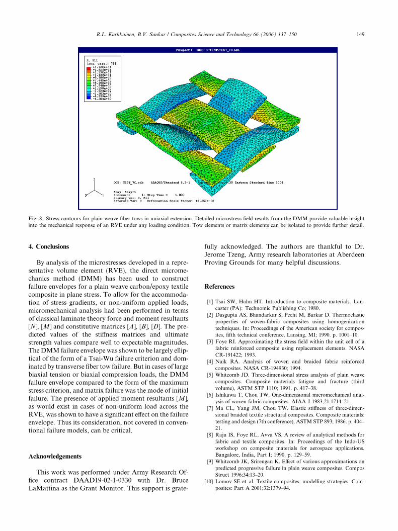
Fig. 8. Stress contours for plain-weave fiber tows in uniaxial extension. Detailed microstress field results from the DMM provide valuable insightinto the mechanical response of an RVE under any loading condition. Tow elements or matrix elements can be isolated to provide further detail.
R.L. Karkkainen, B.V. Sankar / Composites Science and Technology 66 (2006) 137–150 149
4. Conclusions
By analysis of the microstresses developed in a repre-sentative volume element (RVE), the direct microme-chanics method (DMM) has been used to constructfailure envelopes for a plain weave carbon/epoxy textilecomposite in plane stress. To allow for the accommoda-tion of stress gradients, or non-uniform applied loads,micromechanical analysis had been performed in termsof classical laminate theory force and moment resultants[N], [M] and constitutive matrices [A], [B], [D]. The pre-dicted values of the stiffness matrices and ultimatestrength values compare well to expectable magnitudes.The DMM failure envelope was shown to be largely ellip-tical of the form of a Tsai-Wu failure criterion and dom-inated by transverse fiber tow failure. But in cases of largebiaxial tension or biaxial compression loads, the DMMfailure envelope compared to the form of the maximumstress criterion, and matrix failure was the mode of initialfailure. The presence of applied moment resultants [M],as would exist in cases of non-uniform load across theRVE, was shown to have a significant effect on the failureenvelope. Thus its consideration, not covered in conven-tional failure models, can be critical.
Acknowledgements
This work was performed under Army Research Of-fice contract DAAD19-02-1-0330 with Dr. BruceLaMattina as the Grant Monitor. This support is grate-
fully acknowledged. The authors are thankful to Dr.Jerome Tzeng, Army research laboratories at AberdeenProving Grounds for many helpful discussions.
References
[1] Tsai SW, Hahn HT. Introduction to composite materials. Lan-caster (PA): Technomic Publishing Co; 1980.
[2] Dasgupta AS, Bhandarkar S, Pecht M, Barkar D. Thermoelasticproperties of woven-fabric composites using homogenizationtechniques. In: Proceedings of the American society for compos-ites, fifth technical conference, Lansing, MI; 1990. p. 1001–10.
[3] Foye RI. Approximating the stress field within the unit cell of afabric reinforced composite using replacement elements. NASACR-191422; 1993.
[4] Naik RA. Analysis of woven and braided fabric reinforcedcomposites. NASA CR-194930; 1994.
[5] Whitcomb JD. Three-dimensional stress analysis of plain weavecomposites. Composite materials fatigue and fracture (thirdvolume), ASTM STP 1110; 1991. p. 417–38.
[6] Ishikawa T, Chou TW. One-dimensional micromechanical anal-ysis of woven fabric composites. AIAA J 1983;21:1714–21.
[7] Ma CL, Yang JM, Chou TW. Elastic stiffness of three-dimen-sional braided textile structural composites. Composite materials:testing and design (7th conference), ASTM STP 893; 1986. p. 404–21.
[8] Raju IS, Foye RL, Avva VS. A review of analytical methods forfabric and textile composites. In: Proceedings of the Indo-USworkshop on composite materials for aerospace applications,Bangalore, India, Part I; 1990. p. 129–59.
[9] Whitcomb JK, Srirengan K. Effect of various approximations onpredicted progressive failure in plain weave composites. ComposStruct 1996;34:13–20.
[10] Lomov SE et al. Textile composites: modelling strategies. Com-posites: Part A 2001;32:1379–94.
150 R.L. Karkkainen, B.V. Sankar / Composites Science and Technology 66 (2006) 137–150
[11] Hochard C, Aubourg PA, Charles JP. Modelling of the mechan-ical behavior of woven-fabric CFRP laminates up to failure.Compos Sci Technol 2001;61:221–30.
[12] Huang ZM, Ramakrishna S. Modeling inelastic and strengthproperties of textile laminates: a unified approach. Compos SciTechnol 2002;63:445–66.
[13] Bigaud D, Hamelin P. Stiffness and failure modelling of 2D and3D textile reinforced composites by means of imbricate typeelements approaches. Comput Struct 2002;80:2253–64.
[14] Woo K, Whitcomb JD. A post processor approach for stressanalysis of woven textile composites. Compos Sci Technol2000;60:693–704.
[15] Tang X, Whitcomb JD. General techniques for exploitingperiodicity and symmetries in micromechanics analysis of textilecomposites. J Compos Mater 2003;37:13.
[16] Cox BN, Dadkhah MS. A binary model of textile composites: I –formulation. Acta Metall Mater 1994;42(10):3463.
[17] Yang Q, Cox BN. Predicting local strains in textile compositesusing the binary model formulation. In: Proceedings of the ICCM2003, San Diego, CA, July; 2003.
[18] Bogdanovich AE, Pastore CM. Material-smart analysis of textile-reinforced structures. Compos Sci Technol 1996;56:291–309.
[19] Bogdanovich AE. Multiscale predictive analysis of 3-D wovencomposites. In: SAMPE 35th international technical conference,CD ROM proceedings, Dayton, OH; September 2003.
[20] Quek SC, Waas A, et al. Compressive response and failure ofbraided textile composites: Part 2 – computations. Int J NonlinearMech 2004;39:649–63.
[21] Quek SC, Waas A, et al. Compressive response and failure ofbraided textile composites: Part 1 – experiments. Int J NonlinearMech 2004;39:635–48.
[22] Cox BN, Dadkhah MS, Morris WL. Failure mechanisms of 3Dwoven composites in tension, compression, and bending. ActaMetall Mater 1994;42(12):3967–84.
[23] Pochiraju K, Chou TW, Shah BM. Modeling stiffness andstrength of 3D textile structural composites. In: Proceedings ofthe 37th joint AIAA/ASME/ASCE/AMS/ASC structures, struc-tural dynamics, and materials conference, Salt Lake City, UT;1996.
[24] Dadhkah MS, Morris WL, Kniveton T, Cox BN. Simple modelsfor triaxially braided composites. Composites 1995;26:91–102.
[25] Fleck NA, Jelf PM. Deformation and failure of a carbon fibercomposite under combined shear and transverse loading. ActaMetall Mater 1995;43(8):3001–7.
[26] Swanson SR, Smith LV. Multiaxial stiffness and strength char-acterization of 2D braid carbon/epoxy fiber composites. In: PoeCC, editor. Mechanics of textile composites conference, Hamp-ton, VA. NASA Conference Publication 3311; 1995.
[27] Sankar BV, Lee BW, Karkkainen RL. Evaluation of failurecriteria for plain weave textile composites using finiteelement micromechanics. In: Proceedings of the 35th inter-national SAMPE technical conference, Dayton, OH; Septem-ber 2003.
[28] Zhu H, Sankar BV, Marrey RV. Evaluation of failure criteria forfiber composites using finite element micromechanics. J ComposMater 1998;32(8):766–82.
[29] Marrey RV, Sankar BV. Micromechanical models for textilestructural composites. NASA CR-198229; 1995.
[30] Sankar BV, Marrey RV. Analytical method for micromechan-ics of textile composites. Compos Sci Technol 1997;57(6):703–13.
[31] Marrey RV, Sankar BV. A micromechanical model for textilecomposite plates. J Compos Mater 1997;31(12):1187–213.
[32] Carvelli V, Poggi C. A homogenization procedure for thenumerical analysis of woven fabric composites. Compos Part A:Appl Sci Manuf 2001;32:1425–32.
[33] Gibson RF. Principles of composite material mechanics. NewYork: McGraw-Hill, Inc.; 1994.