a diagrammatic formalisation of mof-based modelling languages
TRANSCRIPT
Formalisation of MOF-based Modelling Languages
A Diagrammatic Formalisation of MOF-BasedModelling Languages
Adrian Rutle1, Alessandro Rossini2, Yngve Lamo1, Uwe Wolter2
1Faculty of Engineering, Bergen University College, Norway
2Department of Informatics, University of Bergen, Norway
30 June 2009TOOLS Europe, Zurich
Formalisation of MOF-based Modelling Languages
Introduction and Motivation
Outline
1 Introduction and MotivationMotivating Example
2 Diagram Predicate Framework (DPF)SyntaxSemantics
3 MOF-based Modelling LanguagesThe 4-Layered Modelling Architecture
4 Case-Study: Formalisation of EMF
5 Summary and Future Work
Formalisation of MOF-based Modelling Languages
Introduction and Motivation
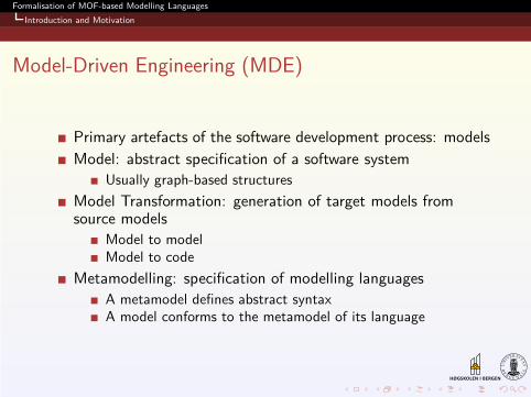
Model-Driven Engineering (MDE)
Primary artefacts of the software development process: models
Model: abstract specification of a software system
Usually graph-based structures
Model Transformation: generation of target models fromsource models
Model to modelModel to code
Metamodelling: specification of modelling languages
A metamodel defines abstract syntaxA model conforms to the metamodel of its language
Formalisation of MOF-based Modelling Languages
Introduction and Motivation
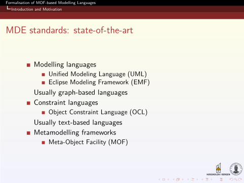
MDE standards: state-of-the-art
Modelling languages
Unified Modeling Language (UML)Eclipse Modeling Framework (EMF)
Usually graph-based languages
Constraint languages
Object Constraint Language (OCL)
Usually text-based languages
Metamodelling frameworks
Meta-Object Facility (MOF)
Formalisation of MOF-based Modelling Languages
Introduction and Motivation
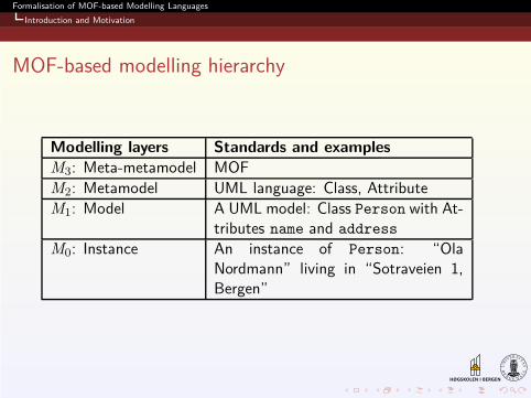
MOF-based modelling hierarchy
Modelling layers Standards and examples
M3: Meta-metamodel MOF
M2: Metamodel UML language: Class, Attribute
M1: Model A UML model: Class Person with At-tributes name and address
M0: Instance An instance of Person: “OlaNordmann” living in “Sotraveien 1,Bergen”
Formalisation of MOF-based Modelling Languages
Introduction and Motivation
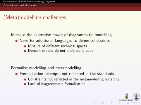
(Meta)modelling challenges
Increase the expressive power of diagrammatic modelling:
Need for additional languages to define constraints
Mixture of different technical spacesDomain experts do not understand code
Formalise modelling and metamodelling:
Formalisation attempts not reflected in the standards
Constraints not reflected in the metamodelling hierarchyLack of diagrammatic formalisation
Formalisation of MOF-based Modelling Languages
Introduction and Motivation
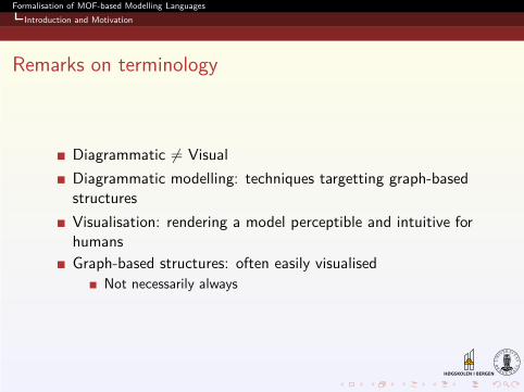
Remarks on terminology
Diagrammatic 6= Visual
Diagrammatic modelling: techniques targetting graph-basedstructures
Visualisation: rendering a model perceptible and intuitive forhumans
Graph-based structures: often easily visualised
Not necessarily always
Formalisation of MOF-based Modelling Languages
Introduction and Motivation
Motivating Example
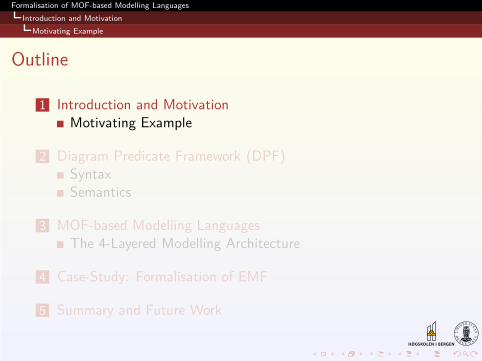
Outline
1 Introduction and MotivationMotivating Example
2 Diagram Predicate Framework (DPF)SyntaxSemantics
3 MOF-based Modelling LanguagesThe 4-Layered Modelling Architecture
4 Case-Study: Formalisation of EMF
5 Summary and Future Work
Formalisation of MOF-based Modelling Languages
Introduction and Motivation
Motivating Example
Motivating example
Requirements
1 An employee must work for at least one department.
2 A department may have none or many employees.
Formalisation of MOF-based Modelling Languages
Introduction and Motivation
Motivating Example
Motivating example
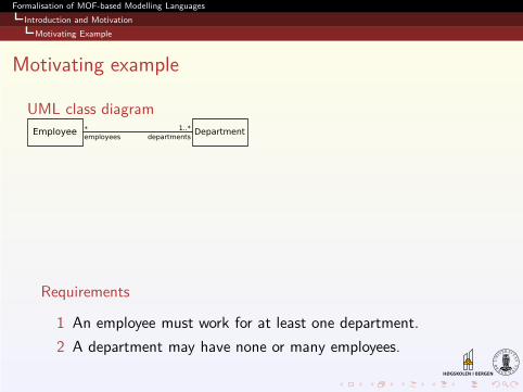
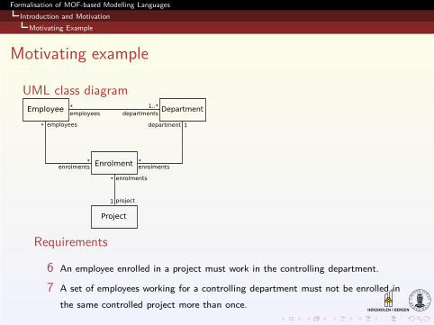
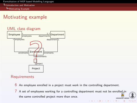
UML class diagram
Requirements
1 An employee must work for at least one department.
2 A department may have none or many employees.
Formalisation of MOF-based Modelling Languages
Introduction and Motivation
Motivating Example
Motivating example
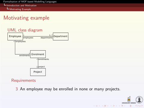
UML class diagram
Requirements
3 An employee may be enrolled in none or many projects.
Formalisation of MOF-based Modelling Languages
Introduction and Motivation
Motivating Example
Motivating example
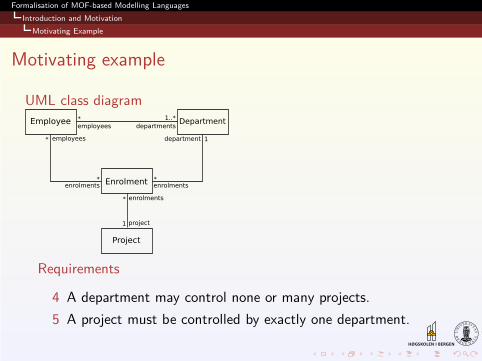
UML class diagram
Requirements
4 A department may control none or many projects.
5 A project must be controlled by exactly one department.
Formalisation of MOF-based Modelling Languages
Introduction and Motivation
Motivating Example
Motivating example
UML class diagram
Requirements
6 An employee enrolled in a project must work in the controlling department.
7 A set of employees working for a controlling department must not be enrolled in
the same controlled project more than once.
Formalisation of MOF-based Modelling Languages
Introduction and Motivation
Motivating Example
Motivating example
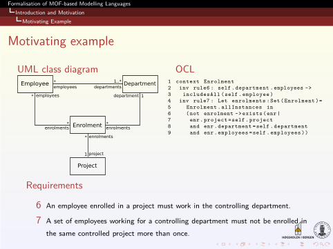
UML class diagram OCL1 context Enrolment
2 inv rule6 : self . department .employees ->
3 includesAll (self . employee )
4 inv rule7 : Let enrolments :Set ( Enrolment )=
5 Enrolment . allInstances in
6 ( not enrolment -> exists (enr |
7 enr. project =self . project
8 and enr .department =self . department
9 and enr .employees =self . employees ))
Requirements
6 An employee enrolled in a project must work in the controlling department.
7 A set of employees working for a controlling department must not be enrolled in
the same controlled project more than once.
Formalisation of MOF-based Modelling Languages
Introduction and Motivation
Motivating Example
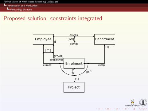
Proposed solution: constraints integrated
Formalisation of MOF-based Modelling Languages
Introduction and Motivation
Motivating Example
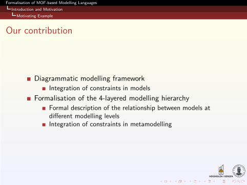
Our contribution
Diagrammatic modelling framework
Integration of constraints in models
Formalisation of the 4-layered modelling hierarchy
Formal description of the relationship between models atdifferent modelling levelsIntegration of constraints in metamodelling
Formalisation of MOF-based Modelling Languages
Diagram Predicate Framework (DPF)
Outline
1 Introduction and MotivationMotivating Example
2 Diagram Predicate Framework (DPF)SyntaxSemantics
3 MOF-based Modelling LanguagesThe 4-Layered Modelling Architecture
4 Case-Study: Formalisation of EMF
5 Summary and Future Work
Formalisation of MOF-based Modelling Languages
Diagram Predicate Framework (DPF)
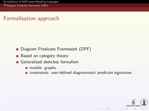
Formalisation approach
Diagram Predicate Framework (DPF)
Based on category theory
Generalized sketches formalism
models: graphsconstraints: user-defined diagrammatic predicate signatures
Formalisation of MOF-based Modelling Languages
Diagram Predicate Framework (DPF)
Syntax
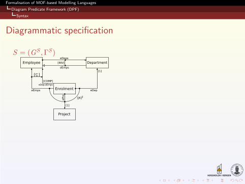
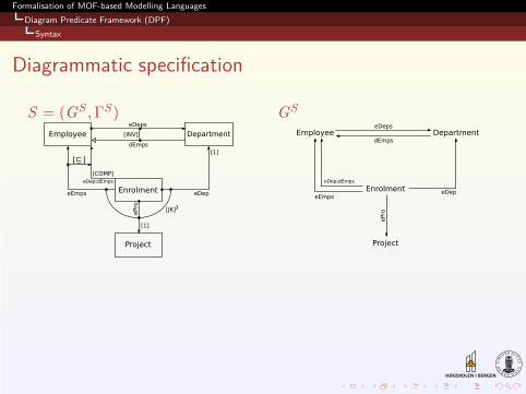
Diagrammatic specification
S = (GS ,ΓS)
Formalisation of MOF-based Modelling Languages
Diagram Predicate Framework (DPF)
Syntax
Diagrammatic specification
S = (GS ,ΓS) GS
Formalisation of MOF-based Modelling Languages
Diagram Predicate Framework (DPF)
Syntax
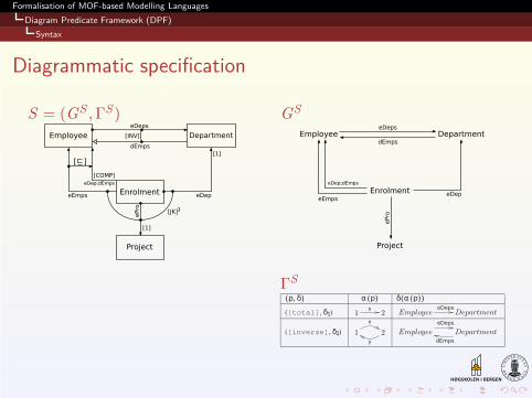
Diagrammatic specification
S = (GS ,ΓS) GS
ΓS
Formalisation of MOF-based Modelling Languages
Diagram Predicate Framework (DPF)
Syntax
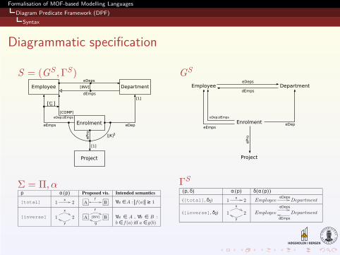
Diagrammatic specification
S = (GS ,ΓS)
Σ = Π, α
GS
ΓS
Formalisation of MOF-based Modelling Languages
Diagram Predicate Framework (DPF)
Syntax
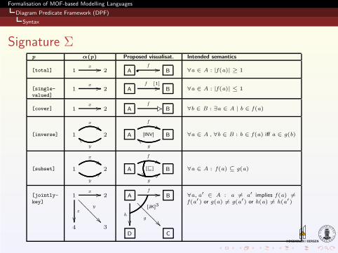
Signature Σ
p α(p) Proposed visualisat. Intended semantics
[total] 1x // 2 A •
f // B ∀a ∈ A : |f (a)| ≥ 1
[single-
valued]1
x // 2 Af [1]// B ∀a ∈ A : |f (a)| ≤ 1
[cover] 1x // 2 A
f� ,2 B ∀b ∈ B : ∃a ∈ A | b ∈ f (a)
[inverse] 1
x
##2
y
cc A
f
''[INV] B
g
gg ∀a ∈ A , ∀b ∈ B : b ∈ f (a) iff a ∈ g(b)
[subset] 1
x
##
y
;; 2 A
f
''
g
77[⊑]
��B ∀a ∈ A : f (a) ⊆ g(a)
[jointly-
key]1
x //y
��??
?
?
?
?
?
z
��
2
4 3
Af //
g
��??
?
?
?
?
?
h
��
[JK]3
B
D C
∀a, a′ ∈ A : a 6= a′ implies f (a) 6=f (a′) or g(a) 6= g(a′) or h(a) 6= h(a′)
Formalisation of MOF-based Modelling Languages
Diagram Predicate Framework (DPF)
Semantics
Outline
1 Introduction and MotivationMotivating Example
2 Diagram Predicate Framework (DPF)SyntaxSemantics
3 MOF-based Modelling LanguagesThe 4-Layered Modelling Architecture
4 Case-Study: Formalisation of EMF
5 Summary and Future Work
Formalisation of MOF-based Modelling Languages
Diagram Predicate Framework (DPF)
Semantics
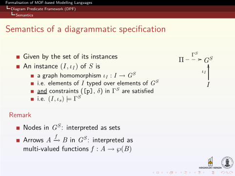
Semantics of a diagrammatic specification
Given by the set of its instances
An instance (I , ιI ) of S is
a graph homomorphism ιI : I → GS
i.e. elements of I typed over elements of GS
and constraints ([p], δ) in ΓS are satisfiedi.e. (I , ιs) |= ΓS
Remark
Nodes in GS : interpreted as sets
Arrows Af−→ B in GS : interpreted as
multi-valued functions f : A→ ℘(B)
ΠΓ
S
//___ GS
I
ιI
OO
Formalisation of MOF-based Modelling Languages
MOF-based Modelling Languages
Outline
1 Introduction and MotivationMotivating Example
2 Diagram Predicate Framework (DPF)SyntaxSemantics
3 MOF-based Modelling LanguagesThe 4-Layered Modelling Architecture
4 Case-Study: Formalisation of EMF
5 Summary and Future Work
Formalisation of MOF-based Modelling Languages
MOF-based Modelling Languages
The 4-Layered Modelling Architecture
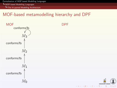
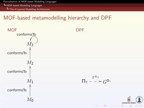
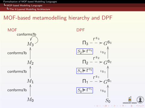
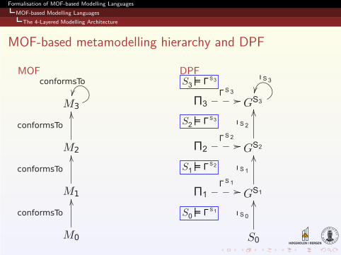
MOF-based metamodelling hierarchy and DPF
MOF DPF
Formalisation of MOF-based Modelling Languages
MOF-based Modelling Languages
The 4-Layered Modelling Architecture
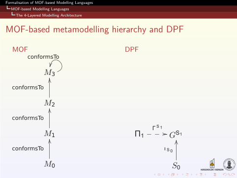
MOF-based metamodelling hierarchy and DPF
MOF DPF
Formalisation of MOF-based Modelling Languages
MOF-based Modelling Languages
The 4-Layered Modelling Architecture
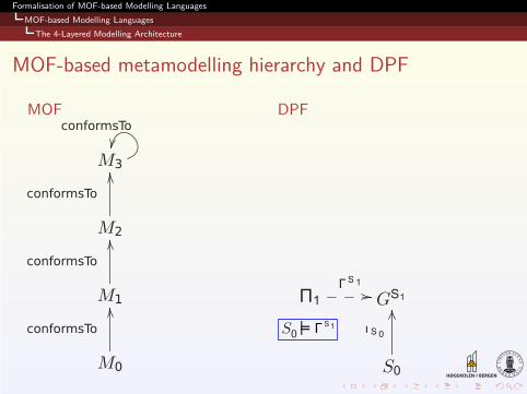
MOF-based metamodelling hierarchy and DPF
MOF DPF
Formalisation of MOF-based Modelling Languages
MOF-based Modelling Languages
The 4-Layered Modelling Architecture
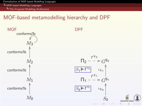
MOF-based metamodelling hierarchy and DPF
MOF DPF
Formalisation of MOF-based Modelling Languages
MOF-based Modelling Languages
The 4-Layered Modelling Architecture
MOF-based metamodelling hierarchy and DPF
MOF DPF
Formalisation of MOF-based Modelling Languages
MOF-based Modelling Languages
The 4-Layered Modelling Architecture
MOF-based metamodelling hierarchy and DPF
MOF DPF
Formalisation of MOF-based Modelling Languages
MOF-based Modelling Languages
The 4-Layered Modelling Architecture
MOF-based metamodelling hierarchy and DPF
MOF DPF
Formalisation of MOF-based Modelling Languages
Case-Study: Formalisation of EMF
Outline
1 Introduction and MotivationMotivating Example
2 Diagram Predicate Framework (DPF)SyntaxSemantics
3 MOF-based Modelling LanguagesThe 4-Layered Modelling Architecture
4 Case-Study: Formalisation of EMF
5 Summary and Future Work
Formalisation of MOF-based Modelling Languages
Case-Study: Formalisation of EMF
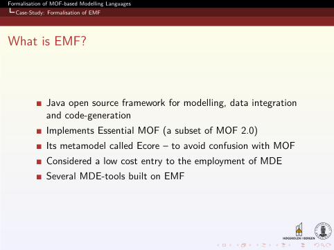
What is EMF?
Java open source framework for modelling, data integrationand code-generation
Implements Essential MOF (a subset of MOF 2.0)
Its metamodel called Ecore – to avoid confusion with MOF
Considered a low cost entry to the employment of MDE
Several MDE-tools built on EMF
Formalisation of MOF-based Modelling Languages
Case-Study: Formalisation of EMF
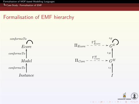
Formalisation of EMF hierarchy
Ecore
conformsTo
��
Model
conformsTo
OO
Instance
conformsTo
OO
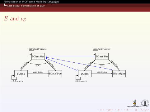
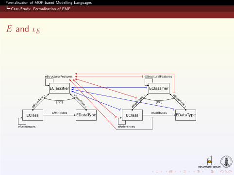
ΠEcore
ΓEEcore //______ GE
ιE
��
ΠCore
ΓMCore //______ GM
ιM
OO
I
ιI
OO
Formalisation of MOF-based Modelling Languages
Case-Study: Formalisation of EMF
E and ιE
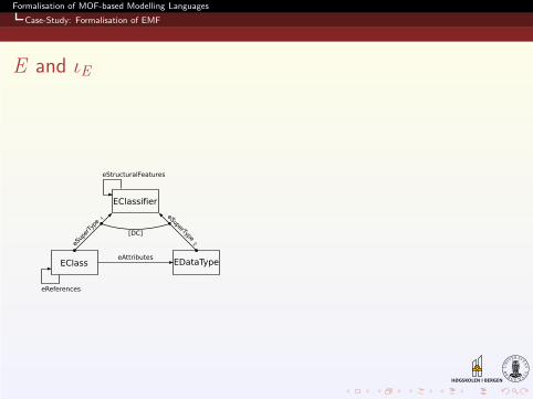
Formalisation of MOF-based Modelling Languages
Case-Study: Formalisation of EMF
E and ιE
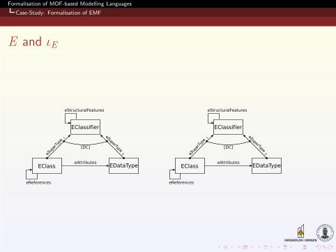
Formalisation of MOF-based Modelling Languages
Case-Study: Formalisation of EMF
E and ιE
Formalisation of MOF-based Modelling Languages
Case-Study: Formalisation of EMF
E and ιE
Formalisation of MOF-based Modelling Languages
Case-Study: Formalisation of EMF
E and ιE
Formalisation of MOF-based Modelling Languages
Summary and Future Work
Outline
1 Introduction and MotivationMotivating Example
2 Diagram Predicate Framework (DPF)SyntaxSemantics
3 MOF-based Modelling LanguagesThe 4-Layered Modelling Architecture
4 Case-Study: Formalisation of EMF
5 Summary and Future Work
Formalisation of MOF-based Modelling Languages
Summary and Future Work
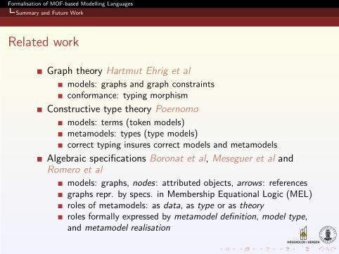
Related work
Graph theory Hartmut Ehrig et al
models: graphs and graph constraintsconformance: typing morphism
Constructive type theory Poernomo
models: terms (token models)metamodels: types (type models)correct typing insures correct models and metamodels
Algebraic specifications Boronat et al, Meseguer et al andRomero et al
models: graphs, nodes : attributed objects, arrows : referencesgraphs repr. by specs. in Membership Equational Logic (MEL)roles of metamodels: as data, as type or as theory
roles formally expressed by metamodel definition, model type,and metamodel realisation
Formalisation of MOF-based Modelling Languages
Summary and Future Work
Summary
DPF as a formal diagrammatic specification framework
Integration of constraints in modelling
Presentation of a generic and flexible scheme for theformalisation of metamodelling
Application of the scheme to MOF modelling hierarchy
Integration of constraints in metamodelling
Formalisation of EMF hierarchy as a case-study
Formalisation of MOF-based Modelling Languages
Summary and Future Work
Applications of DPF
Formalisation of UML, ER, Relational Data Models
Formalisation of copy-modify-merge approach to versioncontrol
Formalisation of constraint-aware model transformation rules
Formalisation of MOF-based Modelling Languages
Summary and Future Work
Future work
Transformation of UML/OCL to DPF
Dependency between predicates
Prototype tool
Comparison to Epsilon, Fujaba etc
Real-size case study: noark (Norwegian Archive standard)
Formalisation of MOF-based Modelling Languages
Summary and Future Work
Thank you!
Questions?
Formalisation of MOF-based Modelling Languages
Summary and Future Work
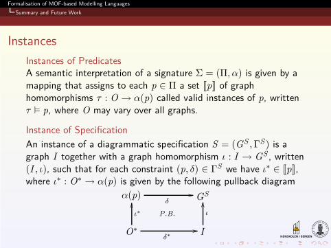
Instances
Instances of PredicatesA semantic interpretation of a signature Σ = (Π, α) is given by amapping that assigns to each p ∈ Π a set [[p]] of graphhomomorphisms τ : O → α(p) called valid instances of p, writtenτ � p, where O may vary over all graphs.
Instance of Specification
An instance of a diagrammatic specification S = (GS ,ΓS) is agraph I together with a graph homomorphism ι : I → GS , written(I , ι), such that for each constraint (p, δ) ∈ ΓS we have ι∗ ∈ [[p]],where ι∗ : O∗ → α(p) is given by the following pullback diagram
α(p)δ
// GS
O∗δ∗
//
ι∗
OO
P.B.
I
ι
OO
Formalisation of MOF-based Modelling Languages
Summary and Future Work
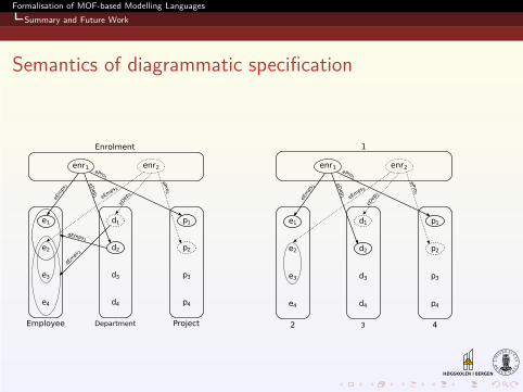
Semantics of diagrammatic specification
Formalisation of MOF-based Modelling Languages
Summary and Future Work
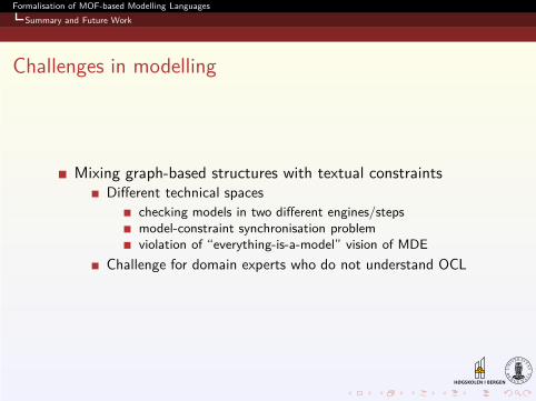
Challenges in modelling
Mixing graph-based structures with textual constraintsDifferent technical spaces
checking models in two different engines/stepsmodel-constraint synchronisation problemviolation of “everything-is-a-model” vision of MDE
Challenge for domain experts who do not understand OCL
Formalisation of MOF-based Modelling Languages
Summary and Future Work
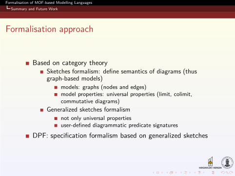
Formalisation approach
Based on category theorySketches formalism: define semantics of diagrams (thusgraph-based models)
models: graphs (nodes and edges)model properties: universal properties (limit, colimit,commutative diagrams)
Generalized sketches formalism
not only universal propertiesuser-defined diagrammatic predicate signatures
DPF: specification formalism based on generalized sketches