a diagnosing common rail diesel fuel systems · pdf filecommon rail diesel fuel systems common...
TRANSCRIPT

Anewcustomer walks intoyour shop with a vehiclethat has lost perfor-mance and has an inter-mittent stalling condi-tion. You begin the
process of collecting information fromthe customer, and during the conversa-tion he mentions that the vehicle is adiesel. Is your shop ready to work onpassenger car and/or light-duty dieselvehicles, or do you politely decline andsend the customer away?
The decision to avoid working ondiesel vehicles may have made goodbusiness sense in the past. But the situa-tion is changing. In 2013, there were 37models of diesel vehicles, the majoritybeing domestic light trucks and Euro-pean vehicles. In that same year, Chevylaunched the diesel Cruze and Jeep up-dated the Grand Cherokee with a new-er diesel engine. In 2014, as the Euro-pean models continue to expand,Dodge introduced the diesel version ofthe Ram 1500 and the Mazda6 willsoon have a diesel engine option.
By 2016, there will be more than 82different diesel models available, andsome of these will be common work ve-hicles like the Chevy Colorado and Nis-san Titan, along with some domesticpassenger car offerings. We know thistrend will continue, driven by the re-quirement to increase fuel economy,provide good vehicle performance and,with new clean diesel technology, meettougher tailpipe emissions standards.
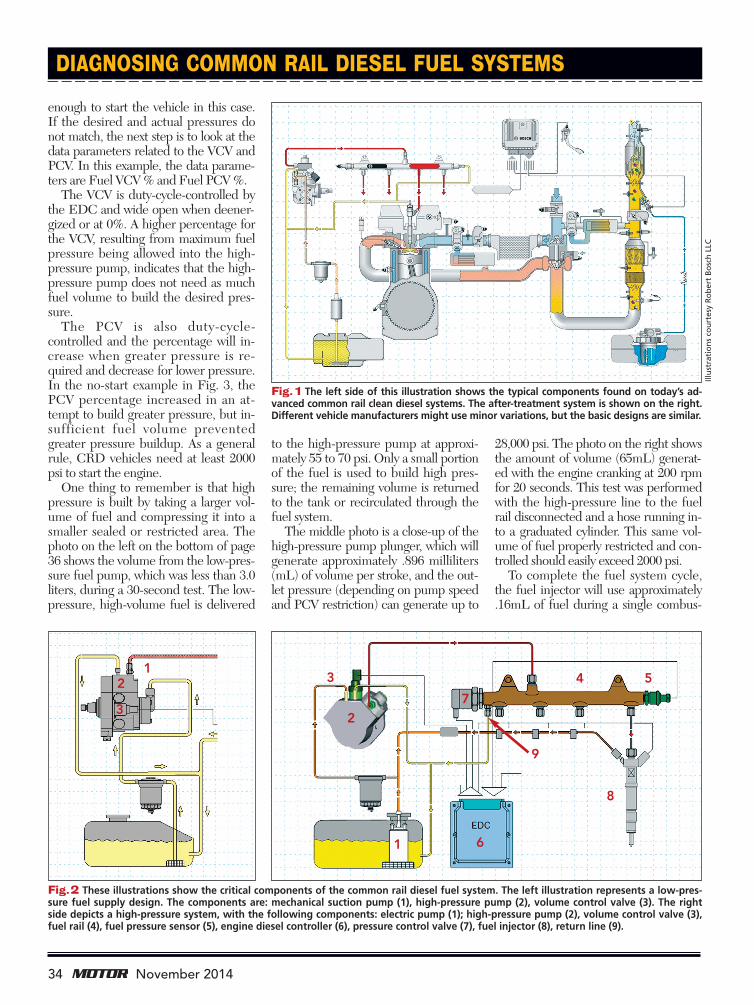
For those not working on diesel vehi-cles yet, here’s something to consider:Perhaps you’re already working on orpreparing to service gasoline direct injec-tion (GDI) vehicles. Well, the differ-ences between GDI and common raildiesel (CRD) systems are fairly small.Fig. 1 on page 34 shows a typical 4-cylin-der CRD engine system with the fuelsystem components on the left and theafter-treatment system on the right.What’s in between? If you follow the airinlet in the center of the image, you’ll seea mass airflow (MAF) sensor, followedby a turbocharger, intercooler, electroniccontrol throttle and exhaust gas recircula-tion (EGR) system, all of which are alsoused in a GDI system. In fact, for manyvehicle manufacturers, the MAF sensoris the same in both applications.
At a high level, what are the primarydifferences? Both GDI and CRD sys-tems use a high-pressure pump, but thepressures are very different—3000 psifor GDI and up to 28,000 psi for a CRDsystem. The next obvious difference isthat CRD systems use heat to ignite theair/fuel mixture, while GDI uses a sparkignition system to ignite the air/fuel mix-
ture. Both CRD and GDI vehicles needafter-treatment emissions systems, butthe CRD also needs to handle particu-late matter and higher NOX emissions.
Bottom line? With proper training,adding CRD service is not a stretch andcan offer additional revenue in the fu-ture. You can still make the decision tonot work on large trucks or Sprinter
32 November 2014
DIAGNOSINGCOMMON RAILDIESEL FUEL
SYSTEMS
DIAGNOSINGCOMMON RAILDIESEL FUEL
SYSTEMSBY BOB PATTENGALE
Fear of the unknown or a prior badexperience may be causing you tosteer clear of common rail dieselservice. Learning how to diagnose
these systems should helpovercome your reservations.
BY BOB PATTENGALE
Fear of the unknown or a prior badexperience may be causing you tosteer clear of common rail dieselservice. Learning how to diagnose
these systems should helpovercome your reservations.
Pg_EDIT_Diesel:Pg_EDIT_ 10/17/14 8:36 AM Page 1

vans, but servicing a Chevy Cruze orMazda6 diesel, for example, should fitright into your business.
If you can get past the smell of dieselfuel, I believe the next major hurdles formost technicians are to stop being intim-idated by the pressures in the fuel railand to learn how to properly diagnoseand test the high-pressure fuel system.
This article will help you understand thecritical components in the common raildiesel fuel system and tell you what youneed to know to diagnose it successfully.
Fig. 2 on page 34 shows a typicalCRD fuel system layout. The illustra-tion on the left represents a low-pres-sure fuel supply design with a suctionpump that’s attached to the back of the
pump housing and driven by the high-pressure pump. The illustration on theright shows that the low-pressure fuel tothe high-pressure pump is supplied byan electric pump in the fuel tank or onthe frame rail. The remaining compo-nents shown on the right are fairly com-mon to both designs and will be cov-ered here one by one.
General fuel system operation is fair-ly simple: The low-pressure pump (1)supplies fuel to the high-pressure pump(2). The volume control valve (VCV) ormetering solenoid (3) controls theamount of fuel entering into the high-pressure pump. As the engine rotates,fuel is compressed inside the high-pres-sure pump and transferred to the fuelrail (4). The fuel pressure sensor (FPS)(5) provides actual rail pressure feed-back to the engine diesel controller(EDC) (6), which uses a combination ofthe VCV and the pressure control valve(PCV) (7) to set the desired rail pres-sures for various operating ranges.
Diagnosing a CRD system is also fair-ly simple. The starting point is getting ascan tool connected and basically moni-toring two data parameters—actual fuelpressure and desired fuel pressure. Fig. 3(left side) on page 36 shows scan tool datafrom a 2011 Ford F-250 6.7L engine. Inthis example, data parameters FRP A (P)at 5634 psi and FRP Des (P) at 5235 psineed to bemonitored. On a normally op-erating engine the actual and desiredpressures should be close to one another.In this case, the data was captured at idlespeed, but depending on the driveabilityconcern, you’d want to take the vehiclefor a drive and monitor in all operatingranges. Specifically, a high-load road testwill show what happens when the great-est amount of fuel is required.
The quality and condition of the fuelare critical on a diesel engine. If the ac-tual and desired pressures match in alloperating ranges, the next steps are totake a sample of the fuel to look for ob-vious contamination and perform a spe-cific gravity test.
The data on the right side of Fig. 3was captured from the same vehicle, butwith a faulty low-pressure fuel pump. Asyou can see, the EDC is requesting4777 psi FRP Des (P), but the FRP A(P) is at only 356 psi. The high-pressurepump can build some pressure, but not
33November 2014
Pho
toco
urt
esy
Ro
ber
tB
osc
hLL
C
Pg_EDIT_Diesel:Pg_EDIT_ 10/17/14 8:37 AM Page 2
enough to start the vehicle in this case.If the desired and actual pressures donot match, the next step is to look at thedata parameters related to the VCV andPCV. In this example, the data parame-ters are Fuel VCV% and Fuel PCV%.The VCV is duty-cycle-controlled by
the EDC and wide open when deener-gized or at 0%. A higher percentage forthe VCV, resulting from maximum fuelpressure being allowed into the high-pressure pump, indicates that the high-pressure pump does not need as muchfuel volume to build the desired pres-sure.The PCV is also duty-cycle-
controlled and the percentage will in-crease when greater pressure is re-quired and decrease for lower pressure.In the no-start example in Fig. 3, thePCV percentage increased in an at-tempt to build greater pressure, but in-sufficient fuel volume preventedgreater pressure buildup. As a generalrule, CRD vehicles need at least 2000psi to start the engine.
One thing to remember is that highpressure is built by taking a larger vol-ume of fuel and compressing it into asmaller sealed or restricted area. Thephoto on the left on the bottom of page36 shows the volume from the low-pres-sure fuel pump, which was less than 3.0liters, during a 30-second test. The low-pressure, high-volume fuel is delivered
to the high-pressure pump at approxi-mately 55 to 70 psi. Only a small portionof the fuel is used to build high pres-sure; the remaining volume is returnedto the tank or recirculated through thefuel system.The middle photo is a close-up of the
high-pressure pump plunger, which willgenerate approximately .896 milliliters(mL) of volume per stroke, and the out-let pressure (depending on pump speedand PCV restriction) can generate up to
28,000 psi. The photo on the right showsthe amount of volume (65mL) generat-ed with the engine cranking at 200 rpmfor 20 seconds. This test was performedwith the high-pressure line to the fuelrail disconnected and a hose running in-to a graduated cylinder. This same vol-ume of fuel properly restricted and con-trolled should easily exceed 2000 psi.
To complete the fuel system cycle,the fuel injector will use approximately.16mL of fuel during a single combus-
DIAGNOSING COMMON RAIL DIESEL FUEL SYSTEMS
Fig. 1 The left side of this illustration shows the typical components found on today’s ad-vanced common rail clean diesel systems. The after-treatment system is shown on the right.Different vehicle manufacturers might use minor variations, but the basic designs are similar.
Fig.2 These illustrations show the critical components of the common rail diesel fuel system. The left illustration represents a low-pres-sure fuel supply design. The components are: mechanical suction pump (1), high-pressure pump (2), volume control valve (3). The rightside depicts a high-pressure system, with the following components: electric pump (1); high-pressure pump (2), volume control valve (3),fuel rail (4), fuel pressure sensor (5), engine diesel controller (6), pressure control valve (7), fuel injector (8), return line (9).
34 November 2014
Illu
stra
tio
ns
cou
rtes
yR
ob
ert
Bo
sch
LLC
1
1 6
9
8
4 5
72
23
3
Pg_EDIT_Diesel:Pg_EDIT_ 10/20/14 3:50 PM Page 3

tion event. The following descriptionwas taken from a Bosch Diesel Fuel-In-jection System Common-Rail book, andrather than try to convert the math toEnglish units, I’ll let you read it as-is:“The injection durations on a car enginevary between 1mm3 (preinjection) and50mm3 (full-load delivery); on a com-mercial vehicle, between 3mm3 (prein-jection) and 350mm3 (full-load deliv-ery). 1mm3 is equivalent to half the sizeof a pinhead. 350mm3 is about the sameas 12 large raindrops (30mm3 per rain-drop). That amount of fuel is forced at avelocity of 2000km/h through an open-ing of less than .25mm2 in the space ofonly 2mS.”
Let’s take a closer look at the no-startvehicle. In this case, the 2011 Ford F-250 was towed into the shop. Two faultcodes were present: P0087 (Fuel RailPressure – Too Low) and P2291 (Injec-tor Control Pressure Too Low – EngineCranking). We were able to verify thecomplaint by simply cranking the en-gine over and monitoring the desiredand actual pressures.
Where would you start your testingprocess? The diagnostic process I’mabout to describe is in general terms;consult your service information forspecific repair recommendations.
The first and easiest step is to checkthe low-pressure side of the fuel system.Most OE service information charts willrecommend checking for fuel pressure
but not fuel volume. Note that fuelpressure will remain steady until vol-ume reaches almost zero. One interest-ing note: Ford utilizes a low-pressurefuel switch, which offers an additionalparameter that can be used to verify fuelpressure and volume. The Low PressFuel Sw on the right in Fig. 3 showsLow when the pressure drops belowapproximately 50 psi and fuel volume isless than half of available volume. Thecustomer will receive an alert on the in-strument panel and the power will bereduced. Most electric fuel pumps willdeliver more than 1.5 liters of fuel in 30seconds of operation; the Ford pump
will deliver approximately 3.0 liters in30 seconds.
Testing fuel pressure and volume iseasy with an electric pump, but a littlemore challenging with a gear-drivenpump. The most common method oftesting is to connect a vacuum gauge ata point between the fuel filter and thelow-pressure input into the high-pres-sure pump. Crank the engine over for15 to 20 seconds and watch the vacuumgauge. It should pull negative—approxi-mately �3 to �15 in.-Hg. An excessivevacuum reading indicates that there’s arestriction in the fuel filter or fuel tankinlet screen.
DIAGNOSING COMMON RAIL DIESEL FUEL SYSTEMS
Fig.3 Initial diagnosis of common rail diesel systems is fairly simple: Connect a scan tool andmonitor actual and desired fuel pressures. The values should be very close in all operatingranges. Normal-condition values are shown on the left, no-start condition values on the right.
Fuel volume is very often overlooked in the diagnostic process, but is extremely important for the proper operation of common rail dieselsystems. You can have good pressure with only a small amount of volume remaining, which will lead to driveability issues under load con-ditions. The photo on the left above shows the results of a 30-second volume test of the low-pressure pump, the center photo shows thefuel pump plunger and the photo on the right shows the results of a high-pressure volume test while cranking.
36 November 2014
Pg_EDIT_Diesel:Pg_EDIT_ 10/17/14 8:38 AM Page 4
There’s another option to the test justdescribed. You can disconnect the high-pressure line going to the fuel rail andmeasure the volume while cranking.The engine will not start because thehigh-pressure system will not be able tobuild pressure with the high-pressureline disconnected. Depending on thepump application, 65mL in 20 secondsshould be sufficient volume.If the low-pressure fuel pump passes
the pressure and volume tests, the nextstep is to check the high-pressure sideof the system. This is where some tech-nicians get stuck and will simply guessthat the high-pressure pump is faulty.They quickly find out the error once thepump is replaced and the vehicle stillwill not start.The possible high-pressure-side is-
sues are leaking fuel injector(s), PCVstuck open, VCV stuck closed or dam-aged high-pressure pump. Testing thehigh-pressure system takes some work,but will confirm the exact cause of theissue. Consult manufacturer recom-mendations for specific tests and con-nection points.The next series of tests will confirm
that the PCV and VCV are workingproperly. Referring back to Fig. 2, dis-connect the return line on the fuel railand plug the line going back to the fueltank. Connect a clear hose to the fuelrail and place the hose in a containerunder the vehicle. Now comes thetricky part—but not if you have theFord factory scan tool, as multiple bidi-rectional controls are needed to com-plete the test. If you can perform only
one bidirectional test at a time, you canstill perform the procedure.The first step is to actuate the low-
pressure pump, which will allow fuel totravel through the high-pressure pumpand the high-pressure system to the re-turn line near the PCV. You can actuatethe pump with the scan tool’s bidirec-tional function or manually operate thepump with a fused jumper wire at thefuel pump relay. After approximately 30seconds you should start to see a smallquantity of fuel exiting the hose. If youdon’t see any fuel flowing you mighthave a stuck-closed VCV, which will betested later.The next step is to command the
PCV fully closed, which should be per-formed using the bidirectional control.The Ford factory tool allows you to op-
DIAGNOSING COMMON RAIL DIESEL FUEL SYSTEMS
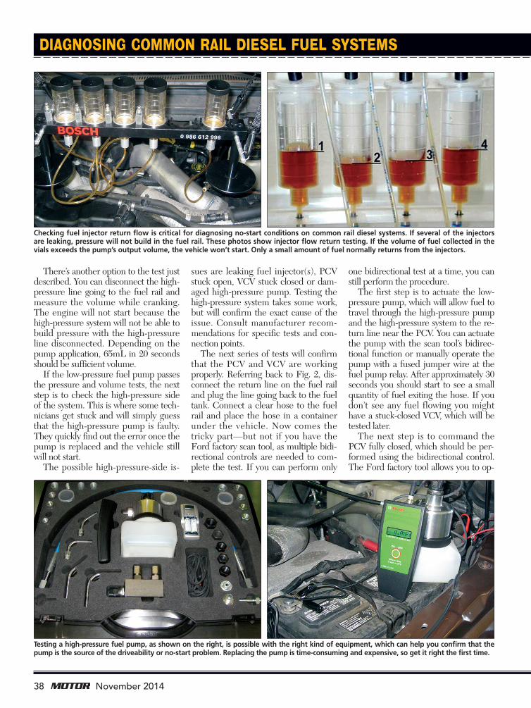
Checking fuel injector return flow is critical for diagnosing no-start conditions on common rail diesel systems. If several of the injectorsare leaking, pressure will not build in the fuel rail. These photos show injector flow return testing. If the volume of fuel collected in thevials exceeds the pump’s output volume, the vehicle won’t start. Only a small amount of fuel normally returns from the injectors.
Testing a high-pressure fuel pump, as shown on the right, is possible with the right kind of equipment, which can help you confirm that thepump is the source of the driveability or no-start problem. Replacing the pump is time-consuming and expensive, so get it right the first time.
38 November 2014
Pg_EDIT_Diesel:Pg_EDIT_ 10/17/14 8:39 AM Page 5

erate both the low-pressure pump and PCV at the same time,which is very handy. Once the PCV is fully closed, the fuel ex-iting the hose should stop. If it does not, there’s an issue withthe PCV. If the PCV cannot fully close the passage, fuel pres-sure will not build. If the fuel stops flowing, it’s a good idea toperform this test several times to make sure the solenoid isn’tsticking.Next, release the PCV solenoid and move to the VCV sole-
noid. Perform the same test with the VCV. Actuate the VCVand the fuel flow should stop when fully engaged and flowwhen fully open. If the fuel flow does not stop, there’s an is-sue with the VCV.
Note: After the VCV and PCV tests, look at the fuel in thecontainer. If you see any contamination or debris, you knowthe failure is severe and the system will require extensive re-pairs.If the PCV and VCV are functioning properly, the leakage
is occurring somewhere else in the system. The next step inthe process is to check the fuel injectors for return leakage.The photo on the left on the bottom of page 38 shows aBosch tester that can be used to check the return from eachinjector. Following manufacturer recommendations, connectthe tester to the injector return and crank the engine over for20 to 30 seconds while monitoring the vials. Leaking injectorswill be obvious since only a very small amount of fuel will nor-mally return from the injectors while cranking. If the totalleakage from all fuel injectors exceeds the volume output ofthe pump, it will create a no-start condition.If no leakage from the injectors is observed and the PCV
and VCV test good, the only thing left at this point is the high-pressure pump. A number of testers are available that allowyou to verify the output of the high-pressure pump. If theoutput pressure is close to what you see on the scan tool orless than 2000 psi, you’ve confirmed the source of the prob-lem. However, if the pressure is greater than 2000 psi, whichis enough to start the vehicle, you need to go back andrecheck your previous test results. If the high-pressure pumpcan build pressure with a tester connected, it should be ableto do it for the vehicle, which means there still is a leak in thesystem.As you can see, diagnosing and servicing common rail
diesel vehicles are not complicated. You just need to under-stand how all the components work together. One nice thingabout CRD systems is that once you understand how one sys-tem works, the others are very similar in design and opera-tion. The primary differences will be names of componentsand specifications for volumes and pressures.If you’re still undecided about whether you want to take on
diesel work, talk to other technicians who have taken somediesel classes and see what they have to say about servicingthese vehicles. It may not be important to you today, but afterthese vehicles come out of warranty, you might be in a goodposition to generate some new opportunities for your shop.
39November 2014
TThhiiss aarrttiiccllee ccaann bbee ffoouunndd oonnlliinnee aatt wwwwww..mmoottoorrmmaaggaazziinnee..ccoomm..
Circle #22
Pg_EDIT_Diesel:Pg_EDIT_ 10/21/14 11:54 AM Page 6