a dedicated catalogue lockout tagout · a dedicated catalogue lockout tagout safety padlocks •...
TRANSCRIPT

A Dedicated Catalogue
Lockout TagoutSafety Padlocks • Hasps • Lockout Devices Lockout Kits • Lockout Tags • Shadow Boards Lockboxes • Lockout Tagout Stations • Lockout Signs
2
Please note...that the operations and procedures outlined in this guide booklet are generalised and therefore strict compliance with other statutory requirements may be necessary under specific circumstances.
In no event shall ARCO be liable for any direct, indirect, punitive, incidental, special consequential damages, to property or life, whatsoever arising out of or connected with the use or misuse of it’s products.
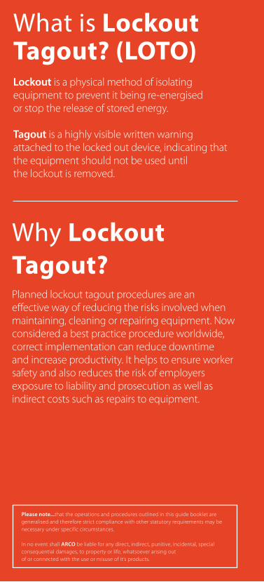
What is Lockout Tagout? (LOTO)Lockout is a physical method of isolating equipment to prevent it being re-energised or stop the release of stored energy.
Tagout is a highly visible written warning attached to the locked out device, indicating that the equipment should not be used until the lockout is removed.
Why Lockout Tagout?Planned lockout tagout procedures are an effective way of reducing the risks involved when maintaining, cleaning or repairing equipment. Now considered a best practice procedure worldwide, correct implementation can reduce downtime and increase productivity. It helps to ensure worker safety and also reduces the risk of employers exposure to liability and prosecution as well as indirect costs such as repairs to equipment.
3
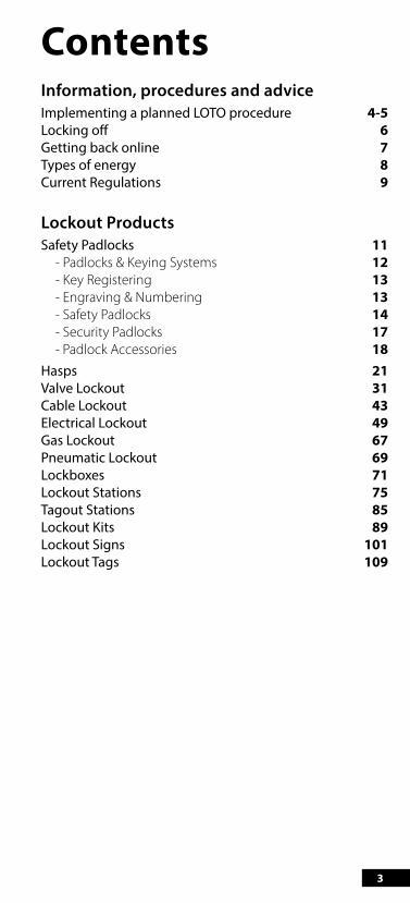
ContentsInformation, procedures and adviceImplementing a planned LOTO procedure 4-5Locking off 6Getting back online 7Types of energy 8Current Regulations 9
Lockout ProductsSafety Padlocks 11 - Padlocks & Keying Systems 12 - Key Registering 13 - Engraving & Numbering 13 - Safety Padlocks 14 - Security Padlocks 17 - Padlock Accessories 18Hasps 21Valve Lockout 31Cable Lockout 43Electrical Lockout 49Gas Lockout 67Pneumatic Lockout 69Lockboxes 71Lockout Stations 75Tagout Stations 85Lockout Kits 89Lockout Signs 101Lockout Tags 109
4
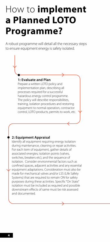
1: Evaluate and Plan Prepare a written LOTO policy and implementation plan, describing all processes required for a successful hazardous energy control programme. The policy will describe responsibilities, training, isolation procedures and restoring equipment to normal operation, contractor control, LOTO products, permits to work, etc.
2: Equipment AppraisalIdentify all equipment requiring energy isolation during maintenance, cleaning or repair activities. For each item of equipment, gather details of associated energies, isolation points (valves, switches, breakers etc), and the sequence of isolation. Consider environmental factors such as con�ned spaces, adjacent activities and any essential equipment adaptations. Consideration must also be made for mechanical valves and/or LSS (Life Safety Systems) that are required to remain ON for safety purposes during these activities. Speci�c “On State” isolation must be included as required and possible downstream e�ects of same must be risk assessed and documented.
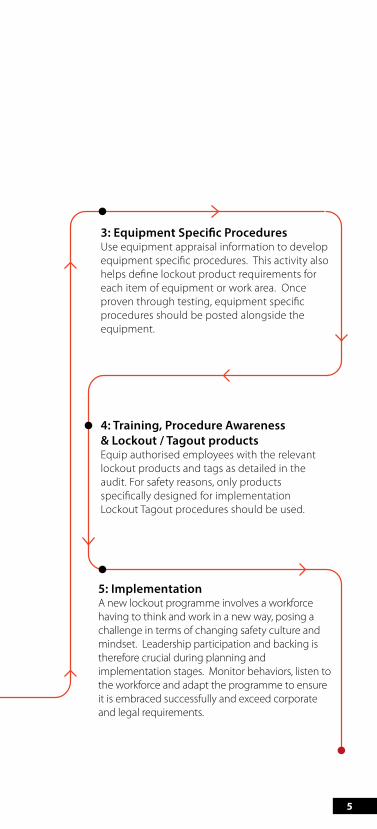
3: Equipment Speci�c ProceduresUse equipment appraisal information to develop equipment speci�c procedures. This activity also helps de�ne lockout product requirements for each item of equipment or work area. Once proven through testing, equipment speci�c procedures should be posted alongside the equipment.
4: Training, Procedure Awareness & Lockout / Tagout productsEquip authorised employees with the relevant lockout products and tags as detailed in the audit. For safety reasons, only products speci�cally designed for implementation Lockout Tagout procedures should be used.
5: ImplementationA new lockout programme involves a workforce having to think and work in a new way, posing a challenge in terms of changing safety culture and mindset. Leadership participation and backing is therefore crucial during planning and implementation stages. Monitor behaviors, listen to the workforce and adapt the programme to ensure it is embraced successfully and exceed corporate and legal requirements.
How to implement a Planned LOTO Programme?A robust programme will detail all the necessary steps to ensure equipment energy is safety isolated.
5
1: Evaluate and Plan Prepare a written LOTO policy and implementation plan, describing all processes required for a successful hazardous energy control programme. The policy will describe responsibilities, training, isolation procedures and restoring equipment to normal operation, contractor control, LOTO products, permits to work, etc.
2: Equipment AppraisalIdentify all equipment requiring energy isolation during maintenance, cleaning or repair activities. For each item of equipment, gather details of associated energies, isolation points (valves, switches, breakers etc), and the sequence of isolation. Consider environmental factors such as con�ned spaces, adjacent activities and any essential equipment adaptations. Consideration must also be made for mechanical valves and/or LSS (Life Safety Systems) that are required to remain ON for safety purposes during these activities. Speci�c “On State” isolation must be included as required and possible downstream e�ects of same must be risk assessed and documented.
3: Equipment Speci�c ProceduresUse equipment appraisal information to develop equipment speci�c procedures. This activity also helps de�ne lockout product requirements for each item of equipment or work area. Once proven through testing, equipment speci�c procedures should be posted alongside the equipment.
4: Training, Procedure Awareness & Lockout / Tagout productsEquip authorised employees with the relevant lockout products and tags as detailed in the audit. For safety reasons, only products speci�cally designed for implementation Lockout Tagout procedures should be used.
5: ImplementationA new lockout programme involves a workforce having to think and work in a new way, posing a challenge in terms of changing safety culture and mindset. Leadership participation and backing is therefore crucial during planning and implementation stages. Monitor behaviors, listen to the workforce and adapt the programme to ensure it is embraced successfully and exceed corporate and legal requirements.
6
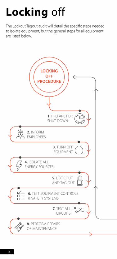
Locking offThe Lockout Tagout audit will detail the specific steps needed to isolate equipment, but the general steps for all equipment are listed below.
1. PREPARE FOR SHUT DOWN
LOCKINGOFF
PROCEDURE
GETTING BACK
ONLINE
2. INFORM EMPLOYEES
3. TURN OFF EQUIPMENT
4. ISOLATE ALLENERGY SOURCES
5. LOCK OUT AND TAG OUT
6. TEST EQUIPMENT CONTROLS & SAFETY SYSTEMS
7. TEST ALL CIRCUITS
8. PERFORM REPAIRSOR MAINTENANCE
1. CHECK THAT ALL WORK HAS BEEN COMPLETED
2. CHECK THAT SYSTEM AND ALL PERSONNEL ARE CLEAR
3. RE-INSTALL GUARDS AND REMOVE BLOCKS
4. REMOVE ALL INDIVIDUAL LOCKS AND DEVICES
5. RE-CONNECT ALL ENERGY SOURCES AND TEST THE SYSTEM
6. REMOVE ALL RELEVANT TAGS & SIGNAGE
7. NOTIFY EMPLOYEES THAT THE EQUIPMENT IS READY TO USE
7
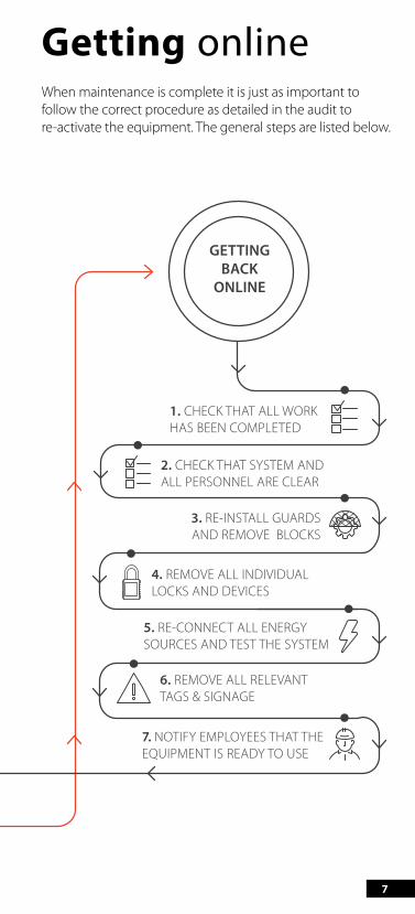
Getting onlineWhen maintenance is complete it is just as important to follow the correct procedure as detailed in the audit to re-activate the equipment. The general steps are listed below.
1. PREPARE FOR SHUT DOWN
LOCKINGOFF
PROCEDURE
GETTING BACK
ONLINE
2. INFORM EMPLOYEES
3. TURN OFF EQUIPMENT
4. ISOLATE ALLENERGY SOURCES
5. LOCK OUT AND TAG OUT
6. TEST EQUIPMENT CONTROLS & SAFETY SYSTEMS
7. TEST ALL CIRCUITS
8. PERFORM REPAIRSOR MAINTENANCE
1. CHECK THAT ALL WORK HAS BEEN COMPLETED
2. CHECK THAT SYSTEM AND ALL PERSONNEL ARE CLEAR
3. RE-INSTALL GUARDS AND REMOVE BLOCKS
4. REMOVE ALL INDIVIDUAL LOCKS AND DEVICES
5. RE-CONNECT ALL ENERGY SOURCES AND TEST THE SYSTEM
6. REMOVE ALL RELEVANT TAGS & SIGNAGE
7. NOTIFY EMPLOYEES THAT THE EQUIPMENT IS READY TO USE

8
Types of energyDangerous energy sources can take many forms, including:
Electrical energyCommonly found powering nearly all workplace equipment
Hydraulic energyCommonly found powering forklifts, cutting equipment and pumps
Mechanical energyCommonly found in all machinery with moving parts
Thermal energyCommonly found in ovens or freezers (hot or cold)
Pneumatic energyCommonly found powering machinery via compressed air or gas
PotentialCommonly found in compressed springs or suspended weights
9
Current Regulations UK and Ireland health & safety legislation is established on a framework that is not wholly prescriptive, being goal setting in nature, emphasising self-regulation, risk assessment and workforce involvement in the control of health and safety. As pioneered by US legislation and subsequent EU legisliation.The Health & Safety at Work etc. Act 1974 places general duties on employers to ensure, so far as reasonably practicable, the health, safety and welfare at work of their employees, including a requirement to provide and maintain safe plant and equipment. The Management of Health & Safety at Work Regulations 1999 require an employer to carry out a risk assessment of activities, introduce safe systems of work, coordinate activities and provide training. Isolation requirements are highlighted under specific UK and Ireland regulations.
In the UK, the following regulations govern the control of hazardous energy (CHE):
BS7671:2008(2011) “Requirements for Electrical Installations. IET Wiring Regulations.” 17th Edition
537.2.2.4: Provision shall be made for securing off-load isolating devices against inadvertent or unauthorised opening.
537.3.1.2: Suitable means shall be provided to prevent electrical powered equipment becoming unintentionally reactivated.
Provision and Use of Work Equipment Regulations 1998
Regulation 19 (1): Every employer shall ensure that where appropriate work equipment is provided with suitable means to isolate it from all its sources of energy.
In Ireland, the legislation in force is:
Safety, Health and Welfare at Work Regulations 2007.All work equipment is fitted with clearly identifiable means to isolate it from all its energy sources, and
The reconnecting of the work equipment to its energy sources poses no risk to the employees concerned.
EUCEE89/655 “Council Directive 89/655/EEC of 30 November 1989 concerning the minimum safety and health requirements for the use of work equipment by workers at work”
Article 19: The employer is committed to guarantee the safety and protection of employees and to take necessary measures to reduce risks to the minimum possible
Article 46: The employer must ensure that all safety procedures are strictly implemented and regularly reviewed by appropriate means Employers must use all necessary tools to carry out maintenance they are responsible for and to aid them in the case of accident or emergency
Article 49: When carrying out isolated maintenance, the equipment must be clearly labelled Isolation of equipment from all possible electrical energy sources; lock-out of devices in the ‘off’ position; verification of isolation of all energy sources close to the maintenance area
USAOSHA 1910.147 “The Control of Hazardous Energy (Lockout/Tagout), Title 29 Code of Federal Regulations”
1910.147 (c)(5)(ii)(B): Standardised. Lockout and tagout devices shall be standardised within the facility in at least one of the following criteria: Colour; shape; or size; and additionally, in the case of tagout devices, print and format shall be standardised
1910.147 (c)(5)(ii)(C): Devices must be capable of withstanding the environment to which they are exposed for the maximum time of exposure expected
1910.147(c)(5)(ii)(C)(1): Lockout devices shall be substantial enough to prevent removal without the use of excessive force or unusual techniques, such as with the use of bolt cutters or other metal cutting tools
1910.147(c)(5)(ii)(C)(2): Tagout devices, including their means of attachment, shall be substantial enough to prevent inadvertent or accidential removal
1910.147(c)(5)(ii)(C)(2): Lockout devices and tagout devices shall indicate the identity of the employee applying the device(s)

The correct use of safety padlocks saves lives.

GATE VALVE COVERSSAFETY LOCKOUT PADLOCKSHIGH SECURITY SAFETY PADLOCKS DESIGNED WITH THE USER IN MIND
12
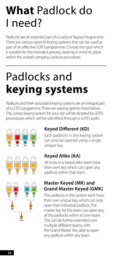
What Padlock do I need?Padlocks are an essential part of a Lockout Tagout Programme. There are various types of keying systems that can be used as part of an effective LOTO programme. Choose the type which is suitable for the intended process, bearing in mind its place within the overall company Lockout procedure.
Padlocks and keying systemsPadlocks and their associated keying systems are an integral part of a LOTO programme. There are varying options listed below. The correct keying system for your site will be dictated by LOTO procedures which will be identified through a LOTO audit.
Keyed Different (KD)Each padlocks in this keying system can only be opened using a single unique key.
Keyed Alike (KA)All locks in a keyed alike team have their own key which can open any padlock within that team.
Master Keyed (MK) and Grand Master Keyed (GMK)The padlocks in this system each have their own unique key, which can only open that individual padlock. The master key for this team can open any of the padlocks within its own team. This can be further extended over multiple different teams, with the Grand Master Key able to open any padlock within any team.

13
Key RegisteringA key registering system is recommended when issuing padlocks as part of a Planned Lockout Tagout Programme and used correctly it can prevent duplicate keys and improve safety. By registering your system you will be issued a unique identification reference, and by using this reference when ordering additional padlocks in the future we can ensure that your keys will not be duplicated.
The additional use of key charting within your organisation will provide you with the means to easily identify who the padlock & key has been issued to and when it was issued. With the option of engraving padlocks & keys with a unique ID number, key charting becomes even more effective.
TIP: Ensure you order your padlocks from the same supplier and state your Unique Identification Reference when ordering!
Engraving & NumberingTo reinforce a key registering programme, safety padlocks can be laser etched with names, registration numbers, company details or other identifying information.
ID NUMBERID
NUMBER

14
Safety Lockout PadlocksCompact high security padlocks designed with the user in mind. The nylon body is ribbed for easy gripping and handling with an individually keyed to differ 6-pin lock which will not release the key until the shackle is closed.
• 6-pin precision-machined cylinder for extra security
• Reinforced nylon body is non-conductive, non-sparkingand resistant to chemicals and corrosion
• Colour coded for easy identification with aphoto-luminescent label
• Key retaining feature• Individually keyed locks for optimum security• Each padlock is supplied boxed with 1 key and keyring
Compact Safety Lockout Padlocks
Colour Code
Red 5578140
Yellow 5578141
Green 5578142
Blue 5578143
Black 5578144
Orange 5578145
SAFETY PADLOCKS
Did you know...that we have keyed alike options available for these compact safety padlocks.
15
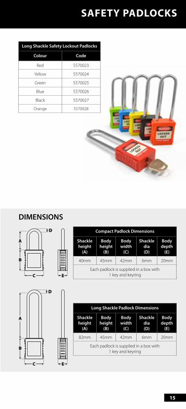
Long Shackle Safety Lockout Padlocks
Colour Code
Red 5570023
Yellow 5570024
Green 5570025
Blue 5570026
Black 5570027
Orange 5570028
SAFETY PADLOCKS
Compact Padlock Dimensions
Shackle height
(A)
Body height
(B)
Body width
(C)
Shackle dia (D)
Body depth
(E)
40mm 45mm 42mm 6mm 20mm
Each padlock is supplied in a box with 1 key and keyring
Long Shackle Padlock Dimensions
Shackle height
(A)
Body height
(B)
Body width
(C)
Shackle dia (D)
Body depth
(E)
82mm 45mm 42mm 6mm 20mm
Each padlock is supplied in a box with 1 key and keyring
A
C E
B
D
A
C E
B
D
DIMENSIONS
16
SAFETY PADLOCKS
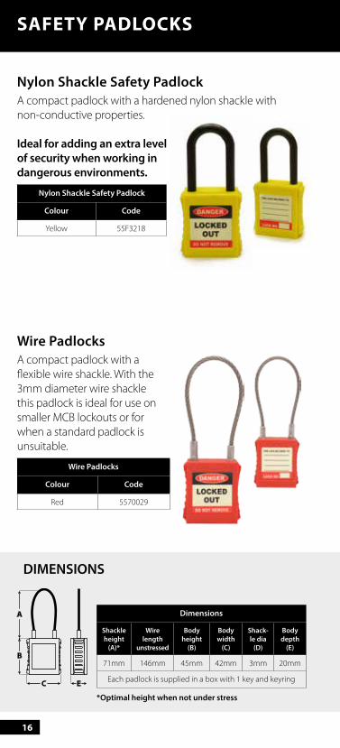
Nylon Shackle Safety PadlockA compact padlock with a hardened nylon shackle with non-conductive properties.
Ideal for adding an extra level of security when working in dangerous environments.
Nylon Shackle Safety Padlock
Colour Code
Yellow 55F3218
Wire PadlocksA compact padlock with a flexible wire shackle. With the 3mm diameter wire shackle this padlock is ideal for use on smaller MCB lockouts or for when a standard padlock is unsuitable.
Wire Padlocks
Colour Code
Red 5570029
Dimensions
Shackle height
(A)*
Wire length
unstressed
Body height
(B)
Body width
(C)
Shack-le dia
(D)
Body depth
(E)
71mm 146mm 45mm 42mm 3mm 20mm
Each padlock is supplied in a box with 1 key and keyring
A
C E
B
DIMENSIONS
*Optimal height when not under stress
17
SECURITY PADLOCKS
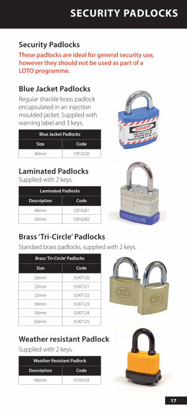
Security PadlocksThese padlocks are ideal for general security use, however they should not be used as part of a LOTO programme.
Blue Jacket PadlocksRegular shackle brass padlock encapsulated in an injection moulded jacket. Supplied with warning label and 3 keys.
Blue Jacket Padlocks
Size Code
40mm 55F3220
Laminated PadlocksSupplied with 2 keys.
Laminated Padlocks
Description Code
40mm 55F4281
50mm 55F4282
Brass ‘Tri-Circle’ PadlocksStandard brass padlocks, supplied with 2 keys.
Brass ‘Tri-Circle’ Padlocks
Size Code
20mm 55AT120
25mm 55AT121
32mm 55AT122
38mm 55AT123
50mm 55AT124
63mm 55AT125
Weather resistant PadlockSupplied with 2 keys.
Weather Resistant Padlock
Description Code
40mm 5570103
18
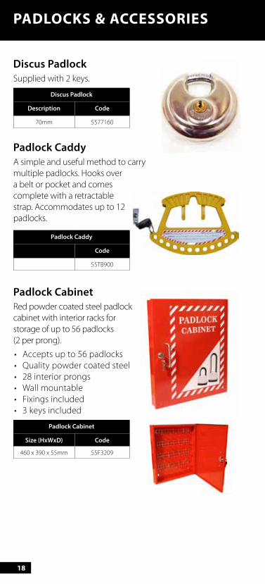
Discus PadlockSupplied with 2 keys.
Discus Padlock
Description Code
70mm 5577160
Padlock CaddyA simple and useful method to carry multiple padlocks. Hooks over a belt or pocket and comes complete with a retractable strap. Accommodates up to 12 padlocks.
Padlock Caddy
Code
55TB900
Padlock CabinetRed powder coated steel padlock cabinet with interior racks for storage of up to 56 padlocks (2 per prong).
• Accepts up to 56 padlocks• Quality powder coated steel• 28 interior prongs• Wall mountable• Fixings included• 3 keys included
Padlock Cabinet
Size (HxWxD) Code
460 x 390 x 55mm 55F3209
PADLOCKS & ACCESSORIES
19
ACCESSORIES
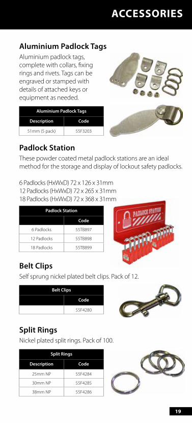
Aluminium Padlock TagsAluminium padlock tags, complete with collars, fixing rings and rivets. Tags can be engraved or stamped with details of attached keys or equipment as needed.
Aluminium Padlock Tags
Description Code
51mm (5 pack) 55F3203
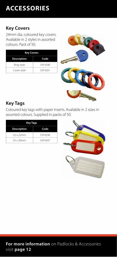
Padlock StationThese powder coated metal padlock stations are an ideal method for the storage and display of lockout safety padlocks.
6 Padlocks (HxWxD) 72 x 126 x 31mm 12 Padlocks (HxWxD) 72 x 265 x 31mm 18 Padlocks (HxWxD) 72 x 368 x 31mm
Padlock Station
Code
6 Padlocks 55TB897
12 Padlocks 55TB898
18 Padlocks 55TB899
Belt ClipsSelf sprung nickel plated belt clips. Pack of 12.
Belt Clips
Code
55F4280
Split RingsNickel plated split rings. Pack of 100.
Split Rings
Description Code
25mm NP 55F4284
30mm NP 55F4285
38mm NP 55F4286
20
Key Covers24mm dia. coloured key covers. Available in 2 styles in assorted colours. Pack of 50.
Key Covers
Description Code
Ring style 55F4290
Cover style 55F4291
Key TagsColoured key tags with paper inserts. Available in 2 sizes in assorted colours. Supplied in packs of 50.
Key Tags
Description Code
52 x 22mm 55F4296
55 x 30mm 55F4297
ACCESSORIES
For more information on Padlocks & Accessories visit page 12
21
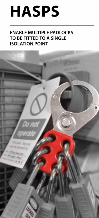
GATE VALVE COVERSHASPSENABLE MULTIPLE PADLOCKS TO BE FITTED TO A SINGLE ISOLATION POINT
22
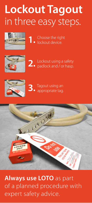
Lockout Tagout in three easy steps.
1. Choose the right lockout device.
2. Lockout using a safety padlock and / or hasp.
3. Tagout using an appropriate tag.
Always use LOTO as part of a planned procedure with expert safety advice.
23
What are Hasps?Often more than one padlock needs to be fitted to an isolation point, and to ensure you can do this a hasp can be fitted to expand the number of lockout points available. The design of a hasp ensures that all the padlocks need to be removed before the hasp can be detached and the equipment re-energised.
Using HaspsA hasp is placed through the primary isolating point on the locking out device, once closed it provides multiple points for authorised persons to place their own individual padlock on the hasp. The system is then locked out, preventing any re-energising until all padlocks are removed.
Removing the padlocks allows removal of the hasp before attempting re-energisation.
Don’t forget Padlocks and Tags should always be used...
Find Padlocks on page 14 and find Tags on page 112.
24
HASPS
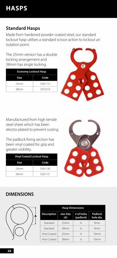
Standard HaspsMade from hardened powder coated steel, our standard lockout hasp utilises a standard scissor action to lockout an isolation point.
The 25mm version has a double locking arrangement and 38mm has single locking.
Economy Lockout Hasp
Size Code
25mm 5581115
38mm 55F3219
Manufactured from high tensile steel sheet which has been electro-plated to prevent rusting.
The padlock fixing section has been vinyl coated for grip and greater visibility.
Vinyl Coated Lockout Hasp
Size Code
25mm 5581130
38mm 5581131
Hasp Dimensions
Description Jaw Size(A)
# of holes(padlock)
Padlockhole dia.
Standard 25mm 6 9mm
Standard 38mm 6 9mm
Vinyl Coated 25mm 6 10mm
Vinyl Coated 38mm 6 10mm
A
DIMENSIONS
25
HASPS
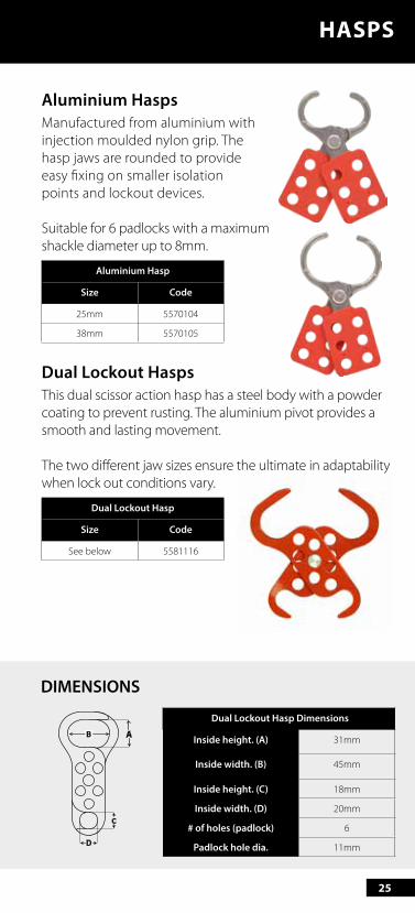
Aluminium HaspsManufactured from aluminium with injection moulded nylon grip. The hasp jaws are rounded to provide easy fixing on smaller isolation points and lockout devices.
Suitable for 6 padlocks with a maximum shackle diameter up to 8mm.
Aluminium Hasp
Size Code
25mm 5570104
38mm 5570105
Dual Lockout HaspsThis dual scissor action hasp has a steel body with a powder coating to prevent rusting. The aluminium pivot provides a smooth and lasting movement.
The two different jaw sizes ensure the ultimate in adaptability when lock out conditions vary.
Dual Lockout Hasp
Size Code
See below 5581116
Dual Lockout Hasp Dimensions
Inside height. (A) 31mm
Inside width. (B) 45mm
Inside height. (C) 18mm
Inside width. (D) 20mm
# of holes (padlock) 6
Padlock hole dia. 11mm
A
DIMENSIONS
26
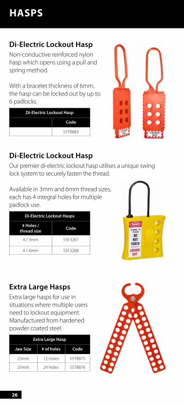
Di-Electric Lockout HaspNon-conductive reinforced nylon hasp which opens using a pull and spring method.
With a bracelet thickness of 6mm, the hasp can be locked out by up to 6 padlocks.
Di-Electric Lockout Hasp
Code
55TB883
Di-Electric Lockout HaspOur premier di-electric lockout hasp utilises a unique swing lock system to securely fasten the thread.
Available in 3mm and 6mm thread sizes, each has 4 integral holes for multiple padlock use.
Di-Electric Lockout Hasps
# Holes / thread size Code
4 / 3mm 55F3267
4 / 6mm 55F3268
Extra Large HaspsExtra large hasps for use in situations where multiple users need to lockout equipment. Manufactured from hardened powder coated steel.
Extra Large Hasp
Jaw Size # of holes Code
25mm 12 Holes 55TB875
25mm 24 Holes 55TB876
HASPS
27
HASPS
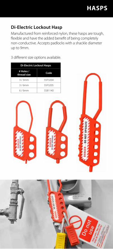
Di-Electric Lockout HaspManufactured from reinforced nylon, these hasps are tough, flexible and have the added benefit of being completely non-conductive. Accepts padlocks with a shackle diameter up to 9mm.
3 different size options available.
Di-Electric Lockout Hasps
# Holes / thread size Code
3 / 3mm 55F3204
3 / 6mm 55F3205
6 / 6mm 5581140
28
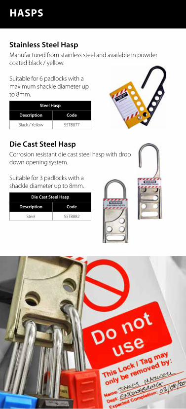
Stainless Steel HaspManufactured from stainless steel and available in powder coated black / yellow.
Suitable for 6 padlocks with a maximum shackle diameter up to 8mm.
Steel Hasp
Description Code
Black / Yellow 55TB877
Die Cast Steel HaspCorrosion resistant die cast steel hasp with drop down opening system.
Suitable for 3 padlocks with a shackle diameter up to 8mm.
Die Cast Steel Hasp
Description Code
Steel 55TB882
HASPS

29
Sign HaspsManufactured from powder coated aluminium, this hasp combines the benefits of a standard hasp and tag simultaneously.
Supplied with spare label for detailing any subsequent lockout uses.
Sign Hasp
Size Code
See dimensions 5581120
Similar to the above hasp, this version has a smaller head making them more suitable to apply in less accessible locations.
Available in three sizes.
Sign Hasp
# of holes Code
6 holes 55TB878
8 holes 55TB879
10 holes 55TB880
A
B
DIMENSIONS
Sign Hasp Dimensions
Insideheight. (A)
Insidewidth. (B)
# of holes(padlock)
Padlockhole dia.
43mm 81mm 10 8mm
Sign Hasp Dimensions
Inside height. (A)
25mm
A
HASPS

A life is on the line. Always Lockout Tagout.
31
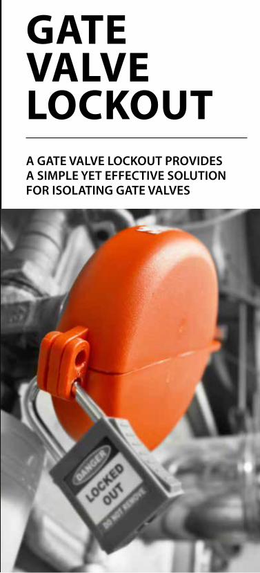
GATE VALVE COVERSGATE VALVE LOCKOUTA GATE VALVE LOCKOUT PROVIDES A SIMPLE YET EFFECTIVE SOLUTION FOR ISOLATING GATE VALVES
32 33
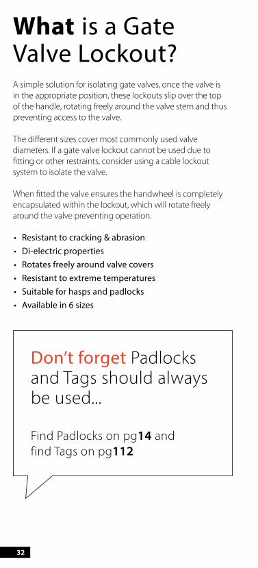
What is a Gate Valve Lockout?A simple solution for isolating gate valves, once the valve is in the appropriate position, these lockouts slip over the top of the handle, rotating freely around the valve stem and thus preventing access to the valve.
The different sizes cover most commonly used valve diameters. If a gate valve lockout cannot be used due to fitting or other restraints, consider using a cable lockout system to isolate the valve.
When fitted the valve ensures the handwheel is completely encapsulated within the lockout, which will rotate freely around the valve preventing operation.
• Resistant to cracking & abrasion• Di-electric properties• Rotates freely around valve covers• Resistant to extreme temperatures• Suitable for hasps and padlocks• Available in 6 sizes
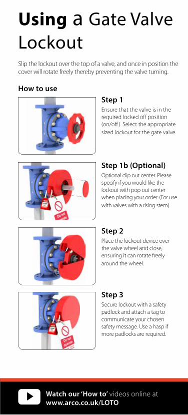
Using a Gate Valve LockoutSlip the lockout over the top of a valve, and once in position thecover will rotate freely thereby preventing the valve turning.
How to useStep 1Ensure that the valve is in the required locked off position (on/off ). Select the appropriate sized lockout for the gate valve.
Step 1b (Optional)Optional clip out center. Pleasespecify if you would like the lockout with pop out centerwhen placing your order. (For use with valves with a rising stem).
Step 2Place the lockout device over the valve wheel and close, ensuring it can rotate freelyaround the wheel.
Step 3Secure lockout with a safety padlock and attach a tag tocommunicate your chosen safety message. Use a hasp ifmore padlocks are required.
Don’t forget Padlocks and Tags should always be used...
Find Padlocks on pg14 and find Tags on pg112
Watch our ‘How to’ videos online at www.arco.co.uk/LOTO
32 33
What is a Gate Valve Lockout?A simple solution for isolating gate valves, once the valve is in the appropriate position, these lockouts slip over the top of the handle, rotating freely around the valve stem and thus preventing access to the valve.
The different sizes cover most commonly used valve diameters. If a gate valve lockout cannot be used due to fitting or other restraints, consider using a cable lockout system to isolate the valve.
When fitted the valve ensures the handwheel is completely encapsulated within the lockout, which will rotate freely around the valve preventing operation.
• Resistant to cracking & abrasion• Di-electric properties• Rotates freely around valve covers• Resistant to extreme temperatures• Suitable for hasps and padlocks• Available in 6 sizes
Using a Gate Valve Lockout Slip the lockout over the top of a valve, and once in position the cover will rotate freely thereby preventing the valve turning.
How to useStep 1Ensure that the valve is in the required locked off position (on/off ). Select the appropriate sized lockout for the gate valve.
Step 1b (Optional)Optional clip out center. Please specify if you would like the lockout with pop out center when placing your order. (For use with valves with a rising stem).
Step 2Place the lockout device over the valve wheel and close, ensuring it can rotate freely around the wheel.
Step 3Secure lockout with a safety padlock and attach a tag to communicate your chosen safety message. Use a hasp if more padlocks are required.
Don’t forget Padlocks and Tags should always be used...
Find Padlocks on pg14 and find Tags on pg112
Watch our ‘How to’ videos online at www.arco.co.uk/LOTO
34
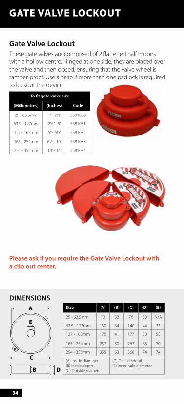
Size (A) (B) (C) (D) (E)
25 - 63.5mm 70 32 76 38 N/A
63.5 - 127mm 130 34 140 44 33
127 - 165mm 170 41 177 50 53
165 - 254mm 257 50 267 63 70
254 - 355mm 355 63 368 74 74
(A) Inside diameter(B) Inside depth(C) Outside diameter
(D) Outside depth(E) Inner hole diameter
A
E
C
B D
Gate Valve LockoutThese gate valves are comprised of 2 flattened half moons with a hollow centre. Hinged at one side, they are placed over the valve and then closed, ensuring that the valve wheel is tamper-proof. Use a hasp if more than one padlock is required to lockout the device.
To fit gate valve size
(Millimetres) (Inches) Code
25 - 63.5mm 1” - 21/2” 5581080
63.5 - 127mm 21/2” - 5” 5581081
127 - 165mm 5” - 61/2” 5581082
165 - 254mm 61/2 - 10” 5581083
254 - 355mm 10” - 14” 5581084
DIMENSIONS
GATE VALVE LOCKOUT
Please ask if you require the Gate Valve Lockout with a clip out center.

35
GATE VALVE COVERS
Extra Large Gate Valve LockoutOur largest sized gate valve lockout is suitable for valve handles of a diameter from 330mm up to 450mm. It also has an integral clip out centre and a built in facility to use 4 padlocks on the unit without the use of a hasp.
When not in use one side of the lockout can fit within the other to allow for ease of transportation and storage.
To fit gate valve size
(Millimetres) (Inches) Code
330 - 450mm 13” - 18” 5570011
Adjustable Gate Valve LockoutThese have 2 separate pieces which whilst in place over the valve are slid into each other to enclose the handle.
This design allows it to fit valve handwheels from 25.5mm through to 165mm diameter.
To fit gate valve size
(Millimetres) (Inches) Code
25 - 165mm 1” - 61/2” 5581090

36
GATE VALVE COVERS
Protect lives. Use Safety Padlocks.
37
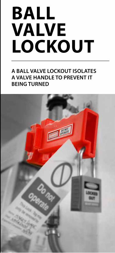
GATE VALVE COVERSBALL VALVE LOCKOUTA BALL VALVE LOCKOUT ISOLATES A VALVE HANDLE TO PREVENT IT BEING TURNED
38 39
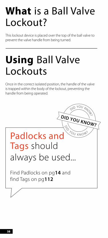
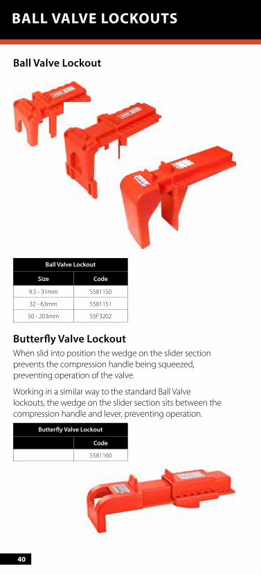
What is a Ball Valve Lockout?This lockout device is placed over the top of the ball valve to prevent the valve handle from being turned.
Using Ball Valve LockoutsOnce in the correct isolated position, the handle of the valve is trapped within the body of the lockout, preventing the handle from being operated.
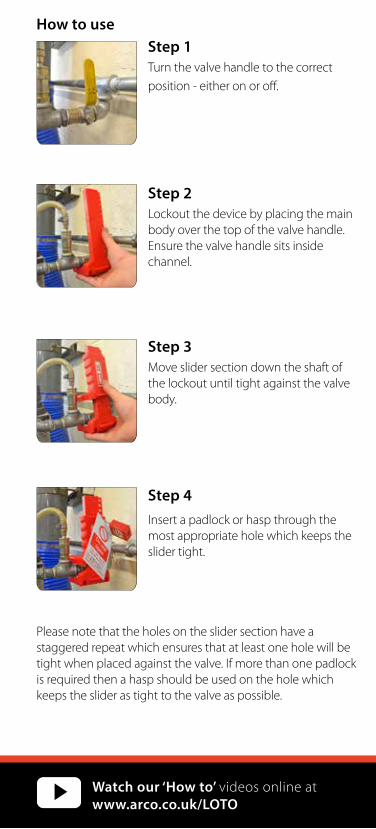
How to useStep 1Turn the valve handle to the correct position - either on or off.
Step 2Lockout the device by placing the main body over the top of the valve handle.Ensure the valve handle sits inside channel.
Step 3Move slider section down the shaft of the lockout until tight against the valve body.
Step 4Insert a padlock or hasp through the most appropriate hole which keeps the slider tight.
Please note that the holes on the slider section have a staggered repeat which ensures that at least one hole will be tight when placed against the valve. If more than one padlock is required then a hasp should be used on the hole which keeps the slider as tight to the valve as possible.
Padlocks and Tags should always be used...Find Padlocks on pg14 and find Tags on pg112
Watch our ‘How to’ videos online at www.arco.co.uk/LOTO
38 39
What is a Ball Valve Lockout?This lockout device is placed over the top of the ball valve to prevent the valve handle from being turned.
Using Ball Valve LockoutsOnce in the correct isolated position, the handle of the valve is trapped within the body of the lockout, preventing the handle from being operated.
How to useStep 1Turn the valve handle to the correct position - either on or off.
Step 2Lockout the device by placing the main body over the top of the valve handle.Ensure the valve handle sits inside channel.
Step 3Move slider section down the shaft of the lockout until tight against the valve body.
Step 4Insert a padlock or hasp through the most appropriate hole which keeps the slider tight.
Please note that the holes on the slider section have a staggered repeat which ensures that at least one hole will be tight when placed against the valve. If more than one padlock is required then a hasp should be used on the hole which keeps the slider as tight to the valve as possible.
Padlocks and Tags should always be used...Find Padlocks on pg14 and find Tags on pg112
Watch our ‘How to’ videos online at www.arco.co.uk/LOTO
40
Ball Valve Lockout
Ball Valve Lockout
Size Code
9.5 - 31mm 5581150
32 - 63mm 5581151
50 - 203mm 55F3202
Butterfly Valve LockoutWhen slid into position the wedge on the slider section prevents the compression handle being squeezed, preventing operation of the valve.
Working in a similar way to the standard Ball Valve lockouts, the wedge on the slider section sits between the compression handle and lever, preventing operation.
Butterfly Valve Lockout
Code
5581160
BALL VALVE LOCKOUTS
41
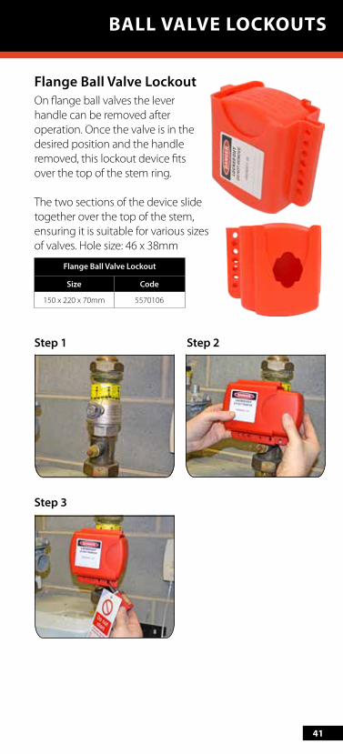
Flange Ball Valve LockoutOn flange ball valves the lever handle can be removed after operation. Once the valve is in the desired position and the handle removed, this lockout device fits over the top of the stem ring.
The two sections of the device slide together over the top of the stem, ensuring it is suitable for various sizes of valves. Hole size: 46 x 38mm
Flange Ball Valve Lockout
Size Code
150 x 220 x 70mm 5570106
Step 1 Step 2
Step 3
BALL VALVE LOCKOUTS

42
BALL VALVE LOCKOUTS
BALL VALVE LOCKOUTS
Responsibility starts with the individual, but the right procedure starts with the employer.

43
CABLE LOCKOUTLOCK OUT MULTIPLE MACHINES IN CLOSE PROXIMITY USING ONE DEVICE
44
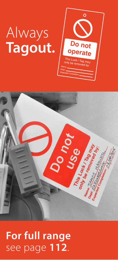
Always Tagout.
For full range see page 112.
This Lock / Tag mayonly be removed by:Name:Dept :Expected Completion:
45
What is a Cable Lockout?Cable lockouts are ideal when there is a need to lockout multiple energy sources with one device or when the design or placement of the energy source prevents other types of lockout being used.
Using Cable Lockouts Use the flexible cable to tie off the energy source and then secure using the grip handle. The handle traps the cable and prevents it from becoming loose. Multiple padlocks can be used on the handle to ensure the safety of multiple workers.
46
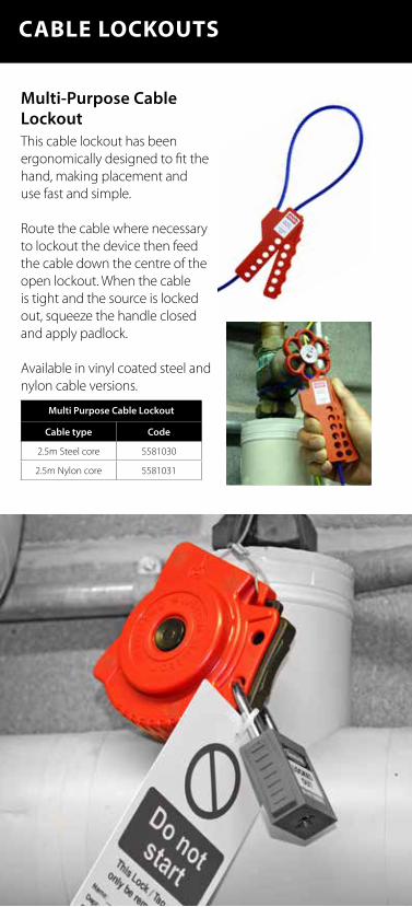
Multi-Purpose Cable LockoutThis cable lockout has been ergonomically designed to fit the hand, making placement and use fast and simple.
Route the cable where necessary to lockout the device then feed the cable down the centre of the open lockout. When the cable is tight and the source is locked out, squeeze the handle closed and apply padlock.
Available in vinyl coated steel and nylon cable versions.
Multi Purpose Cable Lockout
Cable type Code
2.5m Steel core 5581030
2.5m Nylon core 5581031
CABLE LOCKOUTS

47
GATE VALVE COVERS
Step 1:Pull out the cable and route it through the equipment to lockout the device. Feed the cable back to the cable lockout and place the loop around the hook.
Step 2:Push the winding button and the cable will automatically retract, pulling it tight.
Step 3:Push in the black grip handle to lock the cable in place. Affix up to 2 padlocks on the unit (more can be fitted using a hasp) and tagout as appropriate.
Note: To remove, push in the black grip handle to release the cable.
Retractable Cable LockoutThis unique cable lockout has an integral rewinding mechanism, pulling the cable taut once it has been routed to lockout the equipment. It can house up to 2 padlocks of a maximum diameter of 7mm.
Dimensions: 110 x 110 x 40mmCable diameter: 2mm
Retractable Cable Lockout
Cable Length Code
1.8m 5570012
CABLE LOCKOUTS

48
CABLE LOCKOUT
Heavy Duty Cable LockoutA heavy duty cable lockout that can be applied to large valves. Suitable for the most extreme weather conditions including offshore installations.
Thanks to its all metal construction and stainless steel nut this lockout provides reliable and corrosion resistant use. Please note that the stainless steel cable is supplied separately.
Heavy Duty Cable Lockout
Description Code
Lockout only 55TB872
2m stainless steel cable
55TB873
5m stainless steel cable
55TB874
Did you know...we also stock Safety Padlocks and Tagging systems?
Find Padlocks on page 14 and find Tags on page 112
49
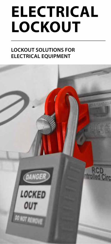
GATE VALVE COVERSELECTRICAL LOCKOUTLOCKOUT SOLUTIONS FOR ELECTRICAL EQUIPMENT
50
What is Electrical Lockout?Isolation of electrical energy is often a cornerstone of a correct lockout tagout programme. Electrical isolation points vary in design and size, and a comprehensive range of electrical lockout equipment is essential to ensure the LOTO procedure is performed safely.
Using Electrical LockoutsMost equipment will require an electric energy source to be locked out as part of the isolation programme. Within the isolation procedure there will be specialised electrical lockouts to be used as detailed within your LOTO audit.
Don’t forget...when using electrical lockouts you also need Safety Padlocks and Tags.
Find Padlocks on page 14 and find Tags on page 112

50 51
Examples of useMini MCB
Universal Circuit Breaker
Tie Bar Lockout
Breaker Lockout
What is Electrical Lockout?Isolation of electrical energy is often a cornerstone of a correct lockout tagout programme. Electrical isolation points vary in design and size, and a comprehensive range of electrical lockout equipment is essential to ensure the LOTO procedure is performed safely.
Using Electrical LockoutsMost equipment will require an electric energy source to be locked out as part of the isolation programme. Within the isolation procedure there will be specialised electrical lockouts to be used as detailed within your LOTO audit.
Don’t forget...when using electrical lockouts you also need Safety Padlocks and Tags.
Find Padlocks on pg14 and find Tags on pg112
52
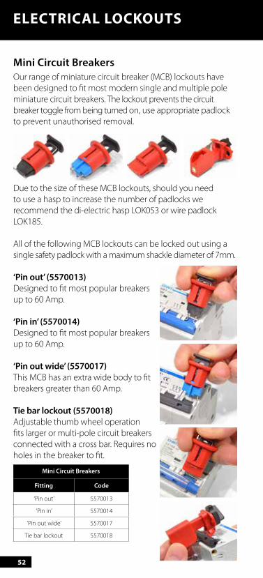
Mini Circuit BreakersOur range of miniature circuit breaker (MCB) lockouts have been designed to fit most modern single and multiple pole miniature circuit breakers. The lockout prevents the circuit breaker toggle from being turned on, use appropriate padlock to prevent unauthorised removal.
Due to the size of these MCB lockouts, should you need to use a hasp to increase the number of padlocks we recommend the di-electric hasp LOK053 or wire padlock LOK185.
All of the following MCB lockouts can be locked out using a single safety padlock with a maximum shackle diameter of 7mm.
‘Pin out’ (5570013)Designed to fit most popular breakers up to 60 Amp.
‘Pin in’ (5570014)Designed to fit most popular breakers up to 60 Amp.
‘Pin out wide’ (5570017)This MCB has an extra wide body to fit breakers greater than 60 Amp.
Tie bar lockout (5570018)Adjustable thumb wheel operation fits larger or multi-pole circuit breakers connected with a cross bar. Requires no holes in the breaker to fit.
Mini Circuit Breakers
Fitting Code
‘Pin out’ 5570013
‘Pin in’ 5570014
‘Pin out wide’ 5570017
Tie bar lockout 5570018
ELECTRICAL LOCKOUTS
53
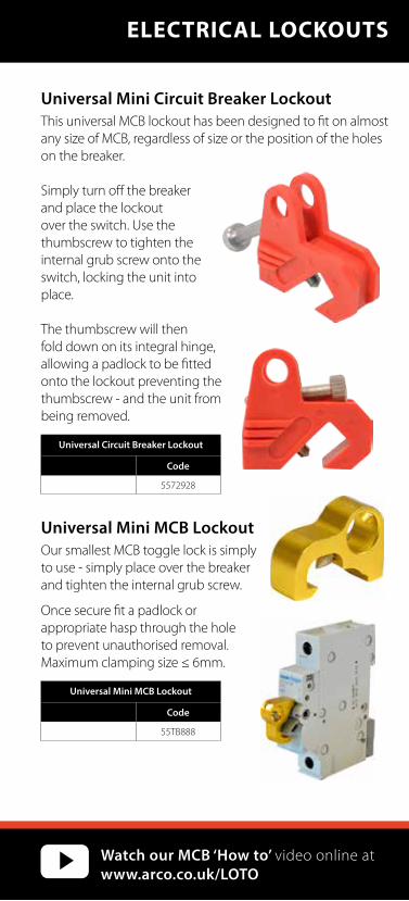
Universal Mini Circuit Breaker LockoutThis universal MCB lockout has been designed to fit on almost any size of MCB, regardless of size or the position of the holes on the breaker.
Simply turn off the breaker and place the lockout over the switch. Use the thumbscrew to tighten the internal grub screw onto the switch, locking the unit into place.
The thumbscrew will then fold down on its integral hinge, allowing a padlock to be fitted onto the lockout preventing the thumbscrew - and the unit from being removed.
Universal Circuit Breaker Lockout
Code
5572928
Universal Mini MCB LockoutOur smallest MCB toggle lock is simply to use - simply place over the breaker and tighten the internal grub screw.
Once secure fit a padlock or appropriate hasp through the hole to prevent unauthorised removal. Maximum clamping size ≤ 6mm.
Universal Mini MCB Lockout
Code
55TB888
ELECTRICAL LOCKOUTS
Watch our MCB ‘How to’ video online at www.arco.co.uk/LOTO
54
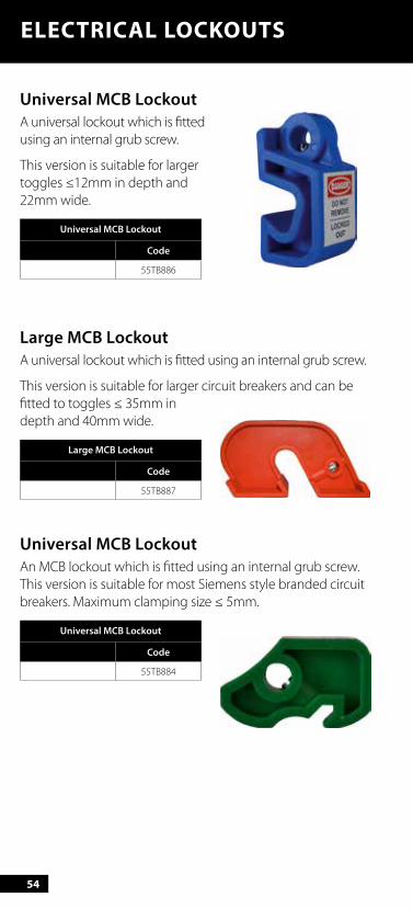
Universal MCB LockoutA universal lockout which is fitted using an internal grub screw.
This version is suitable for larger toggles ≤12mm in depth and 22mm wide.
Universal MCB Lockout
Code
55TB886
Large MCB LockoutA universal lockout which is fitted using an internal grub screw.
This version is suitable for larger circuit breakers and can be fitted to toggles ≤ 35mm in depth and 40mm wide.
Large MCB Lockout
Code
55TB887
Universal MCB LockoutAn MCB lockout which is fitted using an internal grub screw. This version is suitable for most Siemens style branded circuit breakers. Maximum clamping size ≤ 5mm.
Universal MCB Lockout
Code
55TB884
ELECTRICAL LOCKOUTS
55
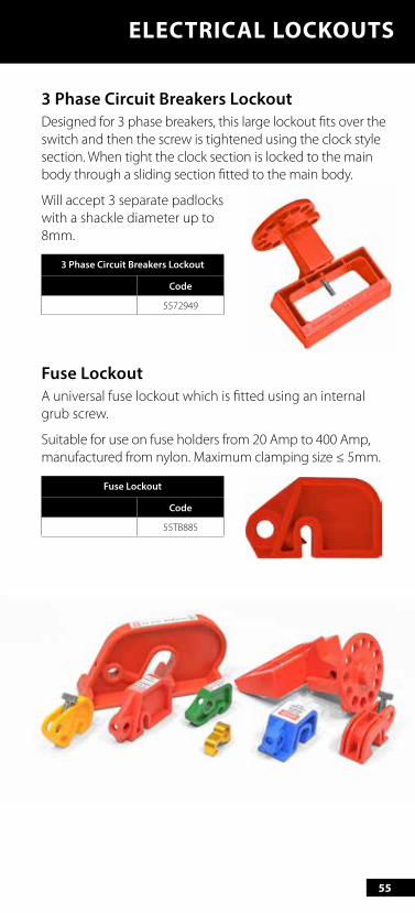
3 Phase Circuit Breakers LockoutDesigned for 3 phase breakers, this large lockout fits over the switch and then the screw is tightened using the clock style section. When tight the clock section is locked to the main body through a sliding section fitted to the main body.
Will accept 3 separate padlocks with a shackle diameter up to 8mm.
3 Phase Circuit Breakers Lockout
Code
5572949
Fuse LockoutA universal fuse lockout which is fitted using an internal grub screw.
Suitable for use on fuse holders from 20 Amp to 400 Amp, manufactured from nylon. Maximum clamping size ≤ 5mm.
Fuse Lockout
Code
55TB885
ELECTRICAL LOCKOUTS
56
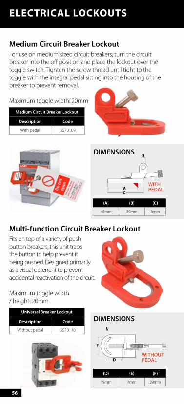
Multi-function Circuit Breaker LockoutFits on top of a variety of push button breakers, this unit traps the button to help prevent it being pushed. Designed primarily as a visual deterrent to prevent accidental reactivation of the circuit.
Maximum toggle width / height: 20mm
Universal Breaker Lockout
Description Code
Without pedal 5570110
DIMENSIONS
(D) (E) (F)
19mm 7mm 29mm
Medium Circuit Breaker LockoutFor use on medium sized circuit breakers, turn the circuit breaker into the off position and place the lockout over the toggle switch. Tighten the screw thread until tight to the toggle with the integral pedal sitting into the housing of the breaker to prevent removal.
Maximum toggle width: 20mm
Medium Circuit Breaker Lockout
Description Code
With pedal 5570109
ELECTRICAL LOCKOUTS
DIMENSIONS
(A) (B) (C)
45mm 39mm 8mm
WITH PEDAL
WITHOUTPEDAL

57
Large Circuit Breaker LockoutDesigned to fit on the largest circuit breakers, turn the circuit breaker into the off position and place the lockout over the toggle switch. Tighten the screw thread until tight to the toggle with the integral pedal sitting into the housing of the breaker to prevent removal.
This unit is available in 2 sizes to allow for fitting to various sizes of breaker.
Maximum toggle height: 20mm - 30mm
30mm20mm
30mm20mm
ELECTRICAL LOCKOUTS
Large Circuit Breaker Lockout
Description Code
Small 20mm) 5570111
Large (30mm) 5570112
DIMENSIONS
BA
C
D
FE G
(A) 70mm
(B) 42mm
(C) 5mm
(D) 24mm
(E) 30mm
(F) 8mm
(G) 25mm
Top
Bottom
58
ELECTRICAL LOCKOUTS
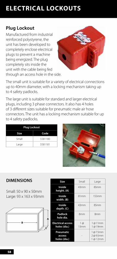
Plug LockoutManufactured from industrial reinforced polystyrene, the unit has been developed to completely enclose electrical plugs to prevent a machine being energized. The plug completely sits inside the unit with the cable being fed through an access hole in the side.
The small unit is suitable for a variety of electrical connections up to 40mm diameter, with a locking mechanism taking up to 4 safety padlocks.
The large unit is suitable for standard and larger electrical plugs, including 3 phase connectors. It also has 4 holes of 3 different sizes suitable for pneumatic male air hose connectors. The unit has a locking mechanism suitable for up to 4 safety padlocks.
Plug Lockout
Size Code
Small 5581180
Large 5581181
Size Small Large
Insideheight. (A)
43mm 85mm
Insidewidth. (B)
81mm 155mm
Insidedepth. (C)
43mm 85mm
Padlockhole dia.
8mm 8mm
Electrical accessholes (dia.)
1 @ 13mm
1 @ 11mm1 @ 19mm
Pneumatic access
holes (dia.)-
1 @ 7.5mm2 @ 9.5mm1 @ 12mm
DIMENSIONS
Small: 50 x 90 x 50mmLarge: 93 x 163 x 93mm
59
ELECTRICAL LOCKOUTS
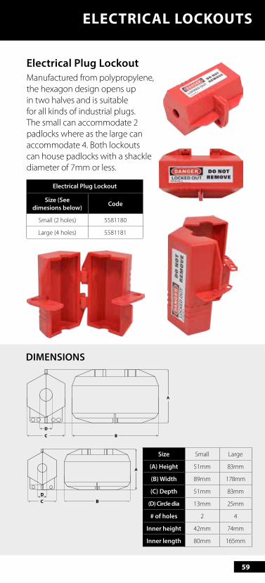
Electrical Plug LockoutManufactured from polypropylene, the hexagon design opens up in two halves and is suitable for all kinds of industrial plugs. The small can accommodate 2 padlocks where as the large can accommodate 4. Both lockouts can house padlocks with a shackle diameter of 7mm or less.
Electrical Plug Lockout
Size (See dimesions below) Code
Small (2 holes) 5581180
Large (4 holes) 5581181
Size Small Large
(A) Height 51mm 83mm
(B) Width 89mm 178mm
(C) Depth 51mm 83mm
(D) Circle dia 13mm 25mm
# of holes 2 4
Inner height 42mm 74mm
Inner length 80mm 165mm
BC
D
BCD
DIMENSIONS
60
ELECTRICAL LOCKOUTS
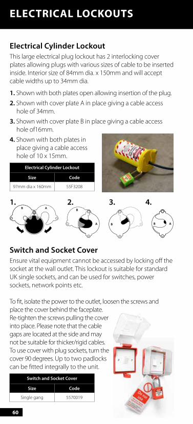
Electrical Cylinder LockoutThis large electrical plug lockout has 2 interlocking cover plates allowing plugs with various sizes of cable to be inserted inside. Interior size of 84mm dia. x 150mm and will accept cable widths up to 34mm dia.
1. Shown with both plates open allowing insertion of the plug.
2. Shown with cover plate A in place giving a cable access hole of 34mm.
3. Shown with cover plate B in place giving a cable access hole of16mm.
4. Shown with both plates in place giving a cable access hole of 10 x 15mm.
Electrical Cylinder Lockout
Size Code
97mm dia x 160mm 55F3208
1. 2. 3. 4.
Switch and Socket CoverEnsure vital equipment cannot be accessed by locking off the socket at the wall outlet. This lockout is suitable for standard UK single sockets, and can be used for switches, power sockets, network points etc.
To fit, isolate the power to the outlet, loosen the screws and place the cover behind the faceplate. Re-tighten the screws pulling the cover into place. Please note that the cable gaps are located at the side and may not be suitable for thicker/rigid cables. To use cover with plug sockets, turn the cover 90 degrees. Up to two padlocks can be fitted integrally to the unit.
Switch and Socket Cover
Size Code
Single gang 5570019
61
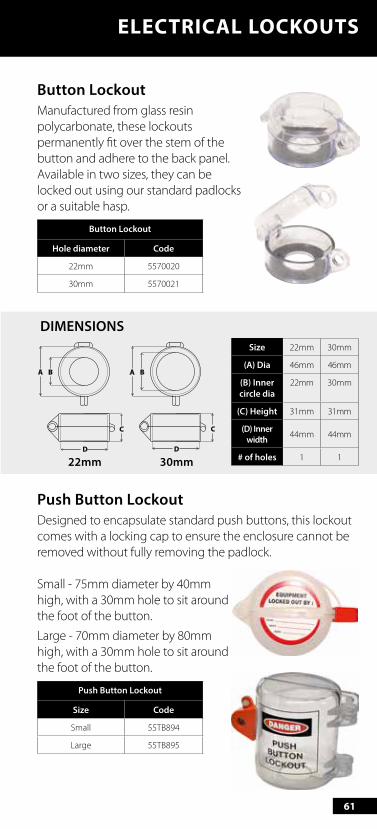
Button Lockout Manufactured from glass resin polycarbonate, these lockouts permanently fit over the stem of the button and adhere to the back panel. Available in two sizes, they can be locked out using our standard padlocks or a suitable hasp.
Button Lockout
Hole diameter Code
22mm 5570020
30mm 5570021
Push Button LockoutDesigned to encapsulate standard push buttons, this lockout comes with a locking cap to ensure the enclosure cannot be removed without fully removing the padlock.
Small - 75mm diameter by 40mm high, with a 30mm hole to sit around the foot of the button.
Large - 70mm diameter by 80mm high, with a 30mm hole to sit around the foot of the button.
Push Button Lockout
Size Code
Small 55TB894
Large 55TB895
ELECTRICAL LOCKOUTS
Size 22mm 30mm
(A) Dia 46mm 46mm
(B) Inner circle dia
22mm 30mm
(C) Height 31mm 31mm
(D) Inner width 44mm 44mm
# of holes 1 1
DIMENSIONS
22mm 30mm
62
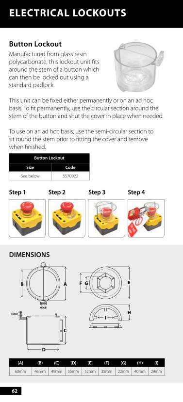
Button LockoutManufactured from glass resin polycarbonate, this lockout unit fits around the stem of a button which can then be locked out using a standard padlock.
This unit can be fixed either permanently or on an ad hoc basis. To fit permanently, use the circular section around the stem of the button and shut the cover in place when needed.
To use on an ad hoc basis, use the semi-circular section to sit round the stem prior to fitting the cover and remove when finished.
Button Lockout
Size Code
See below 5570022
Step 1 Step 2 Step 3 Step 4
ELECTRICAL LOCKOUTS
DIMENSIONS
(A) (B) (C) (D) (E) (F) (G) (H) (I)
60mm 46mm 49mm 55mm 52mm 35mm 22mm 40mm 29mm
63
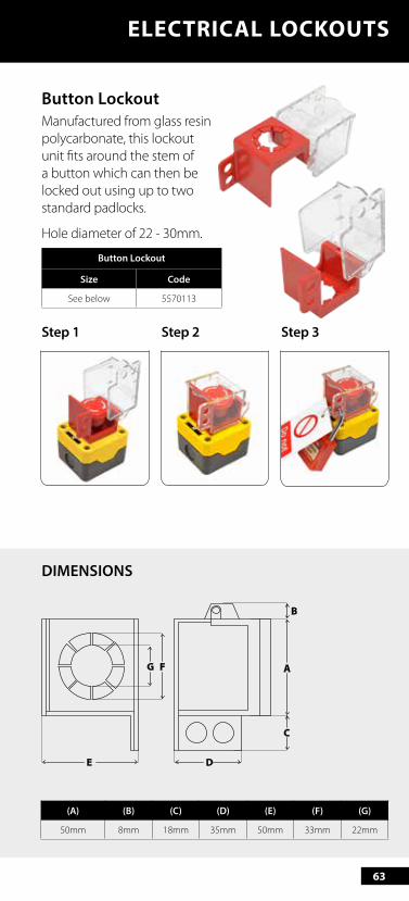
Button LockoutManufactured from glass resin polycarbonate, this lockout unit fits around the stem of a button which can then be locked out using up to two standard padlocks.
Hole diameter of 22 - 30mm.
Button Lockout
Size Code
See below 5570113
Step 1 Step 2 Step 3
ELECTRICAL LOCKOUTS
A
C
B
FG
DE
DIMENSIONS
(A) (B) (C) (D) (E) (F) (G)
50mm 8mm 18mm 35mm 50mm 33mm 22mm
64
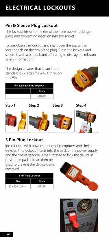
Pin & Sleeve Plug Lockout This lockout fits onto the rim of the male socket, locking in place and preventing insertion into the socket.
To use: Open the lockout and slip it over the top of the locating tab on the rim of the plug. Close the lockout and secure it with a padlock and affix a tag to display the relevant safety information.
The design ensures that it can fit on standard plug sizes from 16A through to 125A.
Pin & Sleeve Plug Lockout
Code
55TB893
Step 1 Step 2 Step 3 Step 4
3 Pin Plug LockoutIdeal for use with power supplies of computers and similar devices. This lockout inserts into the back of the power supply and the circular paddle is then rotated to lock the device in position. A padlock can then be used to prevent the device being removed.
3 Pin Plug Lockout
Size Code
33 x 130 x 29mm 55F3271
ELECTRICAL LOCKOUTS
65
GATE VALVE COVERS
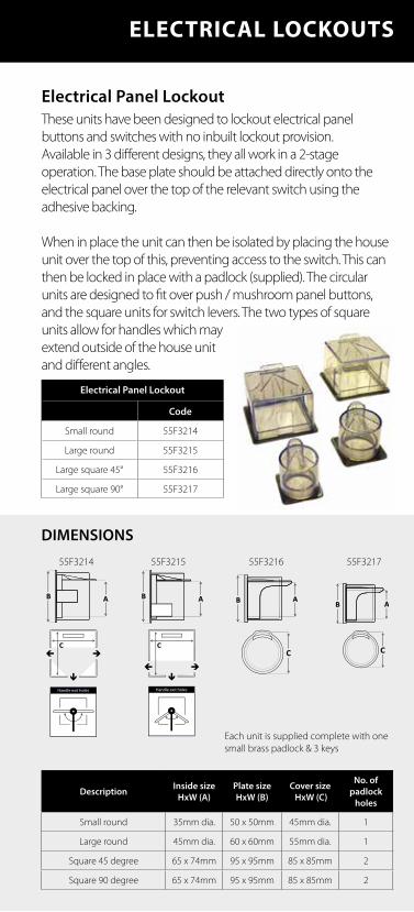
Electrical Panel LockoutThese units have been designed to lockout electrical panel buttons and switches with no inbuilt lockout provision.Available in 3 different designs, they all work in a 2-stage operation. The base plate should be attached directly onto the electrical panel over the top of the relevant switch using the adhesive backing.
When in place the unit can then be isolated by placing the house unit over the top of this, preventing access to the switch. This can then be locked in place with a padlock (supplied). The circular units are designed to fit over push / mushroom panel buttons, and the square units for switch levers. The two types of square units allow for handles which may extend outside of the house unit and different angles.
Electrical Panel Lockout
Code
Small round 55F3214
Large round 55F3215
Large square 45° 55F3216
Large square 90° 55F3217
ELECTRICAL LOCKOUTS
DIMENSIONS
55F3214 55F3215 55F3216 55F3217
Description Inside sizeHxW (A)
Plate sizeHxW (B)
Cover size HxW (C)
No. ofpadlock
holes
Small round 35mm dia. 50 x 50mm 45mm dia. 1
Large round 45mm dia. 60 x 60mm 55mm dia. 1
Square 45 degree 65 x 74mm 95 x 95mm 85 x 85mm 2
Square 90 degree 65 x 74mm 95 x 95mm 85 x 85mm 2
Each unit is supplied complete with one small brass padlock & 3 keys
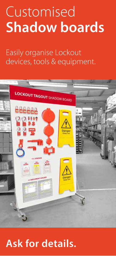
Customised Shadow boards
Easily organise Lockout devices, tools & equipment.
Ask for details.
67
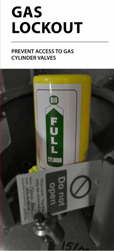
GAS LOCKOUTPREVENT ACCESS TO GAS CYLINDER VALVES
68
GAS LOCKOUT
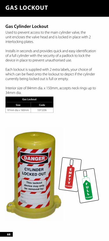
Gas Cylinder Lockout Used to prevent access to the main cylinder valve, the unit encloses the valve head and is locked in place with 2 interlocking plates.
Installs in seconds and provides quick and easy identification of a full cylinder with the security of a padlock to lock the device in place to prevent unauthorised use.
Each lockout is supplied with 2 extra labels, your choice of which can be fixed onto the lockout to depict if the cylinder currently being locked out is full or empty.
Interior size of 84mm dia. x 150mm, accepts neck rings up to 34mm dia.
Gas Lockout
Size Code
97mm dia x 160mm 55F3206
69
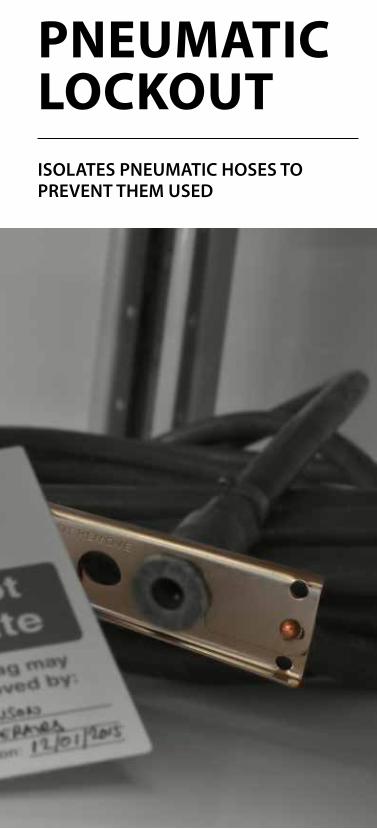
GATE VALVE COVERSPNEUMATIC LOCKOUTISOLATES PNEUMATIC HOSES TO PREVENT THEM USED
70
PNEUMATIC LOCKOUT
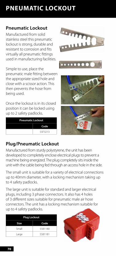
Pneumatic Lockout Manufactured from solid stainless steel this pneumatic lockout is strong, durable and resistant to corrosion and fits virtually all pneumatic fittings used in manufacturing facilities.
Simple to use, place the pneumatic male fitting between the appropriate sized hole and close with a scissor action. This then prevents the hose from being used.
Once the lockout is in its closed position it can be locked using up to 2 safety padlocks.
Pneumatic Lockout
Code
55F3213
Plug/Pneumatic LockoutManufactured from sturdy polystyrene, the unit has been developed to completely enclose electrical plugs to prevent a machine being energized. The plug completely sits inside the unit with the cable being fed through an access hole in the side.
The small unit is suitable for a variety of electrical connections up to 40mm diameter, with a locking mechanism taking up to 4 safety padlocks.
The large unit is suitable for standard and larger electrical plugs, including 3 phase connectors. It also has 4 holes of 3 different sizes suitable for pneumatic male air hose connectors. The unit has a locking mechanism suitable for up to 4 safety padlocks.
Plug Lockout
Size Code
Small 5581180
Large 5581181
71
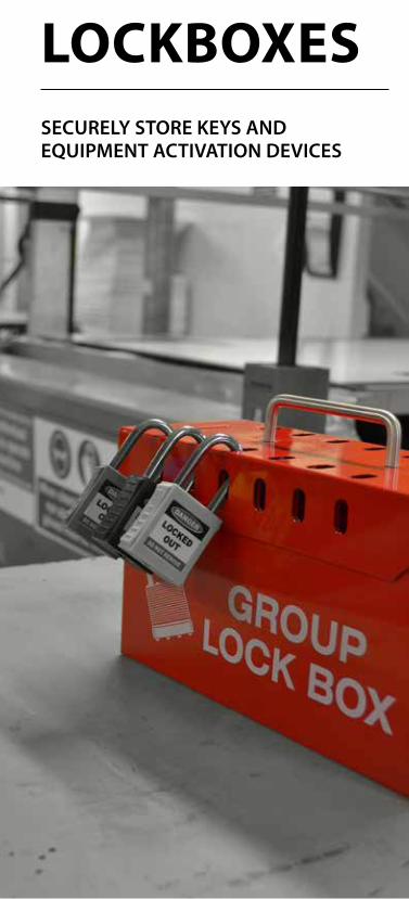
GATE VALVE COVERSLOCKBOXESSECURELY STORE KEYS AND EQUIPMENT ACTIVATION DEVICES
72
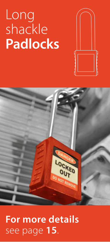
Long shackle Padlocks
For more details see page 15.
73
What are Lockboxes?Provides a safe location to store keys and other activation devices during maintenance or repair.
When to use Lockboxes?Once equipment has been isolated and made safe, any keys or other activating equipment can be stored safety in a lockbox to prevent accidental re-energisation. Multiple padlocks can be affixed to the lock box which all must be removed before access to the contents can be granted.
74
LOCKBOXES
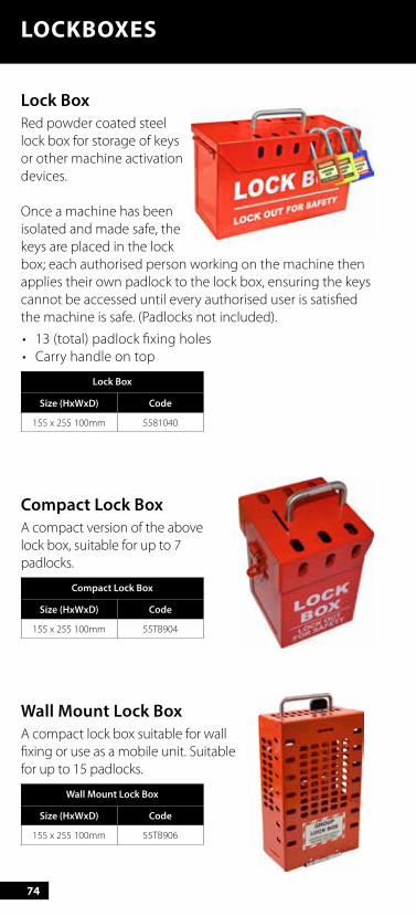
Lock BoxRed powder coated steel lock box for storage of keys or other machine activation devices.
Once a machine has been isolated and made safe, the keys are placed in the lock box; each authorised person working on the machine then applies their own padlock to the lock box, ensuring the keys cannot be accessed until every authorised user is satisfied the machine is safe. (Padlocks not included).
• 13 (total) padlock fixing holes • Carry handle on top
Lock Box
Size (HxWxD) Code
155 x 255 100mm 5581040
Compact Lock BoxA compact version of the above lock box, suitable for up to 7 padlocks.
Compact Lock Box
Size (HxWxD) Code
155 x 255 100mm 55TB904
Wall Mount Lock BoxA compact lock box suitable for wall fixing or use as a mobile unit. Suitable for up to 15 padlocks.
Wall Mount Lock Box
Size (HxWxD) Code
155 x 255 100mm 55TB906
75
GATE VALVE COVERSLOCKOUT STATIONSEASILY STORE AND RETRIEVE LOCKOUT EQUIPMENT
76
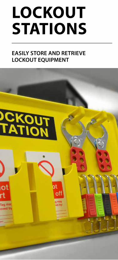
What are Lockout stations?A lockout station provides a platform to store your lockout equipment when not in use.
When to use Lockout stationsA lockout station should be located wherever it is deemed most appropriate for its desired purpose. This could be next to the equipment to be locked out, a maintenance department or a central location. In addition the absence of any equipment is immediately apparent and the missing items can be traced or replenished.
77
GATE VALVE COVERSLOCKOUT STATIONS
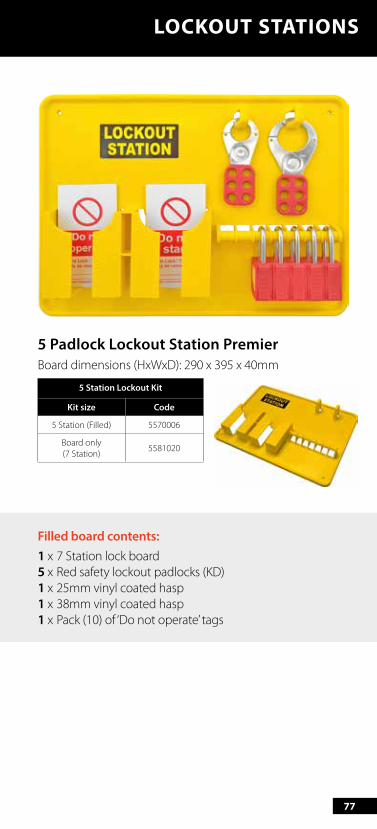
5 Padlock Lockout Station PremierBoard dimensions (HxWxD): 290 x 395 x 40mm
5 Station Lockout Kit
Kit size Code
5 Station (Filled) 5570006
Board only (7 Station)
5581020
Filled board contents:1 x 7 Station lock board5 x Red safety lockout padlocks (KD)1 x 25mm vinyl coated hasp1 x 38mm vinyl coated hasp1 x Pack (10) of ‘Do not operate’ tags
78
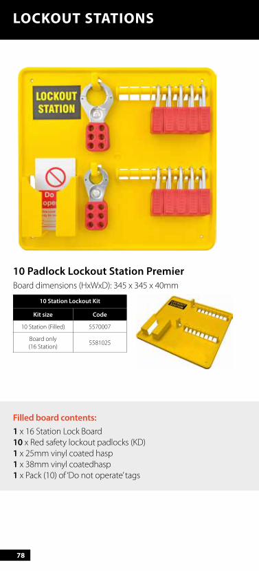
10 Padlock Lockout Station PremierBoard dimensions (HxWxD): 345 x 345 x 40mm
10 Station Lockout Kit
Kit size Code
10 Station (Filled) 5570007
Board only (16 Station)
5581025
LOCKOUT STATIONS
Filled board contents:1 x 16 Station Lock Board10 x Red safety lockout padlocks (KD)1 x 25mm vinyl coated hasp1 x 38mm vinyl coatedhasp1 x Pack (10) of ‘Do not operate’ tags

79
LOCKOUT STATIONS
20 Padlock Lockout Station PremierBoard dimensions (HxWxD): 521 x 320 x 42mm
20 Station Lockout Kit
Kit size Code
20 Station (Filled) 5570008
Board only (20 Station)
5570009
Filled board contents:1 x 20 Station Lock Board20 x Red safety lockout padlocks (KD)1 x 38mm vinyl coated hasp1 x Pack (10) of ‘Do not operate’ tags1 x Pack (10) of ‘Do not start’ tags
80
LOCKOUT STATIONS
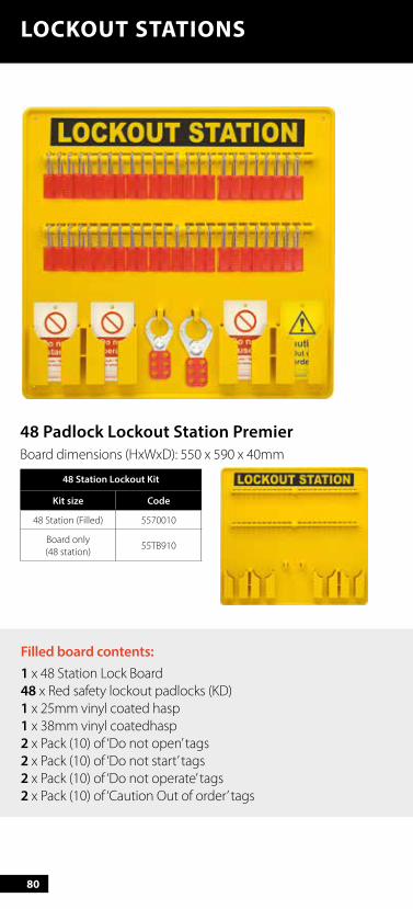
48 Padlock Lockout Station PremierBoard dimensions (HxWxD): 550 x 590 x 40mm
48 Station Lockout Kit
Kit size Code
48 Station (Filled) 5570010
Board only (48 station)
55TB910
Filled board contents:1 x 48 Station Lock Board48 x Red safety lockout padlocks (KD)1 x 25mm vinyl coated hasp1 x 38mm vinyl coatedhasp2 x Pack (10) of ‘Do not open’ tags2 x Pack (10) of ‘Do not start’ tags2 x Pack (10) of ‘Do not operate’ tags2 x Pack (10) of ‘Caution Out of order’ tags

81
Advanced Lockout Station (Small)Engineered from plastic PC, with multiple padlock positions, each position can hold 2 padlocks a hasp, several tagouts or cable ties. Cover supplied enables station to be locked out.
Board dimensions (HxWxD): 406 x 315 x 65mm
Advanced Lockout Station
Code
5570115 station (Filled)
5570114
Board only 5570115
Advanced Lockout Station (Large)Engineered from plastic PC, with multiple board clips to house padlocks, and hasps including built in spaces for tags and tie wraps. Cover supplied enables station to be locked out.
Board dimensions (HxWxD): 558 x 393 x 65mm
Advanced Lockout Station
Code
5570117 station (Filled)
5570116
Board only 5570117
LOCKOUT STATIONS
Filled board contents:4 x Red safety padlocks (KD)1 x 25mm vinyl coated hasp1 x ‘Do not operate’ Tags (10 pk)
Filled board contents:10 x Red safety padlocks (KD)1 x 25mm vinyl coated hasp1 x 38mm vinyl coated hasp1 x ‘Do not operate’ Tags (10 pk)1 x ‘Do not use’ Tags (10 pk)
82
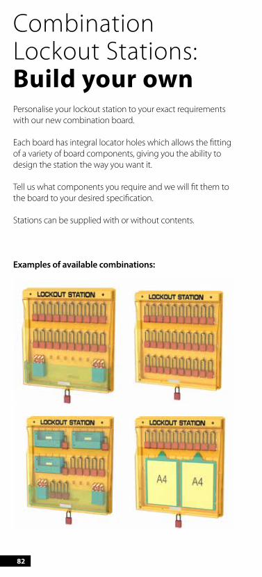
Combination Lockout Stations: Build your ownPersonalise your lockout station to your exact requirements with our new combination board.
Each board has integral locator holes which allows the fitting of a variety of board components, giving you the ability to design the station the way you want it.
Tell us what components you require and we will fit them to the board to your desired specification.
Stations can be supplied with or without contents.
Examples of available combinations:
83
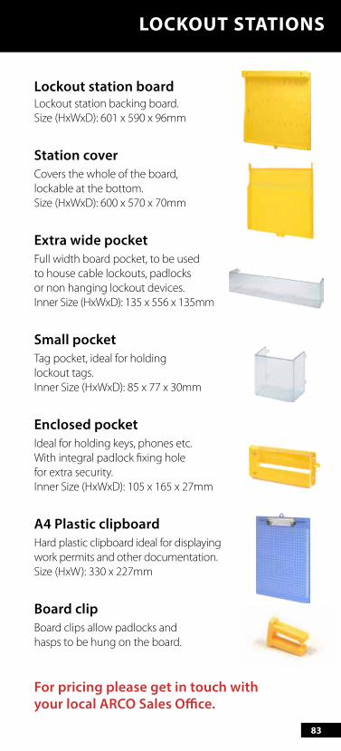
Lockout station boardLockout station backing board. Size (HxWxD): 601 x 590 x 96mm
Station coverCovers the whole of the board, lockable at the bottom. Size (HxWxD): 600 x 570 x 70mm
Extra wide pocketFull width board pocket, to be used to house cable lockouts, padlocks or non hanging lockout devices. Inner Size (HxWxD): 135 x 556 x 135mm
Small pocketTag pocket, ideal for holding lockout tags. Inner Size (HxWxD): 85 x 77 x 30mm
Enclosed pocketIdeal for holding keys, phones etc. With integral padlock fixing hole for extra security. Inner Size (HxWxD): 105 x 165 x 27mm
A4 Plastic clipboardHard plastic clipboard ideal for displaying work permits and other documentation. Size (HxW): 330 x 227mm
Board clipBoard clips allow padlocks and hasps to be hung on the board.
For pricing please get in touch with your local ARCO Sales Office.
LOCKOUT STATIONS

The first step to implementing a LOTO procedure is asking how?
85
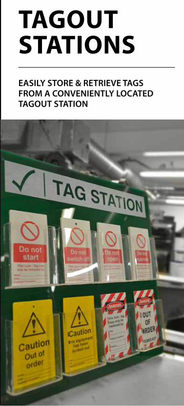
GATE VALVE COVERSTAGOUT STATIONSEASILY STORE & RETRIEVE TAGS FROM A CONVENIENTLY LOCATED TAGOUT STATION
86
TAGOUT STATIONS
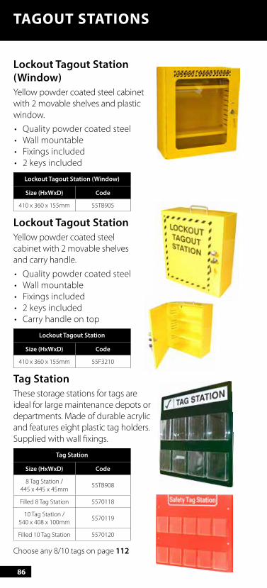
Lockout Tagout Station (Window)Yellow powder coated steel cabinet with 2 movable shelves and plastic window.
• Quality powder coated steel• Wall mountable• Fixings included• 2 keys included
Lockout Tagout Station (Window)
Size (HxWxD) Code
410 x 360 x 155mm 55TB905
Lockout Tagout StationYellow powder coated steel cabinet with 2 movable shelves and carry handle.
• Quality powder coated steel• Wall mountable• Fixings included• 2 keys included• Carry handle on top
Lockout Tagout Station
Size (HxWxD) Code
410 x 360 x 155mm 55F3210
Tag StationThese storage stations for tags are ideal for large maintenance depots or departments. Made of durable acrylic and features eight plastic tag holders.Supplied with wall fixings.
Tag Station
Size (HxWxD) Code
8 Tag Station / 445 x 445 x 45mm
55TB908
Filled 8 Tag Station 5570118
10 Tag Station / 540 x 408 x 100mm
5570119
Filled 10 Tag Station 5570120
Choose any 8/10 tags on page 112
87
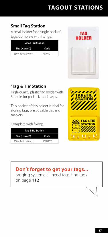
Small Tag StationA small holder for a single pack of tags. Complete with fixings.
Small Tag Station
Size (HxWxD) Code
230 x 130 x 30mm 5570121
‘Tag & Tie’ StationHigh-quality plastic tag holder with 3 hooks for padlocks and hasps.
This pocket of this holder is ideal for storing tags, plastic cable ties and markers.
Complete with fixings.
Tag & Tie Station
Size (HxWxD) Code
250 x 145 x 40mm 55TB907
TAGOUT STATIONS
Don’t forget to get your tags... tagging systems all need tags, find tags on page 112
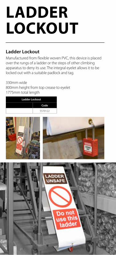
LADDER LOCKOUTLadder LockoutManufactured from flexible woven PVC, this device is placed over the rungs of a ladder or the steps of other climbing apparatus to deny its use. The integral eyelet allows it to be locked out with a suitable padlock and tag.
330mm wide800mm height from top crease to eyelet1775mm total length
Ladder Lockout
Code
5570122
89
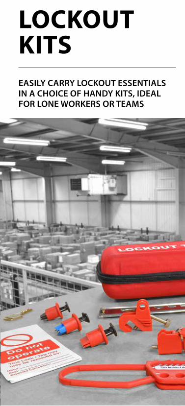
GATE VALVE COVERSLOCKOUT KITSEASILY CARRY LOCKOUT ESSENTIALS IN A CHOICE OF HANDY KITS, IDEAL FOR LONE WORKERS OR TEAMS
90
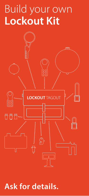
Build your own Lockout Kit
Ask for details.
91
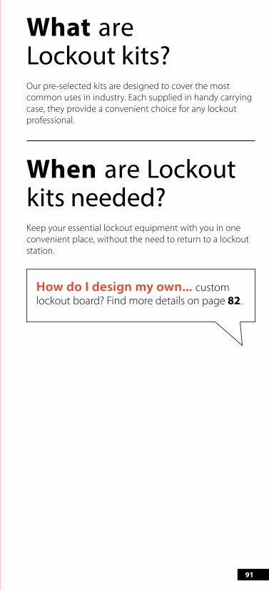
What are Lockout kits? Our pre-selected kits are designed to cover the most common uses in industry. Each supplied in handy carrying case, they provide a convenient choice for any lockout professional.
When are Lockout kits needed? Keep your essential lockout equipment with you in one convenient place, without the need to return to a lockout station.
How do I design my own... custom lockout board? Find more details on page 82.
92
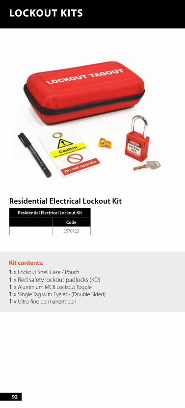
Kit contents:1 x Lockout Shell Case / Pouch1 x Red safety lockout padlocks (KD)1 x Aluminium MCB Lockout Toggle1 x Single Tag with Eyelet - (Double Sided)1 x Ultra-fine permanent pen
LOCKOUT KITS
Residential Electrical Lockout KitResidential Electrical Lockout Kit
Code
5570123
93
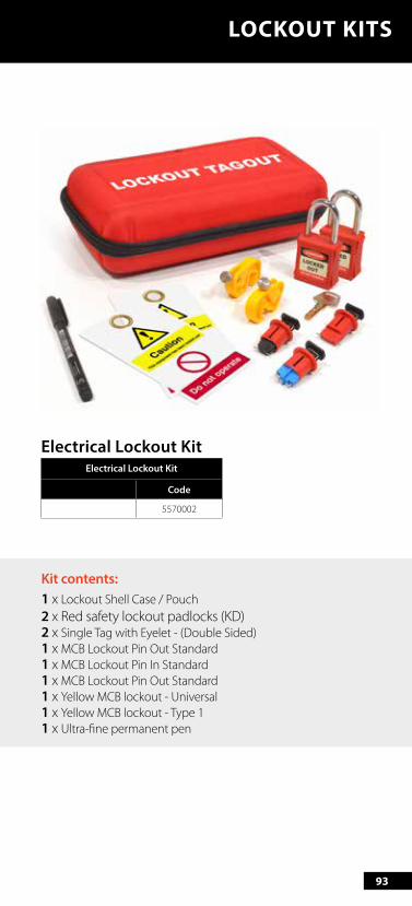
Kit contents:1 x Lockout Shell Case / Pouch2 x Red safety lockout padlocks (KD)2 x Single Tag with Eyelet - (Double Sided)1 x MCB Lockout Pin Out Standard1 x MCB Lockout Pin In Standard1 x MCB Lockout Pin Out Standard1 x Yellow MCB lockout - Universal1 x Yellow MCB lockout - Type 11 x Ultra-fine permanent pen
LOCKOUT KITS
Electrical Lockout KitElectrical Lockout Kit
Code
5570002
94
LOCKOUT KITS
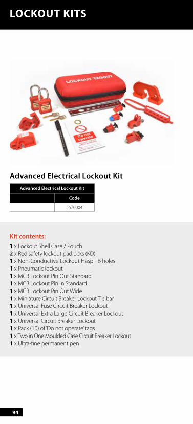
Kit contents:1 x Lockout Shell Case / Pouch2 x Red safety lockout padlocks (KD)1 x Non-Conductive Lockout Hasp - 6 holes1 x Pneumatic lockout 1 x MCB Lockout Pin Out Standard1 x MCB Lockout Pin In Standard1 x MCB Lockout Pin Out Wide1 x Miniature Circuit Breaker Lockout Tie bar1 x Universal Fuse Circuit Breaker Lockout 1 x Universal Extra Large Circuit Breaker Lockout1 x Universal Circuit Breaker Lockout1 x Pack (10) of ‘Do not operate’ tags 1 x Two in One Moulded Case Circuit Breaker Lockout1 x Ultra-fine permanent pen
Advanced Electrical Lockout KitAdvanced Electrical Lockout Kit
Code
5570004

95
LOCKOUT KITS
Kit contents:1 x Lockout Shell Case / Pouch2 x Red safety lockout padlocks (KD)2 x Single Tag with Eyelet - (Double Sided)1 x MCB Lockout Pin Out Standard1 x MCB Lockout Pin In Standard1 x MCB Lockout Pin Out Wide1 x Universal Circuit Breaker Lockout1 x Aluminium MCB Lockout Toggle1 x Multi-purpose Cable Lockout 2.5m1 x Non-Conductive Lockout Hasp - 6 holes 1 x Ultra-fine permanent pen
Maintenance Lockout KitMaintenance Lockout Kit
Code
5570003
96
LOCKOUT KITS
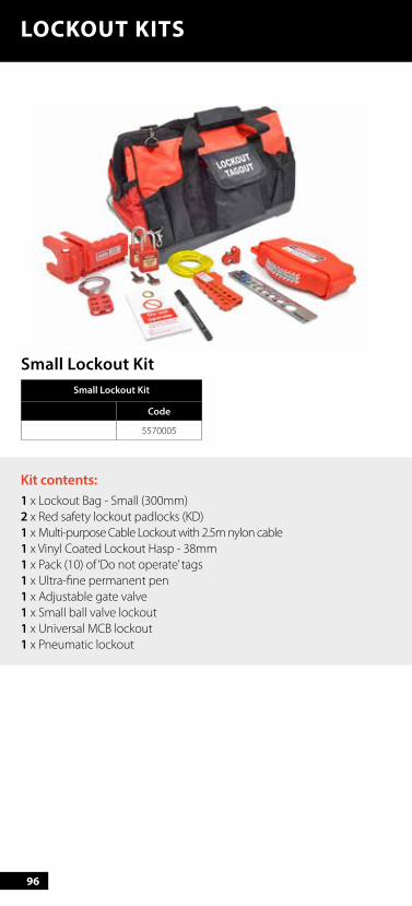
Small Lockout KitSmall Lockout Kit
Code
5570005
Kit contents:1 x Lockout Bag - Small (300mm)2 x Red safety lockout padlocks (KD)1 x Multi-purpose Cable Lockout with 2.5m nylon cable1 x Vinyl Coated Lockout Hasp - 38mm1 x Pack (10) of ‘Do not operate’ tags 1 x Ultra-fine permanent pen 1 x Adjustable gate valve 1 x Small ball valve lockout1 x Universal MCB lockout 1 x Pneumatic lockout
97
LOCKOUT KITS
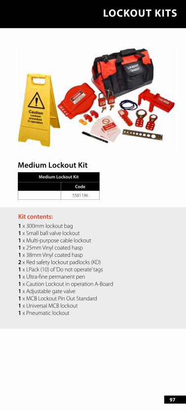
Medium Lockout KitMedium Lockout Kit
Code
5581196
Kit contents:1 x 300mm lockout bag1 x Small ball valve lockout1 x Multi-purpose cable lockout1 x 25mm Vinyl coated hasp1 x 38mm Vinyl coated hasp 2 x Red safety lockout padlocks (KD)1 x LPack (10) of ‘Do not operate’ tags 1 x Ultra-fine permanent pen 1 x Caution Lockout in operation A-Board 1 x Adjustable gate valve 1 x MCB Lockout Pin Out Standard 1 x Universal MCB lockout 1 x Pneumatic lockout

98
LOCKOUT KITS
Large Lockout KitLarge Lockout Kit
Code
5581197
Kit contents:1 x 400mm lockout bag1 x Small ball valve lockout1 x Large ball valve lockout 2 x Multi-purpose cable lockout 2 x 25mm Vinyl coated hasp2 x 38mm Vinyl coated hasp 6 x Red safety lockout padlocks (KD)3 x Pack (10) of ‘Do not operate’ tags2 x Ultra-fine permanent pen 1 x 25-63.5mm Gate valve lockout 1 x 63.5-127mm Gate valve lockout 1 x 127-165mm Gate valve lockout 1 x Caution Lockout in operation A-Board 1 x Large plug / Pneumatic lockout1 x MCB Lockout Pin Out Standard1 x MCB Lockout Pin In Standard1 x MCB Lockout Pin Out Wide2 x Universal MCB lockout 1 x Pneumatic lockout 1 x 3-phase dial lockout
99
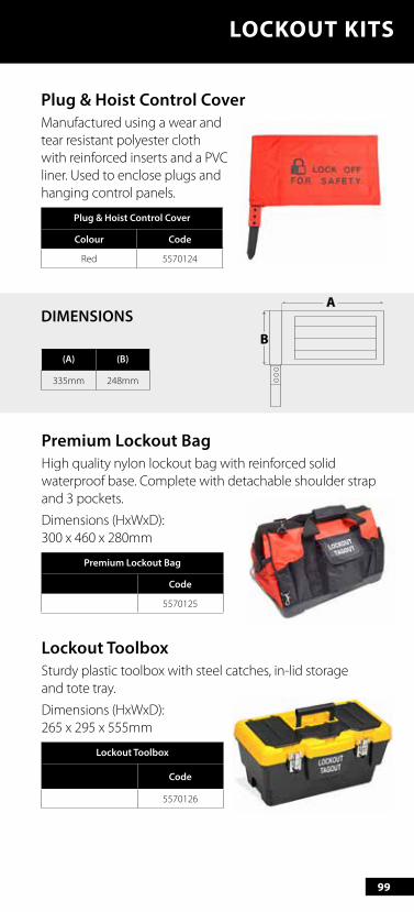
Plug & Hoist Control CoverManufactured using a wear and tear resistant polyester cloth with reinforced inserts and a PVC liner. Used to enclose plugs and hanging control panels.
Plug & Hoist Control Cover
Colour Code
Red 5570124
LOCKOUT KITS
(A) (B)
335mm 248mm
A
B
DIMENSIONS
Premium Lockout BagHigh quality nylon lockout bag with reinforced solid waterproof base. Complete with detachable shoulder strap and 3 pockets.
Dimensions (HxWxD): 300 x 460 x 280mm
Premium Lockout Bag
Code
5570125
Lockout ToolboxSturdy plastic toolbox with steel catches, in-lid storage and tote tray.
Dimensions (HxWxD): 265 x 295 x 555mm
Lockout Toolbox
Code
5570126
100
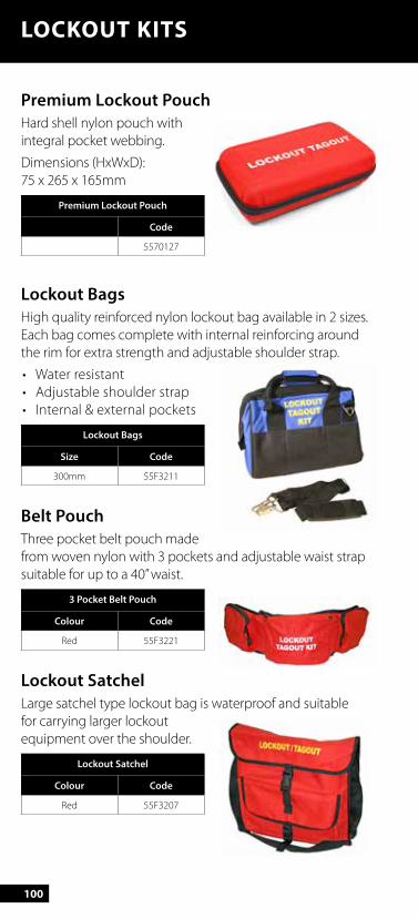
Premium Lockout PouchHard shell nylon pouch with integral pocket webbing.
Dimensions (HxWxD): 75 x 265 x 165mm
Premium Lockout Pouch
Code
5570127
Lockout BagsHigh quality reinforced nylon lockout bag available in 2 sizes.Each bag comes complete with internal reinforcing around the rim for extra strength and adjustable shoulder strap.
• Water resistant• Adjustable shoulder strap• Internal & external pockets
Lockout Bags
Size Code
300mm 55F3211
Belt PouchThree pocket belt pouch made from woven nylon with 3 pockets and adjustable waist strap suitable for up to a 40” waist.
3 Pocket Belt Pouch
Colour Code
Red 55F3221
Lockout SatchelLarge satchel type lockout bag is waterproof and suitable for carrying larger lockout equipment over the shoulder.
Lockout Satchel
Colour Code
Red 55F3207
LOCKOUT KITS
101
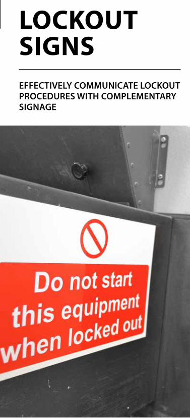
LOCKOUT SIGNSEFFECTIVELY COMMUNICATE LOCKOUT PROCEDURES WITH COMPLEMENTARY SIGNAGE

102
Custom Signs
Customise your site signage with your own branding.
Ask for details.
103
What are Lockout signs? Lockout signs are designed to notify employees of lockout procedures, equipment positioning within the work environment as well as highlighting lockout points and lockout stations.
When are Lockout signs needed? Lockout signs are needed when lockout stations and equipment are being used. By using lockout signs, you ensure that all employees are aware of the procedures and actions required to work in a safe environment.
Do you need...a Lockout Station or a Lockout Kit? For more details on Lockout Stations visit page 76. And for more details on Lockout Kits visit page 91.
104
LOCKOUT SIGNS
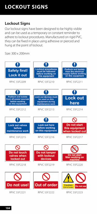
Lockout SignsOur lockout signs have been designed to be highly visible and can be used as a temporary or constant reminder to adhere to lockout procedures. Manufactured on rigid PVC, they can be fixed in place using adhesive or pierced and hung at the point of lockout.
Size: 300 x 200mm
RPVC 55F2209
RPVC 55F2215
RPVC 55F2212
RPVC 55F2218
RPVC 55F2221
RPVC 55F2210
RPVC 55F2216
RPVC 55F2213
RPVC 55F2219
RPVC 55F2222
RPVC 55F2211
RPVC 55F2217
RPVC 55F2214
RPVC 55F2220
RPVC 55F2223

105
LOCKOUT SIGNS
Magnetic Lockout SignsPrinted on a quality white faced magnetic substrate, these signs are easy to attach and provide clear and important messages at the point of isolation.
Custom designs available on request.
Size: 225 x 150mm
RPVC 55F2224
RPVC 55F2230
MAG 55F2233
MAG 55F2235
RPVC 55F2227
RPVC 55F2225
RPVC 55F2231
MAG 55F2234
MAG 55F2236
RPVC 55F2228
RPVC 55F2226
RPVC 55F2232
RPVC 55F2229
106
LOCKOUT SIGNS
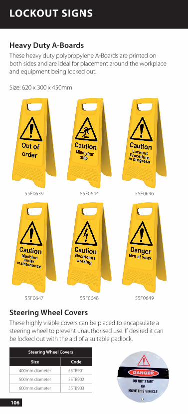
Heavy Duty A-BoardsThese heavy duty polypropylene A-Boards are printed on both sides and are ideal for placement around the workplace and equipment being locked out.
Size: 620 x 300 x 450mm
Steering Wheel CoversThese highly visible covers can be placed to encapsulate a steering wheel to prevent unauthorised use. If desired it can be locked out with the aid of a suitable padlock.
Steering Wheel Covers
Size Code
400mm diameter 55TB901
500mm diameter 55TB902
600mm diameter 55TB903
55F0639
55F0647
55F0644
55F0648
55F0646
55F0649
107
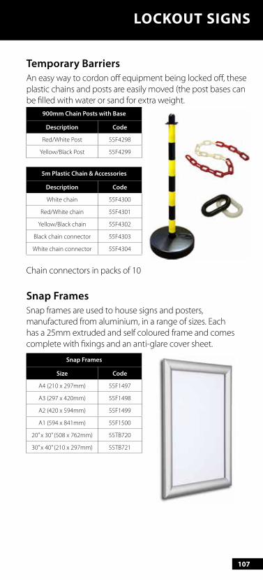
Temporary BarriersAn easy way to cordon off equipment being locked off, these plastic chains and posts are easily moved (the post bases can be filled with water or sand for extra weight.
900mm Chain Posts with Base
Description Code
Red/White Post 55F4298
Yellow/Black Post 55F4299
5m Plastic Chain & Accessories
Description Code
White chain 55F4300
Red/White chain 55F4301
Yellow/Black chain 55F4302
Black chain connector 55F4303
White chain connector 55F4304
Chain connectors in packs of 10
Snap FramesSnap frames are used to house signs and posters, manufactured from aluminium, in a range of sizes. Each has a 25mm extruded and self coloured frame and comes complete with fixings and an anti-glare cover sheet.
Snap Frames
Size Code
A4 (210 x 297mm) 55F1497
A3 (297 x 420mm) 55F1498
A2 (420 x 594mm) 55F1499
A1 (594 x 841mm) 55F1500
20” x 30” (508 x 762mm) 55TB720
30” x 40” (210 x 297mm) 55TB721
LOCKOUT SIGNS

Simple safety improvements can make the greatest significance.
109
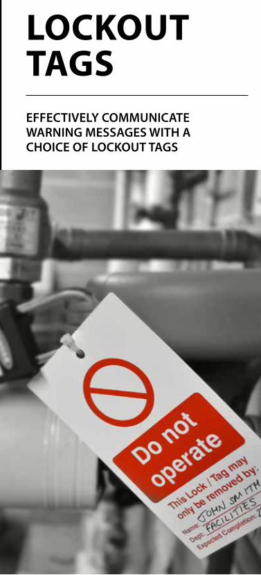
GATE VALVE COVERSLOCKOUT TAGSEFFECTIVELY COMMUNICATE WARNING MESSAGES WITH A CHOICE OF LOCKOUT TAGS
110
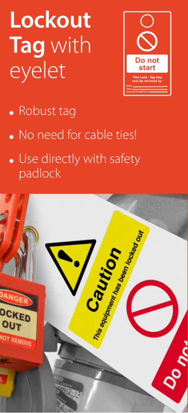
Lockout Tag with eyelet
Robust tag
No need for cable ties!
Use directly with safety padlock

111
What are Lockout Tags? Lockout Tags are used to explain why a device has been locked out. Tags are designed to withstand maximum exposure to its intended placement and retain message visibility to ensure that it is not removed before repair and maintenance is complete.
When are Lockout Tags needed? Lockout Tags are needed every time a Lockout Tagout device is locked out for repair or maintenance.
Remember Padlocks and Tags should always be used...
Find Padlocks on page 14 and find Tags on page 112
112
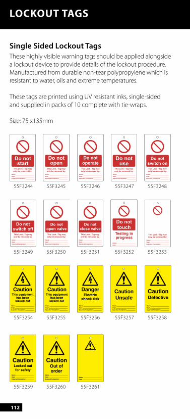
LOCKOUT TAGS
Single Sided Lockout Tags These highly visible warning tags should be applied alongside a lockout device to provide details of the lockout procedure. Manufactured from durable non-tear polypropylene which is resistant to water, oils and extreme temperatures.
These tags are printed using UV resistant inks, single-sided and supplied in packs of 10 complete with tie-wraps.
Size: 75 x135mm
55F3244
55F3249
55F3254
55F3259
55F3245
55F3250
55F3255
55F3260
55F3246
55F3251
55F3256
55F3261
55F3247
55F3252
55F3257
55F3248
55F3253
55F3258
Caution
Name:
Dept:
Expected Completion:
Locked out
for safety
Caution
Name:
Dept:
Expected Completion:
Out oforder
Name:
Date:
This Lock / Tag may
only be removed by:
Name:
Dept:
Expected Completion:
Do notstart
This Lock / Tag may
only be removed by:
Name:
Dept:
Expected Completion:
Do notswitch off
Caution
Name:
Dept:
Expected Completion:
This equipmenthas been
locked out
This Lock / Tag may
only be removed by:
Do notopen
Name:
Dept:
Expected Completion:
This Lock / Tag may
only be removed by:
Name:
Dept:
Expected Completion:
Do notopen valve
Caution
Name:
Dept:
Expected Completion:
This equipmenthas been
locked out
This Lock / Tag may
only be removed by:
Name:
Dept:
Expected Completion:
This Lock / Tag may
only be removed by:
Name:
Dept:
Expected Completion:
Do notclose valve
Danger
Name:
Dept:
Expected Completion:
Electricshock risk
This Lock / Tag may
only be removed by:
Name:
Dept:
Expected Completion:
Do notuse
Testing inprogress
Name:
Date:
Do nottouch
Caution
Unsafe
Name:
Dept:
Expected Completion:
This Lock / Tag may
only be removed by:
Name:
Dept:
Expected Completion:
Do notswitch on
This Lock / Tag may
only be removed by:
Name:
Dept:
Expected Completion:
CautionDefective
Name:
Dept:
Expected Completion:

113
LOCKOUT TAGS
Double Sided Lockout TagsThese tags are printed on both sides with the details displayed below. Supplied in packs of 10 complete with tie-wraps.
Size: 75 x 135mm
5581050
55F3223
55F3229
55F3233 REVERSE55F3233
55F3227
5581051
55F3224
55F3230
55F3228
5581052
55F3225
55F3231
55F3222
55F3226
55F3232
FRONT REVERSE
This Lock / Tag may
only be removed by:
Name:
Dept:
Expected Completion:
Do notswitch on
Caution
Name:
Dept:
Expected Completion:
This equipmenthas been
locked out
Caution
Name:
Dept:
Expected Completion:
Out oforder
Testing inprogress
Name:
Date:
Do nottouch
This Lock / Tag may
only be removed by:
Name:
Dept:
Expected Completion:
Do notstart
This Lock / Tag may
only be removed by:
Name:
Dept:
Expected Completion:
Do notswitch off
Caution
Name:
Dept:
Expected Completion:
This equipmenthas been
locked out
This Lock / Tag may
only be removed by:
Name:
Dept:
Expected Completion:
This Lock / Tag may
only be removed by:
Do notopen
Name:
Dept:
Expected Completion:
This Lock / Tag may
only be removed by:
Name:
Dept:
Expected Completion:
Do notopen valve
Caution
Name:
Dept:
Expected Completion:
Locked out
for safety
This Lock / Tag may
only be removed by:
Name:
Dept:
Expected Completion:
Do notuse
This Lock / Tag may
only be removed by:
Name:
Dept:
Expected Completion:
Do notclose valve
Caution
Unsafe
Name:
Dept:
Expected Completion:
114
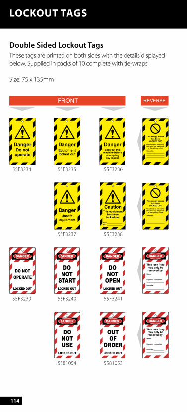
LOCKOUT TAGS
Double Sided Lockout TagsThese tags are printed on both sides with the details displayed below. Supplied in packs of 10 complete with tie-wraps.
Size: 75 x 135mm
55F3234
55F3239
55F3235
55F3240
55F3237
5581054
55F3236
55F3241
55F3238
5581053
FRONT REVERSE
DangerUnsafe
equipment
LOCKED OUT
DO
NOT
USE
CautionThis equipment
has beenlocked out
Name:
Date:
LOCKED OUT
OUT
OF
ORDER
DangerDo notoperate
DO NOT
OPERATE
LOCKED OUT
DangerEquipmentlocked out
LOCKED OUT
DO
NOT
START
DangerLock out this
machine beforeattemptingany repairs
LOCKED OUT
DO
NOT
OPEN
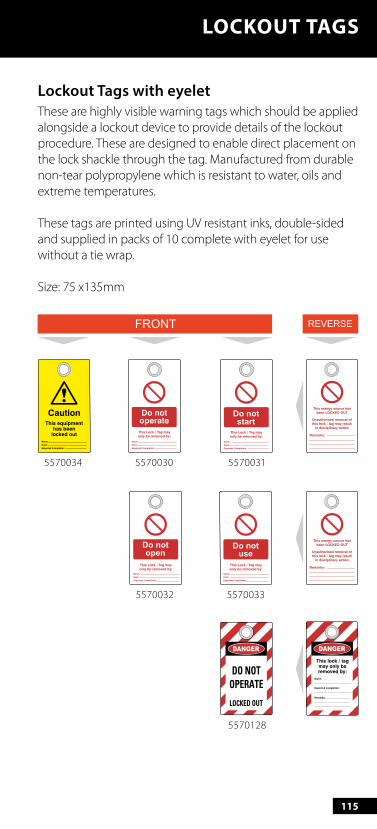
115
5570034
5570032
5570030
5570033
5570031
5570128
FRONT REVERSE
LOCKOUT TAGS
Lockout Tags with eyeletThese are highly visible warning tags which should be applied alongside a lockout device to provide details of the lockout procedure. These are designed to enable direct placement on the lock shackle through the tag. Manufactured from durable non-tear polypropylene which is resistant to water, oils and extreme temperatures.
These tags are printed using UV resistant inks, double-sided and supplied in packs of 10 complete with eyelet for use without a tie wrap.
Size: 75 x135mm
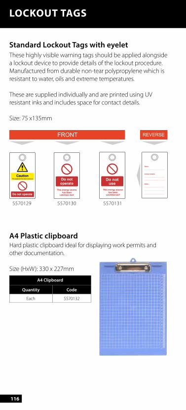
116
LOCKOUT TAGS
Standard Lockout Tags with eyeletThese highly visible warning tags should be applied alongside a lockout device to provide details of the lockout procedure. Manufactured from durable non-tear polypropylene which is resistant to water, oils and extreme temperatures.
These are supplied individually and are printed using UV resistant inks and includes space for contact details.
Size: 75 x135mm
A4 Plastic clipboardHard plastic clipboard ideal for displaying work permits and other documentation. Size (HxW): 330 x 227mm
A4 Clipboard
Quantity Code
Each 5570132
5570129 5570130 5570131
FRONT REVERSE
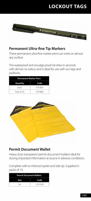
117
Permanent Ultra-fine Tip MarkersThese permanent ultra-fine marker pens can write on almost any surface.
The waterproof and smudge proof ink dries in seconds with almost no odour, and is ideal for use with our tags and padlocks.
Permanent Marker Pens
Quantity Code
Each 55F3865
Pack of 10 55F3866
Permit Document WalletHeavy duty transparent permit document holders ideal for storing important information at source in adverse conditions.
Complete with re-inforced eyelet and side zip. Supplied in packs of 10.
Permit Document Wallets
Size Code
A4 5519100
LOCKOUT TAGS
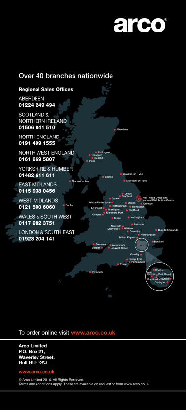
Over 40 branches nationwide
Regional Sales Offices
ABERDEEN 01224 249 494
SCOTLAND & NORTHERN IRELAND 01506 841 510
NORTH ENGLAND 0191 499 1555
NORTH WEST ENGLAND 0161 869 5807
YORKSHIRE & HUMBER 01482 611 611
EAST MIDLANDS 0115 938 0456
WEST MIDLANDS 0121 500 6060
WALES & SOUTH WEST 0117 982 3751
LONDON & SOUTH EAST 01923 204 141
To order online visit www.arco.co.uk
Arco LimitedP.O. Box 21,Waverley Street,Hull HU1 2SJ
www.arco.co.uk
© Arco Limited 2016. All Rights Reserved. Terms and conditions apply. These are available on request or from www.arco.co.uk