a decade of prototype displays - applied physics laboratory · a decade of prototype displays...
TRANSCRIPT
428 JOHNSHOPKINSAPLTECHNICALDIGEST,VOLUME22,NUMBER4(2001)
D. M. SUNDAY and C. J. DUHON
W
A Decade of Prototype Displays
Daniel M. Sunday and Christopher J. Duhon
edescribeanevolutionofdisplayprototypesthatAPLdevelopedforAegisandtheCooperativeEngagementCapability.Theworkspannedmorethanadecadefromthelate1980sto2000.ManyoftheideasandsoftwareproducedwereincorporatedintotheNavy’smostsignificantcombatsystemdisplays(AegisDisplaySystem,AdvancedCombatDirectionSystem,andShipSelf-DefenseSystem)aswellasnumerousengineeringdis-plays.Thisarticlerecountstheworkanddescribessomeofthedisplayfeaturesalongwithsignificantaspectsofthedisplayarchitecture.
INTRODUCTIONFromthe late1980s through2000,APLdeveloped
prototype combat system displays. These prototypeshavenowtransitionedtoindustryandarebeingusedasthefoundationforthemostsignificantNavyproductioncombat display systems, including Lockheed Martin’sAegis Display System (ADS), Raytheon’s AdvancedCombatDirectionSystem(ACDS)commandstation,Raytheon’sShipSelf-DefenseSystem(SSDS)display,andtheNavalAirSystemsCommand’sE-2CAdvancedControl Indicator Set (ACIS) display. In all cases,APLprovidedagenericdisplayenginealongwithasoft-waretoolkitofdisplaycomponentsthatwascollectivelyreferredtoastheCommonDisplayKernel(CDK).Ven-dors of platform-specific display systems then tailoredandenhancedCDKtomeettheirmissionrequirements.In addition to these production displays, CDK wasusedinnumerousengineeringandsimulationdisplays,such as the Battle Force Tactical Trainer and APL’sCooperative Engagement Capability (CEC) engineer-ingdisplays.
InthisarticlewefirstreviewtheevolutionoftheAPLprototype displays from the mid-1980s, then describethe functionalityprovided inthefinalbuildsofCDK,andgiveashortoverviewofitsarchitecture.
BACKGROUNDAPL’s display prototype work was initiated as the
CommandSupportAt-SeaExperiment(CS@SE),whichevolved through four phases. In 1987, the kickoffPhase I was led by Jennings Willey as a follow-on tohis seminal paper1 on advanced graphics techniques.PhaseIprimarilyinvestigatedtheuseofcolorandareafillforinformationdiscriminationinNavycombatdis-plays.ThePhaseIprototypesunderwentat-seatestingaboardtheAegiscruisersUSS Ticonderoga (CG47)andUSSYorktown (CG48).
In 1988–1989, Phase II, led by Dave Buscher,extended the experiment to include numerous newfeatures (e.g., enhanced geographic displays) and
JOHNSHOPKINSAPLTECHNICALDIGEST,VOLUME22,NUMBER4(2001) 429
A DECADE OF PROTOTYPE DISPLAYS
combined real-time sensor and non-real-time over-the-horizon tracks in the same display.2 The PhaseIIprototypeswereevaluatedaboardtheAegiscruiserUSS Leyte Gulf (CG55)andthecarrierUSS America (CV66).ThePhaseIIdisplayalsohadtwoimportantspin-offs: the first auto-identification (auto-ID) dis-playsbeingdevelopedbyRogerSumeyandafirstCECengineeringdisplaydevelopedbyJohnPedenandDanSunday.
In 1989–1991, Phase III, led by Conrad Grant,further investigated the fusion of real-time sensorandnon-real-timeover-the-horizontrackinformationwith a prototype network track server that imple-mented a multi-hypothesis correlation algorithm.3ThePhaseIIIprototypeswereevaluatedaboardUSSLeyte GulfandthecarrierUSSRoosevelt(CVN71),andwereusedonthoseshipsduringDesertStorminthePersianGulf.
In 1991–1993, the final Phase IV, led by DanSunday, further evolved CS@SE into a network-centricsystemwithmultipleoperatorstationsandmul-tipleserversfortrackfusion,DefenseMappingAgencyandNational ImageryandMappingAgency (NIMA)geographicdatabases,andanetworkarchive-playbackserver(NAPS)ofmission-recordedscenarios.Newideasfor the Human–Machine Interface (HMI) GraphicalUser Interface (GUI)were exploredusingXWindowsandtheMotifGUItoolkit,andCECtrackdatabecameanotherreal-timeinput.ThePhaseIVprototypeswere
ThreatEvaluationandWeaponsAssignmentdisplays,alineageitshareswiththeAreaAirDefenseCoordinator(AADC),tobedescribedinthenextissueoftheDigest.Leadpersonnelforthismultiplicityofprojectsoverthefollowing years included Conrad Grant, Dan Sunday,EricConn,DonDavis,ChrisDuhon,PaulMcMullin,andDaveNesbitt.
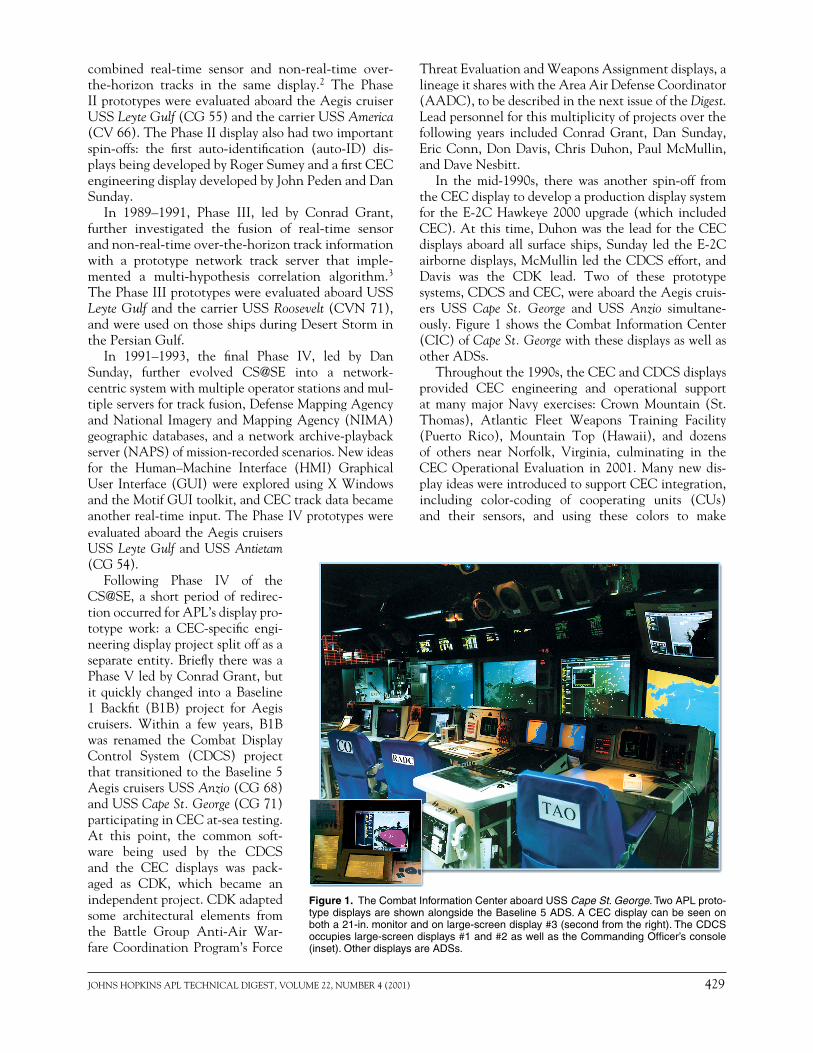
In the mid-1990s, there was another spin-off fromtheCECdisplaytodevelopaproductiondisplaysystemfor theE-2CHawkeye2000upgrade (which includedCEC).Atthistime,DuhonwastheleadfortheCECdisplaysaboardall surface ships,Sunday led theE-2Cairbornedisplays,McMullinledtheCDCSeffort,andDavis was the CDK lead. Two of these prototypesystems,CDCSandCEC,wereaboardtheAegiscruis-ers USS Cape St. George and USS Anzio simultane-ously.Figure1showstheCombatInformationCenter(CIC)ofCape St. GeorgewiththesedisplaysaswellasotherADSs.
Throughoutthe1990s,theCECandCDCSdisplaysprovided CEC engineering and operational supportat many major Navy exercises: Crown Mountain (St.Thomas), Atlantic Fleet Weapons Training Facility(Puerto Rico), Mountain Top (Hawaii), and dozensof others near Norfolk, Virginia, culminating in theCECOperationalEvaluation in2001.Manynewdis-playideaswereintroducedtosupportCECintegration,including color-coding of cooperating units (CUs)and their sensors, and using these colors to make
Figure 1. The Combat Information Center aboard USS Cape St. George. Two APL proto-type displays are shown alongside the Baseline 5 ADS. A CEC display can be seen on both a 21-in. monitor and on large-screen display #3 (second from the right). The CDCS occupies large-screen displays #1 and #2 as well as the Commanding Officer’s console (inset). Other displays are ADSs.
evaluatedaboardtheAegiscruisersUSSLeyte Gulf andUSSAntietam(CG54).
Following Phase IV of theCS@SE, a short period of redirec-tionoccurredforAPL’sdisplaypro-totype work: a CEC-specific engi-neeringdisplayprojectsplitoffasaseparateentity.BrieflytherewasaPhaseVledbyConradGrant,butitquicklychanged intoaBaseline1 Backfit (B1B) project for Aegiscruisers. Within a few years, B1Bwas renamed the Combat DisplayControl System (CDCS) projectthattransitionedtotheBaseline5AegiscruisersUSSAnzio(CG68)andUSSCape St. George(CG71)participatinginCECat-seatesting.At this point, the common soft-ware being used by the CDCSand the CEC displays was pack-aged as CDK, which became anindependentproject.CDKadaptedsome architectural elements fromthe Battle Group Anti-Air War-fareCoordinationProgram’sForce
430 JOHNSHOPKINSAPLTECHNICALDIGEST,VOLUME22,NUMBER4(2001)
D. M. SUNDAY and C. J. DUHON
associationsinthedisplays.Inparticular,engagementsand their providers were color-coded by CU, as werecolored-dot history trails of CU sensor events behindeach track. In addition, new tactical decision aids(TDAs), such as the Radar Masking tool and theCU Position Planner, were developed for theCECdisplays.Thesedisplayswere aboardUSSEisen-hower(CVN69)duringits1994Mediterraneandeploy-ment,whichalso included theCDCSaboard the twoAegiscruisers.
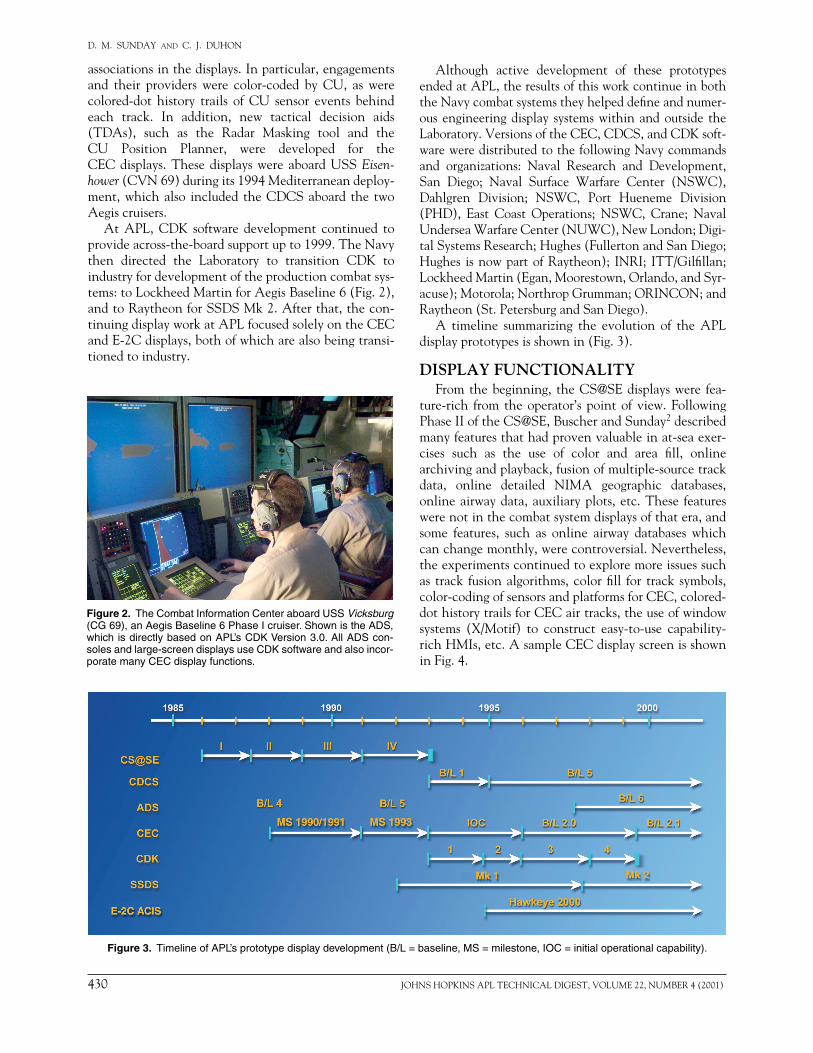
At APL, CDK software development continued toprovideacross-the-boardsupportupto1999.TheNavythen directed the Laboratory to transition CDK toindustryfordevelopmentoftheproductioncombatsys-tems:toLockheedMartinforAegisBaseline6(Fig.2),andtoRaytheonforSSDSMk2.Afterthat,thecon-tinuingdisplayworkatAPLfocusedsolelyontheCECandE-2Cdisplays,bothofwhicharealsobeingtransi-tionedtoindustry.
Although active development of these prototypesendedatAPL,theresultsofthisworkcontinueinboththeNavycombatsystemstheyhelpeddefineandnumer-ous engineeringdisplay systemswithinandoutside theLaboratory.VersionsoftheCEC,CDCS,andCDKsoft-wareweredistributedtothefollowingNavycommandsand organizations: Naval Research and Development,San Diego; Naval Surface Warfare Center (NSWC),Dahlgren Division; NSWC, Port Hueneme Division(PHD), East Coast Operations; NSWC, Crane; NavalUnderseaWarfareCenter(NUWC),NewLondon;Digi-talSystemsResearch;Hughes(FullertonandSanDiego;Hughes isnowpartofRaytheon); INRI; ITT/Gilfillan;LockheedMartin(Egan,Moorestown,Orlando,andSyr-acuse);Motorola;NorthropGrumman;ORINCON;andRaytheon(St.PetersburgandSanDiego).
A timeline summarizing the evolution of the APLdisplayprototypesisshownin(Fig.3).
DISPLAY FUNCTIONALITYFromthebeginning, theCS@SEdisplayswere fea-
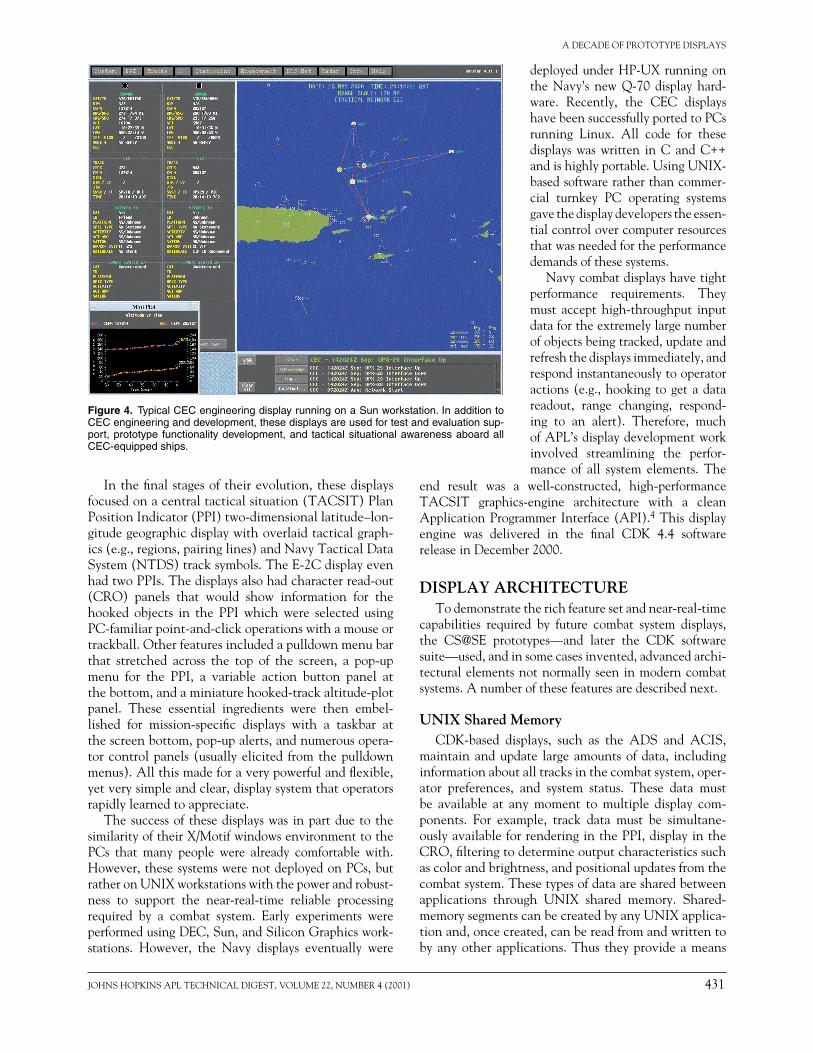
ture-rich from theoperator’s pointofview.FollowingPhaseIIoftheCS@SE,BuscherandSunday2describedmanyfeaturesthathadprovenvaluableinat-seaexer-cises such as the use of color and area fill, onlinearchivingandplayback,fusionofmultiple-sourcetrackdata, online detailed NIMA geographic databases,onlineairwaydata,auxiliaryplots,etc.These featureswerenotinthecombatsystemdisplaysofthatera,andsome features, such as online airway databases whichcanchangemonthly,werecontroversial.Nevertheless,theexperimentscontinuedtoexploremoreissuessuchas track fusionalgorithms,colorfill for track symbols,color-codingofsensorsandplatformsforCEC,colored-dothistorytrailsforCECairtracks,theuseofwindowsystems (X/Motif) to construct easy-to-use capability-richHMIs,etc.AsampleCECdisplayscreenisshowninFig.4.
Figure 2. The Combat Information Center aboard USS Vicksburg (CG 69), an Aegis Baseline 6 Phase I cruiser. Shown is the ADS, which is directly based on APL’s CDK Version 3.0. All ADS con-soles and large-screen displays use CDK software and also incor-porate many CEC display functions.
Figure 3. Timeline of APL’s prototype display development (B/L = baseline, MS = milestone, IOC = initial operational capability).
JOHNSHOPKINSAPLTECHNICALDIGEST,VOLUME22,NUMBER4(2001) 431
A DECADE OF PROTOTYPE DISPLAYS
Inthefinalstagesoftheirevolution,thesedisplaysfocusedonacentraltacticalsituation(TACSIT)PlanPositionIndicator(PPI)two-dimensionallatitude–lon-gitudegeographicdisplaywithoverlaidtacticalgraph-ics(e.g.,regions,pairinglines)andNavyTacticalDataSystem(NTDS)tracksymbols.TheE-2CdisplayevenhadtwoPPIs.Thedisplaysalsohadcharacterread-out(CRO) panels that would show information for thehooked objects in the PPI which were selected usingPC-familiarpoint-and-clickoperationswithamouseortrackball.Otherfeaturesincludedapulldownmenubarthat stretched across the top of the screen, a pop-upmenu for the PPI, a variable action button panel atthebottom,andaminiaturehooked-trackaltitude-plotpanel. These essential ingredients were then embel-lished for mission-specific displays with a taskbar atthescreenbottom,pop-upalerts,andnumerousopera-torcontrolpanels(usuallyelicited fromthepulldownmenus).Allthismadeforaverypowerfulandflexible,yetverysimpleandclear,displaysystemthatoperatorsrapidlylearnedtoappreciate.
The successof thesedisplayswas inpartdue to thesimilarityoftheirX/MotifwindowsenvironmenttothePCs that many people were already comfortable with.However,thesesystemswerenotdeployedonPCs,butratheronUNIXworkstationswiththepowerandrobust-ness to support the near-real-time reliable processingrequired by a combat system. Early experiments wereperformedusingDEC,Sun,andSiliconGraphicswork-stations. However, the Navy displays eventually were
end result was a well-constructed, high-performanceTACSIT graphics-engine architecture with a cleanApplicationProgrammerInterface(API).4Thisdisplayengine was delivered in the final CDK 4.4 softwarereleaseinDecember2000.
DISPLAY ARCHITECTURETodemonstratetherichfeaturesetandnear-real-time
capabilities required by future combat system displays,the CS@SE prototypes—and later the CDK softwaresuite—used,andinsomecasesinvented,advancedarchi-tecturalelementsnotnormallyseeninmoderncombatsystems.Anumberofthesefeaturesaredescribednext.
UNIX Shared MemoryCDK-based displays, such as the ADS and ACIS,
maintainandupdate largeamountsofdata, includinginformationaboutalltracksinthecombatsystem,oper-ator preferences, and system status. These data mustbe available at any moment to multiple display com-ponents. For example, track data must be simultane-ouslyavailableforrenderinginthePPI,displayintheCRO,filteringtodetermineoutputcharacteristicssuchascolorandbrightness,andpositionalupdatesfromthecombatsystem.Thesetypesofdataaresharedbetweenapplications through UNIX shared memory. Shared-memorysegmentscanbecreatedbyanyUNIXapplica-tionand,oncecreated,canbereadfromandwrittentobyanyotherapplications.Thus theyprovideameans
Figure 4. Typical CEC engineering display running on a Sun workstation. In addition to CEC engineering and development, these displays are used for test and evaluation sup-port, prototype functionality development, and tactical situational awareness aboard all CEC-equipped ships.
deployedunderHP-UXrunningonthe Navy’s new Q-70 display hard-ware. Recently, the CEC displayshavebeensuccessfullyportedtoPCsrunning Linux. All code for thesedisplays was written in C and C++andishighlyportable.UsingUNIX-basedsoftwareratherthancommer-cial turnkey PC operating systemsgavethedisplaydeveloperstheessen-tialcontrolovercomputerresourcesthatwasneededfortheperformancedemandsofthesesystems.
Navycombatdisplayshavetightperformance requirements. Theymust accept high-throughput inputdatafortheextremelylargenumberofobjectsbeingtracked,updateandrefreshthedisplaysimmediately,andrespondinstantaneouslytooperatoractions(e.g.,hooking togetadatareadout, range changing, respond-ing to an alert). Therefore, muchofAPL’sdisplaydevelopmentworkinvolved streamlining the perfor-mance of all system elements. The
432 JOHNSHOPKINSAPLTECHNICALDIGEST,VOLUME22,NUMBER4(2001)
D. M. SUNDAY and C. J. DUHON
formanyapplicationstoshareasinglememoryblock.CS@SEandCDKmadeextensiveuseofsharedmemory;for example, a typical CEC display uses well over30Mbytesofsharedmemory.
Whilemerelycreatingandattachingtoshared-mem-ory segments might be a common software practice,CDK introduced an advanced object-oriented versionknownasthe“namedbuffer.”Namedbufferseliminatedmany features of shared-memory segments that wereunwieldyanderror-pronewhileatthesametimeintro-ducing the concept of machine-independent sharedmemory.Withanamedbuffer,anapplicationattachesto shared memory not just by size and key, but alsoby segment name and computer name. Thus while anamedbuffermightresideononecomputer,itcouldbetransparentlyaccessedbyanyapplicationonanyothercomputeronthenetwork.
Three significantnamedbuffer shared-memory seg-mentsusedinallCDK-baseddisplaysarethetrackfile,adisplayfilteringsegment,andthegraphicsentitydata(GED)5cache.Thetrackfileholds informationaboutallcombatsystemtracks,includingposition,identifica-tion,course,range,andbearing.Thefilterbuffercon-tainsuser-enteredsettingsthatcontroltheappearanceof all graphical items on the PPI. The GED buffercontains instructions in a GED language for drawingobjects that are to appear in the PPI. Data generatorapplicationsconverttacticaldata(e.g.,tracks,engage-ments, radar ranges) into geometric data (e.g., tracksymbols, lines, polygons, and sectors) using the GEDlanguage.
Triple BufferingOne feature of APL’s prototype displays is raster-
baseddrawingasopposed tovectordrawing. In rasterdrawing,thePPIisupdatedinasinglestepversustheindependenterasingandredrawingofindividualgraph-icalitemsastheirpositionschange.Inthisprocess,thecurrent positions and characteristics of each item tobedisplayedinthePPIareperiodicallyretrievedfromthevariousdatabasesandthendrawn.Topreventflick-ering, this drawing step must be performed as quickly
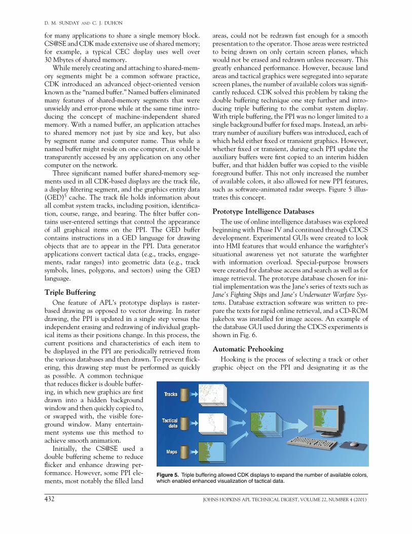
areas, couldnotbe redrawn fast enough for a smoothpresentationtotheoperator.Thoseareaswererestrictedto being drawn on only certain screen planes, whichwouldnotbeerasedandredrawnunlessnecessary.Thisgreatlyenhancedperformance.However,becauselandareasandtacticalgraphicsweresegregatedintoseparatescreenplanes,thenumberofavailablecolorswassignifi-cantlyreduced.CDKsolvedthisproblembytakingthedoublebufferingtechniqueonestepfurtherandintro-ducing triple buffering to the combat system display.Withtriplebuffering,thePPIwasnolongerlimitedtoasinglebackgroundbufferforfixedmaps.Instead,anarbi-trarynumberofauxiliarybufferswasintroduced,eachofwhichheldeitherfixedortransientgraphics.However,whetherfixedortransient,duringeachPPIupdatetheauxiliarybufferswerefirstcopiedtoaninterimhiddenbuffer,andthathiddenbufferwascopiedtothevisibleforegroundbuffer.Thisnotonlyincreasedthenumberofavailablecolors,italsoallowedfornewPPIfeatures,suchassoftware-animatedradarsweeps.Figure5illus-tratesthisconcept.
Prototype Intelligence DatabasesTheuseofonlineintelligencedatabaseswasexplored
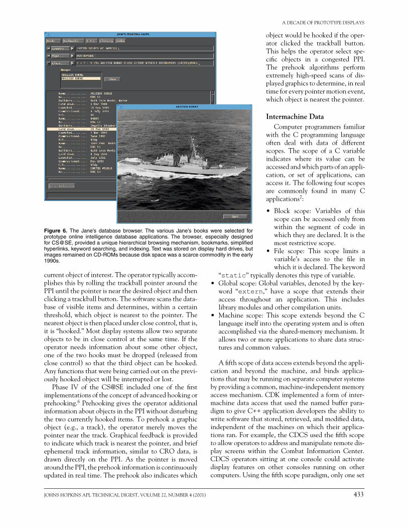
beginningwithPhaseIVandcontinuedthroughCDCSdevelopment.ExperimentalGUIswerecreatedtolookintoHMIfeaturesthatwouldenhancethewarfighter’ssituational awareness yet not saturate the warfighterwith information overload. Special-purpose browserswerecreatedfordatabaseaccessandsearchaswellasforimageretrieval.Theprototypedatabasechosenforini-tialimplementationwastheJane’sseriesoftextssuchasJane’s Fighting ShipsandJane’s Underwater Warfare Sys-tems.Databaseextractionsoftwarewaswrittentopre-parethetextsforrapidonlineretrieval,andaCD-ROMjukeboxwasinstalledforimageaccess.AnexampleofthedatabaseGUIusedduringtheCDCSexperimentsisshowninFig.6.
Automatic PrehookingHookingistheprocessofselectingatrackorother
graphic object on the PPI and designating it as the
Figure 5. Triple buffering allowed CDK displays to expand the number of available colors, which enabled enhanced visualization of tactical data.
as possible. A common techniquethatreducesflickerisdoublebuffer-ing,inwhichnewgraphicsarefirstdrawn into a hidden backgroundwindowandthenquicklycopiedto,or swapped with, the visible fore-ground window. Many entertain-ment systems use this method toachievesmoothanimation.
Initially, the CS@SE used adoublebufferingschemetoreduceflicker and enhance drawing per-formance.However,somePPIele-ments,mostnotablythefilledland
JOHNSHOPKINSAPLTECHNICALDIGEST,VOLUME22,NUMBER4(2001) 433
A DECADE OF PROTOTYPE DISPLAYS
currentobjectofinterest.Theoperatortypicallyaccom-plishesthisbyrollingthetrackballpointeraroundthePPIuntilthepointerisnearthedesiredobjectandthenclickingatrackballbutton.Thesoftwarescansthedata-baseofvisible itemsanddetermines,withinacertainthreshold,whichobjectisnearesttothepointer.Thenearestobjectisthenplacedunderclosecontrol,thatis,itis“hooked.”Mostdisplaysystemsallowtwoseparateobjectstobe inclosecontrolatthesametime.If theoperator needs information about some other object,oneof thetwohooksmustbedropped(released fromclosecontrol)sothatthethirdobjectcanbehooked.Anyfunctionsthatwerebeingcarriedoutontheprevi-ouslyhookedobjectwillbeinterruptedorlost.
Phase IV of the CS@SE included one of the firstimplementationsoftheconceptofadvancedhookingorprehooking.6PrehookinggivestheoperatoradditionalinformationaboutobjectsinthePPIwithoutdisturbingthetwocurrentlyhookeditems.Toprehookagraphicobject (e.g., a track), the operator merely moves thepointernearthetrack.Graphicalfeedbackisprovidedtoindicatewhichtrackisnearestthepointer,andbriefephemeral track information, similar to CRO data, isdrawn directly on the PPI. As the pointer is movedaroundthePPI,theprehookinformationiscontinuouslyupdatedinrealtime.Theprehookalsoindicateswhich
Figure 6. The Jane’s database browser. The various Jane’s books were selected for prototype online intelligence database applications. The browser, especially designed for CS@SE, provided a unique hierarchical browsing mechanism, bookmarks, simplified hyperlinks, keyword searching, and indexing. Text was stored on display hard drives, but images remained on CD-ROMs because disk space was a scarce commodity in the early 1990s.
objectwouldbehookediftheoper-ator clicked the trackball button.Thishelps theoperator select spe-cific objects in a congested PPI.The prehook algorithms performextremely high-speed scans of dis-playedgraphicstodetermine,inrealtimeforeverypointermotionevent,whichobjectisnearestthepointer.
Intermachine DataComputer programmers familiar
with the C programming languageoften deal with data of differentscopes. The scope of a C variableindicates where its value can beaccessedandwhichpartsofanappli-cation, or set of applications, canaccessit.Thefollowingfourscopesare commonly found in many Capplications7:
• Block scope: Variables of thisscopecanbeaccessedonlyfromwithin the segment of code inwhichtheyaredeclared.Itisthemostrestrictivescope.
• File scope: This scope limits avariable’s access to the file inwhichitisdeclared.Thekeyword
“static”typicallydenotesthistypeofvariable.• Globalscope:Globalvariables,denotedbythekey-
word “extern,” have a scope that extends theiraccess throughout an application. This includeslibrarymodulesandothercompilationunits.
• Machine scope: This scope extends beyond the Clanguageitselfintotheoperatingsystemandisoftenaccomplishedviatheshared-memorymechanism.Itallowstwoormoreapplicationstosharedatastruc-turesandcommonvalues.
Afifthscopeofdataaccessextendsbeyondtheappli-cation and beyond the machine, and binds applica-tionsthatmayberunningonseparatecomputersystemsbyprovidingacommon,machine-independentmemoryaccessmechanism.CDKimplementedaformofinter-machinedataaccess thatused thenamedbufferpara-digmtogiveC++applicationdeveloperstheabilitytowritesoftwarethatstored,retrieved,andmodifieddata,independentof themachinesonwhich their applica-tionsran.Forexample,theCDCSusedthefifthscopetoallowoperatorstoaddressandmanipulateremotedis-play screens within the Combat Information Center.CDCSoperators sitting at one console could activatedisplay features on other consoles running on othercomputers.Usingthefifthscopeparadigm,onlyoneset
434 JOHNSHOPKINSAPLTECHNICALDIGEST,VOLUME22,NUMBER4(2001)
D. M. SUNDAY and C. J. DUHON
ofsoftwarecodewasrequiredtocontroldisplayfeaturesonboththelocalandremotecomputers.
Fault ToleranceItisthenatureofcombatsystemsthattheyshouldbe
availableallthetimeandsuffernofaults.Itisalsothenatureof software systems that,becauseof theircom-plexity,itisusuallynotpossibletotestallcomponentsunderallpossibleinputcombinations.Theformercon-ditionstrivesfornofaults,whilethelatteradmitsthatfaultswilloccur.OnegoalofAPL’sprototypesystemswastocreatearobustenvironmentthatcouldallowforfaults,identifythem,andrecover.
Anarchitecturefordealingwithsoftwarefaultsthatoccurred in the form of an abnormal termination ofoneormoreapplicationswasdevised.Itconsistedofadaemonprogramcalledthesivadaemon(sivad)process,which itself initiated all other display programs. As aparentofthoseprograms,sivad,viatheUNIX“fork”mechanisms,couldmonitoranddetectabnormaltermi-nations.Whensuchanabnormalitywasdetected,theparent sivad process would immediately reinitiate thefaulty application.Thismechanismhasallowedmanyof APL’s prototype systems to remain operational forweeksatatimewhileparticipatinginat-seatrials.
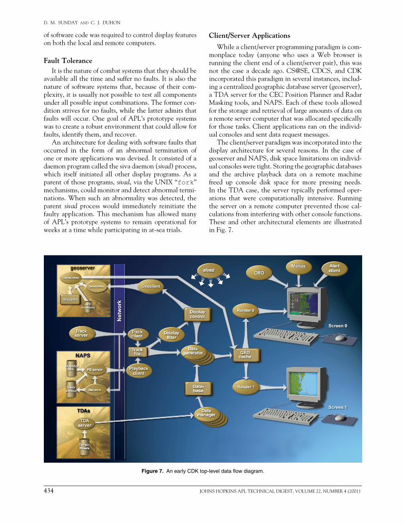
Figure 7. An early CDK top-level data flow diagram.
Client/Server Applications
Whileaclient/serverprogrammingparadigmiscom-monplace today (anyone who uses a Web browser isrunningtheclientendofaclient/serverpair),thiswasnot thecaseadecadeago.CS@SE,CDCS,andCDKincorporatedthisparadigminseveralinstances,includ-ingacentralizedgeographicdatabaseserver(geoserver),aTDAserverfortheCECPositionPlannerandRadarMaskingtools,andNAPS.Eachofthesetoolsallowedforthestorageandretrievaloflargeamountsofdataonaremoteservercomputerthatwasallocatedspecificallyforthosetasks.Clientapplicationsranontheindivid-ualconsolesandsentdatarequestmessages.
Theclient/serverparadigmwasincorporatedintothedisplay architecture for several reasons. In the caseofgeoserverandNAPS,diskspacelimitationsonindivid-ualconsolesweretight.Storingthegeographicdatabasesand the archive playback data on a remote machinefreed up console disk space for more pressing needs.IntheTDAcase,theservertypicallyperformedoper-ations that were computationally intensive. Runningtheserveronaremotecomputerpreventedthosecal-culationsfrominterferingwithotherconsolefunctions.These andother architectural elements are illustratedinFig.7.
JOHNSHOPKINSAPLTECHNICALDIGEST,VOLUME22,NUMBER4(2001) 435
A DECADE OF PROTOTYPE DISPLAYS
THE AUTHORS
DANIELM.SUNDAYisaPrincipalProfessionalStaffmathematician inAPL’sAirDefenseSystemsDepartment.HeobtainedaB.Sc.inmathematicsandphysicsfrom the University of Toronto in 1967 and a Ph.D. in mathematics from theUniversityofMinnesotain1971.From1975to1978hewasanNRSAPostdoc-toralFellowinbioengineeringattheUniversityofCalifornia,Berkeley.Dr.SundayjoinedAPLin1980andhasworkedonprojectsthatincludetheTRIMISmedicalsystem, theHIOSnetwork for theArmy,CS@SE,andCEC.Since1995hehasbeenthe leadsoftwareengineer for theE-2C“Hawkeye2000”ACISproductiondisplaysnowbeingdeployedinNavysquadrons.Dr.Sundayhasnotablepublica-tionsincomputerscience;hisareasofinterestincludecomputeralgorithms,com-puter graphics, computational geometry, and software development engineering.HeteachescoursesincomputergraphicsandcomputationalgeometryattheJHUWhitingSchoolofEngineering.Hise-mailaddressisdaniel.sunday@jhuapl.edu.
CHRISTOPHERJ.DUHONisamemberofAPL’sSeniorProfessionalStaffandSupervisor of the Advanced Display Technology and Development Section inADSD’sComputerSystemsDevelopmentGroup.HereceivedaB.S.degreeincom-puterscienceandinmathematicsfromtheUniversityofSouthwesternLouisianain1984andanM.S.degreeincomputersciencefromTexasA&MUniversityin1990.Mr.Duhon joinedAPL in1991andhasbeen involved in thedesignanddevel-opmentofadvancedcommandandcontrolsoftwaresystemsforthesurfaceNavy,includingtheCS@SE,CDK,andCEC.HeiscurrentlyleadengineerfortheCECdisplaysystem,workingonprototypeuserinterfacesandgraphicalvisualization.Hise-mailaddressischris.duhon@jhuapl.edu.
CONCLUSIONInthelate1990s,theNavyofficiallytransitionedthe
CDKprojectfromAPLtoindustry.Afterthat,theCDKteam dispersed and no more new code was developed.However, the Laboratory collected bug fixes from thenumerous CDK users, and a final stable release (CDK4.4)4wasdeliveredinDecember2000.ACD-ROMwiththissoftwareisavailablefromAPLthroughtheauthors.
REFERENCES 1Willey,F.J.,andNesbitt,D.W.,“AdvancedGraphicsforCommand
Displays,”Nav. Eng. J.98,130–137(May1986). 2Buscher,D.J.,andSunday,D.M.,“TheCommandSupportAt-Sea
Experiment,”Nav. Eng. J.102(3),25–36(May1990). 3Grant,C.J.,“AegisAAWCorrelator/Tracker(AACT)Experiment,”
Nav. Eng. J.102(3),37–42(May1990).
4Davis, D. E., Nesbitt, D. W., and Mallder, V. A., Common Display Kernel (CDK) V4.4 Application Programmer Interface (API), ADS-98-078,JHU/APL,Laurel,MD(Aug2000).
5Nesbitt,D.W.,Graphics Entity Data Format Specification,F3D-3-1695,JHU/APL,Laurel,MD(17Mar1995).
6Osga, G., Combat Information Center Human–Computer Interface Design Studies, Naval Command, Control, and Ocean SurveillanceCenter,SanDiego,CA(Jun1995).
7Stroustrup, B., The C++ Programming Language, AT&T Bell Tele-phoneLaboratories(1991).
ACKNOWLEDGMENTS: TheworkdescribedinthisarticlewassponsoredbytheNavy’sAegis(PMS-400),CEC(PMS-465),andSSDS(PMS-461)projects.AtAPL,numerousmanagers,softwaredevelopers,andhardwarespecialistssup-portedthiseffort.InadditiontothesoftwareleadsmentionedintheBackgroundsection, key management support came from Jerry Bath, Warren Citrin, GaryGafke,JerryKrill,BobLundy,JimPalmer,DennisSerpico,WinkWilkinson,andBillZinger.Also,numeroussoftwaredeveloperssupportedtheseprojects,somanythattheycannotbelistedhere.Theeffortsofallthesepeopleultimatelymadetheseprojectsasuccess.