a critical analysis of the kap shui mun bridgepeople.bath.ac.uk/jjo20/conference2/2008/yung paper...
TRANSCRIPT

Proceedings of Bridge Engineering 2 Conference 2008 23 April 2008, University of Bath, Bath, UK
A CRITICAL ANALYSIS OF THE KAP SHUI MUN BRIDGE
Benedict Kai Kwan Yung1
1Department of Architecture & Civil Engineering, University of Bath
Abstract: This article provides a critical analysis of the Kap Shui Mun Bridge which was completed in 1997. On completion, the bridge was the world’s longest cable-stayed bridge carrying both road and railway traffic (Now it is the 2nd longest after the Oresund Bridge across Sweden and Denmark was built). This paper examines about the structures and aesthetics of the bridge, as well as providing some calculations in order to prove its stability and serviceability. Further, the Wind and Structural Health Monitoring System (WASHMS) would be briefly introduced to see how the system maintains the safety of the bridge.
Keywords: cable-stayed, incremental launching, railway, WASHMS
1 General Introduction
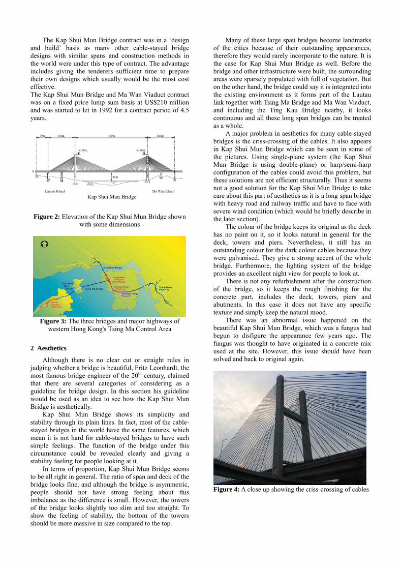
The Kap Shui Mun Bridge in Hong Kong was once the longest cable-stayed bridge in the world that transports both road and railway traffic (now it is the 2nd longest after the Oresund Bridge between Sweden and Denmark was built), with the upper deck for motor vehicles, and the lower deck for both vehicles and the Mass Transit Railway (MTR). The overall length of the bridge is 750 metres and with the main span of 430 metres. The bridge crosses over the main marine channel, Kap Shui Mun, and links between Ma Wan and Lantau Island which forms the Lautau link together with the Tsing Ma Bridge and Ma Wan Viaduct.
The bridge is basically not symmetric. The back spans of the bridge behind the towers are 160 metres, while the main span is 430 metres which means 215 metres cut my half. Therefore the length of the bridge in each section would be 160-215-215-160. The 503m Ma Wan Viaduct was connected to one end of the Kap Shui Mun Bridge and it was constructed under the same contract as the Kap Shui Mun Bridge. It connects the Kap Shui Mun Bridge to Tsing Ma Bridge (longest suspension bridge for road and railway traffic), and all these bridges form the Lantau Link that was built to provide access to the new airport. The navigation clearance of the Kap Shui Mun Bridge is 47m to allow large ships passing across, and this is the reason why the H-shaped towers are 150 metre tall.
In order to provide balance which usually would be stabilised by symmetry, the bridge has composite cross
sections which are relatively more complex compared with other similar cable-stayed bridges. At the central 387 metre of the main span, the deck uses steel composite with concrete with the aim of making the cross section lighter. In fact, this is also easier for the uplifting during construction. The back spans of the two sides and the remaining main span (which is 430 - 387 = 43 metres) are concrete cross sections. Using the lighter steel cross section in most of the main span could balance the horizontal forces on the towers and also the bridge.
Vierrendeel truss is designed for the lower deck because it has to allow rail and traffic to cross the bridge Hence no diagonal members would be underneath the deck parallel to the bridge and so more considerations have to be included in the design.
Figure 1: A top view of Kap Shui Mun Bridge
The Kap Shui Mun Bridge contract was in a ‘design and build’ basis as many other cable-stayed bridge designs with similar spans and construction methods in the world were under this type of contract. The advantage includes giving the tenderers sufficient time to prepare their own designs which usually would be the most cost effective. The Kap Shui Mun Bridge and Ma Wan Viaduct contract was on a fixed price lump sum basis at US$210 million and was started to let in 1992 for a contract period of 4.5 years.
Figure 2: Elevation of the Kap Shui Mun Bridge shown
with some dimensions
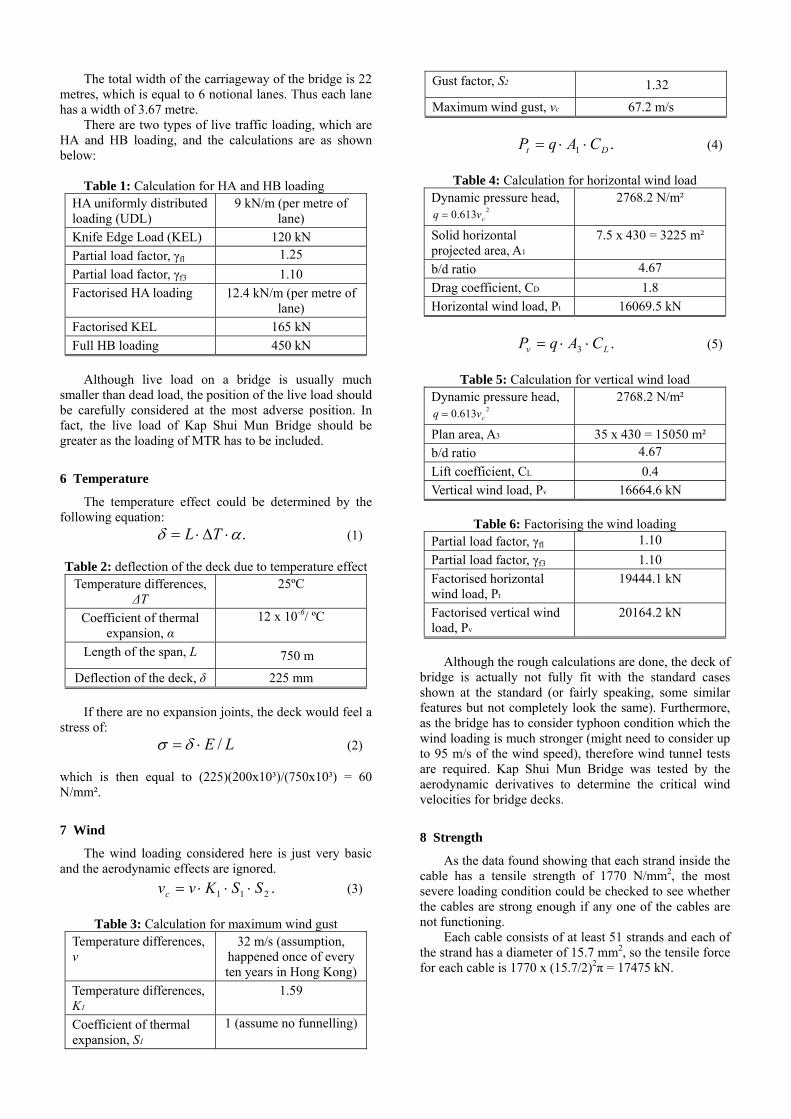
Figure 3: The three bridges and major highways of
western Hong Kong's Tsing Ma Control Area
2 Aesthetics
Although there is no clear cut or straight rules in judging whether a bridge is beautiful, Fritz Leonhardt, the most famous bridge engineer of the 20th century, claimed that there are several categories of considering as a guideline for bridge design. In this section his guideline would be used as an idea to see how the Kap Shui Mun Bridge is aesthetically.
Kap Shui Mun Bridge shows its simplicity and stability through its plain lines. In fact, most of the cable-stayed bridges in the world have the same features, which mean it is not hard for cable-stayed bridges to have such simple feelings. The function of the bridge under this circumstance could be revealed clearly and giving a stability feeling for people looking at it.
In terms of proportion, Kap Shui Mun Bridge seems to be all right in general. The ratio of span and deck of the bridge looks fine, and although the bridge is asymmetric, people should not have strong feeling about this imbalance as the difference is small. However, the towers of the bridge looks slightly too slim and too straight. To show the feeling of stability, the bottom of the towers should be more massive in size compared to the top.
Many of these large span bridges become landmarks of the cities because of their outstanding appearances, therefore they would rarely incorporate to the nature. It is the case for Kap Shui Mun Bridge as well. Before the bridge and other infrastructure were built, the surrounding areas were sparsely populated with full of vegetation. But on the other hand, the bridge could say it is integrated into the existing environment as it forms part of the Lautau link together with Tsing Ma Bridge and Ma Wan Viaduct, and including the Ting Kau Bridge nearby, it looks continuous and all these long span bridges can be treated as a whole.
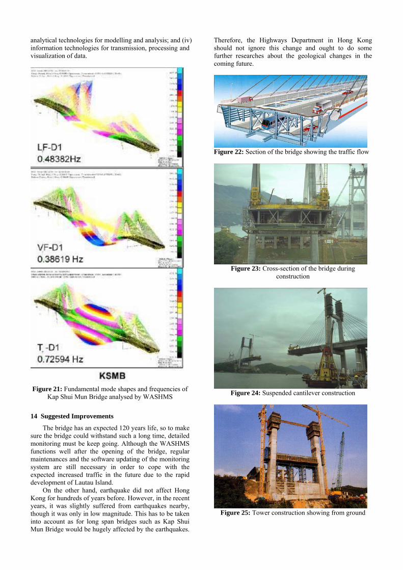
A major problem in aesthetics for many cable-stayed bridges is the criss-crossing of the cables. It also appears in Kap Shui Mun Bridge which can be seen in some of the pictures. Using single-plane system (the Kap Shui Mun Bridge is using double-plane) or harp/semi-harp configuration of the cables could avoid this problem, but these solutions are not efficient structurally. Thus it seems not a good solution for the Kap Shui Mun Bridge to take care about this part of aesthetics as it is a long span bridge with heavy road and railway traffic and have to face with severe wind condition (which would be briefly describe in the later section).
The colour of the bridge keeps its original as the deck has no paint on it, so it looks natural in general for the deck, towers and piers. Nevertheless, it still has an outstanding colour for the dark colour cables because they were galvanised. They give a strong accent of the whole bridge. Furthermore, the lighting system of the bridge provides an excellent night view for people to look at.
There is not any refurbishment after the construction of the bridge, so it keeps the rough finishing for the concrete part, includes the deck, towers, piers and abutments. In this case it does not have any specific texture and simply keep the natural mood.
There was an abnormal issue happened on the beautiful Kap Shui Mun Bridge, which was a fungus had begun to disfigure the appearance few years ago. The fungus was thought to have originated in a concrete mix used at the site. However, this issue should have been solved and back to original again.
Figure 4: A close up showing the criss-crossing of cables

Figure 5: Night view of the Kap Shui Mun Bridge with
the decorative lighting
3 Construction
Because this bridge project was in ‘design and build’ basis, the contractor had their own choices in building the bridge. The contractor decided to construct the side spans by incremental launching method (Figure 6, 7, 8).
There are many advantages of using incremental launching, such as no falsework is needed, only require one set of formwork, no transportation costs for precast concrete, high quality compared to concrete that cast in-situ, cranes are not required, etc. Nevertheless, the downsides of using this method have to be in consideration as well. It requires large areas behind the abutments to form as a concrete factory in order to harden the concrete deck and push it out. Fortunately, it was not the case that the Kap Shui Mun Bridge project had to worry about because the surrounding was rather remote area before the start of construction. Because the bridge needed to build was straight and with constant cross section, incremental launching was a good choice for construction.
The spans were divided into approximately 18 metre long units. After the first unit was cast, a steel launching nose was connected to the first unit and then moved towards the towers by 18m; the next unit was then cast behind the in-situ factory and joined to the first unit. After the two units joined together with the launching nose moved forward again a third unit was cast and connected to the second unit. This process was repeated until the first unit had just passed through the tower leg, which was the length of the complete side span. The launching nose became the first main span unit afterwards. This made the later stage of construction easy over the rugged terrain adjacent to the channel.
The abutments supporting the spans in fact are not evenly distributed; it might be due to aesthetic reasons. To achieve this temporary supports were needed within those longer spans (which was longer than 18 metre). Those temporary supports could not be removed until the whole construction finished.
The steel launching nose was always tapered near its end because when it was pushed to the next support the nose would deflect downwards due to the self-load, so the tapered nose enabled it to get back to the next support easier without any rising process required.
For incremental launching, it is very important that to keep the formwork straight, as it would affect the entire span significantly even if one piece of unit is slightly move apart.
For the main span of Kap Shui Mun Bridge, it used steel and concrete composite construction. Steel cross frames and steel plate exterior webs are used inside, while the top and bottom of the slabs forming the carriageways are in concrete. The steel cross Vierendeel frames are at 4.35m intervals.
The suspended cantilever construction method (shown at Figure 23) was used at the main span, which means using cable stays to help support the cantilever (which was the segment being lifted up and placed). This method could reduce the enormous hogging moment acting over the pier during cantilever construction, and because the bridge is a cable-stayed bridge originally, these cables became permanent stayed cables and did not need to alter them.
Figure 6: Incremental launching of the deck of Kap Shui
Mun Bridge (real photo)
Figure 7: Picture showing temporary supports and
permanent abutments of the bridge

The steel and concrete composite main span was erected by cantilevering at the same time with incremental launching of side spans from both towers. The steel units were prefabricated in Sheko in mainland, then each of the 8.7m long 500 tonne segment (approximately 44 segments) was assembled at the Lantau site before being lifted into position from barges in the channel.
Figure 8: Incremental launching of Ma Wan side span
Figure 9: Erection of main span
All the cables consist of 51 to 102 parallel mono
strands. Each of the strands is 15.7mm diameter sheathed 7 wire strands. The tensile strength after galvanising is 1770 N/mm². The entire weight of cables is 2400 tonnes with a total length of 11km. To protect the cables from corrosion, zinc galvanising, grease and 1mm extruded PE sheathing are used. Moreover, each cable is enclosed in an HDPE pipe. Each of the 500 tonne deck unit was floated out on a barge and then lifted into position by a pair of lifting gantries which mounted on the deck that was
previously secured. The lifting gantries would hold the unit until the essential connection had been made and stay cables were installed. The bridge also had a section of approach span on both ends of the side span.
High-strength friction grip bolts were used for all field joints of the steel structure.
Figure 10: Erecting main span deck unit of Kap Shui
Mun Bridge (Ma Wan side)
Figure 11: Extensive temporary works on Kap Shui Mun
Bridge

Figure 12: The bridge tower of the Kap Shui Mun Bridge
during construction.
Figure 13: Railway under the deck during construction
4 Foundation & Geotechnics
The two towers of Kap Shui Mun Bridge are founded by different methods. One of them (Lantau tower) is founded on a shallow spread footing on rock, while another one (Ma Wan tower) is founded partly on 4m diameter hand-dug piles and partly resting on rock. For such a long span and using different foundation technique, differential settlement must occurred and therefore monitoring of the settlement before construction was vital.The wind loading considered here is just very basic and the aerodynamic effects are ignored.
For the abutments, there is not sufficient information about their foundations, but by prediction from the towers the abutments on Ma Wan side should be in deep foundations using large diameter piles because the soil on that side should have more differential settlement. On the
other hand, for the same reason, the abutments on Lantau tower side should be sitting on shallow footing because of the existence of rock.
Figure 14: Cross-section of main span
Figure 15: Cross-section of side span
5 Loading
The following are the most important loadings to be considered:
1. Dead load; 2. Superimposed dead load; 3. Live traffic load; 4. Wind load (discussed in later section); 5. Temperature effect (discussed in later section). According to these loadings, both the ultimate limit
state (ULS) and serviceability limit state (SLS) have to be checked to ensure the bridge could be utilised and do not collapse.
5.1 Dead Load
Since the thicknesses of each support wall within the girders are different, it is relatively hard to estimate the dead load. Therefore, here using the data found from other sources and the dead load is 500 tonnes for 8.7 metres, which is equal to 575 kN/m. By multiplying γfl = 1.15 the factorised dead load is 661.3 kN/m.
5.2 Superimposed Dead Load
Even though there is lack of information about the superimposed dead load of Kap Shui Mun Bridge, making an assumption of 25 kN/m superimposed dead load for a typical cable-stayed bridge should be fair enough. By multiplying γfl = 1.75 the factorised superimposed dead load is 43.8 kN/m.
5.3 Live Load
In order to calculate the traffic loading on the bridge, notional lanes have to be defined first.
The total width of the carriageway of the bridge is 22 metres, which is equal to 6 notional lanes. Thus each lane has a width of 3.67 metre.
There are two types of live traffic loading, which are HA and HB loading, and the calculations are as shown below:
Table 1: Calculation for HA and HB loading
HA uniformly distributed loading (UDL)
9 kN/m (per metre of lane)
Knife Edge Load (KEL) 120 kN Partial load factor, γfl 1.25 Partial load factor, γf3 1.10 Factorised HA loading 12.4 kN/m (per metre of
lane) Factorised KEL 165 kN Full HB loading 450 kN
Although live load on a bridge is usually much
smaller than dead load, the position of the live load should be carefully considered at the most adverse position. In fact, the live load of Kap Shui Mun Bridge should be greater as the loading of MTR has to be included.
6 Temperature
The temperature effect could be determined by the following equation:
.αδ ⋅Δ⋅= TL (1)
Table 2: deflection of the deck due to temperature effect Temperature differences,
ΔT 25ºC
Coefficient of thermal expansion, α
12 x 10-6/ ºC
Length of the span, L 750 m
Deflection of the deck, δ 225 mm If there are no expansion joints, the deck would feel a
stress of: LE /⋅= δσ (2)
which is then equal to (225)(200x10³)/(750x10³) = 60 N/mm².
7 Wind
The wind loading considered here is just very basic and the aerodynamic effects are ignored.
.211 SSKvvc ⋅⋅⋅= (3)
Table 3: Calculation for maximum wind gust Temperature differences, v
32 m/s (assumption, happened once of every ten years in Hong Kong)
Temperature differences, K1
1.59
Coefficient of thermal expansion, S1
1 (assume no funnelling)
Gust factor, S2 1.32
Maximum wind gust, vc 67.2 m/s
.1 Dt CAqP ⋅⋅= (4)
Table 4: Calculation for horizontal wind load Dynamic pressure head,
2613.0 cvq =2768.2 N/m²
Solid horizontal projected area, A1
7.5 x 430 = 3225 m²
b/d ratio 4.67 Drag coefficient, CD 1.8 Horizontal wind load, Pt 16069.5 kN
.3 Lv CAqP ⋅⋅= (5)
Table 5: Calculation for vertical wind load
Dynamic pressure head, 2613.0 cvq =
2768.2 N/m²
Plan area, A3 35 x 430 = 15050 m² b/d ratio 4.67 Lift coefficient, CL 0.4 Vertical wind load, Pv 16664.6 kN
Table 6: Factorising the wind loading
Partial load factor, γfl 1.10 Partial load factor, γf3 1.10 Factorised horizontal wind load, Pt
19444.1 kN
Factorised vertical wind load, Pv
20164.2 kN
Although the rough calculations are done, the deck of
bridge is actually not fully fit with the standard cases shown at the standard (or fairly speaking, some similar features but not completely look the same). Furthermore, as the bridge has to consider typhoon condition which the wind loading is much stronger (might need to consider up to 95 m/s of the wind speed), therefore wind tunnel tests are required. Kap Shui Mun Bridge was tested by the aerodynamic derivatives to determine the critical wind velocities for bridge decks.
8 Strength
As the data found showing that each strand inside the cable has a tensile strength of 1770 N/mm2, the most severe loading condition could be checked to see whether the cables are strong enough if any one of the cables are not functioning.
Each cable consists of at least 51 strands and each of the strand has a diameter of 15.7 mm2, so the tensile force for each cable is 1770 x (15.7/2)2π = 17475 kN.

Figure 16: A sketch showing the geometry of the tower
and the outermost cable
The most acute angle for the cable is tan-1(83/215) = 21.1º. The vertical force could be taken by that cable is 17475(sin21.1º) = 6291 kN.
The loadings considered are as follows:
Table 7: most severe loading for calculating tensile strength of cable
Factorised dead load 5750 kN Factorised KEL (6 lanes) 990 kN
HB loading (1.5 x full load per lane for 6 lanes)
4050 kN
Factorised HA UDL 647 kN The sum of all loading is 11437 kN, and because it is
a two-plane system bridge, the cable would take half of the loading which is 5719 kN. By comparing the numbers it is clear that the cables are strong enough to carry the most severe loading.
To consider about bending moment of the deck, the
simplest was to consider a two-support case:
Figure 17: Loading for maximum sagging moment (two-support case)
By using the numbers calculated above, the maximum sagging moment at centre could be evaluated.
Table 8: Calculation of maximum sagging moment Factorised dead load 661.3 kN/m
Factorised superimposed dead load
43.8 kN/m
Factorised KEL 990 kN Factorised live load (assume uniformly
distributed)
64.1 kN/m
Maximum sagging moment at centre
9430 kNm
Similarly, the maximum hogging moment at simplest
state could be found as below:
Figure 18: Loading for maximum sagging moment (two-support case)
Table 9: Calculation of maximum hogging moment Factorised dead load 661.3 kN/m
Factorised superimposed dead load
43.8 kN/m
Factorised live load (assume uniformly
distributed)
64.1 kN/m
Maximum hogging moment at centre
3346 kNm
However, to consider the sagging and hogging
moment for the whole span of the deck, calculation should be manipulated like the below cases:
Figure 19: Loading for maximum sagging moment (multi-support case)
Figure 20: Loading for maximum hogging moment (multi-support case)
where these can be simply done by computer analysis.
In reality, the accuracy of these moment analysis would be affected by whether the cables (the supports) have been adequately prestressed or not. If the cables do not prestress sufficiently, the bending moment would become greater especially towards the mid-span of the bridge.
Besides the two cases described above, other cases such as considering the combined load with temperature effects and wind load, with temporary loads (including erection loads) are also vital and must be checked beforehand.

9 Natural Frequency
To find the natural frequency of the bridge, a simplified approach could be used for calculation. However, this method is only a rough calculation and the result is an upper boundary, therefore it could only be used for initial design. Further analysis of frequency of the bridge must be taken.
4/)( mlEIlnn βω = (6) Table 10: Calculation for natural frequency
(βnl) ² 22.37 Young’s Modulus, E 150 GPa (assumption for
mixture of steel and concrete)
Length of the span, l 430 m
mass density per metre 57 tonne Second moment of area,
I 740 (m²)²
Natural frequency, ωn 5.33 Hz
Because the calculated natural frequency = 5.33 Hz > 5 Hz, it is said to be acceptable. However, this is a very rough calculation and some values above (e.g. Young’s modulus, second moment of area) are simply by guessing which might not be the actual case.
10 Creep
As concrete is the main body of the bridge, creep would be an issue to consider at the stage of designing and before the start of construction. However, even though for such a long span concrete composite bridge creep recovery would only last for about a year and usually recover during the construction period. Therefore, as the bridge has already being used for roughly ten years it should not be an issue to worry about.
11 Durability
The bridge is expected to last for 120 years in accordance to BS 5400. As the bridge belongs to the Highways Department in Hong Kong, the department has implemented a monitoring system in order to ensure the bridge functions well in all aspects. More detail explanation about the system would be discussed in section 13.
12 Serviceability
Because the bridge needs to allow the MTR crossing it, little deflections of the bridge would affect the railway; the design must have to be carefully considered and hence monitoring system is important (discussed in next section).
13 Wind and Structural Health Monitoring System (WASHMS)
Long-span bridges in the world now being aware of the health monitoring under proper operation as it would directly affect the bridges lifetime and also influence the transportation network system in the whole area.
Therefore, the Highways Department in Hong Kong has introduced a bridge health monitoring system called the WASHMS (wind and structural health monitoring system), which they use the system to monitor three main long-span bridges in Hong Kong including Kap Shui Mun Bridge, Tsing Ma Bridge and Ting Kau Bridge.
The major purpose of installing this health monitoring system is to check and identify if there are any problems in operation, and also to check every parts of the bridge are in good condition so that the bridge could be perfectly functioned under ultimate state loading and serviceability state loading. Therefore, durability and serviceability of this bridge would increase significantly because of this detailed monitoring system.
The system of WASHMS includes six integrating modules: the sensory system (SS); data acquisition and transmission system (DA&TS); data processing and control system (DP&SC); structural health evaluation system (SHES); portable data acquisition system (PDAS); and portable inspection and maintenance system (PIMS). Each of them is capable to stand-alone to operate even if abnormal conditions occurs which induce part of the system does not function properly. It is important because this would greatly reduce the risk of the whole system not working to monitor the bridge and therefore increase the reliability of the system.
The WASHMS has been divided into four levels of operation. The first level is the collection and delivery of signals from SS to DA&TS. The second level is to converse the collected signals into digital data and transmits the data to DP&S through fibre optic cabling network. The third level refers to the computer system which carries overall control of post-processing, archiving, display and data storage. The fourth level is about the high-performance computer system which takes bridge health evaluation works and generates the monitoring reports. Any part of the hardware failure would not affect the whole system as mentioned before, so even if one level stops working the hardware at other levels will continue their operation. The power failure in any individual unit would also not affect to the other parts of the function. The buffer memory of each data acquisition unit in DA&TS is able to collect data continuously at least last for 12 hours. On power restoration, the WASHMS is able to arrange staging up of each lower level unit, and obtain status reports from each data acquisition unit such that no data overloading will occur.
The monitoring items are divided into three categories, (i) the loading sources (or input parameters) which include wind, temperature, traffic (highway and railway) and seismic loadings; (ii) system characteristics (or system parameters) which include static influence coefficients and global dynamic characteristics; and (iii) bridge responses (or output parameters) which include variation in geometric configuration (or displacements of the bridges), stress/strain distribution, cable forces and fatigue stress estimation.
The design and operation of a bridge health monitoring system requires the input of experiences and technologies in four aspects: (i) design, construction, operation and maintenance of long-span bridges; (ii) instrumentation technologies for collection and processing of data; (iii) graphical CAD and numerical
analytical technologies for modelling and analysis; and (iv) information technologies for transmission, processing and visualization of data.
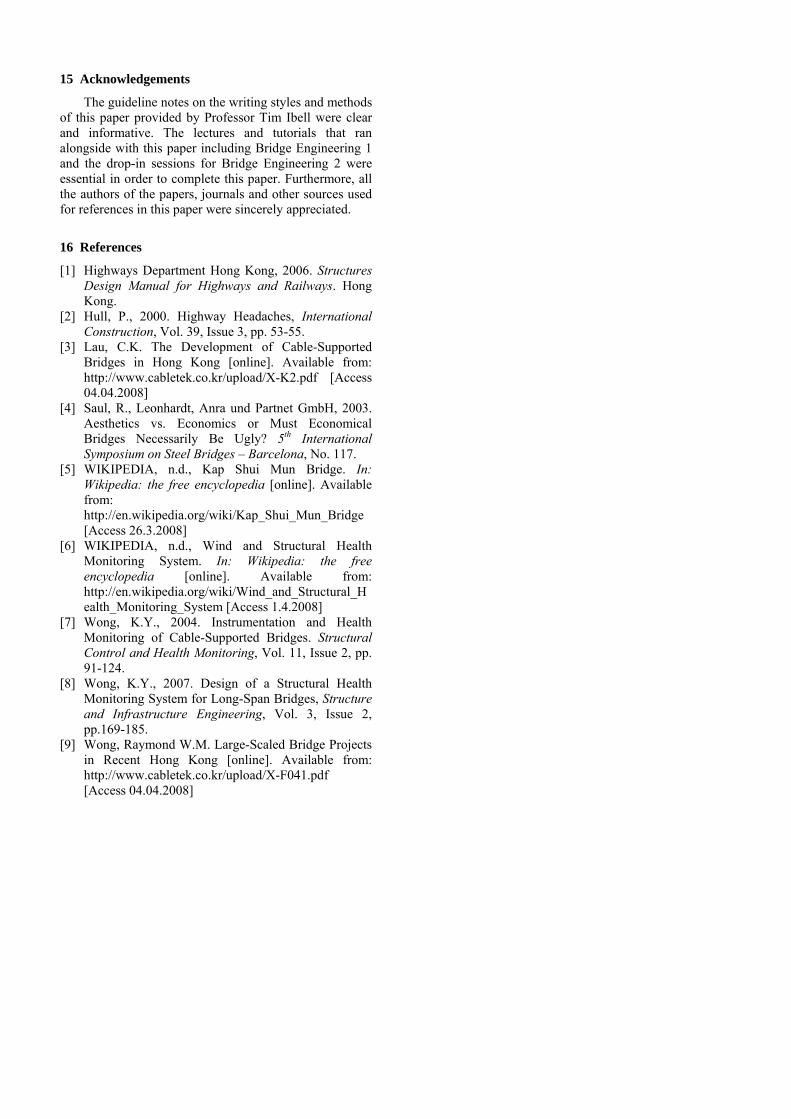
Figure 21: Fundamental mode shapes and frequencies of
Kap Shui Mun Bridge analysed by WASHMS
14 Suggested Improvements
The bridge has an expected 120 years life, so to make sure the bridge could withstand such a long time, detailed monitoring must be keep going. Although the WASHMS functions well after the opening of the bridge, regular maintenances and the software updating of the monitoring system are still necessary in order to cope with the expected increased traffic in the future due to the rapid development of Lautau Island.
On the other hand, earthquake did not affect Hong Kong for hundreds of years before. However, in the recent years, it was slightly suffered from earthquakes nearby, though it was only in low magnitude. This has to be taken into account as for long span bridges such as Kap Shui Mun Bridge would be hugely affected by the earthquakes.
Therefore, the Highways Department in Hong Kong should not ignore this change and ought to do some further researches about the geological changes in the coming future.
Figure 22: Section of the bridge showing the traffic flow
Figure 23: Cross-section of the bridge during
construction
Figure 24: Suspended cantilever construction
Figure 25: Tower construction showing from ground
15 Acknowledgements
The guideline notes on the writing styles and methods of this paper provided by Professor Tim Ibell were clear and informative. The lectures and tutorials that ran alongside with this paper including Bridge Engineering 1 and the drop-in sessions for Bridge Engineering 2 were essential in order to complete this paper. Furthermore, all the authors of the papers, journals and other sources used for references in this paper were sincerely appreciated.
16 References
[1] Highways Department Hong Kong, 2006. Structures Design Manual for Highways and Railways. Hong Kong.
[2] Hull, P., 2000. Highway Headaches, International Construction, Vol. 39, Issue 3, pp. 53-55.
[3] Lau, C.K. The Development of Cable-Supported Bridges in Hong Kong [online]. Available from: http://www.cabletek.co.kr/upload/X-K2.pdf [Access 04.04.2008]
[4] Saul, R., Leonhardt, Anra und Partnet GmbH, 2003. Aesthetics vs. Economics or Must Economical Bridges Necessarily Be Ugly? 5th International Symposium on Steel Bridges – Barcelona, No. 117.
[5] WIKIPEDIA, n.d., Kap Shui Mun Bridge. In: Wikipedia: the free encyclopedia [online]. Available from: http://en.wikipedia.org/wiki/Kap_Shui_Mun_Bridge [Access 26.3.2008]
[6] WIKIPEDIA, n.d., Wind and Structural Health Monitoring System. In: Wikipedia: the free encyclopedia [online]. Available from: http://en.wikipedia.org/wiki/Wind_and_Structural_Health_Monitoring_System [Access 1.4.2008]
[7] Wong, K.Y., 2004. Instrumentation and Health Monitoring of Cable-Supported Bridges. Structural Control and Health Monitoring, Vol. 11, Issue 2, pp. 91-124.
[8] Wong, K.Y., 2007. Design of a Structural Health Monitoring System for Long-Span Bridges, Structure and Infrastructure Engineering, Vol. 3, Issue 2, pp.169-185.
[9] Wong, Raymond W.M. Large-Scaled Bridge Projects in Recent Hong Kong [online]. Available from: http://www.cabletek.co.kr/upload/X-F041.pdf [Access 04.04.2008]