a critical analysis of sao paulo’s octavio … · a critical analysis of sao paulo’s octavio...
TRANSCRIPT
A CRITICAL ANALYSIS OF SAO PAULO’S OCTAVIO FRIAS DE
OLIVEIRA ROAD BRIDGE
Edward C Wilkes1
1Undergraduate student University of Bath
Abstract: This is a detailed paper on the Octavio Frias De Oliveira bridge in Sao Paulo. It will initially cover
how the requirement for such a bridge came about and how the chosen design fulfilled these requirements. A
structural analysis will be carried out, including relevant design calculation checks to British Standards. The
paper will discuss the aesthetics, construction and other issues including future changes and improvements.
Keywords: cable-stayed, centrifugal, curved deck, Inclined towers, junction.
1 Introduction
The bridge Octavio Frias De Oliveira is a unique
reinforced concrete, cable-stayed highway bridge
consisting of two separate curved bridge decks with a
total span of 290m each. It is situated in the heart of
Sao Paulo, Brazil, and provides an important road
connection aimed at reducing congestion in the city.
1.1 Sao Paulo congestion
Since the beginning of the 20th Century, post world
war and depression in the US, Sao Paulo has
undergone an industrial boom. This has seen a
dramatic rise in the population and a subsequent rapid
expansion of the city. This has lead Sao Paulo to
become one of the most congested cities in the world,
having a fleet of over 6 million cars. As a result, the
city’s road network is undergoing significant
investment and reconstruction [1].
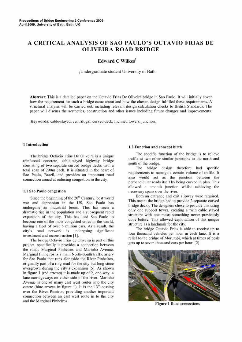
The bridge Octavio Frias de Oliveira is part of this
project, specifically it provides a connection between
the roads Marginal Pinheiros and Marinho Avenue.
Marginal Pinheiros is a main North-South traffic artery
for Sao Paulo that runs alongside the River Pinheiros,
originally part of a ring road for the city but long since
overgrown during the city’s expansion [5]. As shown
in figure 1 (red arrows) it is made up of 2, one-way, 4
lane carriageways on either side of the river. Marinho
Avenue is one of many east west routes into the city
centre (blue arrows in figure 1). It is the 13th cossing
over the River Pineiros, providing another important
connection between an east west route in to the city
and the Marginal Pinheiros.
1.2 Function and concept birth
The specific function of the bridge is to relieve
traffic at two other similar junctions to the north and
south of the bridge.
The bridge design therefore had specific
requirements to manage a certain volume of traffic. It
also would act as the junction between the
perpendicular roads itself by being curved in plan. This
allowed a smooth junction whilst achieving the
necessary spans over the river.
Both an entrance and exit slipway were required.
This meant the bridge had to provide 2 separate curved
bridge decks. The designers chose to provide this using
only one support tower, creating a twin cable stayed
structure with one mast; something never previously
done before. This allowed exploitation of this unique
structure as a landmark for the city.
The bridge Octavio Frias is able to receive up to
four thousand vehicles per hour in each lane. It is a
relief to the bridge of Morumbi, which at times of peak
gets up to seven thousand cars per hour. [2]
Figure 1 Road connections
Proceedings of Bridge Engineering 2 Conference 2009
April 2009, University of Bath, Bath, UK

2 Aesthetics
Bridge aesthetics will be analysed in accordance
with Fritz Leonhardts 10 rules for aesthetic analyses of
bridges. These 10 rules cover every aspect of bridge
aesthetics necessary for a successful design. Guidance
from Ref [8].
Figure 2 full bridge view and dramatic night shot
2.1 Fulfilment of function
This is an important area of bridge aesthetics for
producing a beautiful bridge. The main structural
element is the tower, this stands proud above the city at
a height of 138m. It can be seen to rise from ground
level to the top without interruption as a single
element, carrying the vertical loads from each of the
two bridge decks directly to the ground. This gives the
impression of strength and stability; the backbone to
the structural system. The cables at deck level are
clearly the main support for the deck, this is
accentuated by the shallow deck. However when your
eyes follow the cables up to the tower, it becomes
unclear as to which cables support what part of the
deck. This is due to the crossing over of the 144 cables.
This is a fundamental floor in the aesthetics of the
bridge; as soon as people are faced with the confusing
criss-cross of cables, the whole design looses its
beauty.
2.2 Proportions
The many cables however, have allowed the
bridge decks to be designed very shallow and sleek.
This is well proportioned against the strong primary
element, the tower. This draws your eyes to the tower
itself and its impressive shape, and away from the
messy net of cables. The cables begin to be viewed as a
single element that connects the stable tower to the
sleek deck; as such, the mess of cables becomes less of
an issue. The cross shape of the tower itself provides
areas of light and shadow underneath each side, which
help to accentuate its unique shape. However, to
prevent it appearing too bulky against the deck, a dark
line is apparent, splitting the tower in two, this makes it
appear as if there are two separate slimmer towers.
2.3 Order
Order is important in the lines and edges of a
bridge, repetition can be used to produce a crisp,
ordered design. The bridge deck is viewed as one
element, there are no horizontal lines or edges except
that of the mass of the deck itself. The bridge curves
with a satisfying constant curvature with equal spacing
of cable tie supports. The connections of the cables to
the deck are the only element that breaks up the soffit;
however these provide a reassuring functional effect
when viewed from beneath. The angle of each
connection is set into the concrete of the deck and
specifically angled to match the corresponding cable’s
angle. This ensures continuity of the line of action of
the cables when viewed from the side.
Although the shape of the bridge is so unique,
consisting of two curved decks, symmetry in the design
is still upheld. The two tracks are simple inverted
repetitions of each other even though they sit at
different levels.
2.4 Refinements
The tower is made up of two crossing, tapered
columns. The tapering is for structural efficiency,
however it also prevents the tower from looking top
heavy. The cable anchorages are expressed in the soffit
beneath the deck. These do not break the flow of the
slender deck however they act as a reminder to how the
deck is supported and highlights its reliance on the
primary element, the tower.
Figure 3 Refinements
2.5 Integration into environment
Cable stayed bridges work well in cityscapes.
Their towers can be tall and elegant, and the bridge
decks low and sleek. This bridge has achieved these,
however the bridge was meant to be a new, impressive
landmark for the city and through its unique design it
achieves this too. Its mast height is similar to that of
surrounding high rise office buildings so that it is not
too overwhelming in the area, although it gives so

much more to the city and to the landscape than any
convention structure or building.
2.6 Texture
Texture is an important feature on bridges. It is
often overlooked such as is the case with the bridge
Octavio. The finish on the bridge is a rough plain matt
finish. Each 3m stage of casting of the tower can
clearly be seen, and same goes with the deck. The soffit
from afar looks smooth, however upon closer
inspection, lines and defects in the surface from the
construction process are visible.
2.7 Colour
Colour is often used to create different effects on
bridges. The bridge Octavio Frias has a bright yellow
covering around the cables. This has been used with
previous cable-stayed bridges to contrast the blue sky.
It also gives the impression of diverging sun rays
breaking through clouds. The bright colour also helps
to blend the cables together and to reduce the negative
visual effect of them crossing.
Phillips have installed an advanced lighting system
consisting of LEDs into the bridge. The LED
ColorBlast projectors provided by Phillips allow the
dynamic interchange of colours. This allows the bridge
to be illuminated in almost any colour; possibly
reflecting special celebrations or events depending on
the time of year [3]. This further highlights how the
bridge can be looked upon as a local landmark as it can
be used to represent local and global occasions.
2.8 Character
The bridge Octavio Frias has huge amounts of
character. Its unique design is impressive; it causes
people to ask themselves how it works; how the
separate decks balance each other and how the loads
are shared through the tower, and whether in actual fact
it acts more like two separate bridges than one or if
each deck relies on the other for support.
2.9 Complexity
An amount of complexity within a bridge can be
visually interesting and exciting. The complexity due
to the crossing cables can provide this from certain
angles, however at others it can be chaotic as shown
below.
Figure 4 confusing array of cables
2.10 Nature
The incorporation of nature into structural design
of bridges and other structures can be a useful way to
make use, or remind people (through sculptural
appreciation) of the forms evolved over billions of
years by something other than man. There is some
mention of the influence of Leonardo da Vinci’s
Vitruvian Man on the design of the bridge highlighted
in Ref [4] as shown below. However there may be a
hint of architectural/sculptural post rationalization here.
Figure 5 Comparison to Vituvian man
3 Structural strategy
The bridge Octavio Frias de Oliveira is very
unique. It functions not only as a bridge to span the
river Pinheiros, but as the slip roads that form the
connection between the two perpendicular main roads.
Cable stayed bridges are best suited for medium-
span, low-level river crossings such as that required by
the bridge Octavio Frias de Oliveira. They largely only
transmit vertical loads through their foundations, which
is beneficial regarding the commonly poor ground
conditions adjacent to riverbanks. They are also elegant
and relatively cheap and simple compared to other
forms of bridge construction. For this particular
situation in Sao Paulo, a cable stayed bridge was
simply the only choice. Considering the requirement
for a bridge deck with such a tight curvature, most
bridge types are ruled out; such as suspension, stress
ribbon and cantilever. Many beam bridges in the same
area of Sao Paulo have been built with similar
curvatures, however with much smaller spans. An arch
bridge was not possible due to poor ground conditions.
Therefore a cable stayed bridge system had to be
created that could provide two separate curved traffic
carriageways from a single tower.
Two smaller, straight decked cable stayed bridges
were considered during the design process see Ref [4],
however this design was abandoned possibly because it
looked awkward, and because it did not provide a
smooth junction for traffic without requiring land space
adjacent to the river for the curved sliproads.
The solution was to form an X out of 2 towers,
each dedicated predominantly to each of the decks,
however gaining stability from a connection where
they cross. Each tower is inclined away from the
curved deck it is supporting. This ensures that forces in
the tower and the decks are mostly axial with minimal
bending. However due to eccentricities of the cable

resultant forces and the position of the deck (due to
curvature) out of plane bending is felt in the deck.
Sufficient longitudinal pre-stressed reinforcement is
provided throughout the deck to cope with these extra
tensile and compressive stresses as seen in figure 6
below. This reinforcement will also be responsible for
ensuring stiffness and stability of the deck under
centrifugal traffic loads on the curved carriageways.
Extra reinforcement is also provided in the tower to
cope with bending under uneven live loads.
Figure 6 longitudinal reinforcement (light green)
Cable stays (red and dark green) [4]
This inspired the deck section to be as in figure 7.
The two larger reinforced concrete sections at the
edges, span between the cable supports and also
produce a high second moment of area in the y-y plane
of the deck to cope with the lateral bending. The
thinner reinforced concrete slab predominantly spans
between the two edge beams to support the traffic
lanes, additionally it acts as a shear web for lateral
stiffness and in some parts compression due to
triangular arrangement of the cables.
Figure 7 Deck section through sagging region [4]
The cables support the deck in a semi fan
arrangement. They support each segment of the deck in
pairs. This pairing means that the support for the deck
is triangulated. This is a valuable advantage for cable
stayed bridges designed in this way; lateral stability of
the deck is dramatically increased, further allowing the
deck to be slimmer in depth.
The tower itself has built in triangulation in the
lower region due to the interconnected inclined towers.
This drastically improves lateral stability of the whole
bridge under uneven live loading such as centrifugal
traffic or extreme wind loads. This is important for
reducing moments on the foundations in the weak
strata beneath.
4 Calculations
The analysis of this bridge will be done in
accordance with BS 5400. Five load types are
considered; Dead, Superimposed dead, live traffic,
wind and temperature effects. These nominal loads will
be calculated, and the relevant partial factors applied.
They can then be applied in onerous and suitable
combinations to assess the bridge structurally by
comparing the effects against the element strengths.
4.1 Dead Loads
The volume of reinforced concrete in the deck has
been calculated as 10.5m3 per metre length, based on
deck sections from Ref [4]. Unit weight of reinforced
concrete = 24kN/m3. Therefore the dead load (DL) per
metre of deck = 10.5x24 = 252 kN/m. The dead load
can be factored using equation 1
DLfactored= DL γf1 γf3 (1)
Table 1 DL partial Factors for concrete for all load
combinations see Ref [7].
SLS ULS
γf1 1 1.15
γf3 1 1.1
ULS DLfactored = 252 x 1.15 x 1.1 = 318.7kN/m
SLS DLfactored = 252 x 1 x 1 = 252kN/m
4.2 Super-imposed dead loads (SIDL)
Super-imposed dead loading must be taken into
account when assessing the dead weight of the deck. It
is mainly made up from the steel barriers and asphalt
surface coating on the floor slab, plus some service
transmission lines, cables and lighting.
The weight of the barriers and services are
unknown, but can be assumed to add up to a UDL of
0.5kN/m2 covering the entire deck area. Density of
Stone Matrix Asphalt is 2300kg/m3, thickness of the
asphalt is 100mm, therefore weight/m2 = 23 x 0.1 =
2.3kN/m2, therefore total SIDL= 2.3 + 0.5 = 2.8kN/m
2
Deck width =10.5m, so UDL/m along deck = 10.5
x 2.3 = 24.15kN/m.
Table 3: partial factors for SIDL all combinations [7]
SLS ULS
γf1 1.2 1.75
γf3 1 1.1
ULS SI DLfactored = 24.15 x 1.75 x 1.1.= 46.5kN/m
SLS SI DLfactored = 24.15 x 1.2 x 1 = 31.9kN/m
4.3 Imposed Traffic loading
Each separate deck carries 2 marked lanes of
traffic plus a hard shoulder. This amounts to 10.5m of
carriageway width. In accordance with BS 5400 (Ref

[8]), this corresponds to 3 notional lanes, which is used
for derivation of the loads. Width of each notional lane
is therefore 10.5/3 = 3.5m.
HA loading is an imposed UDL acting over
notional lanes plus a knife edge load (KEL). Assuming
a loaded length of the entire span of the bridge (290m)
for assessing the HA loading, according to BS5400, the
Ha UDL per metre length of each notional lane can be
found from equation 2.
0.1
136W
L
= ×
(2)
L=loaded length=290m
Therefore HA UDL=20.8kN/m along one notional
lane. Dividing by the width of a notional lane gives the
UDL per metre squared: 20.8/3.5 = 5.94kN/m2
According to BS5400, a KEL of 120KN is
appropriate.
4.5 HB loading
HB loading, is based upon an abnormal truck load.
This load would rarely be exerted on the bridge,
however it may be the most severe load experienced by
the bridge in its life. The full 45 units will be applied,
this equates to 450kN per axle. When testing the deck,
the most severe effect may be caused by HB when the
axles are approximately at mid-span of two
consecutive deck spans between cable supports,
causing a maximum hogging moment over the central
support.
This requires a central axle spacing of 6m
corresponding to the deck span of 7.3m.
4.6 Wind loading
Specific calculation of wind pressure on structures
is a result of many different variables; wind tunnel
testing is certainly required for a true analysis of this
bridge due to the unique design. However it is beyond
the scope of this report. In accordance with BS5400,
the wind load can be derived based upon 120yr return
values. The maximum wind gust speed can be
calculated from equation 3.
Vc = v K1 S1 S1 (3)
v = mean hourly wind speed = 40m/s
K1 = wind coefficient from table
S1 = unnelling factor, can be taken as 1 for this
example
S2 = gust factor
vc = 40 x 1.43 x 1 x 1.07 = 61.2 m/s
Although tornadoes are not common in Sao Paulo,
they do happen, and must be taken into consideration
for extreme loading. This has been taken into account
by assuming a higher mean hourly wind speed. The
load exerted on the bridge must then be calculated
from equation 4.
Pt = q A1 Cd (4)
Where q = 0.613vc2 = 2296
A1 = solid horizontal projected area
Cd = drag coefficient as defined below
d = dl = 2.5m
For 1m length of deck, A1 = 2.5m
b/d ratio = 16/2.5 = 6.4
Therefore BS5400 states Cd = 1.25
Pt = 8609N/m = 8.61kN/m
Wind will also exert vertical loads on the bridge
deck. This also is important and must be calculated
from equation 5.
Pv = q A3 Cl (5)
A3 = plan area per metre deck = 16m2
Cl is defined below
For Cl, due to the curvature of the deck, it has a
certain super elevation built in to the design. This is
2.7% which is between 1 and 5 degrees. Therefore
BS5400 states Cl to be taken as 0.75.
Pv = 27550N/m = 27.6kN/m
Table 3 factors for wind for combination 2 [8]
SLS ULS
γf1 1 1.1
γf3 1 1.15 for a plastic analysis
SLS Pt factored = 8.61 x 1 x 1 = 8.61kN/m
SLS Pv factored = 27.6 x 1 x 1. = 27.6kN/m
ULS Pt factored = 8.61 x 1.1 x 1.15 = 10.9kN/m
ULS Pv factored = 27.6 x 1.1 x 1.15 = 34.9kN/m
4.7 Secondary live loads: Horizontal traffic loads
The bridge is unusual in that it has two curved
decks. Each of these decks can be treated separately for
their analysis. Horizontal centrifugal traffic loads will
occur as the traffic drive along the curved decks. For
an extreme case, BS5400 states that a horizontal load
of value given in equation 6 can be used, however this
is only a point load and is not suitable for analysing the
deck as a whole element under a UDL centrifugal load
from HA traffic.
30000
150cF
r=
+
(6)

r = the radius of the bend = 290m
Fc = 68.1kN
This is a single point load and is minimal
compared with the extreme horizontal wind loading.
4.9 Temperature effects
The bridge Octavio Frias has expansion joints at
the ends of the deck on side of the spans. Teflon
bearings are most likely provided over the support on
the tower. However these joints may become blocked
by debris at some point in the bridges life. This will
build up longitudinal stresses in the deck that may
contribute to failure of the section most likely by
buckling in compression where there is already high
compressive stresses, such as over the cable stay
supports. Assuming the coefficient of thermal
expansion (α) for reinforced concrete is 12µε/Co. Then
the stresses built up can be calculated directly from
equation 7. The bridge is in group 4 (concrete slab on
concrete beams)
Max. shade air temperature = 28 Ref [6]
Min. shade air temperature = -4 Ref [6]
Max. effective bridge temperature = 30 Ref [7]
Min. effective bridge temperature = -2 Ref [7]
( )T Eσ α= ∆ (7)
α= 12µε/Co
∆T=(30+2)Co
E=30GPa for concrete
σconcrete =12x10-6 x (30+2) x 30000 = 11.52N/mm
2
4.10 Braking and accelerating forces
Braking and accelerating forces can cause stresses
in the longitudinal direction of the bridge deck and
therefore must be considered in design. BS 5400 states
this can be taken as 8kN/m along a single notional lane
plus a 200kN force.
5 Load effects
5.1 Bending
To calculate the maximum bending moments
exerted in the deck, the deck is appropriately
considered as 2 continuous beams spanning between
the cable supports and a separate deck simply
supported between the beams. The beams are
considered to sit upon rigid cable supports; the cables
are assumed to have had the correct amount of
prestress put in them for the deck to act in this way.
This produces the first moment diagram in figure 10.
However the second moment diagram in figure 10
shows an exaggerated but more realistic approach
which takes into account the effect of the extension of
the cables on the moment diagram (i.e. the supports are
modelled as springs). Enough prestress will be put into
the cables to ensure this effect is kept to a minimum
when the deck is subject to imposed loadings plus any
future creep effects.
Figure 10 Deck moment diagrams
Maximum bending stresses are exerted in the deck
under load condition 2. The most onerous loading case
for vehicular imposed is taken as 2 notional lanes fully
laden with HA, and all other lanes with 1/3 HA, with
the KEL at central span. With maximum dead and
superimposed dead loads included. Wind load is
included.
Table 4 Partial factors for Live vehicle loading,
combination 2
SLS ULS
γf1 1 1.25
γf3 1 1.1
HAFactored ULS = 20.8 x 1.25 x 1.1 = 28.6kN/m
HAFactored SLS = 20.8 x 1 x 1 = 20.8kN/m
KELFactored ULS = 120 x 1.25 x 1.1 = 165kN
The span between each cable support is 7.3m,
assuming moments to develop as if each deck section
was fully fixed at both ends, the following free body
diagram can be drawn for the deck.
Maximum moments in the edge beams will occur in
hogging over the cable supports in the end span. This
moment can be found from equation 8.
Mhog =
2
8
wl (for UDL) +
3
16
Pl(KEL)
(8)
L=7.3m P=165kN w=29.6x2.33+46.5+318.7+3
4.9 =447kN/m
Mhog = 3203kNm. Assuming this is shared between
the two edge beams in the ratios 3:2 due to offset
loading, then Mhog =0.6x3203=1922kNm. The bending
stress exerted in the reinforced concrete section can be
calculated from equation 9.
My
Iσ =
(9)
M=1922kNm y=0.71m I=0.358m4
Calculated
σ = 3812kN/m2=3.81N/mm
2 (low stress)

5.2 Cable tension
The maximum force in any cable is experienced
under combination 2 loading in the end span where the
inclination of the cable is at its greatest. HB loading
will cause the most critical effects. HB loading will
cover 2 notional lanes with 1/3 HA on the final
notional lane. The vertical load (V) supported by a pair
of cables is the total loads over one span calculated
below. This is the sum of all DL, SIDL, HB, HA and
vertical wind loading. The HB vehicle is assumed to sit
with 2 axles at the point of support of the cables.
DL=318.7kN/m SIDL=46.5
kN/m
Wind=34.9kN/m
HA=0.333x29.6kN/m HB=450x2kN
V=3892kN.
The cables are at an angle of 37.8o to the
horizontal. Therefore the tension in the cable pair is
3892/sin37.8 = 6350kN. Assuming loads are carried in
the ratio 3:2 between the pair of cables due to the offset
HB load, then the tension in the most critical cable is
0.6x6350=3810kN.
The cables are assumed to be high yield steel.
They are pretensioned to relieve excessive sagging of
the deck under imposed loading. The required area of
steel for the cable can be calculated using equation 10
1.25
0.8 yield
PA
σ=
(10)
P=3.81x10⁶kN
yieldσ = 760N/mm2
x 1.25 for pretension x 0.8 for 80% of yield
A=7833mm2, This corresponds to a cable diameter
of 98mm. The actual cables on the bridge are 100mm
diameter.
5.3 Deck compression
Due to the inclination of the supporting cables,
they exert a compressive force in the deck. This force
will be at a maximum near to the tower. It will exert a
compressive stress into the section in this area that may
cause failure when combined with bending in the deck.
The maximum effect will be under load combination 2
with full HA loading, DL, SIDL, and wind. The
vertical load supported by the cable is
V=(2.333x29.6+318.7+46.5+34.9)x7.3=3425kN
Therefore the average cable pair tension is
3425/sin58=4039kN . The compression in the deck at
the tower is given by summing the horizontal
components of all 18 pairs of cables on one side of one
bridge deck. C=18x4039cos58=38526kN. The
compressive stress from this axial force can be
calculated from equation 11.
P
Aσ =
(11)
σ = 38526/10.5 = 3670kN/m2 = 3.67N/mm
2
5.4 Lateral bending
Lateral bending is experienced in the deck under
wind loading and centrifugal vehicle loading.
Furthermore, due to the curvature of the deck there is
an eccentricity associated with horizontal components
of the cable tensions which produces out of plane
moments in the deck as well as the axial compression.
These forces exert out of plane bending stresses in the
deck section, the moment can be calculated from
equation 12.
2
8 4
t ccables
Pl F lM eF n= + +
(12)
Pt=10.9kN/m Fc=68.1 e=eccentricity=2m
n=number of cables=36 Fcables
=1070kN
L=140
m
M=106000kNm. The stress in the concrete from
this moment can be calculated from equation 6 above.
M=106000kNm y=8m I=370m4
σ concrete= 2292kN/m2=2.3N/mm
2 (low stress)
6 Serviceability
All bridges and structures will undergo some
amount of deflection under loading. Ultimately, the
amount of local deflection is related to the external
imposed loads applied. However the amount of
prestress in the cables that support the deck has a
dramatic effect on the initial global deflections and
long term creep deflections. BS5400 specifies that only
load combination 1 should be taken into account for
serviceability. A maximum of 25 units of HB loading
are to be considered if this causes the most onerous
effects. Assuming the cable supports are inflexible, the
highest deflection will occur in the end span due to the
end simply supported connection. For a UDL, the
maximum initial deflection can be calculated for a
fixed pinned system using equation 13.
4
185
wL
EIδ =
(13)
w=357kN/m
SLS
L=7.3m E=4x10⁷
kN/m2
I=0.358m4
δ = 0.00038m = 0.38mm (insignificant)
7 Creep
Creep in concrete is a result of the continuing
setting of the concrete as it dries. It happens under the
effect of long term loads such as dead and super
imposed dead loads. The long term creep deflection
can be calculated for a loaded structural element of the
bridge. However, the small spans between the supports
of just 7.3m combined with the rigid beam elements
are unlikely to produce large long term defections.
Loss of prestress in the steel cables due to creep in the
steel is much more likely to produce significant long
term deflections over the length of the span. This can
have the effect of increasing the sagging moments in
the deck as shown in figure 10.
8 Natural Frequency
Vibrations in bridges can greatly influence their
design. It is important that the natural frequency of any
bridge does not fall within a certain range. This range
is between 5Hz and 75Hz. Above 75Hz can cause
physiological discomfort, below 5Hz and the bridge
could be excitable by cyclic wind or traffic loading,
and collapse could result. The natural frequency can be
below 5Hz, however some form of damping may be
necessary to limit the acceleration of the element. The
natural frequency of different elements of the bridge
can be calculated simply via the Rayleigh-Ritz
formula, equation 14.
( )2
2
0 4n n
EIF w l
mlβ = =
(14)
The values shown are natural frequencies for the
deck, both fixed-fixed and fixed-pinned configurations
are tested (assumed pinned at the end of the deck).
Values : E = 3x10^10N/m^2 I = 370m^4 m =
25200Kg/m l = 140m (span)
configuration (Bnl)^2
value
EI/ml^4 F0 value
Fixed fixed 22.37 1.147 23.96Hz
Fixed pinned 15.42 1.147 16.5Hz
5 < 23.96,16.5 < 75
As can be seen, both natural frequencies fall
within the permissible limits. However, this is only a
very simple preliminary analysis of the bridge using
basic formula. There may be many more complicated
vibration effects in this bridge such as coupling effects.
These can only be analysed using sophisticated
computer software, not within the scope of this paper.
9 Foundations and Geotechnics
Ground conditions and considerations often have a
dominant influence on the choice and design of bridges
and buildings alike. This is very much the case for the
bridge Octavio Frias. The location of the bridge is
adjacent to the Pinheiros river which is an affluent of
the Tiete River (which originally fuelled Sao Paulo’s
growth) which itself sits on a plateau in the Brazilian
highlands. The river Pinheiros has been extremely
polluted and as such has been canalised, now serving
little use to the city except small goods transportation.
However, adjacent strata to the river is still made up
largely from alluvial desposites built up during the
river Pinheiros’ life. It is on these deposites that the
bridge sits. These deposits are poor at carrying any
lateral loads or moments. It is common for suburban
mediam span river bridges to be cable stayed due the
nature of the way loads are carried and the common
poor soil conditions. Most cable stayed bridges such as
Octavio Frias de Oliveira work by keeping lateral loads
within the structure by balancing the deck either side of
the tower. Some fixity at the foundation of the tower is
still required for stability under uneven loading.
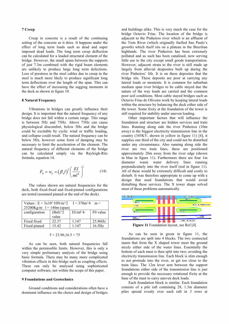
Other important factors that will influence the
foundation and structure are hidden services and train
lines. Running along side the river Pinheiros (10m
away) is the biggest electricity transmission line in the
country (345KV, shown in yellow in figure 11) [4], it
supplies one third of the city and could not be disturbed
under any circumstance. Also running along side the
river are two train lines, these are positioned
approximately 20m away from the river edge (shown
in blue in figure 11). Furthermore there are four 1m
diameter waste water delivery lines running
perpendicularly into the river itself (red in figure 11).
All of these would be extremely difficult and costly to
disturb. It was therefore appropriate to come up with a
design that used foundations that would avoid
disturbing these services. The X tower shape solved
most of these problems automatically.
Figure 11 Foundation layout, see Ref [4]
As can be seen in green in figure 11, the
foundations are spilt into 4 blocks. The two connected
masts that form the X shaped tower meet the ground
nicely either side of the water lines. Essentially the
bottom of each mast is then split into two; avoiding the
electricity transmission line. Each block is slim enough
to not protrude into the river, or get too close to the
train lines. The 12m lever arm between the support
foundations either side of the transmission line is just
enough to provide the necessary rotational fixity at the
base of the mast to carry uneven deck loads.
Each foundation block is similar. Each foundation
consists of a pile raft containing 28, 1.3m diameter
piles spread evenly over each raft in 3 rows at
approximately 2m spacing [4]. The depth of these piles
is unknown but is expected to be approximately 20-
30m. Furthermore there are 10, 0.4m diameter piles on
each block that are inclined outwards. These are
expected to be around 15m in length and provide extra
lateral stability adjacent to the river bank.
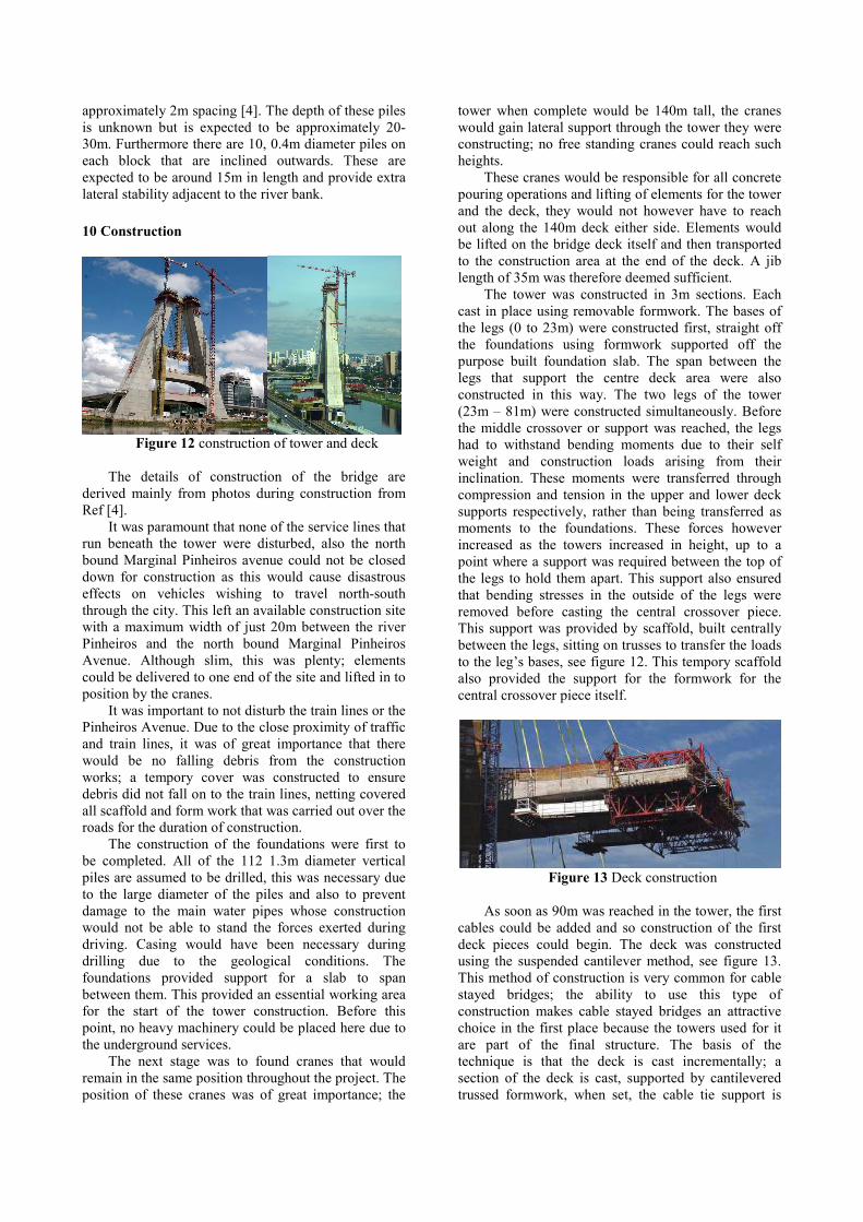
10 Construction
Figure 12 construction of tower and deck
The details of construction of the bridge are
derived mainly from photos during construction from
Ref [4].
It was paramount that none of the service lines that
run beneath the tower were disturbed, also the north
bound Marginal Pinheiros avenue could not be closed
down for construction as this would cause disastrous
effects on vehicles wishing to travel north-south
through the city. This left an available construction site
with a maximum width of just 20m between the river
Pinheiros and the north bound Marginal Pinheiros
Avenue. Although slim, this was plenty; elements
could be delivered to one end of the site and lifted in to
position by the cranes.
It was important to not disturb the train lines or the
Pinheiros Avenue. Due to the close proximity of traffic
and train lines, it was of great importance that there
would be no falling debris from the construction
works; a tempory cover was constructed to ensure
debris did not fall on to the train lines, netting covered
all scaffold and form work that was carried out over the
roads for the duration of construction.
The construction of the foundations were first to
be completed. All of the 112 1.3m diameter vertical
piles are assumed to be drilled, this was necessary due
to the large diameter of the piles and also to prevent
damage to the main water pipes whose construction
would not be able to stand the forces exerted during
driving. Casing would have been necessary during
drilling due to the geological conditions. The
foundations provided support for a slab to span
between them. This provided an essential working area
for the start of the tower construction. Before this
point, no heavy machinery could be placed here due to
the underground services.
The next stage was to found cranes that would
remain in the same position throughout the project. The
position of these cranes was of great importance; the
tower when complete would be 140m tall, the cranes
would gain lateral support through the tower they were
constructing; no free standing cranes could reach such
heights.
These cranes would be responsible for all concrete
pouring operations and lifting of elements for the tower
and the deck, they would not however have to reach
out along the 140m deck either side. Elements would
be lifted on the bridge deck itself and then transported
to the construction area at the end of the deck. A jib
length of 35m was therefore deemed sufficient.
The tower was constructed in 3m sections. Each
cast in place using removable formwork. The bases of
the legs (0 to 23m) were constructed first, straight off
the foundations using formwork supported off the
purpose built foundation slab. The span between the
legs that support the centre deck area were also
constructed in this way. The two legs of the tower
(23m – 81m) were constructed simultaneously. Before
the middle crossover or support was reached, the legs
had to withstand bending moments due to their self
weight and construction loads arising from their
inclination. These moments were transferred through
compression and tension in the upper and lower deck
supports respectively, rather than being transferred as
moments to the foundations. These forces however
increased as the towers increased in height, up to a
point where a support was required between the top of
the legs to hold them apart. This support also ensured
that bending stresses in the outside of the legs were
removed before casting the central crossover piece.
This support was provided by scaffold, built centrally
between the legs, sitting on trusses to transfer the loads
to the leg’s bases, see figure 12. This tempory scaffold
also provided the support for the formwork for the
central crossover piece itself.
Figure 13 Deck construction
As soon as 90m was reached in the tower, the first
cables could be added and so construction of the first
deck pieces could begin. The deck was constructed
using the suspended cantilever method, see figure 13.
This method of construction is very common for cable
stayed bridges; the ability to use this type of
construction makes cable stayed bridges an attractive
choice in the first place because the towers used for it
are part of the final structure. The basis of the
technique is that the deck is cast incrementally; a
section of the deck is cast, supported by cantilevered
trussed formwork, when set, the cable tie support is

added to this section and pre-stressed. This allows
support for the formwork to be moved forward and
cantilevered out for casting of the next section, without
creating extreme hogging moments in the deck. The
beauty of this method for many cable stayed bridges is
that this can be done symmetrically either side of the
tower, ensuring minimal bending moments are
transferred to the tower or foundations. Importantly it
also does not require tempory support from underneath
that would otherwise require the Marginal Pinheiros
Avenue to be closed during construction.
It was important to ensure that when the deck was
completed, that it would be where it was supposed to
be. This task was made more complicated due to the
curvature of the deck. The deck was designed with a
constant curvature with radius 290m. This simplified
matters because it meant the same formwork could be
used continuously throughout the deck as with a
straight deck bridge. Accurate lasers and visual
positioning stations were most likely used to ensure the
formwork was correctly positioned to make sure the
deck was cast along the desired path.
11 Durability
The cable ties that support the deck are covered in
a layer of HDPE. This is the primary barrier to shield
the cables from radiation and corrosion. This covering
is long lasting and should help the bridge live out its
supposed life expectancy. Should the cables need to be
replaced; redundancy designed into the structure can
allow one cable at a time to be removed.
De-icing salts used on reinforced bridges can
cause staining or spalling of the concrete. Due to the
climate in Brazil [6], this is almost never required, so
the bridge will not suffer from this.
The Stone Mastic Asphalt laid on the bridge deck,
is designed to have a long life. As such, it is very thick,
making up a large proportion of the deck dead load.
12 Vandalism
The bridge is situated in an area of Sao Paulo
called Brooklin. This area is Middle to Upper-class and
consists of mainly residential buildings. However
immediately surrounding Brooklin are other areas that
are not so safe. To access the bridge from the
pedestrian areas you must either cross the 4 lane
carriageway plus the 2 train lines, or walk along the
bridge itself of which there are no walkways available
to civilians. These points make it very hard to
vandalise the bridge in general; however if these
hurdles were traversed, vandalising the bridge may be
achievable. No vandalising by means of graffiti will
last long however; the bridge is now an important
landmark for Sao Paulo and its cleanliness is key.
13 Future changes
The bridge was built essentially as a junction as
well as a span over the river. It is unlikely going to
receive a dramatic increase of traffic above that which
it was designed for, unless there are significant
infrastructure improvements elsewhere along the routes
which influence the traffic it receives. The bridge is
part of such changes itself in an attempt to reduce
congestion in the city as described previously. There is
no provision or allowance for more lanes. However,
there is a lack of a pedestrian bridge here, the bridge
Octavia has not been designed with one. There is a
walkway for people, but for maintenance only. There is
scope for this to be made public in the future.
14 Suggested improvements
As suggested above, there is scope for a pedestrian
route across the bridge. This may have been a
worthwhile small investment to have designed this
feature into the bridge, even if its main function was to
allow tourists a closer look at the bridge, considering
this is supposed to be Sao Paulo’s new landmark.
Due to the complexity of the scheme, it may have
been not that much harder to have increased the deck
size slightly to leave scope for an extra lane. This may
have been an easier way to prevent future congestion
rather than more costly infrastructure alternatives.
There are weaknesses in the detail design of the
bridge. The connection between the tower and cables is
cast into position as one piece within the edge. This
makes replacing one of these pieces extremely
difficult.
15 References
[1] Britannica online encyclopedia. Sao Paulo. Anon.
[2] Bruno Loturco, 2008 .Revista Techne. A revista do
engenheiro civil.
[3] LEDs magazine. Anon. 2008. Phillips LEDs,
bridge Octavio Frias de Oliveira.
[4] Ponte Estaiada Octavio Frias de Oliveira
(Complexo Real Parque). Anon. Instituto de
Engenharia. Pages 3-30
[5] Brazilmax.com. Anon. 2008. São Paulo
Neighborhoods and Geography
[6] Universidade Metodesta de Sao Paulo. Anon.
Brazillian climate.
[7] British Standards 5400
[8] Ibell T. 2008. Bridge Engineering 1 Lecture notes